Embed Size (px)
Citation preview
PAGE 1/10 DATE : MAR 31st, 2000SERVICE BULLETIN No. 1036
K:\SERVICEB\USA\SB1036HB
QUALITIES THAT MAKE THE DIFFERENCE
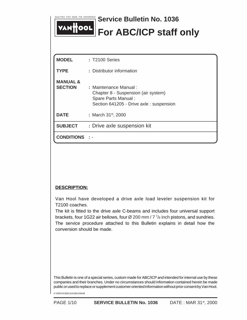
DESCRIPTION:
Van Hool have developed a drive axle load leveler suspension kit forT2100 coaches.The kit is fitted to the drive axle C-beams and includes four universal supportbrackets, four 1G22 air bellows, four Ø 200 mm / 7 7/8 inch pistons, and sundries.The service procedure attached to this Bulletin explains in detail how theconversion should be made.
Service Bulletin No. 1036
For ABC/ICP staff only
MODEL : T2100 Series
TYPE : Distributor information
MANUAL &SECTION : Maintenance Manual :
Chapter 8 - Suspension (air system)Spare Parts Manual :Section 641205 - Drive axle : suspension
DATE : March 31st, 2000
SUBJECT : Drive axle suspension kit
CONDITIONS : -
This Bulletin is one of a special series, custom made for ABC/ICP and intended for internal use by thesecompanies and their branches. Under no circumstances should information contained herein be madepublic or used to replace or supplement customer oriented information without prior consent by Van Hool.
PAGE 2/10DATE : MAR 31st, 2000
K:\SERVICEB\USA\SB1036HB
SERVICE BULLETIN No. 1036
THIS PAGE HAS BEEN LEFT BLANK INTENTIONALLY
PAGE 3/10 DATE : MAR 31st, 2000SERVICE BULLETIN No. 1036
K:\SERVICEB\USA\SB1036HB
F04791
QUALITIES THAT MAKE THE DIFFERENCE
TO FIT T2100 DRIVE AXLE LOAD LEVELERSUSPENSION KIT
1. Parts required :
Universal support bracket
1G22 air bellows, tapered
Ø 200 mm / 7 7/8 inch piston*
Bushing*
Rubber spring*
Bolt (M8x1.25x35-8.8)*
Flush head Allen bolt
(M12x1.75x35-8.8)
Self-locking nut (M12x1.75-8)
(*) The part numbers marked with an asterisk have been pre-assembled. Thesepart numbers are for reference only.
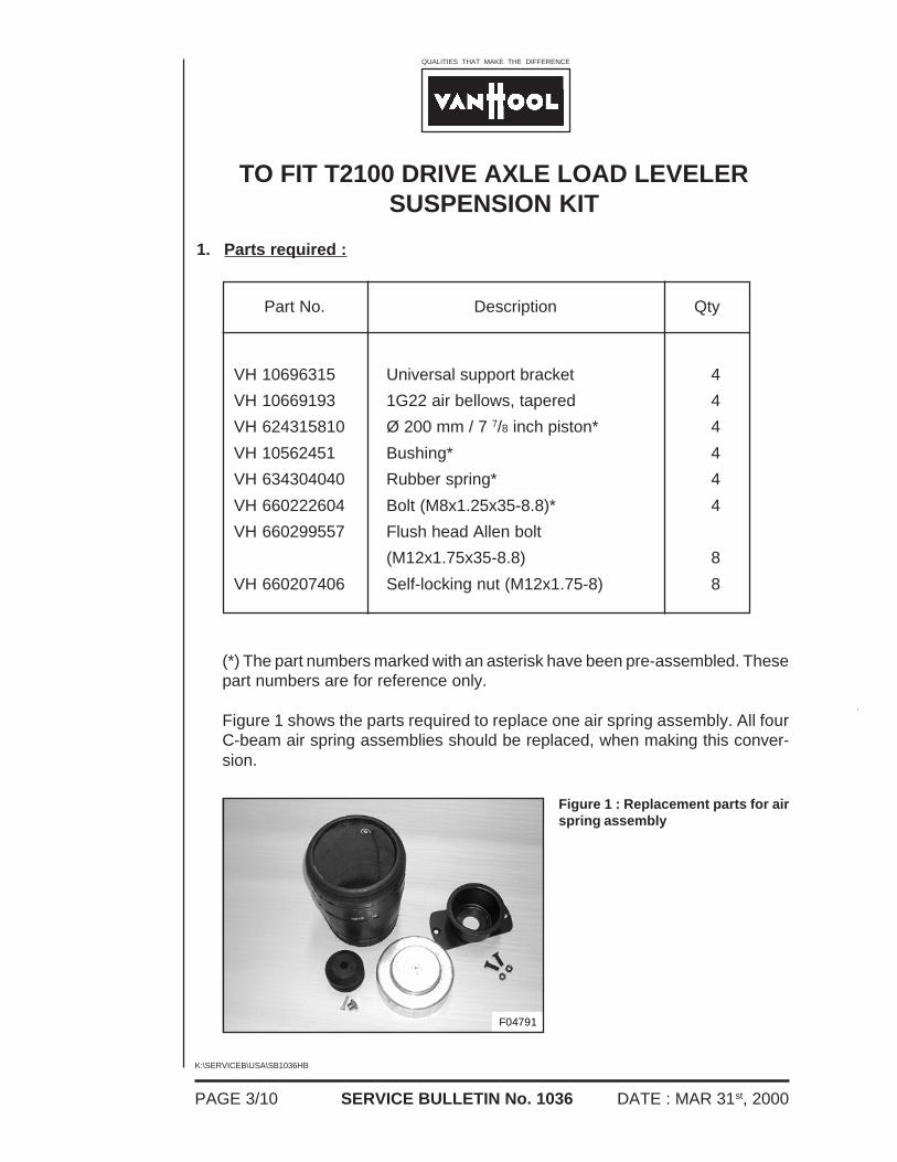
Figure 1 shows the parts required to replace one air spring assembly. All fourC-beam air spring assemblies should be replaced, when making this conver-sion.
Part No. Description Qty
VH 10696315
VH 10669193
VH 624315810
VH 10562451
VH 634304040
VH 660222604
VH 660299557
VH 660207406
4
4
4
4
4
4
8
8
Figure 1 : Replacement parts for airspring assembly
PAGE 4/10DATE : MAR 31st, 2000
K:\SERVICEB\USA\SB1036HB
SERVICE BULLETIN No. 1036
2. Tools required :
- metric socket and ratchet set- metric Allen keys- pry bar or rim tool- rubber lubricant.
3. Technician's profile :
The technician carrying out the conversion should have a thorough knowledgeof the T2100 suspension system.
4. Cautions and basic safety rules :
To avoid personal injury, when working on or around air systems and compo-nents, the following precautions should be taken :
1. Always block the vehicle wheels and shut down the engine. Venting thecoach air system may cause the vehicle to roll. Keep hands away fromchamber push rods and slack adjusters ; they may apply, as the systempressure drops. Stay away from deflating air bellows.
2. Vent all air pressure from the coach system.
3. Never connect or disconnect a hose, tube or line containing air pressure.It may whip, as air escapes. Never remove a component or open a line,unless you are certain all system air pressure has been vented.
4. Never exceed the recommended air pressure and always wear safetyglasses, when working on air systems.
5. Service procedure :
!!!CAUTION!!!
OBSERVE SAFE SHOP PRACTICES AT ALL TIMES.
READ THE ENTIRE PROCEDURE BEFORE STARTING TO WORK.
PAGE 5/10 DATE : MAR 31st, 2000SERVICE BULLETIN No. 1036
K:\SERVICEB\USA\SB1036HB
a. Preparations :
1. Park the coach on a level surfaced service pit with the front wheels straight.Shut down the engine. Make sure the vehicle is empty.
2. Lower the suspension front and rear, using the raise/lower switch on theinstrument panel. For more details refer to the Operator's Guide Booksection 2B.
3. Turn off the ignition and the master switch.
4. Chock the front road wheels.
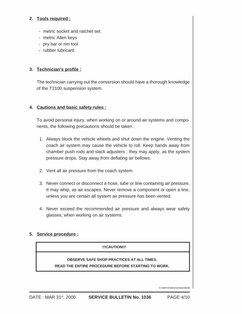
5. Working underneath the coach, vent all remaining pressure from the rearsuspension bellows by removing the rubber couplings of the tag axleleveling valves from their anchor brackets and pulling the retaining rodsdown (see Figure 2). Do not reconnect the rubber couplings until later in theprocedure.
6. Repeat step 6 at the front axle (one leveling valve only).
Figure 2 : Leveling valve link connec-tion
1. Control lever2. Retaining rod3. Rubber coupling4. Anchor bracket
T05239
PAGE 6/10DATE : MAR 31st, 2000
K:\SERVICEB\USA\SB1036HB
SERVICE BULLETIN No. 1036
F03643
F04798
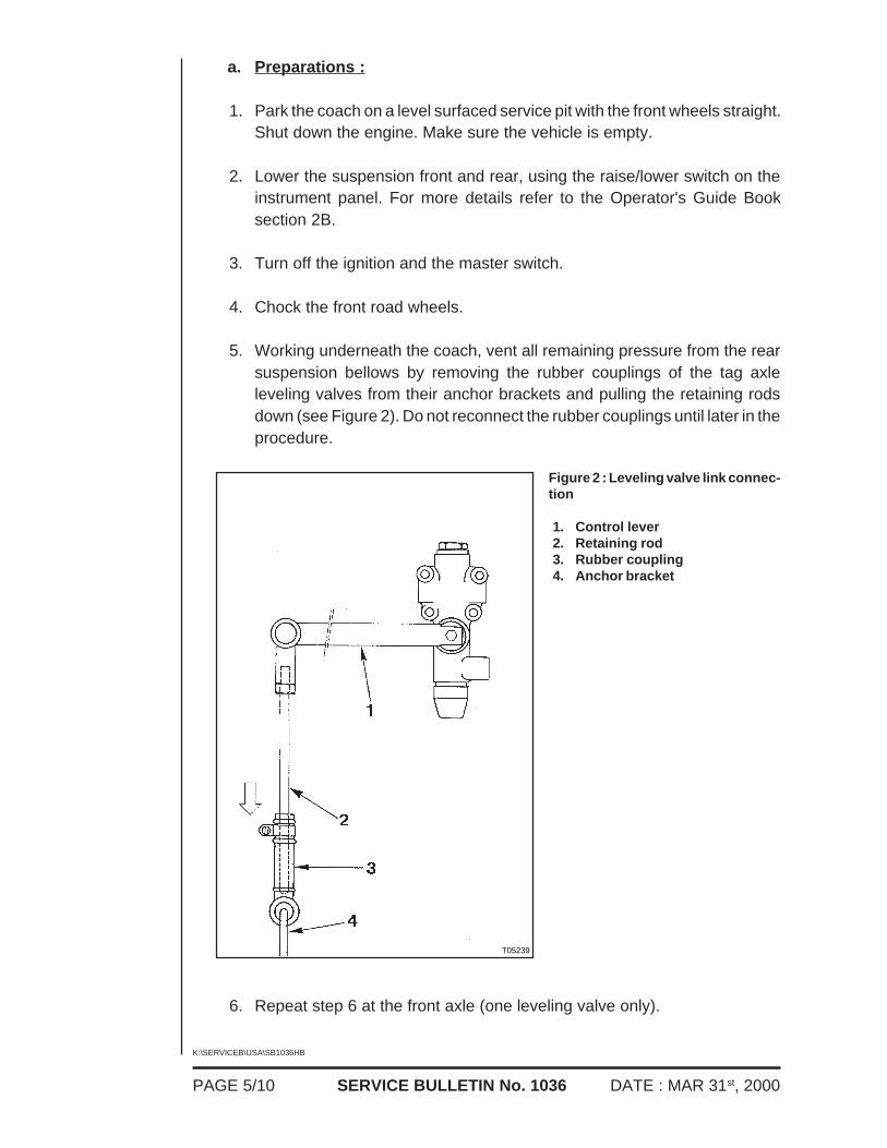
7. Jack up the rear of the coach at the drive axle differential housing (seeFigure 3), until the drive wheels are off the ground.
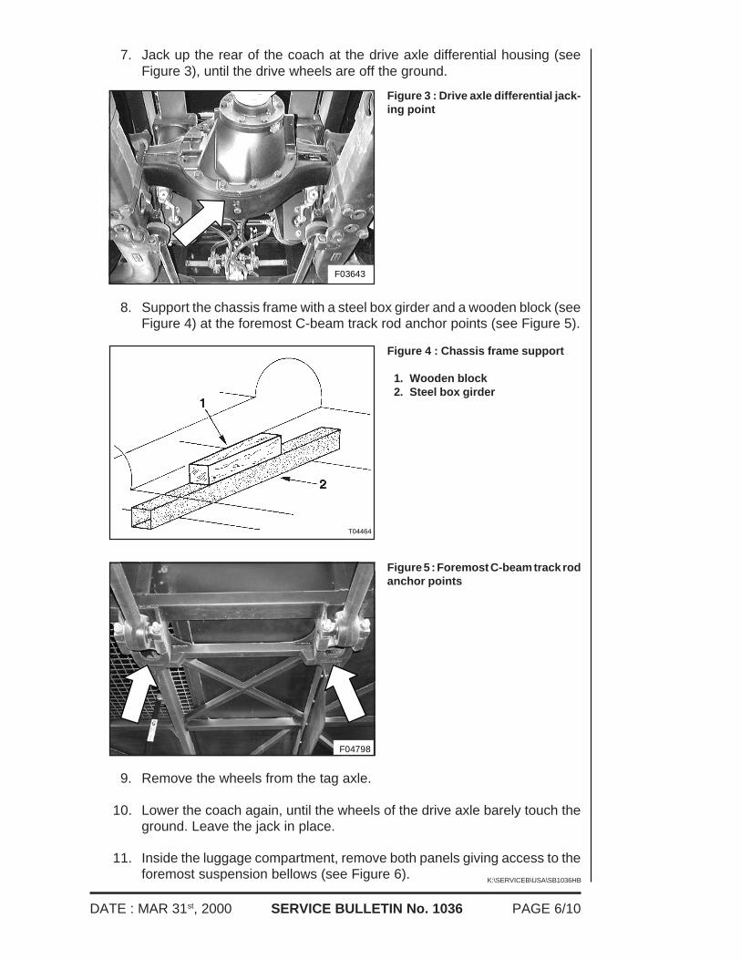
8. Support the chassis frame with a steel box girder and a wooden block (seeFigure 4) at the foremost C-beam track rod anchor points (see Figure 5).
Figure 3 : Drive axle differential jack-ing point
9. Remove the wheels from the tag axle.
10. Lower the coach again, until the wheels of the drive axle barely touch theground. Leave the jack in place.
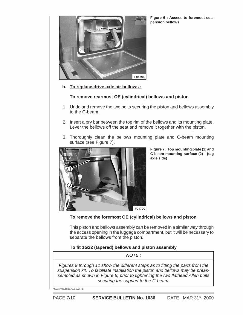
11. Inside the luggage compartment, remove both panels giving access to theforemost suspension bellows (see Figure 6).
Figure 4 : Chassis frame support
1. Wooden block2. Steel box girder
T04464
Figure 5 : Foremost C-beam track rodanchor points
PAGE 7/10 DATE : MAR 31st, 2000SERVICE BULLETIN No. 1036
K:\SERVICEB\USA\SB1036HB
F04790
F04795
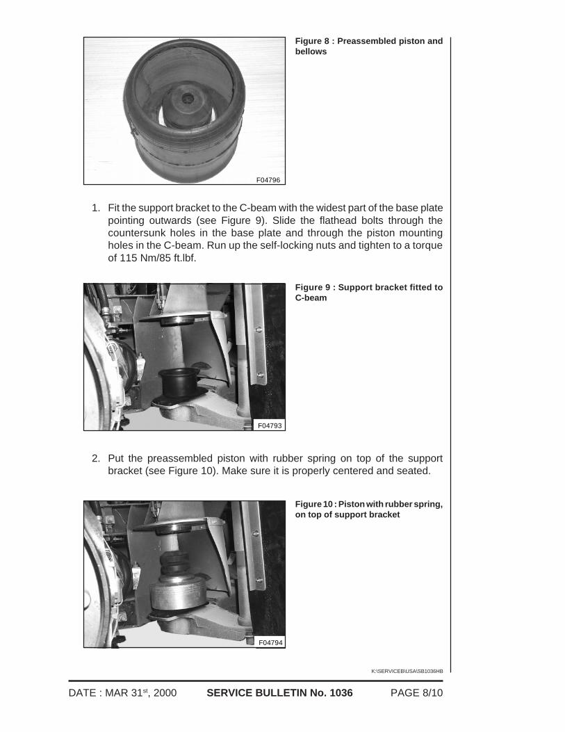
b. To replace drive axle air bellows :
To remove rearmost OE (cylindrical) bellows and piston
1. Undo and remove the two bolts securing the piston and bellows assemblyto the C-beam.
2. Insert a pry bar between the top rim of the bellows and its mounting plate.Lever the bellows off the seat and remove it together with the piston.
3. Thoroughly clean the bellows mounting plate and C-beam mountingsurface (see Figure 7).
Figure 6 : Access to foremost sus-pension bellows
To remove the foremost OE (cylindrical) bellows and piston
This piston and bellows assembly can be removed in a similar way throughthe access opening in the luggage compartment, but it will be necessary toseparate the bellows from the piston.
To fit 1G22 (tapered) bellows and piston assembly
Figure 7 : Top mounting plate (1) andC-beam mounting surface (2) - (tagaxle side)
NOTE :
Figures 9 through 11 show the different steps as to fitting the parts from thesuspension kit. To facilitate installation the piston and bellows may be preas-sembled as shown in Figure 8, prior to tightening the two flathead Allen bolts
securing the support to the C-beam.
PAGE 8/10DATE : MAR 31st, 2000
K:\SERVICEB\USA\SB1036HB
SERVICE BULLETIN No. 1036
F04794
F04793
F04796
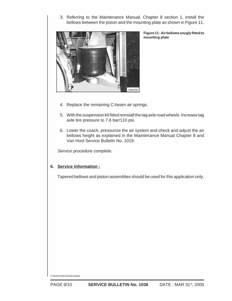
1. Fit the support bracket to the C-beam with the widest part of the base platepointing outwards (see Figure 9). Slide the flathead bolts through thecountersunk holes in the base plate and through the piston mountingholes in the C-beam. Run up the self-locking nuts and tighten to a torqueof 115 Nm/85 ft.lbf.
Figure 8 : Preassembled piston andbellows
2. Put the preassembled piston with rubber spring on top of the supportbracket (see Figure 10). Make sure it is properly centered and seated.
Figure 9 : Support bracket fitted toC-beam
Figure 10 : Piston with rubber spring,on top of support bracket
PAGE 9/10 DATE : MAR 31st, 2000SERVICE BULLETIN No. 1036
K:\SERVICEB\USA\SB1036HB
F04797
3. Referring to the Maintenance Manual, Chapter 8 section 1, install thebellows between the piston and the mounting plate as shown in Figure 11.
4. Replace the remaining C-beam air springs.
5. With the suspension kit fitted reinstall the tag axle road wheels. Increase tagaxle tire pressure to 7,6 bar/110 psi.
6. Lower the coach, pressurize the air system and check and adjust the airbellows height as explained in the Maintenance Manual Chapter 8 andVan Hool Service Bulletin No. 1019.
Service procedure complete.
6. Service information :
Tapered bellows and piston assemblies should be used for this application only.
Figure 11 : Air bellows snugly fitted tomounting plate

PAGE 10/10DATE : MAR 31st, 2000
K:\SERVICEB\USA\SB1036HB
SERVICE BULLETIN No. 1036
THIS PAGE HAS BEEN LEFT BLANK INTENTIONALLY

![a c:] 5 ooÐ L B 10.5 1 - Microsoft Word Abc Abc Abc Abc Abc Abc Abc Abc Abc Abc Abc Abc 1 - Microsoft Word Abc Abc Abc 505 7ï—L Mic SmartArt 1 - Microsoft Word Aa MS B 10.5 (Ctrl+L)](https://img.pdfslide.us/doc/110x75/5b180d777f8b9a19258b6a1e/a-c-5-ood-l-b-105-1-microsoft-word-abc-abc-abc-abc-abc-abc-abc-abc-abc-abc.jpg)