Embed Size (px)
Citation preview
BRITISH STANDARD BS EN 287-1:2011
Qualification test
of welders —
Fusion welding —
Part 1: Steels
The European Standard EN 287-1:2011 has the status of a British Standard
ICS 25.160.01
NO COPYING WITHOUT BSI PERMISSION EXCEPT AS PERMITTED BY COPYRIGHT LAW
Amd. No. Date Comments
BS EN 287-1:2011
National foreword This British Standard is the official English language version of EN 287-1:2011. It supersedes BS EN 287-1:2004 which is withdrawn. This standard was originally developed as prEN ISO 9606-1, but the ISO work item was withdrawn after the enquiry stage and the document proceeded to formal vote as a purely European work item.
The UK participation in its preparation was entrusted to Technical Committee WEE/36, Qualification of welding procedures and welders, which has the responsibility to:
— aid enquirers to understand the text;
— present to the responsible international/European committee any enquiries on the interpretation, or proposals for change, and keep the UK interests informed;
— monitor related international and European developments and promulgate them in the UK.
A list of organizations represented on this committee can be obtained on request to its secretary.
Cross-references
The British Standards which implement international or European publications referred to in this document may be found in the BSI Catalogue under the section entitled “International Standards Correspondence Index”, or by using the “Search” facility of the BSI Electronic Catalogue or of British Standards Online.
This publication does not purport to include all the necessary provisions of a contract. Users are responsible for its correct application.
Compliance with a British Standard does not of itself confer immunity from legal obligations.
This British Standard was published under the authority of the Standards Policy and Strategy Committee on 31 July 2011
© BSI 31 July 2011
ISBN 978 0 580 73042 9
Summary of pages
This document comprises a front cover, an inside front cover, the EN title page, pages 2 to 40, an inside back cover and a back cover.
The BSI copyright notice displayed in this document indicates when the document was last issued.
Amendments issued since publication
EUROPEAN STANDARD
NORME EUROPÉENNE
EUROPÄISCHE NORM
EN 287-1
July 2011
ICS 25.160.01 Supersedes EN 287-1:2004
English Version
Qualification test of welders - Fusion welding - Part 1: Steels
Epreuve de qualification des soudeurs - Soudage par fusion - Partie 1 : Aciers
Prüfung von Schweißern - Schmelzschweißen - Teil 1: Stähle
This European Standard was approved by CEN on 16 June 2011. CEN members are bound to comply with the CEN/CENELEC Internal Regulations which stipulate the conditions for giving this European Standard the status of a national standard without any alteration. Up-to-date lists and bibliographical references concerning such national standards may be obtained on application to the CEN-CENELEC Management Centre or to any CEN member. This European Standard exists in three official versions (English, French, German). A version in any other language made by translation under the responsibility of a CEN member into its own language and notified to the CEN-CENELEC Management Centre has the same status as the official versions. CEN members are the national standards bodies of Austria, Belgium, Bulgaria, Croatia, Cyprus, Czech Republic, Denmark, Estonia, Finland, France, Germany, Greece, Hungary, Iceland, Ireland, Italy, Latvia, Lithuania, Luxembourg, Malta, Netherlands, Norway, Poland, Portugal, Romania, Slovakia, Slovenia, Spain, Sweden, Switzerland and United Kingdom.
EUROPEAN COMMITTEE FOR STANDARDIZATION C O M I T É E U R O P É E N D E N O R M A LI S A T I O N EUR OP ÄIS C HES KOM ITEE FÜR NOR M UNG
Management Centre: Avenue Marnix 17, B-1000 Brussels
© 2011 CEN All rights of exploitation in any form and by any means reserved worldwide for CEN national Members.
Ref. No. EN 287-1:2011: E
EN 287-1:2011 (E)
2
Contents Page
Foreword ..............................................................................................................................................................4
Introduction .........................................................................................................................................................5
1 Scope ......................................................................................................................................................6
2 Normative references ............................................................................................................................6
3 Terms and definitions ...........................................................................................................................6
4 Reference numbers, symbols and abbreviated terms .......................................................................84.1 General ....................................................................................................................................................84.2 Reference numbers of welding processes .........................................................................................84.3 Symbols and abbreviations ..................................................................................................................94.3.1 For test pieces ........................................................................................................................................94.3.2 For consumables ...................................................................................................................................94.3.3 For other weld details ......................................................................................................................... 104.3.4 For bend tests ..................................................................................................................................... 10
5 Essential variables and range of qualification ................................................................................ 115.1 General ................................................................................................................................................. 115.2 Welding processes ............................................................................................................................. 115.3 Product type ........................................................................................................................................ 125.4 Type of weld ........................................................................................................................................ 125.5 Material groups ................................................................................................................................... 135.5.1 Steel groups of parent material ......................................................................................................... 135.5.2 Range of qualification ........................................................................................................................ 135.6 Filler materials ..................................................................................................................................... 145.7 Dimensions .......................................................................................................................................... 155.8 Welding positions ............................................................................................................................... 165.9 Weld details ......................................................................................................................................... 17
6 Examination and testing .................................................................................................................... 186.1 Examination ......................................................................................................................................... 186.2 Test pieces .......................................................................................................................................... 186.3 Welding conditions ............................................................................................................................. 216.4 Test methods ....................................................................................................................................... 216.5 Test piece and test specimen ............................................................................................................ 226.5.1 General ................................................................................................................................................. 226.5.2 Butt weld in plate and pipe ................................................................................................................ 226.5.3 Fillet weld on plate .............................................................................................................................. 236.5.4 Fillet weld on pipe ............................................................................................................................... 266.6 Test record .......................................................................................................................................... 26
7 Acceptance requirements for test pieces ........................................................................................ 27
8 Re-tests ................................................................................................................................................ 27
9 Period of validity ................................................................................................................................. 279.1 Initial qualification .............................................................................................................................. 279.2 Confirmation of the validity ............................................................................................................... 279.3 Prolongation of qualification ............................................................................................................. 28
10 Certificate ............................................................................................................................................ 28
11 Designation ......................................................................................................................................... 28
Annex A (informative) Welder's qualification test certificate ...................................................................... 30
Annex B (informative) Designation examples ............................................................................................... 31
EN 287-1:2011 (E)
3
B.1 Example 1 ............................................................................................................................................. 31B.2 Example 2 ............................................................................................................................................. 31B.3 Example 3 ............................................................................................................................................. 32B.4 Example 4 ............................................................................................................................................. 32B.5 Example 5 ............................................................................................................................................. 33B.6 Example 6 ............................................................................................................................................. 33B.7 Example 7 ............................................................................................................................................. 34
Annex C (informative) Job knowledge ............................................................................................................ 35C.1 General ................................................................................................................................................. 35C.2 Requirements ....................................................................................................................................... 35C.2.1 Welding equipment ............................................................................................................................. 35C.2.2 Welding process ................................................................................................................................. 36C.2.3 Parent metals ....................................................................................................................................... 36C.2.4 Welding consumables ......................................................................................................................... 36C.2.5 Safety precautions .............................................................................................................................. 37C.2.6 Welding sequences/procedures ........................................................................................................ 37C.2.7 Joint preparation and weld representation....................................................................................... 37C.2.8 Weld imperfections ............................................................................................................................. 37C.2.9 Welder qualification ............................................................................................................................ 38
Annex ZA (informative) Relationship between this European Standard and the Essential Requirements of EC Directive 97/23/EC ............................................................................................ 39
Bibliography ...................................................................................................................................................... 40
EN 287-1:2011 (E)
4
Foreword
This document (EN 287-1:2011) has been prepared by Technical Committee CEN/TC 121 “Welding”, the secretariat of which is held by DIN.
This European Standard shall be given the status of a national standard, either by publication of an identical text or by endorsement, at the latest by January 2012, and conflicting national standards shall be withdrawn at the latest by January 2012.
Attention is drawn to the possibility that some of the elements of this document may be the subject of patent rights. CEN [and/or CENELEC] shall not be held responsible for identifying any or all such patent rights.
This document supersedes EN 287-1:2004.
This document has been prepared under a mandate given to CEN by the European Commission and the European Free Trade Association, and supports essential requirements of EU Directive(s).
For relationship with EU Directive(s), see informative Annex ZA, which is an integral part of this document.
According to the CEN/CENELEC Internal Regulations, the national standards organizations of the following countries are bound to implement this European Standard: Austria, Belgium, Bulgaria, Croatia, Cyprus, Czech Republic, Denmark, Estonia, Finland, France, Germany, Greece, Hungary, Iceland, Ireland, Italy, Latvia, Lithuania, Luxembourg, Malta, Netherlands, Norway, Poland, Portugal, Romania, Slovakia, Slovenia, Spain, Sweden, Switzerland and the United Kingdom.
EN 287-1:2011 (E)
5
Introduction
The ability of a welder to follow verbal or written instructions and verification of a person's skills is an important factors in ensuring the quality of the welded product.
The testing of a welder's skill in accordance with this standard depends on welding techniques and conditions used in which uniform rules are complied with and standard test pieces are used.
The principle of this standard is that a qualification test qualifies the welder not only for the conditions used in the test, but also for all joints which are considered easier to weld on the presumption that the welder has received a specific training and/or has industrial practice within the range of qualification.
The qualification test can be used to qualify a welding procedure and a welder provided that all the relevant requirements, e.g. test piece dimensions and testing requirements are satisfied (see EN ISO 15614-1).
At the end of its period of validity, the existing and valid qualification testing of welders in accordance with the requirement of the previous edition of this standard may be revalidated according to the previous edition. Alternatively, the range of qualification may be updated in accordance with this edition. All new qualifications and re-qualifications shall be in accordance with this edition.
EN 287-1:2011 (E)
6
1 Scope
This European Standard defines the qualification testing of welders for the fusion welding of steels.
It provides a set of technical rules for a systematic qualification test of the welder, and enables such qualifications to be uniformly accepted independently of the type of product, location and examiner/examining body.
When qualifying welders, the emphasis is placed on the welder's ability to manually manipulate the electrode / welding torch / welding blowpipe and thereby producing a weld of acceptable quality.
The welding processes referred to in this standard include those fusion-welding processes which are designated as manual or partly mechanized welding. It does not cover fully mechanized and automated welding processes (see EN 1418).
2 Normative references
The following referenced documents are indispensable for the application of this document. For dated references, only the edition cited applies. For undated references, the latest edition of the referenced document (including any amendments) applies.
EN 1320:1996, Destructive tests on welds in metallic materials — Fracture test
EN 1435:1997, Non-destructive examination of welds — Radiographic examination of welded joints
EN ISO 4063:2009, Welding and allied processes — Nomenclature of processes and reference numbers (ISO 4063:2009)
EN ISO 5173:2010, Destructive tests on welds in metallic materials — Bend tests (ISO 5173:2009)
EN ISO 5817:2007, Welding — Fusion-welded joints in steel, nickel, titanium and their alloys (beam welding excluded) — Quality levels for imperfections (ISO 5817:2003, corrected version:2005, including Technical Corrigendum 1:2006)
EN ISO 6947, Welding and allied processes – Welding positions (ISO 6947:2011)
CEN ISO/TR 15608, Welding — Guidelines for a metallic materials grouping system (ISO/TR 15608:2005)
EN ISO 15609-1:2004, Specification and qualification of welding procedures for metallic materials — Welding procedure specification — Part 1: Arc welding (ISO 15609-1:2004)
EN ISO 15609-2:2001, Specification and qualification of welding procedures for metallic materials — Welding procedure specification — Part 2: Gas welding (ISO 15609-2:2001)
EN ISO 17637, Non-destructive testing of welds - Visual testing of fusion-welded joints (ISO 17637:2003)
ISO 857-1:1998, Welding and allied processes — Vocabulary — Part 1: Metal welding processes
3 Terms and definitions
For the purposes of this document, the following terms and definitions apply.
3.1 welder person who holds and manipulates the electrode holder, welding torch or blowpipe by hand
EN 287-1:2011 (E)
7
[ISO/TR 25901:2007]
3.2 manufacturer person or organization that is responsible for the welding production
[EN ISO 15607:2003]
3.3 examiner qualified person who has been appointed to verify compliance with the applicable standard
NOTE In certain cases, an external independent examiner can be required.
3.4 examining body organization that has been appointed to verify compliance with the applicable standard
NOTE In certain cases, an external independent examining body can be required.
[ISO/TR 25901:2007]
3.5 material backing backing using material for the purpose of supporting molten weld metal
3.6 layer stratum of weld metal consisting of one or more runs
[ISO/TR 25901:2007]
3.7 root run in multi layer welding, the run(s) of the first layer deposited in the root
[ISO/TR 25901:2007]
3.8 filling run in multi layer welding, the run(s) deposited after the root run(s) and before the capping run(s)
[ISO/TR 25901:2007]
3.9 capping run in multi layer welding, the run(s) visible on the weld face(s) after completion of welding
[ISO/TR 25901:2007]
3.10 deposited thickness thickness of the weld metal excluding any reinforcement
[ISO/TR 25901:2007]
3.11 leftward welding gas welding technique in which the filler rod is moved ahead of the blow pipe in relation to the welding direction
EN 287-1:2011 (E)
8
[ISO/TR 25901:2007]
3.12 rightward welding gas welding technique in which the filler rod is moved behind the blow pipe in relation to the welding direction
[ISO/TR 25901:2007]
3.13 branch connection joint of one or two tubular parts at an angle of less than 180°
3.14 fillet weld triangular weld in a square preparation for making a T-joint, corner joint or lap joint
[ISO/TR 25901:2007]
3.15 verification confirmation, through the provision of objective evidence, that specified requirements have been fulfilled
[ISO 9000:2005]
3.16 filler material welding consumable added during welding to form the weld
[ISO/TR 25901:2007]
3.17 butt weld weld other than a fillet weld (3.14) made in a groove or in a square preparation
[ISO/TR 25901:2007]
4 Reference numbers, symbols and abbreviated terms
4.1 General
The following abbreviations and reference numbers shall be used when completing the welder's qualification test certificate (see Annex A).
4.2 Reference numbers of welding processes
This standard covers the following manual or partly mechanized welding processes (reference numbers of welding processes for symbolic representation are listed in EN ISO 4063:2009):
111 manual metal arc welding;
114 self-shielded tubular-cored arc welding;
121 submerged arc welding with solid wire electrode (partly mechanized);
125 submerged arc welding with tubular cored electrode (partly mechanized);
131 MIG welding with solid wire electrode;
EN 287-1:2011 (E)
9
135 MAG welding with solid wire electrode;
136 MAG welding with flux cored electrode;
138 MAG welding with metal cored electrode;
141 TIG welding with solid filler material;
142 Autogenous TIG welding;
143 TIG welding with tubular cored filler material;
145 TIG welding using reducing gas and solid filler material;
15 plasma arc welding;
311 oxy-acetylene welding.
NOTE The principles of this standard can be applied to other fusion welding processes.
4.3 Symbols and abbreviations
4.3.1 For test pieces
BW butt weld
D outside pipe diameter
FW fillet weld
l1 length of test piece
l2 half width of test piece
lf examination length
P plate
ReH yield strength
s1 deposited thickness of weld metal for welding process 1
s2 deposited thickness of weld metal for welding process 2
t material thickness of test piece (plate or wall thickness)
T pipe 1)
4.3.2 For consumables
nm no filler metal
A acid covering
1) The word "pipe" alone or in combination, is used to mean "pipe", "tube" or "hollow section".
EN 287-1:2011 (E)
10
B basic covering or electrode core - basic
C cellulosic covering
M electrode core - metal powder
P electrode core - rutile, fast freezing slag
R rutile covering or electrode core – rutile, slow freezing slag
RA rutile-acid covering
RB rutile-basic covering
RC rutile-cellulosic covering
RR rutile-thick covering
S solid wire/rod
V electrode core - rutile or basic / fluoride
W electrode core - basic / fluoride, slow freezing slag
Y electrode core - basic / fluoride, fast freezing slag
Z electrode core - other types
4.3.3 For other weld details
bs welding from both sides
lw leftward welding
mb welding with backing
ml multi layer
nb welding without backing
rw rightward welding
sl single layer
ss single-side welding
4.3.4 For bend tests
A minimum tensile elongation required by the material specification
d diameter of the former or the inner roller
ts thickness of the bend test specimen
EN 287-1:2011 (E)
11
5 Essential variables and range of qualification
5.1 General
The qualification of welders is based on essential variables. For each essential variable a range of qualification is defined. All test pieces shall be welded using the essential variables independently, except for 5.7 and 5.8. If the welder has to weld outside the range of qualification a new qualification test is required. The essential variables are:
welding process(es);
product type (plate and pipe);
type of weld (butt and fillet);
material group;
filler material;
dimension (material thickness and outside pipe diameter);
welding position;
weld detail (backing, single side welding, both side welding, single layer, multi layer, leftward welding, rightward welding).
5.2 Welding processes
Welding processes are defined in ISO 857-1 and listed in 4.2.
Each qualification test normally qualifies only one welding process. A change of welding process requires a new qualification test. Exceptions are as follows:
a change from solid wire electrode 135 to a metal cored electrode 138 or vice versa does not require requalification. (see Table 4);
welding with 141, 143 or 145 qualifies for 141, 142, 143 and 145 but 142 only qualifies for 142.
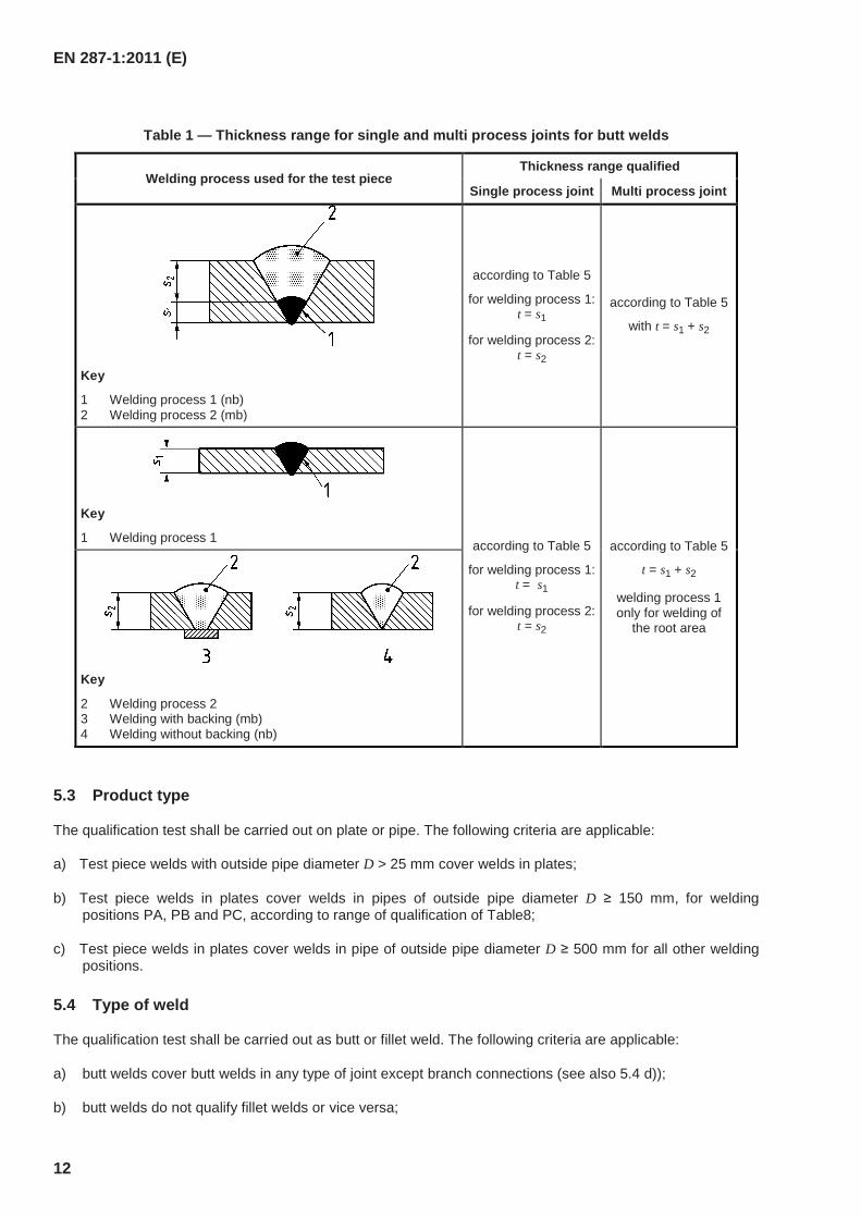
However, it is permitted for a welder to be qualified for two or more welding processes by welding a single test piece (multi process joint) or by two or more separate qualification tests. The ranges of qualification concerning the deposited thickness of weld metal for each welding process used and for the multi process joint for butt welds are given in Table 1 (see also Table 5).
EN 287-1:2011 (E)
12
Table 1 — Thickness range for single and multi process joints for butt welds
Welding process used for the test piece Thickness range qualified
Single process joint Multi process joint
Key
1 Welding process 1 (nb) 2 Welding process 2 (mb)
according to Table 5
for welding process 1: t = s1
for welding process 2: t = s2
according to Table 5
with t = s1 + s2
Key
1 Welding process 1 according to Table 5
for welding process 1: t = s1
for welding process 2: t = s2
according to Table 5
t = s1 + s2
welding process 1 only for welding of
the root area
Key
2 Welding process 2 3 Welding with backing (mb) 4 Welding without backing (nb)
5.3 Product type
The qualification test shall be carried out on plate or pipe. The following criteria are applicable:
a) Test piece welds with outside pipe diameter D > 25 mm cover welds in plates;
b) Test piece welds in plates cover welds in pipes of outside pipe diameter D ≥ 150 mm, for welding positions PA, PB and PC, according to range of qualification of Table8;
c) Test piece welds in plates cover welds in pipe of outside pipe diameter D ≥ 500 mm for all other welding positions.
5.4 Type of weld
The qualification test shall be carried out as butt or fillet weld. The following criteria are applicable:
a) butt welds cover butt welds in any type of joint except branch connections (see also 5.4 d));
b) butt welds do not qualify fillet welds or vice versa;
EN 287-1:2011 (E)
13
c) when a welder is qualified by butt weld test, a supplementary fillet weld test piece can be welded which shall be in a plate thickness of at least 10 mm and completed using a single layer in the PB position. For this supplementary test the welder shall become qualified for all fillet welds as given for the butt weld qualifications;
d) butt welds in pipes qualify branch connections with an angle ≥ 60° and the same range of qualification as in Tables 1 to 8. For a branch weld the range of qualification is based on the outside pipe diameter of the branch;
e) for applications where the type of weld cannot be qualified by means of either a butt or fillet weld test then a specific test piece should be used to qualify the welder, e.g. branch connection.
5.5 Material groups
5.5.1 Steel groups of parent material
In order to reduce the number of qualification tests, materials with similar welding characteristics are grouped according to CEN ISO/TR 15608.
NOTE Examples of parent material in accordance with the grouping system in CEN ISO/TR 15608 are given in CEN ISO/TR 20172, CEN ISO/TR 20173 and CEN ISO/TR 20174.
5.5.2 Range of qualification
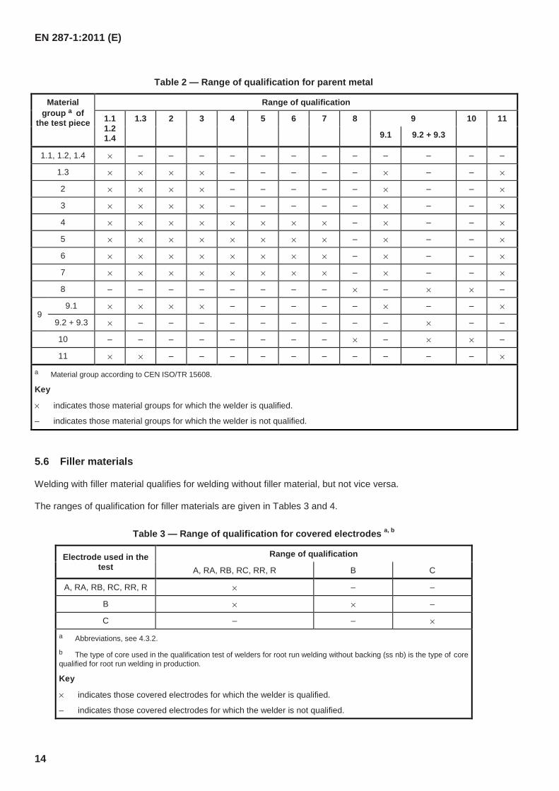
The welding of any one metal in a material group covers qualification on the welder for the welding of all other metal within the same material group as well as other material groups according to Table 2.
When welding parent materials outside the grouping system, a separate qualification test is required.
Qualification of dissimilar metal joints: When using filler metals from the material group 8 or 10 (see Table 2), all combinations with the material group 8 or 10 to other material groups are covered.
A qualification test made on wrought material groups gives qualification for cast material and a mixture of cast and wrought material in the same material group.
EN 287-1:2011 (E)
14
Table 2 — Range of qualification for parent metal
Material group a of
the test piece
Range of qualification
1.1 1.2 1.4
1.3 2 3 4 5 6 7 8 9 10 11
9.1 9.2 + 9.3
1.1, 1.2, 1.4 × – – – – – – – – – – – –
1.3 × × × × – – – – – × – – ×
2 × × × × – – – – – × – – ×
3 × × × × – – – – – × – – ×
4 × × × × × × × × – × – – ×
5 × × × × × × × × – × – – ×
6 × × × × × × × × – × – – ×
7 × × × × × × × × – × – – ×
8 – – – – – – – – × – × × –
9 9.1 × × × × – – – – – × – – ×
9.2 + 9.3 × – – – – – – – – – × – –
10 – – – – – – – – × – × × –
11 × × – – – – – – – – – – ×
a Material group according to CEN ISO/TR 15608.
Key
× indicates those material groups for which the welder is qualified.
– indicates those material groups for which the welder is not qualified.
5.6 Filler materials
Welding with filler material qualifies for welding without filler material, but not vice versa.
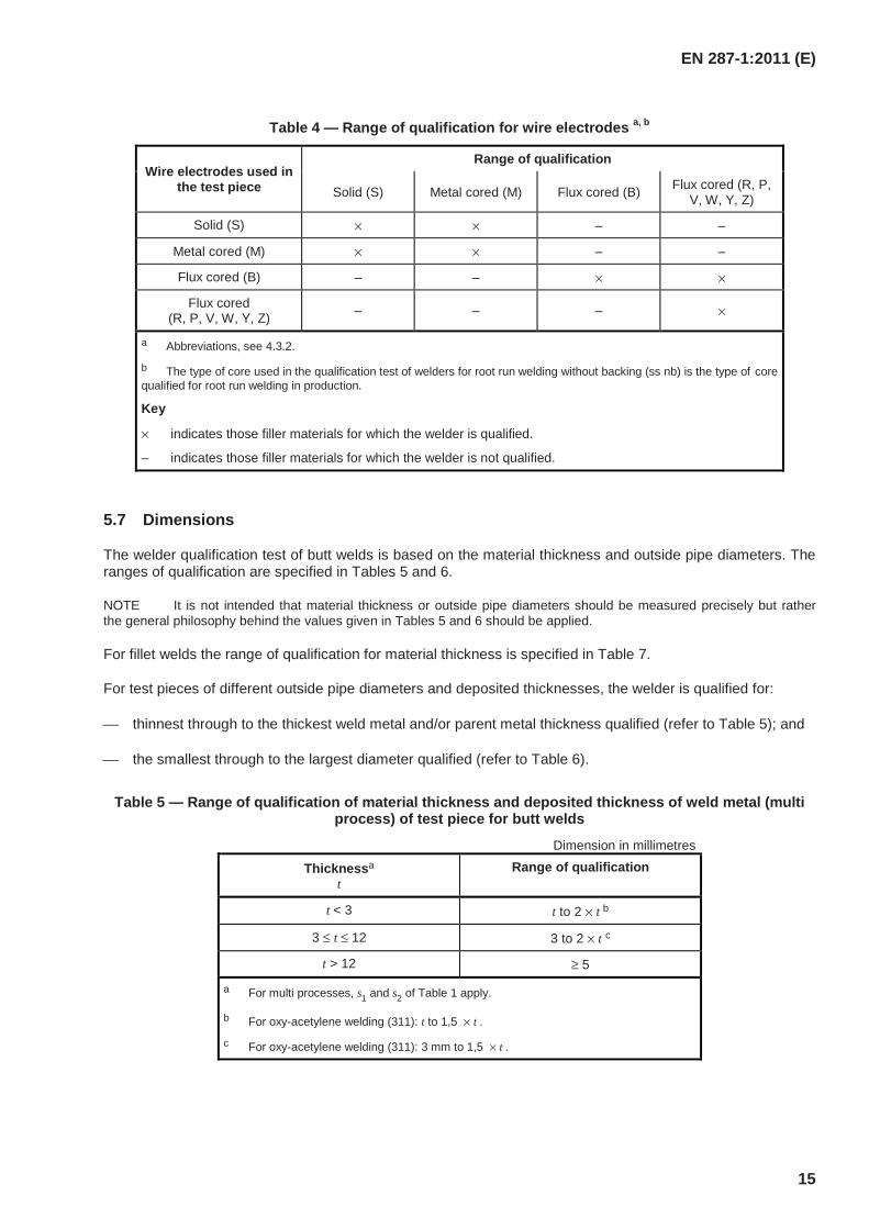
The ranges of qualification for filler materials are given in Tables 3 and 4.
Table 3 — Range of qualification for covered electrodes a, b
Electrode used in the test
Range of qualification
A, RA, RB, RC, RR, R B C
A, RA, RB, RC, RR, R × – –
B × × –
C – – ×
a Abbreviations, see 4.3.2.
b The type of core used in the qualification test of welders for root run welding without backing (ss nb) is the type of core qualified for root run welding in production.
Key
× indicates those covered electrodes for which the welder is qualified.
– indicates those covered electrodes for which the welder is not qualified.
EN 287-1:2011 (E)
15
Table 4 — Range of qualification for wire electrodes a, b
Wire electrodes used in the test piece
Range of qualification
Solid (S) Metal cored (M) Flux cored (B) Flux cored (R, P, V, W, Y, Z)
Solid (S) × × – –
Metal cored (M) × × – –
Flux cored (B) – – × ×
Flux cored (R, P, V, W, Y, Z) – – – ×
a Abbreviations, see 4.3.2.
b The type of core used in the qualification test of welders for root run welding without backing (ss nb) is the type of core qualified for root run welding in production.
Key
× indicates those filler materials for which the welder is qualified.
– indicates those filler materials for which the welder is not qualified.
5.7 Dimensions
The welder qualification test of butt welds is based on the material thickness and outside pipe diameters. The ranges of qualification are specified in Tables 5 and 6.
NOTE It is not intended that material thickness or outside pipe diameters should be measured precisely but rather the general philosophy behind the values given in Tables 5 and 6 should be applied.
For fillet welds the range of qualification for material thickness is specified in Table 7.
For test pieces of different outside pipe diameters and deposited thicknesses, the welder is qualified for:
thinnest through to the thickest weld metal and/or parent metal thickness qualified (refer to Table 5); and
the smallest through to the largest diameter qualified (refer to Table 6).
Table 5 — Range of qualification of material thickness and deposited thickness of weld metal (multi process) of test piece for butt welds
Dimension in millimetres
Thicknessa t
Range of qualification
t < 3 t to 2 × t b
3 ≤ t ≤ 12 3 to 2 × t c
t > 12 ≥ 5
a For multi processes, s1 and s2 of Table 1 apply.
b For oxy-acetylene welding (311): t to 1,5 × t .
c For oxy-acetylene welding (311): 3 mm to 1,5 × t .
EN 287-1:2011 (E)
16
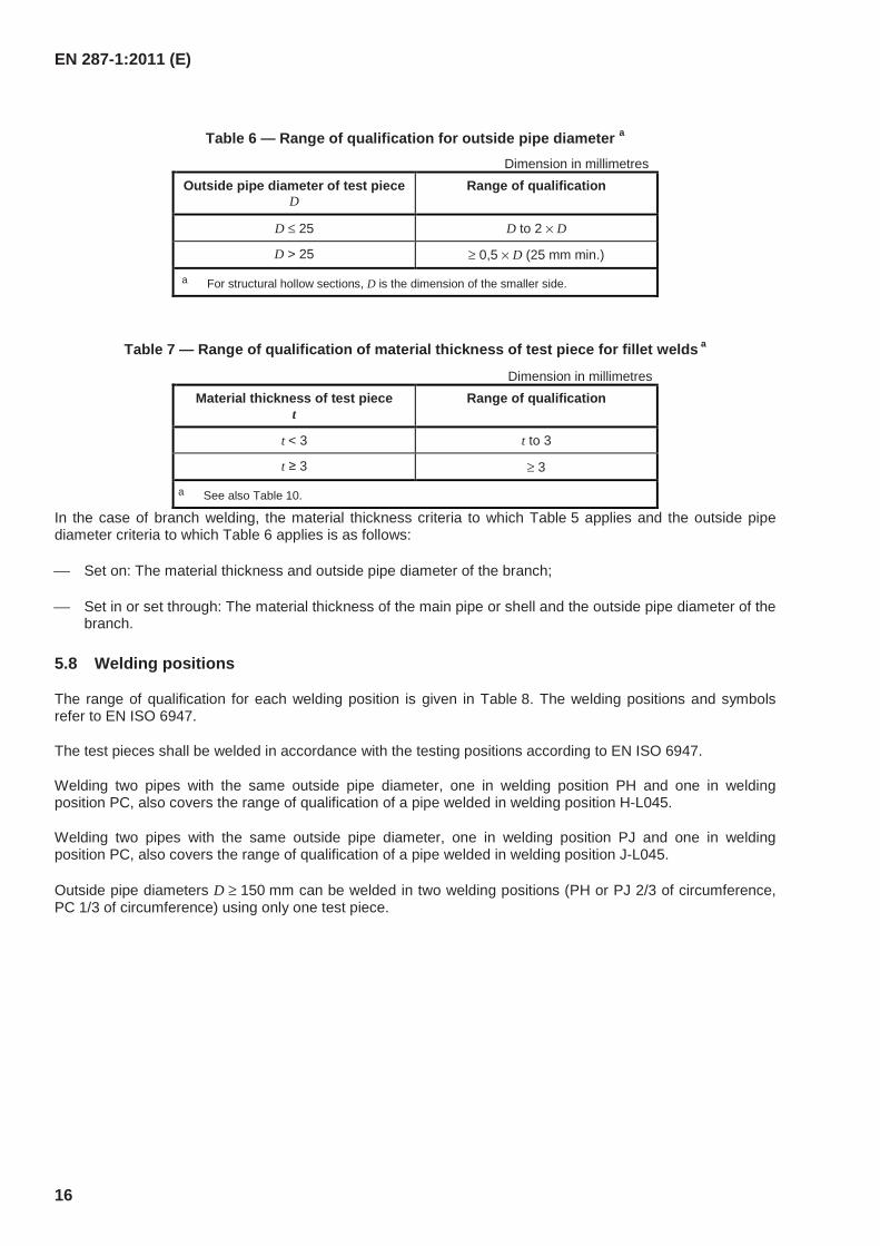
Table 6 — Range of qualification for outside pipe diameter a Dimension in millimetres
Outside pipe diameter of test pieceD
Range of qualification
D ≤ 25 D to 2 × D
D > 25 ≥ 0,5 × D (25 mm min.)
a For structural hollow sections, D is the dimension of the smaller side.
Table 7 — Range of qualification of material thickness of test piece for fillet welds a
Dimension in millimetres Material thickness of test piece
t Range of qualification
t < 3 t to 3
t ≥ 3 ≥ 3
a See also Table 10.
In the case of branch welding, the material thickness criteria to which Table 5 applies and the outside pipe diameter criteria to which Table 6 applies is as follows:
Set on: The material thickness and outside pipe diameter of the branch;
Set in or set through: The material thickness of the main pipe or shell and the outside pipe diameter of the branch.
5.8 Welding positions
The range of qualification for each welding position is given in Table 8. The welding positions and symbols refer to EN ISO 6947.
The test pieces shall be welded in accordance with the testing positions according to EN ISO 6947.
Welding two pipes with the same outside pipe diameter, one in welding position PH and one in welding position PC, also covers the range of qualification of a pipe welded in welding position H-L045.
Welding two pipes with the same outside pipe diameter, one in welding position PJ and one in welding position PC, also covers the range of qualification of a pipe welded in welding position J-L045.
Outside pipe diameters D ≥ 150 mm can be welded in two welding positions (PH or PJ 2/3 of circumference, PC 1/3 of circumference) using only one test piece.
EN 287-1:2011 (E)
17
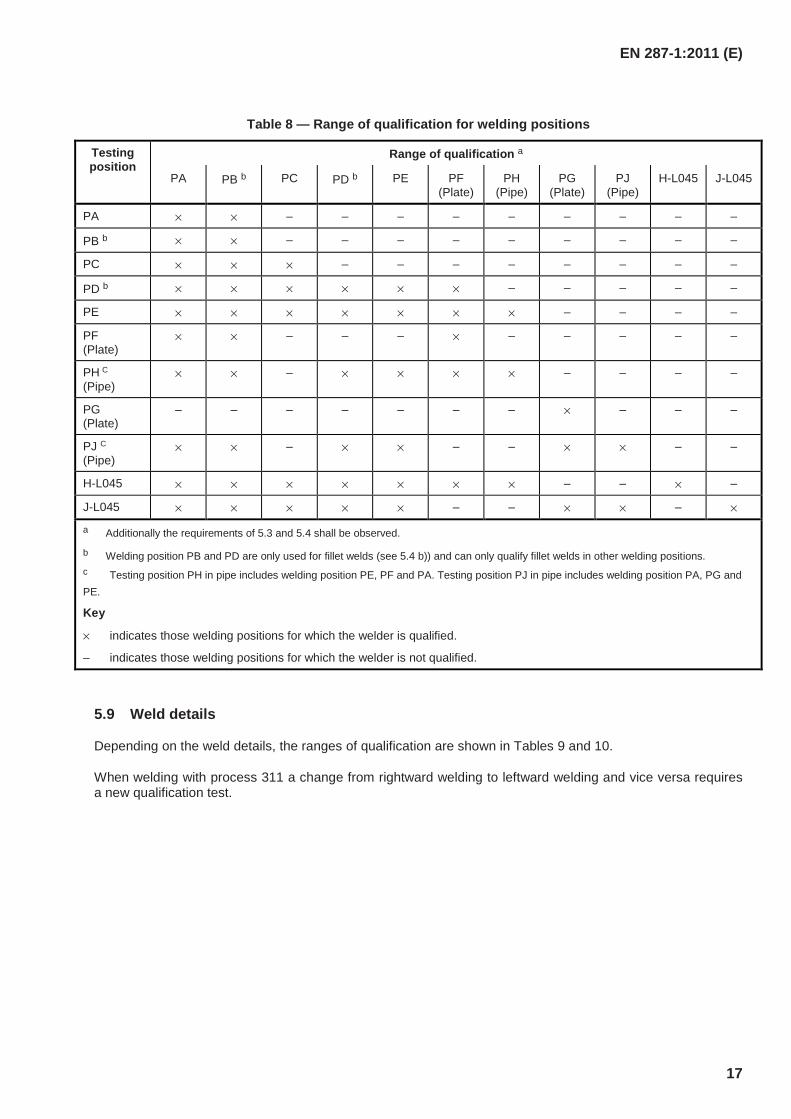
Table 8 — Range of qualification for welding positions
Testing position
Range of qualification a
PA PB b PC PD b PE PF (Plate)
PH (Pipe)
PG (Plate)
PJ (Pipe)
H-L045 J-L045
PA × × – – – – – – – – –
PB b × × – – – – – – – – –
PC × × × – – – – – – – –
PD b × × × × × × – – – – –
PE × × × × × × × – – – –
PF (Plate)
× × – – – × – – – – –
PH C
(Pipe) × × – × × × × – – – –
PG (Plate)
– – – – – – – × – – –
PJ C (Pipe)
× × – × × – – × × – –
H-L045 × × × × × × × – – × –
J-L045 × × × × × – – × × – ×
a Additionally the requirements of 5.3 and 5.4 shall be observed.
b Welding position PB and PD are only used for fillet welds (see 5.4 b)) and can only qualify fillet welds in other welding positions. c Testing position PH in pipe includes welding position PE, PF and PA. Testing position PJ in pipe includes welding position PA, PG and PE.
Key
× indicates those welding positions for which the welder is qualified.
– indicates those welding positions for which the welder is not qualified.
5.9 Weld details
Depending on the weld details, the ranges of qualification are shown in Tables 9 and 10.
When welding with process 311 a change from rightward welding to leftward welding and vice versa requires a new qualification test.
EN 287-1:2011 (E)
18
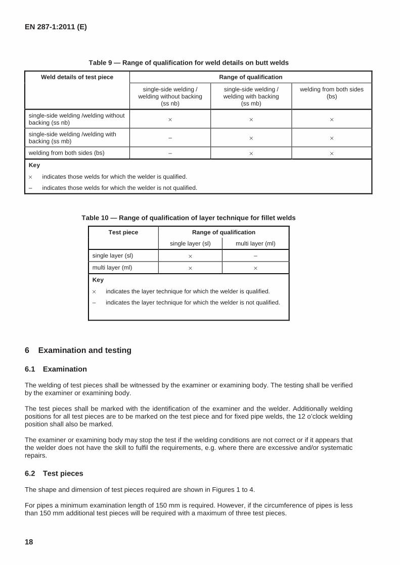
Table 9 — Range of qualification for weld details on butt welds
Weld details of test piece Range of qualification
single-side welding / welding without backing
(ss nb)
single-side welding / welding with backing
(ss mb)
welding from both sides (bs)
single-side welding /welding without backing (ss nb) × × ×
single-side welding /welding with backing (ss mb) – × ×
welding from both sides (bs) – × ×
Key
× indicates those welds for which the welder is qualified.
– indicates those welds for which the welder is not qualified.
Table 10 — Range of qualification of layer technique for fillet welds
Test piece Range of qualification
single layer (sl) multi layer (ml)
single layer (sl) × –
multi layer (ml) × ×
Key
× indicates the layer technique for which the welder is qualified.
– indicates the layer technique for which the welder is not qualified.
6 Examination and testing
6.1 Examination
The welding of test pieces shall be witnessed by the examiner or examining body. The testing shall be verified by the examiner or examining body.
The test pieces shall be marked with the identification of the examiner and the welder. Additionally welding positions for all test pieces are to be marked on the test piece and for fixed pipe welds, the 12 o’clock welding position shall also be marked.
The examiner or examining body may stop the test if the welding conditions are not correct or if it appears that the welder does not have the skill to fulfil the requirements, e.g. where there are excessive and/or systematic repairs.
6.2 Test pieces
The shape and dimension of test pieces required are shown in Figures 1 to 4.
For pipes a minimum examination length of 150 mm is required. However, if the circumference of pipes is less than 150 mm additional test pieces will be required with a maximum of three test pieces.
EN 287-1:2011 (E)
19
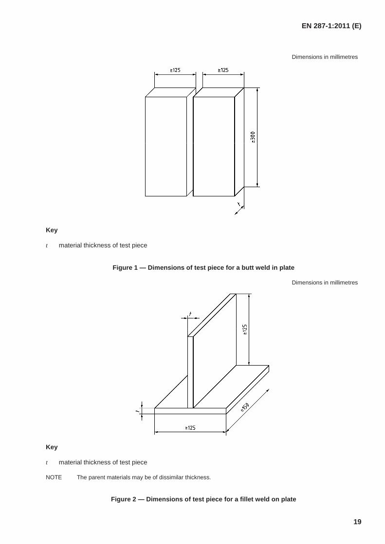
Dimensions in millimetres
Key
t material thickness of test piece
Figure 1 — Dimensions of test piece for a butt weld in plate
Dimensions in millimetres
Key
t material thickness of test piece
NOTE The parent materials may be of dissimilar thickness.
Figure 2 — Dimensions of test piece for a fillet weld on plate
EN 287-1:2011 (E)
20
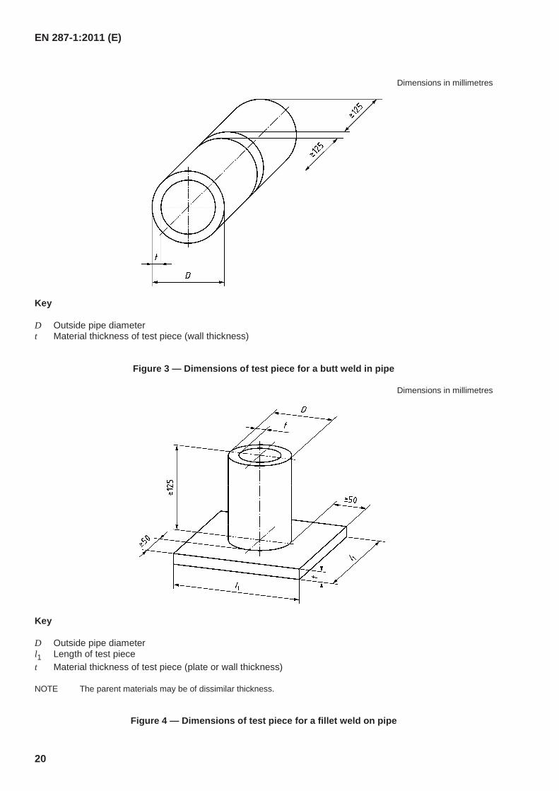
Dimensions in millimetres
Key
D Outside pipe diameter t Material thickness of test piece (wall thickness)
Figure 3 — Dimensions of test piece for a butt weld in pipe
Dimensions in millimetres
Key
D Outside pipe diameter l1 Length of test piece t Material thickness of test piece (plate or wall thickness)
NOTE The parent materials may be of dissimilar thickness.
Figure 4 — Dimensions of test piece for a fillet weld on pipe
EN 287-1:2011 (E)
21
6.3 Welding conditions
The qualification test of welders shall follow a pWPS or WPS prepared in accordance with EN ISO 15609-1 or EN ISO 15609-2. The required throat thickness of the fillet weld test piece shall be defined in the pWPS or WPS used for the test.
The following welding conditions shall apply:
the welding time for the test piece shall correspond to the working time under usual production conditions;
the examination length of the test pieces shall have at least one stop and re-start in the root run and in the capping run(s). The stop and re-starts in both root and cap runs shall be identified;
the welder shall be allowed to remove minor imperfections by grinding, except for capping run(s) for which only the stop and start may be ground; the permission of the examiner or examining body shall be obtained;
any post-welded heat treatment required in the pWPS or WPS can be omitted at the discretion of the manufacturer.
6.4 Test methods
After welding the test piece shall be tested in accordance with Table 11.
If the weld is accepted by visual testing, the additional test(s) according to Table 11 shall be carried out.
When permanent backing was used in the qualification test it shall be removed prior to destructive testing, but need not be removed before non-destructive testing (NDT).
The test specimen for macroscopic examination shall be prepared and etched on one side to clearly reveal the weld. Polishing is not required.
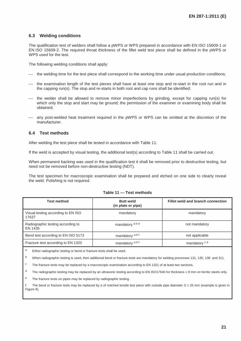
Table 11 — Test methods
Test method Butt weld (in plate or pipe)
Fillet weld and branch connection
Visual testing according to EN ISO 17637
mandatory mandatory
Radiographic testing according to EN 1435
mandatory a b d not mandatory
Bend test according to EN ISO 5173 mandatory a b f not applicable
Fracture test according to EN 1320 mandatory a b f mandatory c e
a Either radiographic testing or bend or fracture tests shall be used.
b When radiographic testing is used, then additional bend or fracture tests are mandatory for welding processes 131, 135, 138 and 311.
c The fracture tests may be replaced by a macroscopic examination according to EN 1321 of at least two sections.
d The radiographic testing may be replaced by an ultrasonic testing according to EN ISO17640 for thickness ≥ 8 mm on ferritic steels only.
e The fracture tests on pipes may be replaced by radiographic testing.
f The bend or fracture tests may be replaced by a of notched tensile test piece with outside pipe diameter D ≤ 25 mm (example is given in Figure 8).
EN 287-1:2011 (E)
22
6.5 Test piece and test specimen
6.5.1 General
In 6.5.2 to 6.5.4 details of the type, dimensions and preparation of the test pieces and test specimens are given. In addition, the requirements for destructive tests are indicated.
6.5.2 Butt weld in plate and pipe
When radiographic testing is used, the examination length of the weld (see Figures 5a), 7a) and 7b)) in the test piece shall be radiographed in the as-welded condition (no removal of excess weld metal).
When fracture testing is used, the test piece examination length shall be cut into test specimens of equal width and all of them shall be tested in such a manner that fracture occur. The examination length of each test specimen shall be ≥ 40 mm. All notch profiles according to EN 1320 are permitted.
When transverse bend testing or side bend testing is used the diameter of the former or the inner roller shall be 4 t and the bending angle 180° for parent metal with elongation A ≥ 20 %. For parent metal with elongation A < 20 %, the following equation shall apply:
ss t
At
d −×
=100
(1)
where
d is the diameter of the former or the inner roller, in mm; ts is the thickness of the bend test specimen, in mm; A is the minimum tensile elongation required by the material specification, in %.
When only transverse bend testing is carried out, the examination length shall be cut into test specimens of equal width and all of them shall be tested. When only side bend tests are used, a minimum of four test specimens shall be taken equally spaced along the examination length. One of these side bend tests shall be taken from the start and stop area in the examination length. Bend tests shall be performed in accordance with EN ISO 5173.
For thickness t > 12 mm, the transverse bend tests can be substituted by side bend tests.
When using radiography, the number of additional fracture or transverse bend test specimens for welding processes 131, 135, 138 or 311, depends on the welding position. For welding position PA or PC, one root and one face bend test specimen shall be tested (see Figure 7a). For all other welding positions, two root and two face bend test specimens shall be tested (see Figure 7b).
EN 287-1:2011 (E)
23
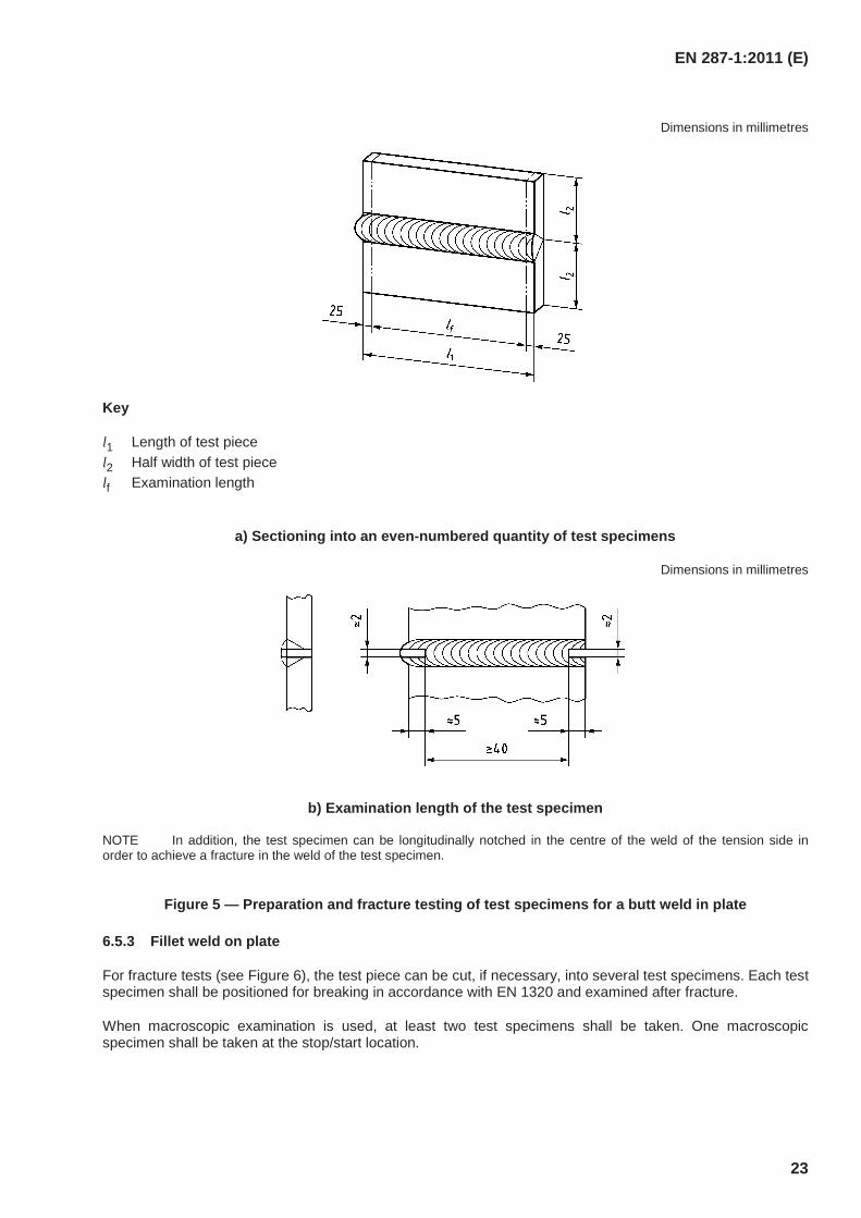
Dimensions in millimetres
Key
l1 Length of test piece l2 Half width of test piece lf Examination length
a) Sectioning into an even-numbered quantity of test specimens
Dimensions in millimetres
b) Examination length of the test specimen
NOTE In addition, the test specimen can be longitudinally notched in the centre of the weld of the tension side in order to achieve a fracture in the weld of the test specimen.
Figure 5 — Preparation and fracture testing of test specimens for a butt weld in plate
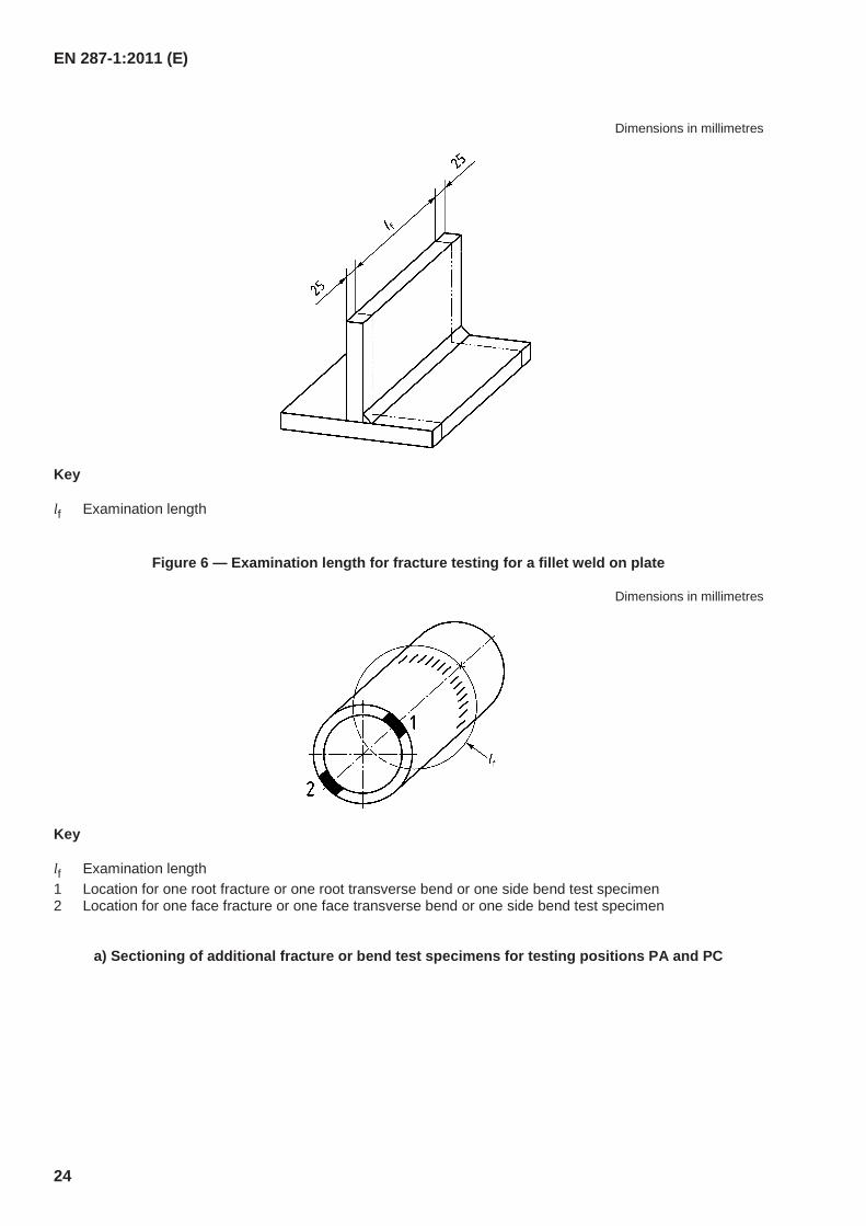
6.5.3 Fillet weld on plate
For fracture tests (see Figure 6), the test piece can be cut, if necessary, into several test specimens. Each test specimen shall be positioned for breaking in accordance with EN 1320 and examined after fracture.
When macroscopic examination is used, at least two test specimens shall be taken. One macroscopic specimen shall be taken at the stop/start location.
EN 287-1:2011 (E)
24
Dimensions in millimetres
Key
lf Examination length
Figure 6 — Examination length for fracture testing for a fillet weld on plate
Dimensions in millimetres
Key
lf Examination length 1 Location for one root fracture or one root transverse bend or one side bend test specimen 2 Location for one face fracture or one face transverse bend or one side bend test specimen
a) Sectioning of additional fracture or bend test specimens for testing positions PA and PC
EN 287-1:2011 (E)
25
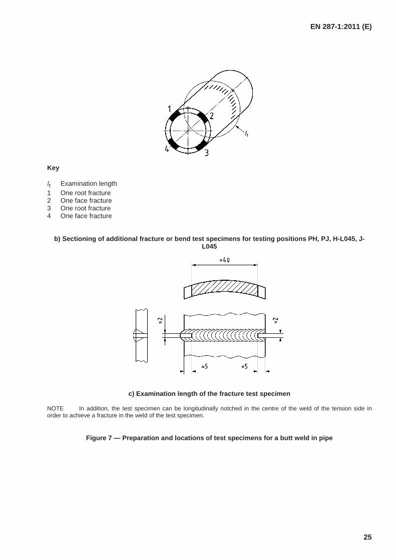
Key
lf Examination length 1 One root fracture 2 One face fracture 3 One root fracture 4 One face fracture
b) Sectioning of additional fracture or bend test specimens for testing positions PH, PJ, H-L045, J-L045
c) Examination length of the fracture test specimen
NOTE In addition, the test specimen can be longitudinally notched in the centre of the weld of the tension side in order to achieve a fracture in the weld of the test specimen.
Figure 7 — Preparation and locations of test specimens for a butt weld in pipe
EN 287-1:2011 (E)
26
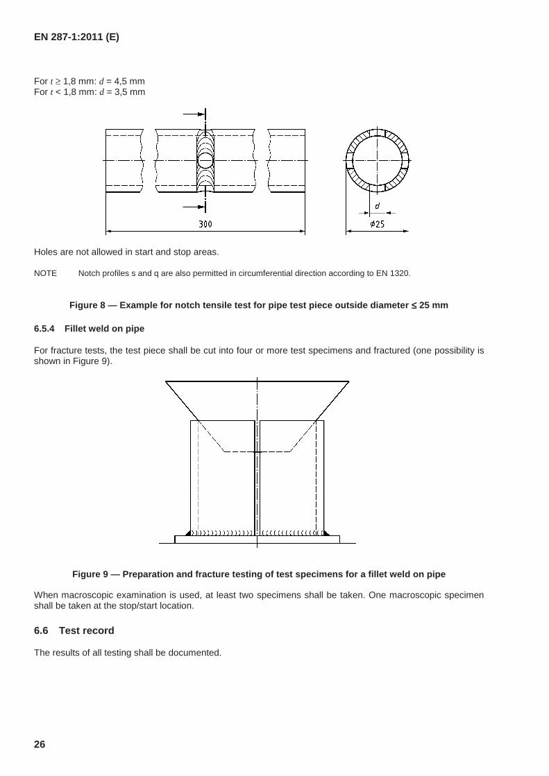
For t ≥ 1,8 mm: d = 4,5 mm For t < 1,8 mm: d = 3,5 mm
Holes are not allowed in start and stop areas.
NOTE Notch profiles s and q are also permitted in circumferential direction according to EN 1320.
Figure 8 — Example for notch tensile test for pipe test piece outside diameter ≤≤≤≤ 25 mm
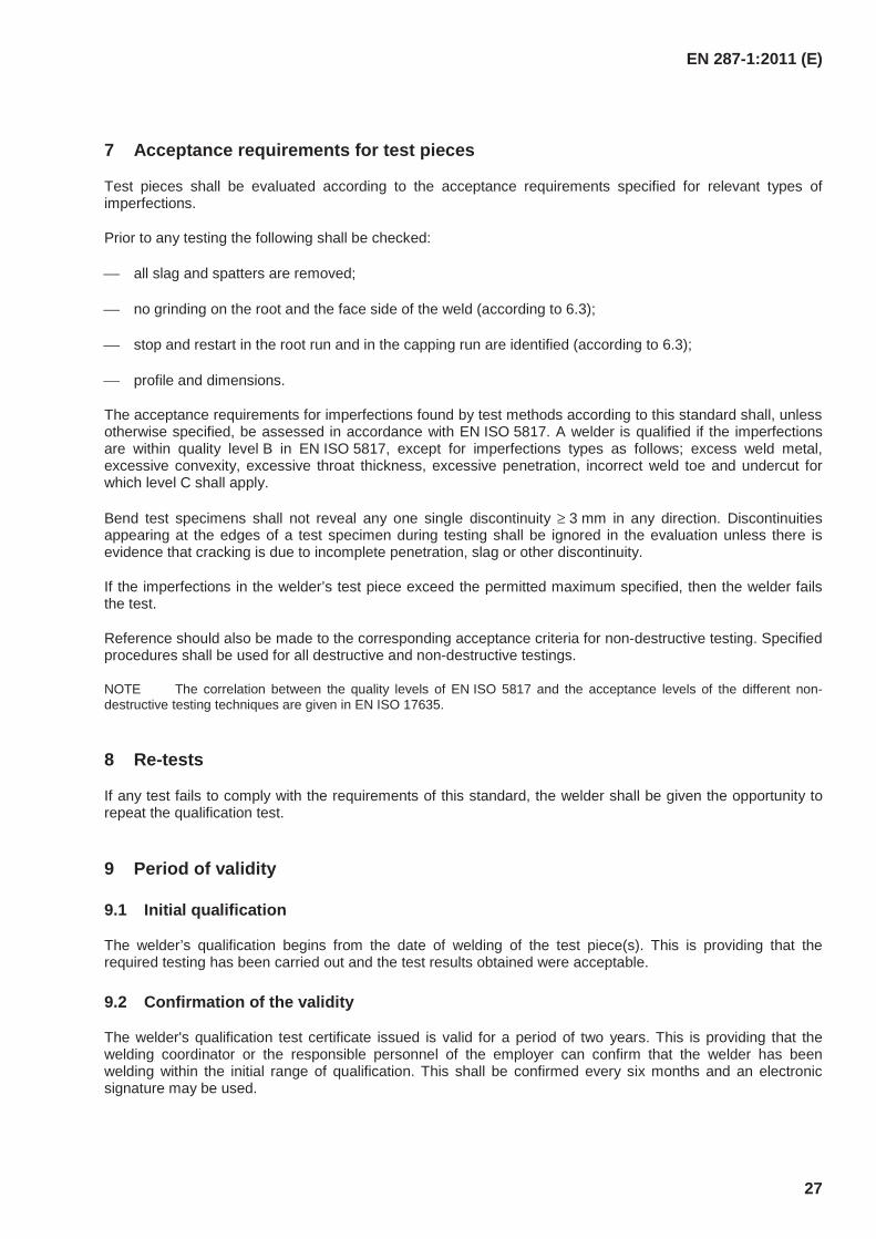
6.5.4 Fillet weld on pipe
For fracture tests, the test piece shall be cut into four or more test specimens and fractured (one possibility is shown in Figure 9).
Figure 9 — Preparation and fracture testing of test specimens for a fillet weld on pipe
When macroscopic examination is used, at least two specimens shall be taken. One macroscopic specimen shall be taken at the stop/start location.
6.6 Test record
The results of all testing shall be documented.
EN 287-1:2011 (E)
27
7 Acceptance requirements for test pieces
Test pieces shall be evaluated according to the acceptance requirements specified for relevant types of imperfections.
Prior to any testing the following shall be checked:
all slag and spatters are removed;
no grinding on the root and the face side of the weld (according to 6.3);
stop and restart in the root run and in the capping run are identified (according to 6.3);
profile and dimensions.
The acceptance requirements for imperfections found by test methods according to this standard shall, unless otherwise specified, be assessed in accordance with EN ISO 5817. A welder is qualified if the imperfections are within quality level B in EN ISO 5817, except for imperfections types as follows; excess weld metal, excessive convexity, excessive throat thickness, excessive penetration, incorrect weld toe and undercut for which level C shall apply.
Bend test specimens shall not reveal any one single discontinuity ≥ 3 mm in any direction. Discontinuities appearing at the edges of a test specimen during testing shall be ignored in the evaluation unless there is evidence that cracking is due to incomplete penetration, slag or other discontinuity.
If the imperfections in the welder’s test piece exceed the permitted maximum specified, then the welder fails the test.
Reference should also be made to the corresponding acceptance criteria for non-destructive testing. Specified procedures shall be used for all destructive and non-destructive testings.
NOTE The correlation between the quality levels of EN ISO 5817 and the acceptance levels of the different non-destructive testing techniques are given in EN ISO 17635.
8 Re-tests
If any test fails to comply with the requirements of this standard, the welder shall be given the opportunity to repeat the qualification test.
9 Period of validity
9.1 Initial qualification
The welder’s qualification begins from the date of welding of the test piece(s). This is providing that the required testing has been carried out and the test results obtained were acceptable.
9.2 Confirmation of the validity
The welder's qualification test certificate issued is valid for a period of two years. This is providing that the welding coordinator or the responsible personnel of the employer can confirm that the welder has been welding within the initial range of qualification. This shall be confirmed every six months and an electronic signature may be used.
EN 287-1:2011 (E)
28
9.3 Prolongation of qualification
Welder's qualification test certificates according to this standard can be prolonged every two years by an examiner/examining body.
Before prolongation of the certification takes place, 9.2 needs to be satisfied and also the following conditions need to be confirmed:
a) All records and evidence used to support prolongation shall be traceable to the welder and shall identify the WPS(s) used in production;
b) Evidence used to support prolongation shall be of a volumetric (radiographic testing or ultrasonic testing) or destructive nature (fracture or bends) made on two welds during the previous six months. Evidence relating to prolongation needs to be retained for a minimum of two years;
c) The welds shall satisfy the acceptance levels for imperfections as specified in Clause 7;
d) The test results mentioned in 9.3 b) shall demonstrate that the welder has reproduced the original test conditions, except for thickness and outside pipe diameter.
10 Certificate
It shall be verified that the welder has successfully passed the qualification test. All essential variables shall be recorded on the certificate. If the test piece(s) fail(s) any of the required tests, no certificate shall be issued.
The certificate shall be issued under the sole responsibility of the examiner or examining body and shall contain all information detailed in Annex A. The format of this Annex A is recommended to be used as the welder’s qualification test certificate. If any other form of welder’s qualification test certificate is used, it shall contain the information required in Annex A.
In general for each test piece a separate welder's qualification test certificate shall be issued.
If more than one test piece is welded a single welder's qualification test certificate can be issued that combines the ranges of qualification of the individual test pieces. All essential variables for both tests shall be recorded on the combined certificate. In this case, only one of the following essential variables is permitted to differ, except the samples given in 5.7:
Type of weld;
Welding position;
Material thickness.
Other essential variables are not allowed to be changed.
It is recommended to issue the welder's qualification test certificate in at least one of the languages English, French or German in combination with any other language, if necessary.
The examination of job knowledge (see Annex C) shall be designated by “Accepted” or “Not tested”.
11 Designation
The designation of a welder qualification shall comprise the following items in the order given (the system is arranged so that it can be used for computerization):
a) the number of this standard;
EN 287-1:2011 (E)
29
b) the essential variables;
c) welding processes: refer to 4.2, 5.2 and EN ISO 4063;
d) product type: plate (P), pipe (T), refer to 4.3.1 and 5.3;
e) type of weld: butt weld (BW), fillet weld (FW), refer to 5.4;
f) material group: refer to 5.5;
g) filler materials: refer to 5.6;
h) dimensions of test piece: material thickness t and outside pipe diameter D, refer to 5.7;
i) welding positions: refer to 5.8 and EN ISO 6947;
j) weld details: refer to 5.9.
The type of shielding and backing gas shall not be incorporated in the designation but shall be included in the welder’s qualification test certificate (see Annex A).
Designation examples are shown in Annex B.
EN 287-1:2011 (E)
30
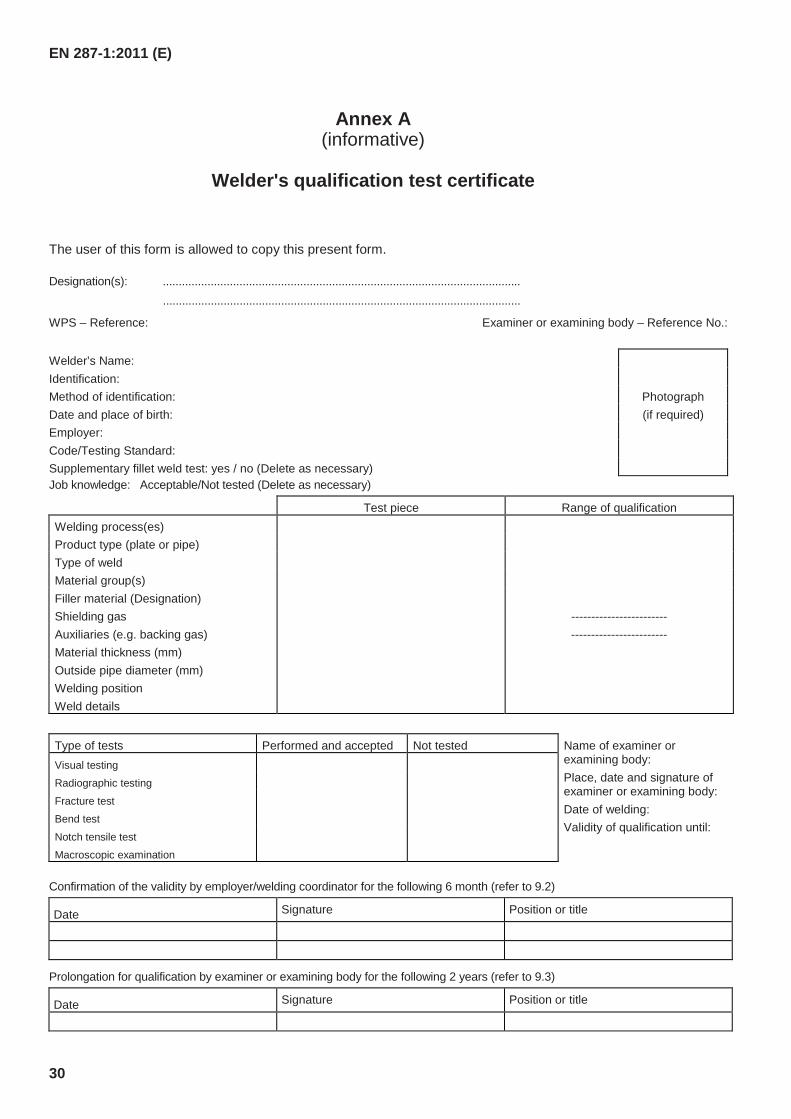
Annex A (informative)
Welder's qualification test certificate
The user of this form is allowed to copy this present form.
Designation(s): ................................................................................................................ ................................................................................................................
WPS – Reference: Examiner or examining body – Reference No.:
Welder’s Name: Identification: Method of identification: Photograph Date and place of birth: (if required) Employer: Code/Testing Standard: Supplementary fillet weld test: yes / no (Delete as necessary) Job knowledge: Acceptable/Not tested (Delete as necessary)
Test piece Range of qualification Welding process(es) Product type (plate or pipe) Type of weld Material group(s) Filler material (Designation) Shielding gas ------------------------ Auxiliaries (e.g. backing gas) ------------------------ Material thickness (mm) Outside pipe diameter (mm) Welding position Weld details
Type of tests Performed and accepted Not tested Name of examiner or examining body: Place, date and signature of examiner or examining body: Date of welding: Validity of qualification until:
Visual testing
Radiographic testing
Fracture test Bend test Notch tensile test Macroscopic examination
Confirmation of the validity by employer/welding coordinator for the following 6 month (refer to 9.2)
Date Signature Position or title
Prolongation for qualification by examiner or examining body for the following 2 years (refer to 9.3)
Date Signature Position or title
EN 287-1:2011 (E)
31
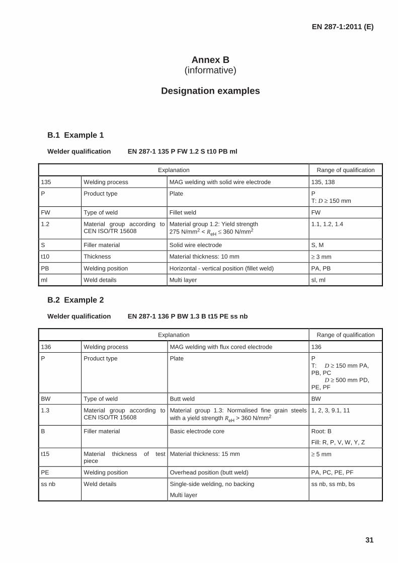
Annex B (informative)
Designation examples
B.1 Example 1
Welder qualification EN 287-1 135 P FW 1.2 S t10 PB ml
Explanation Range of qualification
135 Welding process MAG welding with solid wire electrode 135, 138
P Product type Plate P T: D ≥ 150 mm
FW Type of weld Fillet weld FW
1.2 Material group according to CEN ISO/TR 15608
Material group 1.2: Yield strength 275 N/mm2 < ReH ≤ 360 N/mm2
1.1, 1.2, 1.4
S Filler material Solid wire electrode S, M
t10 Thickness Material thickness: 10 mm ≥ 3 mm
PB Welding position Horizontal - vertical position (fillet weld) PA, PB
ml Weld details Multi layer sl, ml
B.2 Example 2
Welder qualification EN 287-1 136 P BW 1.3 B t15 PE ss nb
Explanation Range of qualification
136 Welding process MAG welding with flux cored electrode 136
P Product type Plate P T: D ≥ 150 mm PA, PB, PC D ≥ 500 mm PD, PE, PF
BW Type of weld Butt weld BW
1.3 Material group according to CEN ISO/TR 15608
Material group 1.3: Normalised fine grain steels with a yield strength ReH > 360 N/mm2
1, 2, 3, 9.1, 11
B Filler material Basic electrode core Root: B
Fill: R, P, V, W, Y, Z
t15 Material thickness of test piece
Material thickness: 15 mm ≥ 5 mm
PE Welding position Overhead position (butt weld) PA, PC, PE, PF
ss nb Weld details Single-side welding, no backing
Multi layer
ss nb, ss mb, bs
EN 287-1:2011 (E)
32
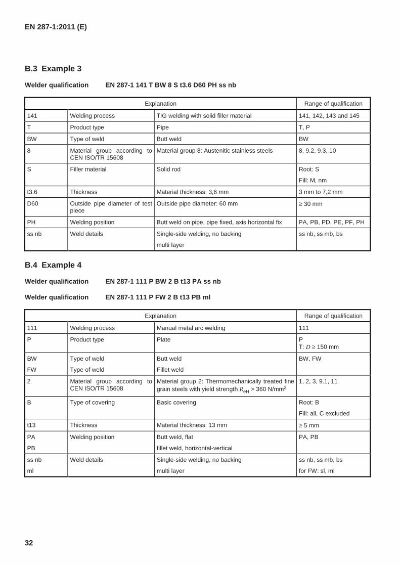
B.3 Example 3
Welder qualification EN 287-1 141 T BW 8 S t3.6 D60 PH ss nb
Explanation Range of qualification
141 Welding process TIG welding with solid filler material 141, 142, 143 and 145
T Product type Pipe T, P
BW Type of weld Butt weld BW
8 Material group according to CEN ISO/TR 15608
Material group 8: Austenitic stainless steels 8, 9.2, 9.3, 10
S Filler material Solid rod Root: S
Fill: M, nm
t3.6 Thickness Material thickness: 3,6 mm 3 mm to 7,2 mm
D60 Outside pipe diameter of test piece
Outside pipe diameter: 60 mm ≥ 30 mm
PH Welding position Butt weld on pipe, pipe fixed, axis horizontal fix PA, PB, PD, PE, PF, PH
ss nb Weld details Single-side welding, no backing
multi layer
ss nb, ss mb, bs
B.4 Example 4
Welder qualification EN 287-1 111 P BW 2 B t13 PA ss nb
Welder qualification EN 287-1 111 P FW 2 B t13 PB ml
Explanation Range of qualification
111 Welding process Manual metal arc welding 111
P Product type Plate P T: D ≥ 150 mm
BW
FW
Type of weld
Type of weld
Butt weld
Fillet weld
BW, FW
2 Material group according to CEN ISO/TR 15608
Material group 2: Thermomechanically treated fine grain steels with yield strength ReH > 360 N/mm2
1, 2, 3, 9.1, 11
B Type of covering Basic covering Root: B
Fill: all, C excluded
t13 Thickness Material thickness: 13 mm ≥ 5 mm
PA
PB
Welding position Butt weld, flat
fillet weld, horizontal-vertical
PA, PB
ss nb
ml
Weld details
Single-side welding, no backing
multi layer
ss nb, ss mb, bs
for FW: sl, ml
EN 287-1:2011 (E)
33
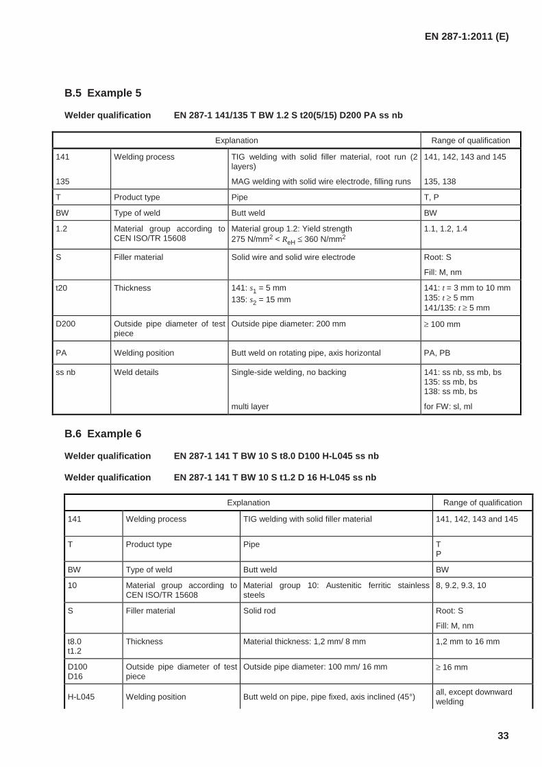
B.5 Example 5
Welder qualification EN 287-1 141/135 T BW 1.2 S t20(5/15) D200 PA ss nb
Explanation Range of qualification
141
135
Welding process TIG welding with solid filler material, root run (2 layers)
MAG welding with solid wire electrode, filling runs
141, 142, 143 and 145
135, 138
T Product type Pipe T, P
BW Type of weld Butt weld BW
1.2 Material group according to CEN ISO/TR 15608
Material group 1.2: Yield strength 275 N/mm2 < ReH ≤ 360 N/mm2
1.1, 1.2, 1.4
S Filler material Solid wire and solid wire electrode Root: S
Fill: M, nm
t20 Thickness 141: s1 = 5 mm 135: s2 = 15 mm
141: t = 3 mm to 10 mm 135: t ≥ 5 mm 141/135: t ≥ 5 mm
D200 Outside pipe diameter of test piece
Outside pipe diameter: 200 mm ≥ 100 mm
PA Welding position Butt weld on rotating pipe, axis horizontal PA, PB
ss nb Weld details
Single-side welding, no backing
multi layer
141: ss nb, ss mb, bs 135: ss mb, bs 138: ss mb, bs
for FW: sl, ml
B.6 Example 6
Welder qualification EN 287-1 141 T BW 10 S t8.0 D100 H-L045 ss nb
Welder qualification EN 287-1 141 T BW 10 S t1.2 D 16 H-L045 ss nb
Explanation Range of qualification
141
Welding process TIG welding with solid filler material 141, 142, 143 and 145
T Product type Pipe T P
BW Type of weld Butt weld BW
10 Material group according to CEN ISO/TR 15608
Material group 10: Austenitic ferritic stainless steels
8, 9.2, 9.3, 10
S Filler material Solid rod Root: S
Fill: M, nm
t8.0 t1.2
Thickness Material thickness: 1,2 mm/ 8 mm 1,2 mm to 16 mm
D100 D16
Outside pipe diameter of test piece
Outside pipe diameter: 100 mm/ 16 mm ≥ 16 mm
H-L045 Welding position Butt weld on pipe, pipe fixed, axis inclined (45°) all, except downward welding
EN 287-1:2011 (E)
34
Explanation Range of qualification
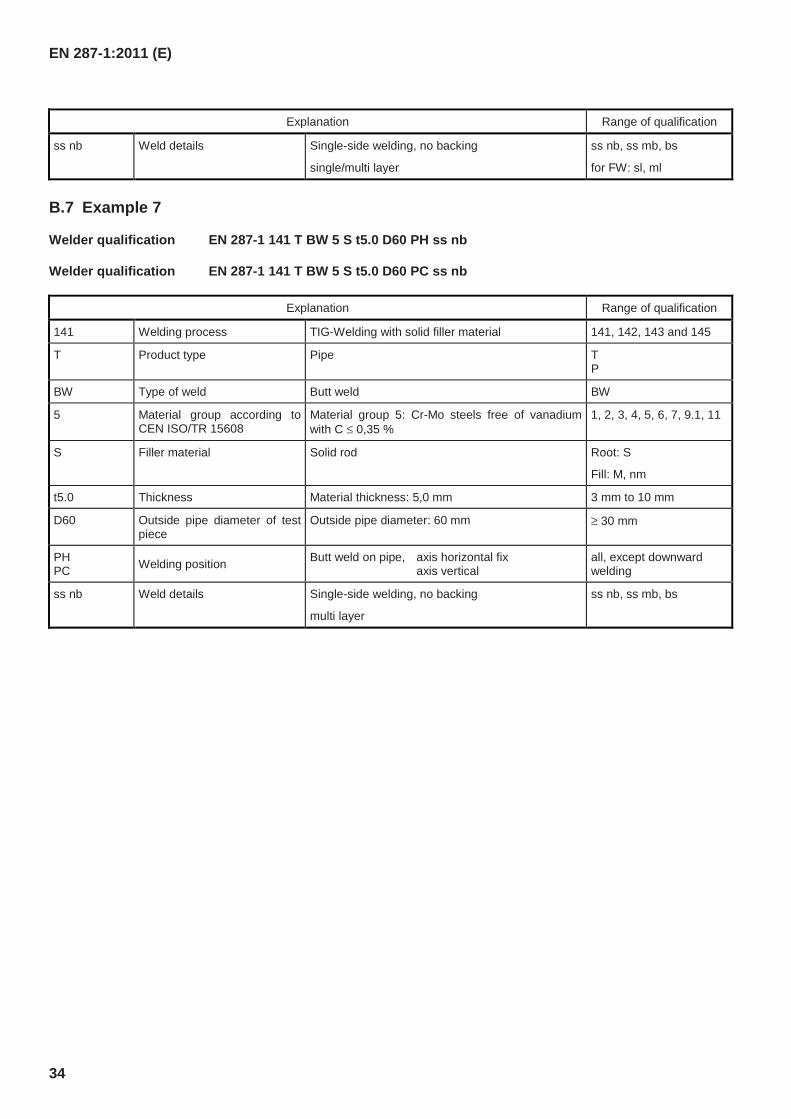
ss nb Weld details
Single-side welding, no backing
single/multi layer
ss nb, ss mb, bs
for FW: sl, ml
B.7 Example 7
Welder qualification EN 287-1 141 T BW 5 S t5.0 D60 PH ss nb
Welder qualification EN 287-1 141 T BW 5 S t5.0 D60 PC ss nb
Explanation Range of qualification
141 Welding process TIG-Welding with solid filler material 141, 142, 143 and 145
T Product type Pipe T P
BW Type of weld Butt weld BW
5 Material group according to CEN ISO/TR 15608
Material group 5: Cr-Mo steels free of vanadium with C ≤ 0,35 %
1, 2, 3, 4, 5, 6, 7, 9.1, 11
S Filler material Solid rod Root: S
Fill: M, nm
t5.0 Thickness Material thickness: 5,0 mm 3 mm to 10 mm
D60 Outside pipe diameter of test piece
Outside pipe diameter: 60 mm ≥ 30 mm
PH PC Welding position Butt weld on pipe, axis horizontal fix
axis vertical all, except downward welding
ss nb Weld details
Single-side welding, no backing
multi layer
ss nb, ss mb, bs
EN 287-1:2011 (E)
35
Annex C (informative)
Job knowledge
C.1 General
The test of job knowledge is recommended, but it is not mandatory.
However, some countries can require that the welder undergoes a test of job knowledge. If the job knowledge test is carried out, it should be recorded on the welder’s qualification test certificate.
This annex outlines the job knowledge that a welder should have to ensure that procedures are followed and common practices are complied with. The job knowledge indicated in this annex is only pitched at the most basic level.
Owing to different training programmes in various countries, it is only proposed to standardize general objectives or categories of job knowledge. The actual question used should be drawn up by the individual country, but should include questions on areas covered in C.2, relevant to the qualification test of welders.
The actual tests of a welder’s job knowledge can be given by any of the following methods or combinations of these methods:
a) written objective tests (multiple choice);
b) oral questioning following a set of written questions;
c) computer testing;
d) demonstration/observation testing following a written set of criteria.
The test of job knowledge is limited to the matters related to the welding process used in the test.
C.2 Requirements
C.2.1 Welding equipment
C.2.1.1 Oxy-acetylene welding
a) Identification of gas cylinders;
b) Identification and assembly of essential components;
c) Selection of correct nozzles and welding torches.
C.2.1.2 Arc welding
a) Construction and maintenance of welding equipment and typical parameters;
b) Type of welding current;
c) Correct connection of the welding return cable.
EN 287-1:2011 (E)
36
C.2.2 Welding process 2)
C.2.2.1 Oxy-acetylene welding (311)
a) Gas pressure;
b) Selection of nozzle type;
c) Type of gas flame;
d) Effect of overheating.
C.2.2.2 Manual metal arc welding (111)
a) Classification of electrodes.
C.2.2.3 Gas and self-shielded metal arc welding (114, 13, 14, 15)
a) Types and size of electrodes;
b) Identification of shielding gas and flow rate (without 114);
c) Type, size and maintenance of nozzles/contact tip;
d) Selection and limitations of mode of metal transfer;
e) Protection of the welding arc from draughts.
C.2.2.4 Submerged arc welding (121, 125)
a) Drying, feeding and correct recovery of flux;
b) Correct alignment and travel of welding head.
C.2.3 Parent metals
a) Identification of material;
b) Methods and control of pre-heating;
c) Control of interpass temperature.
C.2.4 Welding consumables
a) Identification of welding consumables;
b) Storage, handling and conditions of welding consumables;
c) Selection of correct size;
d) Cleanliness of electrodes and filler wires;
e) Control of wire spooling;
2) The numbers refer to EN ISO 4063.
EN 287-1:2011 (E)
37
f) Control and monitoring of gas flow rates and quality.
C.2.5 Safety precautions
C.2.5.1 General
a) Safe assembly, setting up and turn off procedures;
b) Safe control of welding fumes and gases;
c) Personal protection;
d) Fire hazards;
e) Welding in confined spaces;
f) Awareness of welding environment.
C.2.5.2 Oxy-acetylene welding
a) Safe storage, handling and use of compressed gases;
b) Leak detection on gas hoses and fittings;
c) Procedure to be taken in the event of a flashback.
C.2.5.3 All arc welding processes
a) Environment of increase hazard electric shock;
b) Radiation from the arc;
c) Effects of stray arcing.
C.2.5.4 Gas-shielded metal arc welding
a) Safe storage, handling and use of compressed gases;
b) Leak detection on gas hoses and fittings.
C.2.6 Welding sequences/procedures
Appreciation of welding procedure requirements and the influence of welding parameters.
C.2.7 Joint preparation and weld representation
a) Conformance of joint preparation to the welding procedure specification (WPS);
b) Cleanliness of fusion faces.
C.2.8 Weld imperfections
a) Identification of imperfections;
b) Causes;
c) Prevention and remedial action.
EN 287-1:2011 (E)
38
C.2.9 Welder qualification
The welder should be aware of the range of the qualification.
EN 287-1:2011 (E)
39
Annex ZA (informative)
Relationship between this European Standard and the Essential
Requirements of EC Directive 97/23/EC
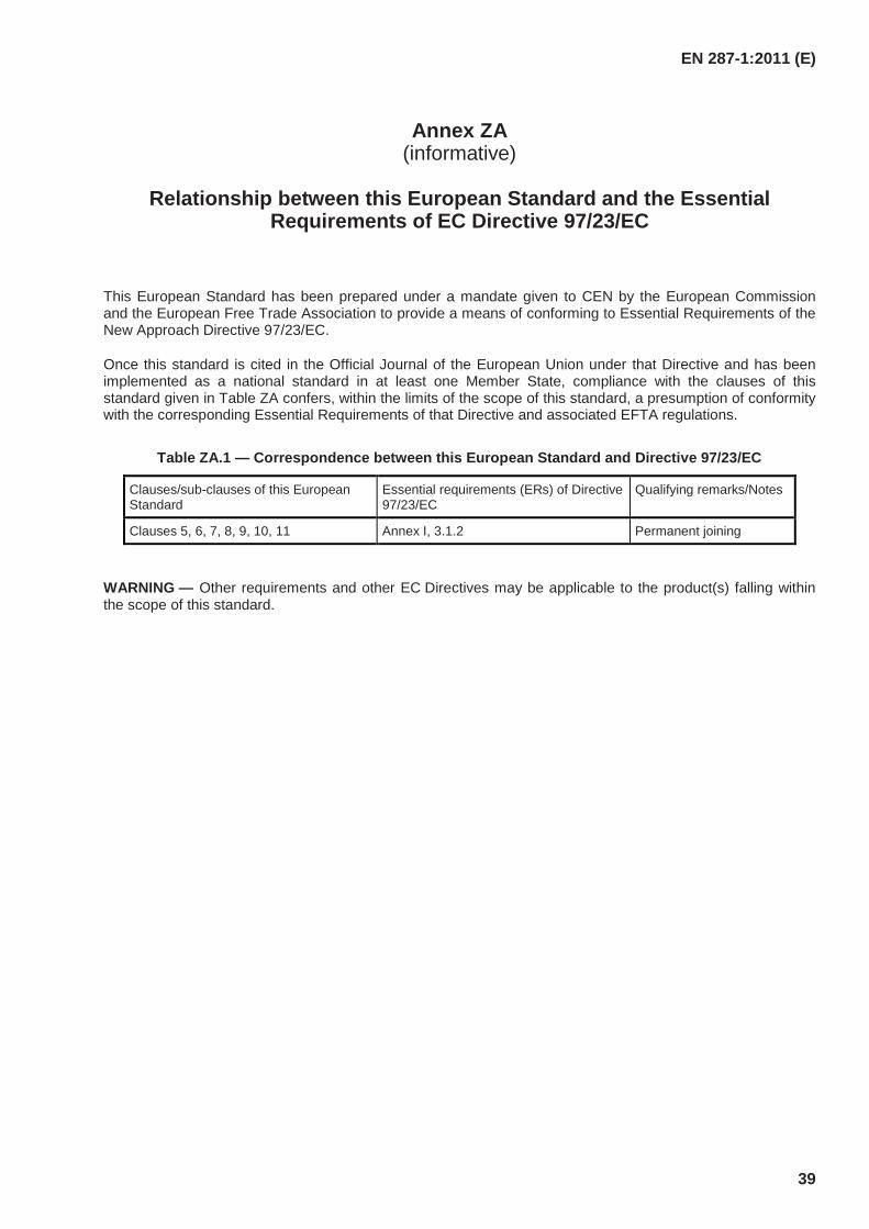
This European Standard has been prepared under a mandate given to CEN by the European Commission and the European Free Trade Association to provide a means of conforming to Essential Requirements of the New Approach Directive 97/23/EC.
Once this standard is cited in the Official Journal of the European Union under that Directive and has been implemented as a national standard in at least one Member State, compliance with the clauses of this standard given in Table ZA confers, within the limits of the scope of this standard, a presumption of conformity with the corresponding Essential Requirements of that Directive and associated EFTA regulations.
Table ZA.1 — Correspondence between this European Standard and Directive 97/23/EC
Clauses/sub-clauses of this European Standard
Essential requirements (ERs) of Directive 97/23/EC
Qualifying remarks/Notes
Clauses 5, 6, 7, 8, 9, 10, 11 Annex I, 3.1.2 Permanent joining
WARNING — Other requirements and other EC Directives may be applicable to the product(s) falling within the scope of this standard.
EN 287-1:2011 (E)
40
Bibliography
[1] EN 1321, Destructive tests on welds in metallic materials — Macroscopic and microscopic examination of welds
[2] EN 1418, Welding personnel — Approval testing of welding operators for fusion welding and resistance weld setters for fully mechanized and automatic welding of metallic materials
[3] EN 22553, Welded, brazed and soldered joints — Symbolic representation on drawings (ISO 2553:1992)
[4] EN ISO 17635, Non-destructive testing of welds — General rules for metallic materials (ISO 17635:2010)
[5] EN ISO 17640, Non-destructive testing of welds — Ultrasonic testing —Techniques, testing levels, and assessment (ISO 17640:2010)
[6] EN ISO 2560, Welding consumables — Covered electrodes for manual metal arc welding of non-alloy and fine grain steels — Classification (ISO 2560:2009)
[7] EN ISO 9000:2005, Quality management systems — Fundamentals and vocabulary (ISO 9000:2005)
[8] EN ISO 15607:2003, Specification and qualification of welding procedures for metallic materials — General rules (ISO 15607:2003)
[9] EN ISO 15614-1, Specification and qualification of welding procedures for metallic materials — Welding procedure test — Part 1: Arc and gas welding of steels and arc welding of nickel and nickel alloys (ISO 15614-1:2004)
[10] EN ISO 17632, Welding consumables — Tubular cored electrodes for gas shielded and non-gas shielded metal arc welding of non-alloy and fine grain steels — Classification (ISO 17632:2004)
[11] EN ISO 17635, Non-destructive testing of welds — General rules for metallic materials (ISO 17635:2010)
[12] CEN ISO/TR 20172, Welding — Grouping systems for materials — European materials
[13] CEN ISO/TR 20173, Welding — Grouping systems for materials — American materials
[14] CEN ISO/TR 20174, Welding — Grouping systems for materials — Japanese materials
[15] ISO 857-1, Welding and allied processes — Vocabulary — Part 1: Metal welding processes
[16] ISO/TR 25901:2007, Welding and related processes — Vocabulary

blank
BS EN 287-1:2011
BSI
389 Chiswick High Road
London
W4 4AL
BSI — British Standards Institution
BSI is the independent national body responsible for preparing British Standards. It presents the UK view on standards in Europe and at the international level. It is incorporated by Royal Charter.
Revisions
British Standards are updated by amendment or revision. Users of British Standards should make sure that they possess the latest amendments or editions.
It is the constant aim of BSI to improve the quality of our products and services. We would be grateful if anyone finding an inaccuracy or ambiguity while using this British Standard would inform the Secretary of the technical committee responsible, the identity of which can be found on the inside front cover. Tel: +44 (0)20 8996 9000. Fax: +44 (0)20 8996 7400.
BSI offers members an individual updating service called PLUS which ensures that subscribers automatically receive the latest editions of standards.
Buying standards
Orders for all BSI, international and foreign standards publications should be addressed to Customer Services. Tel: +44 (0)20 8996 9001. Fax: +44 (0)20 8996 7001. Email: [email protected]. Standards are also available from the BSI website at http://www.bsi-global.com.
In response to orders for international standards, it is BSI policy to supply the BSI implementation of those that have been published as British Standards, unless otherwise requested.
Information on standards
BSI provides a wide range of information on national, European and international standards through its Library and its Technical Help to Exporters Service. Various BSI electronic information services are also available which give details on all its products and services. Contact the Information Centre. Tel: +44 (0)20 8996 7111. Fax: +44 (0)20 8996 7048. Email: [email protected].
Subscribing members of BSI are kept up to date with standards developments and receive substantial discounts on the purchase price of standards. For details of these and other benefits contact Membership Administration. Tel: +44 (0)20 8996 7002. Fax: +44 (0)20 8996 7001. Email: [email protected].
Information regarding online access to British Standards via British Standards Online can be found at http://www.bsi-global.com/bsonline.
Further information about BSI is available on the BSI website at http://www.bsi-global.com.
Copyright
Copyright subsists in all BSI publications. BSI also holds the copyright, in the UK, of the publications of the international standardization bodies. Except as permitted under the Copyright, Designs and Patents Act 1988 no extract may be reproduced, stored in a retrieval system or transmitted in any form or by any means – electronic, photocopying, recording or otherwise – without prior written permission from BSI.
This does not preclude the free use, in the course of implementing the standard, of necessary details such as symbols, and size, type or grade designations. If these details are to be used for any other purpose than implementation then the prior written permission of BSI must be obtained.
Details and advice can be obtained from the Copyright & Licensing Manager. Tel: +44 (0)20 8996 7070. Fax: +44 (0)20 8996 7553. Email: [email protected].