Embed Size (px)
Citation preview
A Miniature Mobile Parts Feeder:
Operating Principles and Simulation Results
Arthur E. Quaid
October, 1998
CMU-RI-TR-98-26
The Robotics InstituteCarnegie Mellon University
Pittsburgh, PA
c Carnegie Mellon University 1998
This work is supported in part by NSF grants DMI-9523156 and CDA-9503992. The author is supported in part by an AT&T FoundationGraduate Fellowship.

Abstract
In this work, a miniature mobile vibratory parts feeder is proposed.
This feeder, exploiting the unique capabilities of a recently developed
closed-loop planar linear motor, is designed to reorient, singulate, and
position parts using only horizontal vibrations. The actuators used for
generating the feed vibrations are also capable of large planar motions,
allowing the feeder to serve multiple overhead robots. This feeder is
designed with a minimum of critical physical dimensions, allowing
di�erent parts to be fed with only software changes. The basic feed
principle is presented, followed by experimental veri�cation. Finally,
a model for the motion of parts on the complete feeder is derived and
simulation results are presented.
i

ii
Contents
1 Introduction 1
1.1 Application example . . . . . . . . . . . . . . . . . . . . . . . 2
2 Feeding principle 4
2.1 Parts feeding with a stick-slip waveform . . . . . . . . . . . . 42.2 Parts feeding with a Coulomb pump waveform . . . . . . . . . 8
3 Ramps for singulation 11
4 A miniature mobile parts feeder 17
4.1 Dynamic model . . . . . . . . . . . . . . . . . . . . . . . . . . 184.2 Simulation results . . . . . . . . . . . . . . . . . . . . . . . . . 21
5 Discussion 23
References 25
iii

iv
1 Introduction
This work presents the operating principles and simulation results of a novelparts feeder. This feeder is built upon recently developed closed-loop planarlinear motor technology [1, 2], and is designed to accept bulk parts, singulateand reorient them, and present them to overhead assembly robots. Thenovelty is the ability of the feeder to move itself so that it can supply multipleoverhead robots with parts, even if their workspaces do not overlap. It alsohas a high degree of programmability and an extremely compact size.
Of course, parts feeding is of critical importance in automated assem-bly, and has therefore received much attention. Successful commercial bulkfeeders include vibratory feeder bowls, the Adept exible feeder [3], and theSony APOS system [4]. It is interesting to note that all these systems havein common a recirculation path, reorientation facility, and sorting capability.Instead of focusing on each part individually, these feeders provide mecha-nisms for some of the parts to assume the desired orientations, and allowthe rest of the parts to be recirculated. Ensuring the parts are in the properorientation may be done by mechanical means, such as bowl feeder gates orthe Sony APOS tray detents, or through sensing, as in the Adept exiblefeeder vision system.
Many have explored methods for parts feeding using vibratory devicesthat are less parts-speci�c than bowl feeders. The Dyna-Glide system [5]uses a carpet of polypropylene �bers inclined so that parts tend to feed in acertain direction when the base is vibrated. Di�erent patches of fabric arelaid out to form a conveying system with the desired feed path. Transverseoscillations of a featureless horizontal plate have been used [6] to orient andlocalize parts by setting up vibrational nodes to which parts are attracted. Inthis manner, parts can be positioned and oriented in the plane using a singleactuator and no sensors. It has also been shown [7] that horizontal vibrationsof a featureless horizontal plate can be used to move parts in the plane.Surprisingly, this technique was extended [8] to independently control thefeed directions of multiple parts sitting on the same plate by using sequencesof these horizontal vibrations. The proposed feeder, discussed shortly, useshorizontal vibrations similar to [7], but applied to a recirculating feeder designrather than for controlling the motions of speci�c parts.
1
2-DOF overhead
manipulators
courier
robots mobile parts feeder
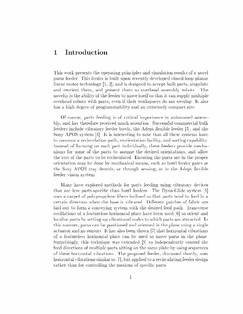
Figure 1: A miniature mobile parts feeder in a Minifactory setting: a singlefeeder supplies parts to multiple low-DOF overhead manipulators.
1.1 Application example
For motivation, an application example will be presented before discussingfurther details of the feeder. The author's particular interest in this feederis for use in the Minifactory system [9]. This system, depicted in Fig. 1consists of a series of tabletop platen tiles connected together to form anextended workspace for courier robots, which are closed-loop planar linearmotors designed to carry product sub-assemblies. The planar linear motorshave a single moving part, ride on air bearings, and can translate large dis-tances along the platen surface (limited only by the length of the tether) androtate in the plane by a few degrees. Overhead devices such as simple 2-DOF manipulators, glue dispensers, laser welders, etc. are mounted on �xedbridges above the platens. The couriers move the product from one overheaddevice to another, cooperating with the overhead devices to perform 4-DOFassembly operations.
The overhead manipulators do not have large workspaces, so parts must
be fed close to the assembly locations. In this context, it would be very usefulto have a mobile parts feeder that can move under the manipulator with anoriented part, allow the manipulator to pick it up, and then move away so
2
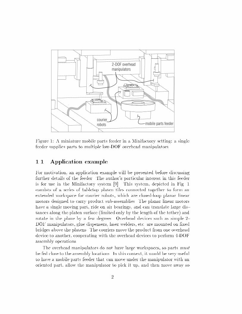
slope change
for singulation
reorientation
dropoff
sensing/
pickup
area
Figure 2: A miniature mobile parts feeder, consisting of a partially slopedannular feed tray (outside edge partially omitted for illustrative purposes)mounted on a planar robot.
that a courier with a sub-assembly can receive the part.
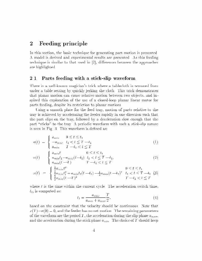
The proposed mobile parts feeder is depicted in Fig. 2. Physically, it con-sists of a specially shaped feed tray rigidly attached to a planar linear motor.The tray has an annular feed path for parts, with a sloped ramp section, and a at plateau section. Exploiting the small rotational capabilities of the motor,the feeder performs a rotational vibration resulting in a counter-clockwisemotion of the parts. When bulk parts are loaded at the bottom of the ramp,parts slowly climb the ramp, but only near the outside edge, resulting in asingle-�le line. Once in the plateau section, the parts speed up and spreadout. They continue to move around the plateau, where an overhead visionsystem can be used to identify parts in the correct orientation.1 Incorrectlyoriented parts are reoriented as they pass over the dropo� and return to thepile of bulk parts.
1It is also possible to place indentations, fences, etc. in the plateau region to separate
parts in the correct orientation without the use of vision. However, unless a removable
insert contains all the part speci�c features, the feeder's exibility will be compromised.
3
2 Feeding principle
In this section, the basic technique for generating part motion is presented.A model is derived and experimental results are presented. As this feedingtechnique is similar to that used in [7], di�erences between the approachesare highlighted.
2.1 Parts feeding with a stick-slip waveform
There is a well-known magician's trick where a tablecloth is removed fromunder a table setting by quickly jerking the cloth. This trick demonstratesthat planar motion can cause relative motion between two objects, and in-spired this exploration of the use of a closed-loop planar linear motor forparts feeding, despite its restriction to planar motions.
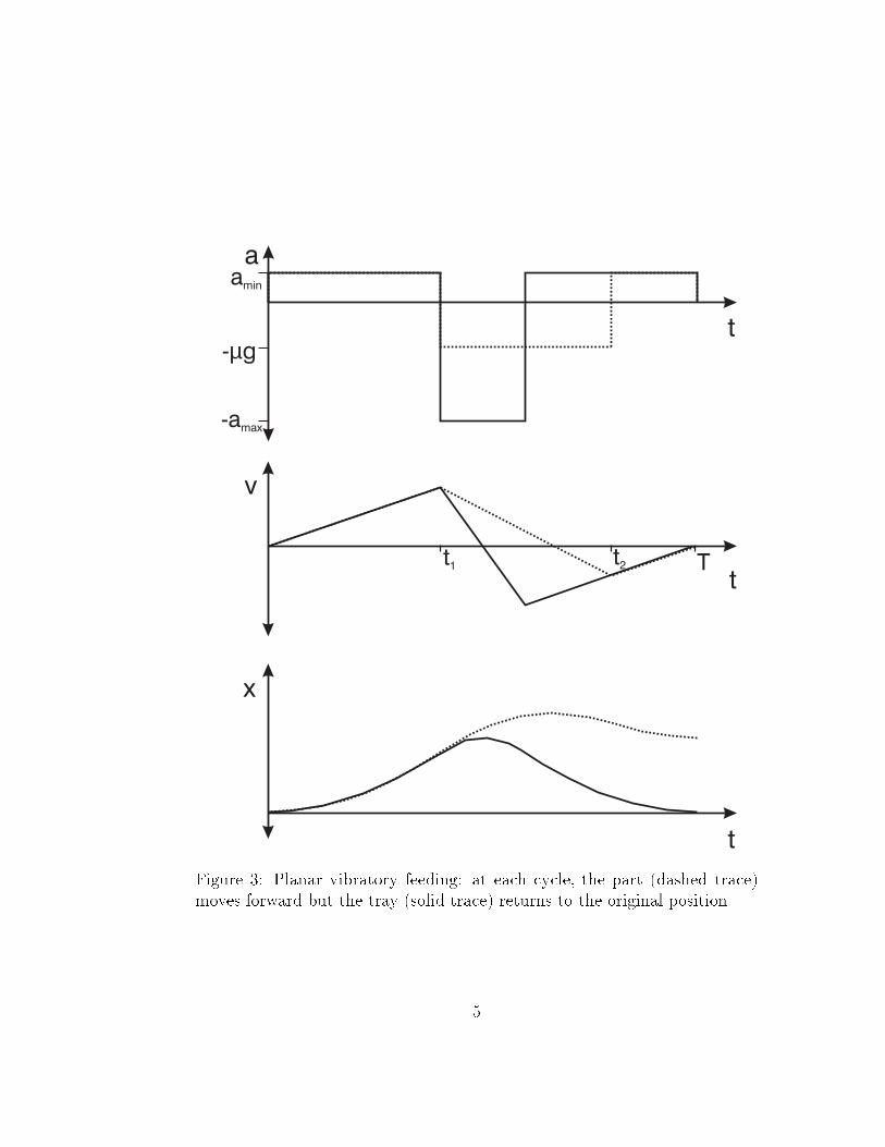
Using a smooth plate for the feed tray, motion of parts relative to thetray is achieved by accelerating the feeder rapidly in one direction such thatthe part slips on the tray, followed by a deceleration slow enough that thepart \sticks" to the tray. A periodic waveform with such a stick-slip natureis seen in Fig. 3. This waveform is de�ned as:
a(t) =
8><>:
amin 0 � t � t1�amax t1 < t � T � t1amin T � t1 < t � T
(1)
v(t) =
8><>:
amint 0 � t � t1amint1�amax(t�t1) t1 < t � T � t1;amin(t� T ) T � t1 < t � T
(2)
x(t) =
8><>:
1
2amint
2 0 � t � t11
2amint
2
1+ amint1(t� t1)�
1
2amax(t� t1)2 t1 < t � T � t1
1
2amin(t� T )2 T � t1 < t � T
;(3)
where t is the time within the current cycle. The acceleration switch time,t1, is computed as:
t1 =amax
amin + amax
T
2; (4)
based on the constraint that the velocity should be continuous. Note thatx(T )�x(0) = 0, and the feeder has no net motion. The remaining parametersof the waveform are the period T , the acceleration during the slip phase amax,and the acceleration during the stick phase amin. The choice of T should keep
4
a
v
x
t
t
t
amin
-amax
- gµ
t1 t2 T
Figure 3: Planar vibratory feeding: at each cycle, the part (dashed trace)moves forward but the tray (solid trace) returns to the original position.
5
the waveform frequency low enough to be in the dynamic range of the robot,but high enough to limit the velocities and displacements required of thefeeder. For slipping and sticking to occur, amax and amin should be chosen tomeet the constraints amax > �g and amin < �g, where g is the gravitationalacceleration and � is the coe�cient of friction between the part and feed tray.
Assuming the part is sticking to the tray at the start of the waveformand its motion is restricted to the direction of tray motion (i.e. no rolling ortransverse motion), the part will move as:
ap(t) =
8><>:
amin 0 � t � t1��g t1 < t � t2amin t2 < t � T
(5)
vp(t) =
8><>:
amint 0 � t � t1amint1 � �g(t� t1) t1 < t � t2amin(t� T ) t2 < t � T:
(6)
xp(t) =
8>>><>>>:
1
2amint
2 0 � t � t11
2amint
2
1+ amint1(t� t1) �
1
2�g(t� t1)2 t1 < t � t2
�1
2amint
2
1+ amint1t2 �
1
2�gt2
2+ �gt2t1 �
1
2�gt2
1+ t2 < t � T
(amint1 � �gt2 + �gt1)(t� t2) +1
2amin(t� t2)2
:(7)
The part catches up to the tray at time
t2 = t1 +aminT
�g + amin
; (8)
and the average part velocity over one waveform, vp, is computed as:
vp =Tamin
2
0@ �1
1 + amin�g
+1
1 + aminamax
1A : (9)
To verify the feeding principle, the waveform of Eqs. 1-3 was used asthe input to one axis of a 3-DOF PD controller controlling a planar linearmotor. Parts such as coins, rubber grommets, and plastic pieces with varyingfriction coe�cients were placed on a at feed tray attached to the motor.Although it was possible to �nd waveforms that would feed the parts well,not all theoretically acceptable waveforms worked. To investigate further, aninterferometer retrore ector cube was used as the 'part'. The interferometerwas used to measure the part position, while the motor position was measuredby the integral planar linear motor sensors. Both measurements were precise
6
0 0.02 0.04 0.06 0.08 0.1 0.12 0.14 0.16 0.18 0.2
−60
−40
−20
0
20
40
60
80
100
120
time [sec]
velo
city
[mm
/s]
motor measured motor commandedpart measured
0 0.02 0.04 0.06 0.08 0.1 0.12 0.14 0.16 0.18 0.2−0.5
0
0.5
1
1.5
2
2.5
3
time [sec]
posi
tion
[mm
]
motor measuredpart measured
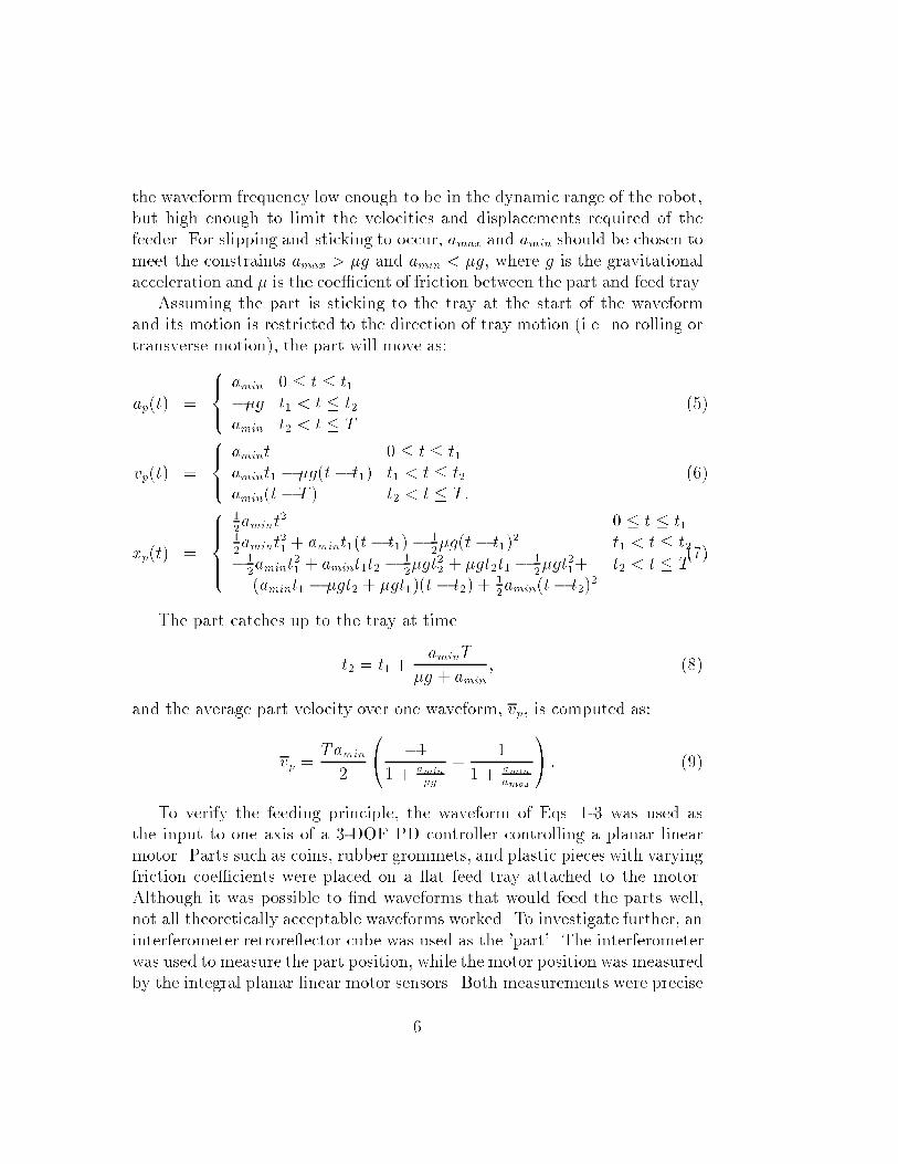
Figure 4: Experimental measurements of feeder and part motion using astick-slip waveform with T = 0:05 s, amin = 1:6 m=s
2, amax = 10:1 m=s
2.
Both the part and feed tray are aluminum; based on the part motion duringthe slip phase, the coe�cient of friction appears to be approximately 0.2.
7
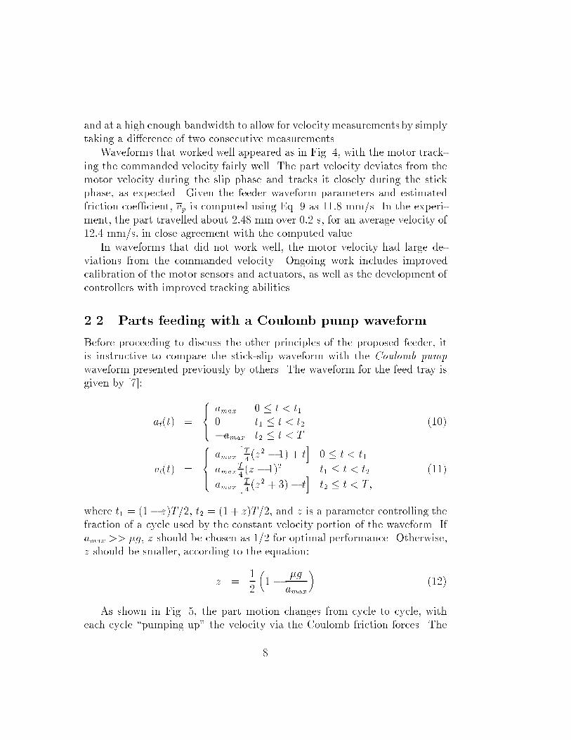
and at a high enough bandwidth to allow for velocitymeasurements by simplytaking a di�erence of two consecutive measurements.
Waveforms that worked well appeared as in Fig. 4, with the motor track-ing the commanded velocity fairly well. The part velocity deviates from themotor velocity during the slip phase and tracks it closely during the stickphase, as expected. Given the feeder waveform parameters and estimatedfriction coe�cient, vp is computed using Eq. 9 as 11:8 mm/s. In the experi-ment, the part travelled about 2:48 mm over 0:2 s, for an average velocity of12:4 mm/s, in close agreement with the computed value.
In waveforms that did not work well, the motor velocity had large de-viations from the commanded velocity. Ongoing work includes improvedcalibration of the motor sensors and actuators, as well as the development ofcontrollers with improved tracking abilities.
2.2 Parts feeding with a Coulomb pump waveform
Before proceeding to discuss the other principles of the proposed feeder, itis instructive to compare the stick-slip waveform with the Coulomb pump
waveform presented previously by others. The waveform for the feed tray isgiven by [7]:
at(t) =
8><>:
amax 0 � t < t10 t1 � t < t2�amax t2 � t < T
(10)
vt(t) =
8>><>>:
amax
hT
4(z2 � 1) + t
i0 � t < t1
amaxT
4(z � 1)2 t1 � t < t2
amax
hT
4(z2 + 3)� t
it2 � t < T;
(11)
where t1 = (1� z)T=2, t2 = (1 + z)T=2, and z is a parameter controlling thefraction of a cycle used by the constant velocity portion of the waveform. Ifamax >> �g, z should be chosen as 1=2 for optimal performance. Otherwise,z should be smaller, according to the equation:
z =1
2
�1 �
�g
amax
�(12)
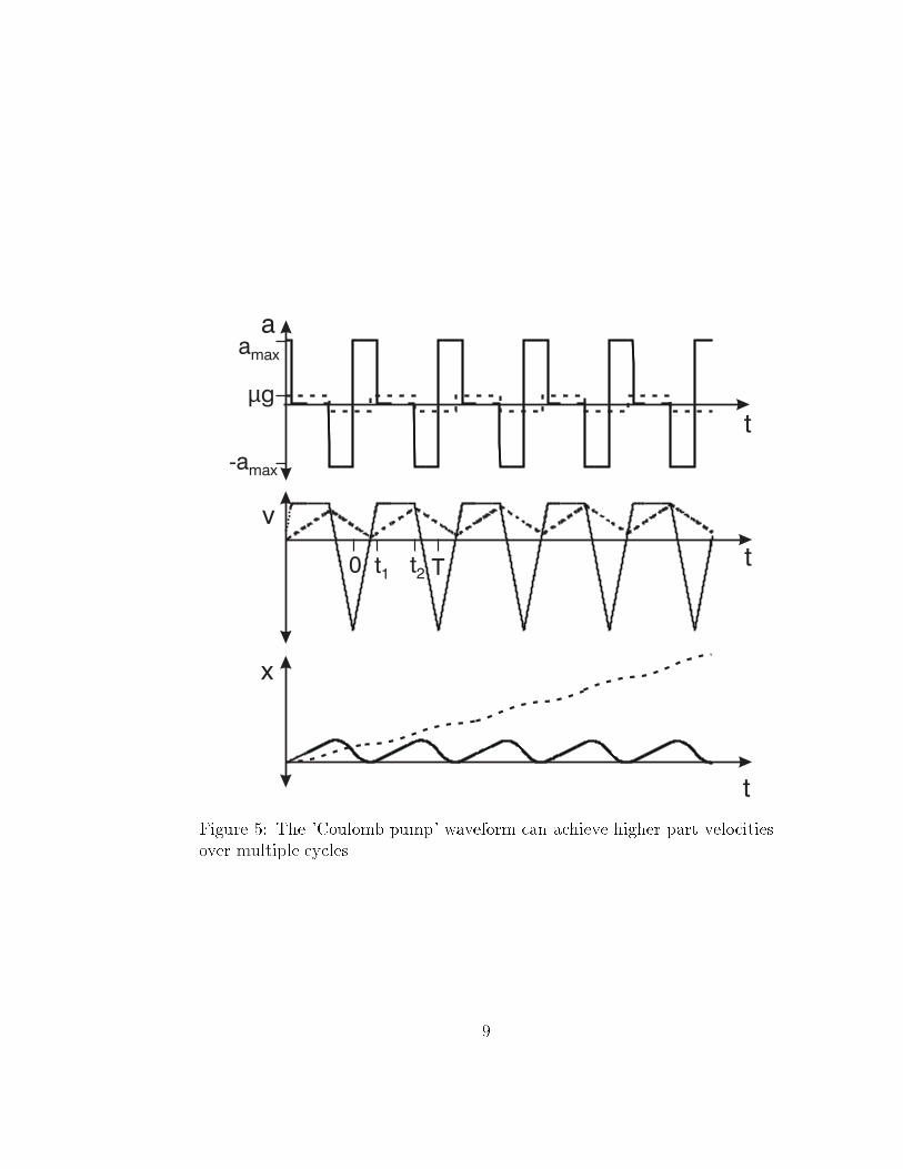
As shown in Fig. 5, the part motion changes from cycle to cycle, witheach cycle \pumping up" the velocity via the Coulomb friction forces. The
8
a
v
x
t
t
t
-amax
µg
t1 t2
amax
0 T
Figure 5: The 'Coulomb pump' waveform can achieve higher part velocitiesover multiple cycles.
9
0 0.02 0.04 0.06 0.08 0.1 0.12 0.14 0.16 0.18 0.2
−100
−50
0
50
100
time [sec]
velo
city
[mm
/s]
motor measured motor commandedpart measured
0 0.02 0.04 0.06 0.08 0.1 0.12 0.14 0.16 0.18 0.2−0.5
0
0.5
1
1.5
2
2.5
3
3.5
4
4.5
5
time [sec]
posi
tion
[mm
]
motor measuredpart measured
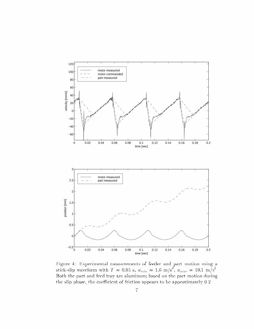
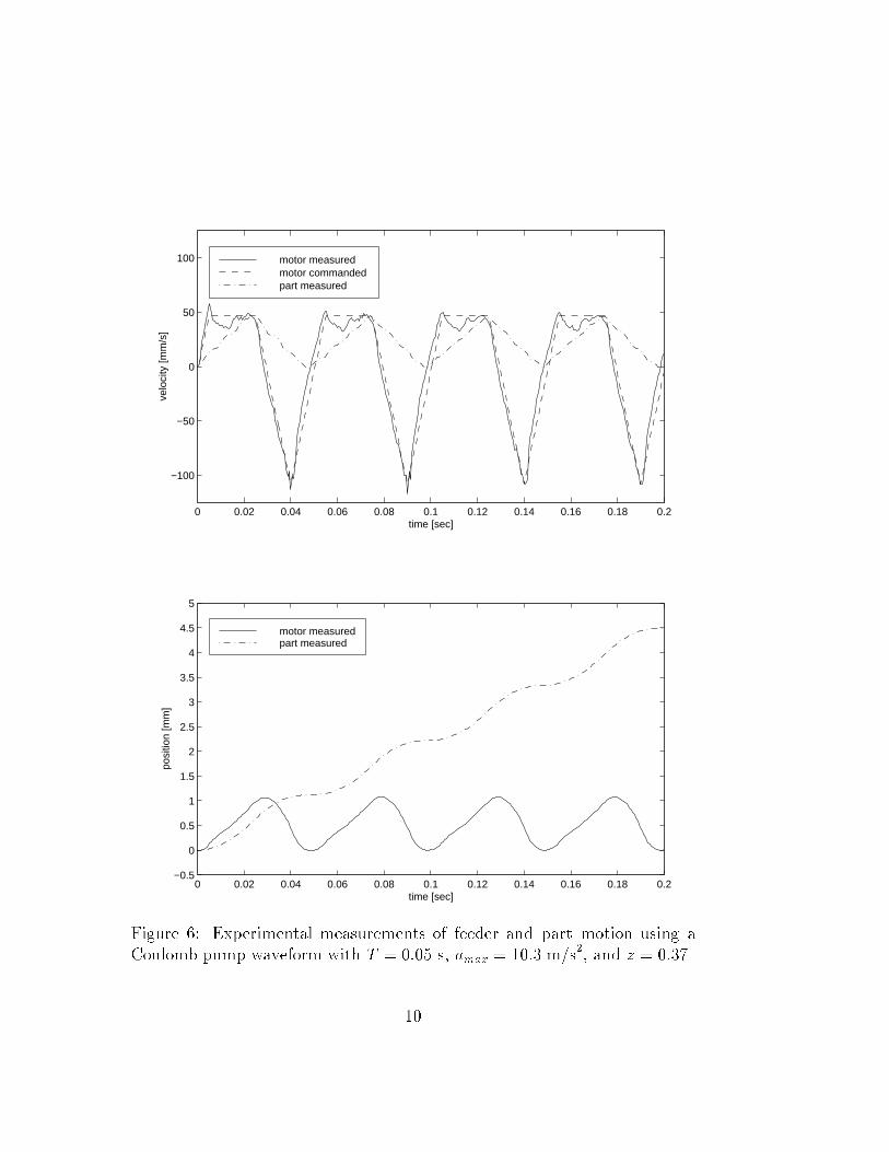
Figure 6: Experimental measurements of feeder and part motion using aCoulomb pump waveform with T = 0:05 s, amax = 10:3 m=s
2, and z = 0:37.
10
part velocity is now best characterized by the equilibrium velocity, which isthe value that the average waveform velocity eventually reaches, given by [7]:
veq = amaxTz2
4: (13)
The Coulomb pump waveform was also implemented on one axis of theplanar linear motor. Once again, the main problem was in �nding a waveformthat the motor followed reasonably well. One example is shown in Fig. 6.Applying Eq. 13, the computed equilibrium velocity is 17:6 mm/s, while theobserved velocity in Fig. 6 is 4:5 mm=0:2 s, or 22:5 mm=s, a fairly closematch.
The examples shown in Fig. 4 and Fig. 6 (which both use similar wave-form frequencies and maximum accelerations and the same part) show thatthe Coulomb pump waveform has a higher part velocity than the stick-slipwaveform, but requires larger velocity and translations from the feeder. Moreimportantly, the larger forward accelerations of this waveform appear to causeproblems for sloped feed trays, which will be shown to be important in thefollowing section.
3 Ramps for singulation
Given the above technique for generating part motions, the problem of singu-lation is now explored. One technique for singulation is to vary the feed rateof the parts based on their position. In particular, if the feed rate increases asthe parts move from one region to another, the parts will tend to spread out.This technique is used in the dual conveyors of the Adept exible feeder [3],schematically shown in the top half of Fig. 7, where one conveyor drops partsonto a faster conveyor. To achieve a similar e�ect for the proposed feeder,a sloped section may be added to the feeder tray. Assuming that parts willclimb up the ramp, but at a slower rate than if they were on a at surface,the parts on the at plateau region at the top of the ramp will be singulatedrelative to the parts on the ramp section, as depicted in the bottom half ofFig. 7. A model for parts on ramps is derived in this section that supportsthis conclusion.
11
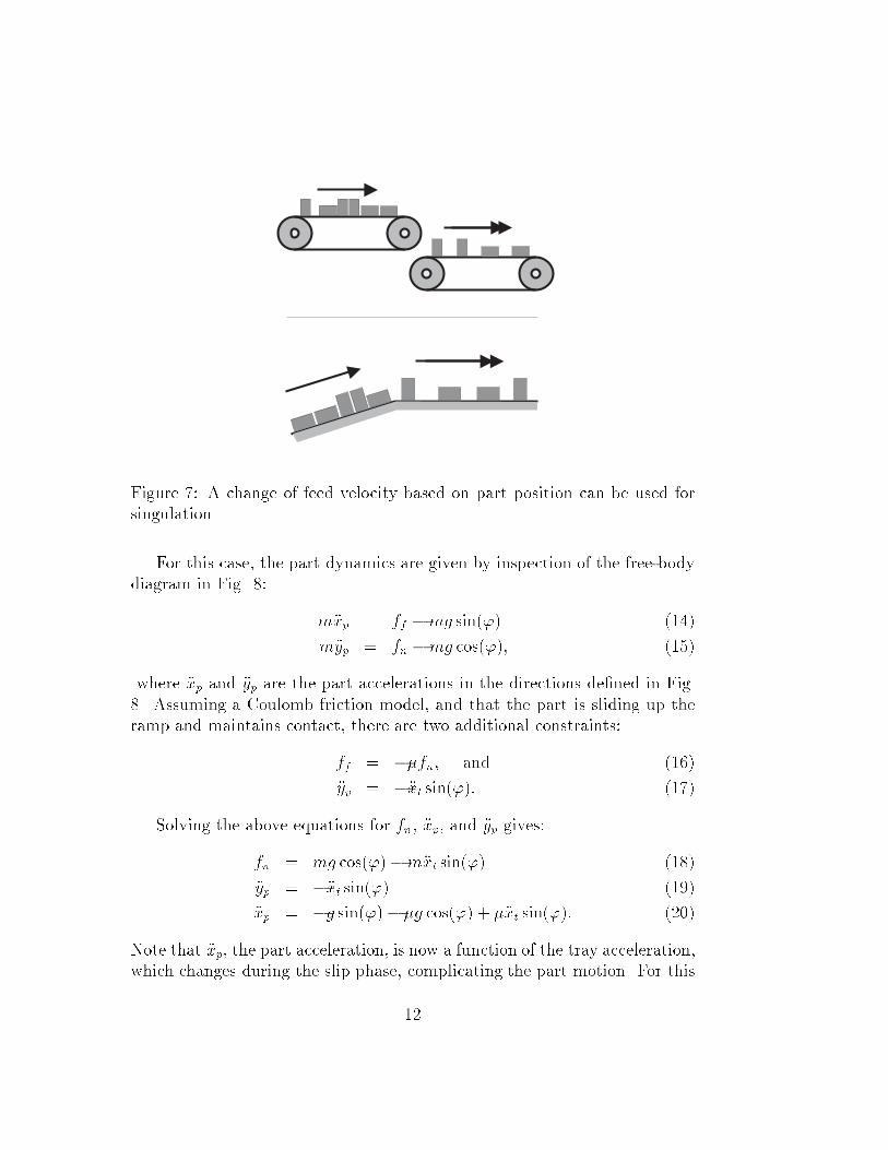
Figure 7: A change of feed velocity based on part position can be used forsingulation.
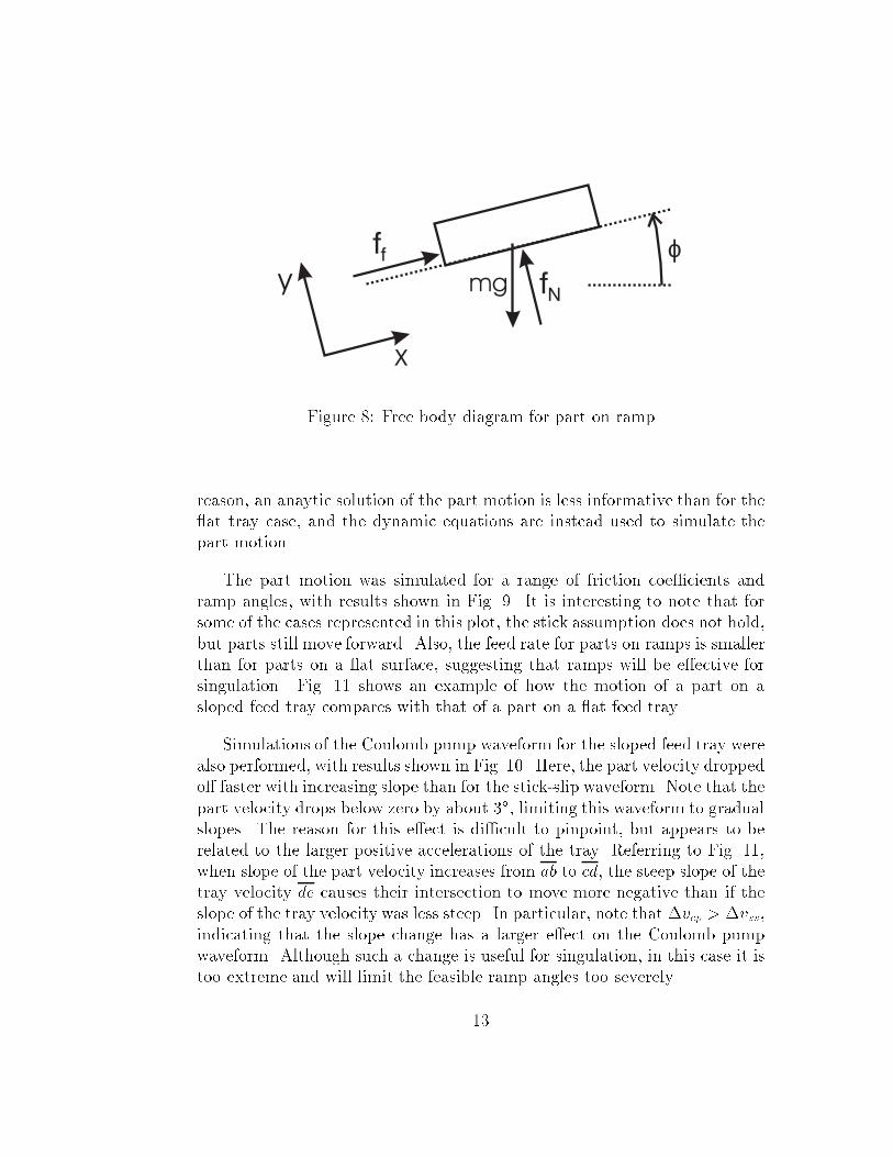
For this case, the part dynamics are given by inspection of the free-bodydiagram in Fig. 8:
m�xp = ff �mg sin(') (14)
m�yp = fn �mg cos('); (15)
where �xp and �yp are the part accelerations in the directions de�ned in Fig.8. Assuming a Coulomb friction model, and that the part is sliding up theramp and maintains contact, there are two additional constraints:
ff = ��fn; and (16)
�yp = ��xt sin('): (17)
Solving the above equations for fn, �xp, and �yp gives:
fn = mg cos(')�m�xt sin(') (18)
�yp = ��xt sin(') (19)
�xp = �g sin(')� �g cos(') + ��xt sin('): (20)
Note that �xp, the part acceleration, is now a function of the tray acceleration,which changes during the slip phase, complicating the part motion. For this
12
y
x
ϕmg fN
ff
Figure 8: Free body diagram for part on ramp
reason, an anaytic solution of the part motion is less informative than for the at tray case, and the dynamic equations are instead used to simulate thepart motion.
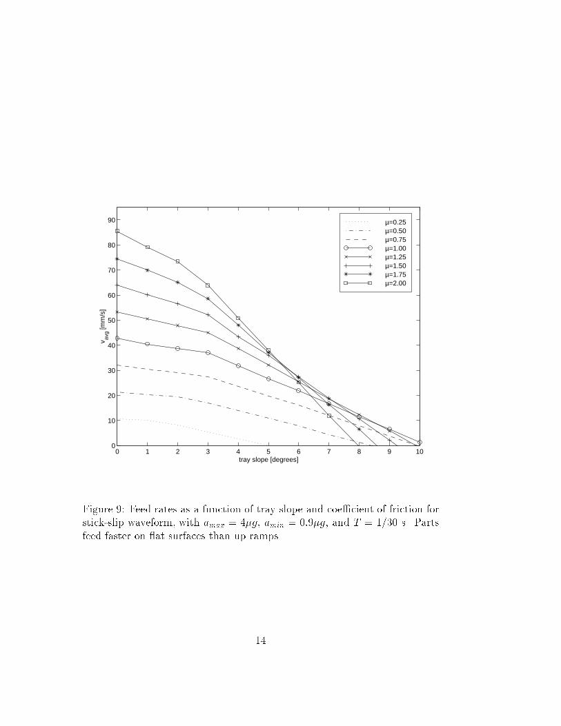
The part motion was simulated for a range of friction coe�cients andramp angles, with results shown in Fig. 9. It is interesting to note that forsome of the cases represented in this plot, the stick assumption does not hold,but parts still move forward. Also, the feed rate for parts on ramps is smallerthan for parts on a at surface, suggesting that ramps will be e�ective forsingulation. Fig. 11 shows an example of how the motion of a part on asloped feed tray compares with that of a part on a at feed tray.
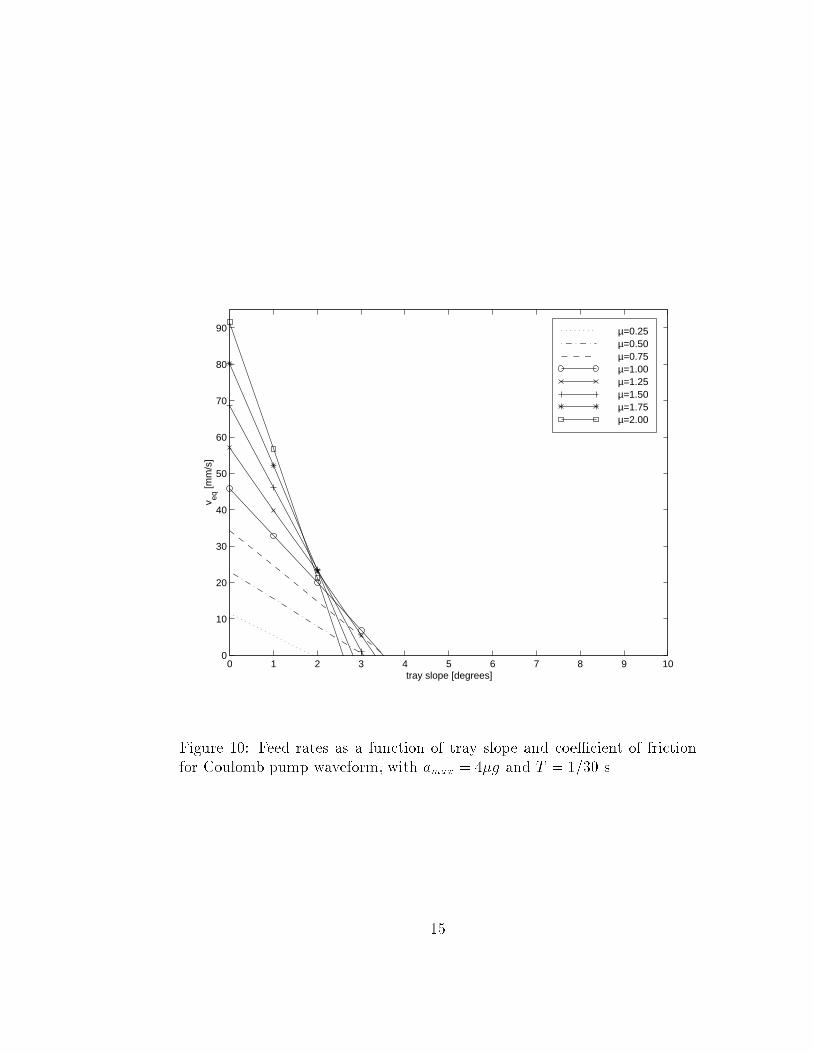
Simulations of the Coulomb pump waveform for the sloped feed tray werealso performed, with results shown in Fig. 10. Here, the part velocity droppedo� faster with increasing slope than for the stick-slip waveform. Note that thepart velocity drops below zero by about 3�, limiting this waveform to gradualslopes. The reason for this e�ect is di�cult to pinpoint, but appears to berelated to the larger positive accelerations of the tray. Referring to Fig. 11,when slope of the part velocity increases from ab to cd, the steep slope of thetray velocity de causes their intersection to move more negative than if theslope of the tray velocity was less steep. In particular, note that �vcp > �vss,indicating that the slope change has a larger e�ect on the Coulomb pumpwaveform. Although such a change is useful for singulation, in this case it istoo extreme and will limit the feasible ramp angles too severely.
13
0 1 2 3 4 5 6 7 8 9 100
10
20
30
40
50
60
70
80
90
tray slope [degrees]
v avg [m
m/s
]
µ=0.25µ=0.50µ=0.75µ=1.00µ=1.25µ=1.50µ=1.75µ=2.00
Figure 9: Feed rates as a function of tray slope and coe�cient of friction forstick-slip waveform, with amax = 4�g, amin = 0:9�g, and T = 1=30 s. Partsfeed faster on at surfaces than up ramps.
14
0 1 2 3 4 5 6 7 8 9 100
10
20
30
40
50
60
70
80
90
tray slope [degrees]
v eq [m
m/s
]
µ=0.25µ=0.50µ=0.75µ=1.00µ=1.25µ=1.50µ=1.75µ=2.00
Figure 10: Feed rates as a function of tray slope and coe�cient of frictionfor Coulomb pump waveform, with amax = 4�g and T = 1=30 s.
15
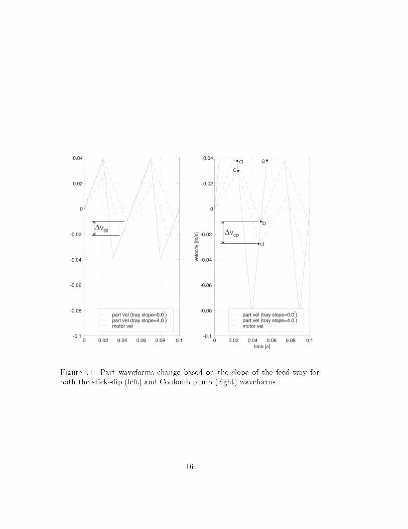
Figure 11: Part waveforms change based on the slope of the feed tray forboth the stick-slip (left) and Coulomb pump (right) waveforms.
16
4 A miniature mobile parts feeder
Given the ability to produce part motions using the waveforms discussedabove, how can this capability be used for singulating and reorienting bulkparts?
First, if the feed tray (rigidly attached to the planar linear motor) pro-vides a loop feed-path for the parts, the type of recirculation path found insuccessful commercial parts feeders can be duplicated very compactly withinthe feed tray. The particular loop chosen is that of an annulus, so that a sin-gle rotational vibration waveform of the feeder will su�ce to keep the parts owing around the loop.
Parts must be singulated both radially and along the circumferential feedpath. Along the direction of feeding, a ramp is used to provide singulation,as discussed in the previous section. Two e�ects were expected to providesingulation radially across the feed path. First, the parts were expected tomove locally along tangents, which would tend to make them collect towardsthe outer wall of the feed tray. In addition, the ramp section does not havea constant slope, but gets steeper with decreasing radius. If the waveformis selected carefully, it could be possible to cause parts to slide back downthe ramp for small radii, but still climb at larger radii. This technique wouldallow for a programmable size feeding region at the outer wall of the feedtray. Simulation results below examine these e�ects.
Once singulated and in the plateau region, an overhead vision system canbe used to detect parts in the correct orientation, similar to the Adept exiblefeeder. The feeder can then move2 to deliver the parts to any overhead devicewithin its large workspace, limited only by the size of the platens and lengthof the tether.
Incorrectly oriented parts rejected by the vision system continue aroundthe feed path and pass over the dropo� (a nice side-e�ect of the ramp section),which allows for a reorientation. This e�ect allows for reorienting parts outof the plane, despite a feeder that is restricted to planar motions. Dependingon the part materials, part geometry, and dropo� height, the part mightalways just ip over or might assume a more random orientation change.This aspect of the feeder is not investigated further in this work.
At this point, the proposed feeder bears a resemblance to a vibratory
2Of course, it must move with small enough accelerations that the parts don't slide
relative to the feed tray.
17
ϕmg
ff1
fN
ff2
i
k
jB
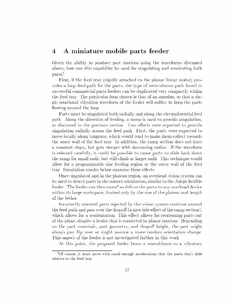
Figure 12: Local free body diagram for a part on an annular tray. (� denotesa vector pointing out of the page.)
bowl feeder, so it is important to note the di�erences. First, mobility with-out additional actuators allows the feeder to service multiple assembly robotsand feed parts very close to the assembly location. Most bowl feeders lack exibility and are designed for a speci�c part, while the proposed feeder trayhas very few physical parameters (the height of the dropo�, the outside di-ameter, and the proportion of the circle allocated for the ramp section), noneof which are tightly coupled to the part geometry. Finally, bowl feeders nor-mally have large masses and limited vibration adjustments. The proposedfeeder uses small closed-loop planar linear motor actuators that can be pre-cisely controlled to give just the needed accelerations, reducing audible andmechanical vibrations. Vibratory feeder bowls do have the advantage of highfeed rates and little need for sensing, but for many applications these featuresare outweighed by the problems noted above.
4.1 Dynamic model
In this section, a dynamic model is derived for a part on the feed tray dis-cussed above. The part is assumed to be a point mass that stays in contactwith the feed tray, and a Coulomb friction model is assumed.
The free-body diagram for the part is shown in Fig. 12. Coordinatesystems used in the derivation are de�ned as in Fig. 13. Note that coordinateframe A is �xed, and coordinate frame B is aligned with the part at this
particular instant in time but is also �xed. The dynamics problem is todetermine the acceleration of the part along the tray given the part positionand velocity, and tray position, velocity, and acceleration. The dynamics ofboth a sticking case and slipping case must be considered.
18
k
j
iA
ik
j
B
rθ +θt
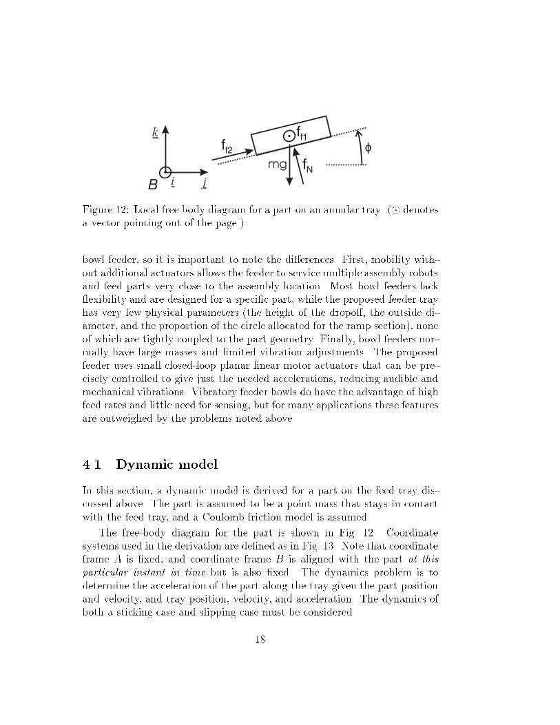
Figure 13: Coordinate frame and angle direction de�nitions for dynamicequations. A is �xed for all time, while B is de�ned only for an instant intime at the part location.
By inspection of the free-body diagram, the part dynamics are given by:
�x = ff1=m (21)
�y = ff2 cos(')=m� fNsin(')=m (22)
�z = ff2 sin(')=m+ fNcos(')=m� g; (23)
where ff1;2, fN , g, and ' are de�ned in Fig. 12, with x; y; and z are de�nedrelative to frame B.
For the slipping case, Coulomb's law gives:
ff =
264
ff1ff2 cos(')ff2 sin(')
375 = �fN
vp � vt
kvp � vtk; (24)
where vp is the part velocity, and vt is the local tray velocity, both expressedin coordinate frame B.
19
An additional equation is given by the constraint that the part stays onthe surface of the feed tray:
z =h
�(�(�x; �y)� �t);where (25)
�(�x; �y) = arctan(�y=�x); (26)
h is the total change in height of the ramp,3 and �t is the rotation angle ofthe tray. Here, �x and �y are de�ned relative to frame A. Di�erentiating Eq.26 twice, substituting polar coordinates for the position and velocity terms,mapping the acceleration vector from frame A to frame B, and simplifyinggives:
�� =�y
r�
2 _r _�
r: (27)
Substituting this equation into the second derivative of Eq. 25 gives:
�z =h
�(�y
r�
2 _r _�
r� ��t): (28)
Note that the local slope of the ramp ' shown in Fig. 12, is related to h by:
tan(') =h
�r: (29)
This equation is used to simplify Eq. 28 to:
�z = tan(')(�y � 2 _r _� � r��t): (30)
To solve for fN , Eqs. 22 and 23 are substituted into Eq. 30, giving aftersimpli�cation:
fN = mg cos(')� 2m sin(') _r _� �m��t sin('): (31)
This result for fN can then be substituted into Eq. 24 to get ff1;2, and intoEqs. 21-23 to compute the part acceleration for the slipping case. Becausecoordinate frame B is only valid at an instant in time, the acceleration vectormust be transformed to a coordinate frame �xed to the workspace beforeintegration.
3If the part is on the plateau, h is set to zero.
20
For the sticking case, the part is �xed relative to the feed tray, and thepart accelerations are given based on the tray motion and part position:
�x = �r _�2t (32)
�y = r��t (33)
�z = 0; (34)
To check whether the friction forces are su�cient to keep the part stuck tothe feed tray, these acceleration values are substituted into Eqs. 21-23, whichcan be solved for fN and ff1;2:
fN = �mr��t sin(') +mg cos(') (35)
ff1 = �mr _�2t (36)
ff2 = mr��t cos(')�mg sin(') (37)
Both the sticking and sliding equations are evaluated every simulationiteration. The sticking mode results are used if k[ff1 ff2]Tk < �fN (whichindicates that the friction forces are su�cient to maintain sticking), and therelative velocity kvp � vtk is below some threshold. Otherwise, the slidingmode results are used. For both cases, the sign of fN is checked to be surethe part does not leave the tray surface.
4.2 Simulation results
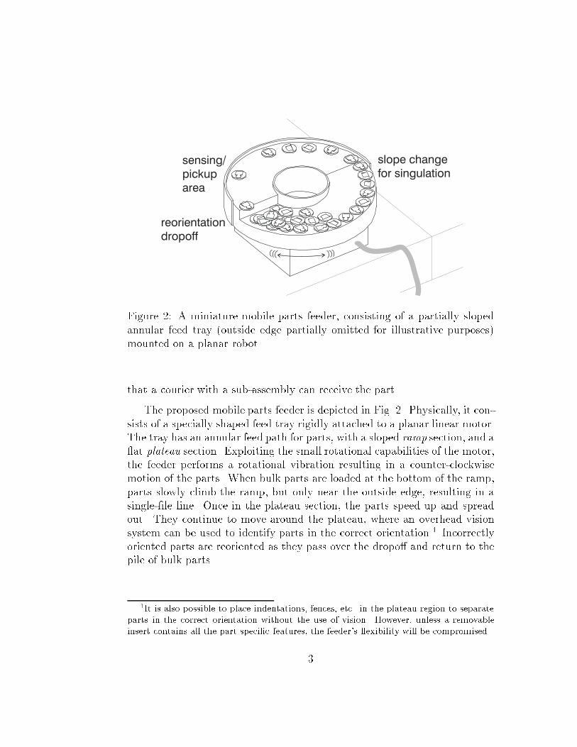
Simulations were performed for a feeder with an outer radius of 9 cm, an innerradius of 3 cm, and a 180� ramp with a total height change of 2 cm. The partmass was chosen as 20 g, with a coe�cient of friction between the part andtray of � = 0:2. The tray was set to follow a rotational stick-slip waveform,with parameters T = 1=30 s, amin = 9:0�g rad=s2, and amax = 66:7�g rad=s2.The initial position of the part was set to a polar array of positions on thetray, with zero initial velocity. For each starting position, the part motionwas simulated for 5 s, and the sequence of part positions was recorded.
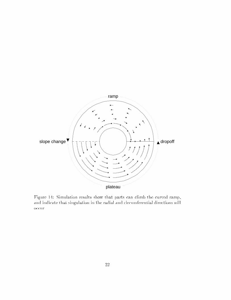
Results for each part starting position are shown in Fig. 14. Note thatparts only feed up the ramp if they are close to the outer radius of the feeder,which should cause the parts to form a single-�le line, singulating them inthe radial direction. The part velocity on the plateau section is much fasterthan that on the ramp, suggesting that singulation along the direction ofmotion will also work well. It is surprising that the parts move along nearly
21
ramp
plateau
dropoffslope change
Figure 14: Simulation results show that parts can climb the curved ramp,and indicate that singulation in the radial and circumferential directions willoccur.
22
0 0.5 1 1.5 2
−15
−10
−5
0
5
10
time
velo
city
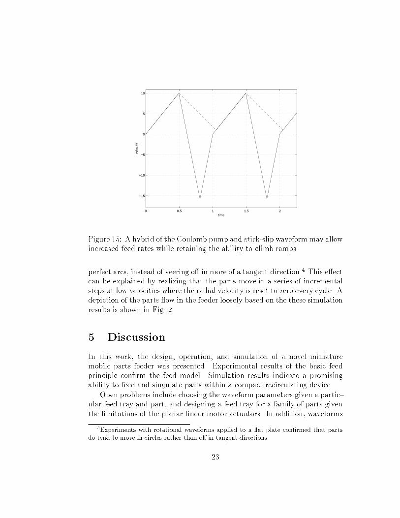
Figure 15: A hybrid of the Coulomb pump and stick-slip waveform may allowincreased feed rates while retaining the ability to climb ramps.
perfect arcs, instead of veering o� in more of a tangent direction.4 This e�ectcan be explained by realizing that the parts move in a series of incrementalsteps at low velocities where the radial velocity is reset to zero every cycle. Adepiction of the parts ow in the feeder loosely based on the these simulationresults is shown in Fig. 2.
5 Discussion
In this work, the design, operation, and simulation of a novel miniaturemobile parts feeder was presented. Experimental results of the basic feedprinciple con�rm the feed model. Simulation results indicate a promisingability to feed and singulate parts within a compact recirculating device.
Open problems include choosing the waveform parameters given a partic-ular feed tray and part, and designing a feed tray for a family of parts giventhe limitations of the planar linear motor actuators. In addition, waveforms
4Experiments with rotational waveforms applied to a at plate con�rmed that parts
do tend to move in circles rather than o� in tangent directions.
23
other than the stick-slip or Coulomb pump can be considered. Hybrid wave-forms, such as the one shown in Fig. 15 that combine their advantages, orthe formulation of an optimal waveform would improve performance.
There are a number of potential limitations of this feeder. Parts must bestable enough in their pickup orientation to survive the trip up the ramp andthe vibrations without falling over. Parts that tend to nest will probably notbe singulated properly. Parts may become stuck on the transition betweenthe ramp and plateau, even if it is rounded. It might not be possible for thefeeder to move from one overhead device to another smoothly enough thatunwanted part motion does not occur. Feed rates may be too slow to beuseful in a real automated assembly system. However, the results to date areencouraging enough that the author intends to build a prototype parts feederof this type. Fabrication techniques for the feed tray are being considered,and improved calibration and control of the planar linear motor to allow formore precise tracking of the commanded waveforms is being investigated.
Acknowledgements
The author wishes to thank Matt Mason for helpful discussions and espe-cially for suggesting the use of ramps for singulation purposes, and RalphHollis and other MSL members for encouragement and support. This workis supported in part by NSF grants DMI-9523156 and CDA-9503992. Theauthor is supported by an AT&T Foundation Fellowship.
24
References
[1] Z. J. Butler, A. A. Rizzi, and R. L. Hollis, \Integrated precision 3-DOFposition sensor for planar linear motors," in Proc. IEEE Int'l Conf. on
Robotics and Automation, 1998.
[2] A. E. Quaid and R. L. Hollis, \3-DOF closed-loop control for planarlinear motors," in Proc. IEEE Int'l Conf. on Robotics and Automation,May 1998.
[3] D. Gudmundsson and K. Goldberg, \Tuning robotic part feeder parame-ters to maximize throughput," in Proc. IEEE Int'l Conf. on Robotics and
Automation, pp. 2440{2445, April 1997.
[4] J. Krishnaswamy, M. J. Jakiela, and D. E. Whitney, \Mechanics ofvibration-assisted entrapment with application to design," in Proc. IEEE
Int'l Conf. on Robotics and Automation, pp. 838{845, April 1996.
[5] J. Hollingum, \Sweeping it over the carpet," Assembly Automation,vol. 15, no. 3, pp. 29{30, 1995.
[6] K.-F. B�ohringer, V. Bhatt, and K. Y. Goldberg, \Sensorless manipulationusing transverse vibrations of a plate," in Proc. IEEE Int'l Conf. on
Robotics and Automation, pp. 1989{1996, May 1995.
[7] D. Reznik and J. Canny, \The Coulomb pump: a novel parts feedingmethod using a horizontally-vibrating surface," in Proc. Int'l Conf. on
Intelligent Robots and Systems, pp. 869{874, 1998.
[8] D. Reznik and J. Canny, \A at rigid plate is a universal planar manipu-lator," in Proc. Int'l Conf. on Intelligent Robots and Systems, pp. 1471{1477, 1998.
[9] A. A. Rizzi, J. Gowdy, and R. L. Hollis, \Agile assembly architecture: anagent based approach to modular precision assembly systems," in Proc.
IEEE Int'l Conf. on Robotics and Automation, pp. 1511{1516, April 1997.
25