Embed Size (px)
Citation preview
MASKANA, I+D+ingeniería 2014
IEE 175
Quadcopter stabilization by using PID controllers
Luis E. Romero1, David F. Pozo
2, Jorge A. Rosales
3
1 Escuela Politécnica Nacional, Ladrón de Guevara E11 - 253, Quito, Ecuador, EC170127.
2 IEEE Member, Universidad de Las Américas, Av. De los Granados E12-41 y Colimes esq., Quito,
Ecuador, EC170125. 3
IEEE Member, Escuela Politécnica Nacional, Ladrón de Guevara E11 - 253, Quito, Ecuador,
EC170127.
Autores para correspondencia: [email protected], [email protected],
Fecha de recepción: 21 de septiembre de 2014 - Fecha de aceptación: 17 de octubre de 2014
RESUMEN
En este trabajo se presenta la estabilización de un cuadricóptero mediante el uso de controladores PID
para la regulación de sus 4 movimientos básicos: ángulos de alabeo, cabeceo, guiñada y altitud. La
estabilización del sistema se realiza a partir de un modelo simplificado que facilita la implementación
de controladores en un sistema SISO, demostrando efectividad dentro de un rango de ±10° para los
ángulos de alabeo y cabeceo y rango completo en guiñada y altitud. El módulo del controlador PID es
diseñado para ser usado en cuadricópteros comerciales y ha sido implementado en base a sensores
inerciales y ultrasónicos. Además, el sistema cuenta con una interface para observar el desempeño de
la aeronave durante el vuelo.
Palabras clave: Cuadricóptero, sistemas de control, controladores PID, UAV.
ABSTRACT
This work presents the stabilization of a quadcopter by using PID controllers to regulate its four basic
movements: roll, pitch, yaw angles, and altitude. The stabilization of the system is made from a
simplified model which makes easier the implementation of controllers on a SISO system, showing
effectiveness within a range of ±10° for a roll and pitch angles and a full range on yaw angle and
altitude. The PID controller module is designed to be used with commercial quadcopters and it has
been implemented using inertial and ultrasonic sensors. Furthermore, the system also features a
wireless interface to observe the aircraft performance during the flight.
Keywords: Quadcopter, control systems, PID controllers, UAV.
1. INTRODUCTION
The development and investigation of autonomous flight systems have increased lately because of the
increasing amount of applications of unmanned aerial vehicle (UAV) in military fields such as
intelligence, surveillance, and reconnaissance missions, and in civil fields like aerial surveillance,
aerial photography and video, firefighting, and many others that are emerging (Natraj et al., 2013;
Nex & Remondino, 2014). In all cases, the incentive for the investigation in this field is the necessity
to replace human intervention on high-risk jobs or missions.
In modern times, there is a wide variety of aircrafts used for UAVs, like fixed-wing airplanes,
airships, and helicopters, among others (Benavidez et al., 2014).Nevertheless, the platforms that have
caught a lot of attention for investigation projects are multirotor helicopters, in particular quadrotors,
MASKANA, I+D+ingeniería 2014
IEE 176
because these aircrafts have a lot of advantages with respect to other aircrafts. Quadcopters have a
simple structure and a great flight capacity and maneuverability, such as vertical take-off and landing
and hovering flight (Escamilla, 2010).
A quadcopter has four rotors, each one of which has independent speed, allowing a balanced
variation of the rotors' speed and thus generating the thrust and accelerations in the desired directions.
Quadcopters are six-degrees-of-freedom (DoF) systems, what means that they can move along the
three space axes X, Y and Z, and turn on the aircraft’s body axes describing roll (φ), pitch (θ) and yaw
(ψ) angles. However, in the aircraft, there is only direct control over four DoF, corresponding to the
altitude and the three angles: roll, pitch and yaw. Roll and pitch movements also generate motion
along the Y and X axes of space, respectively.
Despite the advantages of quadcopters, like other aircrafts, they are extremely unstable systems,
and so any imbalance in their motion (especially in roll and pitch) generates angular and linear
accelerations, which can cause a collision if not compensated for quickly. Moreover, the quadcopter
system is nonlinear and the movements are coupled with each other. PID controllers offer a simple but
effective solution to stabilize the aircraft because they make it possible to treat every variable
independently within a limited range in which the behavior of the quadcopter is approximately linear
(Bouabdallah et al., 2005; Castillo et al., 2005).
This work presents the development of a quadcopter’s model considering its dynamic behavior,
after which, based on an analysis of its involved variables a simplification is made, which makes
easier the implementation of PID controllers on a SISO system.
2. MODELLING
PID controller design requires prior modeling of the system to know its behavior. Quadrotors have
their four propellers placed on the ends of a cross-like structure. To maintain the balance of the
overall torque, one pair of rotors spins in a clockwise direction while the remaining pair spins in a
counter-clockwise direction. The speed of every rotor is controlled independently to generate the
thrust and torque to move the aircraft. According to the orientation of the motion, there is an “x”
mode and a “+” mode (see Fig. 1).
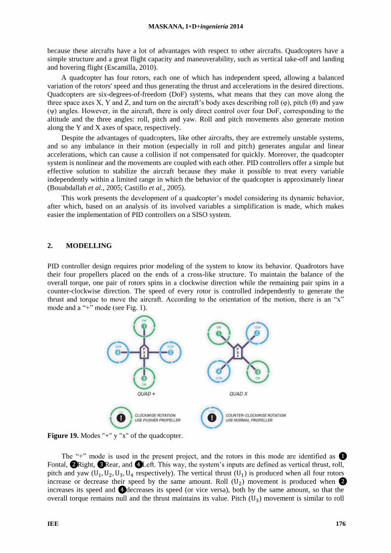
Figure 19. Modes "+" y "x" of the quadcopter.
The “+” mode is used in the present project, and the rotors in this mode are identified as ❶
Fontal, ❷ Right, ❸ Rear, and ❹ Left. This way, the system’s inputs are defined as vertical thrust, roll, pitch and yaw ( respectively). The vertical thrust ( ) is produced when all four rotors
increase or decrease their speed by the same amount. Roll ( ) movement is produced when ❷
increases its speed and ❹ decreases its speed (or vice versa), both by the same amount, so that the
overall torque remains null and the thrust maintains its value. Pitch ( ) movement is similar to roll
MASKANA, I+D+ingeniería 2014
IEE 177
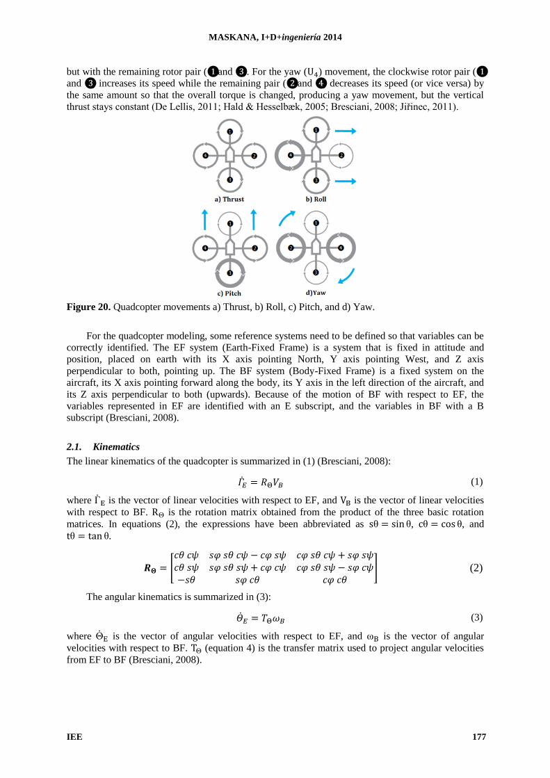
but with the remaining rotor pair (❶ and ❸). For the yaw ( ) movement, the clockwise rotor pair (❶
and ❸) increases its speed while the remaining pair (❷ and ❹) decreases its speed (or vice versa) by
the same amount so that the overall torque is changed, producing a yaw movement, but the vertical
thrust stays constant (De Lellis, 2011; Hald & Hesselbæk, 2005; Bresciani, 2008; Jiřinec, 2011).
Figure 20. Quadcopter movements a) Thrust, b) Roll, c) Pitch, and d) Yaw.
For the quadcopter modeling, some reference systems need to be defined so that variables can be
correctly identified. The EF system (Earth-Fixed Frame) is a system that is fixed in attitude and
position, placed on earth with its X axis pointing North, Y axis pointing West, and Z axis
perpendicular to both, pointing up. The BF system (Body-Fixed Frame) is a fixed system on the
aircraft, its X axis pointing forward along the body, its Y axis in the left direction of the aircraft, and
its Z axis perpendicular to both (upwards). Because of the motion of BF with respect to EF, the
variables represented in EF are identified with an E subscript, and the variables in BF with a B
subscript (Bresciani, 2008).
2.1. Kinematics
The linear kinematics of the quadcopter is summarized in (1) (Bresciani, 2008):
(1)
where is the vector of linear velocities with respect to EF, and is the vector of linear velocities
with respect to BF. is the rotation matrix obtained from the product of the three basic rotation
matrices. In equations (2), the expressions have been abbreviated as θ θ, θ θ, and
θ θ.
𝑐 𝑐 𝑐 𝑐 𝑐 𝑐 𝑐 𝑐 𝑐 𝑐 𝑐 𝑐 𝑐 𝑐
(2)
The angular kinematics is summarized in (3):
(3)
where is the vector of angular velocities with respect to EF, and is the vector of angular
velocities with respect to BF. (equation 4) is the transfer matrix used to project angular velocities
from EF to BF (Bresciani, 2008).
MASKANA, I+D+ingeniería 2014
IEE 178
𝑐 𝑐
𝑐
𝑐
𝑐
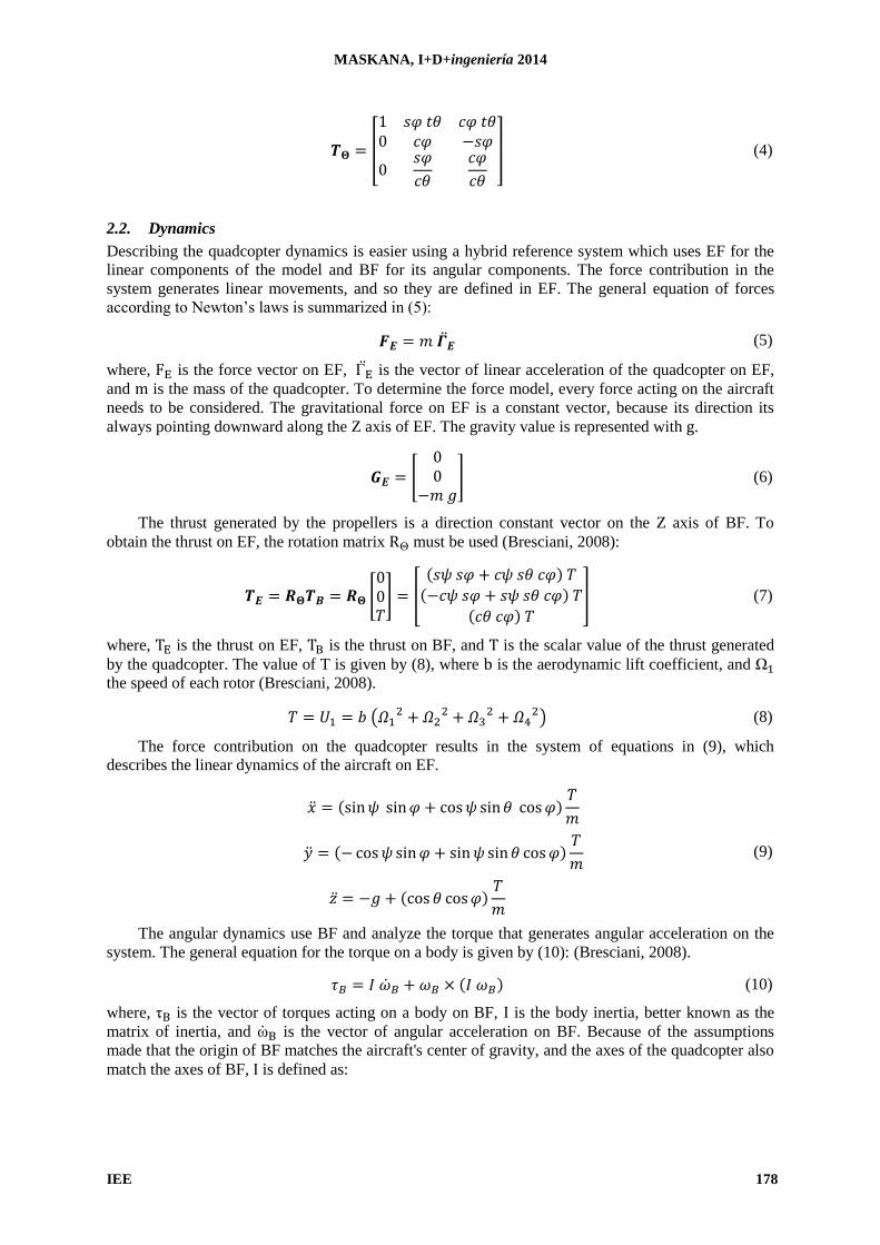
(4)
2.2. Dynamics
Describing the quadcopter dynamics is easier using a hybrid reference system which uses EF for the
linear components of the model and BF for its angular components. The force contribution in the
system generates linear movements, and so they are defined in EF. The general equation of forces
according to Newton’s laws is summarized in (5):
(5)
where, is the force vector on EF, is the vector of linear acceleration of the quadcopter on EF,
and is the mass of the quadcopter. To determine the force model, every force acting on the aircraft
needs to be considered. The gravitational force on EF is a constant vector, because its direction its
always pointing downward along the Z axis of EF. The gravity value is represented with .
(6)
The thrust generated by the propellers is a direction constant vector on the Z axis of BF. To
obtain the thrust on EF, the rotation matrix must be used (Bresciani, 2008):
𝑐 𝑐 𝑐 𝑐
𝑐 𝑐 (7)
where, is the thrust on EF, is the thrust on BF, and is the scalar value of the thrust generated
by the quadcopter. The value of T is given by (8), where is the aerodynamic lift coefficient, and Ω
the speed of each rotor (Bresciani, 2008).
(8)
The force contribution on the quadcopter results in the system of equations in (9), which
describes the linear dynamics of the aircraft on EF.
(9)
The angular dynamics use BF and analyze the torque that generates angular acceleration on the
system. The general equation for the torque on a body is given by (10): (Bresciani, 2008).
(10)
where, is the vector of torques acting on a body on BF, is the body inertia, better known as the
matrix of inertia, and is the vector of angular acceleration on BF. Because of the assumptions
made that the origin of BF matches the aircraft's center of gravity, and the axes of the quadcopter also
match the axes of BF, is defined as:
MASKANA, I+D+ingeniería 2014
IEE 179
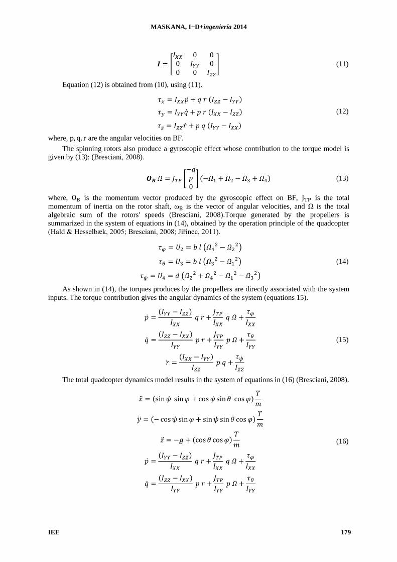
(11)
Equation (12) is obtained from (10), using (11).
(12)
where, are the angular velocities on BF.
The spinning rotors also produce a gyroscopic effect whose contribution to the torque model is
given by (13): (Bresciani, 2008).
(13)
where, is the momentum vector produced by the gyroscopic effect on BF, is the total
momentum of inertia on the rotor shaft, is the vector of angular velocities, and Ω is the total
algebraic sum of the rotors' speeds (Bresciani, 2008).Torque generated by the propellers is
summarized in the system of equations in (14), obtained by the operation principle of the quadcopter
(Hald & Hesselbæk, 2005; Bresciani, 2008; Jiřinec, 2011).
(14)
As shown in (14), the torques produces by the propellers are directly associated with the system
inputs. The torque contribution gives the angular dynamics of the system (equations 15).
(15)
The total quadcopter dynamics model results in the system of equations in (16) (Bresciani, 2008).
(16)
MASKANA, I+D+ingeniería 2014
IEE 180
In the model shown above, the dynamic model of the DC motors has been disregarded because it
is much faster than the quadcopter dynamics.PID controllers are only suitable for linear systems, so
the model must be linearized around an operating point, which is hover flight. Using small-angle
approximations and disregarding the equations of the X and Y movements that are not used in the
control, the system of equations of (17) is obtained (Bresciani, 2008).
(17)
The original model and the linear model have similar behavior for small-angle inputs because the
coupling between variables becomes insignificant. The system shows practically double integrator
behavior, the response of which is a parabolic tendency even for small step inputs.
3. PID CONTROLLER DESIGN
3.1. Architecture
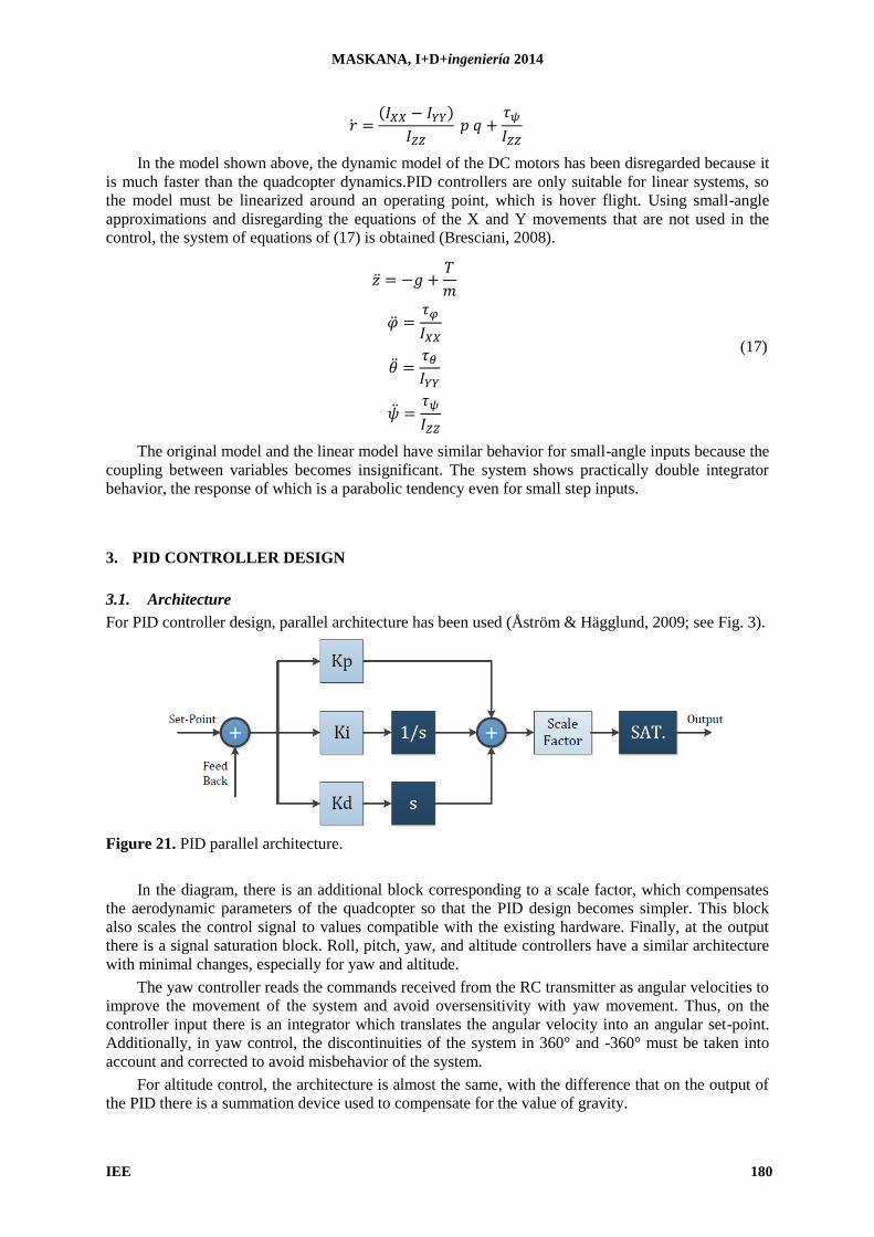
For PID controller design, parallel architecture has been used (Åström & Hägglund, 2009; see Fig. 3).
Figure 21. PID parallel architecture.
In the diagram, there is an additional block corresponding to a scale factor, which compensates
the aerodynamic parameters of the quadcopter so that the PID design becomes simpler. This block
also scales the control signal to values compatible with the existing hardware. Finally, at the output
there is a signal saturation block. Roll, pitch, yaw, and altitude controllers have a similar architecture
with minimal changes, especially for yaw and altitude.
The yaw controller reads the commands received from the RC transmitter as angular velocities to
improve the movement of the system and avoid oversensitivity with yaw movement. Thus, on the
controller input there is an integrator which translates the angular velocity into an angular set-point.
Additionally, in yaw control, the discontinuities of the system in 360° and -360° must be taken into
account and corrected to avoid misbehavior of the system.
For altitude control, the architecture is almost the same, with the difference that on the output of
the PID there is a summation device used to compensate for the value of gravity.
MASKANA, I+D+ingeniería 2014
IEE 181
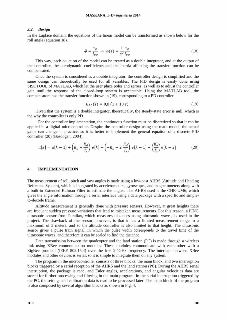
3.2. Design
In the Laplace domain, the equations of the linear model can be transformed as shown below for the
roll angle (equation 18).
(18)
This way, each equation of the model can be treated as a double integrator, and at the output of
the controller, the aerodynamic coefficients and the inertia affecting the transfer function can be
compensated.
Once the system is considered as a double integrator, the controller design is simplified and the
same design can theoretically be used for all variables. The PID design is easily done using
SISOTOOL of MATLAB, which let the user place poles and zeroes, as well as to adjust the controller
gain until the response of the closed-loop system is acceptable. Using the MATLAB tool, the
compensators had the transfer function shown in (19), corresponding to a PD controller.
(19)
Given that the system is a double integrator, theoretically, the steady-state error is null, which is
the why the controller is only PD.
For the controller implementation, the continuous function must be discretized so that it can be
applied in a digital microcontroller. Despite the controller design using the math model, the actual
gains can change in practice, so it is better to implement the general equation of a discrete PID
controller (20) (Basdogan, 2004).
(20)
4. IMPLEMENTATION
The measurement of roll, pitch and yaw angles is made using a low-cost AHRS (Attitude and Heading
Reference System), which is integrated by accelerometers, gyroscopes, and magnetometers along with
a built-in Extended Kalman Filter to estimate the angles. The AHRS used is the CHR-UM6, which
gives the angle information through a serial interface using a data package with a specific and simple-
to-decode frame.
Altitude measurement is generally done with pressure sensors. However, at great heights there
are frequent sudden pressure variations that lead to mistaken measurements. For this reason, a PING
ultrasonic sensor from Parallax, which measures distances using ultrasonic waves, is used in the
project. The drawback of the sensor, however, is that it has a limited measurement range to a
maximum of 3 meters, and so the altitude controller is also limited to that height. The ultrasonic
sensor gives a pulse train signal, in which the pulse width corresponds to the travel time of the
ultrasonic waves, and therefore it can be scaled to find the distance.
Data transmission between the quadcopter and the land station (PC) is made through a wireless
link using XBee communication modules. These modules communicate with each other with a
ZigBee protocol (IEEE 802.15.4) over the free 2.4GHz frequency. The interface between XBee
modules and other devices is serial, so it is simple to integrate them on any system.
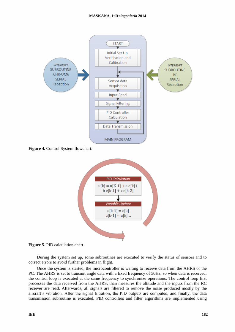
The program in the microcontroller consists of three blocks: the main block, and two interruption
blocks triggered by a serial reception of the AHRS and the land station (PC). During the AHRS serial
interruption, the package is read, and Euler angles, accelerations, and angular velocities data are
stored for further processing and filtering in the main program. In the serial interruption triggered by
the PC, the settings and calibration data is read to be processed later. The main block of the program
is also composed by several algorithm blocks as shown in Fig. 4.
MASKANA, I+D+ingeniería 2014
IEE 182
Figure 4. Control System flowchart.
Figure 5. PID calculation chart.
During the system set up, some subroutines are executed to verify the status of sensors and to
correct errors to avoid further problems in flight.
Once the system is started, the microcontroller is waiting to receive data from the AHRS or the
PC. The AHRS is set to transmit angle data with a fixed frequency of 50Hz, so when data is received,
the control loop is executed at the same frequency to synchronize operations. The control loop first
processes the data received from the AHRS, than measures the altitude and the inputs from the RC
receiver are read. Afterwards, all signals are filtered to remove the noise produced mostly by the
aircraft’s vibration. After the signal filtration, the PID outputs are computed, and finally, the data
transmission subroutine is executed. PID controllers and filter algorithms are implemented using
MASKANA, I+D+ingeniería 2014
IEE 183
difference equations. In every control loop, the filters and PID controllers are computed, and
afterwards the variables are updated, as shown in Fig. 5.
The serial link between the PC and the quadcopter has been mainly set to change the settings of
the controllers and adjust their gains. When a land station package is available, the system processes it
only when the aircraft has landed, because sudden setting changes may produce misbehaviors of the
system during flight.
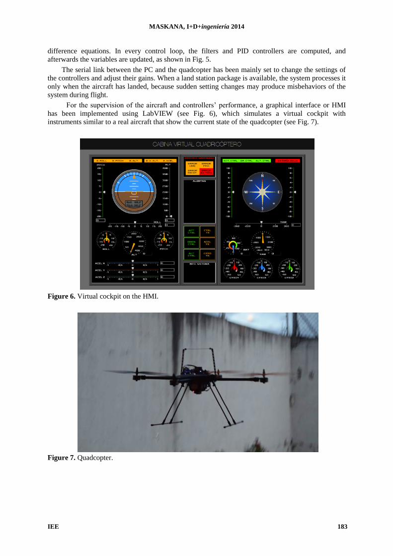
For the supervision of the aircraft and controllers’ performance, a graphical interface or HMI
has been implemented using LabVIEW (see Fig. 6), which simulates a virtual cockpit with
instruments similar to a real aircraft that show the current state of the quadcopter (see Fig. 7).
Figure 6. Virtual cockpit on the HMI.
Figure 7. Quadcopter.
MASKANA, I+D+ingeniería 2014
IEE 184
5. TESTS AND RESULTS
In the tests of the controllers during flight, the gains were adjusted, because the initial values of the
design did not show a suitable performance. The derivate gains in particular had to be drastically
decreased because their effect destabilized the system. A mild permanent oscillation of the aircraft
and the large derivative effect produced a bigger oscillation which led to the system destabilization.
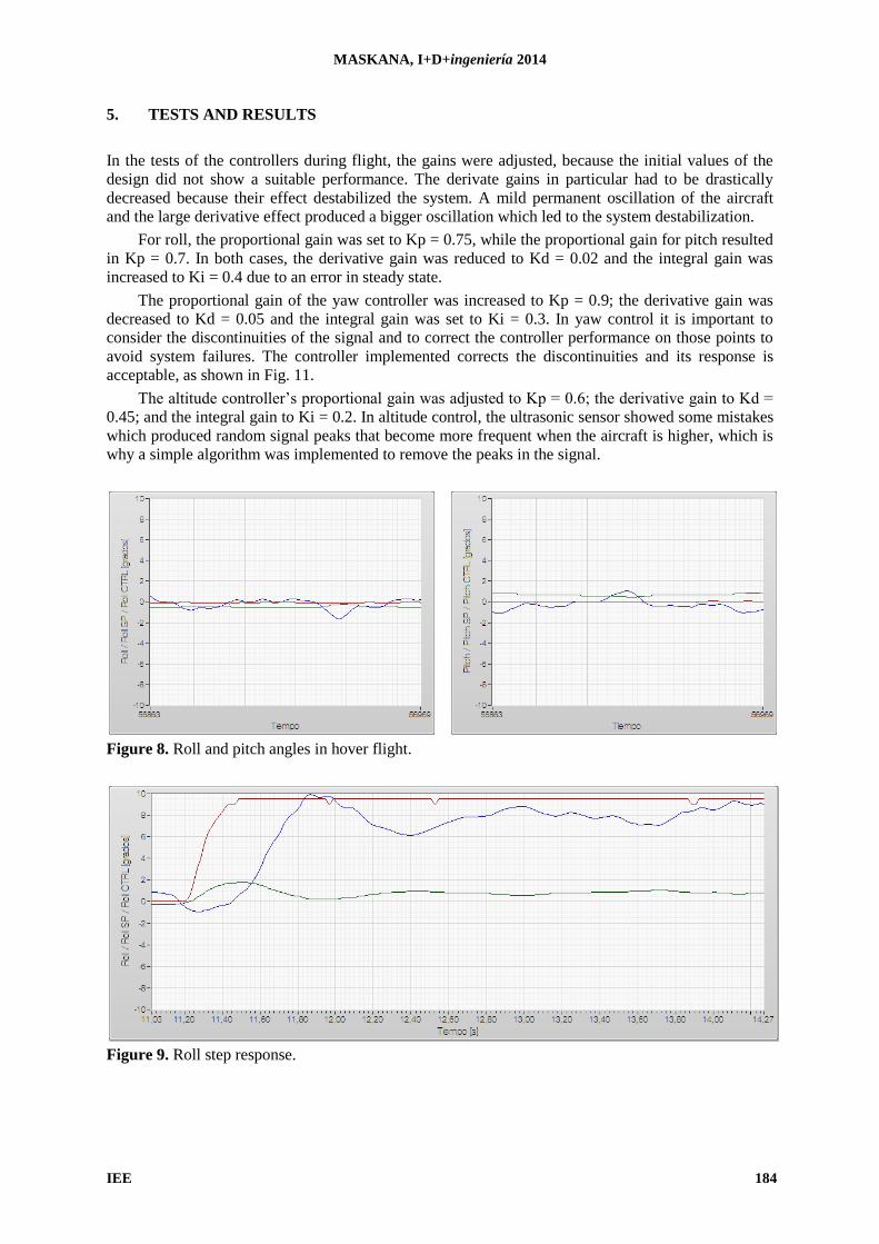
For roll, the proportional gain was set to Kp = 0.75, while the proportional gain for pitch resulted
in Kp = 0.7. In both cases, the derivative gain was reduced to Kd = 0.02 and the integral gain was
increased to Ki = 0.4 due to an error in steady state.
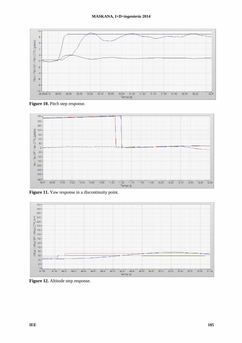
The proportional gain of the yaw controller was increased to Kp = 0.9; the derivative gain was
decreased to Kd = 0.05 and the integral gain was set to Ki = 0.3. In yaw control it is important to
consider the discontinuities of the signal and to correct the controller performance on those points to
avoid system failures. The controller implemented corrects the discontinuities and its response is
acceptable, as shown in Fig. 11.
The altitude controller’s proportional gain was adjusted to Kp = 0.6; the derivative gain to Kd =
0.45; and the integral gain to Ki = 0.2. In altitude control, the ultrasonic sensor showed some mistakes
which produced random signal peaks that become more frequent when the aircraft is higher, which is
why a simple algorithm was implemented to remove the peaks in the signal.
Figure 8. Roll and pitch angles in hover flight.
Figure 9. Roll step response.
MASKANA, I+D+ingeniería 2014
IEE 185
Figure 10. Pitch step response.
Figure 11. Yaw response in a discontinuity point.
Figure 12. Altitude step response.
MASKANA, I+D+ingeniería 2014
IEE 186
6. CONCLUSIONS
PID controllers are capable of stabilizing a complex system such as the quadcopter; however, the
influence of intense and long external disturbances affects the behavior of the controller.
The actual gains of the PID controllers differ from the original design gains because the math
model does not consider with exactitude all the effects acting on the quadcopter like the vibrations or
the oscillations of the system. Despite the nature of the system, whose behavior is practically a double
integrator, it has a steady state error, which is why the integral gains of all four controllers had to be
increased to obtain an improved response. Derivative gains were strongly reduced due to the mild
oscillation of the aircraft because its effect produces unstable control signals, which also produce
unstable behavior in the system.
A land system with a graphical interface is helpful to supervise the performance of the
quadcopter and the controllers during flight, and to adjust the controllers’ gains or setting if needed.
To improve the system behavior, in future works, the implementation of non-linear controls can
be made, which would be based on a non-simplified model, allowing wider ranges on roll and pitch
angles.
REFERENCES
Åström, K., T. Hägglund, 2009. Control PID avanzado. Pearson Educación, Prentice Hall, Madrid,
España.
Basdogan, C., 2004. Discrete PID controller. Robotics Courses, Koç Üniversitesi, Estambul.
Benavidez, J., J. Lambert, J. Aldo, M. Jamshidi, 2014. Landing of a quadcopter on a mobile base
using fuzzy logic, advance trends in soft computing. Studies in Fuzziness and Soft Computing,
312, 429-437.
Bouabdallah, S., P. Murrieri, R. Siegwart, 2005. Towards autonomous indoor micro VTOL.
Autonomous robots, 18(2), 171-183.
Bresciani, T., 2008. Modelling, identification and control of a quadrotor helicopter. Tesis de
Maestría, Department of Automatic Control, Lund University, Lund.
Castillo P., Lozano R., Dzul A., 2005.Stabilization of a mini rotorcraft with four rotors. Control
Systems, IEEE.
De Lellis, M., 2011. Modelling, identification and xontrol of a quadrotor aircraft. Czech Technical
University, Praga.
Escamilla, R., 2010. Diseño, construcción, instrumentación y control de un vehículo aéreo no
tripulado. Tesis de Ingeniería, Escuela Superior de Mecánica y Eléctrica, Instituto Politécnico
Nacional. México D.F.
Hald, U., M. Hesselbæk, 2005. Autonomous helicopter - Modelling and control. Aalborg University,
Aalborg.
Jiřinec, T., 2011. Stabilization and control of unmanned quadcopter. Tesis de Maestría, Czech
Technical University, Praga.
Natraj, A., L. Dieu Sang, D. Eynard, C. Demonceaux, P. Vasseur, 2013. Omnidirectional vision for
UAV: Applications to attitude, motion and altitude estimation for day and night conditions.
Journal of Intelligent & Robotic Systems, 69(1-4), 459-473.
Nex, F., F. Remondino, 2014. UAV for 3D mapping applications: A review. Applied Geomatics,
6(1), 1-15.