Embed Size (px)
Citation preview

CAI-QSP-01: QSeal Plug Customer Assembly Instructions
Document: CAI-QSP-01 Revision: 0
Release Date: 8/14/2019 Revision Date: --/--/----
QPC Fiber Optic, LLC www.qpcfiber.com
27612 El Lazo Road, Laguna Niguel, CA 92677 Ph: (949) 361-8855
Page 1 of 9
QSEAL PLUG CUSTOMER ASSEMBLY
INSTRUCTIONS
DOCUMENT: CAI-QSP-01 REVISION: 0 REVISION DATE: 8/14/2019
QPC CONFIDENTIAL
THE INFORMATION CONTAINED IN THIS DOCUMENT IS THE SOLE PROPERTY OF QPC FIBER OPTIC. ANY REPRODUCTION IN PART OR AS A WHOLE
WITHOUT THE WRITTEN PERMISSION OF QPC FIBER OPTIC IS PROHIBITED.

CAI-QSP-01: QSeal Plug Customer Assembly Instructions
Page 2 of 9
SCOPE
This document will describe the Assembly Instructions for the QPC QSeal Plug Connector in the 2-Channel and 4-Channel configurations.
MAIN COMPONENTS
BACKSHELL RUBBER GRIP w/ DUST COVER
STRAIN RELIEF & 3x SET SCREWS CABLE SEAL
CRIMP CRIMP SUPPORT
2-CHANNEL PLUG
SPACER INSERT W/ SCREWS TERMINI & SPRINGS BODY ASSEMBLY
OPTIONAL METAL BACKSHELL
METAL BACKSHELL w/ DUST COVER BACK NUT
BEND LIMITER NYLON WASHER
4-CHANNEL PLUG
SPACER INSERT W/ SCREW TERMINI & SPRINGS BODY ASSEMBLY

CAI-QSP-01: QSeal Plug Customer Assembly Instructions
Page 3 of 9
TOOL LIST
TORQUE TABLE
TK-060 QPC Cable and Connector Prep Tool Kit – (Equivalent tools may be used)
PT-062 Miller Kevlar Scissors (Carbon Molybdenum & Vanadium Steel Blade)
PT-500 Precise-Control .050” Screwdriver (1.27mm) Hex
PT-501 Precise-Control Screwdriver, 1/16" Hex
PT-503 Precise-Control Screwdriver, 5/64" (2mm) Hex
PT-502 Precise-Control Screwdriver, 3/32" Hex
PT-504 Precise-Control Screwdriver, 2.5mm Hex
PT-505 Screwdriver, Number 1 Phillips, 6-3/4" Overall Length
PT-506 Dial Torque-Measuring Wrench, 3/8" Square Drive, 0 to 150in.-lbs. and 0 to 18NM Torque
PT-536 Crow's Foot Wrench Adjustable 3/8" Square Drive 0.0-1.125"(0-28.57mm)
PT-545 Crow's Foot Wrench Adjustable 1/2" Square Drive .236-1.771" (6-45mm)
PT-546 3/8" Female x 1/2" Male Square Drive Adapter, Chrome
PT-532 Long-Nose Pliers with Flat Jaws, Cushion Grip, 6-3/4" Overall, Manual Jaws with Wire Cutter
PT-599 Hex Bit Set, 5 pcs (.050", 1/16", 5/64", 3/32", 2.5mm) 1/4" Shank, Overall Length 2”
PT-590 Torque-Measuring Screwdriver, Hex Drive, 2.5 to 11.5 in.-lbs. Adjustable Torque
PT-591 4" Drill Press Vise with 2 x Machined Plastic Jaws with Groove
PT-415 Square Driver Strap Wrench
TK-050 QPC QSeal Tool Kit – (Equivalent tools may be used)
PT-315 QSeal 4Ch Torque Fixture
PT-316 QSeal 2Ch Torque Fixture
PT-317 QSeal 2Ch and 4Ch Torque Fixture Stand
PT-540 Hydraulic Crimping Tool
PT-541 Die Set, 0.324 Hex, Hydraulic Hand Crimper
Component Strain Relief Backshell Set Screw Insert Screw
Torque Values 26 – 35 in-lb 57 – 62 in-lb 5 – 6 in-lb 3 – 4 in-lb
3.0 – 4.0 N • m 6.5 – 7.0 N • m .56 – .68 N • m .34 – .45 N • m
CAI-QSP-01: QSeal Plug Customer Assembly Instructions
Page 4 of 9
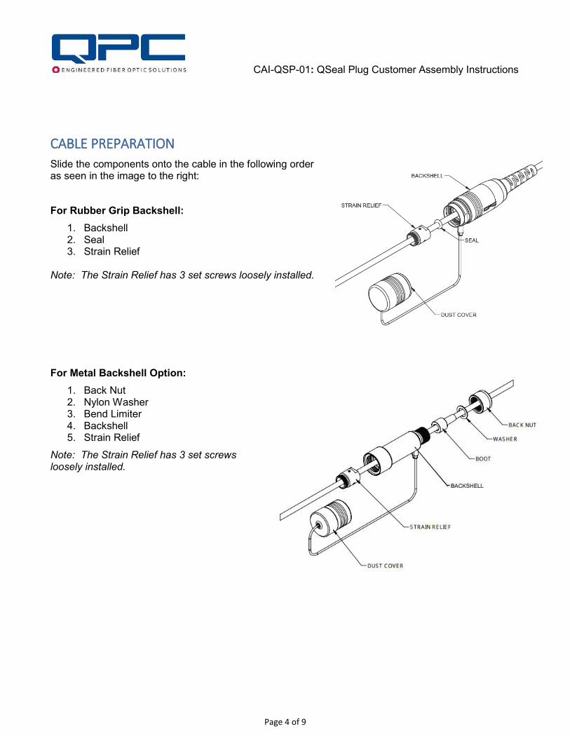
CABLE PREPARATION
Slide the components onto the cable in the following order as seen in the image to the right:
For Rubber Grip Backshell:
1. Backshell 2. Seal 3. Strain Relief
Note: The Strain Relief has 3 set screws loosely installed.
For Metal Backshell Option:
1. Back Nut 2. Nylon Washer 3. Bend Limiter 4. Backshell 5. Strain Relief
Note: The Strain Relief has 3 set screws loosely installed.

CAI-QSP-01: QSeal Plug Customer Assembly Instructions
Page 5 of 9
STRIP CABLE
Strip cable jacket approximately 6” (152 mm) from end and place Crimp Support over fiber and Kevlar so that it stops at the end of the jacket. Bend Kevlar back over the Crimp Support. Slide second Crimp over Kevlar and Crimp Support and secure with tape for crimping after termination and polishing.
TERMINATE
Use the 2-Channel or 4-Channel Stripping Length Diagrams seen below (and located at the end of this instruction) to Terminate and Polish the Fiber Optic Termini. Be sure to include a spring on each of the fibers. For Termination and Polishing details, reference CAI-TERM-01.
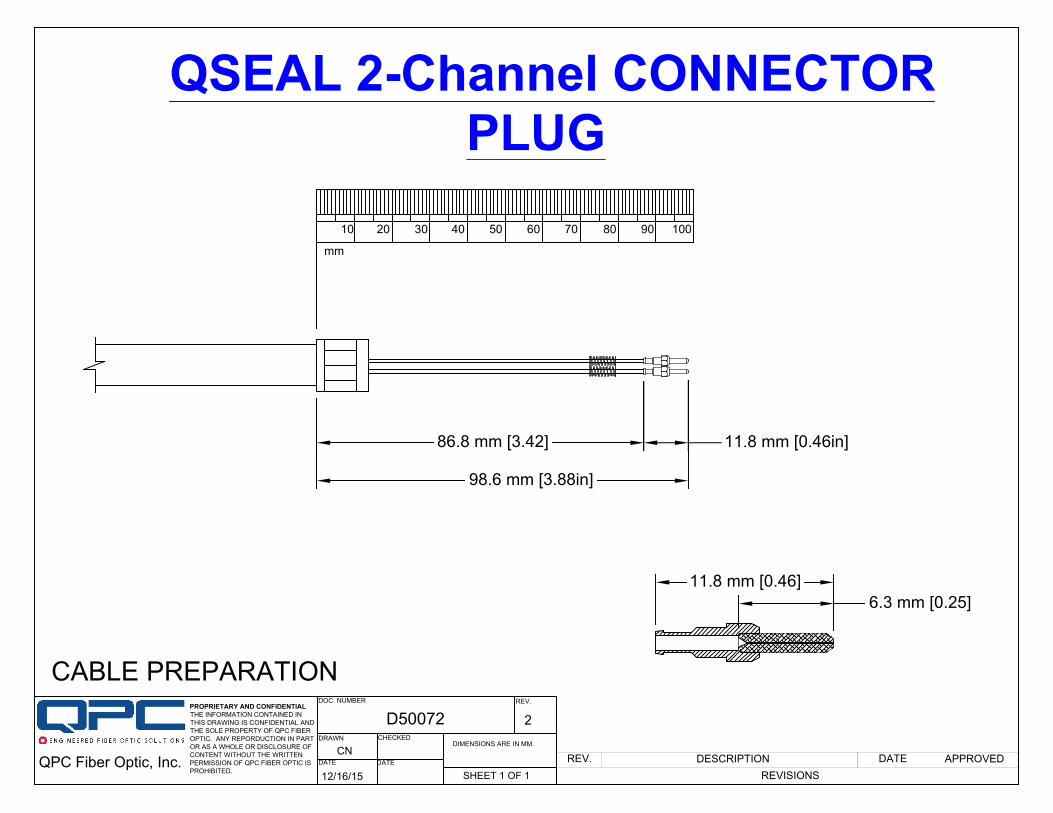
2-Channel Stripping Length Diagram
CAI-QSP-01: QSeal Plug Customer Assembly Instructions
Page 6 of 9
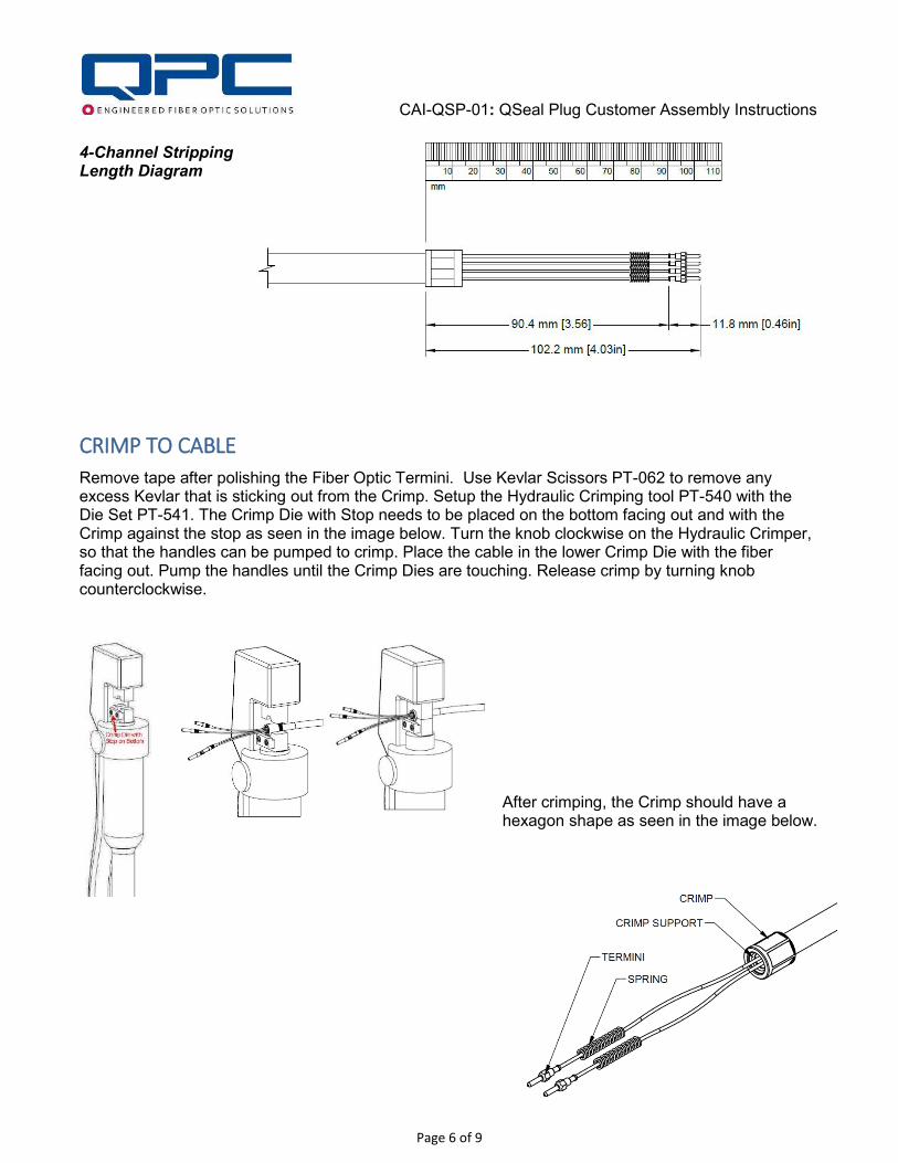
4-Channel Stripping Length Diagram
CRIMP TO CABLE
Remove tape after polishing the Fiber Optic Termini. Use Kevlar Scissors PT-062 to remove any excess Kevlar that is sticking out from the Crimp. Setup the Hydraulic Crimping tool PT-540 with the Die Set PT-541. The Crimp Die with Stop needs to be placed on the bottom facing out and with the Crimp against the stop as seen in the image below. Turn the knob clockwise on the Hydraulic Crimper, so that the handles can be pumped to crimp. Place the cable in the lower Crimp Die with the fiber facing out. Pump the handles until the Crimp Dies are touching. Release crimp by turning knob counterclockwise.
After crimping, the Crimp should have a hexagon shape as seen in the image below.
CAI-QSP-01: QSeal Plug Customer Assembly Instructions
Page 7 of 9
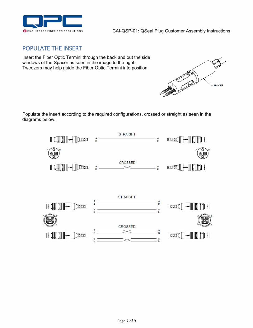
POPULATE THE INSERT
Insert the Fiber Optic Termini through the back and out the side windows of the Spacer as seen in the image to the right. Tweezers may help guide the Fiber Optic Termini into position.
Populate the insert according to the required configurations, crossed or straight as seen in the diagrams below.

CAI-QSP-01: QSeal Plug Customer Assembly Instructions
Page 8 of 9
Apply Loctite 243 on the Socket Head Cap Screw threads per manufacturer’s instructions or equivalent may be used and screw the Insert onto the Spacer using Hex Driver PT-503. Use Torque Driver PT-590 with Hex Bit 5/64” PT-599 and torque the Socket Head Cap Screw(s) to the values in the above Torque Table.
Pull Strain Relief to bottom of Spacer, apply Loctite on the Set Screw threads and tighten using Hex Driver PT-500. Use Torque Hex Driver PT-590 with Hex Bit .050” PT-599 and torque to the values in the above Torque Table. Perform a visual check by looking through the holes in the Spacer to make sure that the fiber is not twisted or kinked.
For the 2-channel Insert, ensure that the white mark line on the Insert is on the same side as the line on the spacer. This Insert has two Screws. The insert is NOT symmetrical, the termini are slightly below the center line. The insert should only go on one way.
The 4-channel insert does not have a white mark line since it can only go in one way. This Insert has only one screw in the middle.
CAI-QSP-01: QSeal Plug Customer Assembly Instructions
Page 9 of 9
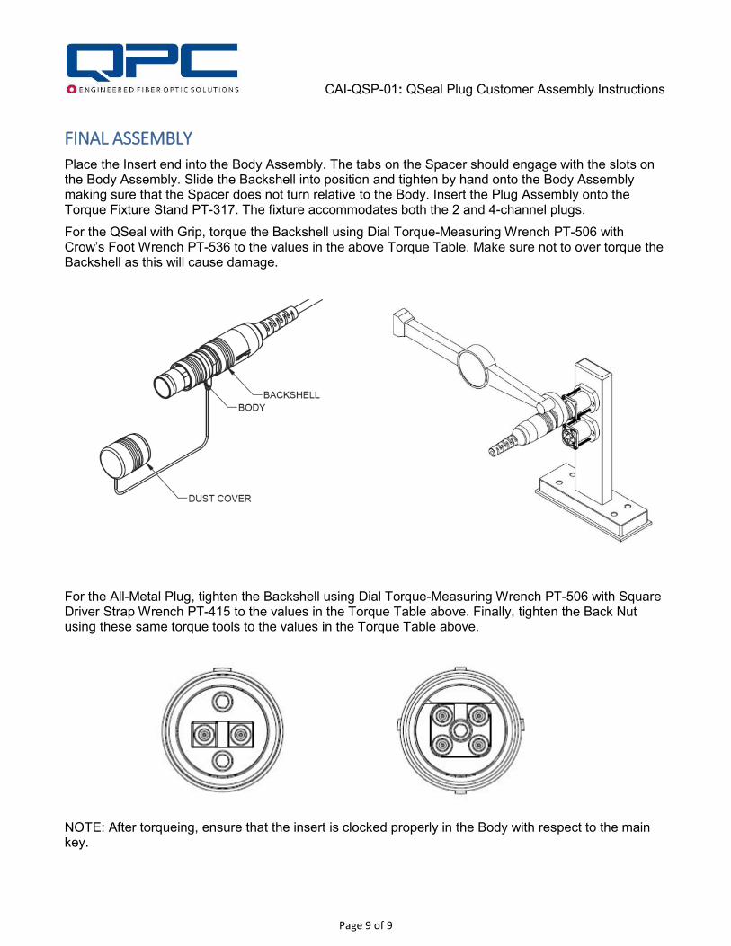
FINAL ASSEMBLY
Place the Insert end into the Body Assembly. The tabs on the Spacer should engage with the slots on the Body Assembly. Slide the Backshell into position and tighten by hand onto the Body Assembly making sure that the Spacer does not turn relative to the Body. Insert the Plug Assembly onto the Torque Fixture Stand PT-317. The fixture accommodates both the 2 and 4-channel plugs.
For the QSeal with Grip, torque the Backshell using Dial Torque-Measuring Wrench PT-506 with Crow’s Foot Wrench PT-536 to the values in the above Torque Table. Make sure not to over torque the Backshell as this will cause damage.
For the All-Metal Plug, tighten the Backshell using Dial Torque-Measuring Wrench PT-506 with Square Driver Strap Wrench PT-415 to the values in the Torque Table above. Finally, tighten the Back Nut using these same torque tools to the values in the Torque Table above.
NOTE: After torqueing, ensure that the insert is clocked properly in the Body with respect to the main key.
QPC Fiber Optic, Inc.
D50072
APPROVEDREVISIONS
DATEREV. DESCRIPTIONCN
CHECKEDDRAWN
DOC. NUMBER REV.
2
12/16/15
DIMENSIONS ARE IN MM.
DATE DATE
SHEET 1 OF 1
QSEAL 2-Channel CONNECTORPLUG
CABLE PREPARATIONPROPRIETARY AND CONFIDENTIALTHE INFORMATION CONTAINED IN THIS DRAWING IS CONFIDENTIAL AND THE SOLE PROPERTY OF QPC FIBER OPTIC. ANY REPORDUCTION IN PART OR AS A WHOLE OR DISCLOSURE OF CONTENT WITHOUT THE WRITTEN PERMISSION OF QPC FIBER OPTIC IS PROHIBITED.
10 6020 30 5040 70 80 90
mm
98.6 mm [3.88in]
11.8 mm [0.46in]
100
86.8 mm [3.42]
11.8 mm [0.46]6.3 mm [0.25]

QPC Fiber Optic, Inc.
D50073
APPROVEDREVISIONS
DATEREV. DESCRIPTIONCN
CHECKEDDRAWN
DOC. NUMBER REV.
2
12/16/15
DIMENSIONS ARE IN MM.
DATE DATE
SHEET 1 OF 1
QSEAL 4-Channel CONNECTORPLUG
CABLE PREPARATIONPROPRIETARY AND CONFIDENTIALTHE INFORMATION CONTAINED IN THIS DRAWING IS CONFIDENTIAL AND THE SOLE PROPERTY OF QPC FIBER OPTIC. ANY REPORDUCTION IN PART OR AS A WHOLE OR DISCLOSURE OF CONTENT WITHOUT THE WRITTEN PERMISSION OF QPC FIBER OPTIC IS PROHIBITED.
10 6020 30 5040 70 80 90
mm
102.2 mm [4.03in]
11.8 mm [0.46in]
100
90.4 mm [3.56]
110
11.8 mm [0.46]6.3 mm [0.25]