Embed Size (px)
Citation preview
QSDT8DP DVR User’s Manual
i
QSDT8DP
DVR User’s Manual
For H.264-240 FPS /8-channel digital video recorder
All rights reserved
Rev 120209

QSDT8DP User’s Manual
ii
CAUTION Please read this user manual carefully to ensure that you can use the
device correctly and safely
The contents of this manual are subject to change without notice
This device should be operated only with the power source supplied
with the unit. The power supply voltage must be verified before using. If
not going to be used for a long time, unplug the unit from the outlet
Do not install this device near any heat sources such as radiators, heat
registers, stoves or other devices that produce heat
Do not install this device near water. Clean only with a dry cloth
Do not block any ventilation openings, and make sure the area around
the machine is well ventilated
This machine is designed for indoor use. Do not expose the machine to
water or a moist environment. If any solid or liquid gets into the machine’s
case, please cut off the power supply immediately, and have the unit
checked be a qualified technician before restart
Refer all servicing to qualified service personnel. There are no parts in
the unit you can service yourself.
QSDT8DP DVR User’s Manual
iii
CONTENTS CHAPTER 1 Introduction ..................................................................................... 1
1.1 DVR Introduction ............................................................................................ 1 1.2 Main Features ................................................................................................ 1 1.3 DVR Introduction ............................................................................................ 1 1.4 Main Features ................................................................................................ 2
CHAPTER 2 Hardware Installation ...................................................................... 4 2.1 Installing Hard Drive ....................................................................................... 4 2.2 Front Panel Layout ......................................................................................... 5 2.3 Rear Panel Layout ......................................................................................... 6
2.3.1 Installing Sensors & Alarms (optional) ........................................................................... 6 2.4 Remote Control .............................................................................................. 8 2.5 Controlling with a Mouse ................................................................................ 9
2.5.1 Connecting Mouse ........................................................................................................ 9 2.5.2 Using Mouse ................................................................................................................. 9
CHAPTER 3 Basic Function Instructions ............................................................ 10 3.1 Power On/Off ............................................................................................... 10 3.2 Login & User Management ........................................................................... 11 3.3 Recording ..................................................................................................... 14
3.3.1 Record Setup .............................................................................................................. 14 3.3.2 Manual Recording ....................................................................................................... 15 3.3.3 Scheduled Recording .................................................................................................. 15 3.3.4 Motion Detection Recording ........................................................................................ 16 3.3.5 Alarm Recording ......................................................................................................... 17
3.4 Playback ....................................................................................................... 18 3.5 Backup & View ............................................................................................. 20 3.6 PTZ Control .................................................................................................. 26
CHAPTER 4 Menu Setup Guide.......................................................................... 28 4.1 Menu Navigation .......................................................................................... 28 4.2 Main Menu Setup ......................................................................................... 29
4.2.1 Basic Configuration ..................................................................................................... 30 4.2.2 Live Configuration ....................................................................................................... 31 4.2.3 Record Configuration .................................................................................................. 32 4.2.4 Schedule Configuration ............................................................................................... 33 4.2.5 Alarm Configuration .................................................................................................... 33 4.2.6 Motion Configuration ................................................................................................... 35 4.2.7 Network Configuration................................................................................................. 36 4.2.8 P.T.Z Configuration ...................................................................................................... 38 4.2.9 User Configuration ...................................................................................................... 39 4.2.10 Tools Configuration ................................................................................................... 39
CHAPTER 5 Managing the DVR ....................................................................... 40 5.1 Formatting the Hard Disk ............................................................................. 40 5.2 Updating Firmware ....................................................................................... 40 5.3 Load Default Setup ...................................................................................... 41 5.4 Check System Information ........................................................................... 41 5.5 Check System Log ....................................................................................... 43 5.6 Check On-line Network Users ...................................................................... 44 5.7 Lock & Delete Files ...................................................................................... 45
QSDT8DP User’s Manual
iv
CHAPTER 6 Remote Surveillance ................................................................... 46 6.1 Accessing the DVR ...................................................................................... 46
6.1.1 On LAN....................................................................................................................... 46 6.1.2 On WAN ..................................................................................................................... 47
6.2 Remote Viewing ........................................................................................... 48 6.3 Remote Playback &Backup .......................................................................... 52
6.3.1 Remote Playback ........................................................................................................ 52 6.3.2 Remote Backup .......................................................................................................... 54
6.4 Remote Menu Configuration ........................................................................ 55 6.5 Remote DVR Management .......................................................................... 56
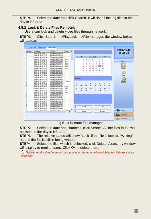
6.5.1 Check System Log Remotely ...................................................................................... 56 6.5.2 Lock & Delete Files Remotely ..................................................................................... 57
CHAPTER 7 Mobile Surveillance ........................................................................ 58 7.1 Accessing From Phones with WinCE ........................................................... 58 7.2 Accessing From Phones with Symbian ........................................................ 60 7.3 Accessing From iPhones .............................................................................. 62
Appendix A FAQs ............................................................................................. 67 Appendix B Calculating Recording Capacity ................................................. 71 Appendix C Compatible Devices .................................................................... 72 Appendix D DVR Specifications ...................................................................... 73 Q-SEE Product Warranty ………………………………………………………………75 Customer Information Card .................................................................................... 75
QSDT8DP DVR User’s Manual
1
CHAPTER 1 Introduction 1.1 DVR Introduction
This DVR uses high performance video processing chips and an embedded Linux system. It utilizes many advanced technologies, such as standard H.264 with low bit rate, Dual Stream, SATA interface, VGA output, supports access by mouse, IE browser supported with full remote control, mobile viewing by cell phones, etc. it has very powerful functions and high stability. It is widely used in banking, telecommunication, transportation, factories, warehouses, irrigation, etc.
1.2 Main Features COMPRESSION FORMAT
• Standard H.264 compression with low bit rate. Backup file can be played by normal player, without any software or codec installed.
LIVE SURVEILLANCE • Supports VGA output • Supports channel security by hiding live display • Displays the local record state and basic information • Supports full control with USB mouse • Supports system locking and unlocking
RECORDING MEDIA • Supports 2 SATA HDDs to record for long time periods
1.3 DVR Introduction This DVR uses high performance video processing chips and an embedded Linux system. It utilizes many advanced technologies, such as standard H.264 with low bit rate, Dual Stream, SATA interface, VGA output, supports access by mouse, IE browser supported with full remote control, mobile viewing by cell phones, etc. it has very powerful functions and high stability. It is widely used in banking, telecommunication, transportation, factories, warehouses, irrigation, etc.

QSDT8DP DVR User’s Manual
2
1.4 Main Features COMPRESSION FORMAT
• Standard H.264 compression with low bit rate. Backup file can be played by normal player, without any software or codec installed.
LIVE SURVEILLANCE • Supports VGA output • Supports channel security by hiding live display • Displays the local record state and basic information • Supports full control with USB mouse • Supports system locking and unlocking
RECORDING MEDIA • Supports 2 SATA HDDs to record for long time periods
BACKUP • Supports USB flash drive for backup • Supports saving recorded files to a remote computer through internet
RECORD & PLAYBACK • Record modes: Manual, Schedule, Motion detection and Sensor alarm recording • Supports recycling after HDD is full • Resolution, frame rate and picture quality adjustable for each channel separately • 64MB for every video file packaging • 4 audio channels available • Two record search modes: time search and event search • Supports single and 4 screen playback • Supports deleting and locking the recorded files individually • Supports remote playback in Internet Explorer through LAN or internet
ALARM • 16 channel alarm input and 4 channel alarm output available • Supports schedule for motion detection and sensor alarm • Supports pre-recording and post recording • Supports linked channel recording once a motion or sensor alarm is triggered on certain channels • Supports linked PTZ presets and auto cruise on the corresponding channel
PTZ CONTROL • Supports various PTZ protocols PelcoP, PelcoD, LILIN, MINKING, NEON, STAR, VIDO, DSCP, VISCA,
QSDT8DP DVR User’s Manual
3
and RANGE • Supports various PTZ presets and 16 auto cruise tracks • Supports remote PTZ control through internet
SECURITY • Two level user group management: advance and normal, rights authorized by administrator • Support one administrator and 15 users. • Support event log recording and checking, unlimited events
NETWORK • Supports TCP/IP, DHCP, PPPoE, DDNS protocol • Supports IE browser to do remote viewing • Supports a maximum of 5 connections simultaneously • Supports dual stream. Network stream adjustable independently to fit the network bandwidth and environment. • Supports picture snap and color adjustment in remote live view • Supports remote time and event search, mouse drag search, single channel playback with picture snap • Supports remote PTZ control with preset and auto cruise • Supports remote full menu setup, changing all the DVR parameters remotely • Supports mobile surveillance by smart phones or PDA with Symbian or WinCE OS and iphones on 3G networks. • Supports CMS to manage multiple devices on internet.
QSDT8DP DVR User’s Manual
4
CHAPTER 2 Hardware Installation Note: Check the unit and the accessories before using the DVR.
Please disconnect the power before connecting to other devices. Don't hot plug in/out
2.1 Installing Hard Drive Note: 1. Supports two SATA hard drives.
2. Please calculate HDD capacity needed according to the recording setting. Please refer to “Appendix B Calculate Recording Capacity”.
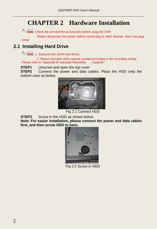
STEP1 Unscrew and open the top cover STEP2 Connect the power and data cables. Place the HDD onto the bottom case as below.
Fig 2.1 Connect HDD
STEP3 Screw in the HDD as shown below. Note: For easier installation, please connect the power and data cables first, and then screw HDD to base.
Fig 2.2 Screw in HDD
QSDT8DP DVR User’s Manual
5
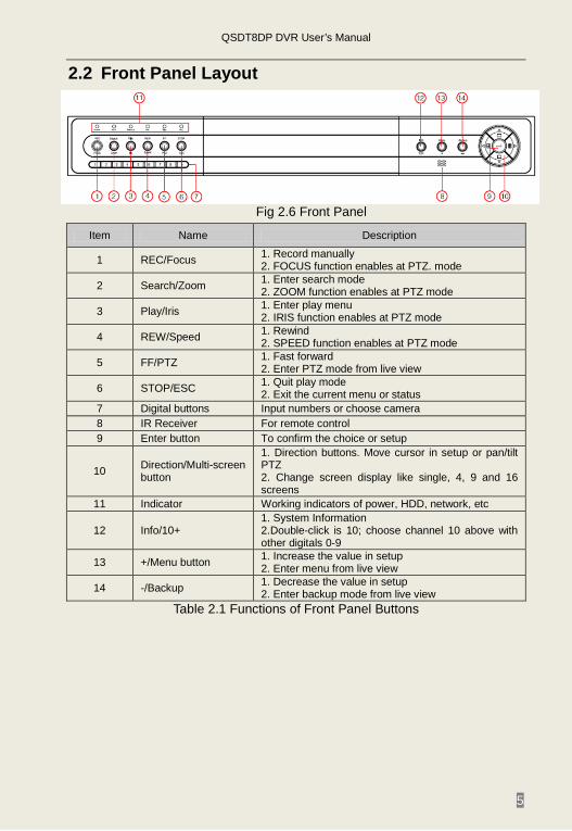
2.2 Front Panel Layout
Fig 2.6 Front Panel
Item Name Description
1 REC/Focus 1. Record manually 2. FOCUS function enables at PTZ. mode
2 Search/Zoom 1. Enter search mode 2. ZOOM function enables at PTZ mode
3 Play/Iris 1. Enter play menu 2. IRIS function enables at PTZ mode
4 REW/Speed 1. Rewind 2. SPEED function enables at PTZ mode
5 FF/PTZ 1. Fast forward 2. Enter PTZ mode from live view
6 STOP/ESC 1. Quit play mode 2. Exit the current menu or status
7 Digital buttons Input numbers or choose camera 8 IR Receiver For remote control 9 Enter button To confirm the choice or setup
10 Direction/Multi-screen button
1. Direction buttons. Move cursor in setup or pan/tilt PTZ 2. Change screen display like single, 4, 9 and 16 screens
11 Indicator Working indicators of power, HDD, network, etc
12 Info/10+ 1. System Information 2.Double-click is 10; choose channel 10 above with other digitals 0-9
13 +/Menu button 1. Increase the value in setup 2. Enter menu from live view
14 -/Backup 1. Decrease the value in setup 2. Enter backup mode from live view
Table 2.1 Functions of Front Panel Buttons
QSDT8DP DVR User’s Manual
6
2.3 Rear Panel Layout
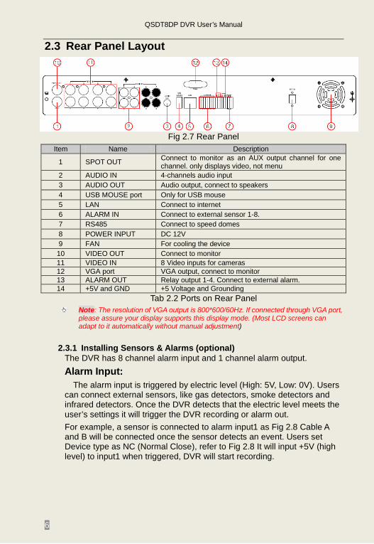
Fig 2.7 Rear Panel
Item Name Description
1 SPOT OUT Connect to monitor as an AUX output channel for one channel. only displays video, not menu
2 AUDIO IN 4-channels audio input 3 AUDIO OUT Audio output, connect to speakers 4 USB MOUSE port Only for USB mouse 5 LAN Connect to internet 6 ALARM IN Connect to external sensor 1-8. 7 RS485 Connect to speed domes 8 POWER INPUT DC 12V 9 FAN For cooling the device 10 VIDEO OUT Connect to monitor 11 VIDEO IN 8 Video inputs for cameras 12 VGA port VGA output, connect to monitor 13 ALARM OUT Relay output 1-4. Connect to external alarm. 14 +5V and GND +5 Voltage and Grounding
Tab 2.2 Ports on Rear Panel Note: The resolution of VGA output is 800*600/60Hz. If connected through VGA port,
please assure your display supports this display mode. (Most LCD screens can adapt to it automatically without manual adjustment)
2.3.1 Installing Sensors & Alarms (optional) The DVR has 8 channel alarm input and 1 channel alarm output. Alarm Input:
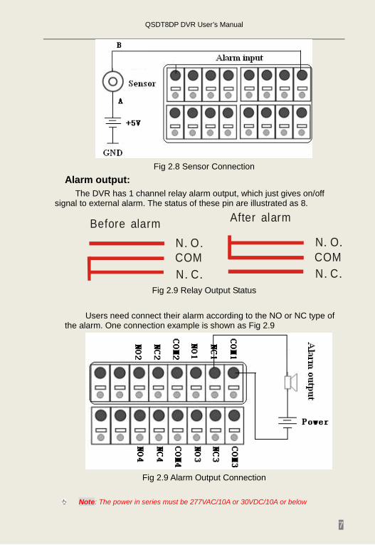
The alarm input is triggered by electric level (High: 5V, Low: 0V). Users can connect external sensors, like gas detectors, smoke detectors and infrared detectors. Once the DVR detects that the electric level meets the user’s settings it will trigger the DVR recording or alarm out. For example, a sensor is connected to alarm input1 as Fig 2.8 Cable A and B will be connected once the sensor detects an event. Users set Device type as NC (Normal Close), refer to Fig 2.8 It will input +5V (high level) to input1 when triggered, DVR will start recording.
QSDT8DP DVR User’s Manual
7
Fig 2.8 Sensor Connection
Alarm output: The DVR has 1 channel relay alarm output, which just gives on/off
signal to external alarm. The status of these pin are illustrated as 8.
N O. .COMN C. .
N O. .COMN C. .
Before alarm After alarm
Fig 2.9 Relay Output Status
Users need connect their alarm according to the NO or NC type of
the alarm. One connection example is shown as Fig 2.9
Fig 2.9 Alarm Output Connection
Note: The power in series must be 277VAC/10A or 30VDC/10A or below
QSDT8DP DVR User’s Manual
8
2.4 Remote Control The remote control uses two AAA batteries, instructions for loading:
STEP1 Open the battery cover of the Remote Control STEP2 Insert batteries with the poles (+ and -) correctly aligned STEP3 Replace the battery cover
Note: If remote does not function check the following: 1. Check polarity of batteries 2. Check the remaining charge in the batteries 3. Check to see if remote control sensor is blocked If it doesn't still work, exchange for a new remote control or contact your dealer.
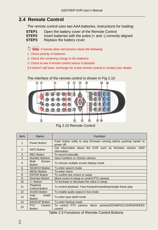
The interface of the remote control is shown in Fig 2.10
Fig 2.10 Remote Control
Item Name Function
1 Power Button Push button softly to stop firmware running before pushing harder to power off.
2 INFO Button Get information about the DVR such as firmware version, HDD information
3 REC Button To record manually 4 Number Buttons Input numbers or choose camera
5 Multi Screen Button To choose multiple screen display mode
6 SEARCH Button To enter search mode 7 MENU Button To enter menu 8 ENTER Button To confirm the choice or setup 9 Direction Button Move cursor in setup or control PTZ camera 10 +/- Button To increase or decrease the value in setup
11 Playback Control Button To control playback. Fast forward/rewind/stop/single frame play
12 AUDIO Button To enable audio output in live mode
13 Auto Dwell Button To enter auto dwell mode
14 BACKUP Button To enter backup mode
15 PTZ Control Button
To control PTZ camera. Move camera/ZOOM/FOCUS/IRIS/SPEED control
Table 2.3 Functions of Remote Control Buttons
QSDT8DP DVR User’s Manual
9
2.5 Controlling with a Mouse 2.5.1 Connecting Mouse
DVR supports USB mouse through the ports on the rear panel, please refer to Fig 2.10 Remote Control
Note: If mouse is not detected or doesn't work, check below: 1. Unplug/re-plug several times 2. Power off/on several times 3. Try another mouse
2.5.2 Using Mouse In live view:
Click left mouse button on one camera to display full screen. Click again to return to the previous screen display.
Click right button to show the control bar at the bottom of the screen as in Fig 2.10 Remote Control. Here are all the controls and setup. Click right mouse button again to hide the control bar. In setup:
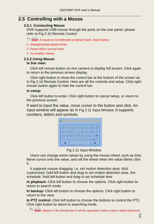
Click left button to enter. Click right button to cancel setup, or return to the previous screen. If want to input the value, move cursor to the button and click. An input window will appear as in Fig 2.11 Input Window. It supports numbers, letters and symbols.
Fig 2.11 Input Window
Users can change some values by using the mouse wheel, such as time. Move cursor onto the value, and roll the wheel when the value blinks click it.
It supports mouse dragging, i.e. set motion detection area: click customized, hold left button and drag to set motion detection area. Set schedule: hold left button and drag to set schedule time In playback: Click left button to choose the options. Click right button to return to search mode. In backup: Click left button to choose the options. Click right button to return to live view. In PTZ control: Click left button to choose the buttons to control the PTZ. Click right button to return to searching mode.
Note: Mouse is the default tool in all the operations below unless stated otherwise.
QSDT8DP DVR User’s Manual
10
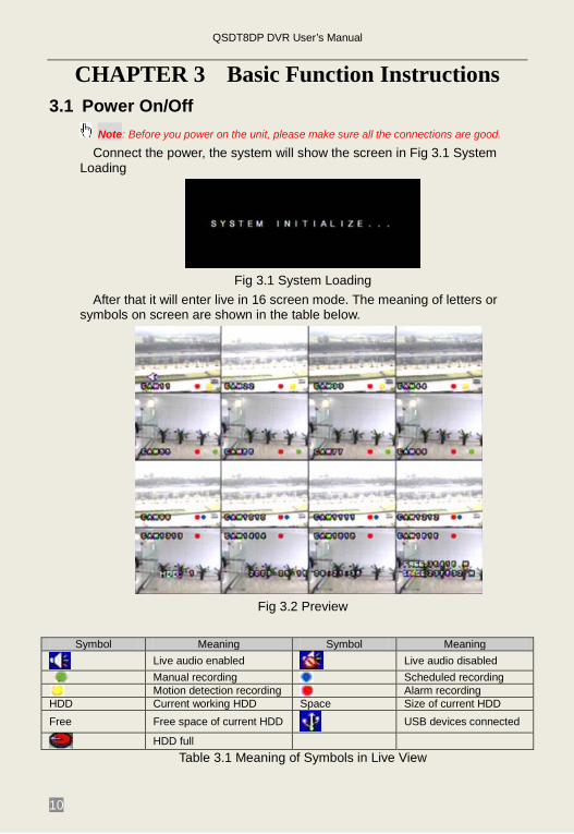
CHAPTER 3 Basic Function Instructions 3.1 Power On/Off
Note: Before you power on the unit, please make sure all the connections are good.
Connect the power, the system will show the screen in Fig 3.1 System Loading
Fig 3.1 System Loading
After that it will enter live in 16 screen mode. The meaning of letters or symbols on screen are shown in the table below.
Fig 3.2 Preview
Symbol Meaning Symbol Meaning
Live audio enabled Live audio disabled
Manual recording Scheduled recording Motion detection recording Alarm recording
HDD Current working HDD Space Size of current HDD Free Free space of current HDD USB devices connected
HDD full Table 3.1 Meaning of Symbols in Live View
QSDT8DP DVR User’s Manual
11
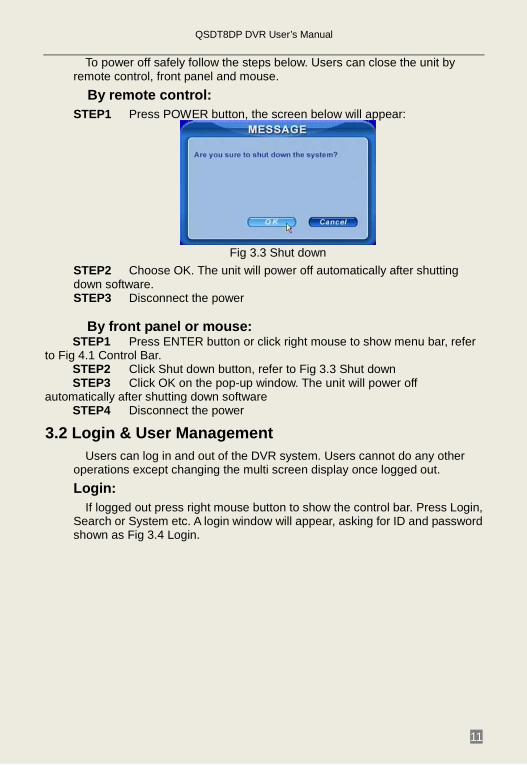
To power off safely follow the steps below. Users can close the unit by remote control, front panel and mouse.
By remote control: STEP1 Press POWER button, the screen below will appear:
Fig 3.3 Shut down
STEP2 Choose OK. The unit will power off automatically after shutting down software. STEP3 Disconnect the power
By front panel or mouse:
STEP1 Press ENTER button or click right mouse to show menu bar, refer to Fig 4.1 Control Bar.
STEP2 Click Shut down button, refer to Fig 3.3 Shut down STEP3 Click OK on the pop-up window. The unit will power off
automatically after shutting down software STEP4 Disconnect the power
3.2 Login & User Management Users can log in and out of the DVR system. Users cannot do any other
operations except changing the multi screen display once logged out. Login:
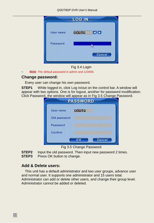
If logged out press right mouse button to show the control bar. Press Login, Search or System etc. A login window will appear, asking for ID and password shown as Fig 3.4 Login.
QSDT8DP DVR User’s Manual
12
Fig 3.4 Login
Note: The default password is admin and 123456.
Change password: Every user can change his own password.
STEP1 While logged in, click Log in/out on the control bar. A window will appear with two options. One is for logout, another for password modification. Click Password, the window will appear as in Fig 3.5 Change Password.
Fig 3.5 Change Password
STEP2 Input the old password. Then input new password 2 times. STEP3 Press OK button to change.
Add & Delete users:
This unit has a default administrator and two user groups, advance user and normal user. It supports one administrator and 15 users total. Administrator can add or delete other users, and change their group level. Administrator cannot be added or deleted.
QSDT8DP DVR User’s Manual
13
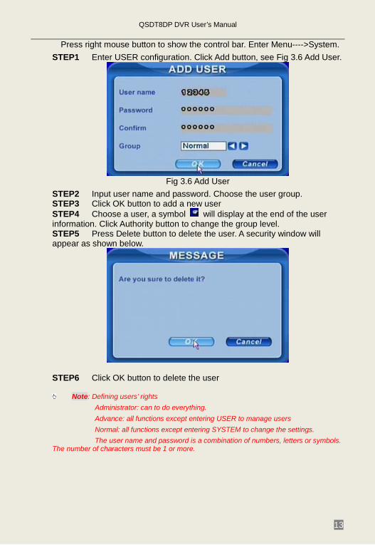
Press right mouse button to show the control bar. Enter Menu---->System. STEP1 Enter USER configuration. Click Add button, see Fig 3.6 Add User.
Fig 3.6 Add User
STEP2 Input user name and password. Choose the user group. STEP3 Click OK button to add a new user STEP4 Choose a user, a symbol will display at the end of the user information. Click Authority button to change the group level. STEP5 Press Delete button to delete the user. A security window will appear as shown below.
STEP6 Click OK button to delete the user
Note: Defining users’ rights Administrator: can to do everything. Advance: all functions except entering USER to manage users Normal: all functions except entering SYSTEM to change the settings. The user name and password is a combination of numbers, letters or symbols.
The number of characters must be 1 or more.
QSDT8DP DVR User’s Manual
14
3.3 Recording 3.3.1 Record Setup
Users need to install and format a HDD, and set all the recording parameters before recording.
Note: Some vendors sell the DVR with a hard drive already installed, if this is the case you just need to set the recording parameters.
There are four recording modes. Users can enable them simultaneously, but only one recording mode works at a time. They have different priorities, the priority order is below: Motion detection recording > Sensor recording > Manual recording > Timer recording
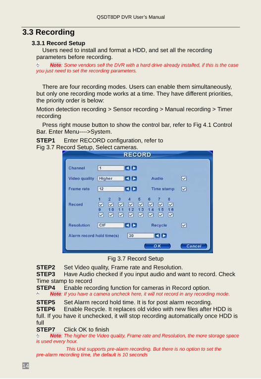
Press right mouse button to show the control bar, refer to Fig 4.1 Control Bar. Enter Menu---->System. STEP1 Enter RECORD configuration, refer to Fig 3.7 Record Setup, Select cameras.
Fig 3.7 Record Setup STEP2 Set Video quality, Frame rate and Resolution. STEP3 Have Audio checked if you input audio and want to record. Check Time stamp to record STEP4 Enable recording function for cameras in Record option.
Note: If you have a camera uncheck here, it will not record in any recording mode.
STEP5 Set Alarm record hold time. It is for post alarm recording. STEP6 Enable Recycle. It replaces old video with new files after HDD is full. If you have it unchecked, it will stop recording automatically once HDD is full STEP7 Click OK to finish
Note: The higher the Video quality, Frame rate and Resolution, the more storage space is used every hour.
This Unit supports pre-alarm recording. But there is no option to set the pre-alarm recording time, the default is 10 seconds
QSDT8DP DVR User’s Manual
15
3.3.2 Manual Recording Just press REC button on the front panel after quitting system setup. Press
Stop button to stop recording. Or press REC button on remote control, click again to stop. Or click REC button on the control bar with mouse, click again to stop.
3.3.3 Scheduled Recording Users can set different schedule times for every day of the week. If you want
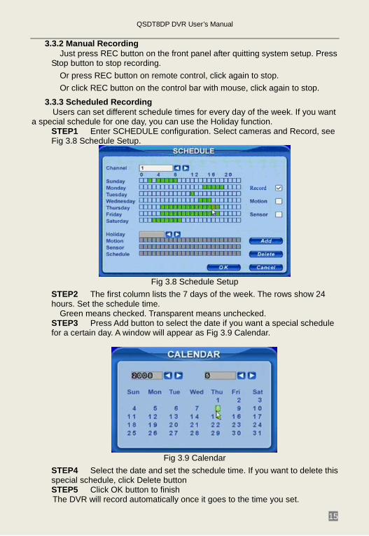
a special schedule for one day, you can use the Holiday function. STEP1 Enter SCHEDULE configuration. Select cameras and Record, see Fig 3.8 Schedule Setup.
Fig 3.8 Schedule Setup
STEP2 The first column lists the 7 days of the week. The rows show 24 hours. Set the schedule time.
Green means checked. Transparent means unchecked. STEP3 Press Add button to select the date if you want a special schedule for a certain day. A window will appear as Fig 3.9 Calendar.
Fig 3.9 Calendar
STEP4 Select the date and set the schedule time. If you want to delete this special schedule, click Delete button STEP5 Click OK button to finish The DVR will record automatically once it goes to the time you set.
QSDT8DP DVR User’s Manual
16
3.3.4 Motion Detection Recording This unit supports recording channels and PTZ linking. This means it will
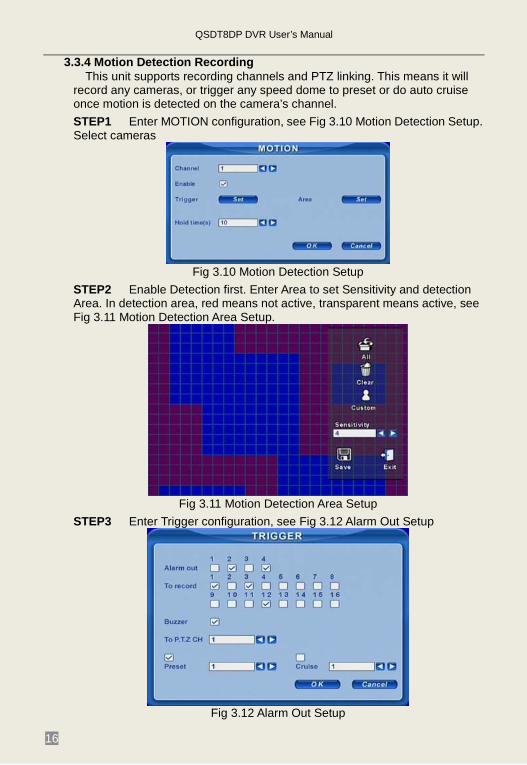
record any cameras, or trigger any speed dome to preset or do auto cruise once motion is detected on the camera’s channel. STEP1 Enter MOTION configuration, see Fig 3.10 Motion Detection Setup. Select cameras
Fig 3.10 Motion Detection Setup
STEP2 Enable Detection first. Enter Area to set Sensitivity and detection Area. In detection area, red means not active, transparent means active, see Fig 3.11 Motion Detection Area Setup.
Fig 3.11 Motion Detection Area Setup
STEP3 Enter Trigger configuration, see Fig 3.12 Alarm Out Setup
Fig 3.12 Alarm Out Setup
QSDT8DP DVR User’s Manual
17
STEP4 Select alarm out and recording channels. It can trigger any alarm out and cameras to record once motion is detected. STEP5 Enable or disable Buzzer on board. Select speed dome (PTZ) and enable preset or auto cruise. Press OK to save STEP6 Set Hold time. It is the interval time between two consecutive motion events. If a second motion event is detected during the Hold time, it is recognized as a continuation of the first motion event. If a second motion is detected after Hold time, this motion and the previous are recognized as two different motion events. STEP7 Click OK to save settings STEP8 Enter SCHEDULE configuration. Select Motion and relative cameras to set, refer to 3.3.3 Schedule recording.
Note: About preset and auto cruise, users can only select one or the other. The actual post alarm record time equals Hold time in RECORD and Hold time in MOTION
3.3.5 Alarm Recording This unit supports recording channels and PTZ linking after alarm.
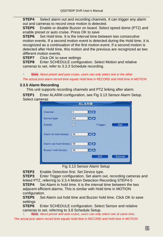
STEP1 Enter ALARM configuration, see Fig 3.13 Sensor Alarm Setup. Select cameras
Fig 3.13 Sensor Alarm Setup
STEP2 Enable Detection first. Set Device type. STEP3 Enter Trigger configuration. Set alarm out, recording cameras and linked PTZ, referring to 3.3.4 Motion Detection Recording STEP4-5 STEP4 Set Alarm in hold time. It is the interval time between the two adjacent efficient alarms. This is similar with Hold time in MOTION configuration. STEP5 Set Alarm out hold time and Buzzer hold time. Click OK to save settings STEP6 Enter SCHEDULE configuration. Select Sensor and relative cameras to set, referring to 3.8 Schedule Setup.
Note: About preset and auto cruise, users can only select one at same time. The actual post alarm record time equals Hold time in RECORD and Hold time in MOTION
QSDT8DP DVR User’s Manual
18
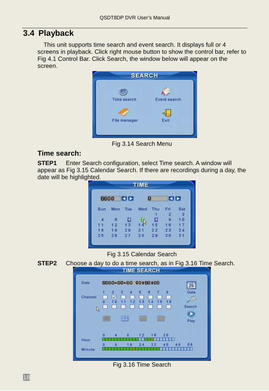
3.4 Playback This unit supports time search and event search. It displays full or 4
screens in playback. Click right mouse button to show the control bar, refer to Fig 4.1 Control Bar. Click Search, the window below will appear on the screen.
Fig 3.14 Search Menu
Time search: STEP1 Enter Search configuration, select Time search. A window will appear as Fig 3.15 Calendar Search. If there are recordings during a day, the date will be highlighted.
Fig 3.15 Calendar Search
STEP2 Choose a day to do a time search, as in Fig 3.16 Time Search.
Fig 3.16 Time Search
QSDT8DP DVR User’s Manual
19
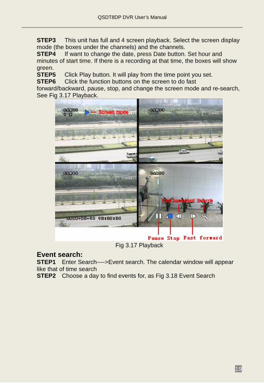
STEP3 This unit has full and 4 screen playback. Select the screen display mode (the boxes under the channels) and the channels. STEP4 If want to change the date, press Date button. Set hour and minutes of start time. If there is a recording at that time, the boxes will show green. STEP5 Click Play button. It will play from the time point you set. STEP6 Click the function buttons on the screen to do fast forward/backward, pause, stop, and change the screen mode and re-search, See Fig 3.17 Playback.
Fig 3.17 Playback
Event search: STEP1 Enter Search---->Event search. The calendar window will appear like that of time search STEP2 Choose a day to find events for, as Fig 3.18 Event Search
QSDT8DP DVR User’s Manual
20
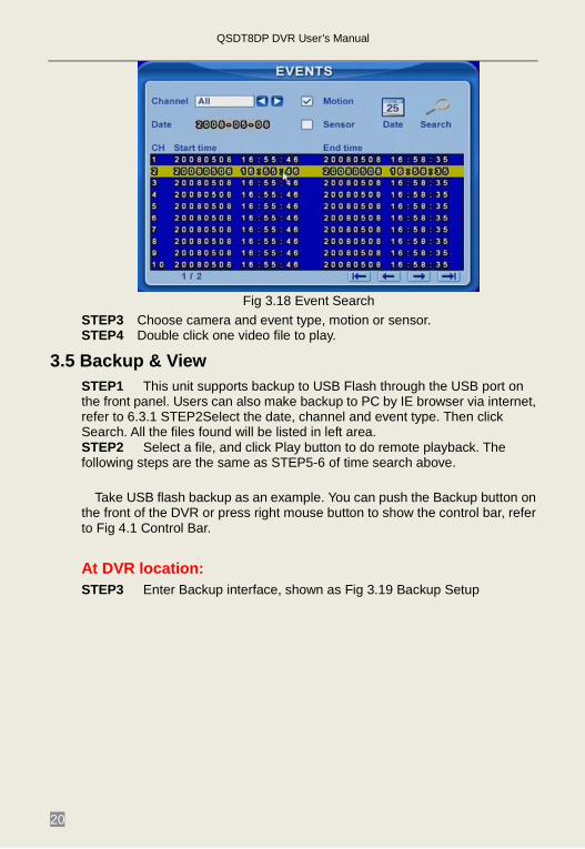
Fig 3.18 Event Search
STEP3 Choose camera and event type, motion or sensor. STEP4 Double click one video file to play.
3.5 Backup & View STEP1 This unit supports backup to USB Flash through the USB port on the front panel. Users can also make backup to PC by IE browser via internet, refer to 6.3.1 STEP2Select the date, channel and event type. Then click Search. All the files found will be listed in left area. STEP2 Select a file, and click Play button to do remote playback. The following steps are the same as STEP5-6 of time search above.
Take USB flash backup as an example. You can push the Backup button on
the front of the DVR or press right mouse button to show the control bar, refer to Fig 4.1 Control Bar.
At DVR location: STEP3 Enter Backup interface, shown as Fig 3.19 Backup Setup
QSDT8DP DVR User’s Manual
21
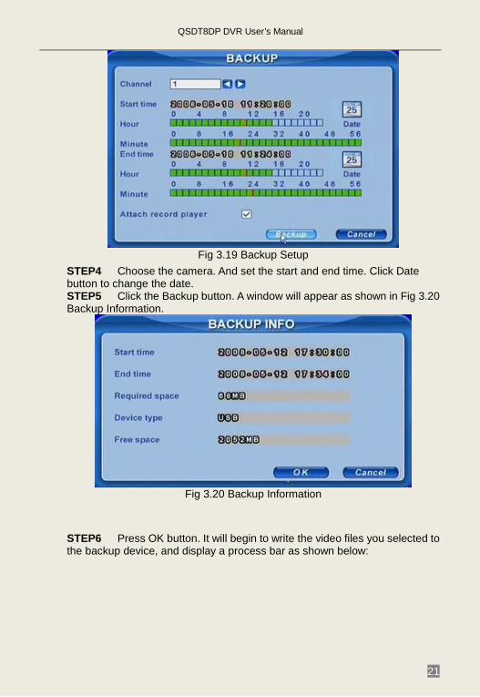
Fig 3.19 Backup Setup
STEP4 Choose the camera. And set the start and end time. Click Date button to change the date. STEP5 Click the Backup button. A window will appear as shown in Fig 3.20 Backup Information.
Fig 3.20 Backup Information
STEP6 Press OK button. It will begin to write the video files you selected to the backup device, and display a process bar as shown below:
QSDT8DP DVR User’s Manual
22
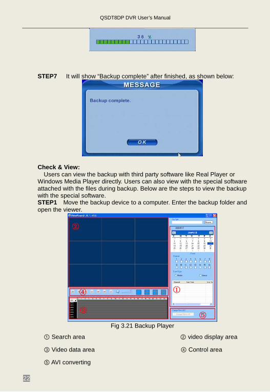
STEP7 It will show “Backup complete” after finished, as shown below:
Check & View:
Users can view the backup with third party software like Real Player or Windows Media Player directly. Users can also view with the special software attached with the files during backup. Below are the steps to view the backup with the special software. STEP1 Move the backup device to a computer. Enter the backup folder and open the viewer.
Fig 3.21 Backup Player
① Search area ② video display area
③ Video data area ④ Control area
⑤ AVI converting
QSDT8DP DVR User’s Manual
23
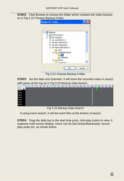
STEP2 Click Browse to choose the folder which contains the video backup, as in Fig 3.22 Choose Backup Folder.
Fig 3.22 Choose Backup Folder
STEP3 Set the date and channels. It will show the recorded video in area③ with green at the top as in Fig 3.23 Backup Data Search.
Fig 3.23 Backup Data Search
If using event search, it will list event files at the bottom of area①
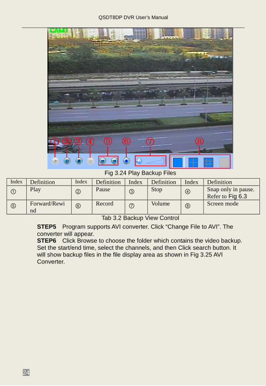
STEP4 Drag the slide bar to the start time point, click play button to view. It supports multi screen display. Users can do fast forward/backward, record, play audio etc, as shown below.
QSDT8DP DVR User’s Manual
24
Fig 3.24 Play Backup Files
Index Definition Index Definition Index Definition Index Definition ① Play ② Pause ③ Stop ④ Snap only in pause.
Refer to Fig 6.3 ⑤ Forward/Rewi
nd ⑥ Record ⑦ Volume ⑧ Screen mode
Tab 3.2 Backup View Control STEP5 Program supports AVI converter. Click “Change File to AVI”. The converter will appear. STEP6 Click Browse to choose the folder which contains the video backup. Set the start/end time, select the channels, and then Click search button. It will show backup files in the file display area as shown in Fig 3.25 AVI Converter.
QSDT8DP DVR User’s Manual
25
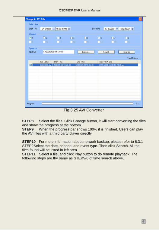
Fig 3.25 AVI Converter
STEP8 Select the files. Click Change button, it will start converting the files and show the progress at the bottom. STEP9 When the progress bar shows 100% it is finished. Users can play the AVI files with a third party player directly. STEP10 For more information about network backup, please refer to 6.3.1 STEP2Select the date, channel and event type. Then click Search. All the files found will be listed in left area. STEP11 Select a file, and click Play button to do remote playback. The following steps are the same as STEP5-6 of time search above.
QSDT8DP DVR User’s Manual
26
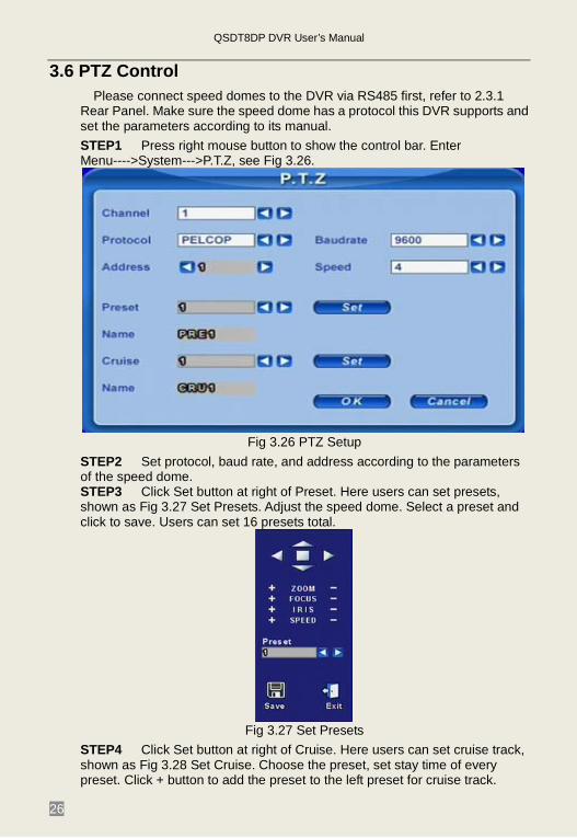
3.6 PTZ Control Please connect speed domes to the DVR via RS485 first, refer to 2.3.1
Rear Panel. Make sure the speed dome has a protocol this DVR supports and set the parameters according to its manual. STEP1 Press right mouse button to show the control bar. Enter Menu---->System--->P.T.Z, see Fig 3.26.
Fig 3.26 PTZ Setup
STEP2 Set protocol, baud rate, and address according to the parameters of the speed dome. STEP3 Click Set button at right of Preset. Here users can set presets, shown as Fig 3.27 Set Presets. Adjust the speed dome. Select a preset and click to save. Users can set 16 presets total.
Fig 3.27 Set Presets
STEP4 Click Set button at right of Cruise. Here users can set cruise track, shown as Fig 3.28 Set Cruise. Choose the preset, set stay time of every preset. Click + button to add the preset to the left preset for cruise track.

QSDT8DP DVR User’s Manual
27
Fig 3.28 Set Cruise
STEP5 Select a preset in left preset list, click – button to delete the preset. Click ↑,↓,↑,↓ to adjust the sequence of the presets in the auto cruise setup. Click Save to save and return to the previous interface. STEP6 Click OK button to save and exit. Press right mouse button to show the control bar. Click PTZ to enter PTZ control, shown as Fig 3.29 PTZ Control.
Fig 3.29 PTZ Control
STEP7 Select the speed dome. Click the direction buttons to move the camera. Click the relative + and – buttons to adjust zoom, focus, IRIS and speed. Click □ button to stop the change. STEP8 Select the preset, the speed dome will go to that point directly. Select Cruise, it will do auto cruise.
QSDT8DP DVR User’s Manual
28
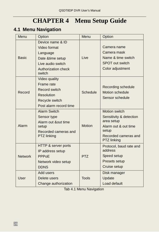
CHAPTER 4 Menu Setup Guide 4.1 Menu Navigation
Menu Option Menu Option
Basic
Device name & ID Video format Language Date &time setup Live audio switch Authorization check switch
Live
Camera name Camera mask Name & time switch SPOT out switch Color adjustment
Record
Video quality Frame rate Record switch Resolution Recycle switch Post alarm record time
Schedule Recording schedule Motion schedule Sensor schedule
Alarm
Alarm Switch Sensor type Alarm out &out time setup Recorded cameras and PTZ linking
Motion
Motion switch Sensitivity & detection area setup Alarm out & out time setup Recorded cameras and PTZ linking
Network
HTTP & server ports IP address setup PPPoE Network video setup DDNS
PTZ
Protocol, baud rate and address Speed setup Presets setup Cruise setup
User Add users Delete users Change authorization
Tools Disk manager Update Load default
Tab 4.1 Menu Navigation
QSDT8DP DVR User’s Manual
29
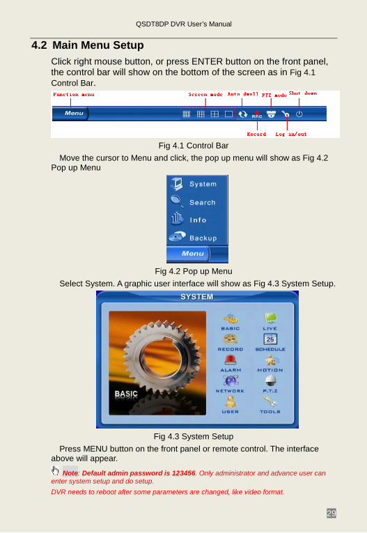
4.2 Main Menu Setup Click right mouse button, or press ENTER button on the front panel, the control bar will show on the bottom of the screen as in Fig 4.1 Control Bar.
Fig 4.1 Control Bar
Move the cursor to Menu and click, the pop up menu will show as Fig 4.2 Pop up Menu
Fig 4.2 Pop up Menu
Select System. A graphic user interface will show as Fig 4.3 System Setup.
Fig 4.3 System Setup
Press MENU button on the front panel or remote control. The interface above will appear.
Note: Default admin password is 123456. Only administrator and advance user can enter system setup and do setup. DVR needs to reboot after some parameters are changed, like video format.
QSDT8DP DVR User’s Manual
30
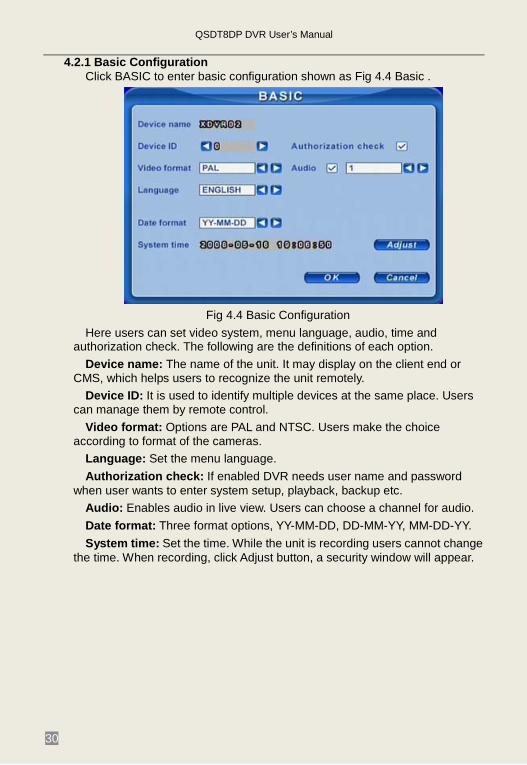
4.2.1 Basic Configuration Click BASIC to enter basic configuration shown as Fig 4.4 Basic .
Fig 4.4 Basic Configuration
Here users can set video system, menu language, audio, time and authorization check. The following are the definitions of each option.
Device name: The name of the unit. It may display on the client end or CMS, which helps users to recognize the unit remotely.
Device ID: It is used to identify multiple devices at the same place. Users can manage them by remote control.
Video format: Options are PAL and NTSC. Users make the choice according to format of the cameras.
Language: Set the menu language. Authorization check: If enabled DVR needs user name and password
when user wants to enter system setup, playback, backup etc. Audio: Enables audio in live view. Users can choose a channel for audio. Date format: Three format options, YY-MM-DD, DD-MM-YY, MM-DD-YY. System time: Set the time. While the unit is recording users cannot change
the time. When recording, click Adjust button, a security window will appear.
QSDT8DP DVR User’s Manual
31
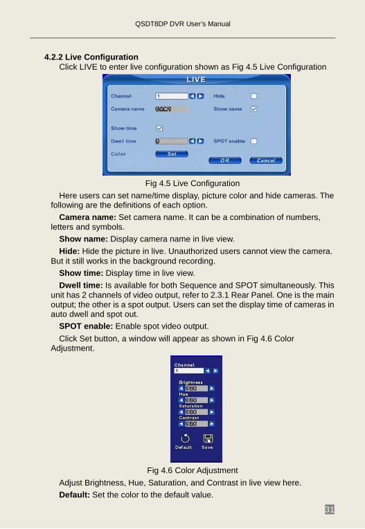
4.2.2 Live Configuration Click LIVE to enter live configuration shown as Fig 4.5 Live Configuration
Fig 4.5 Live Configuration
Here users can set name/time display, picture color and hide cameras. The following are the definitions of each option.
Camera name: Set camera name. It can be a combination of numbers, letters and symbols.
Show name: Display camera name in live view. Hide: Hide the picture in live. Unauthorized users cannot view the camera.
But it still works in the background recording. Show time: Display time in live view. Dwell time: Is available for both Sequence and SPOT simultaneously. This
unit has 2 channels of video output, refer to 2.3.1 Rear Panel. One is the main output; the other is a spot output. Users can set the display time of cameras in auto dwell and spot out.
SPOT enable: Enable spot video output. Click Set button, a window will appear as shown in Fig 4.6 Color
Adjustment.
Fig 4.6 Color Adjustment
Adjust Brightness, Hue, Saturation, and Contrast in live view here. Default: Set the color to the default value.
QSDT8DP DVR User’s Manual
32
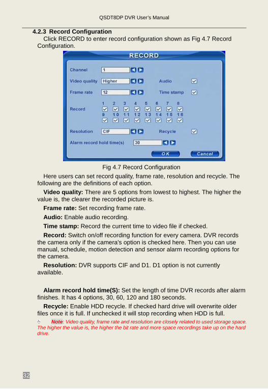
4.2.3 Record Configuration Click RECORD to enter record configuration shown as Fig 4.7 Record
Configuration.
Fig 4.7 Record Configuration
Here users can set record quality, frame rate, resolution and recycle. The following are the definitions of each option.
Video quality: There are 5 options from lowest to highest. The higher the value is, the clearer the recorded picture is.
Frame rate: Set recording frame rate. Audio: Enable audio recording. Time stamp: Record the current time to video file if checked. Record: Switch on/off recording function for every camera. DVR records
the camera only if the camera’s option is checked here. Then you can use manual, schedule, motion detection and sensor alarm recording options for the camera.
Resolution: DVR supports CIF and D1. D1 option is not currently available.
Alarm record hold time(S): Set the length of time DVR records after alarm
finishes. It has 4 options, 30, 60, 120 and 180 seconds. Recycle: Enable HDD recycle. If checked hard drive will overwrite older
files once it is full. If unchecked it will stop recording when HDD is full. Note: Video quality, frame rate and resolution are closely related to used storage space.
The higher the value is, the higher the bit rate and more space recordings take up on the hard drive.
QSDT8DP DVR User’s Manual
33
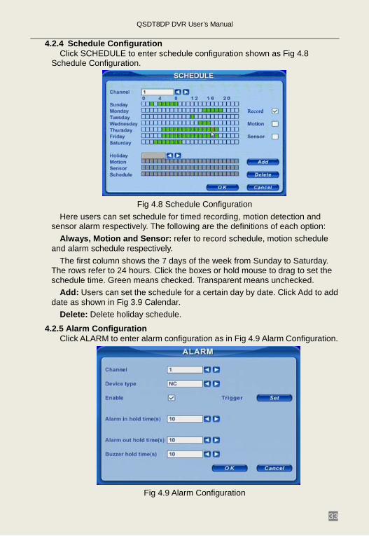
4.2.4 Schedule Configuration Click SCHEDULE to enter schedule configuration shown as Fig 4.8
Schedule Configuration.
Fig 4.8 Schedule Configuration
Here users can set schedule for timed recording, motion detection and sensor alarm respectively. The following are the definitions of each option:
Always, Motion and Sensor: refer to record schedule, motion schedule and alarm schedule respectively.
The first column shows the 7 days of the week from Sunday to Saturday. The rows refer to 24 hours. Click the boxes or hold mouse to drag to set the schedule time. Green means checked. Transparent means unchecked.
Add: Users can set the schedule for a certain day by date. Click Add to add date as shown in Fig 3.9 Calendar.
Delete: Delete holiday schedule.
4.2.5 Alarm Configuration Click ALARM to enter alarm configuration as in Fig 4.9 Alarm Configuration.
Fig 4.9 Alarm Configuration
QSDT8DP DVR User’s Manual
34
Here users can set sensor type, alarm trigger and alarm time. The following are the definitions of each option.
Device type: NC and NO (Normal Close and Normal Open). Set the value according to the alarm signal level of the sensors.
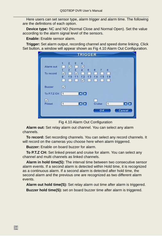
Enable: Enable sensor alarm. Trigger: Set alarm output, recording channel and speed dome linking. Click
Set button, a window will appear shown as Fig 4.10 Alarm Out Configuration.
Fig 4.10 Alarm Out Configuration
Alarm out: Set relay alarm out channel. You can select any alarm channels.
To record: Set recording channels. You can select any record channels. It will record on the cameras you choose here when alarm triggered.
Buzzer: Enable on board buzzer for alarm. To P.T.Z CH: Set linked preset and cruise for alarm. You can select any
channel and multi channels as linked channels. Alarm in hold time(S): The interval time between two consecutive sensor
alarm events. If a second alarm is detected within Hold time, it is recognized as a continuous alarm. If a second alarm is detected after hold time, the second alarm and the previous one are recognized as two different alarm events.
Alarm out hold time(S): Set relay alarm out time after alarm is triggered. Buzzer hold time(S): set on board buzzer time after alarm is triggered.
QSDT8DP DVR User’s Manual
35
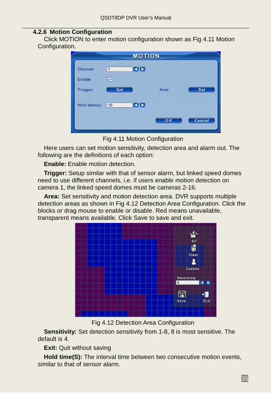
4.2.6 Motion Configuration Click MOTION to enter motion configuration shown as Fig 4.11 Motion
Configuration.
Fig 4.11 Motion Configuration
Here users can set motion sensitivity, detection area and alarm out. The following are the definitions of each option:
Enable: Enable motion detection. Trigger: Setup similar with that of sensor alarm, but linked speed domes
need to use different channels, i.e. if users enable motion detection on camera 1, the linked speed domes must be cameras 2-16.
Area: Set sensitivity and motion detection area. DVR supports multiple detection areas as shown in Fig 4.12 Detection Area Configuration. Click the blocks or drag mouse to enable or disable. Red means unavailable, transparent means available. Click Save to save and exit.
Fig 4.12 Detection Area Configuration
Sensitivity: Set detection sensitivity from 1-8, 8 is most sensitive. The default is 4.
Exit: Quit without saving Hold time(S): The interval time between two consecutive motion events,
similar to that of sensor alarm.
QSDT8DP DVR User’s Manual
36
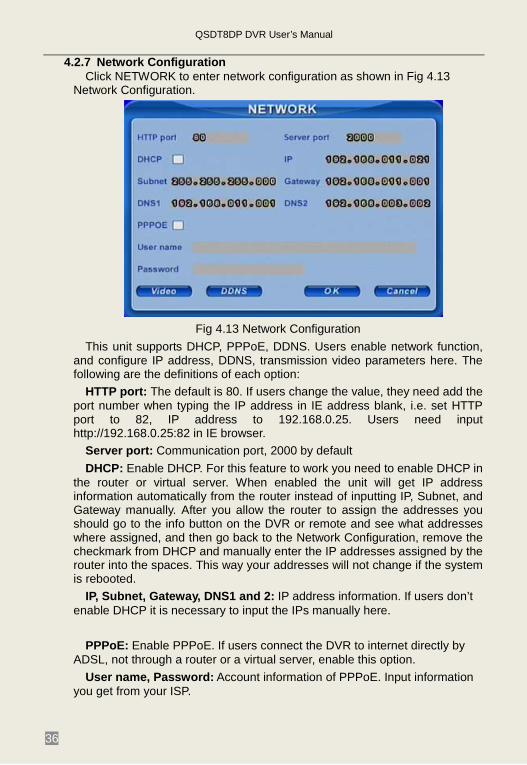
4.2.7 Network Configuration Click NETWORK to enter network configuration as shown in Fig 4.13
Network Configuration.
Fig 4.13 Network Configuration
This unit supports DHCP, PPPoE, DDNS. Users enable network function, and configure IP address, DDNS, transmission video parameters here. The following are the definitions of each option:
HTTP port: The default is 80. If users change the value, they need add the port number when typing the IP address in IE address blank, i.e. set HTTP port to 82, IP address to 192.168.0.25. Users need input http://192.168.0.25:82 in IE browser.
Server port: Communication port, 2000 by default DHCP: Enable DHCP. For this feature to work you need to enable DHCP in
the router or virtual server. When enabled the unit will get IP address information automatically from the router instead of inputting IP, Subnet, and Gateway manually. After you allow the router to assign the addresses you should go to the info button on the DVR or remote and see what addresses where assigned, and then go back to the Network Configuration, remove the checkmark from DHCP and manually enter the IP addresses assigned by the router into the spaces. This way your addresses will not change if the system is rebooted.
IP, Subnet, Gateway, DNS1 and 2: IP address information. If users don’t enable DHCP it is necessary to input the IPs manually here.
PPPoE: Enable PPPoE. If users connect the DVR to internet directly by
ADSL, not through a router or a virtual server, enable this option. User name, Password: Account information of PPPoE. Input information
you get from your ISP.
QSDT8DP DVR User’s Manual
37
DDNS: Click DDNS, a window will appear as shown in Fig 4.14 DDNS Configuration. DVR supports DYNDNS and MYQ-SEE. Users need register at www.dyndns.com or myq-see.com. Then input registered ID and password here. Click OK button. The unit will connect Through DYNDNS or MYQ-SEE.
Fig 4.14 DDNS Configuration
Server: Select DDNS server. User name and Password: Input registered information from DDNS
provider. This unit supports dual stream. Users can set picture quality, frame rate and
resolution separately for network, according to the network bandwidth. Click Video to enter the configuration interface shown as Fig 4.15 Network Video Configuration.
Fig 4.15 Network Video Configuration
Video quality: Network picture quality. Frame rate: There are two options, 1 and 3 fps. Resolution: Currently only has CIF available. Time stamp: Display time in remote preview.
QSDT8DP DVR User’s Manual
38
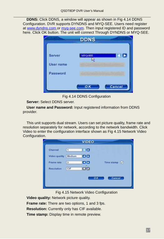
4.2.8 P.T.Z Configuration Click P.T.Z to enter PTZ configuration shown as Fig 4.16 PTZ
Configuration.
Fig 4.16 PTZ Configuration
Here users can set protocol, baud rate, address, presets and auto cruise track. The following are the definitions of each option:
Protocol, Baud rate, Address: Set the value according to the settings of the speed dome.
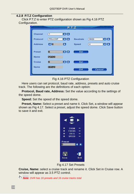
Speed: Set the speed of the speed dome. Preset, Name: Select a preset and name it. Click Set, a window will appear
shown as Fig 4.17. Select a preset, adjust the speed dome. Click Save button to save it and exit.
Fig 4.17 Set Presets
Cruise, Name: select a cruise track and rename it. Click Set in Cruise row. A window will appear as 3.5 PTZ control.
Note: DVR has 16 presets and 16 cruise tracks total
QSDT8DP DVR User’s Manual
39
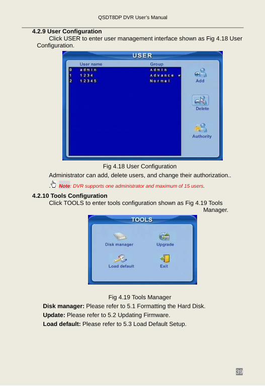
4.2.9 User Configuration Click USER to enter user management interface shown as Fig 4.18 User
Configuration.
Fig 4.18 User Configuration
Administrator can add, delete users, and change their authorization..
. Note: DVR supports one administrator and maximum of 15 users.
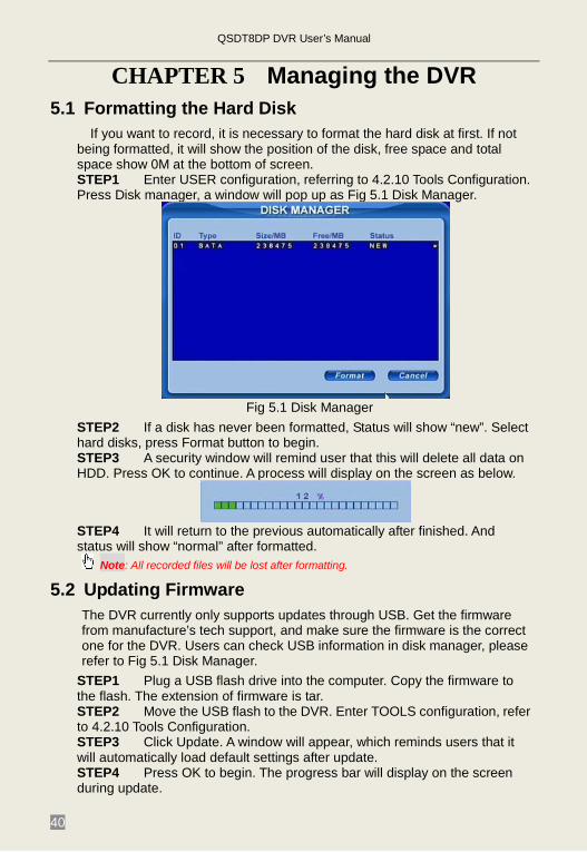
4.2.10 Tools Configuration Click TOOLS to enter tools configuration shown as Fig 4.19 Tools
Manager.
Fig 4.19 Tools Manager
Disk manager: Please refer to 5.1 Formatting the Hard Disk. Update: Please refer to 5.2 Updating Firmware.
Load default: Please refer to 5.3 Load Default Setup.
QSDT8DP DVR User’s Manual
40
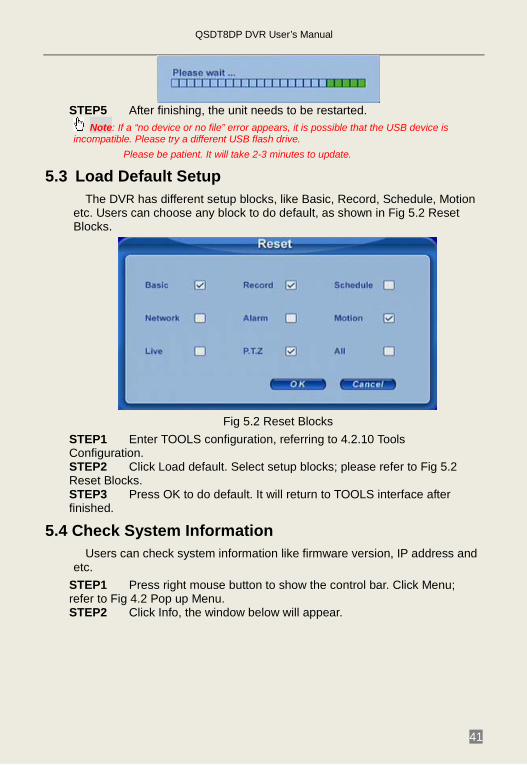
CHAPTER 5 Managing the DVR 5.1 Formatting the Hard Disk
If you want to record, it is necessary to format the hard disk at first. If not being formatted, it will show the position of the disk, free space and total space show 0M at the bottom of screen. STEP1 Enter USER configuration, referring to 4.2.10 Tools Configuration. Press Disk manager, a window will pop up as Fig 5.1 Disk Manager.
Fig 5.1 Disk Manager
STEP2 If a disk has never been formatted, Status will show “new”. Select hard disks, press Format button to begin. STEP3 A security window will remind user that this will delete all data on HDD. Press OK to continue. A process will display on the screen as below.
STEP4 It will return to the previous automatically after finished. And status will show “normal” after formatted.
Note: All recorded files will be lost after formatting.
5.2 Updating Firmware The DVR currently only supports updates through USB. Get the firmware from manufacture’s tech support, and make sure the firmware is the correct one for the DVR. Users can check USB information in disk manager, please refer to Fig 5.1 Disk Manager.
STEP1 Plug a USB flash drive into the computer. Copy the firmware to the flash. The extension of firmware is tar. STEP2 Move the USB flash to the DVR. Enter TOOLS configuration, refer to 4.2.10 Tools Configuration. STEP3 Click Update. A window will appear, which reminds users that it will automatically load default settings after update. STEP4 Press OK to begin. The progress bar will display on the screen during update.
QSDT8DP DVR User’s Manual
41
STEP5 After finishing, the unit needs to be restarted.
Note: If a “no device or no file” error appears, it is possible that the USB device is incompatible. Please try a different USB flash drive. Please be patient. It will take 2-3 minutes to update.
5.3 Load Default Setup The DVR has different setup blocks, like Basic, Record, Schedule, Motion
etc. Users can choose any block to do default, as shown in Fig 5.2 Reset Blocks.
Fig 5.2 Reset Blocks
STEP1 Enter TOOLS configuration, referring to 4.2.10 Tools Configuration. STEP2 Click Load default. Select setup blocks; please refer to Fig 5.2 Reset Blocks. STEP3 Press OK to do default. It will return to TOOLS interface after finished.
5.4 Check System Information Users can check system information like firmware version, IP address and
etc. STEP1 Press right mouse button to show the control bar. Click Menu; refer to Fig 4.2 Pop up Menu. STEP2 Click Info, the window below will appear.
QSDT8DP DVR User’s Manual
42
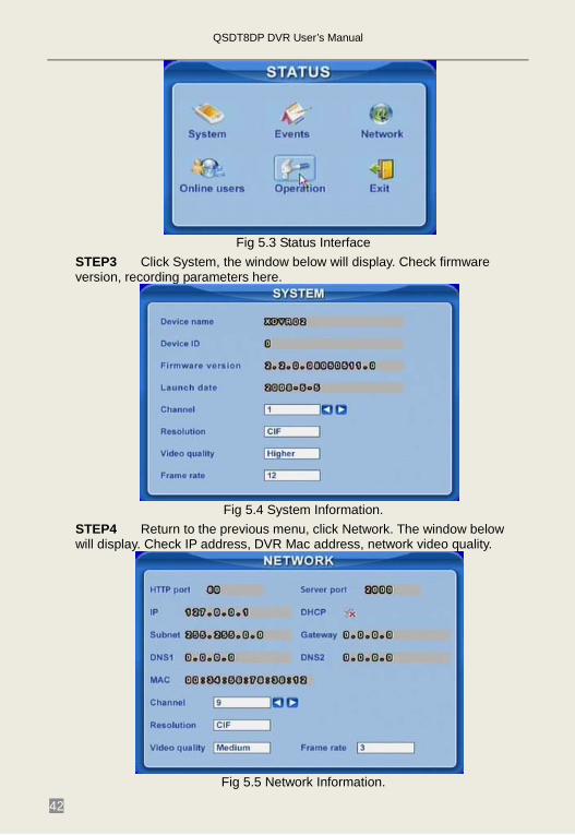
Fig 5.3 Status Interface
STEP3 Click System, the window below will display. Check firmware version, recording parameters here.
Fig 5.4 System Information.
STEP4 Return to the previous menu, click Network. The window below will display. Check IP address, DVR Mac address, network video quality.
Fig 5.5 Network Information.
QSDT8DP DVR User’s Manual
43
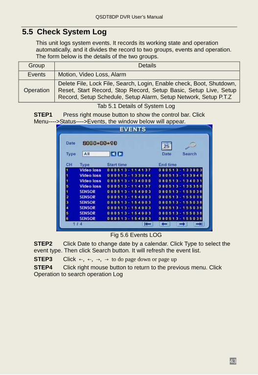
5.5 Check System Log This unit logs system events. It records its working state and operation automatically, and it divides the record to two groups, events and operation. The form below is the details of the two groups.
Group Details Events Motion, Video Loss, Alarm
Operation Delete File, Lock File, Search, Login, Enable check, Boot, Shutdown, Reset, Start Record, Stop Record, Setup Basic, Setup Live, Setup Record, Setup Schedule, Setup Alarm, Setup Network, Setup P.T.Z
Tab 5.1 Details of System Log STEP1 Press right mouse button to show the control bar. Click Menu---->Status---->Events, the window below will appear.
Fig 5.6 Events LOG
STEP2 Click Date to change date by a calendar. Click Type to select the event type. Then click Search button. It will refresh the event list. STEP3 Click ←, ←, →, → to do page down or page up STEP4 Click right mouse button to return to the previous menu. Click Operation to search operation Log
QSDT8DP DVR User’s Manual
44
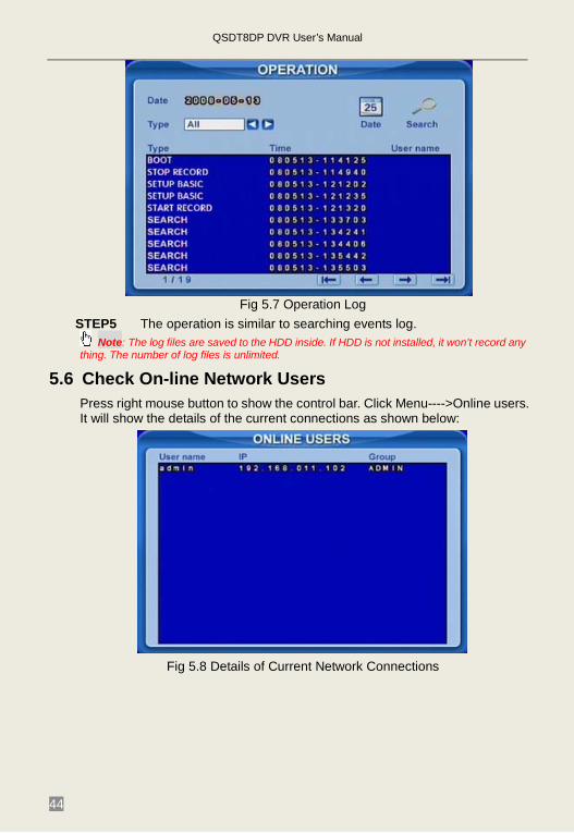
Fig 5.7 Operation Log
STEP5 The operation is similar to searching events log. Note: The log files are saved to the HDD inside. If HDD is not installed, it won’t record any
thing. The number of log files is unlimited.
5.6 Check On-line Network Users Press right mouse button to show the control bar. Click Menu---->Online users. It will show the details of the current connections as shown below:
Fig 5.8 Details of Current Network Connections
QSDT8DP DVR User’s Manual
45
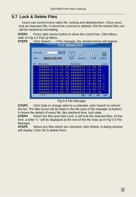
5.7 Lock & Delete Files Users can control every video file, locking and deleting them. Once users
lock an important file, it cannot be covered or deleted. But the locked files can still be cleared by formatting.
STEP1 Press right mouse button to show the control bar. Click Menu, refer to Fig 4.2 Pop up Menu. STEP2 Click Search----->File manager, the window below will appear.
Fig 5.9 File Manager
STEP3 Click Date to change date by a calendar, click Search to refresh the list. The files found will be listed in the file area of file manager at bottom. It shows the details of every file, like start/end time, lock state. STEP4 Select the files and click Lock, it will lock the selected files. At this time, a letter “L” will be displayed at the end of the file rows as in Fig 5.9 File Manager. STEP5 Select any files which are unlocked, click Delete. A dialog window will display. Click Ok to delete them.
QSDT8DP DVR User’s Manual
46
CHAPTER 6 Remote Surveillance 6.1 Accessing the DVR
If you want to view the DVR remotely it must be connect to a LAN or internet, and network server must be enabled in the unit. Please refer to 4.2.7 Network Configuration.
This unit supports Internet Explorer browser without any client software installed, it supports XP and Vista operating systems.
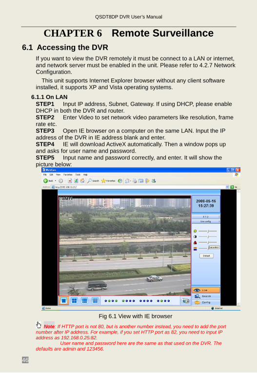
6.1.1 On LAN STEP1 Input IP address, Subnet, Gateway. If using DHCP, please enable DHCP in both the DVR and router. STEP2 Enter Video to set network video parameters like resolution, frame rate etc. STEP3 Open IE browser on a computer on the same LAN. Input the IP address of the DVR in IE address blank and enter. STEP4 IE will download ActiveX automatically. Then a window pops up and asks for user name and password. STEP5 Input name and password correctly, and enter. It will show the picture below:
Fig 6.1 View with IE browser
Note: If HTTP port is not 80, but is another number instead, you need to add the port number after IP address. For example, if you set HTTP port as 82, you need to input IP address as 192.168.0.25:82.
User name and password here are the same as that used on the DVR. The defaults are admin and 123456.
QSDT8DP DVR User’s Manual
47
6.1.2 On WAN There are two ways that the DVR can be connected to the internet. 1. Connect the DVR to internet through a router or virtual server. STEP1 Input IP address, Subnet, Gateway. You can get the Subnet and Gateway by going to the run option on a computer that is attached to the same router as the DVR and typing “cmd” or in the run box and clicking ok. This will open a dialog box. At the command prompt type “ipconfig”. This will show you the Gateway, which is the network IP address of the router, and the Subnet. Enter these numbers into the network settings of the DVR. The IP address of the DVR needs to have the same first 3 sets of numbers as the Gateway, but a 4th set of numbers that is different then any other device attached to the router. If using DHCP, please enable DHCP in both the DVR and router. STEP2 Enter Video to set network video parameters like resolution, frame rate etc. STEP3 Forward port numbers 80 and 2000 in Virtual Server setup of the router or virtual server to the IP address of the DVR.
Note: The procedure to forward ports is different in different routers and servers please check your router manual. You can also find instructions on forwarding ports on most popular routers at www.portforward.com. STEP4 If you want to utilize dynamic domain name, you need to apply for a domain name in a DNS server supported by the DVR or router. Then add to the DVR or router. Currently this unit only supports www.dyndns.com or myq-see.com. To set up the router, please check the router manual. STEP5 Open IE browser, input IP address or dynamic domain name and enter. If HTTP port is not 80, add the port number after IP address or domain name. Note: If you are accessing the DVR from a computer that is attached to the same router as the DVR you need to enter the IP address of the DVR, if you are accessing the DVR from a remote computer you need to enter the internet IP of the router. You can get this address by going to a website such as www.myipaddress.com from a computer that is attached to the same router as the DVR. STEP6 IE will download ActiveX automatically. Then a window pops up and asks for user name and password. STEP7 Input name and password correctly, and enter to view.
Note: If you cannot download and install ActiveX, please refer to Appendix A FAQ Q7. 2. Connect the DVR to internet directly. STEP1 Input IP address, Subnet, Gateway gotten from your ISP. If using ADSL, please input user name and password, and click OK. The DVR will connect to the server and show “connection succeeds”. STEP2 The following steps are the same as STEP4-7 of the connection way above.
QSDT8DP DVR User’s Manual
48
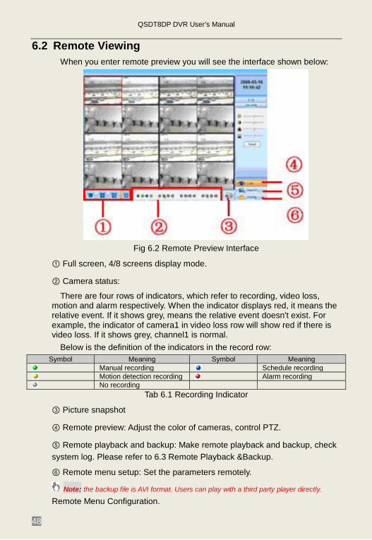
6.2 Remote Viewing When you enter remote preview you will see the interface shown below:
Fig 6.2 Remote Preview Interface
① Full screen, 4/8 screens display mode.
② Camera status:
There are four rows of indicators, which refer to recording, video loss, motion and alarm respectively. When the indicator displays red, it means the relative event. If it shows grey, means the relative event doesn't exist. For example, the indicator of camera1 in video loss row will show red if there is video loss. If it shows grey, channel1 is normal.
Below is the definition of the indicators in the record row: Symbol Meaning Symbol Meaning
Manual recording Schedule recording Motion detection recording Alarm recording No recording
Tab 6.1 Recording Indicator
③ Picture snapshot
④ Remote preview: Adjust the color of cameras, control PTZ.
⑤ Remote playback and backup: Make remote playback and backup, check system log. Please refer to 6.3 Remote Playback &Backup.
⑥ Remote menu setup: Set the parameters remotely.
Note: the backup file is AVI format. Users can play with a third party player directly.
Remote Menu Configuration.
QSDT8DP DVR User’s Manual
49
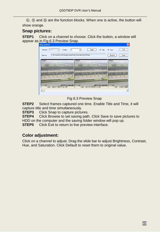
④, ⑤ and ⑥ are the function blocks. When one is active, the button will show orange. Snap pictures: STEP1 Click on a channel to choose. Click the button, a window will appear as in Fig 6.3 Preview Snap.
Fig 6.3 Preview Snap
STEP2 Select frames captured one time. Enable Title and Time, it will capture title and time simultaneously. STEP3 Click Snap to capture pictures. STEP4 Click Browse to set saving path. Click Save to save pictures to HDD on the computer and the saving folder window will pop up. STEP5 Click Exit to return to live preview interface. Color adjustment: Click on a channel to adjust. Drag the slide bar to adjust Brightness, Contrast, Hue, and Saturation. Click Default to reset them to original value.
QSDT8DP DVR User’s Manual
50
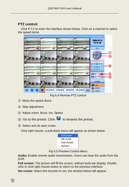
PTZ control: Click P.T.Z to enter the interface shown below. Click on a channel to select
the speed dome.
Fig 6.4 Remote PTZ control
① Move the speed dome.
② Stop adjustment.
③ Adjust zoom, focus, Iris, Speed.
④ Go to the preset. Click to rename the preset.
⑤ Select and do auto cruise.
Click right mouse, a pull-down menu will appear as shown below.
Fig 6.5 Preview Control Menu
Audio: Enable remote audio transmission. Users can hear the audio from the DVR. Full screen: The picture will fill the screen, without tools bar display. Double click or click right mouse button to return to the previous interface. Set cruise: Select this function to set, the window below will appear:
QSDT8DP DVR User’s Manual
51
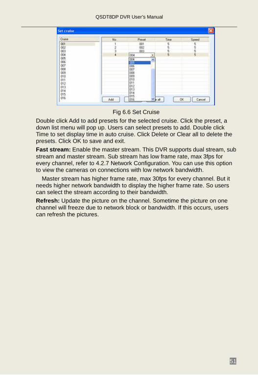
Fig 6.6 Set Cruise
Double click Add to add presets for the selected cruise. Click the preset, a down list menu will pop up. Users can select presets to add. Double click Time to set display time in auto cruise. Click Delete or Clear all to delete the presets. Click OK to save and exit. Fast stream: Enable the master stream. This DVR supports dual stream, sub stream and master stream. Sub stream has low frame rate, max 3fps for every channel, refer to 4.2.7 Network Configuration. You can use this option to view the cameras on connections with low network bandwidth.
Master stream has higher frame rate, max 30fps for every channel. But it needs higher network bandwidth to display the higher frame rate. So users can select the stream according to their bandwidth. Refresh: Update the picture on the channel. Sometime the picture on one channel will freeze due to network block or bandwidth. If this occurs, users can refresh the pictures.
QSDT8DP DVR User’s Manual
52
6.3 Remote Playback &Backup 6.3.1 Remote Playback
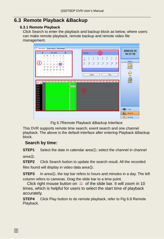
Click Search to enter the playback and backup block as below, where users can make remote playback, remote backup and remote video file management.
Fig 6.7Remote Playback &Backup Interface
This DVR supports remote time search, event search and one channel playback. The above is the default interface after entering Playback &Backup block. Search by time:
STEP1 Select the date in calendar area①; select the channel in channel
area②. STEP2 Click Search button to update the search result. All the recorded files found will display in video data area③.
STEP3 In area③, the top bar refers to hours and minutes in a day. The left column refers to cameras. Drag the slide bar to a time point.
Click right mouse button on of the slide bar. It will zoom in 10 times, which is helpful for users to select the start time of playback accurately. STEP4 Click Play button to do remote playback, refer to Fig 6.8 Remote Playback.
QSDT8DP DVR User’s Manual
53
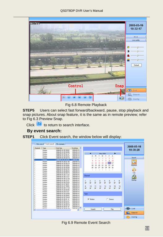
Fig 6.8 Remote Playback
STEP5 Users can select fast forward/backward, pause, stop playback and snap pictures. About snap feature, it is the same as in remote preview; refer to Fig 6.3 Preview Snap.
Click to return to search interface. By event search:
STEP1 Click Event search, the window below will display:
Fig 6.9 Remote Event Search

QSDT8DP DVR User’s Manual
54
STEP2 Select the date, channel and event type. Then click Search. All the files found will be listed in left area. STEP3 Select a file, and click Play button to do remote playback. The following steps are the same as STEP5-6 of time search above.
6.3.2 Remote Backup Users can download the recorded files from the DVR through a network.
Click Backup to enter the interface shown below:
Fig 6.10 Remote Backup Interface STEP1 Select the date and channel. Then click Search button. It will list all the files recorded in the day in left area. STEP2 Click Browse button. Set the saving path. STEP3 Select files in left file area. Holding shift button, you can select multiple files with the mouse simultaneously. STEP4 Click Backup to do remote backup. It will show the progress on the bottom of the screen as below:
Note: the backup file is AVI format. Users can play with a third party player directly.
QSDT8DP DVR User’s Manual
55
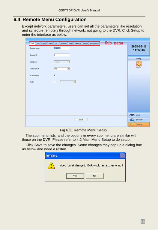
6.4 Remote Menu Configuration Except network parameters, users can set all the parameters like resolution and schedule remotely through network, not going to the DVR. Click Setup to enter the interface as below:
Fig 6.11 Remote Menu Setup
The sub menu lists, and the options in every sub menu are similar with those on the DVR. Please refer to 4.2 Main Menu Setup to do setup.
Click Save to save the changes. Some changes may pop up a dialog box as below and need a restart.

QSDT8DP DVR User’s Manual
56
6.5 Remote DVR Management 6.5.1 Check System Log Remotely
Users can check system log remotely. For the details of system log, please refer to Tab 5.1 Details of System Log.
STEP1 Click Search---->Log, the window below will appear. Event log search is the default interface.
Fig 6.12 Remote System LOG Search
STEP2 Select the date, channel and event type. Then click Search. STEP3 The entire log found will be listed in left area. STEP4 Click Operation to enter operation Log search interface
Fig 6.13 Remote Operation Log Search
QSDT8DP DVR User’s Manual
57
STEP5 Select the date and click Search. It will list all the log files in the day in left area.
6.5.2 Lock & Delete Files Remotely Users can lock and delete video files through network.
STEP1 Click Search---->Playback---->File manager, the window below will appear:
Fig 6.14 Remote File manager
STEP2 Select the date and channels, click Search. All the files found will be listed in the day in left area. STEP3 The relative status will show “Lock” if the file is locked. “Writing” means the file is still in being written. STEP4 Select the files which is unlocked, click Delete. A security window will display to remind users. Click Ok to delete them.
Notice: In all calendar search areas above, the date will be highlighted if there is data recorded.
QSDT8DP DVR User’s Manual
58
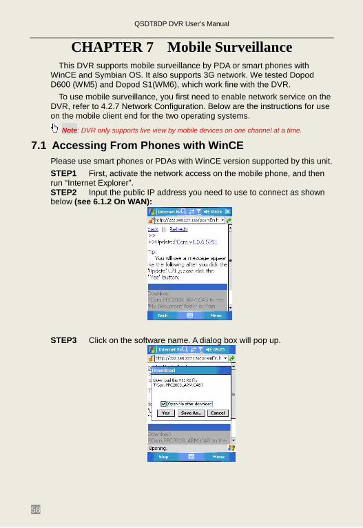
CHAPTER 7 Mobile Surveillance This DVR supports mobile surveillance by PDA or smart phones with
WinCE and Symbian OS. It also supports 3G network. We tested Dopod D600 (WM5) and Dopod S1(WM6), which work fine with the DVR.
To use mobile surveillance, you first need to enable network service on the DVR, refer to 4.2.7 Network Configuration. Below are the instructions for use on the mobile client end for the two operating systems.
Note: DVR only supports live view by mobile devices on one channel at a time.
7.1 Accessing From Phones with WinCE Please use smart phones or PDAs with WinCE version supported by this unit. STEP1 First, activate the network access on the mobile phone, and then run “Internet Explorer”. STEP2 Input the public IP address you need to use to connect as shown below (see 6.1.2 On WAN):
STEP3 Click on the software name. A dialog box will pop up.
QSDT8DP DVR User’s Manual
59
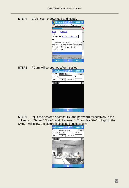
STEP4 Click “Yes” to download and install.
STEP5 PCam will be opened after installed.
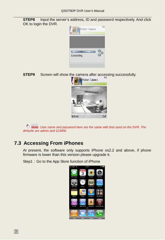
STEP6 Input the server’s address, ID, and password respectively in the columns of “Server”, “User”, and “Password”. Then click “Go” to login to the DVR. It will show the picture if accessed successfully.
QSDT8DP DVR User’s Manual
60
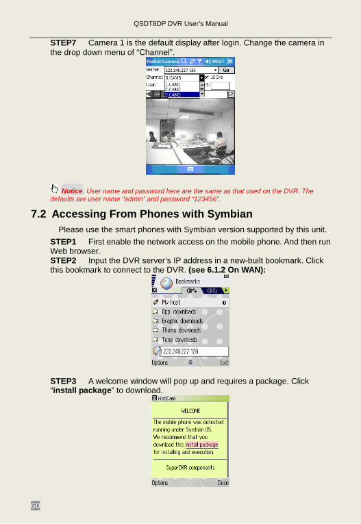
STEP7 Camera 1 is the default display after login. Change the camera in the drop down menu of “Channel”.
Notice: User name and password here are the same as that used on the DVR. The defaults are user name “admin” and password “123456”.
7.2 Accessing From Phones with Symbian Please use the smart phones with Symbian version supported by this unit.
STEP1 First enable the network access on the mobile phone. And then run Web browser. STEP2 Input the DVR server’s IP address in a new-built bookmark. Click this bookmark to connect to the DVR. (see 6.1.2 On WAN):
STEP3 A welcome window will pop up and requires a package. Click “install package” to download.

QSDT8DP DVR User’s Manual
61
STEP4 The security windows will pop up after downloading and ask if OK to install the package. Click YES to install.
STEP5 A Scam shortcut icon appears on the system menu after finish.
STEP6 Run Scam program.
STEP7 Click Options--->Settings to enter login interface.
QSDT8DP DVR User’s Manual
62
STEP8 Input the server’s address, ID and password respectively. And click OK to login the DVR.
STEP9 Screen will show the camera after accessing successfully.
Note: User name and password here are the same with that used on the DVR. The defaults are admin and 123456.
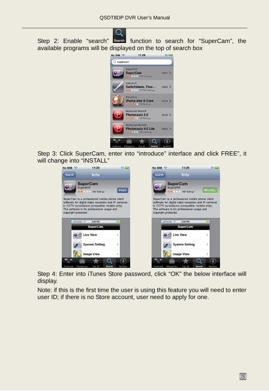
7.3 Accessing From iPhones At present, the software only supports iPhone os2.2 and above, if phone firmware is lower than this version please upgrade it.
Step1:Go to the App Store function of iPhone
QSDT8DP DVR User’s Manual
63
Step 2: Enable “search” function to search for “SuperCam”, the available programs will be displayed on the top of search box
Step 3: Click SuperCam, enter into “introduce” interface and click FREE”, it will change into “INSTALL”
Step 4: Enter into iTunes Store password, click “OK” the below interface will display. Note: if this is the first time the user is using this feature you will need to enter user ID; if there is no Store account, user need to apply for one.
QSDT8DP DVR User’s Manual
64
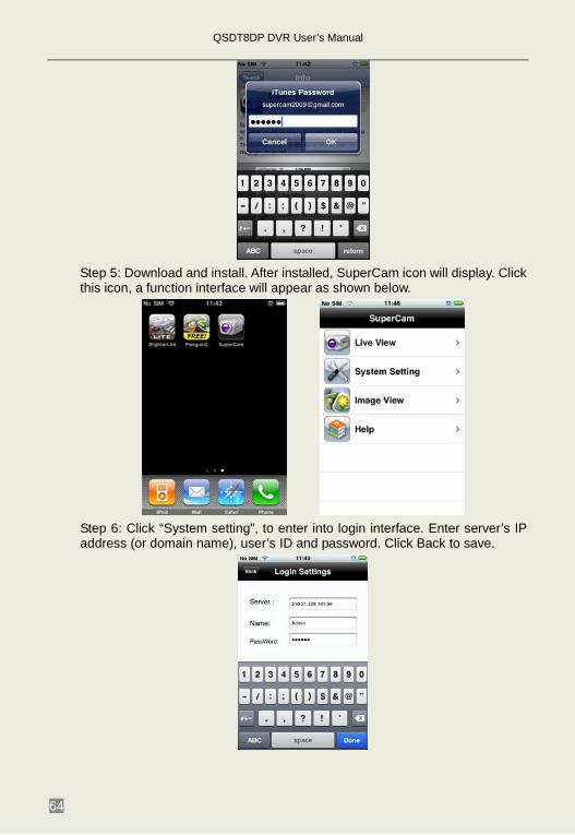
Step 5: Download and install. After installed, SuperCam icon will display. Click this icon, a function interface will appear as shown below.
Step 6: Click “System setting”, to enter into login interface. Enter server’s IP address (or domain name), user’s ID and password. Click Back to save.

QSDT8DP DVR User’s Manual
65
Step 7: Click Live View, the default Cam1 picture will be displayed. Click
to capture picture. Click to enter PTZ mode.
Step 8: On function interface, click Image View to view the captured picture.
Click or to switch to next or previous picture. Click to delete the current picture.
Iphone help
Pic1 Pic2 Pic3 Pic4
QSDT8DP DVR User’s Manual
66
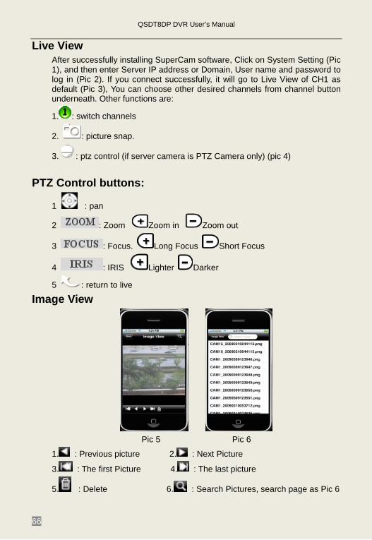
Live View After successfully installing SuperCam software, Click on System Setting (Pic 1), and then enter Server IP address or Domain, User name and password to log in (Pic 2). If you connect successfully, it will go to Live View of CH1 as default (Pic 3), You can choose other desired channels from channel button underneath. Other functions are:
1. : switch channels
2. : picture snap.
3. : ptz control (if server camera is PTZ Camera only) (pic 4)
PTZ Control buttons:
1 : pan
2 : Zoom Zoom in Zoom out
3 : Focus. Long Focus Short Focus
4 : IRIS Lighter Darker
5 : return to live
Image View
Pic 5 Pic 6
1. : Previous picture 2. : Next Picture
3. : The first Picture 4. : The last picture
5. : Delete 6. : Search Pictures, search page as Pic 6

QSDT8DP DVR User’s Manual
67
Appendix A FAQs Q1. The DVR does not start after connecting the power, what is wrong? a. The power adapter may have been damaged, or is not providing enough power. Please change the adapter b. The DVR may not be getting enough power from the outlet or surge protector it is attached to. c. There could be a problem with the system board on the DVR Q2. The indicator lights of the DVR are on, but no output. Why? a. The power adapter may have been damaged, or is not providing enough power. Please change the adapter b. The video format of the DVR is different from that of the monitor. c. Connection problem. Please check the cable and the ports of the monitor and DVR. Q3. Why are no images displayed on some or all of the channels of the DVR? a. Connection problem. Please check the cables and the ports of camera and DVR. b. Camera problem. Please check the cameras by attaching them directly to TV or working port on DVR. c. The video format (NTSC/PAL) of the DVR is different from that of the cameras. Please change DVR video format. Q4. Cannot find HDD a. The power adapter is not providing enough power, or the adapter is not getting enough power from the outlet b. Connection problem. Please check the power and data cables on the HDD. c. The HDD is damaged. Try a new one. Q5. I can not record, what could be the problem? a. HDD is not formatted. Please format it manually first. b. The record function is not enabled or setup correctly. Please refer to 3.3 Recording. c. HDD is full and recycle function is not enabled. Please refer to 4.2.3 Record Configuration. d. The HDD is damaged. Try a new one.
QSDT8DP DVR User’s Manual
68
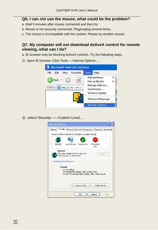
Q6. I can not use the mouse, what could be the problem? a. Wait 5 minutes after mouse connected and then try. b. Mouse is not securely connected. Plug/unplug several times. c. The mouse is incompatible with the system. Please try another mouse. Q7. My computer will not download ActiveX control for remote viewing, what can I do? a. IE browser may be blocking ActiveX controls. Try the following steps:
① Open IE browser. Click Tools-----Internet Options….
② select Security------Custom Level….
QSDT8DP DVR User’s Manual
69
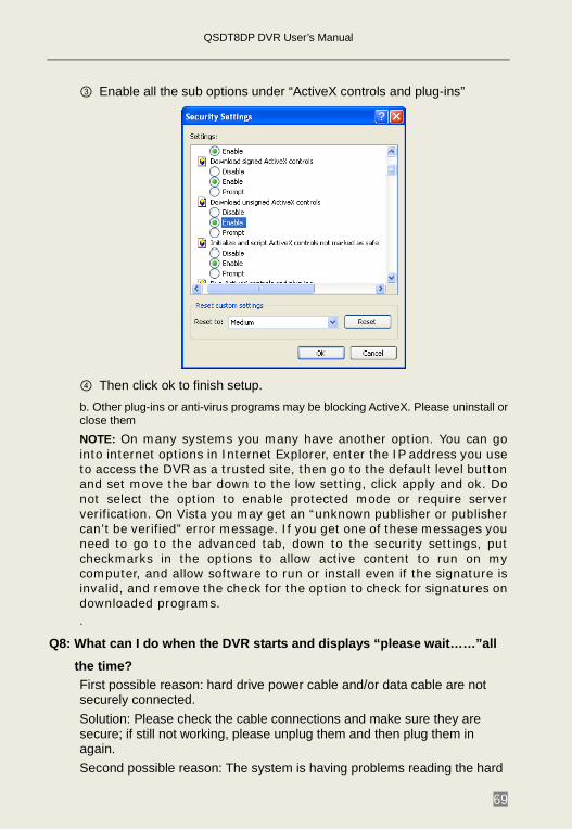
③ Enable all the sub options under “ActiveX controls and plug-ins”
④ Then click ok to finish setup. b. Other plug-ins or anti-virus programs may be blocking ActiveX. Please uninstall or close them NOTE: On many systems you many have another option. You can go into internet options in Internet Explorer, enter the IP address you use to access the DVR as a trusted site, then go to the default level button and set move the bar down to the low setting, click apply and ok. Do not select the option to enable protected mode or require server verification. On Vista you may get an “unknown publisher or publisher can’t be verified” error message. If you get one of these messages you need to go to the advanced tab, down to the security settings, put checkmarks in the options to allow active content to run on my computer, and allow software to run or install even if the signature is invalid, and remove the check for the option to check for signatures on downloaded programs. .
Q8: What can I do when the DVR starts and displays “please wait……”all
the time? First possible reason: hard drive power cable and/or data cable are not securely connected. Solution: Please check the cable connections and make sure they are secure; if still not working, please unplug them and then plug them in again. Second possible reason: The system is having problems reading the hard
QSDT8DP DVR User’s Manual
70
drive. Solution: Try reformatting the current drive or re-placing it.
Q9: Why isn’t the mouse I have plugged into the front USB port working? The front USB port is only for backup to USB flash drive, and does not support a USB mouse. Please use the USB port on the rear panel if using a mouse.
Q10: How do I input password and digital numbers? To input password and digital numbers click the box behind password or items where you need to input numbers, and then a small keyboard will appear. Please select number or letter to input (the default password is 123456), or you can use the digital keys on the front panel, or the digital keys on the remote control.
Q11: How do I upgrade the firmware on the DVR? After you download the new firmware from the Q-See website at www.q-see.com, copy it onto a USB flash drive, and then select “upgrade” in the menu. If upgrading the kernel procedure, please refer to the following method: firstly insert U disk into DVR, and then input “adwsws” in the password of system login and the system will upgrade kernel procedure automatically. After finished, please restart DVR to achieve. Notice: Do not power off the system during the upgrade process! Otherwise, it may damage the chipset and prevent the DVR from starting.
QSDT8DP DVR User’s Manual
71
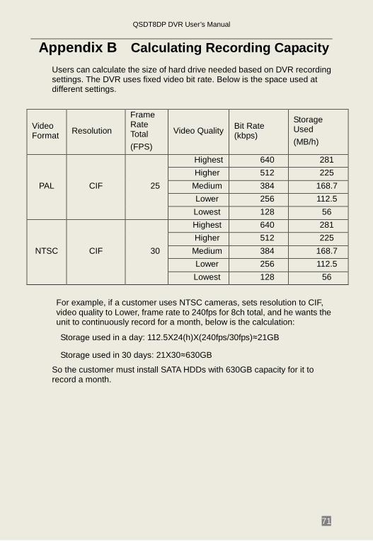
Appendix B Calculating Recording Capacity Users can calculate the size of hard drive needed based on DVR recording settings. The DVR uses fixed video bit rate. Below is the space used at different settings.
Video Format Resolution
Frame Rate Total (FPS)
Video Quality Bit Rate (kbps)
Storage Used (MB/h)
PAL CIF 25
Highest 640 281 Higher 512 225
Medium 384 168.7 Lower 256 112.5 Lowest 128 56
NTSC CIF 30
Highest 640 281 Higher 512 225
Medium 384 168.7 Lower 256 112.5 Lowest 128 56
For example, if a customer uses NTSC cameras, sets resolution to CIF, video quality to Lower, frame rate to 240fps for 8ch total, and he wants the unit to continuously record for a month, below is the calculation:
Storage used in a day: 112.5X24(h)X(240fps/30fps)≈21GB
Storage used in 30 days: 21X30≈630GB
So the customer must install SATA HDDs with 630GB capacity for it to record a month.

QSDT8DP DVR User’s Manual
72
Appendix C Compatible Devices 1. Compatible USB drives (that we have tested):
Brand Capacity SSK 512MB, 1G, 2GB Netac 4GB Kingston 2GB Aigo 2GB Smatter vider 1GB Sandisk 4GB
Tab C.1 Compatible USB drives

QSDT8DP DVR User’s Manual
73
Appendix D DVR Specifications Compression format Standard H.264 Baseline
Video output Composite:1.0V p-p/75Ω,BNC×2 VGAX1
Video input Composite:1.0V p-p/75Ω,BNC×8
Display Resolution 720*576 (PAL), 720*480 (NTSC)
Record Resolution 352*288 (PAL) 352*240 (NTSC)
Display Frame Rate 200FPS (PAL), 240FPS (NTSC)
Record Frame Rate 200FPS (PAL) 240FPS (NTSC)
Audio input -8dB~ 22k, RCA X4 Audio output -8Db~92dB, RCA X1 Alarm input NO or NC 8CH Alarm output: 1CH
Record Mode Manual / Sensor /Timer / Motion detection
Simplex/Duplex/Triplex Pentaplex Network Interface RJ45 (LAN, INTERNET) PTZ control YES
Communication ports RS485, USB2.0 x 2(one for backup, another for USB mouse)
Drives supported SATA x 2 Remote control YES Power supply 12V 4A
QSDT8DP DVR User’s Manual
74
Q-SEE Product Warranty
Thank you for choosing our products. All of our products users have a conditional free warranty
repair service for hardware within 12 months starting from purchase date, and a free exchange service within one month (valid for manufacturing defects). Permanent upgrading service is provided for the software. Liability Exclusions:
Any product malfunction, abnormalities in operation or damage caused by following reasons are not within the free service scope of our company. Please select payable service. (1) Equipment damage caused by improper operation (2) Improper environment and conditions in/on which the equipment operates, e.g., improper power, environment temperature, humidity and lightening strike etc. that cause equipment damage. (3) Damage caused by acts of nature: earthquake and fire etc. (4) Equipment damage caused by the maintenance of personnel not authorized by our company. (5) Product sold over 12 months ago.
In order to provide various services to you, please complete registration procedure after you purchase the product. Cut off or copy User’s Information Card and fax or mail it to us after the card is filled in. You can also register the product by going to the www.q-see.com website and clicking on the Register link.
QSDT8DP DVR User’s Manual
75
Customer Information Card
User’s
Name
Mr./Mr
s.
Company
Name
Postal
Address
Postal
code
Phone
Number
Model
Number of
Product
Serial
Number of
Product
Purchase
Date
Distributor
QSDT8DP DVR User’s Manual
76
DISCLAIMER: The material in this document is the intellectual property of our company.
No part of this manual may be reproduced, copied, translated,
transmitted, or published in any form or by any means without our company’s
prior written permission.
1. Our products are under continual improvement and we reserve the
right to make changes without notice. But no guarantee is given as to the
correctness of its contents.
2. We do not accept any responsibility for any harm caused by using our
product.
3. The product picture may differ from the actual product, which is only
for your reference. The accessories will probably be different in different
selling regions. For details of accessories, please refer to your local
distributor.
Copyright reserved
If you have questions: Contact Us: Mailing Address: Customer Service: DPS Inc. Phone: 877-998-3440 x 538 8015 E. Crystal Dr Email: [email protected] Anaheim, CA 92807 Online Chat www.q-see.com
Website: Tech Support: http://www.q-see.com Phone: 877-998-3440 x 539 Fax: 714-998-3509 Email: [email protected] Online Chat www.q-see.com