Embed Size (px)
Citation preview
IMPORTANT! This guide will instruct you on how to connect your NVR to a network to allow you to monitor it remotely from a computer or mobile device.
Remote Monitoring Quick Start GuideQC Series Network NVRs
Before You Get Started You will need:
• Ensure that your NVR is connected directly to your network router using a Cat 5 or “Ethernet” cable plugged into your NVR’s network port (labelled “NET” or “LAN”). Having a network switch between your NVR and router can cause connectivity problems. Please note that your NVR must be connected to your router with a cable as it will not work with a wireless connection.
• Have a computer connected to the same router as your NVR.
This poster is intended to help you get your Q-See security system connected to your network and accessible for remote monitoring. You must have already set up your system and have a basic idea of its operation. There are many additional features which can be customized to your specific needs. More information and instructions are available in the Remote Monitoring Guide included on the CD that came with your system or available for download from our website at www.Q-See.com/Support.For information on how to set up your NVR and cameras, please refer to the Quick Start Guide poster included with your NVR along with the User Manual also included on the accompanying CD.
• You will need your router’s brand, model number and manual. The manual is also usually available on your router’s manufacturer’s website.
• The “Manuals and Software” CD that came with your NVR. It contains necessary software and links to other important programs which are mentioned in this guide.
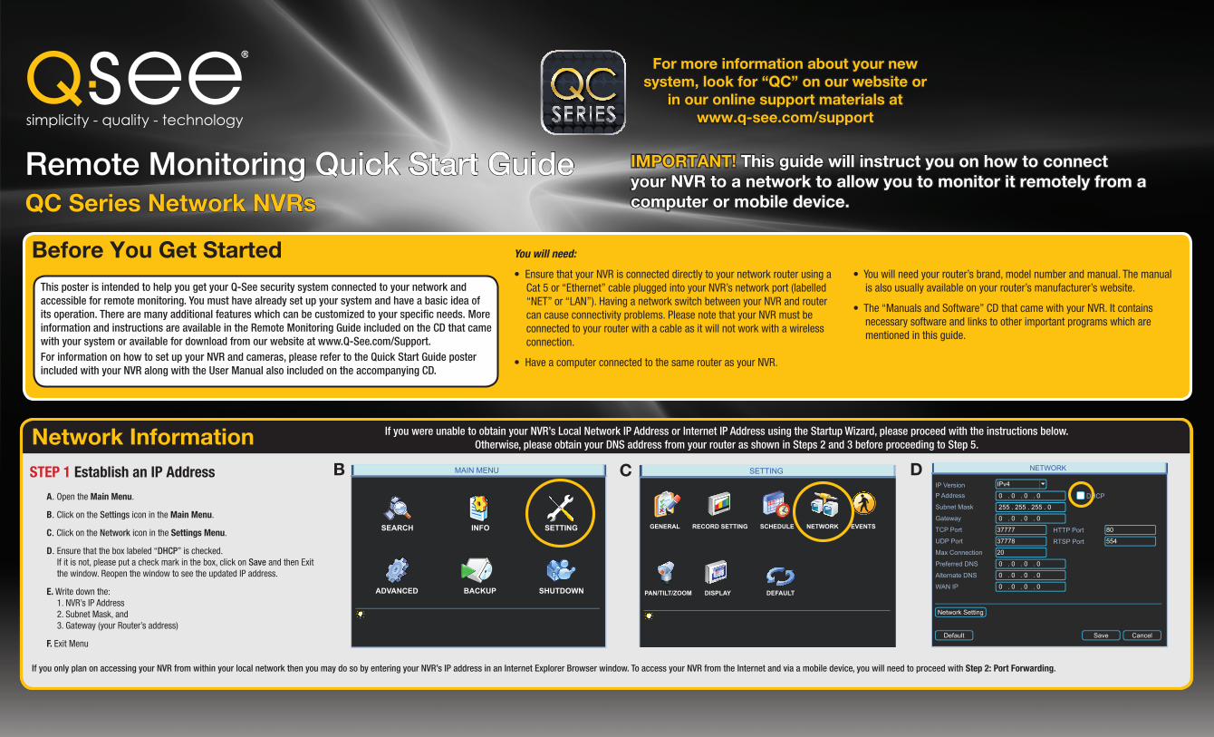
Network InformationSTEP 1 Establish an IP Address
A. Open the Main Menu.
B. Click on the Settings icon in the Main Menu.
C. Click on the Network icon in the Settings Menu.
D. Ensure that the box labeled “DHCP” is checked. If it is not, please put a check mark in the box, click on Save and then Exit
the window. Reopen the window to see the updated IP address.
E. Write down the: 1. NVR’s IP Address 2. Subnet Mask, and 3. Gateway (your Router’s address)
F. Exit Menu
B DCMAIN MENU
SEARCH INFO SETTING
ADVANCED BACKUP SHUTDOWN
SETTING
RECORD SETTINGGENERAL SCHEDULE NETWORK EVENTS
PAN/TILT/ZOOM DISPLAY DEFAULT
NETWORK
IP VersionP Address
Subnet Mask
Gateway
TCP Port
UDP Port
Max Connection
Preferred DNS
Alternate DNS
WAN IP
HTTP Port
RTSP Port
DHCP 0 . 0 . 0 . 0
0 . 0 . 0 . 0
0 . 0 . 0 . 0
0 . 0 . 0 . 0
255 . 255 . 255 . 0
0 . 0 . 0 . 0
37777
37778
80
554
20
IPv4
Default
Network Setting
Save Cancel
If you only plan on accessing your NVR from within your local network then you may do so by entering your NVR’s IP address in an Internet Explorer Browser window. To access your NVR from the Internet and via a mobile device, you will need to proceed with Step 2: Port Forwarding.
If you were unable to obtain your NVR’s Local Network IP Address or Internet IP Address using the Startup Wizard, please proceed with the instructions below. Otherwise, please obtain your DNS address from your router as shown in Steps 2 and 3 before proceeding to Step 5.
For more information about your new system, look for “QC” on our website or
in our online support materials atwww.q-see.com/support

Port ForwardingSTEP 2 Opening Ports
To confirm that your ports have been forwarded successfully, go to www.canyouseeme.org using a computer connected to the same router as the NVR.
A. Enter “85” into the box labeled “What Port?”
B. Click on the Check button
C. You should see a green “Success” message. If not, return to the NVR’s Network window and, in the Network tab, change port 85 to 81 or 83 and click Apply to save your changes before checking using that new number on CanYouSeeMe.
D. Repeat for port 37777. If there is an issue with this port, try 37000 in the same manner as above.
This website will also display your Public IP address near the top of the page above the box where you entered your port number.
OPTION B: AT&T U-verse® 2Wire® Routers OPTION A: Opening Ports Using DMZ A. On a computer connected to the same router
as the NVR, open a web browser and enter the Gateway (Router’s IP address) you obtained in Part 1 into the browser window’s address bar to open your router’s Admin Screen.
A. On a computer connected to the same router as the NVR, open a web browser and enter the Gateway (Router’s IP address) you obtained in Part 1 into the browser window’s address bar to access your router.
Browser - Windows Internet Explorer
Fine 100%
Open Port Check Tool Page Safety Tools
http://canyouseeme.org/
Protected Mode: On
Your IP: 81.919.622.24What Port?
CanYouSeeMe.org - Open Port Check Tool
Check
This page will serve as a free utility for remotely verifying a port is open or closed. It will be useful for users who wish to check to see if a server or ISP is blocking certain ports.
Success: I can see your service on 81.919.622.24 on port (85)
Your ISP is not blocking port 85
To make your NVR accessible from outside of your local network, you have to “forward” ports 85 and 37777 through your router to your NVR’s IP address. The Startup Wizard will attempt to connect you using UPnP. If you received an error message during that process, use one of the two methods below.
OR
Browser - Windows Internet Explorer
Fine 100%
Web Client Page Safety Tools
http://10.6.196.6
Protected Mode: On
LIVE SEARCH BACKUP TOOLS INFOCONFIG
2011-10-06 18:16:49
Status
P.T.Z
Color
Master StreamSub-Stream
Local Recording Status
1 2 3 4 5 6 7 8
9 10 11 12 13 14 15 16
1 2 3 4 5 6 7 8
9 10 11 12 13 14 15 16
We describe other methods, including Macintosh-specific steps in the Remote Monitoring Guide which can be found on the CD that came with your system.Please note that if you are able to use UPnP, you should NOT forward your ports as this will cause connection issues.
B. Click on the Settings tab and then Firewall. Once in Firewall, click on Applications, Pinholes and DMZ.
C. In the Select Your Computer area locate your NVR’s IP address and click on it.
D. Scroll down to select User Defined.
E. Click on Add a new user-defined application.
F. In the box labeled Application Profile Name, enter NVR.
B. Locate the DMZ settings in your router. Each manufacturer is different so please consult your router’s manual for the location of this setting. Two examples are shown at right.
G. Ensure that TCP is selected.
H. Enter 85 in the From and To boxes for Port (or Range).
I. Leave the next two boxes blank to use the default settings.
J. Click on Add to List. Your router will require you to log in to accept the settings. If you have not created your own password for your router, it is the 10-digit System Key printed on the label on your router between the square brackets “[ ]”.
K. Once your settings have been confirmed, repeat Steps H-J, this time entering 37777 for the From and To ports.
L. Click on Back and then select NVR from the list of Applications. Clicking on Add and then Save.
C. Enable DMZ.
D. Enter the NVR’s IP address (Obtained in Step 1 Obtain an IP Address, above).
E. Click on Apply or Save to preserve your settings.
This is the number which you will use to access the NVR using a web browser or your mobile device from outside of your local network (away from the building in which your NVR is located). Please note that if you had to use a different port number than 80, you will have to add a colon (:) and that port number to the end of the address shown. Example 81.919.622.24:81.
B
D
C
E
F
J
G-H
IMPORTANT! If you were able to successfully connect to your network using the Startup Wizard, you should skip to the CanYouSeeMe.org step at the bottom of this section to obtain your Public IP address.
STEP 3 Obtain DNS Before closing your router’s control window, check your router’s Status window to obtain the DNS address - you will only need to use one.
STEP 4 Confirm that Ports are Opened and Obtain Internet IP Address
Write down your network addresses:
Local Address:___________________________________
Public (Internet) IP Address: ________________________
DNS Number: ____________________________________
Browser - Windows Internet Explorer
Fine 100%
Router Page Safety Tools
http://81.919.622.24
Protected Mode: On
SETTINGS ADVANCEDSTATUS
DEVICE INFORMATION
All of your Internet and network connection details are displayed on this page.
WAN
MAC Address :IP Address :
Subnet Mask :Default Gateway :
Primary DNS Server :Secondary DNS Server :
Advanced DNS :
00:24:01:77:f9:0081.919.622.249255.255.255.081.919.622.2410.6.196.6(null)Disabled
DEVICE INFO
LOGS
STATISTICS
INTERNET SESSIONS
ROUTING
WIRELESS

Fixed Local Network Address and Domain Name System (DNS)
Most routers assign connected devices a random IP address that is not currently in use by another device on your internal network. With the exception of 2Wire brand routers, when a router or networked device reboots due to a power loss or other issue, the addresses will change and the port forwarding configuration will no longer work. For that reason, we recommend changing your NVR’s network setting to a fixed, or “static” IP address which will not change.
STEP 6 Domain Name System (DNS)
DNS enables you to take advantage of additional features including the ability to access your NVR using a conventional domain name and having your system send out e-mail alerts. To access these functions, you will need to enter the DNS number that you obtained from your router in Step 4 into the Preferred DNS box (B) into the Network Menu. Each block of numbers (between the periods) must be entered individually using the Virtual Keyboard (right) as described on the Quick Start Poster that also came with your NVR.Once you have entered the DNS number, click Save.Close the window.
STEP 5 Static Internal IP (Network) Address
Return to the Network Menu.Uncheck the box marked DHCP (A).Click Save.Proceed to Step 6 without closing the window.
NETWORK
IP VersionP Address
Subnet Mask
Gateway
TCP Port
UDP Port
Max Connection
Preferred DNS
Alternate DNS
WAN IP
HTTP Port
RTSP Port
DHCP 0 . 0 . 0 . 0
0 . 0 . 0 . 0
0 . 0 . 0 . 0
0 . 0 . 0 . 0
255 . 255 . 255 . 0
0 . 0 . 0 . 0
37777
37778
80
554
20
IPv4
Default
Network Setting
Save Cancel
B
A
SYSTEM LOGIN
User NamePassword
admin
1 2 3
54 6
87 9
0
! ? @ # $ % ^ + * - _q w e r t y u i o p |a s d f g h j k l ; Enterz x c v b n m , . Shift
Dynamic Domain Name Service (DDNS)This is an optional step which allows you to take advantage of Dynamic Domain Name Service, or DDNS. Not to be confused with DNS from Step 6, DDNS allows you to enter a conventional web address when remotely logging into your NVR from outside of your network. It also allows you to avoid having to repeat Steps 4 and 5 when/if your ISP reassigns IP addresses. Q-See offers DDNS service for free at www.MyQ-See.com and your NVR is configured accept account information from that site.
A. Open a browser window and go to www.MyQ-See.com
B. Register with the website and follow the instructions for creating a domain name. The website will display your pubic IP address and your domain name which will look like this: http://example.myq-see.com
C. In your NVR, open the Network window.
D. Click on the Network Setting button at the bottom to open the Network Setting window.
E. Check the box to the left of DDNS and double-click on DDNS itself to open the DDNS window.
F. Select MyQ-See.com in the DDNS server pull-down menu.
G. Enter your account information – including the user name and password that you used when creating your domain name .
H. Click the Save button to preserve your settings.
I. When you return to the Network window, ensure that the DDNS box is checkmarked before clicking on Save as well before closing.
NEW USER REGISTRATION
EMAIL ADDRESS
PASSWORD
FIRST NAME
LAST NAME
ANSWER
SECURITYQUESTION..
CONFRIMYOU’RE HUMAN
PASSWORDCONFIRM
SubmitSubmit ResetReset
My first phone number
New Captcha
Enter the text you see above
A-BNETWORK
IP VersionP Address
Subnet Mask
Gateway
TCP Port
UDP Port
Max Connection
Preferred DNS
Alternate DNS
WAN IP
HTTP Port
RTSP Port
DHCP 0 . 0 . 0 . 0
0 . 0 . 0 . 0
0 . 0 . 0 . 0
0 . 0 . 0 . 0
255 . 255 . 255 . 0
0 . 0 . 0 . 0
37777
37778
80
554
20
IPv4
Default
Network Setting
Save Cancel
NETWORK SETTING
IP FILTER
PPPOE
DDNS
UPNP
FTP
Register
Switch Settings
Trusted Sites : 0
No Available DDNS Setup
Port Forwarding
Mail Sever : 25
Record FTP : 461.966.106.12
0.0.0.0 : 8000
10.1.1.1
Default Save Cancel
DDNS
DDNS Type
Server IP
Port
Domain Name
User Name
Password
Update Period sec.
Enable
300
myq-see.com
85
Q-SEE DDNS
Default Save Cancel
D F
E
G
H
I

Accessing Your NVR RemotelySTEP 6 Using the Pro Surveillance Software (PSS)Now that your ports have been successfully forwarded, you are now able to access your NVR from a computer using Internet Explorer or the Pro Surveillance Software included on the CD that came with your system. PSS allows Mac and PC users a method to remotely monitor their NVR in a way that is not browser-dependent. PSS is compatible with Windows Vista and 7 as well as Mac OSX 10.6 and 10.7. The software interface is identical across computing platforms so both PC and Mac use is described below. Mac users may have to first install a helper program called XQuartz. Instructions for that additional step along with an expanded manual for the software is included on the disk.Whether you are monitoring your NVR from a computer on the same local network (LAN), or on one at a remote location (WAN/Internet), the procedure is the same. The only difference is that for LAN access you will be entering your NVR’s IP address, which you obtained in Part 1 Obtain an IP Address, while for Internet access you will use the Public IP Address which was shown at the end of Part 2 when you visited www.canyouseeme.org
A. Once you have installed PSS, click on the icon to launch it.
B. Enter the User Name and Password in the appropriate fields. The default user name and password are admin and admin. It is strongly recommended that you modify your password for improved security.
C. Before you can monitor your NVR, you must first connect to it with PSS.
1. Click on the blue Full Menu icon to the right of the Setting Manage button in the Tool Bar on the right side of the display.
2. Select Device Manage to open the Device Manage window.
PC users need only click on the Install PSS Software for Windows button, located in the Manuals and Software CD’s Remote Monitoring on-screen menu ( below, left) to begin the installation. Mac owners will need to open the CD conventionally, and navigate to the folder containing PSS (below, right) and click on the file named PSSSetup.pkg to install.
PSSPSS
3. Click the Add button and enter the NVR’s IP address (Section 1.1) or DDNS address (obtained in Section 8.5), port number, your user name and password (which are the same that you use to log into the NVR directly). You can also give the NVR an identifying name and you can add a note in the Description field.
You can also add other types of devices such as a network backup storage drive using this window. Leave Login Type at its default Network Type TCP setting.
You can return to this window to update your passwords, add or remove other devices and make network access changes if need be.
4. A prompt will pop up at the bottom right of the screen to indicate that the NVR has been added to the program.
D. The NVR will now appear in the Device List at the top of the Tool Bar. Click on the device name to expand the listing and you can add cameras.
E. Choose the screen view format you wish to use and then click on the segment of the screen where you want to place the first camera. Then, click on the camera number in the Device List to add that camera. Repeat by selecting a new area. The area highlighted in green is the current camera view. Clicking on a camera icon while a camera view is highlighted will replace that view with the channel you just selected.
Live monitoring and recorded video playback takes place in the Real-Time Monitor section of the window. The number of screens being viewed at once is set with the Image View Options at the bottom of the screen, but at any time, you can double-click on a channel in multi-view mode to make it a single-screen view. Double-clicking on the screen will return it to its place in the multi-view display.

Questions? 24/7 Technical Resources at www.Q-See.com/support
www.Q-See.com
Email AlertsSTEP 8 Sending EmailYour NVR can send e-mail notifications to up to three email addresses. While only one recipient can be set up within the NVR itself, additional recipients can be specified using PSS. Please see the Remote Monitoring Guide or the PSS manual for specific instructions if you need to add more than one receiving email address. Depending on your NVR’s settings, the system can generate heavy email traffic. For that reason, we recommend creating a dedicated email address specifically for the system to send alert notices. If you do not have your own email system
STEP 9 Setting E-mail TriggersThere are several types of events that you can set to trigger an e-mail alert. Alerts can be triggered when motion is detected, if the hard drive fails, or video is lost.Full explanations for setting these triggers are available in your manual be we present some highlights here:
A. Click on the Network Settings button at the bottom of the window. Ensure that the box to the left is checked before clicking on Email in the Network Settings window.
B. Fill out the required information. Gmail settings are shown:
SMTP Server – smtp.gmail.com Port – 465 Anonymous – Leave this unchecked for Gmail. Private mail
servers may allow you to send e-mail without a user name or password.
User Name and Password – Enter the email address along with the password you used to create the account.
Receiver– This is the email address that will receive the alerts.
Sender – This is the ID that will show up in the “from” field on the e-mail. It can be the sending email address, or it can be a nickname, such as the model or location of the NVR.
Title – Putting in a distinct subject line for your email alerts will help you organize and keep track of the email traffic generated by your system.
Attachments – Enabling this allows your NVR to send emails with snapshots attached.
Encrypt Type – Select SSL for Gmail. Other services may vary.
Event Interval – This will limit the number of emails sent within a specified time period. The minimum delay is 3
NETWORK
IP VersionP Address
Subnet Mask
Gateway
TCP Port
UDP Port
Max Connection
Preferred DNS
Alternate DNS
WAN IP
HTTP Port
RTSP Port
DHCP 0 . 0 . 0 . 0
0 . 0 . 0 . 0
0 . 0 . 0 . 0
0 . 0 . 0 . 0
255 . 255 . 255 . 0
0 . 0 . 0 . 0
37777
37778
80
554
20
IPv4
Default
Network Setting
Save Cancel
SMTP Server
Anonymous
User Name
Receiver
Sender
Title
Attachment
Encrypt Type
Event Interval
Health Enable
Interval
Min.
Min.
Port
Password
DVR ALERT
smtp.gmail.com 465
3
60
NONE
TestOKDefault Cancel
(such as corporate mail server) you should consider using a free e-mail provider. However, because many free email services allow only a limited amount of email traffic we specifically recommend using Google’s Gmail service with its higher limit. Similarly, you will want the alert emails to go to a different account than the one sending them. This will ease your management of these alerts. Other services will have different values and these can be found in that provider’s Options settings.
minutes. Health Enable – Checking this box will allow the NVR to regularly check
that the email account can be reached. You can adjust the frequency of this check using the Interval setting.
C. Press the Test button. The NVR will check to see if it can connect to the mail
server. A message will pop up indicating success or error.
D. Click OK to save your settings before closing the window.
E. Make sure that the check box next to Email is selected in the menu before
clicking on Save at the bottom of the window to save your settings.
EVENTS
Event Type
Enable
Region
Trigger Period
Alarm OutShow Message Alarm upload Send EmailRecord ChannelPTZ ActivationTourSnapshot
Hold Time
Record Continue
sec.
Channel
Sensitivity
Motion Detect 1
3
0
sec.0
Alarm Continue sec.10
Select
Select
Set
Copy Paste Default Save Cancel
1 2 3 4
1 2 3 41 2 3
1 2 3
4
5
55
6
66
7
77
8
88
RECORD SETTING
Main Stream
H.264
Extra Stream
Channel
Compression
Resolution
Frame Rate (FPS)
Bit Rate Type
Bit Rate (Kb/S)
Reference Bit Rate 384-2048Kb/S
Audio/Video
1
D1
25
Constant
2049
H.264
CIF
7
Constant
160
OVERLAY
SNAPSHOT
Copy Paste Default Save Cancel
SNAPSHOT
Save Cancel
Mode
Image Size
Image Quality
Snapshot Frequency
Trigger
D1
4
1 SPL
Your NVR can send e-mails with still image snapshots attached when an event occurs. Set the number of snapshots, the time between them and their quality through the Record Setting menu. See Section 4.3 in the User Manual.
Set which type of event triggers an email plus which cameras will take snapshots in the Events menu. See Section 3.7 in the User Manual.
Customize alarm responses to motion detection and video loss in the Alarms menu.See Chapter 6 in the User Manual.
ALARM
Trigger Period
Alarm Out
Show Message
Record Channel
PTZ Activation
Tour
Snapshot
Buzzer
Alarm Upload
Event Type
Enable
Hold Time
Alarm Continue
Rec. Continue
sec.
sec.
Alarm In
Type
Local Alarm 1
Normal Open
Send Email
Set
Set
10
sec.10
5
Default Copy Save Cancel
1 2 3 4
1 2 3 4
1 2 3 4
1 2 3