Embed Size (px)
Citation preview

This manual contains important safety information and must be carefully read in its entirety and understood prior to installation by all personnel who install, operate and/or maintain this product.
Product warranty information is available at www.quincycompressor.com/about/warranties
Manual No. 50118-106
January 2013 Edition
Instruction Manual
QRD®
Series


QRD Series Quincy Compressor
50118-106, January 2013 1 3501 Wismann Lane, Quincy IL - 62305-3116
ContentsSECTION 1 SAFETY Safety First ............................................................................................................................................................2Summary of Changes ............................................................................................................................................4
SECTION 2 SYSTEM DYNAMICSDescription & Application ....................................................................................................................................5Principles of Compression Cycles .........................................................................................................................5Principles of Lubrication Systems .......................................................................................................................5Principles of Cooling Systems ..............................................................................................................................5Principles of Dryers & Filters ..............................................................................................................................6Control Components .............................................................................................................................................6Control Versions ....................................................................................................................................................6Specifications .......................................................................................................................................................11
SECTION 3 INSTALLATIONReceiving Delivery ..............................................................................................................................................14Freight Damage ..................................................................................................................................................14Location ...............................................................................................................................................................15Electrical Supply Requirements.........................................................................................................................16Mounting .............................................................................................................................................................17System Components ............................................................................................................................................17Induction System ................................................................................................................................................19Compressed Air Discharge System ....................................................................................................................19
SECTION 4 START-UP & OPERATIONPre-Starting Checklist ........................................................................................................................................24Initial Starting & Operating ..............................................................................................................................25Important Operating Instructions .....................................................................................................................25Daily Starting Checklist .....................................................................................................................................25
SECTION 5 MAINTENANCE Stopping for Maintenance ..................................................................................................................................27Maintenance Schedule ........................................................................................................................................27Pulley / Sheave Alignment & Belt Tension ........................................................................................................28Pressure Switch Adjustment ..............................................................................................................................29Torque Specifications ..........................................................................................................................................30Pilot Valve Adjustments ......................................................................................................................................31
SECTION 6 TROUBLESHOOTINGTroubleshooting ..................................................................................................................................................32
SECTION 7 REFERENCE INFORMATIONApproximate Capacity Correction for Altitude..................................................................................................35Decal Locations ...................................................................................................................................................36
QRD Series Quincy Compressor
50118-106, January 2013 2 3501 Wismann Lane, Quincy IL - 62305-3116
SECTION 1 SAFETY
Safety FirstAt Quincy Compressor safety is not only a primary concern, but a faithfully performed practice. Beginning with the design stage, safety is built into “The World’s Finest Compressor”. It is the inten tion of this manual to pass along the “safety first” concept to you by providing safety precautions throughout its pages.
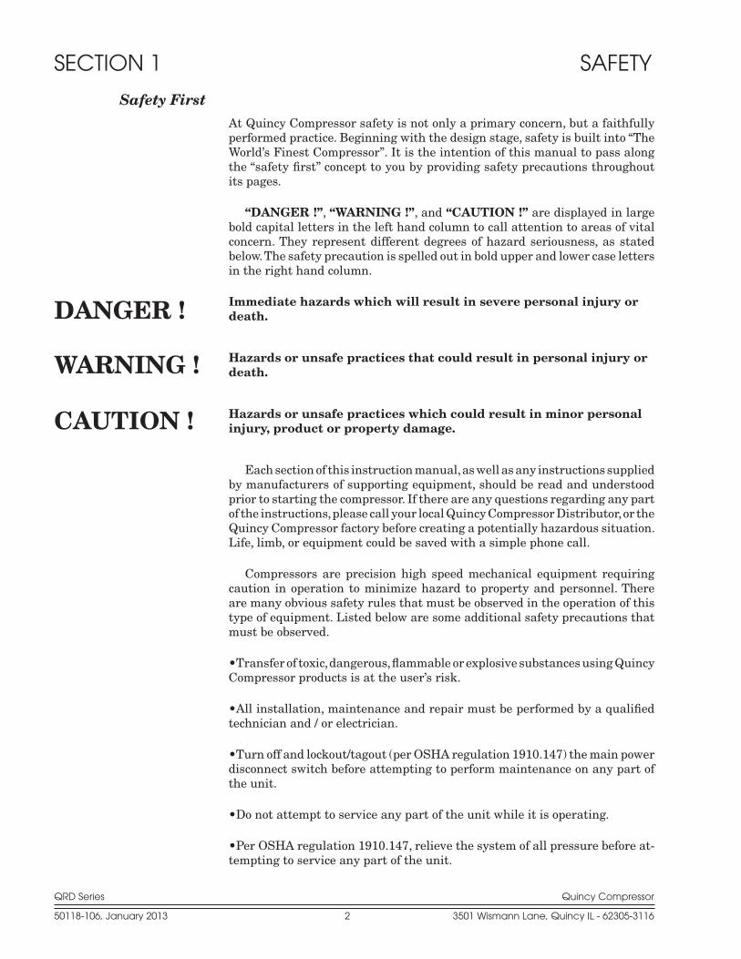
“DANGER !”, “WARNING !”, and “CAUTION !” are displayed in large bold capital letters in the left hand column to call attention to areas of vital concern. They represent different degrees of hazard seriousness, as stated below. The safety precaution is spelled out in bold upper and lower case letters in the right hand column.
Immediate hazards which will result in severe personal injury or death.
Hazards or unsafe practices that could result in personal injury or death.
Hazards or unsafe practices which could result in minor personal injury, product or property damage.
Each section of this instruction manual, as well as any instruc tions supplied by manufacturers of supporting equipment, should be read and understood prior to starting the compressor. If there are any questions regarding any part of the instructions, please call your local Quincy Compressor Distributor, or the Quincy Compressor factory before creating a potentially hazardous situa tion. Life, limb, or equipment could be saved with a simple phone call.
Compressors are precision high speed mechanical equipment requiring caution in operation to minimize hazard to property and personnel. There are many obvious safety rules that must be ob served in the operation of this type of equipment. Listed below are some additional safety precautions that must be observed.
•Transfer of toxic, dangerous, flammable or explosive substances using Quincy Compressor products is at the user’s risk.
•All installation, maintenance and repair must be performed by a qualified technician and / or electrician.
•Turn off and lockout/tagout (per OSHA regulation 1910.147) the main power disconnect switch before attempting to perform maintenance on any part of the unit.
•Do not attempt to service any part of the unit while it is operating.
•Per OSHA regulation 1910.147, relieve the system of all pressure before at-tempting to service any part of the unit.
WARNING !
CAUTION !
DANGER !

QRD Series Quincy Compressor
50118-106, January 2013 3 3501 Wismann Lane, Quincy IL - 62305-3116
•Do not operate the unit with any of its safety guards, shields, or screens removed.
•Do not remove or paint over any DANGER!, WARNING!, CAUTION!, or instructional materials attached to the compressor. Lack of information re-garding hazardous conditions can cause property damage or personal injury.
•Periodically check all pressure relief valves for proper operation.
•Do not change the pressure setting of the pressure relief valve, re strict the function of the pressure relief valve, or replace the pressure relief valve with a plug.
•Do not install a shutoff valve in the compressor discharge line with out first installing a pressure relief valve of proper size and design between the shutoff valve and the compressor.
•Do not use plastic pipe, rubber hose, or lead-tin soldered joints in any part of the compressed air system.
•Alterations must not be made to this compressor without Quincy Compres-sor’s approval.
•Be sure that all tools, shipping and installation debris have been re moved from the compressor and installation site prior to starting the compressor.
•Do not operate the compressor in excess of the ASME pressure vessel rating for the receiver or the service rating of the compressor, whichever is lower.
•Make a general overall inspection of the unit daily and correct any unsafe situations. All fasteners must be kept tight.
•Reckless behaviour of any kind involving compressed air is dangerous and can cause very serious injury to the participants.
•Provisions should be made to have the instruction manual readily available to the operator and maintenance personnel. If for any reason any part of the manual becomes illegible or the manual is lost, have it replaced immediately. The instruction manual should be read periodically to refresh one’s memory. It may prevent a seri ous or fatal accident.
•Never use a flammable or toxic solvent for cleaning the air filter or any parts.
•Wear safety glasses and hearing protection during operation, service and maintenance procedures.
Air used for breathing or food processing must meet OSHA 29 CFR 1910.134 or FDA 21 CFR 178.3570 or NFPA 99 regulations. Failure to do so may cause severe injury or death.
The owner, lessor or operator of any compressor unit manu factured by Quincy Compressor is hereby warned that failure to ob serve the above safety precautions may result in serious injury to personnel and/or damage to property.
DANGER !
QRD Series Quincy Compressor
50118-106, January 2013 4 3501 Wismann Lane, Quincy IL - 62305-3116
Quincy Compressor neither states as fact, nor in any way implies that the above list of safety precautions is an all inclusive list, the observance of which will prevent all damage to property or injury to personnel.
Every effort has been taken to ensure that complete and correct instructions have been included in this manual. However, possible product updates and changes may have occurred since this printing. Quincy Compressor reserves the right to change specifications with out incurring any obligation for equip-ment previously or subse quently sold.
Summary of Changes to This Manual(since previous printing dated September 2009):
· Removed warranty statement and added URL address on front cover for warranty information available on the Quincy Compressor website.
· Edited Electrical Supply Requirements to include Canadian Standards Association (CSA) requirements.
· Added Air Tank Inspection information and a graphic explanation of the tank drain decal.
QRD Series Quincy Compressor
50118-106, January 2013 5 3501 Wismann Lane, Quincy IL - 62305-3116
SECTION 2 SYSTEM DYNAMICS
Description & ApplicationThe Quincy Compressor QRD Series consists of heavy duty indus trial, belt driven, single or two stage air cooled compressors. Single stage compressors are capable of delivering up to 100 PSIG continuously. Two stage compres-sors can deliver up to 150 PSIG contin uously, depending upon operating and maintenance parameters (consult factory).
Principles of Compression Cycles Single Stage Compressors
During the downstroke of a single stage compressor, air is drawn through an intake valve in the head of the compressor and into the cylinder. At the bot-tom of the stroke, the intake valve closes and air is trapped in the cylinder. The air is then compressed in the cylinder during the upstroke of the piston. Total compression, from atmo spheric pressure to the final discharge pressure, is accomplished in one stroke of the piston.
Two Stage Compressors
During the downstroke of the piston of a two stage compressor, air is drawn through an intake valve in the head of the compressor into the low pressure cylinder and compressed during the upstroke of the piston.
The compressed air is then released through a discharge valve in the head of the compressor to an intercooler (usually finned tub ing) where the heat resulting from compression is allowed to dissipate. The cooler compressed air is then drawn into a second compression cylinder, the high pressure cylinder, for compression to final pressure.
From there the compressed air is released through a discharge valve to an air receiver tank or directly to a network of compressed air supply lines. In one revolution of the crankshaft a compression cycle is completed.
Principles of Lubrication SystemsNo lubrication is required for the pistons and cylinders. PTFE® composite compression rings provide sealing and PTFE® composite rider rings carry the thrust loads. The wrist pin needle bearings are grease lubricated and require maintenance (Refer to SECTION 5, Maintenance Schedule). All bearings on the crankshaft are sealed and lubricated for the life of the bearing.
Principles of Cooling SystemsFan blades of the compressor sheave force ambient air across fins of a discharge manifold and the cylinder heads, and intercooler fins of two stage compres-sors, to cool the compressor. QRD series compressors are normally set up at the factory with a sheave that turns in a counterclockwise rotation (refer to directional arrow on sheave). Due to standard drive motor limitations, it is recommended that the compressor be operated in temperatures under 104°F.
QRD Series Quincy Compressor
50118-106, January 2013 6 3501 Wismann Lane, Quincy IL - 62305-3116
Principles of Dryers & FiltersMoisture occurs naturally in air lines as a result of compression. Moisture vapor in ambient air is concentrated when pressurized and condenses when cooled in downstream air piping. Compressed air dryers reduce the moisture vapor concentration and prevent water formation in compressed air lines. Dryers are a recommended companion to filters, aftercoolers, and automatic drains for improving the productivity of compressed air systems.
Water and moisture vapor removal increases the efficiency of air operated equipment, reduces contamination and rusting, increases the service life of pneumatic equipment and tools, prevents air line freeze-ups, and reduces product rejects.
Control ComponentsHead Unloader: Pneumatic control device designed to allow the compressor to run continuously without compressing air until there is a demand for more compressed air.
Pilot Valve: Used in conjunction with head unloaders when the compressor is to run continuously and an operating pressure range is to be maintained. Refer to your parts manual for correct pilot valve, ranges and settings.
Pressure Switch: Used for start/stop appli cations. The pressure switch de-tects the demand for compressed air and allows the unit to start. When the de mand is satisfied, the unit stops.
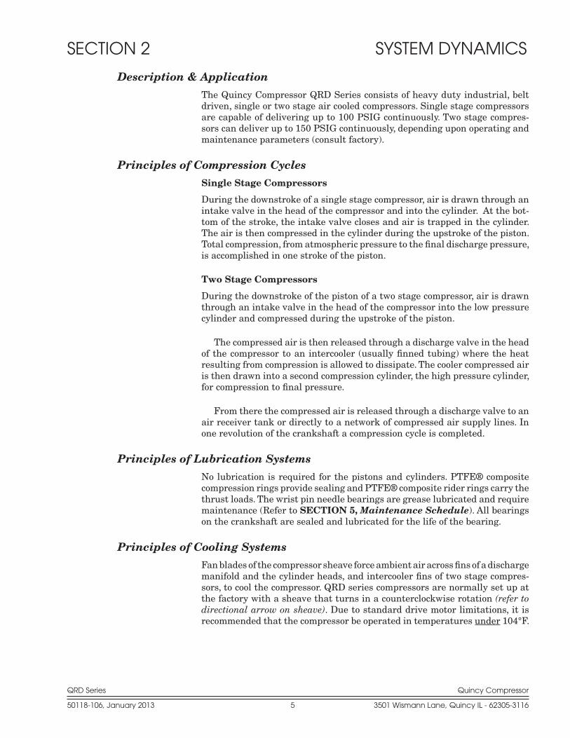
Control VersionsQRDS single stage compressors can be operated with one of three control con-figurations: Control Version L, S or LVD.
Control Version L (for start/stop opera-tion, see Fig. 2-1, Control Version L Schematic) automatically starts and stops the compressor in response to a pressure switch. The pressure switch detects the demand for compressed air and allows the unit to start. When the demand is satisfied, the pressure switch stops the unit.
Fig. 2-1 Control Version L Schematic(start/stop operation)
SINGLE STAGE QRDS
QRD Series Quincy Compressor
50118-106, January 2013 7 3501 Wismann Lane, Quincy IL - 62305-3116
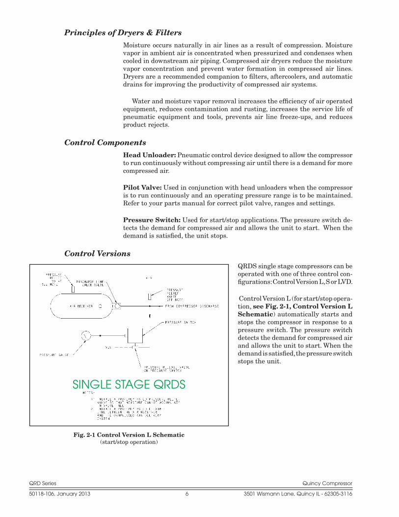
Control Version S (for continuous run or load/unload operation, see Fig. 2-2, Control Version S Schematic) allows the compressor to run continuously, with the unit loading and unloading in response to a pilot valve. This control version should be used whenever the compressor must start more than 6 times per hour. If the demand for com-pressed air is continuous and exceeds one-half or more of the compressor’s capacity, Control Version S or LVD should be used.
Control Version LVD (see Fig. 2-3, Control Version LVD Schemat-ic) provides for the selec-tion of either start/stop or continuous run operation. To operate the compressor in the start/stop mode, screw the knurled knob on the pilot valve all the way in. (Note : The pilot valve cut-out setting must be set lower than the pressure switch cut-out setting. This will ensure that the compressor will not op-erate in the continuous run mode.)
To operate the compres-sor in the continuous run mode, turn the knurled knob on the pilot valve out.
Fig. 2-2 Control Version S Schematic(continuous run operation)
Fig. 2-3 Control Version LVD Schematic(dual control operation)
SINGLE STAGE QRDS
SINGLE STAGE QRDS

QRD Series Quincy Compressor
50118-106, January 2013 8 3501 Wismann Lane, Quincy IL - 62305-3116
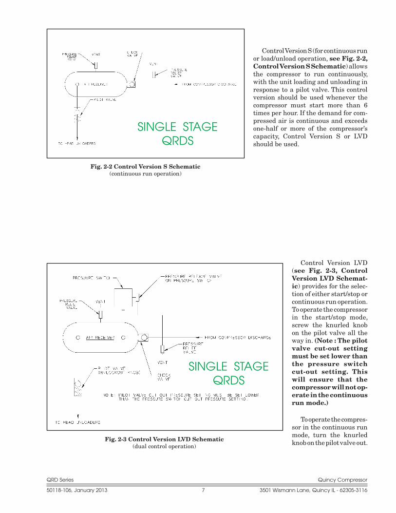
QRDT two stage compressors can be operated with either control version SV or SVD.
Control Version SV (see Fig.s 2-4, 2-5 & 2-6 Control Version SV Schematic) provides for the selection of start/stop or continuous run operation via a selector switch located on the electrical control panel.
Fig. 2-4 Control Version SV Schematic(solenoid valve dual control operation)
Fig. 2-5 Control Version SV Schematic(solenoid valve dual control operation; base mount unit)
TWO STAGE QRDT
TWO STAGE QRDT
QRD Series Quincy Compressor
50118-106, January 2013 9 3501 Wismann Lane, Quincy IL - 62305-3116
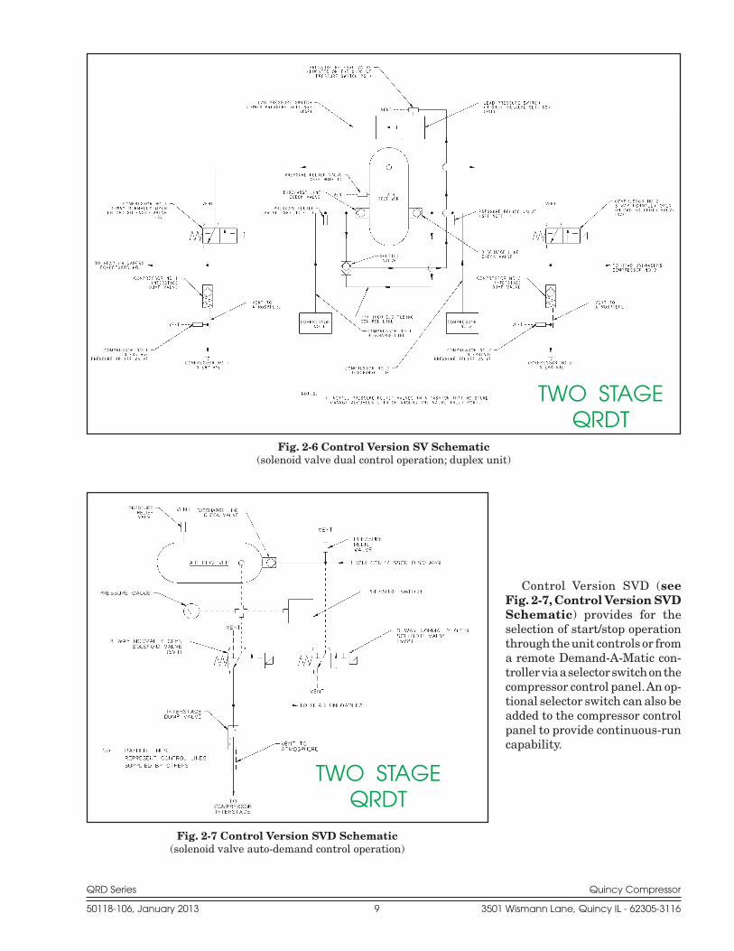
Control Version SVD (see Fig. 2-7, Control Version SVD Schematic) provides for the selection of start/stop operation through the unit controls or from a remote Demand-A-Matic con-troller via a selector switch on the compressor control panel. An op-tional selector switch can also be added to the compressor control panel to provide continuous-run capability.
Fig. 2-6 Control Version SV Schematic(solenoid valve dual control operation; duplex unit)
TWO STAGE QRDT
Fig. 2-7 Control Version SVD Schematic(solenoid valve auto-demand control operation)
TWO STAGE QRDT
QRD Series Quincy Compressor
50118-106, January 2013 10 3501 Wismann Lane, Quincy IL - 62305-3116
Electrical Control Operation
A wiring diagram is provided with all QRD units and can be found inside the control panel.
Switches
“START” : This push button starts the compressor. It must be depressed after power interruption or other unit shutdown.
“STOP” : Stops the motor but does not unload the receiver. Do not service the unit unless the control is off and the power is disconnected and locked out!
“HAND” : Will operate the motor continuously. The unit will load and unload in response to the pilot valve.
“AUTO” : Provides unattended start/stop operation. The unit will start auto-matically, load, and stop in response to the automatic controls.
Indicators
“POWER” : Indicates AC power is present inside the con-trol panel. Do not open the panel door or service the unit until power is disconnected and locked out!
“HIGH AIR TEMPERATURE” : Indicates high air tem-perature, power outage, or other shutdown has occured. Allow the unit to cool and correct the problem before restarting the unit.
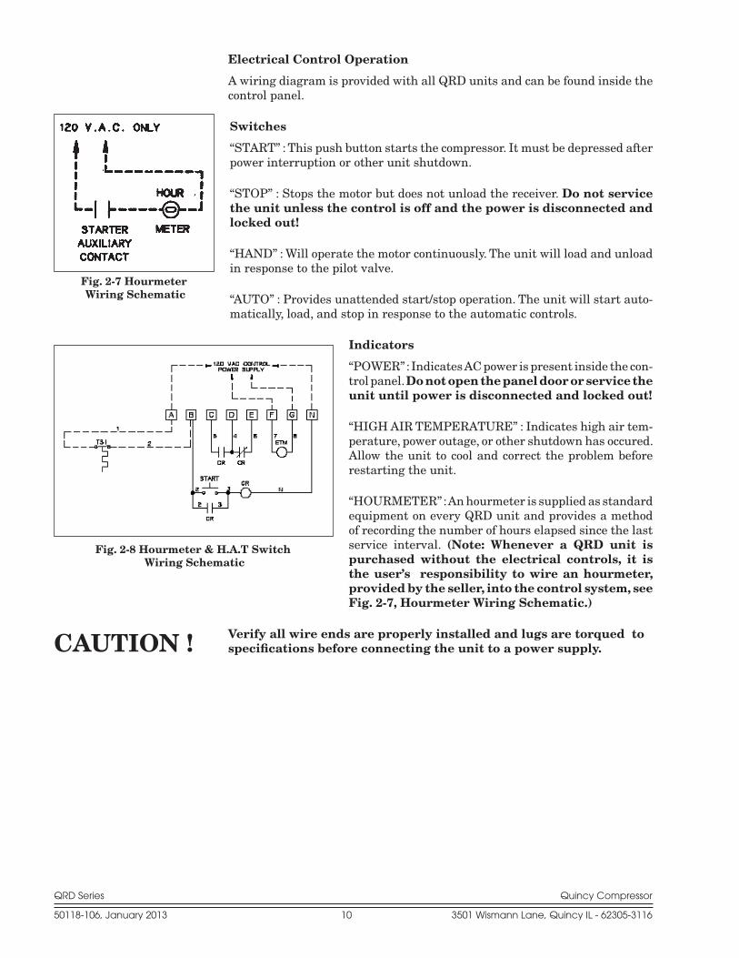
“HOURMETER” : An hourmeter is supplied as standard equipment on every QRD unit and provides a method of recording the number of hours elapsed since the last service interval. (Note: Whenever a QRD unit is purchased without the electrical controls, it is the user’s responsibility to wire an hourmeter, provided by the seller, into the control system, see Fig. 2-7, Hourmeter Wiring Schematic.)
Verify all wire ends are properly installed and lugs are torqued to specifications before connecting the unit to a power supply.
Fig. 2-7 Hourmeter Wiring Schematic
Fig. 2-8 Hourmeter & H.A.T Switch Wiring Schematic
CAUTION !

QRD Series Quincy Compressor
50118-106, January 2013 11 3501 Wismann Lane, Quincy IL - 62305-3116
SpecificationsQRDS Single Stage Single Cylinder Compressors
Compressor Motor No. of Bore & Stroke RPM *Piston Displacement Model h.p. Cylinders (inches) Range Cubic Ft. per Rev.
QRDS-2 2 1 4.000 x 2.000 400-1060 .01454 QRDS-3 3 1 4.750 x 2.000 400-1060 .02051 QRDS-5 5 1 5.250 x 2.000 400-1060 .02506
·Allowable Ambient Temperature Range +32° F to 104° F·Inlet Connections 1 npt (female)·Discharge Manifold Connections 1 npt (female)·Bare Compressor Weight 120 lbs.·Compressor with Flywheel 155 lbs.
QRDS Single Stage Two Cylinder Compressors
Compressor Motor No. of Bore & Stroke RPM *Piston Displacement Model h.p. Cylinders (inches) Range Cubic Ft. per Rev.
QRDS-7.5 7.5 2 4.750 x 2.375 500-1000 .04871 QRDS-10 10 2 5.250 x 2.375 400-1011 .05951
·Allowable Ambient Temperature Range +32° F to 104° F·Inlet Connections 1 npt (female)·Discharge Manifold Connections 1 1/4 npt (female)·Bare Compressor Weight 201 lbs.·Compressor with Flywheel 270 lbs.
QRDS Single Stage Three Cylinder Compressors
Compressor Motor No. of Bore & Stroke RPM *Piston Displacement Model h.p. Cylinders (inches) Range Cubic Ft. per Rev.
QRDS-15 15 3 4.750 x 2.375 500-1040 .07307 QRDS-20 20 3 5.250 x 2.375 500-1040 .08926
·Allowable Ambient Temperature Range +32° F to 104° F·Inlet Connections 1 npt (female)·Discharge Manifold Connections 1 1/4 npt (female)·Bare Compressor Weight 15 h.p. = 280 lbs. 20 h.p. = 315 lbs.·Compressor with Flywheel 15 h.p. = 415 lbs. 20 h.p. = 450 lbs.
* Cubic Feet per Revolution x RPM = CFM
QRD Series Quincy Compressor
50118-106, January 2013 12 3501 Wismann Lane, Quincy IL - 62305-3116
* Cubic Feet per Revolution x RPM = CFM
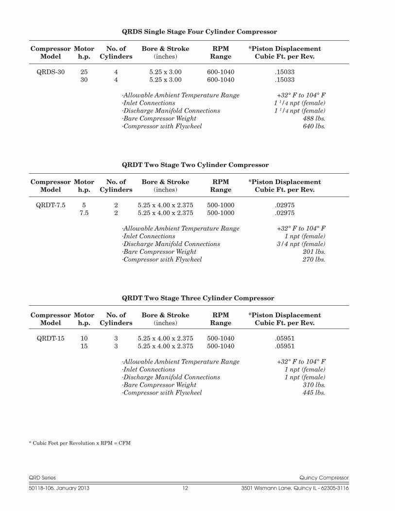
QRDS Single Stage Four Cylinder Compressor
Compressor Motor No. of Bore & Stroke RPM *Piston Displacement Model h.p. Cylinders (inches) Range Cubic Ft. per Rev.
QRDS-30 25 4 5.25 x 3.00 600-1040 .15033 30 4 5.25 x 3.00 600-1040 .15033
·Allowable Ambient Temperature Range +32° F to 104° F·Inlet Connections 1 1/4 npt (female)·Discharge Manifold Connections 1 1/4 npt (female)·Bare Compressor Weight 488 lbs.·Compressor with Flywheel 640 lbs.
QRDT Two Stage Two Cylinder Compressor
Compressor Motor No. of Bore & Stroke RPM *Piston Displacement Model h.p. Cylinders (inches) Range Cubic Ft. per Rev.
QRDT-7.5 5 2 5.25 x 4.00 x 2.375 500-1000 .02975 7.5 2 5.25 x 4.00 x 2.375 500-1000 .02975
·Allowable Ambient Temperature Range +32° F to 104° F·Inlet Connections 1 npt (female)·Discharge Manifold Connections 3/4 npt (female)·Bare Compressor Weight 201 lbs.·Compressor with Flywheel 270 lbs.
QRDT Two Stage Three Cylinder Compressor
Compressor Motor No. of Bore & Stroke RPM *Piston Displacement Model h.p. Cylinders (inches) Range Cubic Ft. per Rev.
QRDT-15 10 3 5.25 x 4.00 x 2.375 500-1040 .05951 15 3 5.25 x 4.00 x 2.375 500-1040 .05951
·Allowable Ambient Temperature Range +32° F to 104° F·Inlet Connections 1 npt (female)·Discharge Manifold Connections 1 npt (female)·Bare Compressor Weight 310 lbs.·Compressor with Flywheel 445 lbs.

QRD Series Quincy Compressor
50118-106, January 2013 13 3501 Wismann Lane, Quincy IL - 62305-3116
* Cubic Feet per Revolution x RPM = CFM
QRDT Two Stage Four Cylinder Compressors
Compressor Motor No. of Bore & Stroke RPM *Piston Displacement Model h.p. Cylinders (inches) Range Cubic Ft. per Rev.
QRDT-30 20 4 7.12 x 4 x 3.00 500-1040 .13825 25 4 7.12 x 4 x 3.00 500-1040 .13825 30 4 7.12 x 4 x 3.00 500-1040 .13825
·Allowable Ambient Temperature Range +32° F to 104° F·Inlet Connections 2 npt (female)·Discharge Manifold Connections 1 1/2 npt (female)·Bare Compressor Weight 518 lbs.·Compressor with Flywheel 680 lbs.

QRD Series Quincy Compressor
50118-106, January 2013 14 3501 Wismann Lane, Quincy IL - 62305-3116
SECTION 3 INSTALLATION
Receiving DeliveryImmediately upon receipt of compressor equipment and prior to completely uncrating, the following steps should be taken:
Step 1) Inspect compressor equipment for damage that may have occurred during shipment. If any damage is found, de mand an inspection from the carrier. Ask the carrier how to file a claim for shipping damages. (Refer to SECTION 3, Freight Damage for complete details.) Shipping damage is not covered by Quincy Com-pressor warranty.
Step 2) Insure that adequate lifting equipment is available for moving the compressor equipment.
Improper lifting can result in component or system damage, or personal injury. Follow good shop practices and safety procedures when moving the unit.
Step 3) Read the compressor nameplate to verify the model and size or-dered.
Step 4) Read the motor nameplate to verify that the volt, phase and hertz ratings are the same as the electrical power supply connecting to the motor. NOTE: Do not use a triple voltage (115/208-230) single-phase motor or (208-230/460) 3-phase motor for 208 volts or lower. Use a 200 volt or 208 volt motor only.
Step 5) Read the pressure relief valve nameplate to be sure it does not exceed the working pressure shown on the compressor or any other component in the system.
Step 6) Read and understand the safety precautions contained within this manual. The successful and efficient operation of compressor equipment depends largely upon the amount of care taken to install and maintain the equipment. Quincy Compressor strongly recommends that any or all person(s) in charge of install-ing, maintaining, or servic ing one of our compressors read and understand the entire contents of this manual in order to perform such duties safely and efficiently.
Freight DamageIt is extremely important that you examine every carton and crate as soon as you receive it. If there is any obvious damage to the shipping container, have the delivering carrier sign the freight bill, noting the apparent damage, and request a damage report.
If concealed damage is discovered at a later date, the carrier must be notified within 15 days of initial receipt of freight. Concealed shipping damage is not covered by Quincy Compressor Warranty.
CAUTION !
QRD Series Quincy Compressor
50118-106, January 2013 15 3501 Wismann Lane, Quincy IL - 62305-3116
Contact the carrier as soon as possible, giving them an opportunity to inspect the shipment at the premises where the delivery was made. Do not move the damaged freight from the premises where the original delivery was made. Retain all containers and packing for inspection by the carrier.
A claim form can be requested from the carrier: Standard Form for Pre-sentation of Loss and Damage Claims (form # 3208). Your claim will need to be substantiated with the following documents:
a.) form #3208
b.) original bill of lading
c.) original paid freight bill
d.) original invoice or certified copy
e.) other particulars obtainable in proof of loss or damage (photos, dam-age inspection, etc.)
The proper description and classification of our product in the National Motor Freight Classification 100-H, contained in item 118100, reads as fol-lows: Compressors, air, or air ends: with or without air tanks, hose or nozzles, mounted or not mounted.”
We suggest that these instructions be circulated to your shipping and receiving personnel.
LocationQuincy air compressors must be installed and operated in a secure, upright and level position in an area that is clean, dry, well lighted, and adequately ventilated not closer than 24 inches to a wall or another compressor. Ample circu la tion of air across the compressor cylinders, heads and cooler (if so equipped) must be provided. Compressors should be located in such a way that the sheave fan of one compressor does not blow hot air towards another compressor.
QRD compressors are equipped with ventilated crankcases to promote cooling of internal parts. Excessive crankcase moisture could result in undue wear, unecessary maintenance and reduced performance. Indoor installation of QRD Series compressors is recommended. If it is necessary to install the compressor outside, it must be protected from rain and other sources of moisture.
Protect compressor from rain and other water spray.
Inspection and mainte nance checks are required daily. Therefore, suffi-cient space needs to be provided around the compressor for safe and proper in spection, cleaning, and maintenance. If at all possible, the pulley drive sys-tem (i.e. motor pul ley, compressor sheave, belts and guard) should be located next to a wall to minimize any danger created by the drive system while the compressor is operating.
Due to standard drive motor limitations, it is recommended that the compressor be operated in temperatures under 104°F. In cold cli mates, the compressor should be installed in a heated building.
CAUTION !

QRD Series Quincy Compressor
50118-106, January 2013 16 3501 Wismann Lane, Quincy IL - 62305-3116
Do not operate this compressor in ambient temperatures lower than 32° F.
If the air receiver is going to be subject to temperatures of 32°F or below, provisions must be made to guard against freezing of the pressure relief valves, pressure gauge, check valve, and moisture drain.
Under no circumstances should a compressor be used in an area that may be exposed to toxic, volatile, or corrosive atmo sphere. Do not store toxic, volatile, or corrosive agents near the compressor.
Noise
Noise is a potential health hazard that must be considered. There are federal and local laws governing acceptable noise levels. Check with local officials for specifications.
Excessive noise can be effectively reduced through various meth ods. Total enclosures, intake silencers, baffle walls, relocating or iso lating the compressor can reduce noise levels. Care must be taken when constructing total enclosures or baffle walls. If not properly constructed or positioned, they could contribute to unacceptable noise levels or over heating. Consult your local Quincy Com-pressor Distributor if assis tance is required.
Unusual noise or vibration indicates a problem. Do not operate the compressor until the source has been identified and corrected.
Electrical Supply RequirementsThe electrical installation of this unit must be performed by a qualified electri-cian in accordance with the National Electrical Code (NEC) or the Canadian Electrical Code (CEC), the National Electrical Safety Code (NESC), OSHA and/or state and local codes. Failure to abide by the national, state and local codes may result in physical harm and/or property damage.
Before installation, the electrical supply must be checked for adequate wire size and transformer capacity. Verify that the electrical supply voltage matches the requirements of the motor. A suitable circuit breaker or fused disconnect switch should be provided. When a 3 phase motor is used to drive a compressor, any unreasonable voltage imbalance between the legs must be eliminated and any high or low voltage corrected to prevent excessive current draw. Note: This unit must be grounded.
High voltage may cause personal injury or death. Disconnect and lockout/tagout per OSHA regulation 1910.147 all electrical power supplies before opening the electrical enclosure or servic ing.
Never assume a compressor is safe to work on just because it is not operating. It could restart at any time. Follow all safety precau-tions outlined in SECTION 5, Stopping For Maintenance.
NEMA electrical enclosures and components must be appropriate to the area installed.
WARNING !
CAUTION !
DANGER !
CAUTION !
WARNING !
CAUTION !
QRD Series Quincy Compressor
50118-106, January 2013 17 3501 Wismann Lane, Quincy IL - 62305-3116
Overload Relay
An overload relay monitors the compressor motor electrical current and turns the compressor motor off when an overload is sensed. It is mounted on the bottom of the motor starter. The overload relay is designed for motors with a 1.15 service factor. The overload relay setting should be adjusted to the mo-tor nameplate amp rating. If the motor has a service factor rating other than 1.15, the overload relay setting must be adjusted to compensate. Contact your Quincy distributor for assistance.
Overload relays are designed to protect the motor from damage due to motor overload. If the overload relay trips persistently, DO NOT CONTINUE TO PUSH THE RESET BUTTON! Contact your lo-cal Quincy distributor for assistance.
MountingThe compressor unit must be removed from the shipping skid prior to operation.
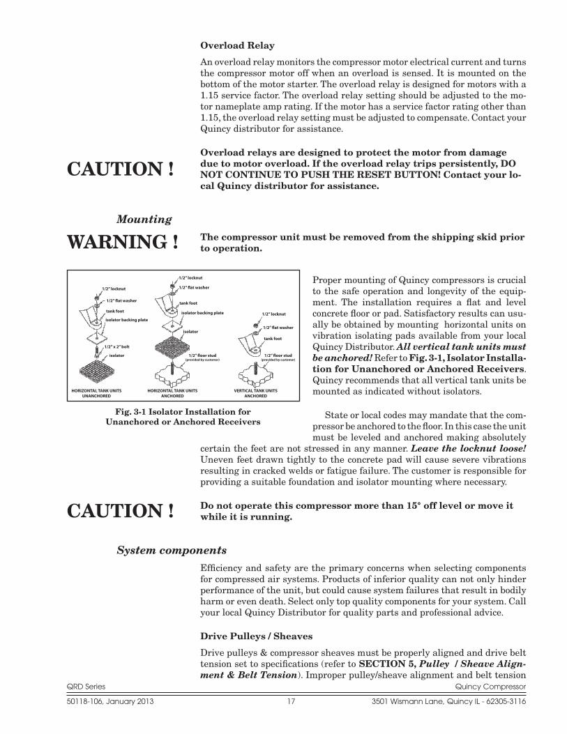
Proper mounting of Quincy compressors is crucial to the safe operation and longevity of the equip-ment. The installation requires a flat and level concrete floor or pad. Satisfactory results can usu-ally be obtained by mounting horizontal units on vibration isolating pads available from your local Quincy Distributor. All vertical tank units must be anchored! Refer to Fig. 3-1, Isolator Installa-tion for Unanchored or Anchored Receivers. Quincy recommends that all vertical tank units be mounted as indicated without isolators.
State or local codes may mandate that the com-pressor be anchored to the floor. In this case the unit must be leveled and anchored making absolutely
certain the feet are not stressed in any manner. Leave the locknut loose! Uneven feet drawn tightly to the concrete pad will cause severe vibrations resulting in cracked welds or fatigue failure. The customer is responsible for pro viding a suitable foundation and isolator mounting where necessary.
Do not operate this compressor more than 15° off level or move it while it is running.
System componentsEfficiency and safety are the primary concerns when selecting compo nents for compressed air systems. Products of inferior quality can not only hinder performance of the unit, but could cause system failures that result in bodily harm or even death. Select only top quality compo nents for your system. Call your local Quincy Distributor for quality parts and professional advice.
Drive Pulleys / Sheaves
Drive pulleys & com pressor sheaves must be properly aligned and drive belt tension set to specifica tions (refer to SECTION 5, Pulley / Sheave Align-ment & Belt Tension). Improper pulley/sheave alignment and belt ten sion
HORIZONTAL TANK UNITSANCHORED
VERTICAL TANK UNITSANCHORED
HORIZONTAL TANK UNITSUNANCHORED
1/2” locknut
1/2” �at washer
tank foot
isolator backing plate
1/2” x 2” bolt
isolator
1/2” locknut
1/2” �at washer
tank foot
isolator backing plate
isolator
1/2” �oor stud(provided by customer)
1/2” �oor stud(provided by customer)
tank foot
1/2” locknut
1/2” �at washer
Fig. 3-1 Isolator Installation for Unanchored or Anchored Receivers
CAUTION !
WARNING !
CAUTION !
QRD Series Quincy Compressor
50118-106, January 2013 18 3501 Wismann Lane, Quincy IL - 62305-3116
can cause motor overloading, excessive vibration, and prema ture belt and/or bearing failure.
Excessive compressor RPM’s (speed) could cause a pulley or sheave to shatter. In an instant, the pulley or sheave could separate into fragments capable of penetrating the belt guard and causing bodily harm or death. Do not operate the compressor above the recom-mended RPM (refer to SECTION 2, Specifications).
Guards
The QRD is equipped with a high air flow fan built into the compressor sheave capable of creating air flow of 5400 CFM at maximum speed. This and all mechanical action or motion is hazardous in varying degrees and needs to be guarded. Guards should be designed to achieve the required degree of protec-tion and still allow full air flow from the compressor sheave across the unit. Any restriction of the fan air flow will cause higher operating temperatures and reduce the service life of the compressor. Guards shall be in compliance with OSHA safety and health standards 29 CFR 1910.219 in OSHA manual 2206 and any state or local codes.
Guards must be fastened in place before starting the compressor and never removed before shutting off and locking out the main power supply.
Check Valves
Check valves are designed to prevent back-flow of air pressure in the com-pressed air system (air flows freely in one direction only). The check valve must be properly sized for air flow and tempera ture. Do not rely upon a check valve to isolate a compressor from a pressurized tank or compressed air delivery system during main tenance procedures!
Manual Shutoff Valves
Manual shutoff valves block the flow of air pressure in either direction. This type of valve can be used to isolate a compressor from a pressurized system, provided the system is equipped with a pressure relief valve ca pable of being manually released. The pressure relief valve should be installed between the manual shutoff valve and the compressor (refer to Fig. 3-2, Typical Drop Leg & Component Location).
Pressure Relief Valves
Pressure relief valves aid in preventing system failures by relieving system pressure when compressed air reaches a determined level. They are available in various pressure settings to accommodate a range of applications. Pressure relief valves are preset by the manufacturer and under no circumstances should the setting be changed by anyone other than the manufacturer.
Pressure relief valves are designed to protect compressed air systems in accordance with ASME B19 safety standards. Failure to provide properly sized pressure relief valves may cause property damage, severe personal injury or even death.
WARNING !
WARNING !
DANGER !
QRD Series Quincy Compressor
50118-106, January 2013 19 3501 Wismann Lane, Quincy IL - 62305-3116
Induction SystemAir Intake
A clean, cool and dry air supply is essential to the satisfactory operation of your Quincy air compressor. The standard air filter that the com pressor is equipped with when leaving the factory is of sufficient size and design to meet normal conditions, when properly serviced, in ac cordance with the maintenance sec-tion of this manual.
If however, the compressor is to be installed in a location where consid-erable dust, dirt and other contaminants are prevalent, consult your local Quincy distributor for advice and optional filters. A condensate trap must be installed as close as possible to the inlet filter if, as a result of installation or environmental conditions, there is any risk of moisture forming in the inlet piping. It is the user’s responsibility to provide adequate filtration for those conditions. Oil bath filters are not to be used. Warranty will be voided if a failure is determined to be caused by inadequate filtration.
Remote Inlet Filters
Depending on the size of the compressor and the size and construction of the room in which the unit operates, the air inlet may have to be located outside of the room. If it is necessary to remotely install the air filter, make the inlet piping as short and direct as possible. Remotely in stalled air filters can lead to vibrations in the inlet piping. These vibra tions can be minimized by adding a pulsation dampener or flex hose in the inlet piping between the remote inlet filter(s) and the compressor.
If the intake is piped to outside atmosphere, a hooded filter should be installed to prevent water or snow from being ingested into the compres sor.
All inlet piping should be at least the same size (or larger) in di ame ter as the inlet connection to the compressor. For every 10 feet of inlet piping or every 90° bend, increase the inlet piping diameter by one pipe size. The inlet piping must be thoroughly clean inside. Warranty may be voided if a failure results from incorrectly sized or improperly installed piping. Consult your local Quincy distributor for expert advice about installing Quincy QRD series compressors.
If an inlet manifold is required, the pipe diameter of the manifold must be large enough to limit the pressure drop in the inlet piping to less than 3 inches of water. Excessive pressure drop in the inlet will significantly affect the compressor’s performance and life.
Never locate the compressor air inlet system where toxic, volatile or corrosive vapors, air temperatures exceeding 100°F, water, or extremely dirty air could be ingested. These types of at mospheres could adversely affect the performance of the compres sor system.
Compressed Air Discharge SystemThe discharge piping should be of the same diameter as the compressor discharge connection, or sized so that the pressure drop at any point in the system does not exceed 10% of the air receiver pressure. Install aux iliary air receivers near heavy loads or at the far end of a long system. This will insure
CAUTION !

QRD Series Quincy Compressor
50118-106, January 2013 20 3501 Wismann Lane, Quincy IL - 62305-3116
sufficient pressure if the use is intermittent, or sudden large demands are placed on the system.
The compressed air supply line from the air receiver of stationary unit must be equipped with a properly rated flexible connection. Discharge piping
should slope to a drop leg (refer to Fig. 3-2, Typical Drop Leg & Component Location) or moisture trap to pro vide a collec-tion point where moisture can be easily removed. All service line outlets should be installed above the moisture traps to prevent moisture from entering the tool or device using the air. Manual shutoff valves, protected by pres-sure relief valves, should be installed at all service line outlets to eliminate leakage while the tools are not in use.
As with any piping, all parts of the discharge pip-ing should fit so as not to
create any stress between the piping and components.
Pneumatic Circuit Breakers or Velocity Fuses
The Occupational Safety and Health Act (OSHA), Section 1926.303, Paragraph 7, published in the Code of Federal Regulations 29 CFR 1920.1, revised July 1, 1982 states that all hoses exceeding 1/2” inside diameter shall have a safety device at the source of supply or branch line to reduce pressure in case of a hose failure”
These pneumatic safety devices are designed to prevent hoses from whip-ping and/or the loss of hazardous or toxic gasses, all of which could result in a serious or fatal accident.
Do not use plastic pipe, rubber hose, or lead-tin soldered joints in any part of the compressed air system.
Pressure Vessels
Air receiver tanks and other pressure containing vessels such as (but not limited to) pulsation bottles, heat exchangers, moisture separators and traps, must be in accordance with ASME Boiler and Pressure Vessel Code Section VIII and ANSI B19.3 safety stan dards. They must be equipped with a pressure relief valve, pressure gauge, tank drain, & manual shutoff valve (refer to Fig. 3-2, Typical Drop Leg & Component Location).
WARNING !
Fig. 3-2 Typical Drop Leg & Component Location
QRD Series Quincy Compressor
50118-106, January 2013 21 3501 Wismann Lane, Quincy IL - 62305-3116
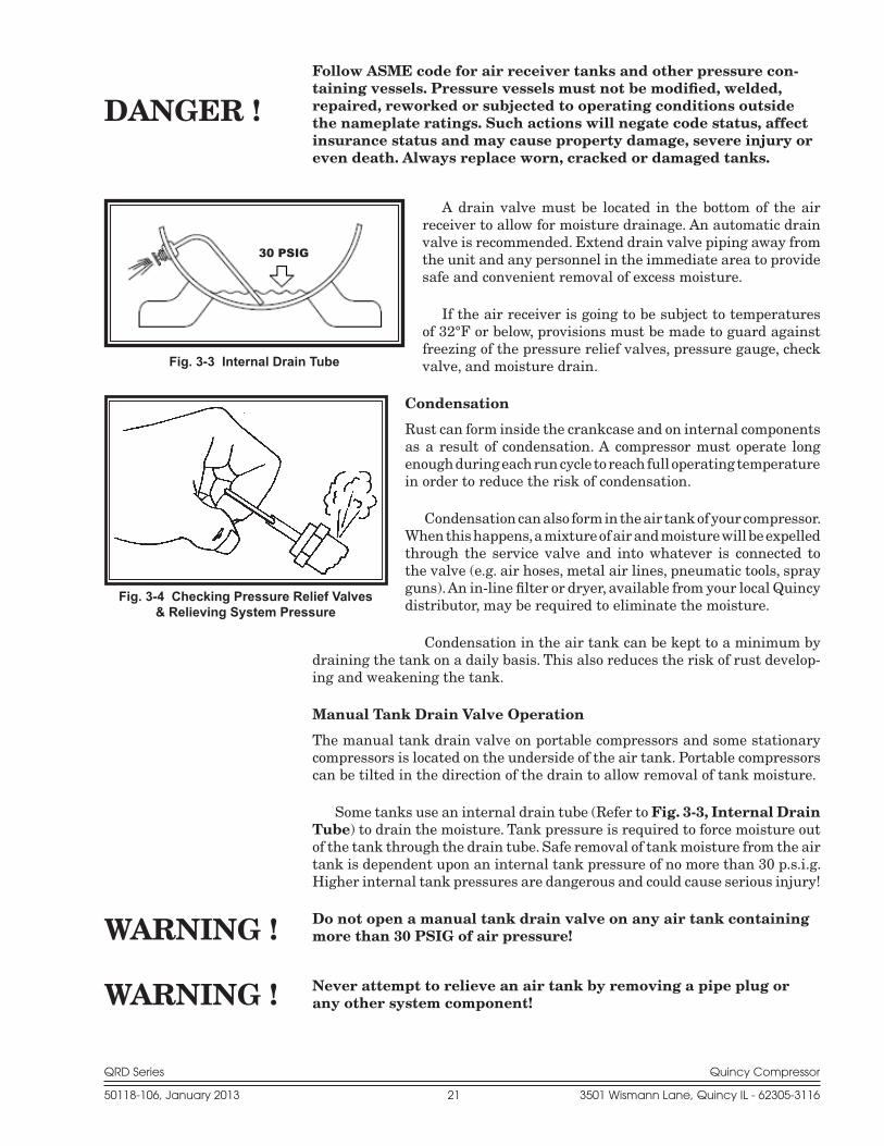
Follow ASME code for air receiver tanks and other pressure con-taining vessels. Pressure vessels must not be modified, welded, repaired, reworked or subjected to operating conditions outside the nameplate ratings. Such actions will negate code status, affect insurance status and may cause property damage, severe injury or even death. Always replace worn, cracked or damaged tanks.
A drain valve must be located in the bottom of the air receiver to allow for moisture drainage. An auto matic drain valve is recommended. Extend drain valve piping away from the unit and any personnel in the immediate area to provide safe and convenient removal of excess moisture.
If the air receiver is going to be subject to temperatures of 32°F or below, provisions must be made to guard against freezing of the pressure relief valves, pressure gauge, check valve, and moisture drain.
Condensation
Rust can form inside the crankcase and on internal com ponents as a result of condensation. A compressor must operate long enough during each run cycle to reach full operating temperature in order to reduce the risk of condensation.
Condensation can also form in the air tank of your com pressor. When this happens, a mixture of air and mois ture will be expelled through the service valve and into what ever is connected to the valve (e.g. air hoses, metal air lines, pneumatic tools, spray guns). An in-line filter or dryer, available from your local Quincy distributor, may be re quired to eliminate the moisture.
Condensation in the air tank can be kept to a mini mum by draining the tank on a daily basis. This also reduces the risk of rust develop-ing and weak ening the tank.
Manual Tank Drain Valve Operation
The manual tank drain valve on portable compressors and some stationary compressors is located on the underside of the air tank. Portable compressors can be tilted in the direction of the drain to allow removal of tank moisture.
Some tanks use an internal drain tube (Refer to Fig. 3-3, Internal Drain Tube) to drain the moisture. Tank pressure is required to force moisture out of the tank through the drain tube. Safe removal of tank moisture from the air tank is dependent upon an internal tank pressure of no more than 30 p.s.i.g. Higher internal tank pressures are dangerous and could cause serious injury!
Do not open a manual tank drain valve on any air tank containing more than 30 PSIG of air pressure!
Never attempt to relieve an air tank by removing a pipe plug or any other system component!
Fig. 3-4 Checking Pressure Relief Valves& Relieving System Pressure
Fig. 3-3 Internal Drain Tube
30 PSIG
DANGER !
WARNING !
WARNING !

QRD Series Quincy Compressor
50118-106, January 2013 22 3501 Wismann Lane, Quincy IL - 62305-3116
Manually Draining An Air Tank:
Step 1) Disconnect & lockout the compressor from the power source (elec-tric models) or disconnect the spark plug wire from the spark plug (gas engine models).
Step 2) Tank(s) subjected to freezing temperatures may contain ice. Store the compressor in a heated area before attempting to drain mois-ture from the tank(s). Reduce the air pressure in the tank to 30 p.s.i.g. by pulling the pressure relief valve ring (refer to Fig. 3-4, Checking Pressure Relief Valves & Relieving System Pres-sure).
Step 3) Slowly open the drain valve and allow the moisture and air mixture to drain from the tank.
Step 4) Once the moisture has been completely drained, close the drain valve.
Air Tank Inspection
Quincy Compressor recommends that all air tanks be inspected at scheduled inter-vals. Refer to Fig. 3-5 Recommended Air Tank Inspection Intervals for relative information. Measure tank wall thickness at several locations, including the lowest point where condensation can accumulate.
Refer to federal, state or provincial, or local codes for mandatory air tank maintenance information.
Tank Capacity
Horizontalor
Vertical
Minimum AllowableWall Thickness Visually
InspectHydrostatically
InspectHead Shell
30 Gal. Horizontal .094 .106 Yearly 10 Years30 Gal. Vertical .109 .111 Yearly 10 Years60 Gal. Horizontal .109 .135 Yearly 10 Years60 Gal. Vertical .109 .111 Yearly 10 Years80 Gal. Horizontal .109 .135 Yearly 10 Years80 Gal. Vertical .131 .133 Yearly 10 Years120 Gal. Horizontal .131 .162 Yearly 10 Years120 Gal. Vertical .163 .199 Yearly 10 Years200 Gal. Horizontal .163 .199 Yearly 10 Years240 Gal. Horizontal .163 .199 Yearly 10 Years
Fig. 3-5 Recommended Air Tank Inspection Intervals
QRD Series Quincy Compressor
50118-106, January 2013 23 3501 Wismann Lane, Quincy IL - 62305-3116
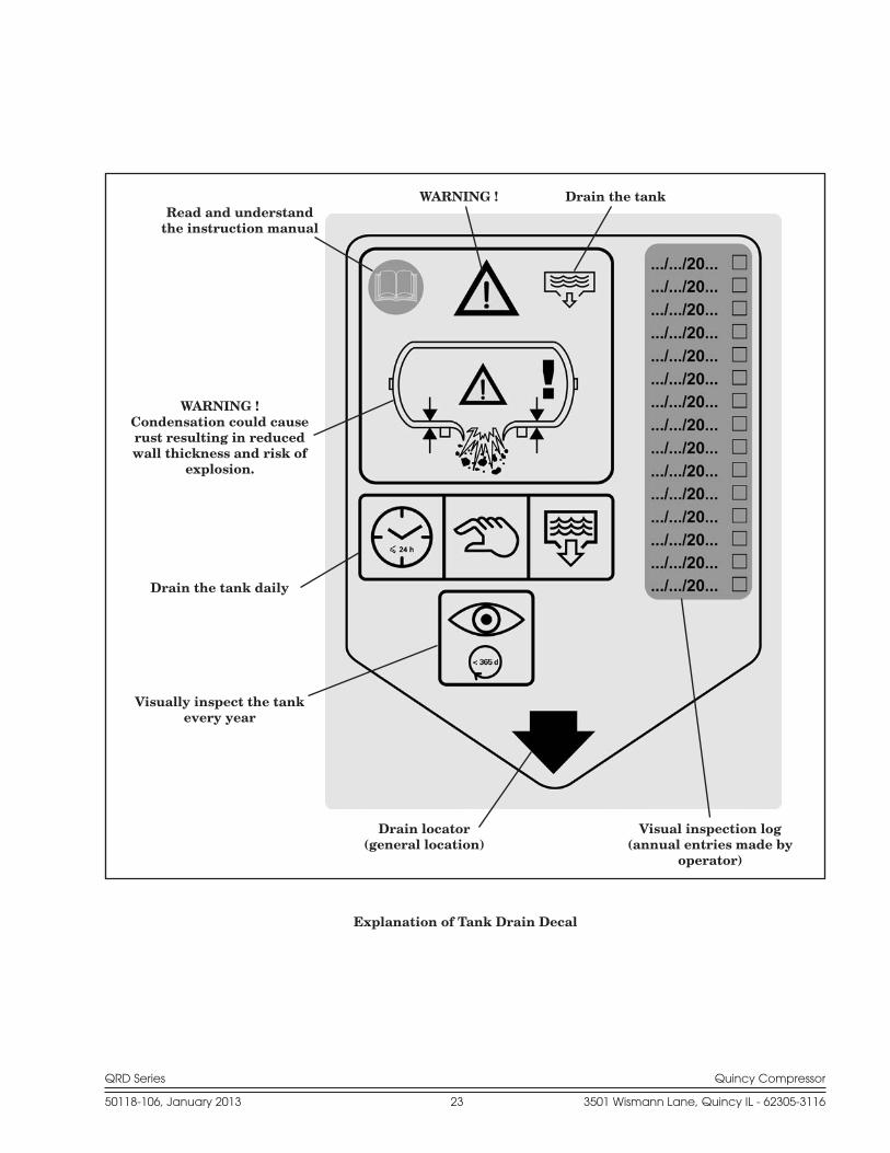
Explanation of Tank Drain Decal
Read and understandthe instruction manual
WARNING ! Drain the tank
WARNING !Condensation could cause rust resulting in reduced wall thickness and risk of
explosion.
Drain the tank daily
Visually inspect the tank every year
Drain locator(general location)
Visual inspection log(annual entries made by
operator)

QRD Series Quincy Compressor
50118-106, January 2013 24 3501 Wismann Lane, Quincy IL - 62305-3116
SECTION 4 START-UP & OPERATION
Pre-starting ChecklistNever assume a compressor is safe to work on just because it is not operating. It could restart at any time. Follow all safety precau-tions outlined in SECTION 5, Stopping For Maintenance.
Failure to perform the pre-starting checklist may result in me-chanical failure, property damage, serious injury or even death.
Steps 1 through 12 should be performed prior to connecting the unit to a power source. If any condition of the checklist is not satisfied, make the necessary adjustments or corrections before starting the compressor.
Step 1) Remove all installation tools from the compressor and check for installation debris.
Step 2) Check motor pulley and compressor sheaves for alignment and tightness on shaft. (Refer to SECTION 5, Pulley / Sheave Align-ment & Belt Tension.)
Step 3) Manually rotate the compressor sheave several rotations to be sure there are no mechanical interferences.
Step 4) Check inlet piping installation (Refer to SECTION 3, Induction System.)
Step 5) Check belt tension. (Refer to SECTION 5, Pulley / Sheave Alignment & Belt Tension.)
Step 6) Check all pressure connections for tightness.
Step 7) Make sure all pressure relief valves are correctly in stalled. (Refer to SECTION 3, System Components.)
Step 8) Be sure all guards are in place and securely mounted. (Refer to SECTION 3, System Components.)
Step 9) Check fuses, circuit breakers, and overload relays for proper size. (Refer to SECTION 3, Electrical Supply Requirements.)
Step 10) Open all manual shutoff valves at and beyond the compres sor discharge.
Step 11) After all the above conditions have been satisfied, the unit can be connected to the proper power source.
Step 12) Jog the starter switch to check the rotational direction of the compressor. It should agree with the rotation arrow em bossed on the compressor sheave.
WARNING !
WARNING !

QRD Series Quincy Compressor
50118-106, January 2013 25 3501 Wismann Lane, Quincy IL - 62305-3116
Step 13) Check for proper rotation of the cylinder cooling fan (fins inside sheave). The fan should blow cooling air across the cylinder.
Initial Starting & OperatingThis instruction manual, as well as any instructions supplied by manufacturers of supporting equipment, should be read and un derstood prior to starting the compressor. If there are any questions regarding any part of the instructions, please call your local Quincy distributor, or the Quincy Compressor factory.
With the pre-starting checklist completed and satisfied, start the compres-sor. Watch and listen for excessive vibration and strange noises. If either ex-ist, stop the compressor. Refer to SECTION 6, Troubleshooting for help in determining the cause of such prob lems.
Check the air receiver pressure gauge or system pressure gauges for proper readings. If inadequate or excessive air pressure condi tions exist, refer to Section 6 Troubleshooting.
Heat created during the initial startup of a new compressor will cause slight expansion of the head(s). This slight expansion crushes the head gasket ever so slightly and affects the torque value of the cylinder fasteners (capscrews). To ensure optimal performance, Quincy recommends that you initially oper-ate the compressor for at least one hour. Shut the compressor off and follow precautions outlined in SECTION 5, Stopping for Maintenance. Retorque the cylinder to head capscrews to the specifications outlined in the parts book corresponding to the Record of Change for your compressor after the compres-sor has cooled.
Observe compressor operation closely for the first hour of opera tion and then frequently for the next seven hours. After the first eight hours, monitor the compressor at least once every eight hours. Check all pressurized compo-nents for rust, cracks or leaks. Immediately discontinue use of equipment and relieve all system pressure if any of these problems are discovered. Do not use the equipment until it has been repaired by a qualified mechanic. After two days of operation check belt tension, and inspect the system for leaks.
Important Operating InstructionsIt is important that your QRD air compressor reaches proper operating
temperatures while it is running. Failure to do so will result in unwanted moisture in the internal components. To reach these operating temperatures a minimum run time cycle should be established. This cycle should be re-viewed with your local Quincy Compressor distributor, or contact the Quincy Compressor factory in Quincy, Illinois at 217-222-7700 and ask for the Service Department.
Daily Starting ChecklistDo not proceed until the Pre-starting Checklist and Initial Starting & Operating subsections have been read and are thor oughly understood.
Step 1) Drain liquid from the air receiver (if so equipped).
QRD Series Quincy Compressor
50118-106, January 2013 26 3501 Wismann Lane, Quincy IL - 62305-3116
Step 2) Check all hoses and fittings for weak or worn conditions and re-place if necessary.
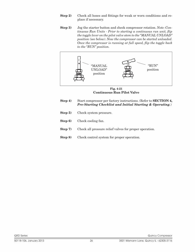
Step 3) Jog the starter button and check compressor rotation. Note: Con-tinuous Run Units - Prior to starting a continuous run unit, flip the toggle lever on the pilot valve stem to the “MANUAL UNLOAD” position (see below). Now the compressor can be started unloaded. Once the compressor is running at full speed, flip the toggle back to the “RUN” position.
Step 4) Start compressor per factory instructions. (Refer to SECTION 4, Pre-Starting Checklist and Initial Starting & Operating.)
Step 5) Check system pressure.
Step 6) Check cooling fan.
Step 7) Check all pressure relief valves for proper operation.
Step 8) Check control system for proper operation.
“MANUALUNLOAD”
position
“RUN”position
Fig. 4-21Continuous Run Pilot Valve
QRD Series Quincy Compressor
50118-106, January 2013 27 3501 Wismann Lane, Quincy IL - 62305-3116
SECTION 5 MAINTENANCE
Stopping for MaintenanceThe following procedures should be followed when stopping the com pressor for maintenance or service:
Step 1) Per OSHA regulation 1910.147: The Control of Hazardous Energy Source (Lockout/Tagout), disconnect and lockout the main power source. Display a sign in clear view at the main power switch stat-ing that the compressor is being serviced.
Never assume a compressor is safe to work on just because it is not operating. It could restart at any time.
Step 2) Isolate the compressor from the compressed air supply by closing a manual shutoff valve upstream and downstream from the com-pressor. Display a sign in clear view at the shutoff valve stating that the compressor is being serviced.
Step 3) Open a pressure relief valve within the pressurized system to al-low it to be completely de-pressurized. NEVER remove a plug to relieve the pressure!
Step 4) Open all manual drain valves within the area to be serviced.
Step 5) Wait for the unit to cool before starting to service. (Temperatures of 125°F can burn skin. Some surface tem pera tures exceed 350°F when the compressor is operating.)
Maintenance ScheduleTo assure maximum performance and service life of your compres sor, a routine maintenance schedule should be developed. A sample schedule has been in-cluded here showing suggested maintenance intervals, to help you to develop a mainte nance schedule designed for your particular application. Time frames may need to be shortened in harsher environments.
At the back of this instruction manual you will find a Maintenance Sched-ule Checklist. Make copies of this checklist and retain the master to make more copies as needed. On a copy of the checklist, enter dates and initials in the appropriate spaces. Keep the checklist and this Instruction Manual readily available near the compressor.
Scheduled maintenance intervals are rated for continuous duty operation at maximum pressure capability of the compressor. The service interval can vary with duty cycle, speed and operating pressure.
WARNING !
QRD Series Quincy Compressor
50118-106, January 2013 28 3501 Wismann Lane, Quincy IL - 62305-3116
†
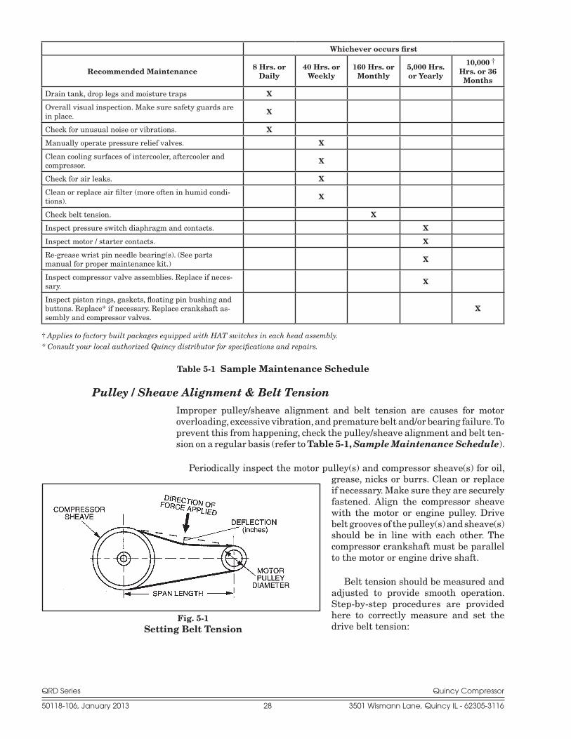
Pulley / Sheave Alignment & Belt TensionImproper pulley/sheave alignment and belt tension are causes for mo tor overloading, excessive vibration, and premature belt and/or bearing failure. To prevent this from happening, check the pulley/sheave alignment and belt ten-sion on a regular basis (refer to Table 5-1, Sample Maintenance Schedule).
Periodically inspect the motor pulley(s) and compressor sheave(s) for oil, grease, nicks or burrs. Clean or replace if necessary. Make sure they are securely fastened. Align the compressor sheave with the motor or engine pulley. Drive belt grooves of the pulley(s) and sheave(s) should be in line with each other. The compressor crankshaft must be parallel to the motor or engine drive shaft.
Belt tension should be measured and adjusted to provide smooth op eration. Step-by-step procedures are provided here to correctly measure and set the drive belt tension:
Whichever occurs first
Recommended Maintenance 8 Hrs. or Daily
40 Hrs. or Weekly
160 Hrs. or Monthly
5,000 Hrs. or Yearly
10,000 Hrs. or 36 Months
Drain tank, drop legs and moisture traps X
Overall visual inspection. Make sure safety guards are in place. X
Check for unusual noise or vibrations. X
Manually operate pressure relief valves. X
Clean cooling surfaces of intercooler, aftercooler and compressor. X
Check for air leaks. X
Clean or replace air filter (more often in humid condi-tions). X
Check belt tension. X
Inspect pressure switch diaphragm and contacts. X
Inspect motor / starter contacts. X
Re-grease wrist pin needle bearing(s). (See parts manual for proper maintenance kit.) X
Inspect compressor valve assemblies. Replace if neces-sary. X
Inspect piston rings, gaskets, floating pin bushing and buttons. Replace* if necessary. Replace crankshaft as-sembly and compressor valves.
X
Fig. 5-1 Setting Belt Tension
† Applies to factory built packages equipped with HAT switches in each head assembly.* Consult your local authorized Quincy distributor for specifications and repairs.
Table 5-1 Sample Maintenance Schedule
QRD Series Quincy Compressor
50118-106, January 2013 29 3501 Wismann Lane, Quincy IL - 62305-3116
Step 1) Measure the span length of the drive. (Refer to Fig. 5-1, Setting Belt Tension.)
Recommended Belt Motor Pulley Deflection Force (lbs.) Cross Dia. Range Initial Retensioning Section (inches) Installation Min. Max.
up to 4.6 7.3 4.9 6.4 B 4.7 - 5.6 8.7 5.8 7.5 5.7 - 7.0 9.3 6.2 8.1 7.1 + above 10.0 6.8 8.8
Step 2) Determine the amount of deflection (in inches) required to mea-sure de flection force (in pounds) by multi plying the span length x 1/64 (.016) (i.e. 32” span length x 1/64 [.016] = 1/2”[.50] of deflection required to measure de flection force).
Step 3) Lay a straightedge across the top outer surface of a drive belt from pulley to sheave.
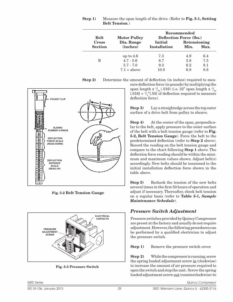
Step 4) At the center of the span, perpendicu-lar to the belt, apply pressure to the outer surface of the belt with a belt tension gauge (refer to Fig. 5-2, Belt Tension Gauge). Force the belt to the predetermined deflection (refer to Step 2 above). Record the reading on the belt tension gauge and compare to the chart following Step 1 above. The de flection force reading should be within the mini-mum and maximum values shown. Adjust belt(s) accord ingly. New belts should be tensioned to the initial installation deflection force shown in the table above.
Step 5) Recheck the tension of the new belts several times in the first 50 hours of operation and adjust if necessary. Thereafter, check belt tension on a regular basis (refer to Table 5-1, Sample Maintenance Schedule).
Pressure Switch AdjustmentPressure switches provided by Quincy Compressor are preset at the factory and usu ally do not require adjustment. However, the following procedures can be performed by a qualified electrician to adjust the pressure switch.
Step 1) Remove the pressure switch cover.
Step 2) While the compressor is running, screw the spring loaded adjustment screw in (clockwise) to increase the amount of air pressure required to open the switch and stop the unit. Screw the spring loaded adjustment screw out (counterclockwise) to
Fig. 5-2 Belt Tension Gauge
Fig. 5-3 Pressure Switch
PRESSURE ADJUSTMENT
SCREW
ELECTRICAL CONTACTS
POCKET CLIP
SLIDING RUBBER O-RINGS
DEFLECTION FORCE SCALE(READ DOWN)
DEFLECTION DISTANCE
SCALE(READ UP)

QRD Series Quincy Compressor
50118-106, January 2013 30 3501 Wismann Lane, Quincy IL - 62305-3116
decrease the amount of air pressure required to open the switch and stop the unit.
Standard pressure switches supplied by Quincy Compressor are equipped with a fixed 20 PSIG (approx.) differential. Optional switches include both pressure and differen tial adjustment capabili ties.
Electric power always exists inside the pressure switch whenever the compressor package is connected to a power supply. Be careful not to touch any electrical leads when setting the pres sure switch.
Never exceed the designed pressure for the system or overload the motor beyond its Maximum Amp Draw.
* Full Load Amps x Service Factor = Maximum Amp Draw
Never assume a compressor is safe to work on just because it is not operating. It may be in the automatic standby mode and may re-start any time. Follow all safety precautions outlined in SECTION 5, Stopping For Maintenance.
Torque Specifications
WARNING !
WARNING !
WARNING !
Wrist PinSetscrews
DischargeManifold
Bolts
Cylinderto
CrankcaseBolts
Headto
CylinderBolts
Head toValve
Plate Nut
BearingCarrier
Bolts
CompressorSheaveBolts
100 in.-lbs. 30 ft.-lbs. 30 ft.-lbs. 30 ft.-lbs. 25 ft.-lbs. 30 ft.-lbs. 75 ft.-lbs.
Table 5-4 Torque Specifications(specifications listed for dry threads only)
*Full Load Amps (FLA) & Service Factor can be found on the motor nameplate.
QRD Series Quincy Compressor
50118-106, January 2013 31 3501 Wismann Lane, Quincy IL - 62305-3116
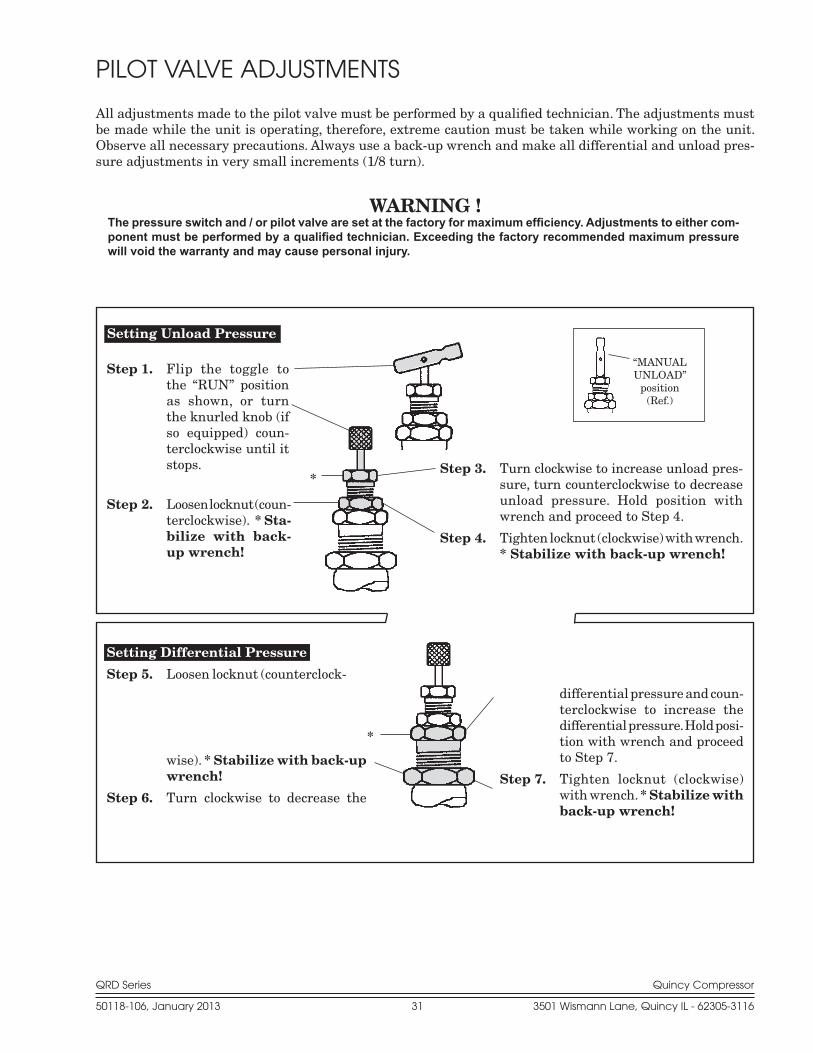
PILOT VALVE ADJUSTMENTS
All adjustments made to the pilot valve must be performed by a qualified technician. The adjustments must be made while the unit is operating, therefore, extreme caution must be taken while working on the unit. Observe all necessary precautions. Always use a back-up wrench and make all differential and unload pres-sure adjustments in very small increments (1/8 turn).
WARNING !The pressure switch and / or pilot valve are set at the factory for maximum efficiency. Adjustments to either com-ponent must be performed by a qualified technician. Exceeding the factory recommended maximum pressure will void the warranty and may cause personal injury.
*
Setting Unload Pressure
*
Step 1. Flip the toggle to the “RUN” position as shown, or turn the knurled knob (if so equipped) coun-terclockwise until it stops.
Step 2. Loosen locknut (coun-terclockwise). * Sta-bilize with back-up wrench!
Step 3. Turn clockwise to increase unload pres-sure, turn counterclockwise to decrease unload pressure. Hold position with wrench and proceed to Step 4.
Step 4. Tighten locknut (clockwise) with wrench. * Stabilize with back-up wrench!
Setting Differential Pressure
Step 5. Loosen locknut (counterclock-
wise). * Stabilize with back-up wrench!
Step 6. Turn clockwise to decrease the
differential pressure and coun-terclockwise to increase the differential pressure. Hold posi-tion with wrench and proceed to Step 7.
Step 7. Tighten locknut (clockwise) with wrench. * Stabilize with back-up wrench!
“MANUALUNLOAD”
position(Ref.)
QRD Series Quincy Compressor
50118-106, January 2013 32 3501 Wismann Lane, Quincy IL - 62305-3116
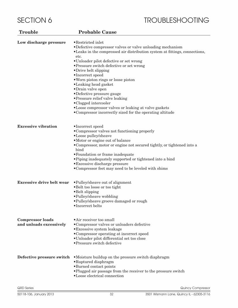
SECTION 6 TROUBLESHOOTING
Trouble Probable Cause
Low discharge pressure •Restricted inlet •Defective compressor valves or valve unloading mechanism •Leaks in the compressed air distribution system at fittings, connections, etc. •Unloader pilot defective or set wrong •Pressure switch defective or set wrong •Drive belt slipping •Incorrect speed •Worn piston rings or loose piston •Leaking head gasket •Drain valve open •Defective pressure gauge •Pressure relief valve leaking •Clogged intercooler •Loose compressor valves or leaking at valve gaskets •Compressor incorrectly sized for the operating alti tude
Excessive vibration •Incorrect speed •Compressor valves not functioning prop erly •Loose pulley/sheave •Motor or engine out of balance •Compressor, motor or engine not secured tightly, or tightened into a bind •Foundation or frame inadequate •Piping inadequately supported or tightened into a bind •Excessive discharge pressure •Compressor feet may need to be leveled with shims
Excessive drive belt wear •Pulley/sheave out of alignment •Belt too loose or too tight •Belt slipping •Pulley/sheave wobbling •Pulley/sheave groove damaged or rough •Incorrect belts
Compressor loads •Air receiver too smalland unloads excessively •Compressor valves or unloaders defective •Excessive system leakage •Compressor operating at incorrect speed •Unloader pilot differential set too close •Pressure switch defective
Defective pressure switch •Moisture buildup on the pressure switch diaphragm •Ruptured diaphragm •Burned contact points •Plugged air passage from the receiver to the pressure switch •Loose electrical connection
QRD Series Quincy Compressor
50118-106, January 2013 33 3501 Wismann Lane, Quincy IL - 62305-3116
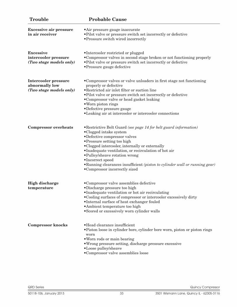
Trouble Probable Cause
Excessive air pressure •Air pressure gauge inaccuratein air receiver •Pilot valve or pressure switch set incor rectly or defective •Pressure switch wired incorrectly Excessive •Intercooler restricted or pluggedintercooler pressure •Compressor valves in second stage broken or not functioning properly(Two stage models only) •Pilot valve or pressure switch set incor rectly or defective •Pressure gauge defective Intercooler pressure •Compressor valves or valve unloaders in first stage not functioning abnormally low properly or defective(Two stage models only) •Restricted air inlet filter or suction line •Pilot valve or pressure switch set incor rectly or defective •Compressor valve or head gasket leaking •Worn piston rings •Defective pressure gauge •Leaking air at intercooler or intercooler connections
Compressor overheats •Restrictive Belt Guard (see page 14 for belt guard information) •Clogged intake system •Defective compressor valves •Pressure setting too high •Clogged intercooler, internally or exter nally •Inadequate ventilation, or recirculation of hot air •Pulley/sheave rotation wrong •Incorrect speed •Running clearances insufficient (piston to cylinder wall or running gear) •Compressor incorrectly sized
High discharge •Compressor valve assemblies defectivetemperature •Discharge pressure too high •Inadequate ventilation or hot air recirculat ing •Cooling surfaces of compressor or inter cooler excessively dirty •Internal surface of heat exchanger fouled •Ambient temperature too high •Scored or excessively worn cylinder walls
Compressor knocks •Head clearance insufficient •Piston loose in cylinder bore, cylinder bore worn, piston or piston rings worn •Worn rods or main bearing •Wrong pressure setting, discharge pressure excessive •Loose pulley/sheave •Compressor valve assemblies loose

QRD Series Quincy Compressor
50118-106, January 2013 34 3501 Wismann Lane, Quincy IL - 62305-3116
Overload relays are designed to pro-tect the motor from damage due to motor overload. If the overload relay trips persistently, DO NOT CONTIN-UE TO PUSH THE RESET BUTTON! Contact your local Quincy distribu-tor for assistance.
CAUTION !
Trouble Probable Cause
Excessive current draw •Low voltage (must be within 10% of name plate voltage) (To determine maximum •Loose electrical connectionamper age allowed, multiply •Wire size too smallthe FLA on the motor •Discharge pressure too highnameplate by the service •Intercooler pluggingfactor.) •Bearings tight or seizingCAUTION ! •Motor sized incorrectlyMotor surface temperature •Motor defectivenormally exceeds 170° F. •Drive belts too tight Failure to start •Power not on •Blown circuit fuse •Overload relay fuses tripped •Low voltage •Faulty start switch •Power failure •Pressure switch incorrectly adjusted or faulty •Loose or broken wire •Motor defective •Compressor seized
Motor stalls •Motor overloaded (refer to Excessive current draw)

QRD Series Quincy Compressor
50118-106, January 2013 35 3501 Wismann Lane, Quincy IL - 62305-3116
SECTION 7 REFERENCE INFORMATION
Approximate Capacity Correction for AltitudeCorrection Factors
Altitude Single Stage Two Stage (ft.) 25 PSIG 40 PSIG 60 PSIG 80 PSIG 90 PSIG 100 PSIG 100 PSIG 150 PSIG
Sea Level 1.00 1.00 1.00 1.00 1.00 1.00 1.00 1.00
1000 0.996 0.993 0.992 0.992 0.998 0.987 0.995 .993
2000 0.992 0.987 0.984 0.977 0.972 0.969 0.991 .987
3000 0.987 0.981 0.974 0.967 0.959 0.954 0.986 .981
4000 0.982 0.974 0.963 0.953 0.944 0.940 0.980 .974
5000 0.977 0.967 0.953 0.940 0.931 0.925 0.975 .967
6000 0.972 0.961 0.945 0.928 0.917 0.908 0.970 .961
7000 0.967 0.953 0.936 0.915 0.902 0.890 0.964 .953
8000 0.962 0.945 0.925 0.900 0.886 0.873 0.958 .945
9000 0.957 0.938 0.915 0.887 0.868 0.857 0.953 .938
10000 0.951 0.931 0.902 0.872 0.853 0.840 0.946 .931
11000 0.945 0.923 0.891 0.858 0.837 0.940 .923
12000 0.938 0.914 0.878 0.839 0.818 0.932 .914
14000 0.927 0.897 0.852 0.805 0.920 .897
15000 0.918 0.887 0.836 0.784 0.910 .887
Notes: 1.) Correction factors are approximate and shown for single stage com-
pressors and high pressure discharge on two stage compressors.
2.) This chart does not allow for air tools which require more free air at alti-tiudes above sea level.
3.) To find the capacity of a compressor at a given altitude, multiply the rated capacity of the compressor by the factor corresponding to the altitude and discharge pressure. The result will be the actual capacity (CFM) of the compressor at the given altitude.

QRD Series Quincy Compressor
50118-106, January 2013 36 3501 Wismann Lane, Quincy IL - 62305-3116
Typical Two Stage QRD Base Mounted Unit
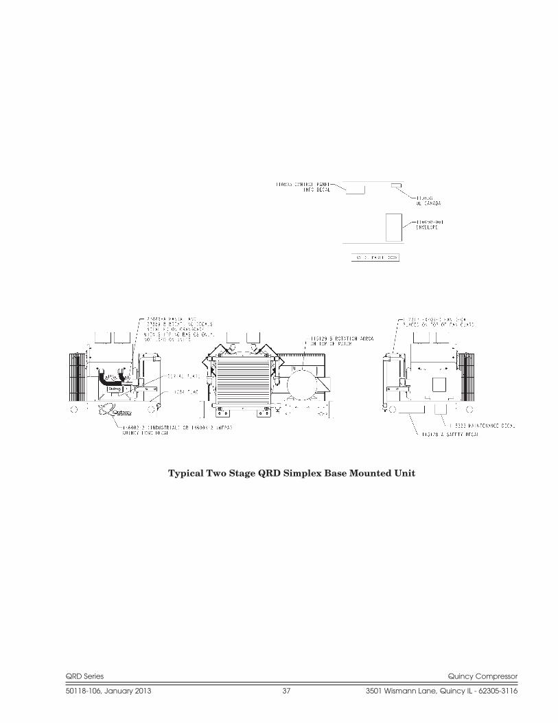
Decal Locations
QRD Series Quincy Compressor
50118-106, January 2013 37 3501 Wismann Lane, Quincy IL - 62305-3116
Typical Two Stage QRD Simplex Base Mounted Unit
QRD Series Quincy Compressor
50118-106, January 2013 38 3501 Wismann Lane, Quincy IL - 62305-3116
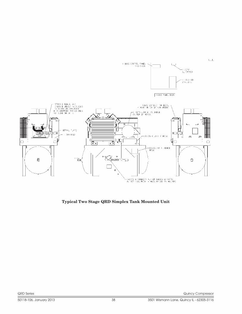
Typical Two Stage QRD Simplex Tank Mounted Unit

QRD Series Quincy Compressor
50118-106, January 2013 39 3501 Wismann Lane, Quincy IL - 62305-3116
QUINCY COMPRESSORSTANDARD TERMS AND CONDITIONS
LEGAL EFFECT: Except as expressly otherwise agreed to in writing by an authorized representative of Seller, the following terms and conditions shall apply to and form a part of this order and any additional and/or different terms of Buyer’s purchase order or other form of acceptance are rejected in advance and shall not become a part of this order.
The rights of Buyer hereunder shall be neither assignable nor transferable except with the written consent of Seller.
This order may not be canceled or altered except with the written consent of Seller and upon terms which will indemnify Seller against all loss oc-casioned thereby. All additional costs incurred by Seller due to changes in design or specifications, modification of this order or revision of product must be paid for by Buyer.
In addition to the rights and remedies conferred upon Seller by this order, Seller shall have all rights and remedies conferred at law and in equity and shall not be required to proceed with the performance of this order if Buyer is in default in the performance of such order or of any other contract or order with seller.
TERMS OF PAYMENT: Unless otherwise specified in the order acknowl-edgment, the terms of payment shall be 1% 15, net forty-five (45) days after shipment. These terms shall apply to partial as well as complete shipments. If any proceeding be initiated by or against Buyer under any bankruptcy or insolvency law, or in the judgment of Seller the financial condition of Buyer, at the time the equipment is ready for shipment, does not justify the terms of payment specified, Seller reserves the right to require full payment in cash prior to making shipment. If such payment is not received within fifteen (15) days after notification of readiness for shipment, Seller may cancel the order as to any unshipped item and require payment of its reasonable cancellation charges.
If Buyer delays shipment, payments based on date of shipment shall become due as of the date when ready for shipment. If Buyer delays completion of manufacture, Seller may elect to require payment according to percentage of completion. Equipment held for Buyer shall be at Buyer’s risk and storage charges may be applied at the discretion of Seller.
Accounts past due shall bare interest at the highest rate lawful to contract for but if there is no limit set by law, such interest shall be eighteen percent (18%). Buyer shall pay all cost and expenses, including reasonable attorney’s fees, incurred in collecting the same, and no claim, except claims within Seller’s warranty of material or workmanship, as stated below, will be recognized unless delivered in writing to Seller within thirty (30) days after date of shipment.
TAXES: All prices exclude present and future sales, use, occupation, license, excise, and other taxes in respect of manufacture, sales or delivery, all of which shall be paid by Buyer unless included in the purchase price at the proper rate or a proper exemption certificate is furnished.
ACCEPTANCE: All offers to purchase, quotations and contracts of sales are subject to final acceptance by an authorized representative at Seller’s plant.
DELIVERY: Except as otherwise specified in this quotation, delivery will be F. O. B. point of shipment. In the absence of exact shipping instruction, Seller will use its discretion regarding best means of insured shipment. No liability will be accepted by Seller for so doing. All transportation charges are at Buyer’s expense. Time of delivery is an estimate only and is based upon the receipt of all information and necessary approvals. The shipping schedule shall not be construed to limit seller in making commitments for materials or in fabricating articles under this order in accordance with Seller’s normal and reasonable production schedules.
Seller shall in no event be liable for delays caused by fires, acts of God, strikes, labor difficulties, acts of governmental or military authorities, delays in transportation or procuring materials, or causes of any kind beyond Seller’s control. No provision for liquidated damages for any cause shall apply under this order. Buyer shall accept delivery within thirty (30) days after receipt of notification of readiness for shipment. Claims for shortages will be deemed to have been waived if not made in writing with ten (10) days after the receipt of the material in respect of which any such shortage is claimed. Seller is not responsible for loss or damage in transit after having received “In Good Order” receipt from the carrier. All claims for loss or damage in transit should be made to the carrier.
TITLE & LIEN RIGHTS: The equipment shall remain personal property, regardless of how affixed to any realty or structure. Until the price (including any notes given therefore) of the equipment has been fully paid in cash, Seller shall, in the event of Buyer’s default, have the right to repossess such equipment.
PATENT INFRINGMENT: If properly notified and given an opportunity to do so with friendly assistance, Seller will defend Buyer and the ultimate user of the equipment from any actual or alleged infringement of any published United States patent by the equipment or any part thereof furnished pursu-ant hereto (other than parts of special design, construction, or manufacture specified by and originating with Buyer), and will pay all damages and costs awarded by competent court in any suit thus defended or of which it may have had notice and opportunity to defend as aforesaid.
STANDARD WARRANTY: Seller warrants that products of its own manufacture will be free from defects in workmanship and materials under normal use and service for the period specified in the product instruction manual. Warranty for service parts will be Ninety (90) days from date of factory shipment. Electric Motors, gasoline and diesel engines, electrical ap-paratus and all other accessories, components and parts not manufactured by Seller are warranted only to the extent of the original manufacturer’s warranty.
Notice of the alleged defect must be given to the Seller, in writing with all identifying details including serial number, type of equipment and date of purchase within thirty (30) days of the discovery of the same during the warranty period.
Seller’s sole obligation on this warranty shall be, at its option, to repair or replace or refund the purchase price of any product or part thereof which proves to be defective. If requested by Seller, such product or part thereof must be promptly returned to seller, freight prepaid, for inspection.
Seller warrants repaired or replaced parts of its own manufacture against defects in materials and workmanship under normal use and service for ninety (90) days or for the remainder of the warranty on the product being repaired.
This warranty shall not apply and Seller shall not be responsible or liable for:(a) Consequential, collateral or special losses or damages;(b) Equipment conditions caused by fair wear and tear, abnormal
conditions of use, accident, neglect or misuse of equipment, improper storage or damage resulting during shipping;
(c) Deviation from operating instructions, specifications or other special terms of sale;
(d) Labor charges, loss or damage resulting from improper opera-tion, maintenance or repairs made by person(s) other than Seller or Seller’s authorized service station.
In no event shall Seller be liable for any claims whether arising from breach of contract or warranty or claims of negligence or negligent manufacture in excess of the purchase price.
THIS WARRANTY IS THE SOLE WARRANTY OF SELLERS AND ANY OTHER WARRANTIES, WHETHER EXPRESS OR IMPLIED IN LAW OR IMPLIED IN FACT, INCLUDING ANY WARRANTIES OF MERCHANTABILITY AND FITNESS FOR PARTICULAR USE ARE HEREBY SPECIFICALLY EXCLUDED.
LIABILITY LIMITATIONS: Under no circumstances shall the Seller have any liability for liquidated damages or for collateral, consequential or special damages or for loss of profits, or for actual losses or for loss of production or progress of construction, whether resulting from delays in delivery or perfor-mance, breach of warranty, negligent manufacture or otherwise.
ENVIROMENTAL AND OSHA REQUIREMENTS: At the time of ship-ment of the equipment from the factory, Quincy Compressor / Ortman Fluid Power will comply with the various Federal, State and local laws and regula-tions concerning occupational health and safety and pollution. However, in the installation and operation of the equipment and other matters over which the seller has no control, the Seller assumes no responsibility for compliance with those laws and regulations, whether by the way of indemnity, warranty or otherwise.
June 30, 2003

Reciprocating / Systems: 217.222.7700
Air Master 217.277.0270
E-mail: [email protected]
Website: quincycompressor.com