Embed Size (px)
Citation preview
R&M Materials Handling, Inc LoadMate® Chain Hoist Springfield, Ohio USA QL Crane Assembly Instructions : 800 955-9967 Single Girder Top Running www.rmhoist.com November 2004
Bulletin: RM-QL-CA-SGTR-1H-2002-1-ENG.doc
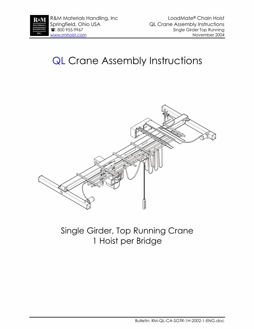
QL Crane Assembly Instructions
Single Girder, Top Running Crane 1 Hoist per Bridge
R&M Materials Handling, Inc LoadMate® Chain Hoist Springfield, Ohio USA QL Crane Assembly Instructions : 800 955-9967 Single Girder Top Running www.rmhoist.com November 2004
11/02/04 RM-QL-CA-SGTR-1H-2002-1-ENG.doc 2
The QL Crane Assembly instructions have been prepared to acquaint you with the procedures necessary for assembly of the supplied crane components. In addition to the QL Crane Assembly instructions, the following manuals are also included in the modular crane package:
Installation and Maintenance Manual for the chain hoist Operator’s manual for the chain hoist Installation, Operation and Maintenance Instructions for the TMU Motorized Trolley Installation and Maintenance Manual for the bridge drives Chain hoist wiring diagrams for crane applications Electrical Bill of Material for the crane controls
Proper installation is important to the performance of the equipment. Careful study of and adherence to the instructions will help ensure safe, dependable operation. It is also recommended that you keep the manuals for the equipment readily accessible to operators as well as maintenance and safety personnel. Information in this manual is subject to change without notice. R&M Materials Handling, Inc 4501 Gateway Boulevard Springfield, Ohio USA Phone: 800 955-9967 Fax: 800 955-5162 Visit us on the web: www.rmhoist.com
R&M Materials Handling, Inc LoadMate® Chain Hoist Springfield, Ohio USA QL Crane Assembly Instructions : 800 955-9967 Single Girder Top Running www.rmhoist.com November 2004
11/02/04 RM-QL-CA-SGTR-1H-2002-1-ENG.doc 3
CONTENTS
General .........................................................................................................................................4 Power Connections.......................................................................................................................4 Bridge Beam .................................................................................................................................5 Beam Connection .........................................................................................................................5 Main Crane Components ..............................................................................................................6 Layout of Festoon Rails (Old Style) ..............................................................................................8 Layout of Festoon Rails (New Style)...........................................................................................10 Hoist Tow Arm Assembly............................................................................................................12 Bridge Drive Assembly................................................................................................................12 Trolley End Stop Assembly.........................................................................................................13 Bridge Panel Support Assembly (Old Style) ...............................................................................14 Bridge Panel Support Assembly (New Style)..............................................................................16 Festoon Assembly ......................................................................................................................18 Tow Arm Assembly for Crane (Old Style) ...................................................................................20 Tow Arm Assembly for Crane (New Style) .................................................................................21 Bridge Travel Limit Switch ..........................................................................................................22 Bridge Travel Limit Switch Mounting (New Style) .......................................................................23 Horn Location & Mounting (New Style).......................................................................................23 Radio Receiver Mounting (New Style) ........................................................................................23 Plug Identification and Layout.....................................................................................................24 Operational Tests........................................................................................................................26

R&M Materials Handling, Inc LoadMate® Chain Hoist Springfield, Ohio USA QL Crane Assembly Instructions : 800 955-9967 Single Girder Top Running www.rmhoist.com November 2004
11/02/04 RM-QL-CA-SGTR-1H-2002-1-ENG.doc 4
General A QL Modular Crane Package includes:
LoadMate® electric chain hoist End trucks including joint plates Bridge drives Bridge panel with cable plugs Complete festoon package featuring plugs for quick connections Festoon tow arm for hoist Bridge tow arm for main power Bridge travel limit switch Trolley end stops Pushbutton pendant on its own festoon rail Suggested beam size for bridge girder (beam furnished by others), Crane assembly instructions Installation & Maintenance Instruction manual for chain hoist Operator’s manual for the chain hoist Installation & Maintenance Instructions for bridge drives and for trolley drive Manual of Hoist Wiring Diagrams for Cranes Electrical Bill of Material
Prior to permanent installation, qualified personnel shall check the equipment for any damage. Particular attention shall be taken to make sure that the hoist as well as the load chain and the limit switch mechanism on the hoist have not been damaged during shipment or handling. IMPORTANT
Hoists/cranes are designed for lifting and transporting of materials only. Under no conditions or circumstances, either during initial installation or in regular use, are the hoists/cranes to be used for lifting or transporting of personnel.
Only trained and competent personnel may handle the hoist/crane. When using slings, chains or hook to handle the hoist/crane, use the designated lifting points or lugs. Never suspend the hoist by the counterweight, control enclosure or motors.
Power Connections According to CMAA Specification #74, a minimum of two collectors for each runway conductor shall be used with inverter use. Inverter controls for the trolley drive and bridge drives are standard equipment in the QL modular crane packages. In addition, the use of a ground shall be utilized, either through the frame ground or a conductor ground. Proper grounding is important with inverter use. A poor ground could cause damage to the inverter or could create a shock hazard to personnel.

R&M Materials Handling, Inc LoadMate® Chain Hoist Springfield, Ohio USA QL Crane Assembly Instructions : 800 955-9967 Single Girder Top Running www.rmhoist.com November 2004
11/02/04 RM-QL-CA-SGTR-1H-2002-1-ENG.doc 5
Bridge Beam The shape of the suggested beam is normally a Wide Flange. It is the responsibility of the user to furnish the bridge beam. The adequacy of the suggested beam for the crane application or a substitute bridge beam is the responsibility of the user and should be determined or verified by qualified personnel. The trolley is pre-adjusted for the suggested bridge beam size or for a predetermined flange width. After installing the hoist on the beam the user shall make sure the trolley is properly adjusted. Trolley installation instructions are described in the trolley manual.
SPAN A A
The length of the bridge beam may be estimated from the formula: SPAN + 2A. SPAN is horizontal distance center-to-center of runway rails and dimension “A” is the length from crane wheel center to the outside edge of the beam connection plate furnished on the end truck.
End Truck Type Connection Plate Type Dimension “A” RT11, RT14 P4 2-15/16” [75mm]
RT20 L4 3-15/16” [100mm]
Beam Connection The adequacy of the joint connection is the responsibility of the user and should be determined by qualified personnel. Set end trucks to the desired span. Square the end trucks by measuring
across the diagonals at the wheel centers.
Place the beam at the center of the connection plates.
Weld the beam to the connection plates. Paint bridge girder and end truck
assembly.
SQUARE
SQUARE
SPAN
R&M Materials Handling, Inc LoadMate® Chain Hoist Springfield, Ohio USA QL Crane Assembly Instructions : 800 955-9967 Single Girder Top Running www.rmhoist.com November 2004
11/02/04 RM-QL-CA-SGTR-1H-2002-1-ENG.doc 6
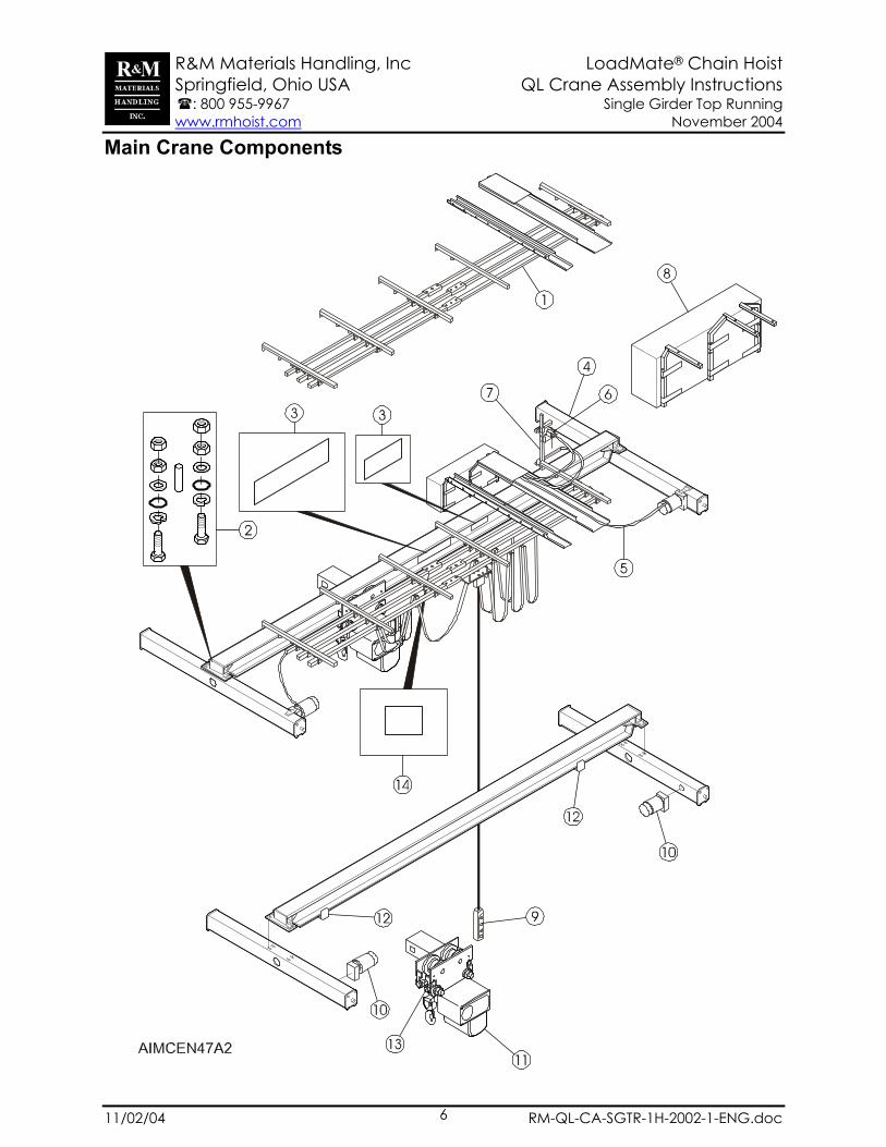
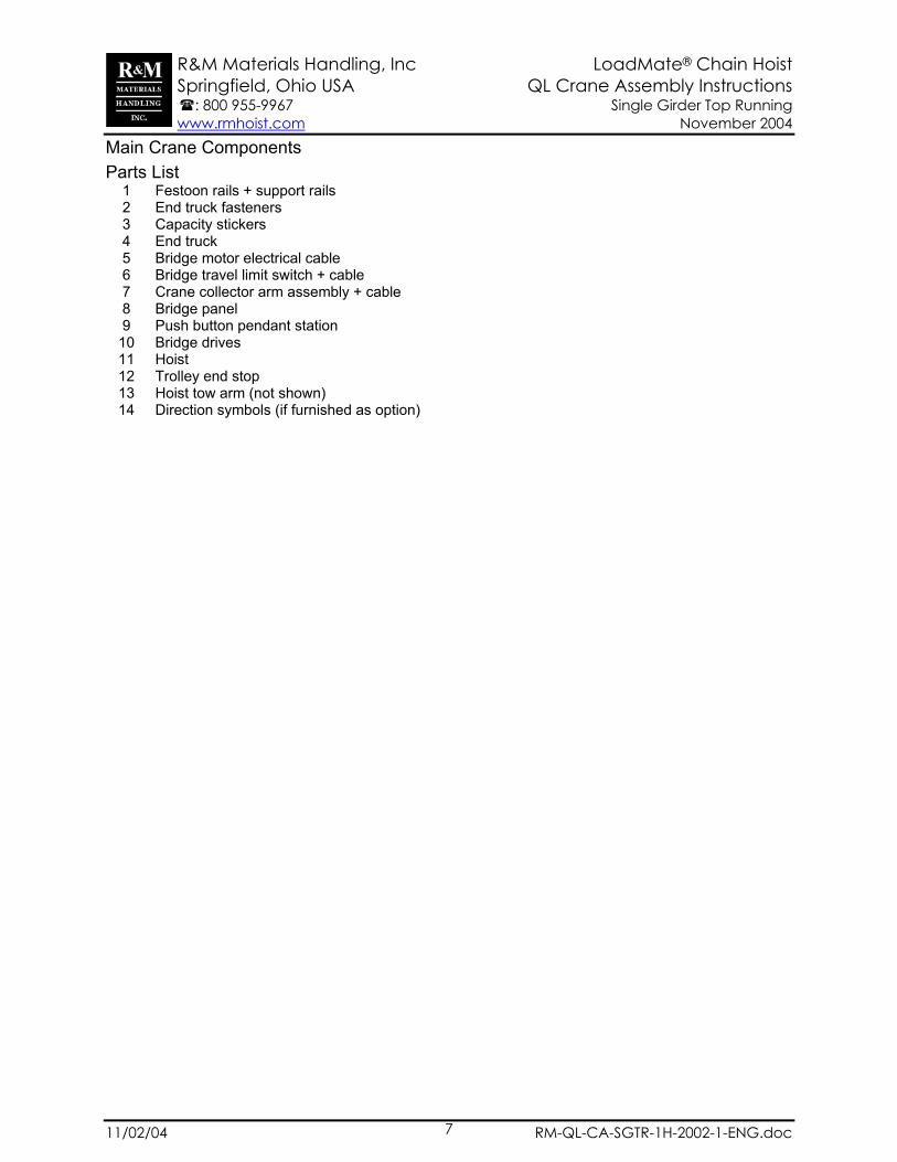
Main Crane Components
R&M Materials Handling, Inc LoadMate® Chain Hoist Springfield, Ohio USA QL Crane Assembly Instructions : 800 955-9967 Single Girder Top Running www.rmhoist.com November 2004
11/02/04 RM-QL-CA-SGTR-1H-2002-1-ENG.doc 7
Main Crane Components Parts List
1 Festoon rails + support rails 2 End truck fasteners 3 Capacity stickers 4 End truck 5 Bridge motor electrical cable 6 Bridge travel limit switch + cable 7 Crane collector arm assembly + cable 8 Bridge panel 9 Push button pendant station
10 Bridge drives 11 Hoist 12 Trolley end stop 13 Hoist tow arm (not shown) 14 Direction symbols (if furnished as option)

R&M Materials Handling, Inc LoadMate® Chain Hoist Springfield, Ohio USA QL Crane Assembly Instructions : 800 955-9967 Single Girder Top Running www.rmhoist.com November 2004
11/02/04 RM-QL-CA-SGTR-1H-2002-1-ENG.doc 8
Layout of Festoon Rails (Old Style)
Dimension chart
Bridge Panel W in [mm]
Layout H in [mm]
J in [mm]
K MAX in [mm]
L in [mm]
24 [600] 1 34.62 [880] 17 [432] 60 [1524] 9 [229] 36 [900] 2 46.50 [1181] 17 [432] 60 [1524] 9 [229] 47 [1200] 2 58.25 [1480] 17 [432] 60 [1524] 9 [229]
Layout 1 – Bridge Panel Width W < 24” [600mm]
Layout 2 – Bridge Panel Width W > 24” [600mm]
Note: Location of the bridge panel may be mirrored so the bridge panel is located at the opposite end of the crane. Runway conductors are located on the bridge panel end of crane.

R&M Materials Handling, Inc LoadMate® Chain Hoist Springfield, Ohio USA QL Crane Assembly Instructions : 800 955-9967 Single Girder Top Running www.rmhoist.com November 2004
11/02/04 RM-QL-CA-SGTR-1H-2002-1-ENG.doc 9
Dimension B = Beam flange width Hoist Type
A in [mm]
A1 in [mm]
C in [mm]
D in [mm]
E in [mm]
F in [mm]
G in [mm]
LM05 14 [355] 6 7/16 [163] 18 [457] 12 [406] 6-8 [150-200] 2 [50] 4 1/8 [105]LM10 14 [355] 6 7/16 [163] 18 [457] 12 [406] 6-8 [150-200] 2 [50] 4 1/8 [105]LM16 14 [355] 6 13/16 [173] 18 [457] 12 [406] 6-8 [150-200] 2 [50] 4 3/8 [112]LM20 14 [355] 6 13/16 [173] 18 [457] 12 [406] 6-8 [150-200] 2 [50] 4 3/8 [112]LM25 14 [355] 6 13/16 [173] 18 [457] 12 [406] 6-8 [150-200] 2 [50] 4 3/8 [112]
Position of the rails parallel with bridge girder 1st Rail = Round cable for bridge drive (located opposite end of bridge panel) 2nd Rail = Hoist power and control flat cable 3rd Rail = Sliding pendant

R&M Materials Handling, Inc LoadMate® Chain Hoist Springfield, Ohio USA QL Crane Assembly Instructions : 800 955-9967 Single Girder Top Running www.rmhoist.com November 2004
11/02/04 RM-QL-CA-SGTR-1H-2002-1-ENG.doc 10
Layout of Festoon Rails (New Style)
Dimension chart Bridge Panel W
in [mm] Layout C
in [mm] H
in [mm] J
in [mm] K MAX in [mm]
L in [mm]
24 [600] 1 16” [406] 15 3/4” [400] 17 [432] 60 [1524] 9 [229] 36 [900] 2 16” [406] 15 3/4” [400] 17 [432] 60 [1524] 9 [229]
47 [1200] 2 16” [406] 15 3/4” [400] 17 [432] 60 [1524] 9 [229]
Layout 1 – Bridge Panel Width, W < 24” [600mm]
Layout 2 – Bridge Panel Width, W > 24” [600mm]
Note: Location of the bridge panel may be mirrored so the bridge panel is located at the opposite end of the crane. Runway conductors are located on the bridge panel end of crane.

R&M Materials Handling, Inc LoadMate® Chain Hoist Springfield, Ohio USA QL Crane Assembly Instructions : 800 955-9967 Single Girder Top Running www.rmhoist.com November 2004
11/02/04 RM-QL-CA-SGTR-1H-2002-1-ENG.doc 11
Dimension B = Beam flange width
Hoist Type
A in [mm]
A1 in [mm]
C in [mm]
C1 in [mm]
D in [mm]
E in [mm]
F in [mm]
G in [mm]
LM05 14 [355] 6 7/16 [163] 16 [406] 3 1/8 [80] 12 [406] 6-8 [150-200] 2 [50] 4 1/8 [105]LM10 14 [355] 6 7/16 [163] 16 [406] 3 1/8 [80] 12 [406] 6-8 [150-200] 2 [50] 4 1/8 [105]LM16 14 [355] 6 13/16 [173] 16 [406] 3 1/8 [80] 12 [406] 6-8 [150-200] 2 [50] 4 3/8 [112]LM20 14 [355] 6 13/16 [173] 16 [406] 3 1/8 [80] 12 [406] 6-8 [150-200] 2 [50] 4 3/8 [112]LM25 14 [355] 6 13/16 [173] 16 [406] 3 1/8 [80] 12 [406] 6-8 [150-200] 2 [50] 4 3/8 [112]
Position of the rails parallel with bridge girder 1st Rail = Round cable for bridge drive (located opposite end of bridge panel) 2nd Rail = Hoist power and control flat cable 3rd Rail = Sliding pendant

R&M Materials Handling, Inc LoadMate® Chain Hoist Springfield, Ohio USA QL Crane Assembly Instructions : 800 955-9967 Single Girder Top Running www.rmhoist.com November 2004
11/02/04 RM-QL-CA-SGTR-1H-2002-1-ENG.doc 12
Hoist Tow Arm Assembly Connect the chain to the lead festoon trolley (2nd rail) and to the hoist tow arm. Fasten tow arm to trolley as shown.
Bridge Drive Assembly
1. 2. 3. 4.
GES3
Parts List
1 End truck 2 Washer 4 per drive DIN125-A8-A3G (GES3 or GES4) DIN125-A12-A3G
3 Socket head cap screw 4 per drive DIN912-M8x85-8.8-A3G (GES3) DIN912-M8x100-8.8-A3G (GES4) DIN912-M12x140-8.8-A3G
4 Bridge drive GES3 or GES4 drive type GES5 drive type
Explanations for NOTES in the drawing Clean the spline and mounting flanges of dirt and of the rust protection wax. Grease the spline lightly before assembly. Use a rubber-head hammer to help slide the drive into place. Do not use a metal hammer. Recommended tightening torque: M8 SHCS 15 ft-lb (20 Nm); M12 SHCS 55ft-lb (77Nm) Remove the protection pin from the breather plug on drives that mount vertical only.

R&M Materials Handling, Inc LoadMate® Chain Hoist Springfield, Ohio USA QL Crane Assembly Instructions : 800 955-9967 Single Girder Top Running www.rmhoist.com November 2004
11/02/04 RM-QL-CA-SGTR-1H-2002-1-ENG.doc 13
Trolley End Stop Assembly
2
5
5 66
7
1
3
4
AIMCEN60A Before installing trolley mounted hoists, the end stops must be installed for all trolleys mounted on open-end beams. The end stops must be properly mounted so that the bumpers absorb any impact forces. Do not allow the trolley wheels to impact rail stops. In addition, the end stops must be positioned on the beam so that the hoist unit does not impact the crane structure, end trucks and/or bridge drives. Parts List
1 End stop 2 Bolt 3 Nut 4 Washer 5 Washer 6 Nut 7 Threaded rod
Explanation for NOTES in the drawing Mount and position the trolley end stop on the bridge girder. Turn nuts (item 6) on each end of threaded rod until snug making sure the end stops are squared on the beam flange. Tighten top bolts (item 2) on each end stop. Tighten nuts (item 6) on each end of threaded rod. Lock top bolt by tightening nut (item 3) against end stop. Make sure that the trolley bumper contacts the center of end stop!
R&M Materials Handling, Inc LoadMate® Chain Hoist Springfield, Ohio USA QL Crane Assembly Instructions : 800 955-9967 Single Girder Top Running www.rmhoist.com November 2004
11/02/04 RM-QL-CA-SGTR-1H-2002-1-ENG.doc 14
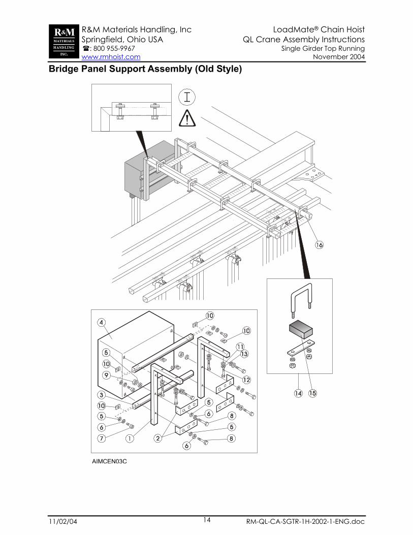
Bridge Panel Support Assembly (Old Style)
AIMCEN03C

R&M Materials Handling, Inc LoadMate® Chain Hoist Springfield, Ohio USA QL Crane Assembly Instructions : 800 955-9967 Single Girder Top Running www.rmhoist.com November 2004
11/02/04 RM-QL-CA-SGTR-1H-2002-1-ENG.doc 15
Bridge Panel Support Assembly (Old Style) Parts List
1 Support bracket 2 Plate 3 C-rail 4 Bridge panel 5 Washer 6 Spring washer 7 Bolt 8 Bolt 9 Nut
10 Square nut (for C-rail) 11 Washer 12 Bolt 13 Spring washer 14 Clamp 15 Rubber spacer 16 Ladder frame & C-rail
Explanation for NOTES in the drawing Mount the support brackets to bridge panel before mounting bridge panel to crane. Slide bridge panel assembly onto the C-rails of the ladder frame assembly.
The ladder frame assembly for the bridge panel does not support any festoon C-rails that run parallel with the bridge girder.

R&M Materials Handling, Inc LoadMate® Chain Hoist Springfield, Ohio USA QL Crane Assembly Instructions : 800 955-9967 Single Girder Top Running www.rmhoist.com November 2004
11/02/04 RM-QL-CA-SGTR-1H-2002-1-ENG.doc 16
Bridge Panel Support Assembly (New Style)

R&M Materials Handling, Inc LoadMate® Chain Hoist Springfield, Ohio USA QL Crane Assembly Instructions : 800 955-9967 Single Girder Top Running www.rmhoist.com November 2004
11/02/04 RM-QL-CA-SGTR-1H-2002-1-ENG.doc 17
Bridge Panel Support Assembly (New Style)
1918
Bracket Location Dimensions
BC
HC
W W
BC BC1
HCHC
W
HC1
BC BC1
Bridge Panel, W
in [mm] BC
in [mm] BC1
in [mm] HC
in [mm] HC1
in [mm] 23 5/8” [600] 7 7/8” [200] --- 19 11/16” [500] --- 35 7/16” [900] 3 15/16” [100] 19 11/16” [500] 15 3/4” [400] 15 3/4” [400] 47 1/8” [1200] 7 7/8” [200] 27 9/16” [700] 19 11/16” [500] ----
Parts List
1 Enclosure support bracket – left hand 150 mm 15 Screw DIN933-M8x20-8.8-A3G 2 Cable holding bracket 16 Flat washer M8 DIN125-A8-A3G 3 Bridge panel enclosure 17 Auxiliary support plate 4 Flat washer M8 DIN125-A8-A3G 18 Rail clamp + fastener hardware 5 Locking nut M8 DIN985-M8-8-A3G 19 Beam clip + fastener hardware 6 Threaded stud DIN913-M8x40-A3G 7 Enclosure support bracket – right hand 150 mm 8 Screw DIN933-M8x45-8.8-A3G 9 Lock washer 10 Flat washer M8 DIN125-A8-A3G 11 Square nut 12 Enclosure support bracket – 50 mm 13 Support plate and cable tray 14 Cover
Explanation for NOTES in the drawing Mount the brackets to bridge panel before mounting bridge panel to the support plate. The festoon rails are clamped to the support plate and cable tray and to the auxiliary support plate for the bridge panel. Use rail clamps.
View of the rail clamps on the support plate & cable tray for the bridge panel
View of the beam clip for the support plate & cable tray for the bridge panel

R&M Materials Handling, Inc LoadMate® Chain Hoist Springfield, Ohio USA QL Crane Assembly Instructions : 800 955-9967 Single Girder Top Running www.rmhoist.com November 2004
11/02/04 RM-QL-CA-SGTR-1H-2002-1-ENG.doc 18
Festoon Assembly

R&M Materials Handling, Inc LoadMate® Chain Hoist Springfield, Ohio USA QL Crane Assembly Instructions : 800 955-9967 Single Girder Top Running www.rmhoist.com November 2004
11/02/04 RM-QL-CA-SGTR-1H-2002-1-ENG.doc 19
Festoon Assembly Parts list
1 Pendant trolley 2 Support arm 3 C-rail 4 Track coupler + fastener hardware (4 bolts per coupler) 5 Rail clamp + fastener hardware 6 Beam clip + fastener hardware 7 Pendant trolley detail 8 Cable for drive motor 2 9 Cable trolley
10 End stop + fastener hardware 11 End clamp (stationary) + fastener hardware 12 Clip for cable attachment if furnished as option 13 Tow trolley for hoist power and control festoon cables
Explanation for NOTES in the drawing Make sure that the C-rails are positioned into the track coupler so the rail joint is visible at the center holes of the coupler. After properly positioning the C-rail into the track coupler, tighten each bolt on coupler. Lock each coupler bolt by tightening the nut against the coupler. Make sure that the C-rail joint is smooth for tow trolley travel Fasten each C-rail to each support arm by using the bracket. Tighten the bolts. Tighten the strain relief wires on both sides of the plug so that pendant cable is making a loop as shown. Tighten each wire clamp.
R&M Materials Handling, Inc LoadMate® Chain Hoist Springfield, Ohio USA QL Crane Assembly Instructions : 800 955-9967 Single Girder Top Running www.rmhoist.com November 2004
11/02/04 RM-QL-CA-SGTR-1H-2002-1-ENG.doc 20
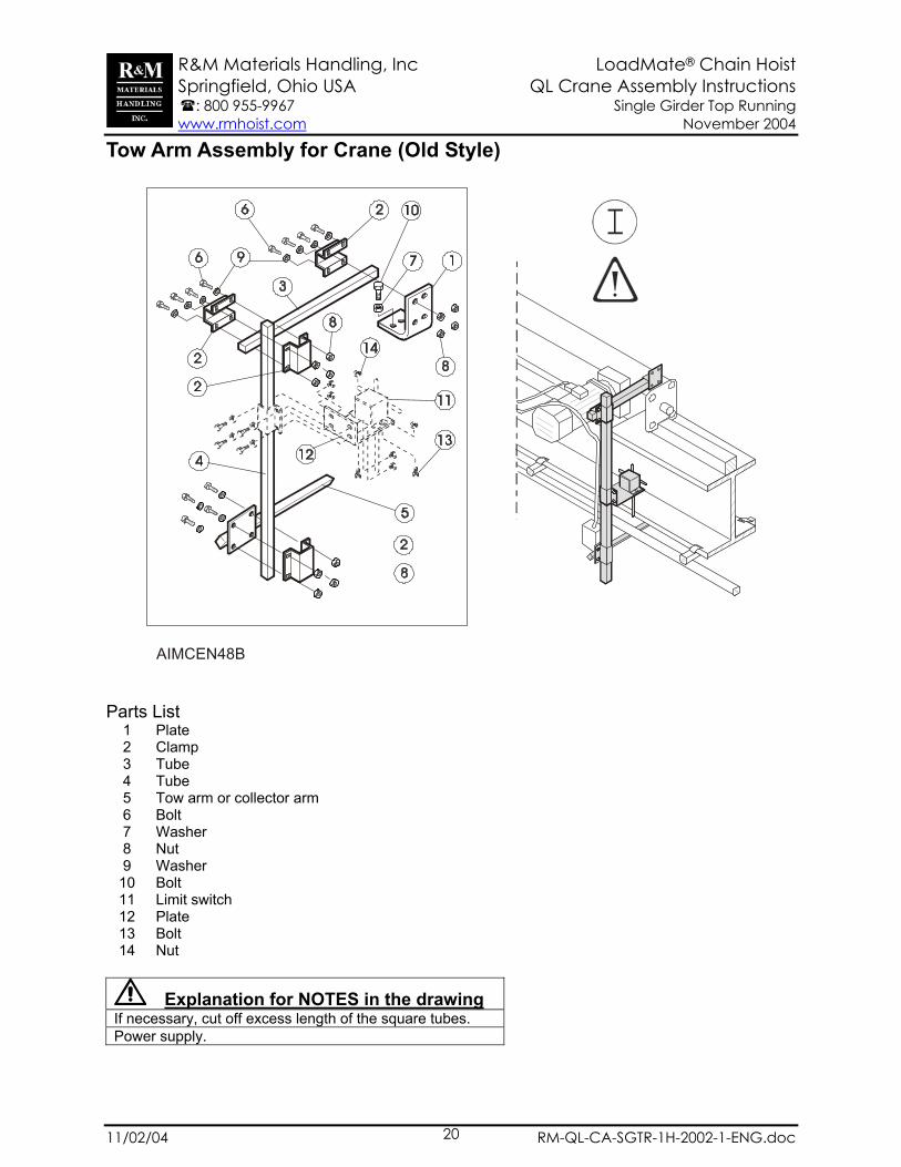
Tow Arm Assembly for Crane (Old Style)
AIMCEN48B Parts List
1 Plate 2 Clamp 3 Tube 4 Tube 5 Tow arm or collector arm 6 Bolt 7 Washer 8 Nut 9 Washer
10 Bolt 11 Limit switch 12 Plate 13 Bolt 14 Nut
Explanation for NOTES in the drawing If necessary, cut off excess length of the square tubes. Power supply.

R&M Materials Handling, Inc LoadMate® Chain Hoist Springfield, Ohio USA QL Crane Assembly Instructions : 800 955-9967 Single Girder Top Running www.rmhoist.com November 2004
11/02/04 RM-QL-CA-SGTR-1H-2002-1-ENG.doc 21
Tow Arm Assembly for Crane (New Style)
The mounting bracket (item 5) is to allow the location of the tow arm to be adjusted as needed.
Parts List 1 Horizontal tow arm 2 Vertical tube 3 Clamping plate 4 Mounting plate (optional with item 5) 5 Mounting bracket 6 M10 x 20 screw (DIN933-M10x20-8.8-A3G) 7 M10 x 35 screw (DIN933-M10x35-8.8-A3G) 8 M8 x 80 screw (DIN931-M8x80-8.8-A3G) 9 M8 x 140 screw (DIN931-M8x140-8.8-A3G)
10 Flat washer M10 11 Flat washer M8 12 M10 locking nut (DIN985-M10-8-A3G) 13 M8 locking nut (DIN985-M8-8-A3G) 14 Collector arm
Explanation for NOTES in the drawing If necessary, cut off excess length of the square tubes.

R&M Materials Handling, Inc LoadMate® Chain Hoist Springfield, Ohio USA QL Crane Assembly Instructions : 800 955-9967 Single Girder Top Running www.rmhoist.com November 2004
11/02/04 RM-QL-CA-SGTR-1H-2002-1-ENG.doc 22
Bridge Travel Limit Switch The limit switch for bridge travel is supplied as standard in the QL Modular Crane Packages. Unless otherwise specified at order inquiry, this limit switch will operate as a slow-down limit. The function of a slow-down limit is to deactivate bridge fast speed and to changeover to slow speed when the bridge-travel limit switch is tripped as the crane approaches either end of the runway. Bridge fast speed is deactivated until the limit switch is reset back to its neutral position. Reversing the direction of the crane so that the limit switch turnstile strikes again the trip device resets the limit switch. Once the switch is reset back to its neutral position, bridge fast speed becomes available again. The limit switch is a maintained type and it is equipped with a turnstile. The trip device must be located on the runway beam positioned to trip the turnstile. The user is responsible for furnishing and mounting the trip device of which is made from either rod or bar stock. The bridge panel is Ready-to-Run after the user connects all the applicable plugs including the limit switch. Not Installing Bridge Travel Limit Switch R&M strongly recommends installing the supplied limit switch for bridge travel as a precaution against damaging impact. If the user decides not to install the bridge limit switch, then wire jumpers must be added to the bridge controls to accommodate for the missing limit switch connection. Adding these jumpers bypasses the limit switch circuit and brings online bridge fast speed that otherwise is disabled because the switch was not installed. Refer to the wiring diagrams, in particular, the wiring diagram for the bridge panel that are included with your manuals before making any jumper connections. Install a jumper from terminal X1: 50 to limit switch input(s) on the inverter in the bridge panel. Depending on the inverter type, there could be more than one limit switch input on the inverter. Each one of these limit switch connections on the inverter must be jumper connected. For example, if multiple switch inputs on the inverter are being used, then add a jumper from terminal X1: 50 to Input “A”, then from Input “A” to Input “ B” and so on.
R&M Materials Handling, Inc LoadMate® Chain Hoist Springfield, Ohio USA QL Crane Assembly Instructions : 800 955-9967 Single Girder Top Running www.rmhoist.com November 2004
11/02/04 RM-QL-CA-SGTR-1H-2002-1-ENG.doc 23
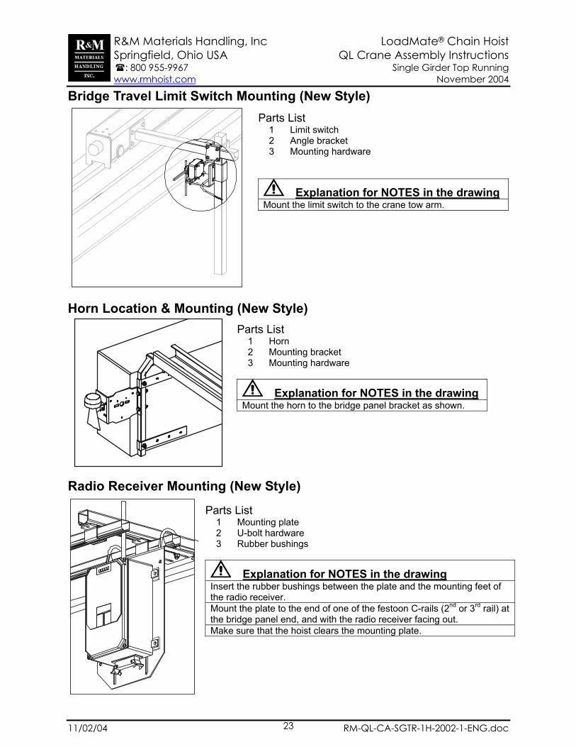
Bridge Travel Limit Switch Mounting (New Style)
Horn Location & Mounting (New Style)
Radio Receiver Mounting (New Style)
Parts List 1 Limit switch 2 Angle bracket 3 Mounting hardware
Explanation for NOTES in the drawing Mount the limit switch to the crane tow arm.
Parts List 1 Mounting plate 2 U-bolt hardware 3 Rubber bushings
Explanation for NOTES in the drawing Insert the rubber bushings between the plate and the mounting feet of the radio receiver. Mount the plate to the end of one of the festoon C-rails (2nd or 3rd rail) at the bridge panel end, and with the radio receiver facing out. Make sure that the hoist clears the mounting plate.
Parts List 1 Horn 2 Mounting bracket 3 Mounting hardware
Explanation for NOTES in the drawing Mount the horn to the bridge panel bracket as shown.
R&M Materials Handling, Inc LoadMate® Chain Hoist Springfield, Ohio USA QL Crane Assembly Instructions : 800 955-9967 Single Girder Top Running www.rmhoist.com November 2004
11/02/04 RM-QL-CA-SGTR-1H-2002-1-ENG.doc 24
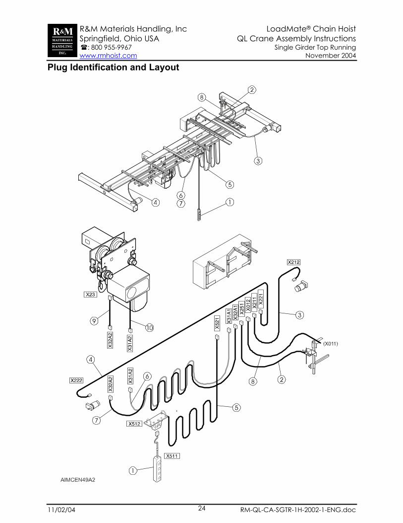
Plug Identification and Layout

R&M Materials Handling, Inc LoadMate® Chain Hoist Springfield, Ohio USA QL Crane Assembly Instructions : 800 955-9967 Single Girder Top Running www.rmhoist.com November 2004
11/02/04 RM-QL-CA-SGTR-1H-2002-1-ENG.doc 25
Plug Identification and Layout Parts Lists
1 Pendant 2 Cable for bridge travel limit switch 3 Cable for bridge motor 4 Cable for bridge motor 2 5 Cable for pendant trolley 6 Cable for hoist power 7 Cable for hoist control 8 Cable for crane main power supply 9 Plug adapter for hoist control
10 Plug adapter for hoist power. Hardwired to hoist.
R&M Materials Handling, Inc LoadMate® Chain Hoist Springfield, Ohio USA QL Crane Assembly Instructions : 800 955-9967 Single Girder Top Running www.rmhoist.com November 2004
11/02/04 RM-QL-CA-SGTR-1H-2002-1-ENG.doc 26
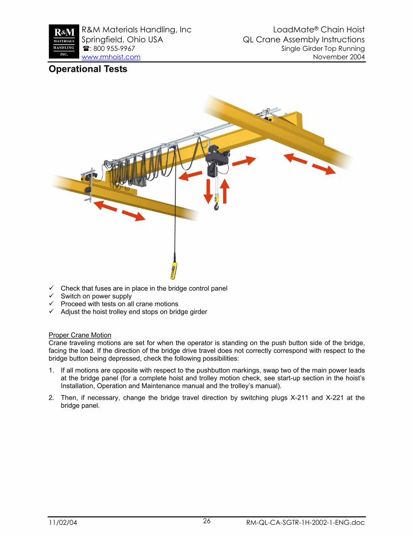
Operational Tests
Check that fuses are in place in the bridge control panel Switch on power supply Proceed with tests on all crane motions Adjust the hoist trolley end stops on bridge girder
Proper Crane Motion Crane traveling motions are set for when the operator is standing on the push button side of the bridge, facing the load. If the direction of the bridge drive travel does not correctly correspond with respect to the bridge button being depressed, check the following possibilities:
1. If all motions are opposite with respect to the pushbutton markings, swap two of the main power leads at the bridge panel (for a complete hoist and trolley motion check, see start-up section in the hoist’s Installation, Operation and Maintenance manual and the trolley’s manual).
2. Then, if necessary, change the bridge travel direction by switching plugs X-211 and X-221 at the bridge panel.