Embed Size (px)
Citation preview

Qi power control principles and consequences on PTx design
Christian Beia, Guillaume Combes, Lionel Cimaz
STMicroelectronics
November 16th, 2017
Receiver (PRx)Transmitter (PTx)
load
reg
Vrect
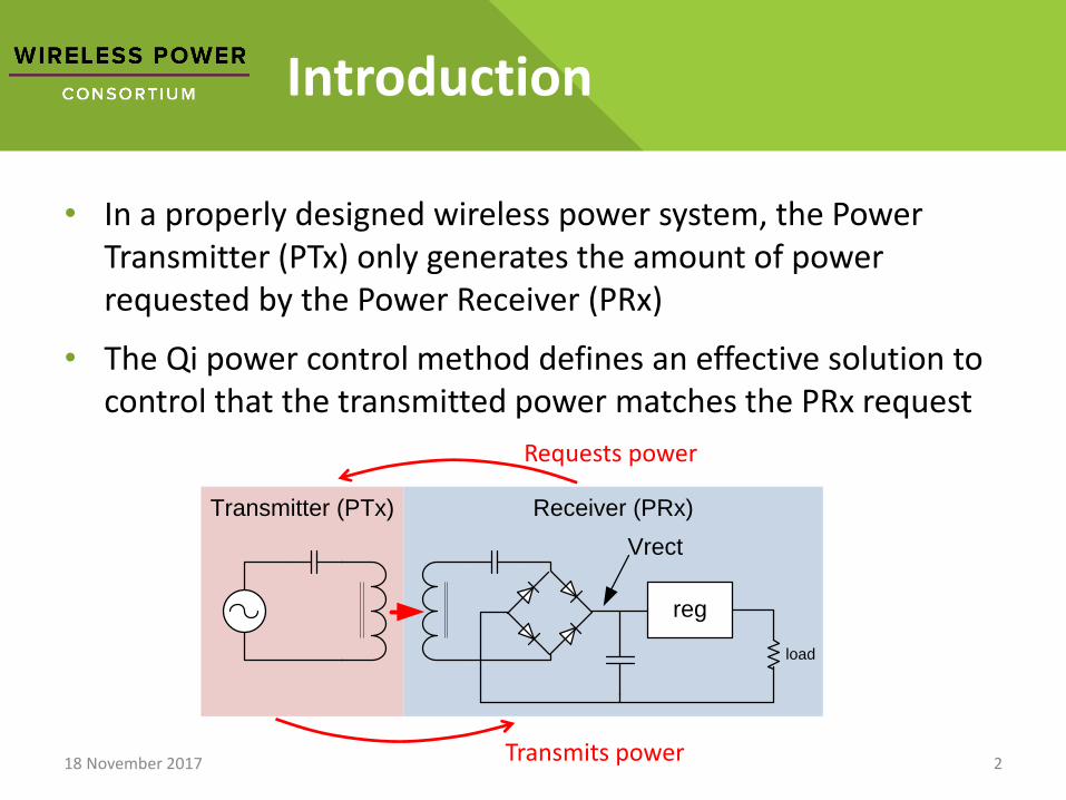
Introduction
• In a properly designed wireless power system, the Power Transmitter (PTx) only generates the amount of power requested by the Power Receiver (PRx)
• The Qi power control method defines an effective solution to control that the transmitted power matches the PRx request
18 November 2017 2Transmits power
Requests power

Receiver (PRx)Transmitter (PTx)
load
reg
Vrect
Optimizing Power Efficiency with Qi
• To transmit power, the PTx generates a magnetic field which is captured by the PRx
• The PRx rectified voltage (Vrect) depends on the strength of this magnetic field (Faraday’s law)
➢ The stronger is the magnetic field, the larger is the circulating current in the PTx, the more power is lost by joule effect
➢ The Qi system optimizes power efficiency by using a PTx field which is just enough to get PRx Vrect voltage at a desired value
18 November 2017 3
Cs
load
reg
regulation error = Vrect - Vtarget
Message
adjust PTx energy
effect on Vrect
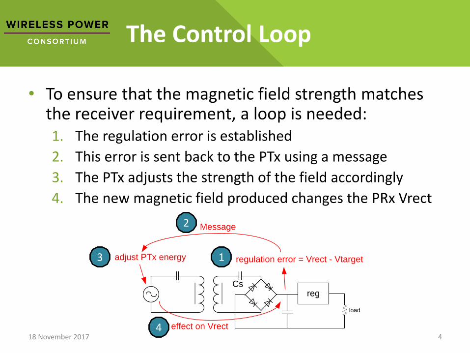
The Control Loop
• To ensure that the magnetic field strength matches the receiver requirement, a loop is needed:1. The regulation error is established
2. This error is sent back to the PTx using a message
3. The PTx adjusts the strength of the field accordingly
4. The new magnetic field produced changes the PRx Vrect
18 November 2017 4
1
2
3
4
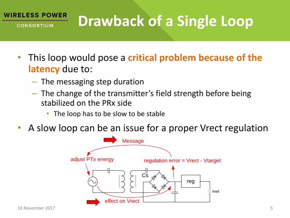
Drawback of a Single Loop
• This loop would pose a critical problem because of the latency due to:– The messaging step duration
– The change of the transmitter’s field strength before being stabilized on the PRx side• The loop has to be slow to be stable
• A slow loop can be an issue for a proper Vrect regulation
18 November 2017 5
Cs
load
reg
regulation error = Vrect - Vtarget
Message
adjust PTx energy
effect on Vrect
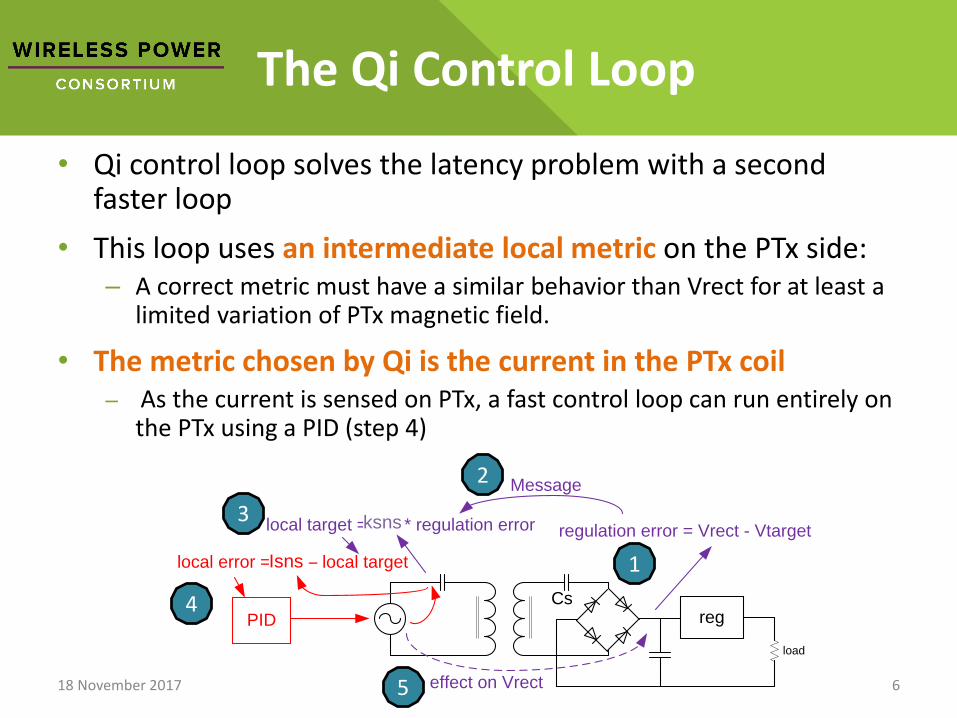
The Qi Control Loop
• Qi control loop solves the latency problem with a second faster loop
• This loop uses an intermediate local metric on the PTx side:– A correct metric must have a similar behavior than Vrect for at least a
limited variation of PTx magnetic field.
• The metric chosen by Qi is the current in the PTx coil– As the current is sensed on PTx, a fast control loop can run entirely on
the PTx using a PID (step 4)
18 November 2017 6
Cs
load
reg
regulation error = Vrect - Vtarget
Message
effect on Vrect
local error = sns – local target
local target = sns * regulation error
PID
1
2
3
4
5
Isns
ksns
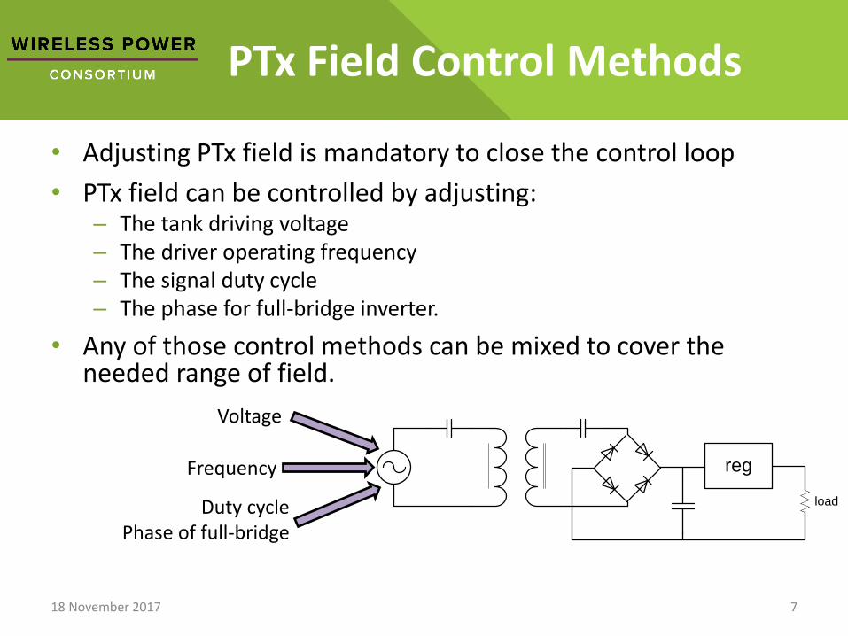
PTx Field Control Methods
• Adjusting PTx field is mandatory to close the control loop
• PTx field can be controlled by adjusting:– The tank driving voltage– The driver operating frequency– The signal duty cycle– The phase for full-bridge inverter.
• Any of those control methods can be mixed to cover the needed range of field.
18 November 2017 7
load
regFrequency
Voltage
Duty cyclePhase of full-bridge
Messaging and Control Loop
• Messaging is the only way to transmit the actual regulation error information from PRx to PTx.
• By consequence, the messaging function is critical.
If no message:
➢No regulation error information
➢No regulation loop
18 November 2017 8
Qi Messaging
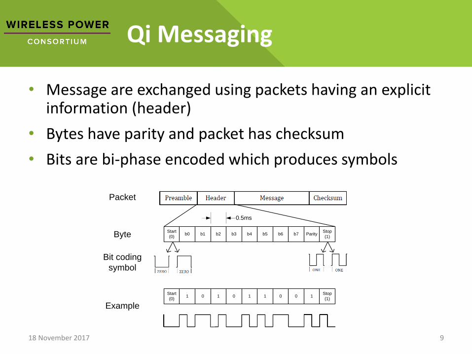
• Message are exchanged using packets having an explicit information (header)
• Bytes have parity and packet has checksum
• Bits are bi-phase encoded which produces symbols
18 November 2017 9
Start
(0)b0 b1 b2 b3 b4 b5 b6 b7 Parity
Stop
(1)
Start
(0)1 0 1 0 1 1 0 0 1
Stop
(1)
Packet
Byte
Bit coding
symbol
Example
0.5ms
PRx Symbol Transmission
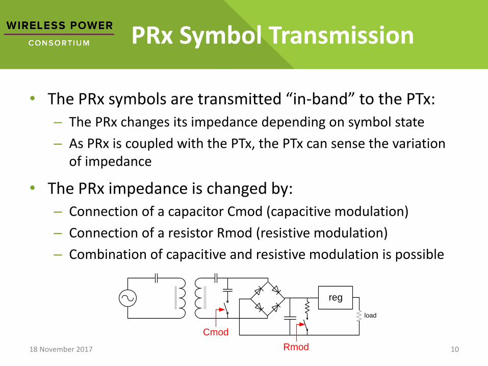
• The PRx symbols are transmitted “in-band” to the PTx:
– The PRx changes its impedance depending on symbol state
– As PRx is coupled with the PTx, the PTx can sense the variation of impedance
• The PRx impedance is changed by:
– Connection of a capacitor Cmod (capacitive modulation)
– Connection of a resistor Rmod (resistive modulation)
– Combination of capacitive and resistive modulation is possible
18 November 2017 10
load
reg
Cmod
Rmod
Symbol PTx Reception
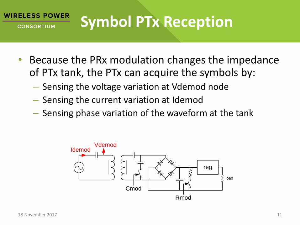
• Because the PRx modulation changes the impedance of PTx tank, the PTx can acquire the symbols by:– Sensing the voltage variation at Vdemod node
– Sensing the current variation at Idemod
– Sensing phase variation of the waveform at the tank
18 November 2017 11
load
reg
Cmod
Rmod
IdemodVdemod
Missing Modulation
• The overall tank is a very complex impedance, impacted by:– The PRx load variation
– PRx and PTx topology
– Coupling factor between PTx and PRx
• Because of this, in some cases PRx modulation may not produce, at PTx side, any variation of Vdemod , Idemod or phase
• While it is possible to miss one of demodulation signals, missing voltage, current and phase at the same time is very unlikely.
18 November 2017 12
Example of Missing Vdemod
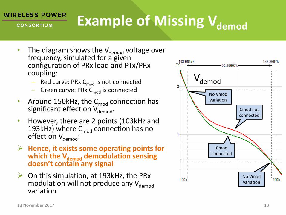
• The diagram shows the Vdemod voltage over frequency, simulated for a given configuration of PRx load and PTx/PRxcoupling:– Red curve: PRx Cmod is not connected– Green curve: PRx Cmod is connected
• Around 150kHz, the Cmod connection has significant effect on Vdemod.
• However, there are 2 points (103kHz and 193kHz) where Cmod connection has no effect on Vdemod:
➢ Hence, it exists some operating points for which the Vdemod demodulation sensing doesn’t contain any signal
➢ On this simulation, at 193kHz, the PRxmodulation will not produce any Vdemodvariation
18 November 2017 13
Vdemod
Cmod not connected
Cmod connected
No Vmodvariation
No Vmodvariation
Example of Phase and Vdemod
Missing Modulation
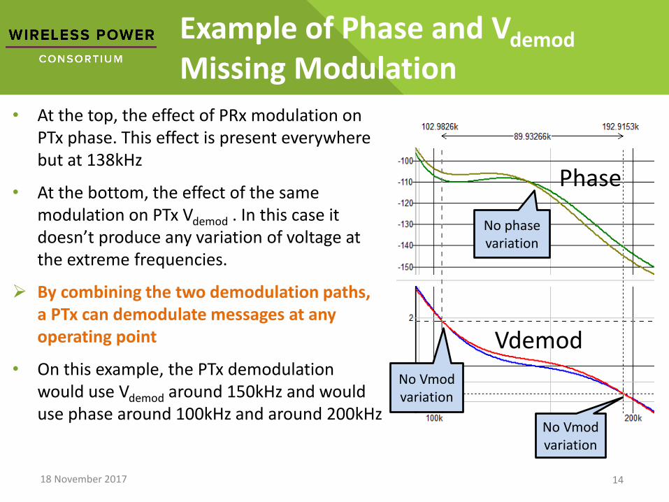
• At the top, the effect of PRx modulation on PTx phase. This effect is present everywhere but at 138kHz
• At the bottom, the effect of the same modulation on PTx Vdemod . In this case it doesn’t produce any variation of voltage at the extreme frequencies.
➢ By combining the two demodulation paths, a PTx can demodulate messages at any operating point
• On this example, the PTx demodulation would use Vdemod around 150kHz and would use phase around 100kHz and around 200kHz
18 November 2017 14
Vdemod
Phase
No Vmodvariation
No phase variation
No Vmodvariation
Message Degradation
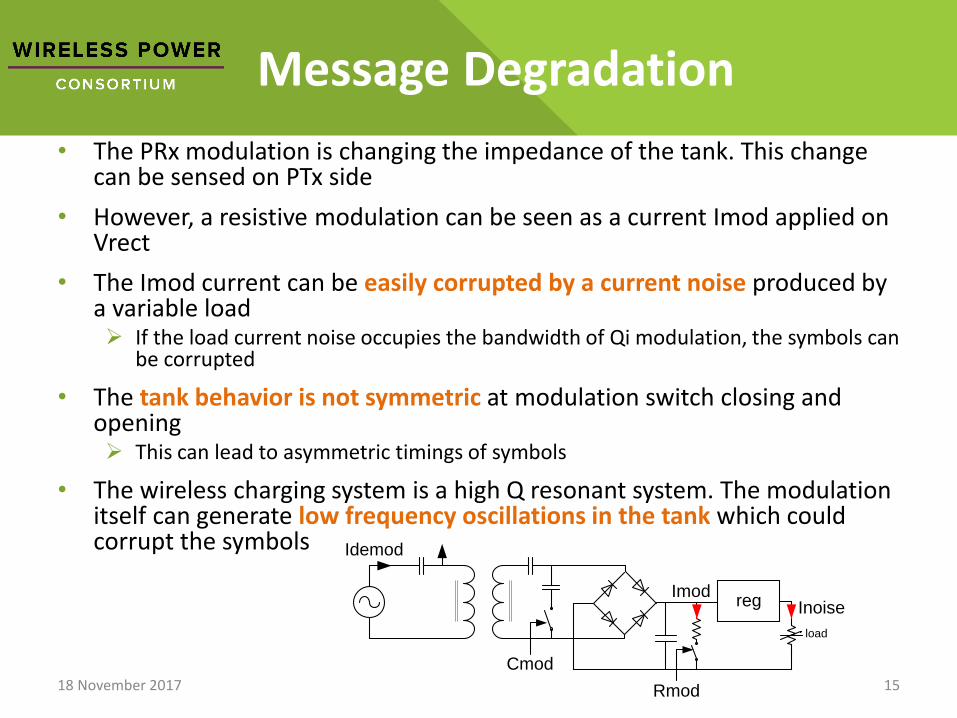
• The PRx modulation is changing the impedance of the tank. This change can be sensed on PTx side
• However, a resistive modulation can be seen as a current Imod applied on Vrect
• The Imod current can be easily corrupted by a current noise produced by a variable load➢ If the load current noise occupies the bandwidth of Qi modulation, the symbols can
be corrupted
• The tank behavior is not symmetric at modulation switch closing and opening➢ This can lead to asymmetric timings of symbols
• The wireless charging system is a high Q resonant system. The modulation itself can generate low frequency oscillations in the tank which could corrupt the symbols
18 November 2017 15
load
reg
Cmod
Rmod
Idemod
ImodInoise
Demodulation Challenges Summary
• The PTx capability of message demodulation is critical
– To close the regulation loop
– To capture some Qi messages which are not repeated
• Identification & configuration packets at PRx attachment
• End of power transfer messages
• …
• The demodulation can become difficult
– Depending on the operating point, some demodulation nodes can have no useful signal
– Depending on PRx design and loading, some demodulation node signals can be degraded
18 November 2017 16

Multiple Paths Demodulation Solution
• To improve the demodulation quality, multi-path solution can be implemented.
• The diagram below shows a parallel demodulation on phase (green), voltage (blue) and current (red). The first valid decoded message (parity and CRC OK) is propagated
• It allows to systematically find a path with effective modulation– The paths chosen have some orthogonality with regard to the miss of modulation
signal
• It allows to support better a signal degradation:– A given signal degradation has different effect on PTx sense points. Multiplying the
sense points offers better chance to decode the original message– The parallel demodulation allows getting messages even if one path is corrupted in
middle of transmission
18 November 2017 17
Vdemoddig
filter
dig
filter
Bi-phase
decoding
Bi-phase
decoding
Message
decode
Message
decodeSelect correct
messageIdemod
jdig
filter
Bi-phase
decoding
Message
decode
Conclusion
• Qi system allows inductive power transfer with optimum efficiency thanks to its smart control loop
• Qi in-band messaging is critical for the control loop operation
• The message reception can be challenging
• Multi-path demodulation improves the reception quality
18 November 2017 18

18 November 2017 19Confidential