Embed Size (px)
Citation preview

S U R E S H A D E ® T E C H N I C A L D O C U M E N T A T I O N
PTXTM Power T-Top ShadeINSTALLATION INSTRUCTIONS AND OWNER'S MANUAL
PLACEHOLDER
IMAGE

2 sureshade.com Rev: 06.02.21877-333-8323 CCD-0004328
TABLE OF CONTENTS
Contents
GENERAL INFORMATION ................................................................................................................................................. 3Introduction ............................................................................................................................................................ 3Contact Information ............................................................................................................................................ 3Customer Support ............................................................................................................................................... 3SureShade Limited Product Warranty Statement .................................................................................... 3
SAFETY .................................................................................................................................................................................... 5Safety Descriptions .............................................................................................................................................. 5Important safety messages ............................................................................................................................... 5Important Instructions ........................................................................................................................................ 6Safety Warnings .................................................................................................................................................... 6
PREPARATION....................................................................................................................................................................... 7Tools Required ....................................................................................................................................................... 7Skill Level of Installer ........................................................................................................................................... 7Installation Time Frame ...................................................................................................................................... 7
INSTALLATION ..................................................................................................................................................................... 8General System Components ........................................................................................................................... 8System Measurement and Component Preparation ............................................................................... 8Hardtop Actuator Mounting ............................................................................................................................ 9T-Top Actuator Mounting .................................................................................................................................13Securing the Crossbars and Installing Canvas ..........................................................................................16Electrical Connections .....................................................................................................................................18Wiring Diagram....................................................................................................................................................19
MAINTENANCE ..................................................................................................................................................................19Regular Cleaning .................................................................................................................................................19Canvas .....................................................................................................................................................................19Long-Term Storage .............................................................................................................................................19
TROUBLESHOOTING .......................................................................................................................................................20Troubleshooting Chart ......................................................................................................................................20

3 Rev: 06.02.21 sureshade.com877-333-8323 CCD-0004328
GENERAL INFORMATION
INTRODUCTIONThank you for purchasing a SureShade® retractable shade for your boat.Invented by boaters for boaters, SureShade is the new standard for shade on boats. Our automated or manual retractable shade systems are featured on over 50 boat brands as factory or aftermarket installations.
SureShade is the only U.S.-made telescoping marine sunshade on the market, with patents in the U.S., Canada, Europe and China. SureShade is committed to improving sun safety on boats with shade systems that give boaters more sun protection... where and when they need it.
CONTACT INFORMATION
CUSTOMER SUPPORT We take pride in offering an unprecedented level of customer service to our boat builders, dealers and—most importantly—the boaters who use our sunshade systems.
Whether you purchased your sunshade system as a factory-install option, an aftermarket installation through your local boat dealer or directly from us, you can have confidence in continued customer service resources from SureShade.
Should you require assistance with your SureShade installation, our technical experts are available from 9am - 5pm EST Monday through Friday via email at [email protected], or call us at 877-333-8323.
Further customer resources and information can be found on our website at: https://www.sureshade.com/service/
SURESHADE LIMITED PRODUCT WARRANTY STATEMENT SureShade provides the following Limited Warranty of its electric and manual sunshade awning systems.
SureShade warrants that the shade framework—which consists of the actuator drive assemblies, crossbars, roller assembly, mounts and in the case of an electric shade, the motors, controller and wire that connects the actuators to the controller—will be free from material defects and workmanship and will repair or replace, at its sole discretion, any inoperable components that are reported within three years from the date of shade sale to original purchaser—boat builder, dealer or private boat owner.
SureShade will also replace, at its sole discretion, the canvas component of the shade system (electric or manual) when reported defective within one year from the date of canvas manufacture as indicated on the white manufacturer tag attached to the canvas (tag must remain attached for warranty purposes).
Exclusions to this limited warranty are as follows:• Damage resulting from abuse, misuse, neglect, improper installation, improper operation, improper maintenance,
attempted repair efforts resulting in further damage, power surges, underpowering or forcing operation in low voltage situations, improper stowage for ground transportation, inclement weather or other act of nature.
• Damage resulting from leaving the shade extended unattended during inclement weather.• Damage resulting from corrosion. • Any shade product that has been altered or modified from SureShade factory specifications. • Any shade that’s installed without SureShade-supplied or approved mounting components. • Removal and/or dismantling of the shade and its components (including actuator drive system) without proper notification
to SureShade.• Deterioration of the canvas thread and stitching.• Travel time to/from boat to troubleshoot, repair and/or replace components.• Damage resulting from leaving the shade extended unattended during inclement weather. • Labor cost and expenses associated with removal or reinstallation of other components in order to access the shade
product components. • Any cost associated with production downtime or time spent troubleshooting or reviewing troubleshooting
documentation/videos. • Excessive labor cost beyond recommended standard labor repair rates.

4 sureshade.com Rev: 06.02.21877-333-8323 CCD-0004328
SureShade reserves the right to utilize reconditioned, refurbished, repaired or remanufactured products or parts in the warranty repair or replacement process. Such products and parts will be comparable in function and performance to an original product or part and warranted for the remainder of the original warranty period.
In no event shall any repair or replacement under this Limited Warranty exceed the fair market value of the product as of the date of the owner's claim.
Acceptance of any product returned for any refund provided by SureShade shall not be deemed an admission that the product is defective.
In order for a warranty claim to be deemed valid, the following information must be provided to SureShade immediately after discovery of any defect:
• Description of the nature of the problem.• Details of the boat that the shade is installed on—year, make, model and hull identification number.• Date of shade purchase, or in the case of factory install, date of boat purchase. • Details of the installation—Factory install? Dealer install? Private install?
SureShade will make every effort to troubleshoot, determine root cause and fully resolve the issue, either directly or with an experienced marine technician. SureShade is solely responsible for determining and authorizing the remedial actions to be performed either by a SureShade technician or an experienced marine technician approved by SureShade.
The remedy of repair or replacement of parts or materials that are found to be defective in factory materials or workmanship covered by this Limited Warranty shall constitute the owner's sole and exclusive remedy against SureShade for any claims whatsoever or economic loss resulting from product failure.
Please contact us or call 877-333-8323 with any questions or concerns, or if replacement canvas or parts for SureShade sunshade systems are needed.
GENERAL INFORMATION

5 Rev: 06.02.21 sureshade.com877-333-8323 CCD-0004328
SAFETY DESCRIPTIONSThe words WARNING, CAUTION and NOTICE are used throughout this manual to highlight important information. Be careful that the meanings of these alerts are known to all who install and operate this equipment.
WARNINGIndicates a potentially hazardous situation that, if not avoided, could result in death or serious injury.
CAUTIONIndicates a potentially hazardous situation that, if not avoided, could result in damage to product or equipment.
NOTICEIndicates a situation which can cause damage to the components and/or the environment, or cause the equipment to operate improperly.
NOTE: Important information is noted to aid in the installation process.
WARNINGAlways wear OSHA-approved body, eye, ear and respiratory system protection. Never wear loose clothing, jewelry or long hair when installing the retractable shade.
WARNINGAlways keep hands and loose clothing clear of the actuators when extending/retracting the shade.
IMPORTANT SAFETY MESSAGES
WARNINGBefore installing and operating the retractable shade, be sure to read and understand the content and safety messages in this manual.
This safety alert symbol appears with most safety statements. It means attention, become alert, your safety is involved! Please read and abide by the statement that follows the safety alert symbol.
SAFETY

6 sureshade.com Rev: 06.02.21877-333-8323 CCD-0004328
IMPORTANT INSTRUCTIONS• In the event of malfunction please visit https://www.sureshade.com/service/ and review applicable
videos and documentation before continuing to operate the system or making any repairs. You may also submit a service request via email at [email protected]. Do NOT attempt to repair shade on your own or you could risk voiding the warranty.
• Never disassemble actuators without permission from SureShade factory or you will void warranty.
• Do NOT install the shade anywhere it will obstruct or interfere with the navigation lights or any other boat accessories.
• Your SureShade product has been designed and tested to withstand wind speeds of up to 40 mph. However, it is recommended to retract the shade while underway.
• To protect the shade and components, always retract shade during inclement weather. Retracting the shade when NOT in use will prolong the life of the canvas and components.
• Refer to the SureShade website for maintenance and winterization procedures. https://www.sureshade.com/ customer-resources/
• Do NOT operate the shade without the crossbars attached.
• It is important to understand the Warnings, Cautions and Notices BEFORE starting the installation.
SAFETY WARNINGS • Keep hands away from moving shade parts.
• Keep clear of shade while extending and retracting.
• Keep shade clear of obstructions.
• Do NOT perform installation while boat is in the water i.e. 110V power.
• Do NOT operate boat over 40MPH with shade extended.
• Do NOT operate boat over 5MPH if shade is forward facing.
SAFETY
7 Rev: 06.02.21 sureshade.com877-333-8323 CCD-0004328
PREPARATION
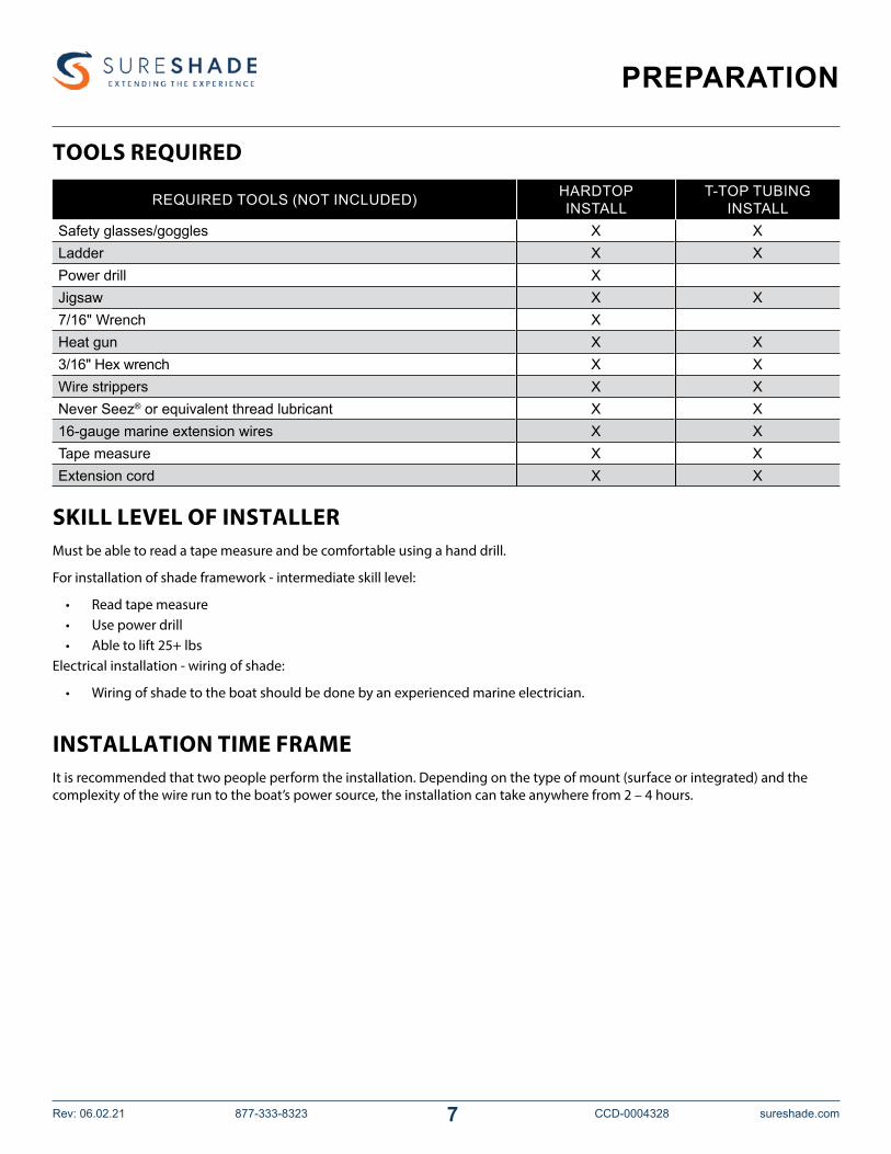
TOOLS REQUIRED
REQUIRED TOOLS (NOT INCLUDED) HARDTOP INSTALL
T-TOP TUBING INSTALL
Safety glasses/goggles X XLadder X XPower drill XJigsaw X X7/16" Wrench XHeat gun X X3/16" Hex wrench X XWire strippers X XNever Seez® or equivalent thread lubricant X X16-gauge marine extension wires X XTape measure X XExtension cord X X
SKILL LEVEL OF INSTALLERMust be able to read a tape measure and be comfortable using a hand drill.
For installation of shade framework - intermediate skill level:
• Read tape measure• Use power drill• Able to lift 25+ lbs
Electrical installation - wiring of shade:
• Wiring of shade to the boat should be done by an experienced marine electrician.
INSTALLATION TIME FRAMEIt is recommended that two people perform the installation. Depending on the type of mount (surface or integrated) and the complexity of the wire run to the boat’s power source, the installation can take anywhere from 2 – 4 hours.
8 sureshade.com Rev: 06.02.21877-333-8323 CCD-0004328
INSTALLATION
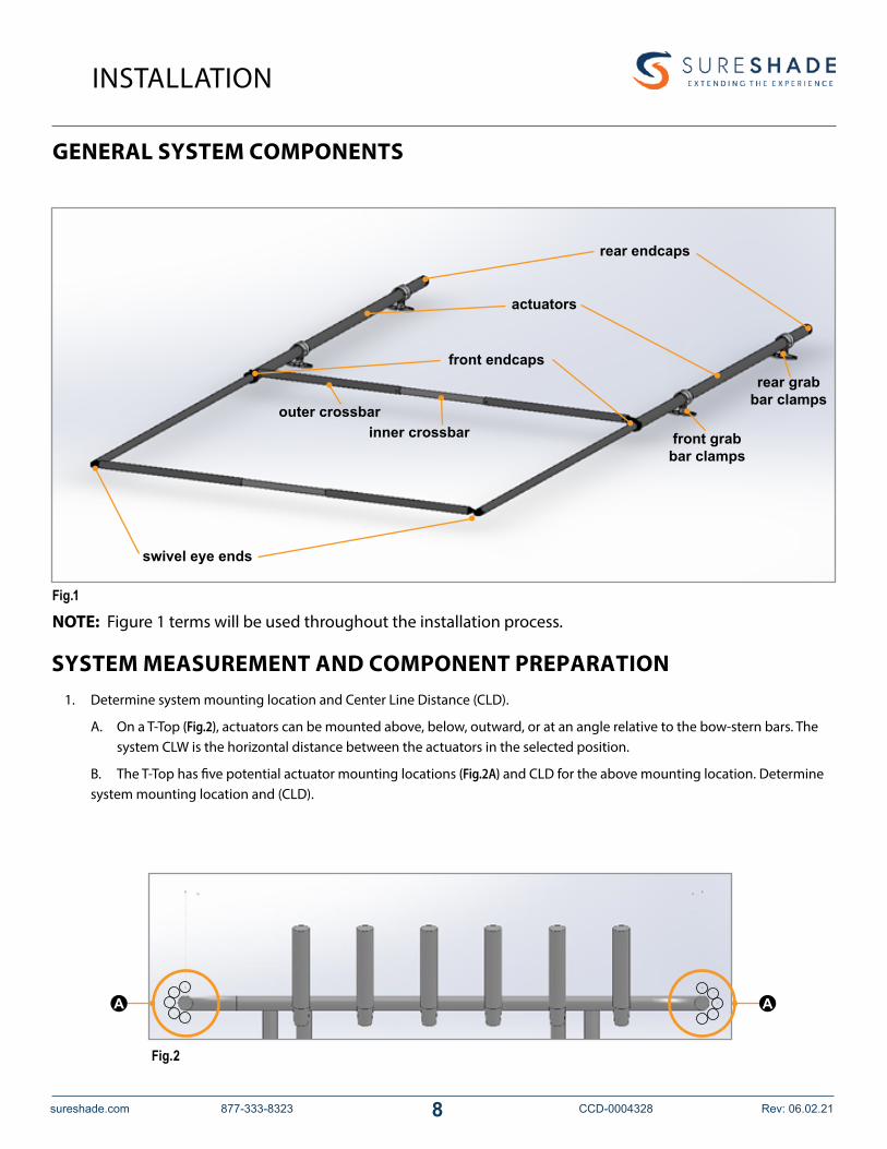
GENERAL SYSTEM COMPONENTS
NOTE: Figure 1 terms will be used throughout the installation process.
Fig.1
SYSTEM MEASUREMENT AND COMPONENT PREPARATION1. Determine system mounting location and Center Line Distance (CLD).
A. On a T-Top (Fig.2), actuators can be mounted above, below, outward, or at an angle relative to the bow-stern bars. The system CLW is the horizontal distance between the actuators in the selected position.
B. The T-Top has five potential actuator mounting locations (Fig.2A) and CLD for the above mounting location. Determine system mounting location and (CLD).
Fig.2
outer crossbarinner crossbar
front endcaps
swivel eye ends
actuators
rear endcaps
rear grab bar clamps
front grab bar clamps
A A

9 Rev: 06.02.21 sureshade.com877-333-8323 CCD-0004328
INSTALLATION
aft
port
forward/bow
starboard
mounting clamps
6" - 12" > = 26"
HARDTOP ACTUATOR MOUNTING 1. With (CLD) acquired, mark the location for the two front mounts (Fig.4).
NOTE: In this instance the front mounts are oriented toward the aft of the vessel. This location should be half the (CLD) from the center of the hardtop to the center of the mount.
Fig.3
1/2 CLD1/2 CLD
center of hardtop
center of mid mount center of mid mount
bow
aft
front mount
front mount
C. On a hard top (Fig.2), actuators can be mounted above or below the top. The system CLD is the horizontal distance between the actuators in the selected position.
Fig.4

10 sureshade.com Rev: 06.02.21877-333-8323 CCD-0004328
INSTALLATION
Fig.5
Fig.6
2. At the locations marked in the previous step drill two clearance holes for1/4"-20 X 1 1/2" bolts at each grab bar clamp as shown below (Fig. 5). Loosely install mounting hardware (not included) to hold in place.
3. Place the two rear grab bar clamps on the hard top and slide actuators into the clamps. Confirm that the CLD is the same for these two mounts before drilling additional holes. Once confirmed, drill holes and loosely install mounting hardware (not included) to hold in place.
bolt locations

11 Rev: 06.02.21 sureshade.com877-333-8323 CCD-0004328
INSTALLATION
location of crossbar
Fig.7
4. Confirm that the from end cap is past the aft most component of the hardtop. It is important that there is a direct path between the two front endcaps. In subsequent steps the crossbar will be installed in this location (Fig. 7).
Fig.8
5. Install the inner crossbar first using two of the provided 1/4"-20 X 1 1/2" socket head cap screws and two of the provided 1/4"-20 nylon locking nuts.
A. Set a nylon locking nut into each top hex pocket (Fig.8A).
B. Install each socket head cap screw from the bottom of the front end cap (Fig.8B).
C. On the other side, only loosely install hardware to confirm alignment. Do NOT tighten screws. One side of the crossbar will need to be removed to install the canvas.
NOTE: Make sure thread lubricant is used on the hardware. The front end caps have a top and bottom, the bottom of the front end cap has a boss so that the crossbar swivel cannot be installed upside down. If the ridge is interfering with installation, rotate the actuators 180 degrees so that the ridge is facing the floor of the boat.
A
B

12 sureshade.com Rev: 06.02.21877-333-8323 CCD-0004328
Fig.9
set screw location
mounting screw locations
6. At this point tighten the pre-installed set screws in each of the 4 grab bar clamps, and tighten all 8 of the mounting screws which were left loose up until this point.
NOTE: The following section, T-Top Actuator Mounting, is required only for T-TOP mounting. To continue with hardtop mounting, go to the Securing the Crossbars and Installing Canvas section.
INSTALLATION

13 Rev: 06.02.21 sureshade.com877-333-8323 CCD-0004328
Fig.10
INSTALLATION
T-TOP ACTUATOR MOUNTING1. Insert the tubing adapter on the T-Top frame and loosely affix the mid-mount using two 1/4"-20 X 1 1/2" bolts (Fig.10A).
NOTE: Available clearance between the T-Top’s canvas and frame may require that the mount can be installed at an angle instead of vertically above or below the frame.
2. Loosely affix the top mount component using one 1/4"-20 X 1 1/2" bolt (Fig.11A). The clamp should be rotated to open the actuator pocket for subsequent installation steps.
Fig.11 3. Repeat steps 1 and 2 for the remaining three mounts.
A
A
A

14 sureshade.com Rev: 06.02.21877-333-8323 CCD-0004328
INSTALLATION
4. Place the actuators into the mounts (Fig.12). With the actuator inserted, rotate the actuator mount to close the pocket. Install the remaining 1/4"-20 X 1 1/2" bolt on each mount, but do NOT tighten.
5. Make sure the actuators are oriented properly. The boss on the front end cap should be oriented down toward the deck (Fig.13).
Fig.12
Fig.13
boss on front end cap

15 Rev: 06.02.21 sureshade.com877-333-8323 CCD-0004328
INSTALLATION
6. Install the inner crossbar first using two of the provided 1/4"-20 X 1 1/2"socket head cap screws and two of the provided 1/4"-20 nylon locking nuts.A. Set a nylon locking nut into each top hex pocket (Fig.14A).
B. Install each socket head cap screw from the bottom of the front end cap (Fig.14B).
NOTE: Only install one side at this time so that the canvas can be installed without disassembly. Make sure thread lubricant is used
7. With the inner crossbar in place, secure all mounting hardware then proceed to canvas installation.
Fig.14
A
B

16 sureshade.com Rev: 06.02.21877-333-8323 CCD-0004328
INSTALLATION
Fig.16
SECURING THE CROSSBARS AND INSTALLING CANVAS1. Slide the large loop in the canvas over the inner crossbar, then install the free end of the crossbar to the front end
cap (Fig.15).
Fig.15
large canvas loopinner crossbar
webbing receiver
one support rib
2. Slide three cam locks onto each actuator. Orientation of the cam locks is important (Fig.16). The side of the cam lock should be oriented such that one support rib is facing up and the webbing receiver portion of the cam lock should be facing inward, towards the center of the system.

17 Rev: 06.02.21 sureshade.com877-333-8323 CCD-0004328
Fig.17
INSTALLATION
3. Slide the outer crossbar into the small canvas loop (Fig.17A), then install it to the actuator swivel eye ends (Fig.17B) using two self-locking implanted cotter (SLIC) pins (Fig.17C).
NOTE: Figure 17 shows the actuators extended. During installation, the actuators can be left retracted to complete step 3.
A
B
C
Fig.18
4. Align the six cam locks with the corresponding webbing loops on the canvas (Fig.18).

18 sureshade.com Rev: 06.02.21877-333-8323 CCD-0004328
Fig.19
INSTALLATION
webbing outwebbing in
5. Loop canvas webbing through cam locks (Fig.19), then tension webbing snugly.
NOTE: Lack of tension on the webbing can cause the canvas to sag when in use. Excessive webbing tension puts stress on the actuators and can degrade system performance.
6. Tighten all mounting hardware.
7. Trim excess webbing. If necessary, melt ends of webbing to seal the ends.
ELECTRICAL CONNECTIONS 1. Mount the momentary rocker switch to the desired location on the boat’s console/helm.2. Install the DC converter. See Wiring Diagram. A. The DC converter will have four labeled leads; two input power leads, two output power leads. B. Connect the output leads to the supplied PTX switch. I. Connect the black output lead of the converter to the white switch lead. II. Connect the yellow output lead of the converter to the red switch lead. C. Next connect the input leads to boat power. I. Connect the black input lead of the converter to -12V. II. Connect the red input lead of the converter to +12V.3. Run extension wires (not included) from the actuator leads to the switch's location.NOTE: Use marine insulated wire only, 16 AWG or larger.4. Use the provided heat shrink solder connector to attach the extension wires to the actuator leads.NOTE: The heat shrink solder connectors only require the use of a heat gun for connection. A. Insert both stripped wire ends into the heat shrink solder connector until they make contact. B. Using a heat gun, apply constant and even heat to the entire heat shrink solder connector until the solder flows and
completely covers the stripped wire ends and the insulating jacket shrinks to make a solid connection completely around the two wires.
5. From each actuator there should be one red and one black extension wire that will be routed to the switch location. At the switch location:
A. Combine the two red extension wires into one heat shrink solder connector. B. Combine the two black extension wires into one heat shrink solder connector. C. Connect the two black extension wires to the single black switch wire. D. Connect the two red extension wires to the single green switch wire. E. Using a heat gun, apply constant and even heat to the connectors until the solder flows and completely covers the
stripped wire ends. F. Continue to apply heat until the insulating jackets shrink completely around the wires to make a solid connection.

19 Rev: 06.02.21 sureshade.com877-333-8323 CCD-0004328
MAINTENANCE
actuator
actuator
heat shrink solder connectors
extension wires
switch
+12V
-12V
dc converter
6. Connect the switch to DC power on the boat. The single red switch wire connects to +12V and the single white wire connects to -12V.
Reference Wiring Diagram for further detail.
SureShade recommends following basic care and maintenance of SureShade shade components to maintain peak performance and prolong the life of the sunshade system.
REGULAR CLEANINGWe recommend general freshwater washdown to remove built up of salt deposits as needed.
CANVASSureShade sunshade systems use Sunbrella® fabrics for canvas. SureShade recommends following Sunbrella’s basic canvas care and cleaning instructions to prolong the life of the canvas.
Basic canvas care includes:• General, light cleaning with a hose on a monthly basis with clear water to remove debris.• A thorough cleaning every 2-3 years, which may include fabric guard and/or mildew treatments.• Conduct an annual inspection of your canvas to ensure that all threading is intact.• A pull test on the thread to confirm that threading has not become dry-rotted from the elements.
LONG-TERM STORAGESureShade sunshade systems are built with quality marine-grade construction and materials. However, just like other parts of a boat, SureShade canvas systems need to be shielded from snow and other harsh winter weather conditions to protect the canvas and mechanical components. SureShade recommends taking the proper precautions to avoid damage during winter storage (or ground transportation for winter storage), which includes fully retracting and securing the SureShade sunshade system and properly tarping or shrink-wrapping the boat.
Many boaters transport their boats to a storage location or a warmer climate during the winter months. To ensure that the SureShade system is properly transported, and to avoid potential damage, visit www.sureshade.com/sureshade-ground-transportation-guide/.
Wiring Diagram

Manual information may be distributed as a complete document only, unless SureShade provides explicit consent to distribute individual parts. All manual information is subject to change without notice. Revised editions will be available for free
download at sureshade.com. Manual information is considered factual until made obsolete by a revised version. Please recycle all obsolete materials.
For all concerns or questions, please contactSureShade, a Lippert Components Company
Ph: (877) 333-8323 | Web: sureshade.com | Email: [email protected]
© Copyright 2020 Lippert Components, Inc. dba SureShade®
Troubleshooting Chart
What is happening?What is happening? Why?Why? What should be done?What should be done?
Shade does not extend/retract when switch is pressed.
Boat power not available. Check power with multimeter. Make sure batteries are charged.
Incorrectly wired. Make sure proper gauge wires are used. Look for loose connections.
Voltage drop when extending/retracting shade.
Batteries not fully charged. Make sure batteries are fully charged.Incorrect wire gauge used. Make sure proper gauge wires are used.Loose wiring connections. Make sure all connections are tight.
System does not fully open/close.
Motor/mechanical malfunction. Contact www.sureshade.com
Canvas is sagging when fully extended.
Not enough tension in canvas. Tighten canvas tensioners.
NOTE: System may back drive slightly while underway, this is normal. Simply press extend on the switch to restore the system to its full extended state.