Embed Size (px)
Citation preview
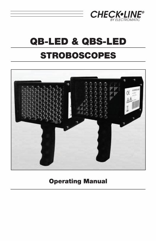
CHECK•LINE®
BY ELECTROMATIC
QB-LED & QBS-LEDSTROBOSCOPES
Operating Manual
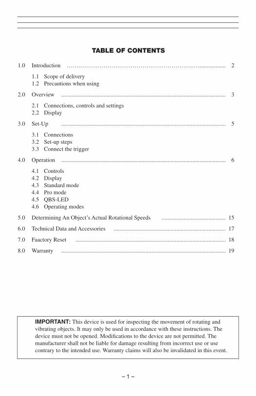
TABLE OF CONTENTS
1.0 Introduction ………………………………………………………..… ................... 02
1.1 Scope of delivery 1.2 Precautions when using
2.0 Overview ................................................................................................................. 03
2.1 Connections, controls and settings 2.2 Display
3.0 Set-Up ................................................................................................................. 05
3.1 Connections 3.2 Set-up steps 3.3 Connect the trigger
4.0 Operation ................................................................................................................. 06
4.1 Controls 4.2 Display 4.3 Standard mode 4.4 Pro mode 4.5 QBS-LED 4.6 Operating modes
5.0 Determining An Object’s Actual Rotational Speeds ............................................ 15
6.0 Technical Data and Accessories ............................................................................. 17
7.0 Faactory Reset ....................................................................................................... 18
8.0 Warranty ................................................................................................................. 19
IMPORTANT: This device is used for inspecting the movement of rotating and vibrating objects. It may only be used in accordance with these instructions. The device must not be opened. Modifications to the device are not permitted. The manufacturer shall not be liable for damage resulting from incorrect use or use contrary to the intended use. Warranty claims will also be invalidated in this event.
– 1 –
– 2 –
1.0 INTRODUCTION
The Check-Line QB-LED is a hand-held, battery-powered stroboscope featuring extremely bright LEDs for the highest light output in its class. Designed for machinery observation, visual inspection and motion analysis, its robust design is suitable for use in the toughest industrial environments.
1.1 Scope of Delivery
Check that you have received all of the following:
• Stroboscope: QB-LED design (40 LEDs, no laser) or QBS-LED design (118 LEDs, with laser) • Operating instructions • Calibration certificate • Charger with connector set • Trigger plug • Reflective tapes (QBS-LED only) • Handle • Foam-fitted, plastic carrying case
Note: This device is suitable for use in residential, commercial and industrial area.
1.2 Precautions when using
Risk of injury! Laser class 2: The stroboscope QBS-LED is fitted with a class 2 laser. This is located at the front of the device. The laser beam can damage eyes. For this reason, do not stare directly at the laser beam and never direct it at people or animals. Wavelength: 650 nm, output: 1 mW.
Risk of Injury! Flashing lights can cause retina damage: The stroboscope QB-LED and QBS-LED versions are fitted with 40/118 LEDs respectively. These produce potentially dangerous optical radiation, which can cause retina damage. Do not stare directly at the light and never direct it at people or animals.
Risk of injury! Moving objects appear still or in slow motion in stroboscopic light. Do not touch such objects under any circumstance.
Risk of injury! The device may not be used in potentially explosive areas.
Risk of injury! Stroboscopic light can trigger epileptic seizures in persons at risk.
– 3 –
2.0 OVERVIEW
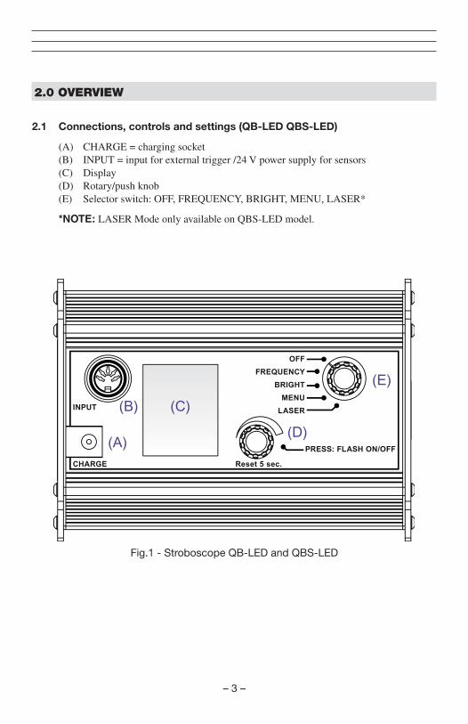
2.1 Connections, controls and settings (QB-LED QBS-LED)
(A) CHARGE = charging socket (B) INPUT = input for external trigger /24 V power supply for sensors (C) Display (D) Rotary/push knob (E) Selector switch: OFF, FREQUENCY, BRIGHT, MENU, LASER*
*NOTE: LASER Mode only available on QBS-LED model.
OFF
FREQUENCY
BRIGHT
MENU
LASER
PRESS: FLASH ON/OFF
Reset 5 sec.CHARGE
INPUT
(A)
(E)
(D)
(B) (C)
Fig.1 - Stroboscope QB-LED and QBS-LED
– 4 –
(1) (2) (3)
(4)
(5)
(6) (7)
(8) (9)
(10) (11)
(12) (13)
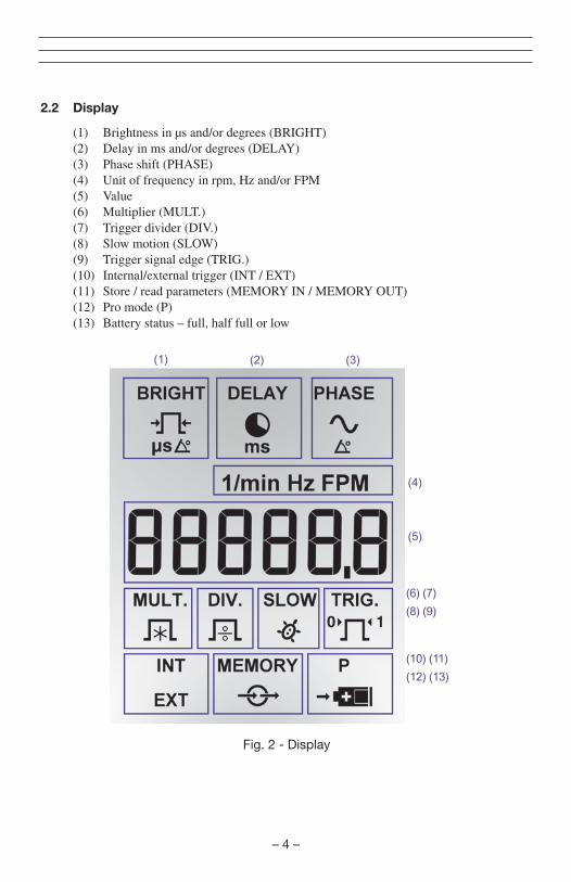
2.2 Display
(1) Brightness in μs and/or degrees (BRIGHT) (2) Delay in ms and/or degrees (DELAY) (3) Phase shift (PHASE) (4) Unit of frequency in rpm, Hz and/or FPM (5) Value (6) Multiplier (MULT.) (7) Trigger divider (DIV.) (8) Slow motion (SLOW) (9) Trigger signal edge (TRIG.) (10) Internal/external trigger (INT / EXT) (11) Store / read parameters (MEMORY IN / MEMORY OUT) (12) Pro mode (P) (13) Battery status – full, half full or low
Fig. 2 - Display
– 5 –
3.0 SETUP
3.1 Connectors (see Fig. 1)
3.2 Set-up steps
Please follow the steps below when setting up the device:
1. Charge the device by plugginh the charger into the CHARGE (A) socket to the rear of the device (see Fig. 1)
2. Direct the device at a moving object and switch it on. Turn the selector switch (E) one notch to the left to “FREQUENCY.”
The device will start to flash immediately. For this reason, do not direct it at people or animals.
NOTE: The device will flash at the frequency that was set most recently. The display shows the selected flash frequency in the unit that was set most recently (rpm, Hz or FPM). If the flash frequency coincides with the frequency of the motion, a static image appears.
3.3 Connect the trigger
The device has the option of being externally triggered.
DO NOT trigger the device with signals in excess or 300,000 FPM. Material damage may occur.
NOTE: Use only original material from the manufacturer to connect the trigger signal.
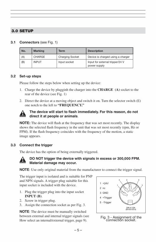
The trigger input is isolated and is suitable for PNP and NPN signals. A trigger plug suitable for this input socket is included with the device.
1. Plug the trigger plug into the input socket INPUT (B). 2. Screw in trigger plug. 3. Assign the connection socket as per Fig. 3.
NOTE: The device must be manually switched between external and internal trigger signals (see How select an internal/external trigger, page 9).
(EN 60130-9)
1
5
3
2 nc
3 GND
5 -Trigger
Fig. 3 - Assignment of the connection socket.
No. Marking Term Description
(A) CHARGE Charging Socket Device is charged using a charger
(B) INPUT Input socket Input for external tripper/24 V power supply
– 6 –
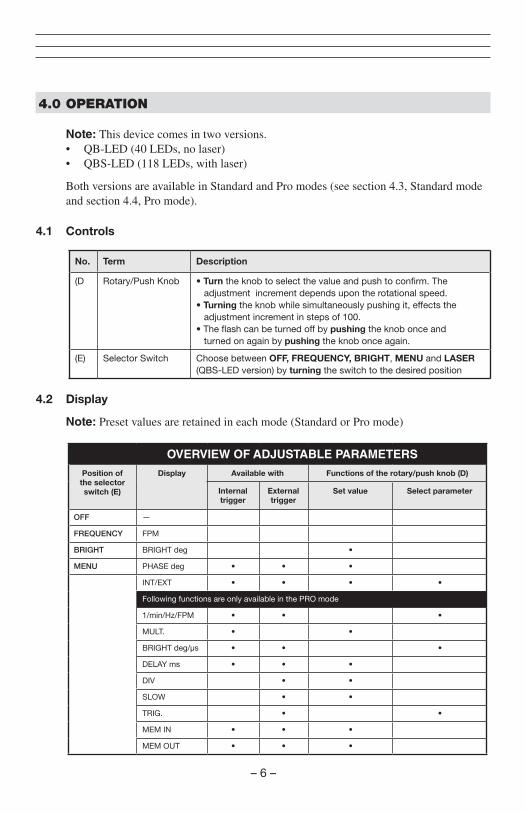
4.0 OPERATION
Note: This device comes in two versions. • QB-LED (40 LEDs, no laser) • QBS-LED (118 LEDs, with laser)
Both versions are available in Standard and Pro modes (see section 4.3, Standard mode and section 4.4, Pro mode).
4.1 Controls
No. Term Description
(D Rotary/Push Knob • Turn the knob to select the value and push to confirm. The adjustment increment depends upon the rotational speed. • Turning the knob while simultaneously pushing it, effects the adjustment increment in steps of 100. • The flash can be turned off by pushing the knob once and turned on again by pushing the knob once again.
(E) Selector Switch Choose between OFF, FREQUENCY, BRIGHT, MENU and LASER (QBS-LED version) by turning the switch to the desired position
4.2 Display
Note: Preset values are retained in each mode (Standard or Pro mode)
OVERVIEW OF ADJUSTABLE PARAMETERSPosition of the selector switch (E)
Display Available with Functions of the rotary/push knob (D)
Internal trigger
External trigger
Set value Select parameter
OFF —
FREQUENCY FPM
BRIGHT BRIGHT deg •
MENU PHASE deg • • •
INT/EXT • • • •
Following functions are only available in the PRO mode
1/min/Hz/FPM • • •
MULT. • •
BRIGHT deg/µs • • •
DELAY ms • • •
DIV • •
SLOW • •
TRIG. • •
MEM IN • • •
MEM OUT • • •
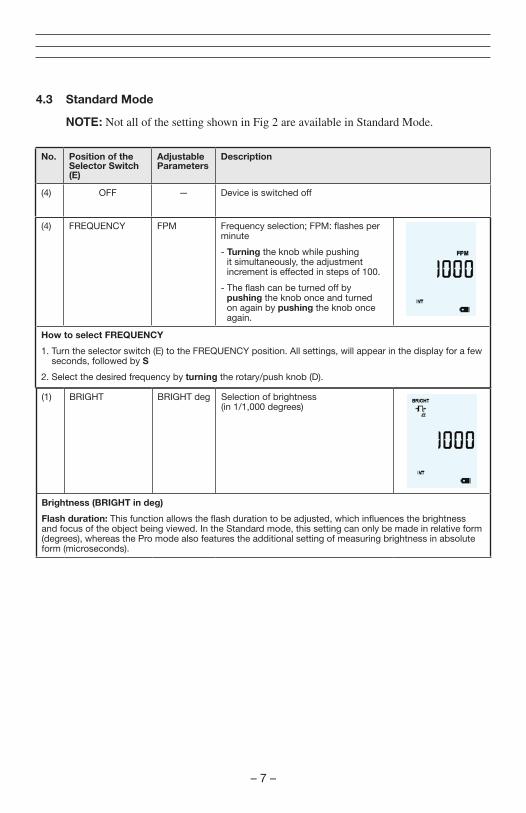
(4) FREQUENCY FPM Frequency selection; FPM: flashes per minute
- Turning the knob while pushing it simultaneously, the adjustment increment is effected in steps of 100.
- The flash can be turned off by pushing the knob once and turned on again by pushing the knob once again.
How to select FREQUENCY
1. Turn the selector switch (E) to the FREQUENCY position. All settings, will appear in the display for a few seconds, followed by S
2. Select the desired frequency by turning the rotary/push knob (D).
– 7 –
4.3 Standard Mode
NOTE: Not all of the setting shown in Fig 2 are available in Standard Mode.
No. Position of the Selector Switch (E)
Adjustable Parameters
Description
(4) OFF — Device is switched off
(1) BRIGHT BRIGHT deg Selection of brightness (in 1/1,000 degrees)
Brightness (BRIGHT in deg)
Flash duration: This function allows the flash duration to be adjusted, which influences the brightness and focus of the object being viewed. In the Standard mode, this setting can only be made in relative form (degrees), whereas the Pro mode also features the additional setting of measuring brightness in absolute form (microseconds).
– 8 –
No. Position of the Selector Switch (E)
Adjustable Parameters
Description Display
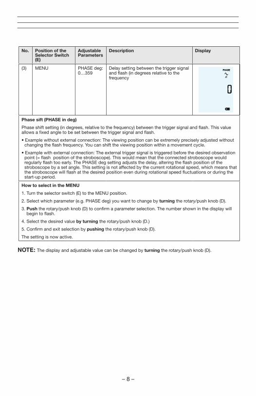
(3) MENU PHASE deg: 0…359
Delay setting between the trigger signal and flash (in degrees relative to the frequency
Phase sift (PHASE in deg)
Phase shift setting (in degrees, relative to the frequency) between the trigger signal and flash. This value allows a fixed angle to be set between the trigger signal and flash.
• Example without external connection: The viewing position can be extremely precisely adjusted without changing the flash frequency. You can shift the viewing position within a movement cycle.
• Example with external connection: The external trigger signal is triggered before the desired observation point (= flash position of the stroboscope). This would mean that the connected stroboscope would regularly flash too early. The PHASE deg setting adjusts the delay, altering the flash position of the stroboscope by a set angle. This setting is not affected by the current rotational speed, which means that the stroboscope will flash at the desired position even during rotational speed fluctuations or during the start-up period.
How to select in the MENU
1. Turn the selector switch (E) to the MENU position.
2. Select which parameter (e.g. PHASE deg) you want to change by turning the rotary/push knob (D).
3. Push the rotary/push knob (D) to confirm a parameter selection. The number shown in the display will begin to flash.
4. Select the desired value by turning the rotary/push knob (D.)
5. Confirm and exit selection by pushing the rotary/push knob (D).
The setting is now active.
NOTE: The display and adjustable value can be changed by turning the rotary/push knob (D).
– 9 –
No. Position of the Selector Switch (E)
Adjustable Parameters
Description Display
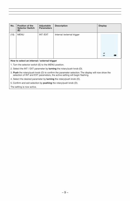
(10) MENU INT /EXT Internal /external trigger
How to select an internal / external trigger
1. Turn the selector switch (E) to the MENU position.
2. Select the INT / EXT parameter by turning the rotary/push knob (D).
3. Push the rotary/push knob (D) to confirm the parameter selection. The display will now show the selection of INT and EXT parameters, the active setting will begin flashing.
4. Select the desired parameter by turning the rotary/push knob (D).
5. Confirm and exit selection by pushing the rotary/push knob (D).
The setting is now active.
– 10 –
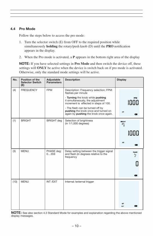
4.4 Pro Mode
Follow the steps below to access the pro mode:
1. Turn the selector switch (E) from OFF to the required position while simultaneously holding the rotary/push knob (D) until the PRO notification appears in the display.
2. When the Pro mode is activated, a P appears in the bottom right area of the display
NOTE: If you have selected settings in Pro Mode and then switch the device off, these settings will ONLY be active when the device is switch back on if pro mode is activated. Otherwise, only the standard mode settings will be active.
No. Position of the Selector Switch (E)
Adjustable Parameters
Description Display
(4) FREQUENCY FPM Description: Frequency selection; FPM: flashes per minute
- Turning the knob while pushing it simultaneously, the adjustment increment is effected in steps of 100.
- The flash can be turned off by pushing the knob once and turned on again by pushing the knob once again.
(1) BRIGHT BRIGHT deg Selection of brightness (in 1/1,000 degrees)
(3) MENU PHASE deg: 0…359
Delay setting between the trigger signal and flash (in degrees relative to the frequency
(10) MENU INT /EXT Internal /external trigger
NOTE: See also section 4.3 Standard Mode for examples and explanation regarding the above mentioned display messages.
–11–
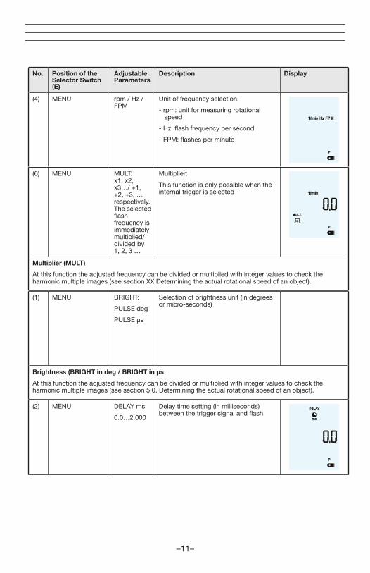
(6) MENU MULT: x1, x2, x3…/ +1, +2, +3, … respectively. The selected flash frequency is immediately multiplied/divided by 1, 2, 3 …
Multiplier:
This function is only possible when the internal trigger is selected
Multiplier (MULT)
At this function the adjusted frequency can be divided or multiplied with integer values to check the harmonic multiple images (see section XX Determining the actual rotational speed of an object).
No. Position of the Selector Switch (E)
Adjustable Parameters
Description Display
(4) MENU rpm / Hz / FPM
Unit of frequency selection:
- rpm: unit for measuring rotational speed
- Hz: flash frequency per second
- FPM: flashes per minute
(1) MENU BRIGHT:
PULSE deg
PULSE µs
Selection of brightness unit (in degrees or micro-seconds)
Brightness (BRIGHT in deg / BRIGHT in µs
At this function the adjusted frequency can be divided or multiplied with integer values to check the harmonic multiple images (see section 5.0, Determining the actual rotational speed of an object).
(2) MENU DELAY ms:
0.0…2.000
Delay time setting (in milliseconds) between the trigger signal and flash.
–12–
No. Position of the Selector Switch (E)
Adjustable Parameters
Description Display
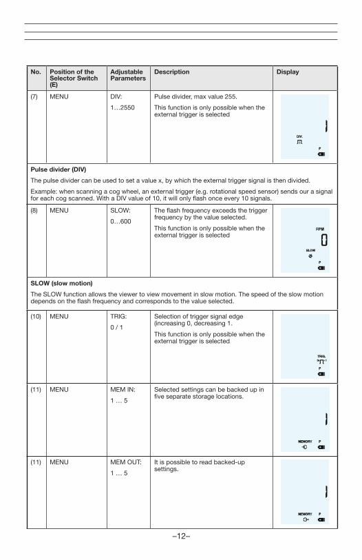
(7) MENU DIV:
1…2550
Pulse divider, max value 255.
This function is only possible when the external trigger is selected
Pulse divider (DIV)
The pulse divider can be used to set a value x, by which the external trigger signal is then divided.
Example: when scanning a cog wheel, an external trigger (e.g. rotational speed sensor) sends our a signal for each cog scanned. With a DIV value of 10, it will only flash once every 10 signals.
(8) MENU SLOW:
0…600
The flash frequency exceeds the trigger frequency by the value selected.
This function is only possible when the external trigger is selected
SLOW (slow motion)
The SLOW function allows the viewer to view movement in slow motion. The speed of the slow motion depends on the flash frequency and corresponds to the value selected.
(10) MENU TRIG:
0 / 1
Selection of trigger signal edge (increasing 0, decreasing 1.
This function is only possible when the external trigger is selected
(11) MENU MEM IN:
1 … 5
Selected settings can be backed up in five separate storage locations.
(11) MENU MEM OUT:
1 … 5
It is possible to read backed-up settings.
–13 –
No. Position of the Selector Switch (E)
Adjustable Parameters
Description Display
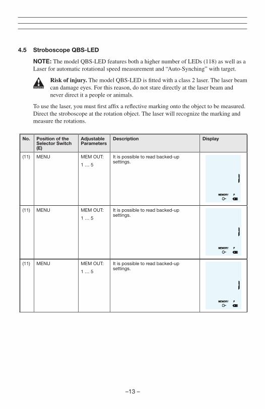
(11) MENU MEM OUT:
1 … 5
It is possible to read backed-up settings.
(11) MENU MEM OUT:
1 … 5
It is possible to read backed-up settings.
(11) MENU MEM OUT:
1 … 5
It is possible to read backed-up settings.
4.5 Stroboscope QBS-LED
NOTE: The model QBS-LED features both a higher number of LEDs (118) as well as a Laser for automatic rotational speed measurement and “Auto-Synching” with target.
Risk of injury. The model QBS-LED is fitted with a class 2 laser. The laser beam can damage eyes. For this reason, do not stare directly at the laser beam and never direct it a people or animals.
To use the laser, you must first affix a reflective marking onto the object to be measured. Direct the stroboscope at the rotation object. The laser will recognize the marking and measure the rotations.
–14 –
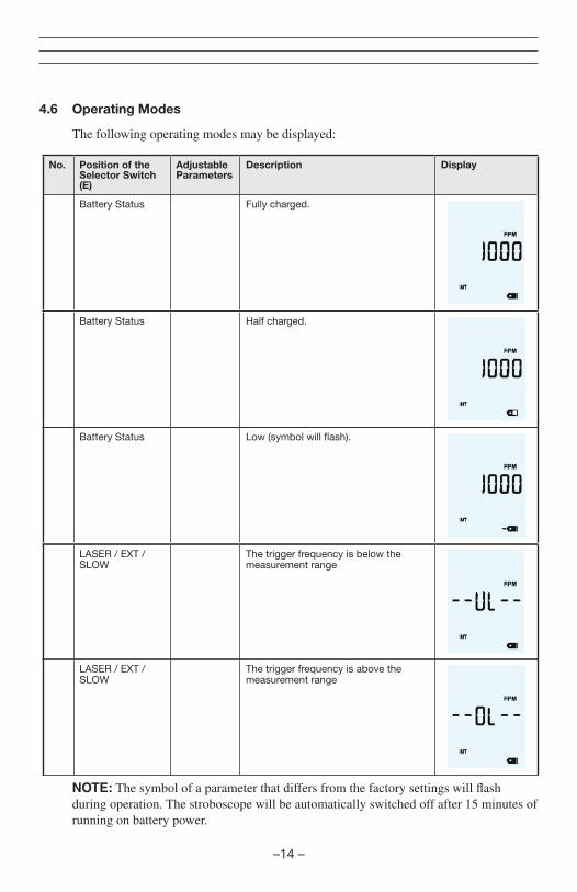
4.6 Operating Modes
The following operating modes may be displayed:
No. Position of the Selector Switch (E)
Adjustable Parameters
Description Display
Battery Status Fully charged.
Battery Status Half charged.
Battery Status Low (symbol will flash).
LASER / EXT / SLOW
The trigger frequency is below the measurement range
LASER / EXT / SLOW
The trigger frequency is above the measurement range
NOTE: The symbol of a parameter that differs from the factory settings will flash during operation. The stroboscope will be automatically switched off after 15 minutes of running on battery power.
–15 –
5.0 DETERMINING THE ROTATIONAL SPEED OF OBJECTS
The stroboscope can be used as a digital revolution indicator to determine an object’s actual rotational speed and/or the frequency of cyclical movements. The stroboscope does this by visually “freezing” the object’s movement and then taking a reading of the rotational speed or frequency from the LCD display. As is the case with all stroboscopes, it is vital to ensure that this “frozen” image is not a harmonic of the object’s actual rotational speed.
Useful information:
• It’s helpful to have a rough idea of the object’s rotational speed beforehand.
• Regular shaped objects, e.g. a fan with several vanes or a motor shaft, must be affixed with an identification marking (using color or a reflective strip etc.) in order to be able to differentiate its orientation of movement.
• A still image always appears exactly at integer division of the speed of the object’s actual rotational speed!
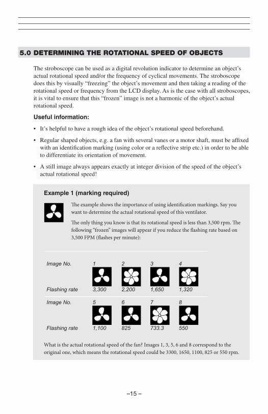
Example 1 (marking required)
The example shows the importance of using identification markings. Say you want to determine the actual rotational speed of this ventilator.
The only thing you know is that its rotational speed is less than 3,500 rpm. The following “frozen” images will appear if you reduce the flashing rate based on 3,500 FPM (flashes per minute):
What is the actual rotational speed of the fan? Images 1, 3, 5, 6 and 8 correspond to the original one, which means the rotational speed could be 3300, 1650, 1100, 825 or 550 rpm.
– 16 –
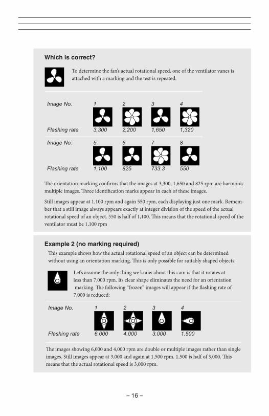
Which is correct?
Example 2 (no marking required)
To determine the fan’s actual rotational speed, one of the ventilator vanes is attached with a marking and the test is repeated.
This example shows how the actual rotational speed of an object can be determined without using an orientation marking. This is only possible for suitably shaped objects.
Let’s assume the only thing we know about this cam is that it rotates at less than 7,000 rpm. Its clear shape eliminates the need for an orientation marking. The following “frozen” images will appear if the flashing rate of 7,000 is reduced:
The images showing 6,000 and 4,000 rpm are double or multiple images rather than single images. Still images appear at 3,000 and again at 1,500 rpm. 1,500 is half of 3,000. This means that the actual rotational speed is 3,000 rpm.
The orientation marking confirms that the images at 3,300, 1,650 and 825 rpm are harmonic multiple images. Three identification marks appear in each of these images.
Still images appear at 1,100 rpm and again 550 rpm, each displaying just one mark. Remem-ber that a still image always appears exactly at integer division of the speed of the actual rotational speed of an object. 550 is half of 1,100. This means that the rotational speed of the ventilator must be 1,100 rpm
Image No. 1 2 3 4
Flashing rate 6.000 4.000 3.000 1.500
– 17 –
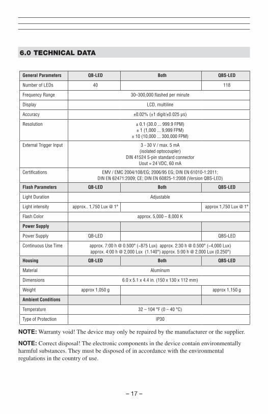
6.0 TECHNICAL DATA
NOTE: Warranty void! The device may only be repaired by the manufacturer or the supplier.
NOTE: Correct disposal! The electronic components in the device contain environmentally harmful substances. They must be disposed of in accordance with the environmental regulations in the country of use.
General Parameters QB-LED Both QBS-LED
Number of LEDs 40 118
Frequency Range 30–300,000 flashed per minute
Display LCD, multiline
Accuracy ±0.02% (±1 digit/±0.025 µs)
Resolution ± 0.1 (30.0 ... 999.9 FPM) ± 1 (1,000 ... 9,999 FPM)
± 10 (10,000 ... 300,000 FPM)
External Trigger Input 3 - 30 V / max. 5 mA (isolated optocoupler)
DIN 41524 5-pin standard connector Uout = 24 VDC, 60 mA
Certifications EMV / EMC 2004/108/EG; 2006/95 EG; DIN EN 61010-1:2011; DIN EN 62471:2009; CE; DIN EN 60825-1:2008 (Version QBS-LED)
Flash Parameters QB-LED Both QBS-LED
Light Duration Adjustable
Light intensity approx.. 1,750 Lux @ 1° approx 1,750 Lux @ 1°
Flash Color approx. 5,000 – 8,000 K
Power Supply
Power Supply QB-LED QBS-LED
Continuous Use Time approx. 7:00 h @ 0.500° (~875 Lux) approx. 2:30 h @ 0.500° (~4,000 Lux) approx. 4:00 h @ 2,000 Lux (1.140°) approx. 5:00 h @ 2,000 Lux (0.250°)
Housing QB-LED Both QBS-LED
Material Aluminum
Dimensions 6.0 x 5.1 x 4.4 in. (150 x 130 x 112 mm)
Weight approx 1,050 g approx 1,150 g
Ambient Conditions
Temperature 32 – 104 °F (0 – 40 °C)
Type of Protection IP30

–18 –
7.0 FACTORY RESET
To reset the factory settings, press and hold the rotary/push knob (D) for at least 5 seconds
– 19 –
8.0 WARRANTY
ELECTROMATIC Equipment Co., Inc. (ELECTROMATIC) warrants to the original purchaser that this product is of merchantable quality and confirms in kind and quality with the descriptions and specifications thereof. Product failure or malfunction arising out of any defect in workmanship or material in the product existing at the time of delivery thereof which manifests itself within one year from the sale of such product, shall be remedied by repair or replacement of such product, at ELECTROMATIC’s option, except where unauthorized repair, disassembly, tampering, abuse or misapplication has taken place, as determined by ELECTROMATIC. All returns for warranty or non-warranty repairs and/or replacement must be authorized by ELECTROMATIC, in advance, with all repacking and shipping expenses to the address below to be borne by the purchaser.
THE FOREGOING WARRANTY IS IN LIEU OF ALL OTHER WARRANTIES, EXPRESSED OR IMPLIED, INCLUDING BUT NOT LIMITED TO, THE WARRANTY OF MERCHANTABILITY AND FITNESS FOR ANY PARTICULAR PURPOSE OR APPLICATION. ELECTROMATIC SHALL NOT BE RESPONSIBLE NOR LIABLE FOR ANY CONSEQUENTIAL DAMAGE, OF ANY KIND OR NATURE, RESULTING FROM THE USE OF SUPPLIED EQUIPMENT, WHETHER SUCH DAMAGE OCCURS OR IS DISCOVERED BEFORE, UPON OR AFTER REPLACEMENT OR REPAIR, AND WHETHER OR NOT SUCH DAMAGE IS CAUSED BY MANUFACTURER’S OR SUPPLIER’S NEGLIGENCE WITHIN ONE YEAR FROM INVOICE DATE.
Some State jurisdictions or States do not allow the exclusion or limitation of incidental or consequential damages, so the above limitation may not apply to you. The duration of any implied warranty, including, without limitation, fitness for any particular purpose and merchantability with respect to this product, is limited to the duration of the foregoing warranty. Some states do not allow limitations on how long an implied warranty lasts but, not withstanding, this warranty, in the absence of such limitations, shall extend for one year from the date of invoice.
ELECTROMATIC Equipment Co., Inc. 600 Oakland Ave. Cedarhurst, NY 11516—USA Tel: 1-800-645-4330/ Tel: 516-295-4300/ Fax: 516-295-4399
Every precaution has been taken in the preparation of this manual. Electromatic Equipment Co., Inc., assumes no responsibility for errors or omissions. Neither is any liability assumed for damages resulting from the use of information contained herein. Any brand or product names mentioned herein are used for identification purposes only, and are trademarks or registered trademarks of their respective holders.

–20 –
NOTES

ELECTROMATIC E Q U I P M E N T C O . , I N C .
600 Oakland Ave., Cedarhurst, NY 11516 – USA TEL: 516-295-4300 • FAX: 516-295-4399
CHECK•LINE®
INSTRUMENTS