Embed Size (px)
Citation preview

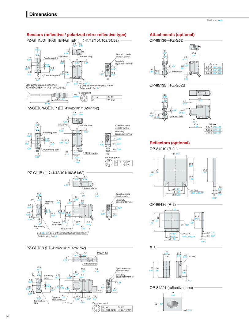
NEW Self-contained Threaded Sensors
PZ-G Series
MEGA POWERLong-range detection twice as far as conventional models
EASY ADJUSTMENTThe front light-receiving indicator allows easy optical axis alignment
EASY INSTALLATIONA one-touch mounting bracket makes screws unnecessary

2
Thrubeam type PZ-G51
High-power thrubeam type PZ-G52
Reflective type PZ-G41
Retro-reflective type PZ-G61
Detecting distance: 20m(65.6')
Detecting distance: 40m(131.2')
Detecting distance: 1m(3.3')
Detecting distance: 4.2m(13.8')
MEGA POWER
Dramatically improved performance and ease-of-use
* Compared with our conventional models
4-element red LED-type
2 times* longer detecting distance
2 times* faster response speed
* Compared with our conventional models
4 times* longer detecting distance
2 times* faster response speed
Self-contained Threaded Sensors PZ-G Series
A 4-element LED is used in upper-level fiber sensors because its wavelength can be easily observed by the human eye and the intensity change over time is small.
High-Power Dual LED-type
The high-intensity 4-element red LED has greatly improved the detecting distance. The bright beam spot makes it easy to align the optical axis.

3
Can be attached with an M18 nut
Can be attached with two M3 screws
Alignment indicator takes the guesswork out of long distance sensor setup
A variety of mounting styles are available to adapt to your application.
Laser Marked tags eliminate possible contaminationAll information (model#, lot#, etc.) is laser marked directly onto the sensor housing. There are no labels, inks or paints to peel or chip off into your products.
Has your receiver been bumped out of alignment? How can you tell?Thrubeam PZ-G models feature a bright red LED indicator that alerts you the instant proper alignment has been obtained. This simple yet crucial feature allows you to troubleshoot setup and run-time issues quickly, before they can snowball into major problems.
Easy-to-see blue trimmerEnhances operation efficiency
Slide it through
One-Touch mounting brackets cut installation timeOur unique one-touch brackets can save you and your customers considerable man-hours during installation or replacement.
Rectangular models
Rectangular models
Just push until it clicks
Just push until it clicks
Slide it through
Threaded models
Threaded models
EASY ADJUSTMENT
EASY INSTALLATION

4
Bipolar output typePZ-G**(C)B
Blue (Pin 3)
Brown (Pin1)
M12 connector
Black (Pin 4)
DC10−30V
PNP control output
0V
NPN control outputWhite (Pin 2)
1
2
4
3
Bipolar output (NPN+PNP) compatible with any input deviceThreaded models feature bipolar outputs (NPN and PNP), eliminating the need to stock sensors for both outputs.
19 types of mounting brackets provide a variety of mounting methodsA bracket can be selected according to the installation conditions. 19 types, including a one-touch bracket, are available.
Sen
sor m
ain
circ
uit
Ove
rcur
rent
prot
ectio
n ci
rcui
t
Differentiating the number of sheets
Different frequency beam
Ambient light
The interference suppression function prevents interference from nearby unitsWith thrubeam models, up to two sensors can be mounted in close proximity. Four sensors can be used by alternating the transmitter/ receiver position.
High-speed targets can be detected at a response speed of up to 500 µsA high-speed response of up to 500 µs, twice as fast as our conventional models, ensures detection on a high-speed line. The high power ensures stable detection.
The different frequency function automatically shifts the emission cycle if ambient light is received by the receiver.
The mounting brackets shown above are only part of the lineup. See page 7 for further details.
PUR cable
Threaded typeM12 connector
Rectangular typeM8 connector
Our oil-resistant cable ensures reliable operation in an oily environmentIn addition to the standard PVC cable, an oil-resistant PUR cable is available for use in harsh environments.
Standard M8 and M12 quick-disconnects make replacement easierThe PZ-G features a standard pin-out, which allows it to be a drop-in replacement with existing wiring.
Enhanced user-friendliness
PUR: Polyuretane

5
Thrubeam The long-range high-power beam makes it easy to align the optical axis
The visible spot makes it easy to align the optical axis
High-power long-range detection
Standard PZ-G51High-power PZ-G52
Retro-reflectiveStandard PZ-G61 (with P. R. O. function) Transparent object detection type PZ-G62
Reflective
Diffuse reflective PZ-G41 (long-range) PZ-G42 (short-range)
Narrow-view reflective type PZ-G101 Definite reflective type PZ-G102
Rectangular modelsThreaded models
High-intensity 4-element red LED
Long-range detection
20m (65.6')Long-range detection
40m (131.2')
High-power dual IR LED
High-intensity 4-element red LED
High-intensity 4-element red LED
Single IR LED
High-intensity 4-element red LED
High-intensity 4-element red LED
P.R.O. functionThe P. R. O. function* cancels direct reflections from metallic or mirror surfaced targets, allowing the PZ-G to reliably detect metal targets.* Polarized Reflection Optics
DEX circuitThe PZ-G employs a DEX circuit* (patented) that greatly amplifies the slight light attenuation caused by transparent targets ensuring stable detection.* Difference Expansion
Alignment IndicatorClearly indicates when emitter/receiver are properly aligned.
Alignment IndicatorClearly indicates when emitter/receiver are properly aligned.
Short-range detection
300mm (11.81")
Short-range detection
200mm (7.87")
Detecting distance of
5 to 45 mm (0.20" to 1.77")
Long-range detection
1m (3.3')
Spot diameter of approx. 5 mm (0.20") at a
detecting distance of 100 mm (3.94")
Spot diameter of approx. 2 mm (0.08") at a
detecting distance of 40 mm (1.58")
Long-range detection
0.1 to 4.2 m (0.3' to 13.8')(When using R-2L)
Detecting distance
0.1 to 1 m (0.3' to 3.3')(When using R-2L)
Thrubea
Model features

6
Sensor head lineup / Model variations
Sensor head lineup
Model variations
PZ-G21
21
51
52
41
42
101
102
61
62
Bipolar(NPN+PNP)
PNP
NPN
PNP
NPN
PNP
NPNN
P
CN
CP
EN
EP
BCB
Rectangular models
Threaded models
Type
Transparentobjectdetection
Definite reflective
Narrow-view reflective
High-power
Standard
Design Detecting distanceModel variations
Cable*Light source (LED)
Rectangular
Threaded
Rectangular
Threaded
Rectangular
Threaded M12 connector
M8 connector
M12 connector
M8 connector
M12 connector
M8 connector
M12 connector
M8 connector
M12 connector
M8 connectorCable (2m 6.6')
Cable (2m 6.6')
Cable (2m 6.6')
Cable (2m 6.6')
Cable (2m 6.6')
Cable (2m 6.6')
Cable (2m 6.6')
Cable (2m 6.6')
Cable (2m 6.6')
Cable (2m 6.6')
Cable (2m 6.6')
Cable (2m 6.6')
Cable (2m 6.6')
Cable (2m 6.6')
Cable (2m 6.6')
Cable (2m 6.6')
Red
Infrared
Infrared x 2
PZ-G51PPZ-G51NPZ-G51CPPZ-G51CN
M12 pigtail quick disconnect
M12 pigtail quick disconnect
M12 pigtail quick disconnect
M12 pigtail quick disconnect
M12 pigtail quick disconnect
M12 pigtail quick disconnect
PZ-G51EPPZ-G51EN
20 m (65.6')
200 mm (7.87")
5 to 45 mm (0.20" to 1.77")
0.1 to 1 m (0.3' to 3.3') (when using R-2L)
40 m (131.2')
PZ-G51BPZ-G51CBPZ-G52PPZ-G52NPZ-G52CPPZ-G52CN
PZ-G52EPPZ-G52ENPZ-G52B
PZ-G52CB
PZ-G101PPZ-G101NPZ-G101CPPZ-G101CNPZ-G101EPPZ-G101EN
PZ-G102EPPZ-G102EN
M12 pigtail quick disconnectPZ-G61EPPZ-G61EN
PZ-G101BPZ-G101CB
PZ-G102PPZ-G102N
PZ-G102CPPZ-G102CN
PZ-G102BPZ-G102CB
PZ-G62PPZ-G62NPZ-G62CPPZ-G62CN
PZ-G62BPZ-G62CB
Bipolar(NPN+PNP)
NPN PNP
* Cable sold separately for connector models / pigtail quick disconnect models.
** Reflector sold separately for retro-reflective models.
Thrubeam
Reflective
Long-range(with P. R. O. function)
Rectangular
ThreadedM12 connector
M8 connector
Red
0.1 to 4.2 m (0.3' to 13.8') (when using R-2L)
PZ-G61PPZ-G61N
M12 pigtail quick disconnectPZ-G62EPPZ-G62EN
PZ-G61CPPZ-G61CN
PZ-G61BPZ-G61CB
Retro-reflective**
Reference No.
Reference letter
Reference No. description
Detection method
Thrubeam typeStandard
High-power
Diffuse reflective long range
Diffuse reflective short range
Narrow-view
Definite reflective
Long range (with P. R. O. function)
Transparent object detection(without P. R. O. function)
2 m 6.6' cable with a loose wire end
2 m 6.6' cable with a loose wire end
M8 connector
300-mm 11.81" cable + M12 connector
M12 connector
Reflective type
Retro-reflectivetype
Details Details Cable Output
Reference letter description
Rectangular
Threaded
Rectangular
Threaded
Diffuse reflectiveshort-range
Diffuse reflectivelong-range
M12 connector
M8 connector
M12 connector
M8 connector
Red
1 m (3.3')
300 mm (11.81")
PZ-G41PPZ-G41N
PZ-G41CPPZ-G41CNPZ-G41EPPZ-G41EN
PZ-G41BPZ-G41CBPZ-G42PPZ-G42NPZ-G42CPPZ-G42CNPZ-G42EPPZ-G42EN
PZ-G42BPZ-G42CB
Rectangular
Threaded
Rectangular
Threaded
Detection method Details
Rectangularmodels
Threadedmodels
NEW
NEW
NEW
NEW
NEW
NEW
NEW
NEW
NEW
NEW

7
Thrubea
BracketsPZ-B41A PZ-B01A PZ-B61 PZ-B21A
PZ-B22A
PZ-B11 PZ-B81 PZ-B02 PZ-B23PZ-B24
PZ-B31PZ-B32
PZ-B83
PZ-B03 PZ-B04 OP-84220(for PZ-B81/B83)
PZ-S10APZ-S20A
PZ-B25 PZ-B82 OP-84225(for PZ-B03/B04/B25)
Options
*1One piece is included. *2Not applicable for threaded models. PZ-V/M mounting brackets other than specified in this table cannot be used for PZ-G Series.
Rectangular modelsModel For use with:*2 Details*1
PZ-B41APZ-B01APZ-B61PZ-B21APZ-B22APZ-B31PZ-B32PZ-B11
PZ-B81
PZ-B02PZ-B23PZ-B24
PZ-B83
OP-84220 Cable modelsConnector models
Connector models(M8 L-shaped
cable only)
Cable models
L-shaped mounting bracket (standard)L-shaped mounting bracket (small)
L-shaped mounting bracket (protective)Side-mounting bracket (vertical L)Side-mounting bracket (vertical R)
Side-mounting bracket (landscape L)Side-mounting bracket (landscape R)
Landscape mounting bracket
One-touch mounting bracket
L-shaped mounting bracketSide-mounting bracket (vertical L)Side-mounting bracket (vertical R)
One-touch mounting bracket
Stopper for one-touch mounting brackets (PZ-B81/B83) (without an L-shaped bracket)
Accessories
Stopper
Stopper
M3 screw, P=0.5xL12 (2 pieces)
M3 screw, P=0.5xL12 (2 pieces)
Material
Mounting bracket: SUS304Screw: Stainless
Mounting bracket: SUS304Screw: Stainless
SUS303, Polyacetal
Mounting bracket: SUS304Stopper: SUS303, Polyacetal
Mounting bracket: SUS304Stopper: SUS303, Polyacetal
Weight
Approx. 10 g
Approx. 30 g
Approx. 25 gApprox. 25 gApprox. 20 g
Approx. 20 g
Approx. 20 gApprox. 20 gApprox. 20 gApprox. 15 gApprox. 15 gApprox. 90 gApprox. 10 gApprox. 15 g
*1One piece is included (except OP-84225). *2One M18 nut is supplied with threaded models. *3When using PZ-B82, OP-85135 attachment cannot be used.
*One piece is included.
Threaded modelsModel For use with: Details*1 Accessories*2
PZ-B03PZ-B04PZ-B25
PZ-B82*3
OP-84225
Rectangular/Threaded modelsModel For use with:
Cable modelsConnector models
Cable modelsConnector models
Binding band (2 pieces)Plate washer (1 piece)
L-shaped mounting bracket A (standard)L-shaped mounting bracket (angle-adjustable)
Side-mounting bracket (vertical)
One-touch mounting bracket
M18 nut (2 pieces)
MaterialSUS304SUS304SUS304
Glass-reinforced PBT
Base: PolyacetalSlide: Glass-reinforced polyamide
Weight
Approx. 5 g
Approx. 10 g
Approx. 30 gApprox. 35 gApprox. 25 g
Free adjuster tool (L=55 to 100 mm 2.17" to 3.94")Applicable mounting bracket: Side-mounting bracket
(PZ-B21A,B22A,B31,B32,B23,B24,B25)
Free adjuster tool (L=55 to 200 mm 2.17" to 7.87")Applicable mounting bracket: Side-mounting bracket
(PZ-B21A,B22A,B31,B32,B23,B24,B25)
Details* Accessories
Shaft: SUS303Plastic part: Polyamide
Material
Approx. 105 g
Approx. 165 g
Weight
PZ-S10A
PZ-S20A
* PZ-B21A and PZ-B22A are plate-symmetrical PZ-B21A is shown
* PZ-B31 and PZ-B32 are plate-symmetrical PZ-B31 is shown
* PZ-B23 and PZ-B24 are plate-symmetrical PZ-B23 is shown
PZ-S10A (L=55 to 100 mm 2.17" to 3.94")PZ-S20A (L=55 to 200 mm 2.17" to 7.87")
360˚
L

8
Options
Attachments
Specifications when an attachment is used
Model
Sensor model Slit (mm inch) Polarization filter Detecting distance (m ft)
For use with: Description Number includedOP-85136
OP-85136 (2 sets) (2 sets) (3 sets) (2 pieces) (3 pieces)
PZ-G51
PZ-G52
* When attaching to make the polarization direction of the transmitter and the receiver same.
*1 OP-85135 cannot be attached when using PZ-B82 one-touch mounting bracket. *2 For the PZ-G52, OP-85137 includes 3 sets for the 2 transmitting points and 1 receiving point.
* Remove the protective sheets on both sides of the polarization filter before use.* Adjust the sensitivity if interference occurs even with polarization filters.
OP-85135*1
OP-85135
OP-85137
OP-85137
OP-85138
OP-85138
OP-85139
OP-85139
Thrubeam (Rectangular models)Thrubeam (threaded models)
Thrubeam (square/threaded models)
Thrubeam (red LED models)
Thrubeam (red IR LED models)
Attachment A (for attaching a slit or a polarization filter)Attachment B (for attaching a slit or a polarization filter)
Slit (0.5 mm 0.02", 1 mm 0.04", 2 mm 0.08")
Polarization filter A (for the red LED type)
Polarization filter B (for the red IR LED type)
2 sets2 sets3 sets*2
2 pieces
0.5 x 5 (0.02" x 0.20") 1 (3.3')1 x 5 (0.04" x 0.20") 2.5 (8.2')2 x 5 (0.08" x 0.20") 5 (16.4')
9 (29.5')Attached*0.5 x 5 (0.02" x 0.20") Attached* 0.5 (1.6')
1 x 5 (0.04" x 0.20) Attached* 1.5 (4.9')
15 (49.2')
2 x 5 (0.08" x 0.20")0.5 x 5 (0.02" x 0.20")1 x 5 (0.04" x 0.20")2 x 5 (0.08" x 0.20")
0.5 x 5 (0.02" x 0.20")1 x 5 (0.04" x 0.20")2 x 5 (0.08" x 0.20")
Attached* 3 (9.8')2.5 (8.2')5.5 (18.0')10 (32.8')
Attached*Attached* 1 (3.3')Attached* 2 (6.6')Attached* 5 (16.4')
3 pieces*2
MaterialPolyacetal (POM)Polyacetal (POM)
Polyvinyl chloride (PVC)
Acetate plastic
Triacetate (TAC)Polyvinyl alcohol (PVA)
Weight
Approx. 1 g
Approx. 1 g
Approx. 1 gApprox. 1 gApprox. 2 g
Direction A
Direction B
Polarization filter
Receiver
Transmitter
Receiver
Transmitter
Receiver
Transmitter
Receiver
Transmitter
Transmitter
Transmitter
Receiver
Receiver
Interference between thrubeam sensors can be suppressed with polarization filters. A polarization filter's characteristic depends on the direction and notch in which it is set. If the polarization direction of the filters attached to the transmitter and the receiver is the same, the beam can be received. If the direction of the filter is changed by 90 degrees, however, the beam cannot be received. Using this restriction, interference can be suppressed with polarization filters as shown.
[ Usage example 1 ]Suppressing interference between two thrubeam sensors
With another set of sensors set as in Usage Example 1, interference between four sensors can be suppressed by alternating the positions of the transmitters and the receivers. Be sure to pay attention to the direction of the notches on the filters.
[ Usage example 2 ]Suppressing interference between four thrubeam-type sensors
Reflectors
Model For use with:Detecting distance (m ft)
Retro-reflective models
PZ-G61Long-range
PZ-G62Transparent object detection
Description Numberincluded
OP-84219
OP-84219
OP-96436 (R-3)
OP-96436 (R-3)
R-5
R-5
OP-84221
OP-84221
Reflector (R-2L)0.1 to 1 (0.3' to 3.3')0.1 to 0.4 (0.3' to 1.3')0.1 to 0.5 (0.3' to 1.6')
0.1 to 4.2 (0.3' to 13.8')0.1 to 2.9 (0.3' to 9.5')0.1 to 2.5 (0.3' to 8.2')0.1 to 0.7 (0.3' to 2.3')
Reflector (R-3)Reflector (R-5)Reflective tape
1 piece
Material
Reflective area: Acrylic, Base: ABSReflective area: Acrylic, Base: ABSReflective area: Acrylic, Base: ABS
Surface: Acrylic, Cube: Polycarbonate
Weight
Approx. 1 gApprox. 5 gApprox. 10 gApprox. 20 g

9
Connector cables
Cables / Input/output circuits
* One piece is included.
M8 connector
ModelSensor connection Opposite connection
Cable material
PVC
Description
Connector - loose wires
Connector - loose wires
Connector - connector
Connector - connector
Connector - loose wires
Connector - connector
Connector - loose wires
Connector - connector
PUR
PVC
PUR
Connector size Design Connector size Design
Straight — Loose wiresM8
M8: StraightPVC
M8: StraightPUR
M8: L-shapedPVC
M12: StraightPVC
M12: StraightPUR
M12: L-shapedPVC
M8: L-shapedPUR
OP-73864OP-73865OP-85497OP-85498OP-85499OP-85500OP-85584OP-85585OP-85501OP-85586OP-85509OP-85510OP-85587OP-85588
Straight — Loose wiresM8L-shaped — Loose wiresM8Straight M8 StraightM8Straight — Loose wiresM8Straight — Loose wiresM8
L-shaped — Loose wiresM8L-shaped — Loose wiresM8Straight M8 StraightM8
L-shaped M8 StraightM8Straight M12 StraightM8Straight M12 StraightM8
L-shaped M12 StraightM8
Weight
Approx. 55 gApprox. 220 gApprox. 55 gApprox. 55 gApprox. 65 gApprox. 310 gApprox. 65 gApprox. 310 gApprox. 75 gApprox. 75 gApprox. 80 gApprox. 165 gApprox. 80 gApprox. 170 gL-shaped M12 Straight
2 (6.6')
Cable length (m ft)
10 (32.8')2 (6.6')2 (6.6')2 (6.6')10 (32.8')2 (6.6')10 (32.8')2 (6.6')2 (6.6')2 (6.6')5 (16.4')2 (6.6')5 (16.4')M8
* One piece is included.
M12 connectorSensor connection Opposite connection
Straight — Loose wiresM12OP-75721OP-85502OP-75722OP-85503OP-85504OP-85505OP-85506OP-85507OP-85508
Straight — Loose wiresM12L-shaped — Loose wiresM12Straight M12 StraightM12Straight M12 StraightM12Straight — Loose wiresM12Straight — Loose wiresM12Straight M12 StraightM12
Approx. 230 gApprox. 65 g
Approx. 65 gApprox. 70 gApprox. 130 gApprox. 75 gApprox. 320 gApprox. 90 gApprox. 175 gStraight M12 Straight
2 (6.6')10 (32.8')2 (6.6')2 (6.6')5 (16.4')2 (6.6')10 (32.8')2 (6.6')5 (16.4')M12
Model Cable material
DescriptionConnector size Design Connector size Design
Cable length (m ft) Weight
Input/output circuits
PNP output (thrubeam receiver, reflective, retro-reflective)PZ-G**P
Blue (Pin 3)
Brown (Pin 1)
M8 connectorPZ-G**CP
DC10-30V
PNP control output
0V
1
2 4
3
PZ-G**NNPN output (thrubeam receiver, reflective, retro-reflective)
Blue (Pin 3)
Brown (Pin 1)
M8 connectorPZ-G**CN
Black (Pin 4)
DC10-30V
PNP control output
0V1
2 4
3
Bipolar output (thrubeam receiver, reflective, retro-reflective)PZ-G**B
Blue (Pin 3)
Brown (Pin 1)
Black (Pin 4)
DC10-30V
PNP control output
0V
NPN control output
White (Pin 2)1
2
4
3
Thrubeam transmitterPZ-G5*
M8 connectorPZ-G5*CNPZ-G5*CP
DC10-30V
0V1
2 4
3
M12 connectorPZ-G5*ENPZ-G5*EPPZ-G5*CB
1
2
4
3
M12 connectorPZ-G**EN
1
2
4
3
M12 connectorPZ-G**EP
M12 connectorPZ-G**CB
1
2
4
3
Sen
sor
mai
n ci
rcui
tS
enso
r m
ain
circ
uit
Sen
sor
mai
n ci
rcui
tS
enso
r m
ain
circ
uit
Brown (Pin 1)
Blue (Pin 3)
Over
curre
nt pr
otecti
on ci
rcuit
Black (Pin 4)
Over
curre
nt pr
otecti
on ci
rcuit
Over
curre
nt pr
otecti
on ci
rcuit

10
Characteristics
1000
100
10
10 10
0.39"20
0.79"30
1.18"40
1.58"50
1.97"70
2.76"60
2.36"
1000
100
10
10 100
3.94"2007.87"
30011.81"
40015.75"
50019.69"
60027.56"
Detecting distance (mm / inch) Detecting distance (mm / inch)
PZ-G51 PZ-G52 PZ-G41 PZ-G42
PZ-G101
Interference area (Typical)
PZ-G51 PZ-G52 PZ-G41 PZ-G42
PZ-G101 PZ-G102 PZ-G61 PZ-G62
Receiver excess gain vs. detecting distance (Typical)
PZ-G51 PZ-G52 PZ-G61 PZ-G62
Parallel displacement of optical (Typical)
1000
10
100
Exc
ess
gain
Note: PZ-G102/G61/G62 can be used while 3 units are mounted in close proximity to each other without mutual interference.
Exc
ess
gain
Exc
ess
gain
Exc
ess
gain
Exc
ess
gain
Dis
tanc
e Y
(m
/ ft)
Dis
tanc
e Y
(m
/ ft)
Dis
tanc
e Y
(m
m /
inch
)D
ista
nce
Y (
mm
/ in
ch)
Dis
tanc
e Y
(m
/ ft)
Dis
tanc
e Y
(m
m /
inch
)
Dis
tanc
e Y
(m
m /
inch
)
Dis
tanc
e Y
(m
m /
inch
)
Dis
tanc
e Y
(m
m /
inch
)
Exc
ess
gain
Exc
ess
gain
Exc
ess
gain
10 5
16.4'10
32.8'15
49.2'20
65.6'25
82.0'Detecting distance (m / ft)
1000
100
10
10 10
32.8'20
65.6'30
98.4'40
131.2'50
164'Detecting distance (m / ft) Detecting distance (m / ft) Detecting distance (mm / inch)
1000
100
10
10 0.5
1.6'1.03.3'
1.54.9'
2.06.6'
2.58.2'
3.09.8'
1000
100
10
10 100
3.94"2007.87"
30011.81"
40015.75"
50019.69"
70027.56"
60023.26"
100
10
10 1
3.3'2
6.6'3
9.8'4
13.1'5
16.4'6
19.7'8
26.3'7
23.0'Detecting distance (m / ft) Detecting distance (m / ft)
R-2LR-3R-5Reflective tape
R-2LR-3R-5
1.4
0.4
0.6
0.8
1.0
1.2
0.2
4.6'
1.3'
2.0'
2.6'
3.3'
3.9'
0.7'
00 10
32.8'20
65.6'30
98.4'Distance X (m / ft)
0.5
1.0
1.5
2.0
2.5
3.0
3.5
4.0
1.6'
3.3'
4.9'
6.6'
8.2'
9.8'
11.5'
13.1'
0.00 10
32.8'20
65.6'40
131.2'30
98.4'50
164'Distance X (m / ft)
10
20
30
4050
60
70
90
80
0.39"
0.79"
1.18"
1.58"1.97"
2.36"
2.76"
3.54"
3.15"
00 0.2
0.7'0.41.3'
0.82.6'
1.03.3'
0.62.0'
1.23.9'
Distance X (m / ft)
5
10
15
20
25
35
30
0.20"
0.39"
0.59"
0.79"
0.98"
1.38"
1.18"
00 50
1.97"1003.94"
2007.87"
2509.84"
1505.91"
30011.81"
Distance X (mm / inch)
Without slitSlit 0.5
Slit 1.0Slit 2.0
Without slitSlit 0.5
Slit 1.0Slit 2.0
R-2LR-3
R-5Reflective tape
R-2LR-3
R-5
-600
-400
-200
0
200
400
600
800
-800
-23.62"
-15.75"
-7.87"
7.87"
15.75"
23.62"
31.5"
-31.5"0 5
16.4'10
32.8'20
65.6'15
49.2'25
82.0'Distance X (m / ft)
-2.0-1.5-1.0-0.5
0
1.00.5
1.52.02.5
-2.5-6.6'-4.9'-3.3'-1.6'
3.3'1.6'
4.9'6.6'8.2'
-8.2'0 10
32.8'20
65.6'40
131.2'30
98.4'50
164'Distance X (m / ft)
-100
-50
0
50
100
150
-150
-3.94"
-1.97"
1.97"
3.94"
5.91"
-5.91"0 1
3.3'2
6.6'4
13.1'3
9.8'5
16.4'Distance X (m / ft)
X
X
Y
X
Y
X
Y
X
Y
X X X
X XX
X
Y
Y
X
Y
Y
Y
X
-30
-20
-10
0
10
20
30
40
-40
-1.18"
-0.79"
-0.39"
0.39"
0.79"
1.18"
1.58"
-1.58"0 0.2
0.7'0.41.3'
0.82.6'
0.62.0'
1.23.9'
1.03.3'
Distance X (m / ft)
Y
X
10
10 0.5
1.6'1.03.3'
1.54.9'
2.06.6'
X
40
35
30
25
20
15
10
5
1.58"
1.38"
1.18"
0.98"
0.79"
0.59"
0.39"
0.20"
00 50
1.97"1003.94"
1505.91"
2007.87"
2509.84"
Distance X (mm / inch)
X
Y
Y
Operating area
Interference area Interference areaInterference area
Interference area
Interference area
White matpaper
White matpaper
White matpaper
Operating area Operating area Operating area
Operating area

11
R-2LR-3R-5Reflective tape
R-2LR-3R-5Reflective tape
Dis
tanc
e X
(m
/ ft)
Dis
tanc
e X
(m
/ ft)
Dis
tanc
e X
(m
/ ft)
Dis
tanc
e X
(m
/ ft)
Dis
tanc
e X
(m
/ ft)
Dis
tanc
e X
(m
/ ft)
Dis
tanc
e X
(m
m /
inch
)
Dis
tanc
e X
(m
m /
inch
)
Dis
tanc
e X
(m
m /
inch
)
Dis
tanc
e X
(m
m /
inch
)D
ista
nce
X (
m /
ft)
Dis
tanc
e X
(m
/ ft)
Dis
tanc
e Y
(m
m /
inch
)
Dis
tanc
e Y
(m
m /
inch
)
Dis
tanc
e Y
(m
m /
inch
)
Dis
tanc
e Y
(m
m /
inch
)
105
152025
50
3035
4045
0.39"0.20"
0.59"0.79"0.98"
1.97"
1.18"1.38"
1.58"1.77"
0-80 -60 -40 -20 0 20 40 60 80
Operating angle (θ°)
PZ-G51(Lateral) PZ-G51(Longitudal) PZ-G52(Lateral) PZ-G52(Longitudal)
PZ-G41 PZ-G42 PZ-G101 PZ-G102
Optical axis angle (Typical)
PZ-G61(Sensor:Lateral)
PZ-G61(Sensor:Longitudal)
PZ-G41 PZ-G42 PZ-G101 PZ-G102
Operating distance vs. detecting distance (Typical)
PZ-G62(Sensor:Lateral)
PZ-G62(Sensor:Longitudal)
R-2LR-3R-5
R-2LR-3R-5
TransmitterReceiver
TransmitterReceiver
TransmitterReceiver
TransmitterReceiver
5
10
15
20
25
16.4'
32.8'
49.2'
65.6'
82.0'
16.4'
32.8'
49.2'
65.6'
82.0'
0-10 -8 -6 -4 -2 0 2 4 6 8 10
Operating angle (θ°)
5
10
15
20
25
0-10 -8 -6 -4 -2 0 2 4 6 8 10
Operating angle (θ°)
5
10
15
20
45
25
30
35
40
16.4'
32.8'
49.2'
65.6'
147.6'
82.0'
98.4'
114.8'
131.2'
16.4'
32.8'
49.2'
65.6'
147.6'
82.0'
98.4'
114.8'
131.2'
0-10 -8 -6 -4 -2 0 2 4 6 8 10
Operating angle (θ°)
5
10
15
20
45
25
30
35
40
0-10 -8 -6 -4 -2 0 2 4 6 8 10
Operating angle (θ°)
200100
300400500
1000
600700800900
7.87"3.94"
11.81"15.75"19.69"
39.37"
23.62"27.56"31.5"35.43"
0-80 -60 -40 -20 0 20 40 60 80
Operating angle (θ°)
50
300
100
150
200
250
1.97"
11.81"
3.94"
5.91"
7.87"
9.84"
0-80 -60 -40 -20 0 20 40 60 80
Operating angle (θ°)
Operating angle (θ°) Operating angle (θ°) Operating angle (θ°) Operating angle (θ°)
30
-20
-10
10
0
20
-30
1.18"
-0.79"
-0.39"
0.39"
0.79"
-1.18"0 200
7.87"400
15.75"600
23.62"800
31.5"1000
39.37"Distance X (mm / inch)
12
-8
-4
4
0
8
-12
0.47"
-0.32"
-0.16"
0.16"
0.32"
-0.47"0 50
1.97"1003.94"
1505.91"
2007.87"
2509.84"
30011.81"
35013.78"
Distance X (mm / inch)
X
θ°
X
θ°
X
θ°
X
θ°
Xθ° Xθ°
Y
X
Y
X
θ°
X
θ°
X
θ°
X
θ°
X
5
1
2
3
4
16.4'
3.3'
6.6'
9.8'
13.1'
16.4'
3.3'
6.6'
9.8'
13.1'
0-5 -4 -3 -2 -1 0 1 2 3 4 5
5
1
2
3
4
0-5 -4 -3 -2 -1 0 1 2 3 4 5
Xθ°
θ°
X
4020
6080
100
200
120140
160180
1.58"0.79"
2.36"3.15"3.94"
7.87"
4.72"5.51"
6.30"7.09"
0-80 -60 -40 -20 0 20 40 60 80
Operating angle (θ°)
Xθ° Xθ°
8
-6
-2
-4
2
4
0
6
-8
0.32"
-0.24"
-0.08"
-0.16"
0.08"
0.16"
0.24"
-0.32"0 50
1.97"100
3.94"150
5.91"200
7.87"Distance X (mm / inch)
Y
X
2.5
-2.0
-1.0-0.5
-1.5
1.00.50.0
2.01.5
-2.5
0.10"
-2.0
-1.0-0.5
-1.5
0.04"0.02"
0.08"0.06"
-2.50 10
0.39"20
0.79"30
1.18"40
1.58"50
1.97"Distance X (mm / inch)
1.2
0.2
0.4
0.6
0.8
1.0
3.9'
0.7'
1.3'
2.0'
2.6'
3.3'
3.9'
0.7'
1.3'
2.0'
2.6'
3.3'
0-6 -4 -2 0 2 4 6
1.2
0.2
0.4
0.6
0.8
1.0
0-6 -4 -2 0 2 4 6
Xθ°
Y
X
Transmitter Transmitter
TransmitterReceiver Receiver
Transmitter Transmitter Transmitter
Receiver Receiver
Receiver
Transmitter ReceiverReceiver Transmitter Receiver
θ°
X

12
Specifications
ModelsThrubeam
T: Power (orange LED)R: Output (orange LED)
Stable operation (green LED)Light receiving (red LED)
Up to 2 units (When polarization filters
are attached)
T: 20 mA max.R: 28 mA max.
T: 25 mA max.R: 28 mA max.
Red LED
1-turn trimmer (230˚)
500 µs
LIGHT-ON/DARK-ON (switch-selectable)
Open collector output, 30 V max., 100 mA max., Residual voltage: 1 V max.
Reversed polarity, overcurrent protection, surge absorber
10 to 30 VDC including Ripple ± 10 % (P-P)
IEC, IP67 / NEMA: 4x, 6, 12 / DIN: IP69K
Incandescent lamp: 5,000 lux max., Sunlight: 20,000 lux max.
-20 to 55 ˚C (-4 to 130 ˚F), No freezing
35 to 85 %, No condensation
10 to 55 Hz, 1.5 mm double amplitude in the X, Y, and Z directions, 2 hours respectively
1000 m/s2 6 times in the X, Y, and Z directions
Glass-fiber reinforced PBT
Glass-fiber reinforced polyamide (PA)
Polyvinyl chloride (PVC)
Instruction manual, M18 nut x 2 pieces (nut thrubeam type), M18 nut x 1 piece (other threaded models)
Rectangular models (Mounting hole part): 0.5 N·m max.Threaded models (front M18 part): 1.0 N·m max., (side slotted hole part): 0.5 N·m max.
Rectangular cable models: Approx. 60 g (Thrubeam-models transmitter: Approx. 50 g)Rectangular connector models: Approx. 10 g
Rectangular M12 pigtail quick disconnect model: Approx. 30 gThreaded cable models: Approx. 65 g (Thrubeam-models transmitter: Approx. 55 g)
Threaded connector models: Approx. 15 g
Polyarylate (PAR) Polyarylate (PAR)
34 mA max.
Up to 2 units (with the automatic different frequency function)
Acrylic (PMMA)
Output: Orange LED, Stable operation: Green LED
Diffuse Reflective Retro-reflective*2
20 m(65.6')
Red LED
Standard
40 m(131.2')
200 mm(7.87")
5 to 45 mm (0.20" to 1.77")
Infrared LED x 2 Infrared LED
High-power
0.1 to 4.2 m (0.3" to 13.8') (When R-2L reflector is
used)
Approx. 5 mm 0.20" dia.
(At a detecting distance of
100 mm 3.94")
Approx. 2 mm 0.08" dia.
(At a detecting distance of
40 mm 1.57")
0.1 to 1 m (0.3" to 3.3') (When R-2L reflector is
used)
Long-range (with P.R.O.
function)
Transparent object
detectionShort-range
PZ-G51B PZ-G52B PZ-G61B PZ-G62BPZ-G42B PZ-G101B PZ-G102BPZ-G41BPZ-G51CB PZ-G52CB PZ-G61CB PZ-G62CBPZ-G42CB PZ-G101CB PZ-G102CBPZ-G41CB
Long-rangeDesign Cable type
M12 connector
M8 connector
M12 pigtail quick disconnectCable (2m)
Power supply
Current consumption
Enclosure ratingAmbient lightAmbient temperatureRelative humidityVibrationShock
Housing, M18 nut (threaded models only)Lens coverTrimmer
Brass-nickel plated, Polybutyleneterephthalate (PBT), Polyvinyl chloride (PVC) Connector (pigtail quick disconnect type only)
Cable (cable models / pigtail quick disconnect models only)
Cable (2m)
Output
PZ-G51N PZ-G52N PZ-G61N PZ-G62NPZ-G42N PZ-G101N PZ-G102NPZ-G41NNPNPZ-G51P PZ-G52P PZ-G61P PZ-G62PPZ-G42P PZ-G101P PZ-G102PPZ-G41PPNP
PZ-G51CN PZ-G52CN PZ-G61CN PZ-G62CNPZ-G42CN PZ-G101CN PZ-G102CNPZ-G41CNNPNPZ-G51CP PZ-G52CP PZ-G61CP PZ-G62CPPZ-G42CP PZ-G101CP PZ-G102CPPZ-G41CPPNPPZ-G51EN PZ-G52EN PZ-G61EN PZ-G62ENPZ-G42EN PZ-G101EN PZ-G102ENPZ-G41ENNPNPZ-G51EP PZ-G52EP PZ-G61EP PZ-G62EPPZ-G42EP PZ-G101EP PZ-G102EPPZ-G41EPPNP
Bipolar(NPN+PNP)Threaded
Detecting distance*1
Spot diameter
Light sourceSensitivity adjustmentResponse timeOperation mode
Indicators (LED)
Control outputProtection circuit
Environmental resistance
Interference suppression
Rating
Material
Tightening torque
Accessories*2
Weight
Rectangular
*1 Detecting distance at the maximum sensitivity.*2 Cable sold separately for connector models / pigtail quick disconnect models. Reflector sold separately for retro-reflective models.
Screw: Steel, zinc-nickel plated, Packing: Nitrile-butadiene rubber (NBR)Case connection
1 m (3.3')
(When detecting 30 x 30 cm
(11.81"x11.81")white paper)
300 mm (11.81")
(When detecting 10 x 10 cm
(3.94" x 3.94") white paper)
Definite reflective
Narrow-view reflective
NEW
NEW

13
Sensors (thrubeam type)
Dimensions www.keyence.comCAD Download
* When the PZ-G51CN/G51CP transmits a beam, only the upper transmitting point emits the beam.
* When the PZ-G51N/G51P transmits a beam, only the upper transmitting point emits the beam.
* When the PZ-G51B transmits a beam, only the upper transmitting point emits the beam.
2xM3xP0.5
Cable length : 2m
ø3.9 ø0.15",2-Core x Brown/Blue:0.20mm2
3
15.55
Indicator lamp
2.27.9
1.820
0.52"
0.32"
0.52"
0.32"
0.02"
0.28"
0.02"
0.32"
0.32"
0.02"
0.02"
0.27"
0.27"
0.27"
0.27"
0.49"
0.49"
0.47"
0.47"
0.28"
0.28"
0.28"
0.47"
0.47"
5
PZ-G51N/G51P/G52N/G52P/G51EN/G51EP/G52EN/G52EPReceiver
Transmitter
Receiver Transmitter
Receiver Transmitter
Transmitting point
25.431
0.5
2.8
8
7.1
7.1
0.5
12
15.5
13.1
44
M8 Connector
2xM3xP0.5
5
5
8.6
22.9
16.9
3
1.8200.5
31 25.4
2.8
8
0.5
7.1
7.1
Transmitting point
12
44
15.5
13.1
2.27.9
Indicator lamp
PZ-G51CN/G51CP/G52CN/G52CP
15.5
9.8
M18, P=1.0
Cable length : 2m 6.6"
ø3.9 ø0.15",2-Core x Brown/Blue:0.20mm2
4.522.9
5
1.844.4
15
2
2.217.9
Indicator lamp
PZ-G51B/G52B
5
0.5
3124.1
15.7
3.5
3.2
3.2
19.5
R7
8
R7
Transmitting point
0.5
6.8
6.8
12
12.5
44
15.5
Sensitivity adjustment trimmer
Sensitivity adjustment trimmer
Sensitivity adjustment trimmer
Center of M18 screw
34
121
2 +V 3
4 0V
Pin arrangement
8
7.1
7.1
0.5
12
Cable length : 2m
ø3.9 ø0.15",3-Core x Brown/Blue/Black:0.34mm2
Light-receiving Indicator
Receiving point
Indicator lamp2xM3xP0.5
15.5
13.10.52"
0.32"
0.28"
0.28"
0.16"
0.61"
0.02"
6.6"
0.20"
0.20"
0.09"0.31"
0.93"
1.22"1.00"
0.11" 0.12"
0.79" 0.07"
0.47"
0.02" 5
5
3
1.720
2.27.9
44
25.431
0.5
2.8
23.5
Operation modeselector switch
0.16"0.16"0.16"
0.61"
0.16"0.16"
0.61"
0.16"
0.16"0.16"
0.16"
0.61"
0.61"
0.02"
0.20"
0.20"
0.20" 0.61"
0.20"
0.20"0.77"
0.34"
0.61"
0.39"
1.22"
0.79" 0.07"
0.02" 0.79" 0.07"
0.07"
0.31" 0.09"
0.31" 0.09"
0.20"
0.08"
0.59"
0.13"
1.75"
0.09"0.70"
1.00"
1.22" 1.00"
0.02"
1.22"0.62"
0.14"0.90" 0.18"
0.13"
0.95"
0.11" 0.12"
0.11"0.12"
6.6"
0.20"
0.09"0.31"
0.20"0.93"
0.39"
0.34"
1.22" 1.00"
0.11"0.12"
0.67"
0.90"
0.02" 0.79" 0.07"
0.52"
0.32"
0.28"
0.28"
0.47"
0.02"
82xM3xP0.5
Light-receiving Indicator
0.5
7.1
7.1
Receiving point
5
523.5
9.8
8.6
22.9
16.9
1.7200.5
31 25.4
2.8M8 Connector12
44
15.5
13.1
2.27.9
34
12
3
Indicator lampOperation modeselector switch
1
2 +V 3
4 OUT0V
Pin arrangement
0.16"
0.61"
0.16"
0.67"
0.90"
0.20"
0.09"0.31"
0.20"0.77"
0.90"
0.13"
0.18"
1.22" 0.95"
0.14"
0.02" 0.08"
0.59"
0.62"
0.07"1.75"
0.13"
0.02"
0.27"
0.27"
0.49"
0.32"
0.47"
R7
8
R7
Receiving point
Indicator lamp
M18, P=1.0
5
4.522.9
1.744.4
15
2
2.217.9
Cable length : 2m
ø4.0 ø0.16" ,4-Core x Brown/Blue/Black/White:0.20mm2
0.5
6.8
6.8
12
12.5
44
15.5
5
0.5
31 24.115.7
3.5
3.2
3.2
25.5
Light-receiving Indicator
Center of M18 screw
Operation modeselector switch
0.16"
0.61"
0.16"
6.6"
* When the PZ-G51CB transmits a beam, only the upper transmitting point emits the beam.
0.20"
0.09"0.31"
0.90"0.13"
0.18"
1.22"0.95"
0.14"
0.02"
0.62"
0.08"
0.59"
0.07"1.75"
0.13"
0.02"
0.27"
0.27"
0.49"
0.32"
0.47"
0.33"
0.20"1.00"
0.47"
Receiver Transmitter
8
Receiving point
Light-receiving Indicator
0.5
R76.8
6.8
R7
Sensitivity adjustment trimmer
11
2
2
OUT(NPN)+V 3
344 OUT(PNP)
0V
Pin arrangement
Indicator lamp
M12, P=1.0
Center of M18 screw
M18, P=1.0
5
1.844.4
15
2
124.522.9
5
12 4.522.9 12
1.744.4
152
12.5
15.5
2.217.9
M18, P=1.0
Center of M18 screw
Operation modeselector switch
44
5
0.5
3124.1
15.7
3.5
0.5
3124.1
15.7
3.5
3.2 3.2
3.23.2
25.5
8.5
8
Transmitting point
0.5
R76.8
6.8
R7
11
2
2
+V 3
344
0V
Pin arrangement
Indicator lamp
M12, P=1.0
12
12.5
15.5
2.217.9
44
5
8.5
19.5
PZ-G51CB/G52CB
0.20"0.77"
0.07"
0.08"
0.59"
0.13"
1.75"
0.20"
0.09"0.70"
0.62"
0.90" 0.18" 0.47"
0.33"
0.13"
0.02"
1.22"
0.14"
0.95"0.16"
0.61"
0.16"
11
2
2
—+V
Receiver3
344 OUT
0V 1
2 —+V
Transmitter3
4 —0V
Pin arrangement
30044.5
ø14
M12 pigtail quick disconnect: PZ-G51EN/G51EP/G52EN/G52EP
11.81"
1.75"
ø0.55"
Unit: mm inch
14
Dimensions
Sensors (reflective / polarized retro-reflective type)
8
7.1
7.1
0.5
12Transmitting point
Receiving point
15.5
13.1
44
8
Transmitting point
0.5
7.1
7.1
Receiving point
12
44
15.5
13.1
34
121
2 —+V 3
4 OUT0V
Pin arrangement
31
0.5
22.9
16.9
32.8
25.4
2.2
5
7.9
20 1.8
9.8
15.5
8
8.6
5
M8 Connector
Sensitivity adjustment trimmer
2xM3xP0.5 Operation mode selector switch
Indicator lamp
2xM3xP0.5
5
2.27.9
1.8200.5
31 25.4
2.8 3
515.5
8
Sensitivity adjustment trimmer
Cable length : 2m
ø3.9 ø0.15",3-Core x Brown/Blue/Black:0.34mm2
Operation mode selector switchIndicator lamp
PZ-G□N/G□P/G□EN/G□EP (□:41/42/101/102/61/62)
PZ-G□CN/G□CP (□:41/42/101/102/61/62)
0.52"
0.32"
0.28"
0.28"
0.02"
0.52"
0.32"
0.28"
0.28"
0.02"
0.47"
0.47"
0.61"
0.61"
0.20"
0.20" 0.61"
0.61"
0.39"
0.32"
0.20"
0.32"
0.79" 0.07"
0.79" 0.07"
0.31" 0.09"
0.20"
0.31" 0.09"
0.02"
1.22" 1.00"
0.11"
0.02"
1.22" 1.00"
0.11"
0.12"
0.12"
0.67"
0.90"
6.6"
0.16"0.16"
0.16"0.16"
Attachments (optional)
2.8
24.66
6
13.1
Center of slit20.2
12.8
331
1
Center of slit
1.0 x 50.5 x 5
2.0 x 50.04"x 0.20"0.02"x 0.20"
0.08"x 0.20"
Slit size
6
6
12.5
19.211.8
2.8
49
25.7
30.2
Ø16Ø0.63"
OP-85136+PZ-G52
OP-85135+PZ-G52B
0.80"
0.76"0.46"
1.30"
0.11"
0.11"
1.93"
1.19"
1.01"
0.97"
0.04"
0.04"
0.52"
0.24"
0.24"
0.49"
0.24"
0.24"
0.50"
1.0 x 50.5 x 5
2.0 x 50.04"x 0.20"0.02"x 0.20"
0.08"x 0.20"
Slit size
R7
8
R7
Receiving point
0.5
6.8
6.8
12
12.5
44
15.5
Transmitting point
Center of M18 screw
0.5
31
3.5
24.119.5
2.217.9
15.7
4.5
3.2
3.2
22.9
1.844.4
15
2
5
5
6
M18, P=1.0
ø4.0 ø0.16",4-Core x Brown/Blue/Black/White:0.20mm2
Cable length : 2m 6.6"
Indicator lamp
Operation mode selector switch
Sensitivity adjustment trimmer
PZ-G□B (□:41/42/101/102/61/62)
0.32"
0.02"
0.27"
0.27"
0.49"
0.47"
0.16"0.16"
0.61"0.20"
0.77"
0.24"
0.07"
0.59"
0.13"
1.75"
0.90" 0.18"
0.13"
0.08"0.02"
1.22"0.62"
0.14"
0.95"
0.20"
0.31" 0.09"
11
2
2
OUT (NPN) +V 3
344 OUT (PNP)
0V
Pin arrangement
8
Receiving point
Transmitting point
0.5
R76.8
6.8
R7
12
12.5
15.5
44
0.5
5
8.5
6
15.7
3.5
24.131
4.5
3.2
3.2
22.9 12
19.5
1.844.4
15
2
2.217.9
5
Operation mode selector switch
Sensitivity adjustment trimmer
M12, P=1.0
Indicator lamp
M18, P=1.0
Center of M18 screw
PZ-G□CB (□:41/42/101/102/61/62)
0.32"
0.02"
0.27"
0.27"
0.47"
0.47"
0.16"0.16"
0.61"0.20"
0.77"
0.24"
0.07"1.75"
0.47"0.90" 0.18"
0.13"
0.59"
0.13"0.08"0.02"
1.22"0.62"
0.14"
0.95"
0.20"
0.31" 0.09"
Reflectors (optional)
31
3117.5
35
21
42
152535
3.5
5.5
8
2 x Ø3.6
OP-84219 (R-2L)
OP-96436 (R-3)
0.14"
0.22"
0.32"
1.22"0.69"
1.38"
1.22"
OP-84221 (reflective tape)
t=0.7
30
401.58"
0.03"
1.18"
0.83"
0.59"0.98"1.38"
1.65"
2 x M3
1411.5
11.6
36 34
3
25.4
2.6
R-50.55"
0.46" 0.10"
1.00"
0.12"
1.34"1.42"
3.5
8
2 x Ø4.50.08" x Ø0.18”
0.08" x Ø0.14”
5.53040
47
4761
51.2
51.2
25.6
30.4
1.85"
1.18"1.58"2.02"
2.02"
1.01"
0.14"
0.22"
0.32"
1.20"
1.85"2.40"
11
2
2
—+V 3
344 OUT
0V
Pin arrangement
30044.5
ø14
M12 pigtail quick disconnect: PZ-G?EN/G?EP (?:41/42/101/102/61/62)
ø0.55"
11.81"
1.75"
Unit: mm inch

15
Mounting brackets / Rectangular models (Optional)PZ-B41A PZ-B01A PZ-B61
163
7774
3.5
291.14"
0.63"
0.14"
0.14" 0.14"
0.14"
0.22"0.14"
1.34"
0.49"0.84"
1.55"
0.63"
0.05"0.55"
1.18"
1.69"
0.87"
0.22"
0.16" 0.28" 0.28" 0.16" 0.28" 0.28"0.28"
0.57"
1.63"1.00" 1.63"
1.00"
0.20"
0.14"
0.57" 0.20"
0.20"
1.42" 1.81"1.00"
0.27"
0.14"
0.25"0.12" 0.25"
0.12" 0.35"
SUS304t=1.2 0.05"
SUS304t=1.2 0.05"
14.5
6.43.5
3.5 5.5
41.325.4
5
93
774
3.5
22
41.3 25.4
3.5
3.5 5.5
6.4
14.5 5
6.8
t=3.0 0.12"SUS304
16
34
1.2
30
43
14
(39.4)
21.4
3.5
25.436 46
12.55
PZ-B21A/B22A
0.12"0.25"
1.63"
0.69"
1.00"
0.59"
0.32"
0.87"
0.35"
0.16"
0.32"
0.14"
0.66"
0.17"
0.08"
*PZ-B21A is shown. PZ-B22A is a plane-symmetrical type.
SUS304t=1.2 0.05"
15
8
4.2
93
(2) 22
17.5
41.3
16.7
25.4
3.56.4
8
4
PZ-B31/B32
0.87"
0.20"
0.20"
0.59"0.59"
0.12"
0.43"
1.00"
1.69" 0.51"
0.67"
0.26"
0.16"0.32"
0.32
0.59"0.14"
1.25"
0.67"
0.08"
0.08"
0.55"
0.17"
*PZ-B31 is shown. PZ-B32 is a plane-symmetrical type.
SUS304t=1.2 0.05"
6 x Ø3.5 0.14"
54
8
4.28
153.5
3
11 13
56.5
25.4
43
22
17
15 15
(2)
(2)
31.7
17
14
PZ-B02
0.22"
0.57"
2.76"
0.16" 0.16"0.28"
0.20"
1.00"
0.87"
0.12"0.25"
0.35"
0.14"
0.14"
0.14"
93
774
3.5
22
SUS304t=1.5 0.06"
70
3.5
3.5 5.5
25.4
14.5
6.4
5
PZ-B23/B24
2.76"
0.69"
1.00"
0.59"
0.32"
0.87"
0.12"0.25" 0.35"
0.16"
0.32"
0.14"
0.66"
0.17"
0.08"
*PZ-B23 is shown. PZ-B24 is a plane-symmetrical type. 15
84.2
93
(2) 22
SUS304t=1.5 0.06"
70
6.4
25.4
17.5
16.7
3.5
8
4
PZ-B11
0.22"
0.57"
0.16"0.28"
0.28"
0.20"
0.20"
0.59"0.55"
1.00" 0.43"
0.12"
1.69"
0.20"
0.59" 0.87"
0.26"
0.67"
0.14"
SUS304t=1.2 0.05"
11
3
6 x Ø3.5 0.14"
5
5
5.5
5
6.5 25.4
43
14.5
15 1514
3.5
17
22
47
7
www.keyence.comCAD DownloadUnit: mm inch

16
Dimensions
PZ-B81
24.5
31.2 7.3
When assembling/disassembling
12.5
ø2.2 ø0.09"ø2.8 ø0.11"
1.6
22
774
3.5
3
16
SUS304t=1.5 0.06"
When being mounted
OP-84220(One piece is supplied for PZ-B81/B83)
5.5
39.2 25.4
25.4
155
3.5
2.631
0.14"
0.96" 0.49"
1.23" 0.29"
1.22"
0.06"
0.59"
0.14"
0.10"
0.12"
1.00"
1.00"
24.5
31.2 7.3
When assembling/disassembling
12.5
When being mounted
OP-84220(One piece is supplied for PZ-B81/B83)
25.4 31
0.96" 0.49"
1.23" 0.29"
1.22"1.00"
1.54"
0.63"
0.87"
0.22"0.22"
0.16"0.28" 0.28"
PZ-B81+PZ-G41N
Indicator lamp
1.8
0.7
1.5
When assembling/disassembling
When being mounted
39.2
14.9
(21.6)
20.9
25.4 36.4
21.4
39.4
ø2.5ø0.10"
5.4
16
5.5
13.1
1.54"
0.06"
0.21"
0.03"
0.84"
0.07"
1.55"
1.43"
0.59"0.52"
0.22"
0.85" 0.63"
1.00"
0.82"
PZ-B83
ø2.2 ø0.09"ø2.8 ø0.11"
1.6
SUS304t=1.5 0.06"
22
5.53.5 3.5
774
16
70.2
25.4
2.3
3
5 15
0.14"
0.06"
0.14"
0.12"
2.76"
0.09"
PZ-B83+PZ-G41CN+OP-85497
0.7
1.8
1.5Indicator lamp
When assembling/disassembling
When being mounted
70.2
70.7
25.4
21.4
16(21.6)
14.9
39.536.7
67.752.2
ø2.5
7.7
13.1
0.85"
0.59"
ø0.10"0.06"
2.76"
2.06"
0.07" 0.84"
0.03"
2.78"
0.30"
1.45" 1.56"
2.67"
1.00"
0.52"
0.63"
1.00"
0.63"
0.59"0.22"
0.22"
0.87"0.16"
0.28" 0.28"
Mounting brackets / Rectangular models (Optional)
8.20.32"
Unit: mm inch

17
Mounting brackets / Threaded models (Optional)PZ-B03
3.9
ø18.5 ø0.73"
195
3.5
31.81.25"
0.14"
0.14"
0.75"0.15"
0.69"0.20"
0.20"
0.26"
0.61"
1.61"
SUS304t=2.0 0.08"
40.8
6.5
15.4
17.5
3.5
5
PZ-B04
1.25"
1.59"1.79"
0.61"
1.61"
ø4.6 ø0.18"
R24.1
30°
4.6
0.73
"
31.8
ø18.5 ø0.73"
SUS304t=2.5 0.10"
40.8
45.5 40.4
15.4
PZ-B25
1.25"
0.61"
0.69"0.94"
1.61"
0.72" 0.32"
0.32"
0.64"
0.16" 0.17"
16.2
8
4.2
ø18.5 ø0.73"
31.8
SUS304t=2.0 0.08"
40.8
2417.5
15.4
4.1
18.2 8
OP-84225(One piece is supplied with threaded models)
0.32"
0.96"0.87"
0.16"
M18 ,P=1.0
8
4
24.522
PZ-B82PZ-B82+PZ-G41B
When assembling/disassembling
When being mounted
3.724.61.8
3.2
46.2
33.8
16
26.4
38 to (41)
38 to (41)
1.50"to
(1.61")
1.50"to
(1.61")
33.8
16
26.41.04"
0.63" 0.16" 0.16"
1.33"
0.63"
1.33"
1.04"
3.724.61.80.15"
0.13" 0.13"
0.97"0.07" 0.15"0.97"0.07"
0.30"
0.13"
0.30"
0.13"
3.2
When assembling/disassembling
When being mounted
3.2 33
33
29.2
7.6
3.2
7.67.8
1.30"
1.30" 1.30" 1.40" 1.13"
0.42"
1.82"
1.15"
0.31"
1.42"1.15"
0.31"3629.2
35.5 28.7
7.8
4
33
410.6
Mounting brackets / Rectangular models / Threaded models (Optional)
PZ-S□□A+PZ-B31+PZ-G41N
L=100mm:PZ-S10AL=200mm:PZ-S20A
(11.7)(22)
(14.3)
24
23.5
2 x Ø7
2 x Ø7
32
3123
13
2 x M4 x P0.7
Ø10Ø0.39"
Ø0.28"
Ø0.28"
230.91" 0.41"
1.82"
1.07"
1.04"
0.59"
0.59"
0.46"
0.68"
0.94"
0.93"
1.01"
0.25"
1.04"
0.87"
0.56"
0.56"
1.25"
0.69"
0.94"
0.91"1.22"
1.18"
0.32"
0.51"
0.51"
1.02"
1.26"
1.26"
1.81"46
32
PZ-S10A/S20A
L
6.4
2613
26.5 25.7
17.3
15
30
8
PZ-S□□A+PZ-B21A+PZ-G41N
(10.5) (46.3)
(27.2)
22.8
22.3
0.90"
0.88"
26.5 2431.7
17.5
14.3
15
PZ-S□□A+PZ-B25+PZ-G41B
35
22
(46.9)(12.1)
(31.3)0.48"
1.02"0.71"
1.25"
1.34"
0.87"
1.38"
0.64"
1.23"
1.85"
16.2
31.8
18.1
3425.9
www.keyence.comCAD DownloadUnit: mm inch

18
Dimensions
OP-85499/85500
OP-85584/85585
ø4.7 ø0.19", 4 x 0.34mm2
ø4.7 ø0.19", 4 x 0.34mm2
1 Brown
White
Color
2
No.
Pin arrangement
Black
Blue
4 3
2 1
3
4
1 Brown
White
Color
2
No.
Pin arrangement
Black
Blue
4 3
2 1
3
4
22.5
ø10
2000(OP-85499)/10000(OP-85500)30.5
2000(OP-85584)/10000(OP-85585)206
ø10
16.5
8.3
0.89"
1.20"
0.79"
0.65"
0.33"
0.24"
ø0.39"
ø0.39"
M8 connector cable (optional)OP-73864/73865
OP-85497
OP-85498
ø9.56.7
0.26"
0.63"
0.30"
6.6'
1.03"
0.24"
6.6'
ø0.35"
1.05"
ø9
26.7
2000(OP-73864)/10000(OP-73865)
ø3.7 ø0.15", 4 x 0.28mm2
ø3.7 ø0.15", 4 x 0.28mm2
ø3.7 ø0.15", 4 x 0.28mm2
1 Brown
White
Color
2
No.
Pin arrangement
Black
Blue
4 3
2 1
3
4
1 Brown
White
Color
2
No.
Pin arrangement
Black
Blue
4 3
2 1
3
4
ø9
2000
914
16
7.7
ø7 ø9
BA
No.
B
2
34
1
No.
A
4
2 1
3
11
2 2
3 3
4 4
A B
M8 x 1
6.7
ø9
6.2
ø9
26.72000
26.2
ø9.5
ø0.37"
0.26"
ø0.35"
ø0.35"
1.05"
ø0.37"
ø0.35"
ø0.35"ø0.28"0.35"0.55"
OP-85501
ø4.7 ø0.19", 4 x 0.34mm2
BA
No.
B
2
34
1
No.
A
4
2 1
3
11
2 2
3 3
4 4A B
22.5
ø10 ø10
30.5 2000 37
22.5M8 x 1
ø0.39"
0.89"
ø0.39"
1.46"6.6'
0.89"
1.20"
OP-85587/85588
A
2
34
1
A B1
2
3
4
B
No.
BNo.
A
11
2 2
3 3
4 4
ø14.5
8.3
2000(OP-85587)5000(OP-85588)
6 20 27.9
46.8 M12x1
16.5
ø4.7 ø0.19", 4 x 0.34mm2
0.65"
0.33"
0.79"
1.84"
1.10"0.24"
ø10ø0.39"
ø0.57"
OP-85586
A
B
2
34
1 4
2 1
3
A B
No.
BNo.
A
11
2 2
3 3
4 4
ø10
6 20
2000 37
ø10
M8x1
22.5
8.3
16.5
ø4.7 ø0.19", 4 x 0.34mm2
0.33"
0.79"0.24"
0.65"
ø0.39"
ø0.39"
0.89"
1.46"6.6'
OP-85509/85510
A
2
34
1
A
B
No.
BNo.
A
11
2 2
3 3
4 4
B
2000(OP-85509)5000(OP-85510) 46.830.5
22.5 27.9
1
2
3
4
ø10 ø14.5
M12 x 1
ø4.7 ø0.19", 4 x 0.34mm2
ø0.39"
1.84"
0.89"
1.20"
1.10"
ø0.57"
OP-85507/85508
A B
No.
BNo.
A
11
2 2
3 3
4 4
24
46.8
27.9
2000 6.6'(OP-85507)5000 16.4'(OP-85508)42.9
ø14.5 ø14.5
M12x1
2
3 1
4
2
1
4
3A B
ø4.7 ø0.19", 4 x 0.34mm2
1.69" 1.84"
0.94" 1.10"
ø0.57" ø0.57"
OP-85503/85504
A B
No.
BNo.
A
11
2 2
3 3
4 4
2
3 1
4
45
22.5
2000 6.6'(OP-85503)/5000 16.4'(OP-85504)
3013.7
2
1
4
3
ø14
ø12
M12x1
ø10.6ø4 ø0.16", 4 x 0.28mm2
A B
0.54" 1.18"
1.77"
0.89"
ø0.55"
ø0.47" ø12 ø0.47" ø0.42"
M12 connector cable (optional)OP-75721/85502
1 Brown
White
Color
2
No.
Black
Blue3
4
1
4
3
2
2000 6.6'(OP-75721)/10000 32.8'(OP-85502)
3013.7
Pin arrangement
ø14
ø12ø4 ø0.16", 4 x 0.28mm2
ø4 ø0.16", 4 x 0.28mm2
0.54" 1.18"
ø0.55"
OP-85505/85506
1 Brown
White
Color
2
No.
Black
Blue3
4
1
4
3
2
Pin arrangement2000 6.6'(OP-85505)10000 32.8'(OP-85506)42.9
ø14.5
ø4.7 ø0.19", 4 x 0.34mm2
1.69"
ø0.57"
ø0.47"
OP-75722
1
4
3
2 1 Brown
White
Color
2
No.
Black
Blue3
4
Pin arrangement
28.2
2000
33.8
ø14
1.33"
1.11"
6.6'Ø0.55"
www.keyence.comCAD DownloadUnit: mm inch

19
MEMO

One-touchFully-automatic calibration
PZ-V71PZ-V72PZ-V73PZ-V75 1.
PZ-V31PZ-V32PZ-V33PZ-V35 1.
PZ-V11PZ-V12PZ-V13PZ-V15 1.
PZ-V71PPZ-V72PPZ-V73P
PZ-V31PPZ-V32PPZ-V33PPZ-V35P 1.
PZ-V11PPZ-V12PPZ-V13P
2 m0.13 m0.3 m
2 m2 m
0.13 m0.3 m
2 m2 m
0.13 m0.3 m
2 m
6.6'0.43'0.98'6.6'6.6'0.43'0.98'6.6'6.6'0.43'0.98'6.6'
M8 connectorM12 connector
M8 connectorM12 connector
M8 connectorM12 connector
300 mm 11.81"
100 mm 3.94"
900 mm 35.43"
NPN PNP
Sensor head lineup
Type Adjustment Configuration Detecting distance Connector CableModel
Auto
1. Different frequency type
Intelligentreflective
Self-contained Photoelectric SensorsPZ-V Series
Here's How
Background Suppression Model Unaffected by Color!
Features Intelligent reflective type unaffected by a target's color or angle
Digital display
High-power custom red LED (Except for PZ-V71)
High-intensity operation indicator
ONON
OFF
OFF
A.P.R. circuit (Automatic Power Reinforcement)Stable detection is possible due to the A.P.R. circuit which automatically adjusts the amount of light emitted according to the color and angle of the target.
PSD (Position-Sensitive Detector)The target distance is detected according to the angle of the reflected light beam.• Unaffected by a highly reflective target background• Stable detection of targets with colors and materials of varying reflectance• Highly accurate detection of minute objects
KA1-0049
Specifications are subject to change without notice.
CALL TOLL FREE
TO CONTACT YOUR LOCAL OFFICE
1 - 8 8 8 - 5 3 9 - 3 6 2 3
Corporate Office 50 Tice Blvd., Woodcliff Lake, NJ 07677 Phone: 201-930-0100 Fax: 201-930-0099 E-mail: [email protected]
■ Regional offices COFLGAIL
DenverTampaAtlantaChicago
ALCACA
BirminghamN.CaliforniaLos Angeles
VAWA
RichmondSeattle
SCTNTNTX
GreenvilleNashvilleKnoxvilleDallas
Fax: 201-930-0099www.keyence.com
KEYENCE CORPORATION OF AMERICA
KEYENCE CANADA INC.
Head Office Phone: 905-696-9970 Fax: 905-696-8340 E-mail: [email protected] Phone: 514-694-4740 Fax: 514-694-3206
KEYENCE MEXICO S.A. DE C.V.
Phone: +52-81-8220-7900 Fax: +52-81-8220-9097 E-mail: [email protected]
INKSKYMA
IndianapolisKansas CityLouisvilleBoston
MIMIMNMO
DetroitGrand RapidsMinneapolisSt. Louis
NJNYNCNC
Woodcliff LakeRochesterCharlotteRaleigh
OHOHORPA
CincinnatiClevelandPortlandPhiladelphia
Copyright (c) 2007 KEYENCE CORPORATION. All rights reserved. PZG-KA-C-E 0069-4 611082 Printed in Japan
* 6 1 1 0 8 2 *