Embed Size (px)
Citation preview
PVNGS Technical Requirements Manual (TRM) Revision 61
Replacement Pages and Insertion Instructions
1
The following LDCR was included in this change:
LDCR 12-R004 modified the TRM to reflect an update to the Reactor Coolant System Pressure and Temperature Limits Report (PTLR - TRM Appendix TA) to accommodate an additional 20 years of plant operation provided by NRC issuance of the renewed operating licenses. Specifically, each reference to 32 Effective Full Power Years (EFPY) were updated to 54 EFPY throughout TRM Appendix TA. In addition, Tables TA2-1, TA2-3 and TA2-4, and Figures TA2-1 and TA2-2 have been updated.
Instructions
Remove Page: Insert New Page: Cover Page Cover Page List of Effective Pages, List of Effective Pages, Pages 1 through 4 Pages 1 through 4 TA-i (Appendix TA Cover Page) TA-i (Appendix TA Cover Page) TA-iii TA-iii TA-1 TA-1 through through TA-9 TA-9 TA-16 TA-16
Technical Requirements Manual
Revision 61 August 20, 2014
PALO VERD E UNI TS 1. 2. 3
PALO VERDE UNITS 1, 2, 3 1 Rev 61 8/20/14
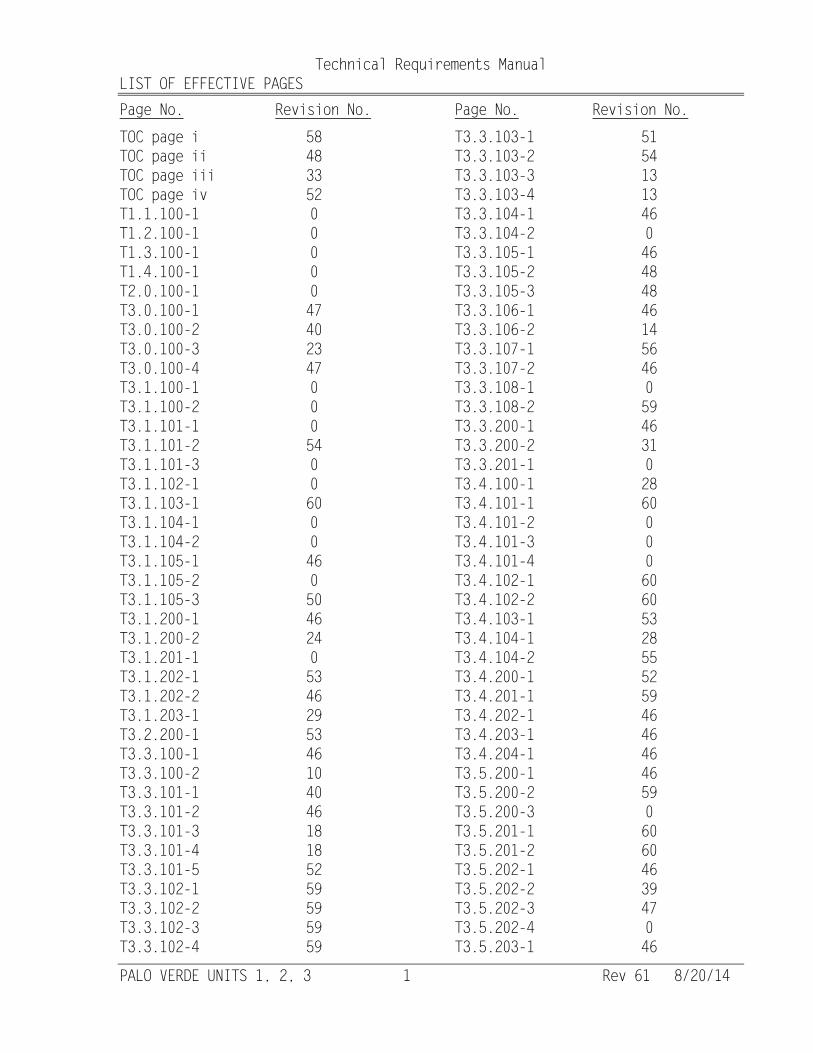
Technical Requirements Manual LIST OF EFFECTIVE PAGES Page No. Revision No. Page No. Revision No.
TOC page i 58 TOC page ii 48 TOC page iii 33 TOC page iv 52 T1.1.100-1 0 T1.2.100-1 0 T1.3.100-1 0 T1.4.100-1 0 T2.0.100-1 0 T3.0.100-1 47 T3.0.100-2 40 T3.0.100-3 23 T3.0.100-4 47 T3.1.100-1 0 T3.1.100-2 0 T3.1.101-1 0 T3.1.101-2 54 T3.1.101-3 0 T3.1.102-1 0 T3.1.103-1 60 T3.1.104-1 0 T3.1.104-2 0 T3.1.105-1 46 T3.1.105-2 0 T3.1.105-3 50 T3.1.200-1 46 T3.1.200-2 24 T3.1.201-1 0 T3.1.202-1 53 T3.1.202-2 46 T3.1.203-1 29 T3.2.200-1 53 T3.3.100-1 46 T3.3.100-2 10 T3.3.101-1 40 T3.3.101-2 46 T3.3.101-3 18 T3.3.101-4 18 T3.3.101-5 52 T3.3.102-1 59 T3.3.102-2 59 T3.3.102-3 59 T3.3.102-4 59
T3.3.103-1 51 T3.3.103-2 54 T3.3.103-3 13 T3.3.103-4 13 T3.3.104-1 46 T3.3.104-2 0 T3.3.105-1 46 T3.3.105-2 48 T3.3.105-3 48 T3.3.106-1 46 T3.3.106-2 14 T3.3.107-1 56 T3.3.107-2 46 T3.3.108-1 0 T3.3.108-2 59 T3.3.200-1 46 T3.3.200-2 31 T3.3.201-1 0 T3.4.100-1 28 T3.4.101-1 60 T3.4.101-2 0 T3.4.101-3 0 T3.4.101-4 0 T3.4.102-1 60 T3.4.102-2 60 T3.4.103-1 53 T3.4.104-1 28 T3.4.104-2 55 T3.4.200-1 52 T3.4.201-1 59 T3.4.202-1 46 T3.4.203-1 46 T3.4.204-1 46 T3.5.200-1 46 T3.5.200-2 59 T3.5.200-3 0 T3.5.201-1 60 T3.5.201-2 60 T3.5.202-1 46 T3.5.202-2 39 T3.5.202-3 47 T3.5.202-4 0 T3.5.203-1 46
Technical Requirements Manual
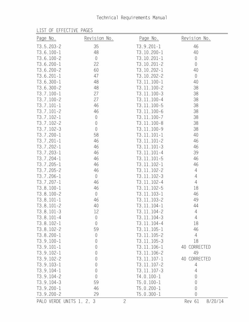
LIST OF EFFECTIVE PAGES Page No. Revision No. Page No. Revision No.
PALO VERDE UNITS 1, 2, 3 2 Rev 61 8/20/14
T3.5.203-2 35 T3.6.100-1 48 T3.6.100-2 0 T3.6.200-1 22 T3.6.200-2 60 T3.6.201-1 47 T3.6.300-1 48 T3.6.300-2 48 T3.7.100-1 27 T3.7.100-2 27 T3.7.101-1 46 T3.7.101-2 46 T3.7.102-1 0 T3.7.102-2 0 T3.7.102-3 0 T3.7.200-1 58 T3.7.201-1 46 T3.7.202-1 46 T3.7.203-1 46 T3.7.204-1 46 T3.7.205-1 46 T3.7.205-2 46 T3.7.206-1 0 T3.7.207-1 46 T3.8.100-1 46 T3.8.100-2 0 T3.8.101-1 46 T3.8.101-2 40 T3.8.101-3 12 T3.8.101-4 0 T3.8.102-1 0 T3.8.102-2 59 T3.8.200-1 0 T3.9.100-1 0 T3.9.101-1 0 T3.9.102-1 0 T3.9.102-2 0 T3.9.103-1 0 T3.9.104-1 0 T3.9.104-2 0 T3.9.104-3 59 T3.9.200-1 46 T3.9.200-2 29
T3.9.201-1 46 T3.10.200-1 40 T3.10.201-1 0 T3.10.201-2 0 T3.10.202-1 40 T3.10.202-2 0 T3.11.100-1 40 T3.11.100-2 38 T3.11.100-3 38 T3.11.100-4 38 T3.11.100-5 38 T3.11.100-6 38 T3.11.100-7 38 T3.11.100-8 38 T3.11.100-9 38 T3.11.101-1 40 T3.11.101-2 46 T3.11.101-3 46 T3.11.101-4 39 T3.11.101-5 46 T3.11.102-1 46 T3.11.102-2 4 T3.11.102-3 4 T3.11.102-4 4 T3.11.102-5 18 T3.11.103-1 46 T3.11.103-2 49 T3.11.104-1 44 T3.11.104-2 4 T3.11.104-3 4 T3.11.104-4 18 T3.11.105-1 46 T3.11.105-2 4 T3.11.105-3 18 T3.11.106-1 40 CORRECTED T3.11.106-2 49 T3.11.107-1 40 CORRECTED T3.11.107-2 4 T3.11.107-3 4 T4.0.100-1 0 T5.0.100-1 0 T5.0.200-1 0 T5.0.300-1 0
Technical Requirements Manual
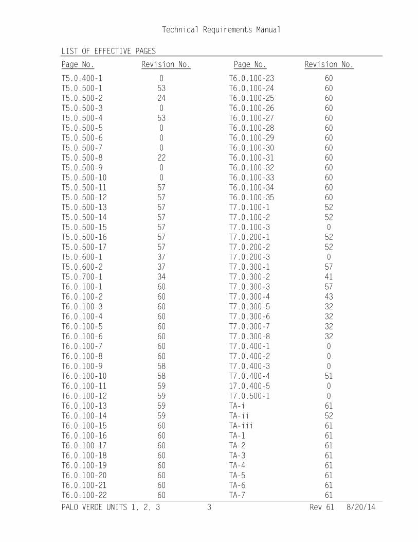
LIST OF EFFECTIVE PAGES Page No. Revision No. Page No. Revision No.
PALO VERDE UNITS 1, 2, 3 3 Rev 61 8/20/14
T5.0.400-1 0 T5.0.500-1 53 T5.0.500-2 24 T5.0.500-3 0 T5.0.500-4 53 T5.0.500-5 0 T5.0.500-6 0 T5.0.500-7 0 T5.0.500-8 22 T5.0.500-9 0 T5.0.500-10 0 T5.0.500-11 57 T5.0.500-12 57 T5.0.500-13 57 T5.0.500-14 57 T5.0.500-15 57 T5.0.500-16 57 T5.0.500-17 57 T5.0.600-1 37 T5.0.600-2 37 T5.0.700-1 34 T6.0.100-1 60 T6.0.100-2 60 T6.0.100-3 60 T6.0.100-4 60 T6.0.100-5 60 T6.0.100-6 60 T6.0.100-7 60 T6.0.100-8 60 T6.0.100-9 58 T6.0.100-10 58 T6.0.100-11 59 T6.0.100-12 59 T6.0.100-13 59 T6.0.100-14 59 T6.0.100-15 60 T6.0.100-16 60 T6.0.100-17 60 T6.0.100-18 60 T6.0.100-19 60 T6.0.100-20 60 T6.0.100-21 60 T6.0.100-22 60
T6.0.100-23 60 T6.0.100-24 60 T6.0.100-25 60 T6.0.100-26 60 T6.0.100-27 60 T6.0.100-28 60 T6.0.100-29 60 T6.0.100-30 60 T6.0.100-31 60 T6.0.100-32 60 T6.0.100-33 60 T6.0.100-34 60 T6.0.100-35 60 T7.0.100-1 52 T7.0.100-2 52 T7.0.100-3 0 T7.0.200-1 52 T7.0.200-2 52 T7.0.200-3 0 T7.0.300-1 57 T7.0.300-2 41 T7.0.300-3 57 T7.0.300-4 43 T7.0.300-5 32 T7.0.300-6 32 T7.0.300-7 32 T7.0.300-8 32 T7.0.400-1 0 T7.0.400-2 0 T7.0.400-3 0 T7.0.400-4 51 17.0.400-5 0 T7.0.500-1 0 TA-i 61 TA-ii 52 TA-iii 61 TA-1 61 TA-2 61 TA-3 61 TA-4 61 TA-5 61 TA-6 61 TA-7 61
Technical Requirements Manual
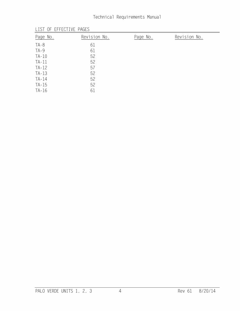
LIST OF EFFECTIVE PAGES Page No. Revision No. Page No. Revision No.
PALO VERDE UNITS 1, 2, 3 4 Rev 61 8/20/14
TA-8 61 TA-9 61 TA-10 52 TA-11 52 TA-12 57 TA-13 52 TA-14 52 TA-15 52 TA-16 61
Palo Verde Units 1, 2, 3 TA-i Rev 61 08/20/14
Technical Requirements Manual
APPENDIX TA
REACTOR COOLANT SYSTEM PRESSURE AND TEMPERATURE LIMITS REPORT
(PTLR)
Palo Verde Nuclear Generating Station Units 1, 2, and 3
Summary of PTLR: This reactor coolant system pressure and temperature limits report (PTLR) has been prepared in accordance with the reporting requirements of Technical Specification 5.6.9. NRC letter dated March 16, 2001, accepted report CE NPSD-683-A, Rev. 6, which provides the methodology for developing this PTLR. Application of CE NPSD-683 to PVNGS is documented in report WCAP-16835, Rev. 1.
TRM Appendix TA PTLR
__________________________________________________________________________
Palo Verde Units 1, 2, 3 TA-iii Rev 61 08/20/14
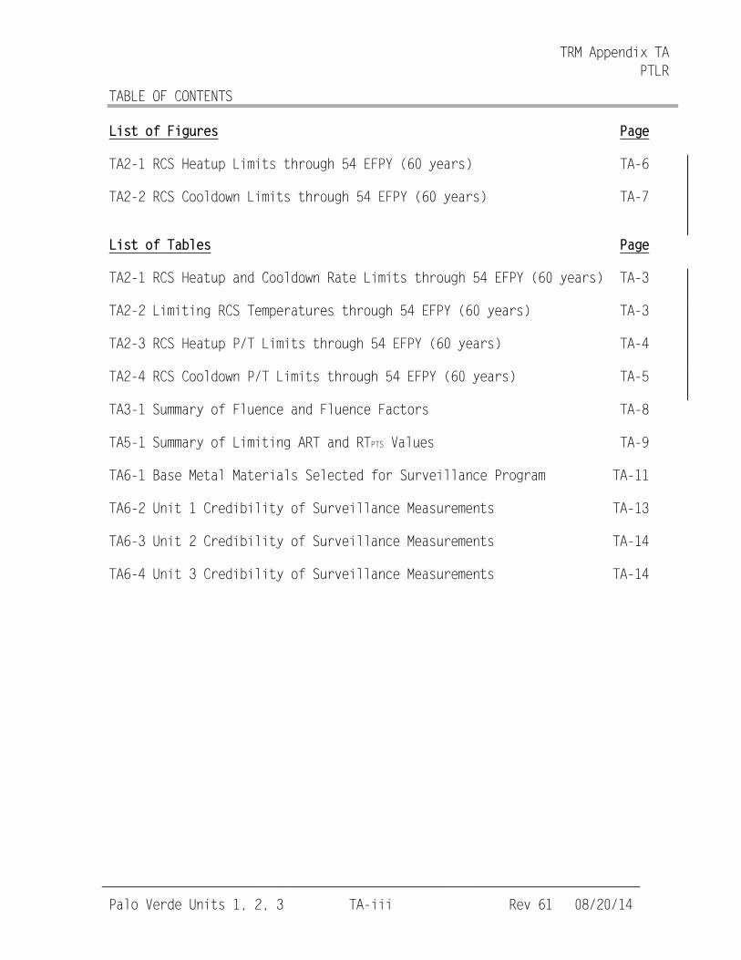
TABLE OF CONTENTS
List of Figures Page
TA2-1 RCS Heatup Limits through 54 EFPY (60 years) TA-6
TA2-2 RCS Cooldown Limits through 54 EFPY (60 years) TA-7
List of Tables Page
TA2-1 RCS Heatup and Cooldown Rate Limits through 54 EFPY (60 years) TA-3
TA2-2 Limiting RCS Temperatures through 54 EFPY (60 years) TA-3
TA2-3 RCS Heatup P/T Limits through 54 EFPY (60 years) TA-4
TA2-4 RCS Cooldown P/T Limits through 54 EFPY (60 years) TA-5
TA3-1 Summary of Fluence and Fluence Factors TA-8
TA5-1 Summary of Limiting ART and RTPTS Values TA-9
TA6-1 Base Metal Materials Selected for Surveillance Program TA-11
TA6-2 Unit 1 Credibility of Surveillance Measurements TA-13
TA6-3 Unit 2 Credibility of Surveillance Measurements TA-14
TA6-4 Unit 3 Credibility of Surveillance Measurements TA-14
TRM Appendix TA PTLR
___________________________________________________________________________ (continued)
Palo Verde Units 1, 2, 3 TA-1 Rev 61 08/20/14
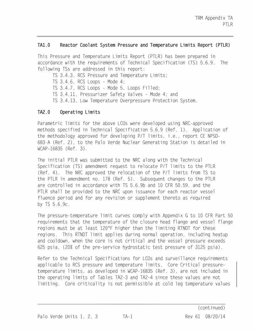
TA1.0 Reactor Coolant System Pressure and Temperature Limits Report (PTLR)
This Pressure and Temperature Limits Report (PTLR) has been prepared in accordance with the requirements of Technical Specification (TS) 5.6.9. The following TSs are addressed in this report: TS 3.4.3, RCS Pressure and Temperature Limits; TS 3.4.6, RCS Loops – Mode 4; TS 3.4.7, RCS Loops – Mode 5, Loops Filled; TS 3.4.11, Pressurizer Safety Valves – Mode 4; and TS 3.4.13, Low Temperature Overpressure Protection System.
TA2.0 Operating Limits
Parametric limits for the above LCOs were developed using NRC-approved methods specified in Technical Specification 5.6.9 (Ref. 1). Application of the methodology approved for developing P/T limits, i.e., report CE NPSD-683-A (Ref. 2), to the Palo Verde Nuclear Generating Station is detailed in WCAP-16835 (Ref. 3).
The initial PTLR was submitted to the NRC along with the Technical Specification (TS) amendment request to relocate P/T limits to the PTLR (Ref. 4). The NRC approved the relocation of the P/T limits from TS to the PTLR in amendment no. 178 (Ref. 5). Subsequent changes to the PTLR are controlled in accordance with TS 5.6.9b and 10 CFR 50.59, and the PTLR shall be provided to the NRC upon issuance for each reactor vessel fluence period and for any revision or supplement thereto as required by TS 5.6.9c.
The pressure-temperature limit curves comply with Appendix G to 10 CFR Part 50 requirements that the temperature of the closure head flange and vessel flange regions must be at least 120°F higher than the limiting RTNDT for these regions. This RTNDT limit applies during normal operation, including heatup and cooldown, when the core is not critical and the vessel pressure exceeds 625 psia, (20% of the pre-service hydrostatic test pressure of 3125 psia).
Refer to the Technical Specifications for LCOs and surveillance requirements applicable to RCS pressure and temperature limits. Core Critical pressure-temperature limits, as developed in WCAP-16835 (Ref. 3), are not included in the operating limits of Tables TA2-3 and TA2-4 since these values are not limiting. Core criticality is not permissible at cold leg temperature values
TRM Appendix TA PTLR
___________________________________________________________________________ (continued)
Palo Verde Units 1, 2, 3 TA-2 Rev 61 08/20/14
_______________________________________________________________________________
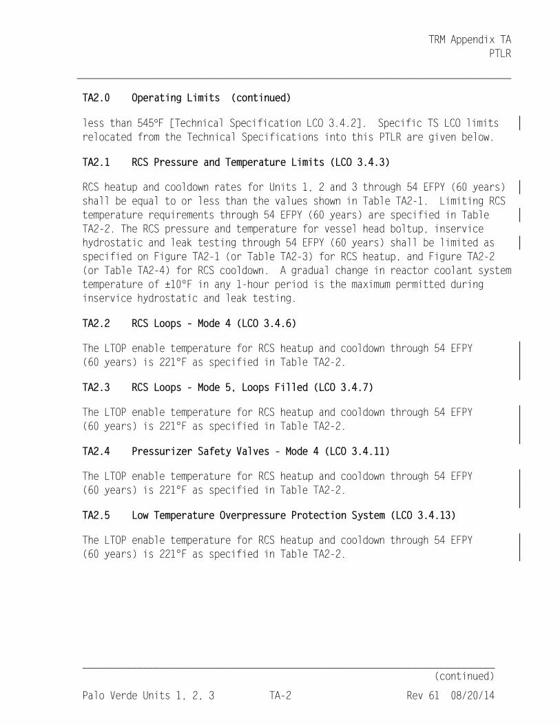
TA2.0 Operating Limits (continued)
less than 545°F [Technical Specification LCO 3.4.2]. Specific TS LCO limits relocated from the Technical Specifications into this PTLR are given below.
TA2.1 RCS Pressure and Temperature Limits (LCO 3.4.3)
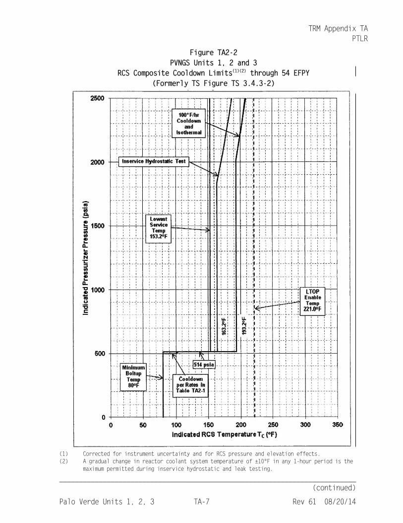
RCS heatup and cooldown rates for Units 1, 2 and 3 through 54 EFPY (60 years) shall be equal to or less than the values shown in Table TA2-1. Limiting RCS temperature requirements through 54 EFPY (60 years) are specified in Table TA2-2. The RCS pressure and temperature for vessel head boltup, inservice hydrostatic and leak testing through 54 EFPY (60 years) shall be limited as specified on Figure TA2-1 (or Table TA2-3) for RCS heatup, and Figure TA2-2 (or Table TA2-4) for RCS cooldown. A gradual change in reactor coolant system temperature of ±10ºF in any 1-hour period is the maximum permitted during inservice hydrostatic and leak testing.
TA2.2 RCS Loops – Mode 4 (LCO 3.4.6)
The LTOP enable temperature for RCS heatup and cooldown through 54 EFPY (60 years) is 221°F as specified in Table TA2-2.
TA2.3 RCS Loops – Mode 5, Loops Filled (LCO 3.4.7)
The LTOP enable temperature for RCS heatup and cooldown through 54 EFPY (60 years) is 221°F as specified in Table TA2-2.
TA2.4 Pressurizer Safety Valves – Mode 4 (LCO 3.4.11)
The LTOP enable temperature for RCS heatup and cooldown through 54 EFPY (60 years) is 221°F as specified in Table TA2-2.
TA2.5 Low Temperature Overpressure Protection System (LCO 3.4.13)
The LTOP enable temperature for RCS heatup and cooldown through 54 EFPY (60 years) is 221°F as specified in Table TA2-2.
TRM Appendix TA PTLR
___________________________________________________________________________ (continued)
Palo Verde Units 1, 2, 3 TA-3 Rev 61 08/20/14
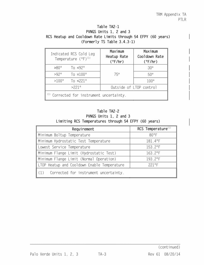
Table TA2-1 PVNGS Units 1, 2 and 3
RCS Heatup and Cooldown Rate Limits through 54 EFPY (60 years) (Formerly TS Table 3.4.3-1)
Indicated RCS Cold Leg Temperature (ºF)(1)
Maximum Heatup Rate (ºF/hr)
Maximum Cooldown Rate
(ºF/hr) ≥80º To ≤92º
75° 30°
>92º To ≤100º 50° >100º To ≤221º 100°
>221º Outside of LTOP control (1) Corrected for instrument uncertainty.
Table TA2-2 PVNGS Units 1, 2 and 3
Limiting RCS Temperatures through 54 EFPY (60 years)
Requirement RCS Temperature(1) Minimum Boltup Temperature 80°F Minimum Hydrostatic Test Temperature 181.4°F Lowest Service Temperature 153.2°F Minimum Flange Limit (Hydrostatic Test) 163.2°F Minimum Flange Limit (Normal Operation) 193.2°F LTOP Heatup and Cooldown Enable Temperature 221°F
(1) Corrected for instrument uncertainty.
TRM Appendix TA PTLR
___________________________________________________________________________ (continued)
Palo Verde Units 1, 2, 3 TA-4 Rev 61 08/20/14
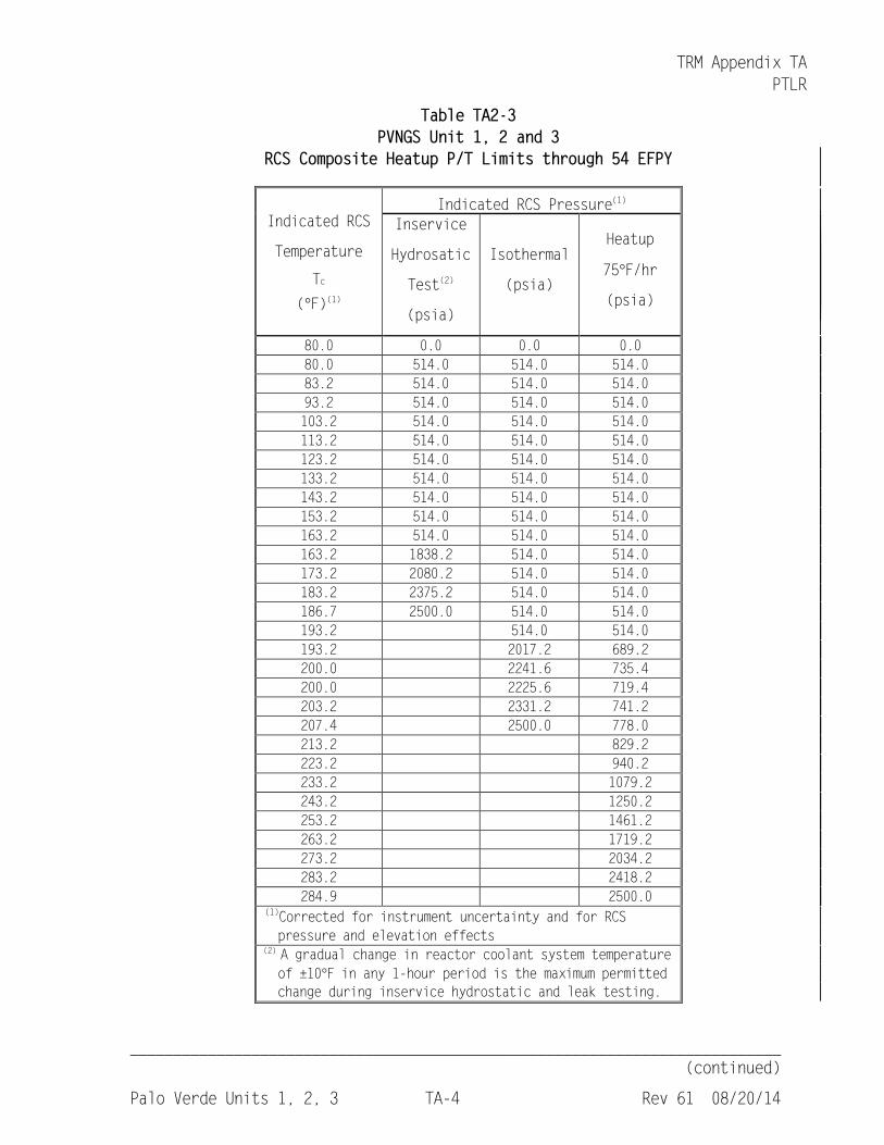
Table TA2-3 PVNGS Unit 1, 2 and 3
RCS Composite Heatup P/T Limits through 54 EFPY
Indicated RCS
Temperature
Tc (°F)(1)
Indicated RCS Pressure(1) Inservice
Hydrosatic
Test(2)
(psia)
Isothermal
(psia)
Heatup
75°F/hr
(psia)
80.0 0.0 0.0 0.0 80.0 514.0 514.0 514.0 83.2 514.0 514.0 514.0 93.2 514.0 514.0 514.0 103.2 514.0 514.0 514.0 113.2 514.0 514.0 514.0 123.2 514.0 514.0 514.0 133.2 514.0 514.0 514.0 143.2 514.0 514.0 514.0 153.2 514.0 514.0 514.0 163.2 514.0 514.0 514.0 163.2 1838.2 514.0 514.0 173.2 2080.2 514.0 514.0 183.2 2375.2 514.0 514.0 186.7 2500.0 514.0 514.0 193.2 514.0 514.0 193.2 2017.2 689.2 200.0 2241.6 735.4 200.0 2225.6 719.4 203.2 2331.2 741.2 207.4 2500.0 778.0 213.2 829.2 223.2 940.2 233.2 1079.2 243.2 1250.2 253.2 1461.2 263.2 1719.2 273.2 2034.2 283.2 2418.2 284.9 2500.0
(1)Corrected for instrument uncertainty and for RCS pressure and elevation effects
(2) A gradual change in reactor coolant system temperature of ±10°F in any 1-hour period is the maximum permitted change during inservice hydrostatic and leak testing.
TRM Appendix TA PTLR
___________________________________________________________________________ (continued)
Palo Verde Units 1, 2, 3 TA-5 Rev 61 08/20/14
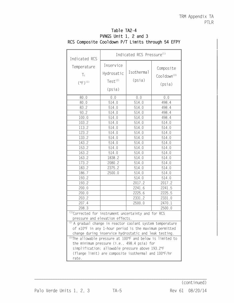
Table TA2-4 PVNGS Unit 1, 2 and 3
RCS Composite Cooldown P/T Limits through 54 EFPY
Indicated RCS
Temperature
Tc
(°F)(1)
Indicated RCS Pressure(1)
Inservice
Hydrosatic
Test(2)
(psia)
Isothermal
(psia)
Composite
Cooldown(3)
(psia)
80.0 0.0 0.0 0.0 80.0 514.0 514.0 498.4 83.2 514.0 514.0 498.4 93.2 514.0 514.0 498.4 100.0 514.0 514.0 498.4 103.2 514.0 514.0 514.0 113.2 514.0 514.0 514.0 123.2 514.0 514.0 514.0 133.2 514.0 514.0 514.0 143.2 514.0 514.0 514.0 153.2 514.0 514.0 514.0 163.2 514.0 514.0 514.0 163.2 1838.2 514.0 514.0 173.2 2080.2 514.0 514.0 183.2 2375.2 514.0 514.0 186.7 2500.0 514.0 514.0 193.2 514.0 514.0 193.2 2017.2 2017.2 200.0 2241.6 2241.5 200.0 2225.6 2225.5 203.2 2331.2 2331.0 207.4 2500.0 2470.1 208.3 2500.0
(1)Corrected for instrument uncertainty and for RCS pressure and elevation effects.
(2) A gradual change in reactor coolant system temperature of ±10°F in any 1-hour period is the maximum permitted change during inservice hydrostatic and leak testing.
(3)The allowable pressure at 100°F and below is limited to the minimum pressure (i.e., 498.4 psia) for simplification; allowable pressure above 193.2°F (flange limit) are composite isothermal and 100°F/hr rate.
TRM Appendix TA PTLR
___________________________________________________________________________ (continued)
Palo Verde Units 1, 2, 3 TA-6 Rev 61 08/20/14
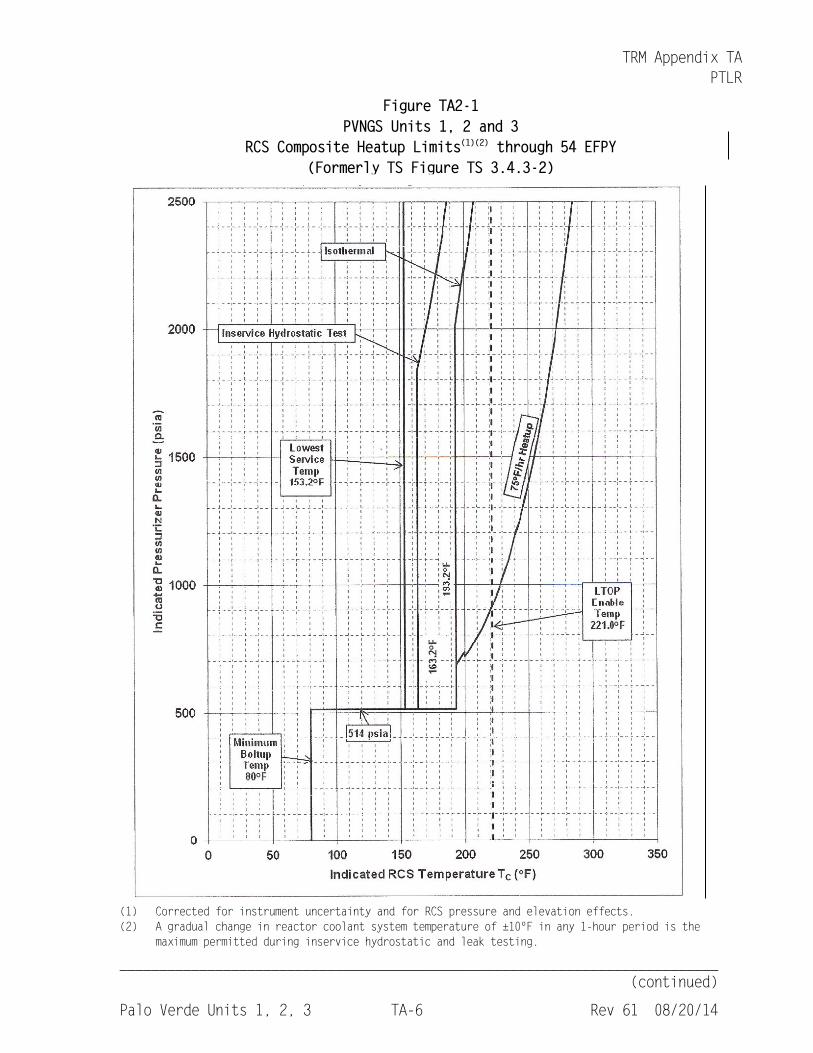
Figure TA2-1 PVNGS Units 1, 2 and 3
RCS Composite Heatup Limits(1)(2) through 54 EFPY (Formerly TS Figure TS 3.4.3-2)
(1) Corrected for instrument uncertainty and for RCS pressure and elevation effects. (2) A gradual change in reactor coolant system temperature of ±10ºF in any 1-hour period is the
maximum permitted during inservice hydrostatic and leak testing.
TRM Appendix TA PTLR
___________________________________________________________________________ (continued)
Palo Verde Units 1, 2, 3 TA-7 Rev 61 08/20/14
Figure TA2-2 PVNGS Units 1, 2 and 3
RCS Composite Cooldown Limits(1)(2) through 54 EFPY (Formerly TS Figure TS 3.4.3-2)
(1) Corrected for instrument uncertainty and for RCS pressure and elevation effects. (2) A gradual change in reactor coolant system temperature of ±10ºF in any 1-hour period is the
maximum permitted during inservice hydrostatic and leak testing.
TRM Appendix TA PTLR
___________________________________________________________________________ (continued)
Palo Verde Units 1, 2, 3 TA-8 Rev 61 08/20/14
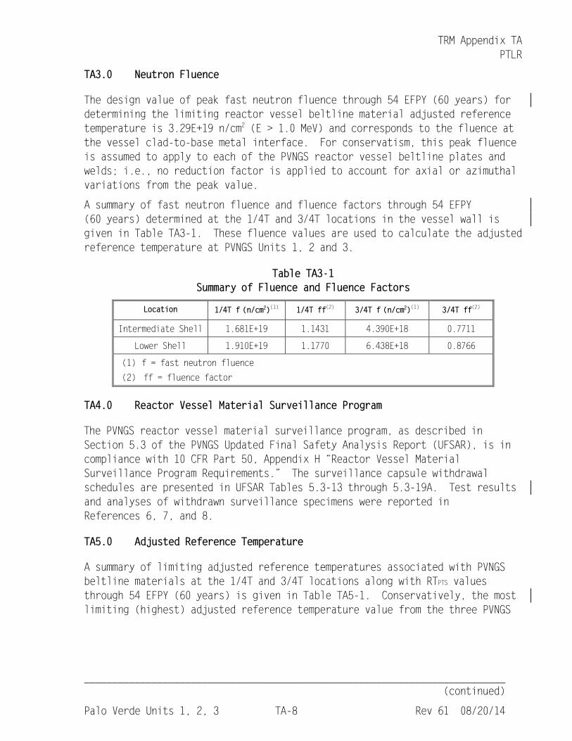
TA3.0 Neutron Fluence
The design value of peak fast neutron fluence through 54 EFPY (60 years) for determining the limiting reactor vessel beltline material adjusted reference temperature is 3.29E+19 n/cm2 (E > 1.0 MeV) and corresponds to the fluence at the vessel clad-to-base metal interface. For conservatism, this peak fluence is assumed to apply to each of the PVNGS reactor vessel beltline plates and welds; i.e., no reduction factor is applied to account for axial or azimuthal variations from the peak value.
A summary of fast neutron fluence and fluence factors through 54 EFPY (60 years) determined at the 1/4T and 3/4T locations in the vessel wall is given in Table TA3-1. These fluence values are used to calculate the adjusted reference temperature at PVNGS Units 1, 2 and 3.
Table TA3-1 Summary of Fluence and Fluence Factors
Location 1/4T f (n/cm2)(1) 1/4T ff(2) 3/4T f (n/cm2)(1) 3/4T ff(2)
Intermediate Shell 1.681E+19 1.1431 4.390E+18 0.7711
Lower Shell 1.910E+19 1.1770 6.438E+18 0.8766
(1) f = fast neutron fluence
(2) ff = fluence factor
TA4.0 Reactor Vessel Material Surveillance Program
The PVNGS reactor vessel material surveillance program, as described in Section 5.3 of the PVNGS Updated Final Safety Analysis Report (UFSAR), is in compliance with 10 CFR Part 50, Appendix H “Reactor Vessel Material Surveillance Program Requirements.” The surveillance capsule withdrawal schedules are presented in UFSAR Tables 5.3-13 through 5.3-19A. Test results and analyses of withdrawn surveillance specimens were reported in References 6, 7, and 8.
TA5.0 Adjusted Reference Temperature
A summary of limiting adjusted reference temperatures associated with PVNGS beltline materials at the 1/4T and 3/4T locations along with RTPTS values through 54 EFPY (60 years) is given in Table TA5-1. Conservatively, the most limiting (highest) adjusted reference temperature value from the three PVNGS
TRM Appendix TA PTLR
__________________________________________________________________________
(continued)
Palo Verde Units 1, 2, 3 TA-9 Rev 61 08/20/14
_______________________________________________________________________________
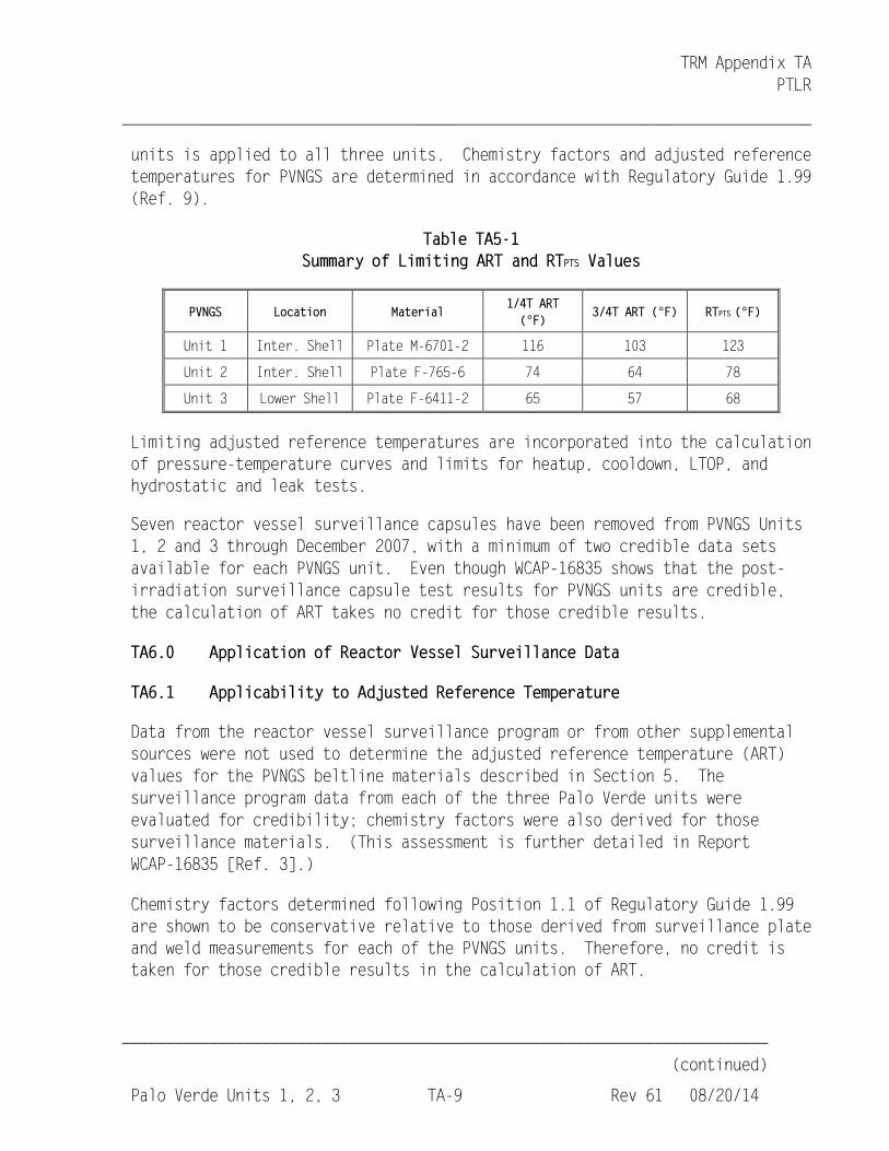
units is applied to all three units. Chemistry factors and adjusted reference temperatures for PVNGS are determined in accordance with Regulatory Guide 1.99 (Ref. 9).
Table TA5-1 Summary of Limiting ART and RTPTS Values
PVNGS Location Material 1/4T ART (°F)
3/4T ART (°F) RTPTS (°F)
Unit 1 Inter. Shell Plate M-6701-2 116 103 123
Unit 2 Inter. Shell Plate F-765-6 74 64 78
Unit 3 Lower Shell Plate F-6411-2 65 57 68
Limiting adjusted reference temperatures are incorporated into the calculation of pressure-temperature curves and limits for heatup, cooldown, LTOP, and hydrostatic and leak tests.
Seven reactor vessel surveillance capsules have been removed from PVNGS Units 1, 2 and 3 through December 2007, with a minimum of two credible data sets available for each PVNGS unit. Even though WCAP-16835 shows that the post-irradiation surveillance capsule test results for PVNGS units are credible, the calculation of ART takes no credit for those credible results.
TA6.0 Application of Reactor Vessel Surveillance Data
TA6.1 Applicability to Adjusted Reference Temperature
Data from the reactor vessel surveillance program or from other supplemental sources were not used to determine the adjusted reference temperature (ART) values for the PVNGS beltline materials described in Section 5. The surveillance program data from each of the three Palo Verde units were evaluated for credibility; chemistry factors were also derived for those surveillance materials. (This assessment is further detailed in Report WCAP-16835 [Ref. 3].)
Chemistry factors determined following Position 1.1 of Regulatory Guide 1.99 are shown to be conservative relative to those derived from surveillance plate and weld measurements for each of the PVNGS units. Therefore, no credit is taken for those credible results in the calculation of ART.
TRM Appendix TA PTLR
__________________________________________________________________________
Palo Verde Units 1, 2, 3 TA-16 Rev 61 08/20/14
_______________________________________________________________________________
Limits and LTOP Requirements from the Technical Specifications,” April 2001.
3. Westinghouse Report WCAP-16835, Revision 1, “Palo Verde Nuclear Generating Station Units 1, 2 and 3, Basis for RCS Pressure-Temperature Limits Report,” March 2012.
4. APS letter No. 102-05960 to NRC, “Request for Technical Specification Amendment to Relocate the Reactor Coolant System Pressure and Temperature Limits and the Low Temperature Overpressure Protection Enable Temperatures,” dated February 19, 2009. Supplemented by APS Letter No. 102-06112, “Response to Request for Additional Information for Technical Specification Amendment and Exemption from 10 CFR 50, Appendix G, to Relocate the Reactor Coolant System Pressure and Temperature Limits and the Low Temperature Overpressure Protection Enable Temperatures,” dated December 22, 2009.
5. Letter, NRC to APS, “Palo Verde Nuclear Generating Station, Units 1, 2, and 3 - Issuance of Amendments Re: [Relocation of RCS Pressure and Temperature Limits] (TAC NOS. ME0698, ME0699, AND ME0700),” dated February 25, 2010 (Amendment No. 178).
6. APS letter no. 102-05242 to NRC, Palo Verde Nuclear Generating Station Unit 1 Reactor Vessel Material Surveillance Capsule at 230°,” April 5, 2005 (transmittal of WCAP-16374-NP, “Analysis of Capsule 230° from Arizona Public Service Company Palo Verde Unit 1 Reactor Vessel Radiation Surveillance Program,” February 2005).
7. APS letter no. 102-05457 to NRC, Palo Verde Nuclear Generating Station Unit 2 Reactor Vessel Material Surveillance Capsule at 230°,” April 4, 2006 (transmittal of WCAP-16524-NP, “Analysis of Capsule 230° from Arizona Public Service Company Palo Verde Unit 2 Reactor Vessel Radiation Surveillance Program,” February 2006).
8. APS letter no. 102-05348 to NRC, Palo Verde Nuclear Generating Station Unit 3 Analysis of Reactor Vessel Material Surveillance Capsule at 230°,” September 26, 2005 (transmittal of WCAP-16449-NP, “Analysis of Capsule 230° from Arizona Public Service Company Palo Verde Unit 3 Reactor Vessel Radiation Surveillance Program,” August 2005).
9. Regulatory Guide 1.99, Revision 2, “Radiation Embrittlement of Reactor Vessel Materials,” U.S. Nuclear Regulatory Commission, May 1998.