Embed Size (px)
Citation preview
TRM Thermal Risk Management PCB Simulation Software
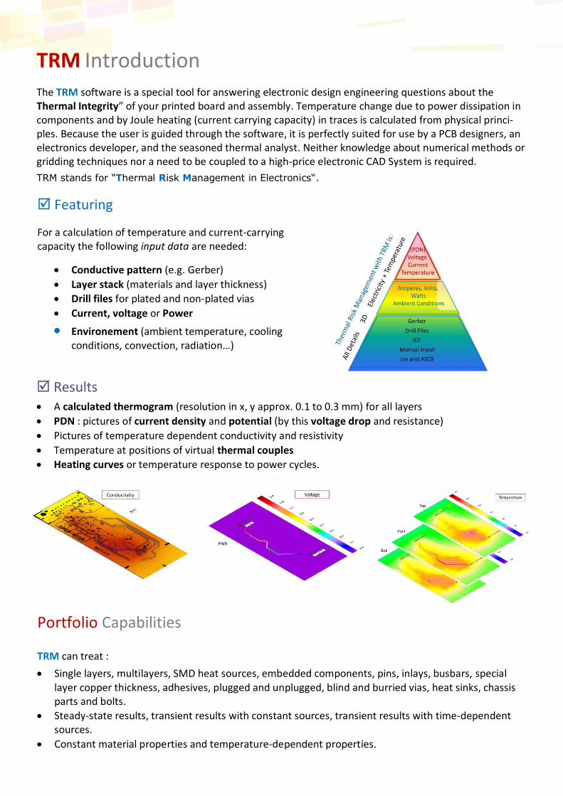
Results • A calculated thermogram (resolution in x, y approx. 0.1 to 0.3 mm) for all layers
• PDN : pictures of current density and potential (by this voltage drop and resistance)
• Pictures of temperature dependent conductivity and resistivity
• Temperature at positions of virtual thermal couples
• Heating curves or temperature response to power cycles.
TRM Introduction
The TRM software is a special tool for answering electronic design engineering questions about the Thermal Integrity” of your printed board and assembly. Temperature change due to power dissipation in components and by Joule heating (current carrying capacity) in traces is calculated from physical princi-ples. Because the user is guided through the software, it is perfectly suited for use by a PCB designers, an electronics developer, and the seasoned thermal analyst. Neither knowledge about numerical methods or gridding techniques nor a need to be coupled to a high-price electronic CAD System is required.
TRM stands for “Thermal Risk Management in Electronics“.
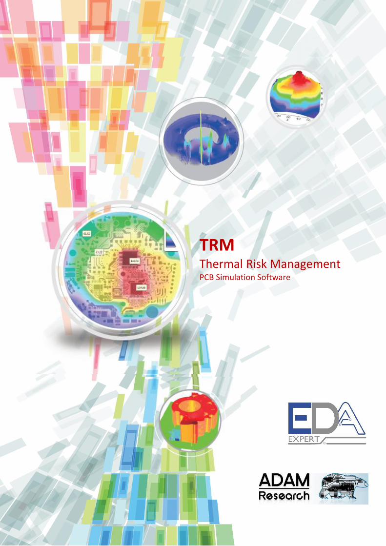
Featuring
For a calculation of temperature and current-carrying capacity the following input data are needed:
• Conductive pattern (e.g. Gerber)
• Layer stack (materials and layer thickness)
• Drill files for plated and non-plated vias
• Current, voltage or Power
• Environement (ambient temperature, cooling conditions, convection, radiation…)
Portfolio Capabilities TRM can treat :
• Single layers, multilayers, SMD heat sources, embedded components, pins, inlays, busbars, special layer copper thickness, adhesives, plugged and unplugged, blind and burried vias, heat sinks, chassis parts and bolts.
• Steady-state results, transient results with constant sources, transient results with time-dependent sources.
• Constant material properties and temperature-dependent properties.
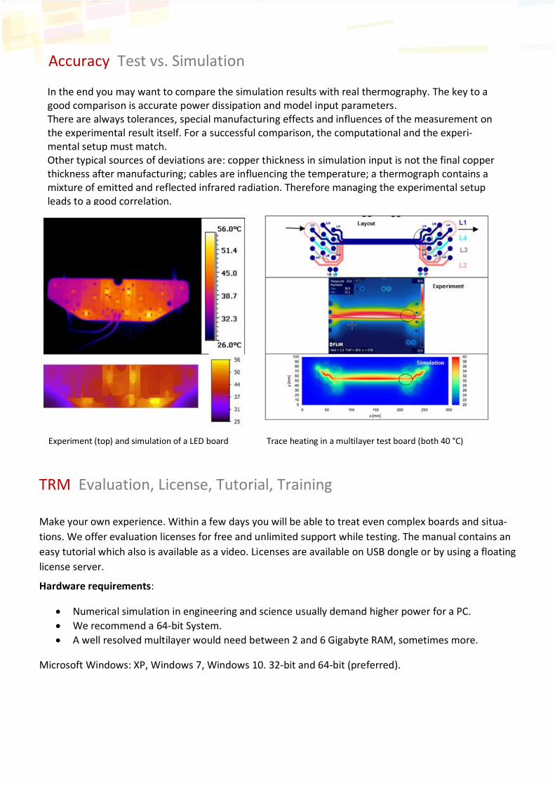
In the end you may want to compare the simulation results with real thermography. The key to a good comparison is accurate power dissipation and model input parameters. There are always tolerances, special manufacturing effects and influences of the measurement on the experimental result itself. For a successful comparison, the computational and the experi-mental setup must match. Other typical sources of deviations are: copper thickness in simulation input is not the final copper thickness after manufacturing; cables are influencing the temperature; a thermograph contains a mixture of emitted and reflected infrared radiation. Therefore managing the experimental setup leads to a good correlation.
TRM Evaluation, License, Tutorial, Training
Accuracy Test vs. Simulation
Experiment (top) and simulation of a LED board Trace heating in a multilayer test board (both 40 °C)
Make your own experience. Within a few days you will be able to treat even complex boards and situa-
tions. We offer evaluation licenses for free and unlimited support while testing. The manual contains an
easy tutorial which also is available as a video. Licenses are available on USB dongle or by using a floating
license server.
Hardware requirements:
• Numerical simulation in engineering and science usually demand higher power for a PC.
• We recommend a 64-bit System.
• A well resolved multilayer would need between 2 and 6 Gigabyte RAM, sometimes more.
Microsoft Windows: XP, Windows 7, Windows 10. 32-bit and 64-bit (preferred).
Thermal Risk Management PCB Thermal Simulation Software
www.adam-research.com
11-13 Avenue de la division Leclerc, 94230, Cachan, FRANCE
Tel : +33 (0) 1 49 84 86 26
www.eda-expert.com