Embed Size (px)
Citation preview

Bulletin 47019-G
PVG Open Loop Pumps
OILG_1529_Bulletin_47019-G2.qxd 9/13/05 12:30 PM Page 2

Table of Contents
Performance Assurance page 3
Features and Benefits 4-5
Specifications 6
Shaft Torque Ratings 7
Pressure Pick-ups 7
Controls 8-9
Performance Curves
Efficiency Delivery, Horsepower, Etc. 10-11
Sound 11-12
Inlet Suction/Supercharge 13-14
Ordering Information 15
Copyright 2005 ■ The Oilgear Company ■ All Rights Reserved
Tabl
e of
Con
tent
s
2
OILG_1529_Bulletin_47019-G2.qxd 9/13/05 12:30 PM Page 3

Every Oilgear product is shipped
to you with our Performance Assurance —
a corporate commitment to stay with your
installation until our equipment performs
as specified.
Hydraulic equipment and systems have been
Oilgear’s primary business since 1921. For
decades, we have developed hydraulic techniques
to meet the unique needs and unusual fluid power
problems of machinery builders and users
worldwide, matching fluid power systems to a
tremendous range of applications and industries.
Our exclusive Performance Assurance program is
built upon that strong foundation.
PERFORMANCE ASSURANCE –STANDARD WITH EVERY OILGEAR COMPONENT
As a customer, you also benefit from access to
Oilgear’s impressive technical support network.
You’ll find factory trained and field-experienced
application engineers on staff at every Oilgear
facility. They are backed by headquarters staff
who can access the records and knowledge learned
from decades of solving the most difficult
hydraulic challenges.
When your design or purchase is complete, our
service is just beginning. If you ever need us, our
Oilgear engineers will be there, ready to help you
with the education, field service, parts and repairs
to assure that your installation runs smoothly —
and keeps right on running.
Performance Assurance
3
OILG_1529_Bulletin_47019-G2.qxd 9/13/05 12:30 PM Page 4

Computer optimized, high pressurehigh volume pump, with Oilgear’stime proven rotating group.
■ Provides double the horsepower in the same package.
■ Provides reduced shifting time for high response systems.
Four-way pilot operated control.■ Provides fast on and off stroke time.■ Maintains constant pressure over
full volume range.■ Delivers high performance in a
compact package.
SAE Heavy duty shaft.■ Allows high thru torque capability.■ Dual units can handle full pressure
and volume.
SAE keyed or SAE splined shaft.
Sealed front shaft bearings.■ Enables operation with low viscosity
or other special fluids.
Swashblock with polymerous bearings.■ Allows running on low viscosity or
other special fluids.■ Permits constant control reaction with
low hysteresis.■ Eliminates troublesome yoke bearings■ Provides long life.
Patented pressure lubricated swashblock.■ Delivers high performance for high
pressure high cycle operation.■ Pressure lubricated upper and lower
saddle bearings provides for long life.
Hardened steel shoes with specially designedface for increased fluid retention, running onhardened swashblock surface.
■ Provides a higher degree of contaminate resistance.
■ Allows higher pressure operation.■ Enables operation with low viscosity
or other special fluids.■ Provides long life.
PVG Open Loop Pumps Large control selection.■ Pressure and volume controls are
available with a large variety of options.
■ Field interchangeability without disconnecting from drive or system piping.
Rugged cylinder design■ Hardened nodular iron
construction for improved performance and contamination resistance.
Feat
ures
and
Ben
efits
7
6
2
1
3
4
5
13
8
4
OILG_1529_Bulletin_47019-G2.qxd 9/13/05 12:30 PM Page 5

Hardened cylinder surface running onhardened valve plate “hard-on-hard”.
■ Provides greater resistance to contamination.
■ Provides long life.■ Allows operation with low
viscosity or other special fluids.
Valve plate selection.■ Rear or top and bottom port
connections available.
Thru-shaft availability.■ Allows for multiple pump installation
from a single drive shaft.■ Dual configuration with capability
of full load on both pumps.■ Has provisions for mounting “AA”
thru “C” sizes for rear pumps.
Cylinder mounted polymerous journal bearings.■ Allows operaton with low viscosity or
other special fluids.■ Provides infinite bearing life.■ Enables compact design.
Quiet valve plate design.■ Minimizes noise at typical
electric motor speeds.■ Nodular iron construction
for long life.
Features and Benefits
14
12
11
10
9
5
OILG_1529_Bulletin_47019-G2.qxd 9/13/05 12:31 PM Page 6

Spec
ifica
tions
SPECIFICATIONS
Nominal Performance Specifications
FLOW RATEat 1800 rpm, rated POWER INLET
THEORETICAL RATED cont. pressure & at rated cont.UNIT MAXIMUM CONTINUOUS MAXIMUM 14.7 psia (bar abs) MAXIMUM pressure &SIZE DISPLACEMENT PRESSURE PRESSURE inlet conditions SPEED 1800 rpm
in3/rev. ml/rev. psi bar psi bar gpm l/min rpm hp kw
048 2.93 48,0 5000 344,8 5800 400,0 21.1 79,9 2700 73 54,5
065 3.98 65,0 5000 344,8 5800 400,0 28.8 108,9 2700 100 74,6
075 4.60 75,4 3750 258,6 4250 293,1 33.3 126,0 2700 89 66,4
100 6.00 98,3 5000 344,8 5800 400,0 42.4 160,5 2400 150 111,9
130 7.94 130,2 3750 258,6 4250 293,1 57.6 218,0 2400 150 111,9
Case pressure should be less than 25 psi (1,7 bar). For higher pressure, consult factory. Thru Torque = 5,252 in. lbs.† Higher speeds available – consult factory.
Nominal Dimensions
LENGTH WIDTH HEIGHT WEIGHT
UNIT SIZE in. mm. in. mm. in. mm. lbs. kg. FACE MOUNTING
048, 065 & 075 12.0 303,9 6.9 174,5 6.3 160,4 68 31 SAE “B” 2 & 4 Bolt
100 & 130 13.0 330,5 8.4 212,9 7.3 185,7 110 50 SAE “C” 2 Bolt
All dimensions (without controls) are approximate. For detailed dimensions, contact your Oilgear Representative.
6
OILG_1529_Bulletin_47019-G2.qxd 9/13/05 12:31 PM Page 7
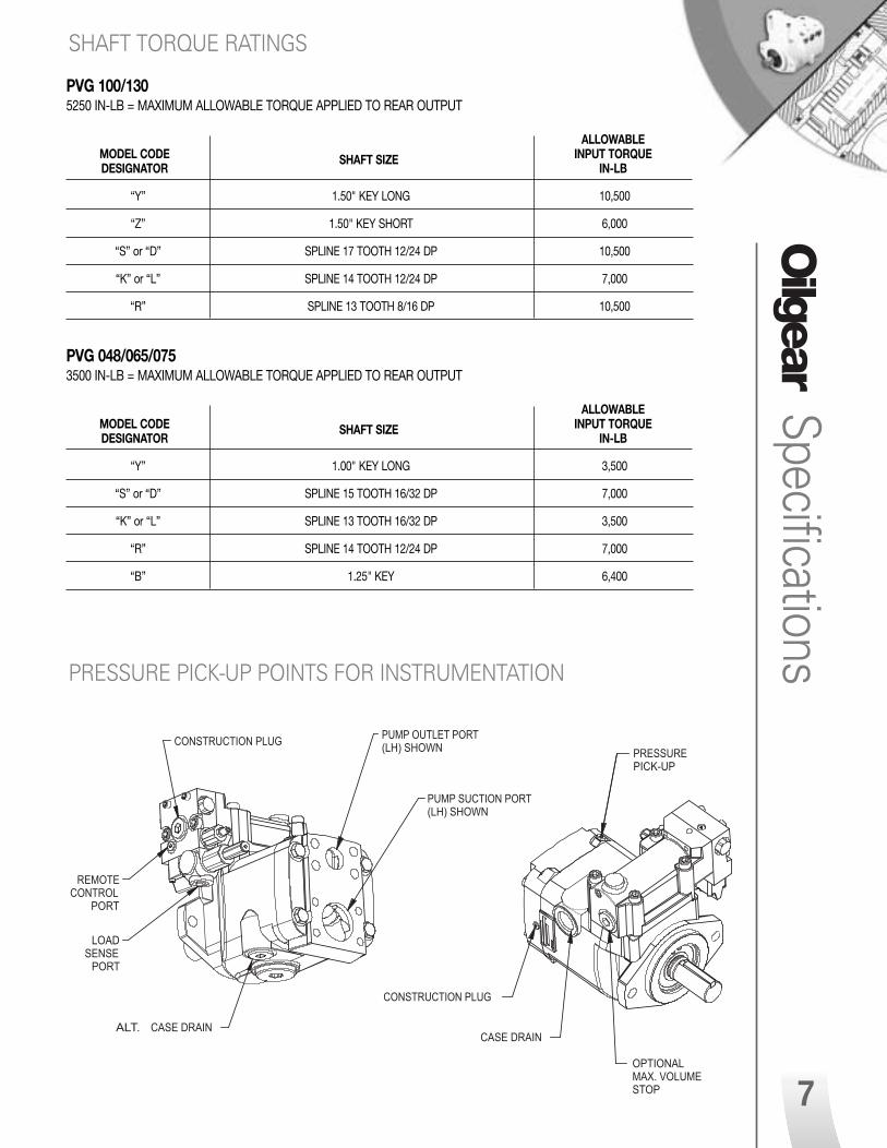
PVG 100/1305250 IN-LB = MAXIMUM ALLOWABLE TORQUE APPLIED TO REAR OUTPUT
ALLOWABLEMODEL CODE SHAFT SIZE INPUT TORQUEDESIGNATOR IN-LB
“Y” 1.50" KEY LONG 10,500
“Z” 1.50" KEY SHORT 6,000
“S” or “D” SPLINE 17 TOOTH 12/24 DP 10,500
“K” or “L” SPLINE 14 TOOTH 12/24 DP 7,000
“R” SPLINE 13 TOOTH 8/16 DP 10,500
PVG 048/065/0753500 IN-LB = MAXIMUM ALLOWABLE TORQUE APPLIED TO REAR OUTPUT
ALLOWABLEMODEL CODE SHAFT SIZE INPUT TORQUEDESIGNATOR IN-LB
“Y” 1.00" KEY LONG 3,500
“S” or “D” SPLINE 15 TOOTH 16/32 DP 7,000
“K” or “L” SPLINE 13 TOOTH 16/32 DP 3,500
“R” SPLINE 14 TOOTH 12/24 DP 7,000
“B” 1.25" KEY 6,400
SHAFT TORQUE RATINGS
PRESSURE PICK-UP POINTS FOR INSTRUMENTATION
Specifications
7
ALT. CASE DRAIN
LOADSENSE
PORT
PUMP OUTLET PORT(LH) SHOWN
PUMP SUCTION PORT(LH) SHOWN
CONSTRUCTION PLUG
REMOTECONTROL
PORT
CASE DRAIN
PRESSUREPICK-UP
CONSTRUCTION PLUG
OPTIONALMAX. VOLUMESTOP
OILG_1529_Bulletin_47019-G2.qxd 9/13/05 12:31 PM Page 8

Pressure Compensator Ensures maximum pump flow untilunit reaches preset control pressuresetting then regulates output flowto match the requirements of thesystem while maintaining presetoutput pressure.
Can be adjusted from 200 psiworking pressure up to themaximum pressure rating of pump.
FL
OW
PRESSURERelated PumpPressure
A
1B
GPA
OP1 OP2
OP6
OP3 OP4
RP1
1A
OP14
FL
OW
PRESSURE
A RP1
1B
GPA
N F
PUMP
STROKE
OP1
OP2
OP6OP12
OP3 OP4
1A
OP14
OP13
LSOP9
A
1B
GPA
OP1 OP2
OP6
OP3 OP4
OP8RP1
1A
OP14
FL
OW
PRESSURE
P1 P2
A
1B
GPA
OP1OP2
OP6
OP3 OP4
OP8RP1
OP10
1A
OP14
Pum
p Co
ntro
lsPump Controls**PRESSURE*
VOLUME/PRESSURE SENSING*
ELECTRONIC*
Horsepower Limiter Automatically reduces delivery, as unit pressurerises, to limit horsepower consumption.
Dual Pressure CompensatorProvides two independently adjustable pressurecompensated settings as selected by an integral solenoid.
Electronic Proportional Pressure CompensatorProvides an infinite number of independent remotely adjustable pressure settings in response to an electrical command.
Load SensingA constant flow output is maintained for a given flowcontrol valve setting regardless of changes in drivespeed and/or working pressure.
OP11
DR
25MICRON
A
1B
GPA
OP1 OP2
OP6
OP3 OP4
OP8RP1
1A
OP14
FL
OW
PRESSURE
P4 P P3P2P1
Electronic Servo Valve An electrohydraulic servo valve positions the swashplate mechanism with a closed-loop position control (with LVDT feedback) providinga highly accurate remote variable delivery control.
“P-1”
“P/H”
“P/A”“P/B”
“V-M”“V-S”
“P/F”
“P-2”
8
OILG_1529_Bulletin_47019-G2.qxd 9/13/05 12:31 PM Page 9

FL
OW
PRESSURE
SOLENOIDOFF
SOLENOIDON
LS
OP8A RP1
1B
GPA
N F
PUMP
STROKE
OP1
OP2
OP6OP12
OP3 OP4
OP9
1A
OP13
OP14
VOLUME*
Pump Controls
A
B
GPA
1
1A
A
1B
GPA
OP1 OP2
OP6
OP3 OP4
OP8RP1
1A
DR
OP14
Soft Start Pressure CompensatorPump starts “softly” by going quickly at low pressureto a reduced flow setting, thereby reducing start uptorque requirements.
Fixed VolumeFixed displacement units available with strokesetting of three quarters and full volume.
Horsepower Limiter with Load SensingLoad sensing control matches flow and pressure to loaddemand until (limited) horsepower setting is reached.Control then automatically reduces delivery as systempressure rises.
* Be sure system and pumps are protected with a high pressure relief valve against overloads.
** For detailed circuits of a particular size pump and control combination, contact your Oilgear Representative.
“F”
“P/G”
“P-C”
9
OILG_1529_Bulletin_47019-G2.qxd 9/13/05 12:31 PM Page 10
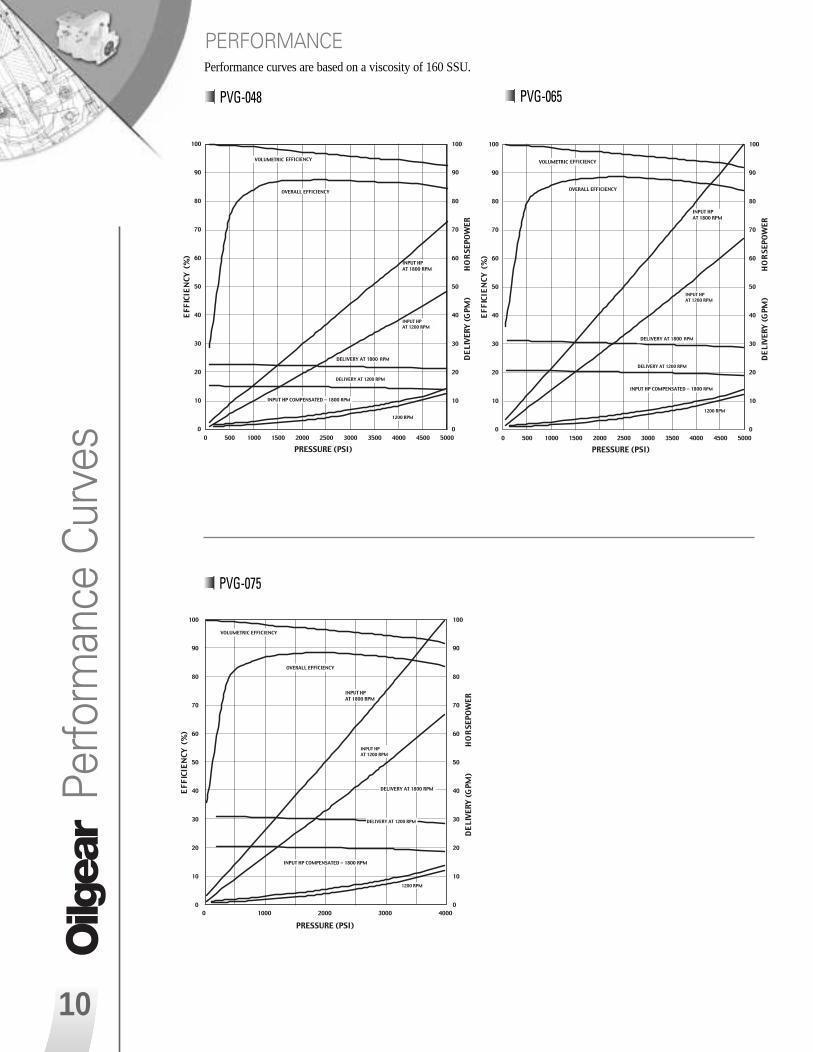
PVG-065Pe
rform
ance
Cur
ves
Performance curves are based on a viscosity of 160 SSU.
PVG-048
PVG-075
10
PERFORMANCE
OILG_1529_Bulletin_47019-G2.qxd 9/13/05 12:31 PM Page 11

..................................................................
PVG048 NOISE @ 3 ft
65
67
69
71
73
75
77
79
81
83
85
0 500 1000 1500 2000 2500 3000 3500 4000 4500 5000
HIGH PRESSURE - PSI
NO
ISE
AT
3 F
T.
- d
BA
. . . . . . 1200 RPM
1800 RPM
2400 RPM
Sound CurvesPVG-100 PVG-130
PVG-048 PVG-065
PVG065 NOISE @ 3 ft
65
67
69
71
73
75
77
79
81
83
85
0 500 1000 1500 2000 2500 3000 3500 4000 4500 5000
HIGH PRESSURE - PSI
NO
ISE
AT
3 F
T.
- d
BA
............................................................
1200 RPM
1800 RPM
2400 RPM
. . . . . .
11
Performance curves are based on a viscosity of 160 SSU.
PERFORMANCE
All of the sound curves are based on pump delivering full volume from port “A”.
SOUND
OILG_1529_Bulletin_47019-G2.qxd 9/13/05 12:31 PM Page 12

Soun
d Cu
rves
12
PVG-075 PVG-100
All of the sound curves are based on pump delivering full volume from port “A”.
SOUND
66
68
70
72
74
76
78
80
82
84
86
0 500 1000 1500 2000 2500 3000 3500 4000
HIGH PRESSURE - PSI
NO
ISE
AT
3 F
T.
- d
BA
1200 RPM
1500 RPM
1800 RPM
2100 RPM
2400 RPM
................................................. . . . . . .
66
68
70
72
74
76
78
80
82
84
86
0 500 1000 1500 2000 2500 3000 3500 4000 4500 5000
HIGH PRESSURE - PSI
NO
ISE
AT
3 F
T. -
dB
A
1200 RPM
1500 RPM
1800 RPM
2400 RPM
. . . . . .
.......................................................
PVG-130
..........
..........
..........
..........
.............
..............
..............
66
68
70
72
74
76
78
80
82
84
86
88
0 500 1000 1500 2000 2500 3000 3500 4000
HIGH PRESSURE - PSI
NO
ISE
AT
3 F
T.
- d
BA
1200 RPM
1500 RPM
1800 RPM
2400 RPM
. . . . . .
OILG_1529_Bulletin_47019-G2.qxd 9/13/05 12:31 PM Page 13

PVG-048 PVG-065
Inlet/supercharge and sound curves are based on a viscosity of 500 SSU.
INLET SUCTION/SUPERCHARGE
Inlet/Suction Curves
13
PVG-075
OILG_1529_Bulletin_47019-G2.qxd 9/13/05 12:31 PM Page 14

Inle
t/Suc
tion
Curv
esInlet/supercharge and sound curves are based on a viscosity of 500 SSU.
PVG-100 PVG-130
INLET SUCTION/SUPERCHARGE
14
OILG_1529_Bulletin_47019-G2.qxd 9/13/05 12:31 PM Page 15

HOW TO ORDER
BLOCK NUMBER1 2 3 - 4 - 5 6 7 - 8 9 10 11 - 12 - 13 14 - 15 / 16EXPLANATION
VARIABLE PUMPP V G - 100 - B1 U V - L D F Y - P - 1NN SN - NN / NNEXAMPLE
* Subject to change without notice.
How
to Order
1 = UNITP = Pump
2 = TYPEV = VariableF = Fixed
3 = DESIGN TYPEG = Type
4 = UNIT SIZE048 = 48 ml/rev.065 = 65 ml/rev.075 = 75 ml/rev.100 = 100 ml/rev.130 = 130 ml/rev.
5 = DESIGN SERIES*B1 = Series
6 = DESIGN SERIES MODIFIERU = SAE Conn. & MountingB = Metric
7 = SEALSV = Viton (Standard)B = Buna-NE = ButylP = EPR
8 = ROTATIONL = Left-hand (CCW)R = Right-hand (CW)
9 = VALVE PLATE TYPED = One-way Service;
Side Ported (thru shaft)G = One-way Service;
Side PortedS = One-way Service;
Rear Ported
10 = CONNECTION TYPEF = Flange
11 = SHAFT END DESIGNATOR(See Table 1)
12 = CONTROL TYPEN = NoneF = FixedP = Pressure CompensatingR = Solenoid Operated VolumeV = Electrohydraulic
(with feedback)
Table 1 Shaft End Designator
R CONTROL ONLY
13a = TYPEU = Two Volume Control
13b = SOLENOID VOLTAGE0 = 115/60 - 110/50 VAC1 = 230/60 - 220/50 VAC2 = 12 VDC3 = 24 VDC
13c = CONNECTORR = .500 NPT w/Out LiteW = .500 NPT w/LiteS = PG-11 w/Out LiteL = PG-11 w/Lite
V CONTROL ONLY13a = TYPE
M = With Direct Operated Servo Valve
S = With Servo Valve13b = SIZE
20 = Servo Valve Size 20 (Type M)25 = Servo Valve Size 25 (Type S)
14 = VOLUME STOPSNN = No Volume StopSA = Minimum Volume Stop
(for “V” Control Only)SB = Maximum and Minimum
Volume Stop (for “R”Control Only)
SN = Maximum Volume Stop
OMIT THE FOLLOWING IF NOTREQUIRED
15 = AUXILIARY ADAPTERSAA = Coupling & Adapter
SAE A-A (splined)AN = Coupling & Adapter
SAE A (splined)BB = Coupling & Adapter
SAE B-B (splined)BN = Coupling & Adapter
SAE B (splined)CN = Coupling & Adapter
SAE C (splined)CP = Cover plate (standard top
& bottom ported pump)NN = None
16 = OPTIONAL GEAR PUMPS05 = 0.488 cipr ( 8 ml/rev.)07 = 0.672 cipr (11ml/rev.)10 = 0.976 cipr (16 ml/rev.)14 = 1.403 cipr (23 ml/rev.)20 = 2.015 cipr (49 ml/rev.)
13 = CONTROL MODIFIER
F CONTROL ONLY075 = 75% Stroke100 = Full Stroke
P CONTROL ONLY13a = PRESSURE COMPENSATOR
OPTIONS1 = Single Setting2 = Dual SettingA = Normally Open
Proportional DeviceB = Normally Closed
Proportional DeviceC = Single Pressure with
Soft Starting, N.O.13b = SOLENOID VOLTAGE
N = None Required0 = 115/60 - 110/50 VAC1 = 230/60 - 220/50 VAC2 = 12 VDC3 = 24 VDC
13c = CONNECTORN = None RequiredR = .500 NPT w/Out Lite
*W = .500 NPT w/LiteS = PG-11 w/Out Lite*L = PG-11 w/Lite* Not Available w/P-A or P-B/ OMIT IF NOT REQUIRED
13d = CONTROL MODIFIER** F = Load Sensing Option** G = Horsepower Limiting with
Load Sensing OptionH = Horsepower Limiter OptionK = Load Sense w/Minimum
Standby OptionL = Load Sense w/Horsepower
and Minimum Standby Option
** Not Available with pressure compensator options 2, A, B or C
13e = INPUT HORSEPOWER @ 1800 RPM
Example: for size 100 or 130 limited to 100 HP Input
100 = 100 HP Input (74.6 kw)
UNIT SIZE048/065/075 100/130
Y SAE B-B Key, Full Length SAE C-C Key, Full LengthZ N/A SAE C-C Key, 1” Shorter than “Y”S SAE B-B Spline, Loose Fit SAE C-C Spline, Loose FitD SAE B-B Spline, Class 5 SAE C-C Spline, Class 5K SAE B Spine, Loose Fit SAE C Spline, Loose FitL SAE B Spline, Class 5 SAE C Spline, Class 5R SAE C Spine, Loose Fit SAE D Spline, Loose FitB SAE C Key, Full Length SAE D Key, Full Length
13a b c / d e
15
OILG_1529_Bulletin_47019-G2.qxd 9/13/05 12:31 PM Page 16

AUSTRALIAOilgear Towler Australia Pty. Ltd.
BRAZILOilgeardo Brazil Hydraulica Ltd.
CANADAThe Oilgear Company
FRANCEOilgear Towler S.A.
GERMANYOilgear Towler GmbH
INDIAOilgear Towler Polyhydron Pvt. Ltd.Towler Automation Pvt. Ltd.
ITALYOilgear Towler S.r.l.
JAPANThe Oilgear Japan Company
KOREAOilgear Towler Korea Co. Ltd.
MEXICOOilgear Mexicana S.A. de C.V.
SPAINOilgear Towler S.A.
TAIWANOilgear Towler Taiwan Co. Ltd.
UNITED KINGDOMOilgear Towler Ltd.
UNITED STATES OF AMERICAThe Oilgear Company
World HeadquartersThe Oilgear Company2300 South 51st Street Milwaukee, WI USA 53219phone: 414/327-1700 fax: 414/327-0532
www.oilgear.com
For more information about your application or the productsin this brochure, please contact your nearest Oilgear facility.
Bulletin 47019-GRevised September 2005Printed in USA
OILG_1529_Bulletin_47019-G2.qxd 9/13/05 12:30 PM Page 1


![PVG 32 Proportional Valve Group Installation Guide€¦ · LSB B A LSA P109135 Product Rated Pressure PVG 32 w. PVS 300 bar [4351 psi] PVG 32 w. PVSI 350 bar [5076 psi] PVG 32 w](https://img.pdfslide.us/doc/110x75/6061ebbf8add853ee82334b4/pvg-32-proportional-valve-group-installation-guide-lsb-b-a-lsa-p109135-product-rated.jpg)

![[PVG] B.o.B - Magic](https://img.pdfslide.us/doc/110x75/55cf8f4c550346703b9ae7e5/pvg-bob-magic.jpg)


![Evanescence - Fallen [Pvg Book]](https://img.pdfslide.us/doc/110x75/547f6bd45906b5f4288b45c0/evanescence-fallen-pvg-book.jpg)
![[PVG] Echosmith - Cool Kids](https://img.pdfslide.us/doc/110x75/55cf8de2550346703b8c4037/pvg-echosmith-cool-kids.jpg)