Embed Size (px)
DESCRIPTION
Purity Analysis : Abstract Interpretation Formulation. Ravichandhran Madhavan , G. Ramalingam, Kapil Vaswani Microsoft Research, India. Purity Analysis [ Salcianu & Rinard VMCAI ‘05, Whaley & Rinard OOPSLA ‘99]. A (side) effect analysis for the heap - PowerPoint PPT Presentation
Citation preview

Purity Analysis : Abstract Interpretation FormulationRavichandhran Madhavan, G. Ramalingam, Kapil VaswaniMicrosoft Research, India
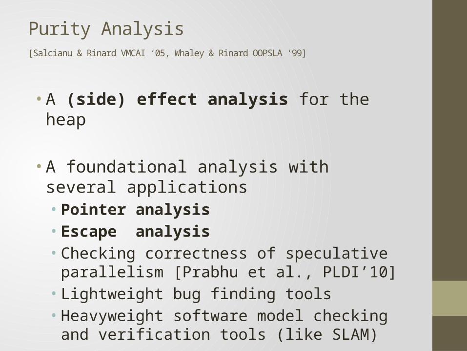
Purity Analysis
[Salcianu & Rinard VMCAI ‘05, Whaley & Rinard OOPSLA ‘99]
• A (side) effect analysis for the heap
• A foundational analysis with several applications• Pointer analysis• Escape analysis• Checking correctness of speculative parallelism
[Prabhu et al., PLDI’10]• Lightweight bug finding tools• Heavyweight software model checking and verification
tools (like SLAM)

Our Contributions
• An Abstract Interpretation formalization• A simpler explanation of the analysis• A simpler and more standard correctness proof• Helps extend and modify algorithm …• for Scalability• Precision• Functionality
• and verify correctness of extensions/modifications
• A step towards formalizing similar modular heap analyses like Lattner et al. [PLDI ‘07], Buss et al. [SAC ’08]
• 3 new optimizations with empirical evaluations

ModularHeap Effect Analysis
Problem and Challenges
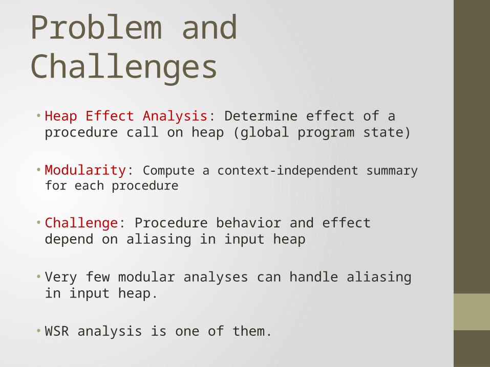
• Heap Effect Analysis: Determine effect of a procedure call on heap (global program state)
• Modularity: Compute a context-independent summary for each procedure
• Challenge: Procedure behavior and effect depend on aliasing in input heap
• Very few modular analyses can handle aliasing in input heap.
• WSR analysis is one of them.
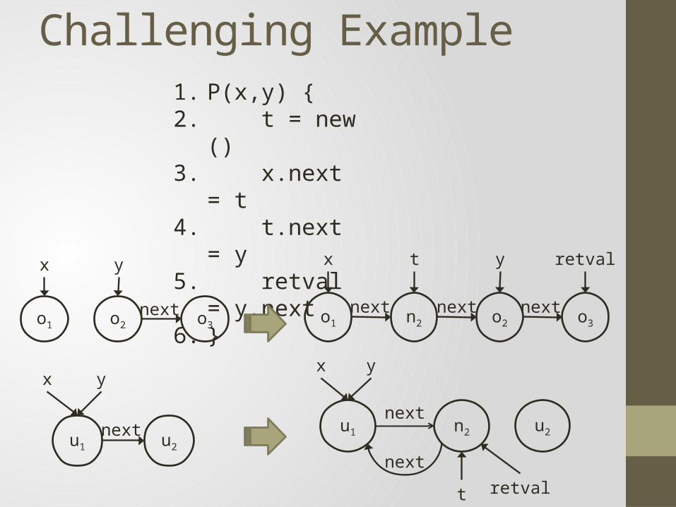
Challenging Example1. P(x,y) {2. t = new ()3. x.next = t4. t.next = y5. retval = y.next6. }
o1 o2 o3
x y
next n2o1 o2 o3
x yt retval
next next next
u1 u2
x y
next n2u1 u2
x y
t retval
next
next

Two possible Approaches
1. Compute different summaries for different aliasing configurations.• Pros: Better precision• Cons: Possible explosion in the number of summaries
2. Compute a single summary – approach taken by WSR.
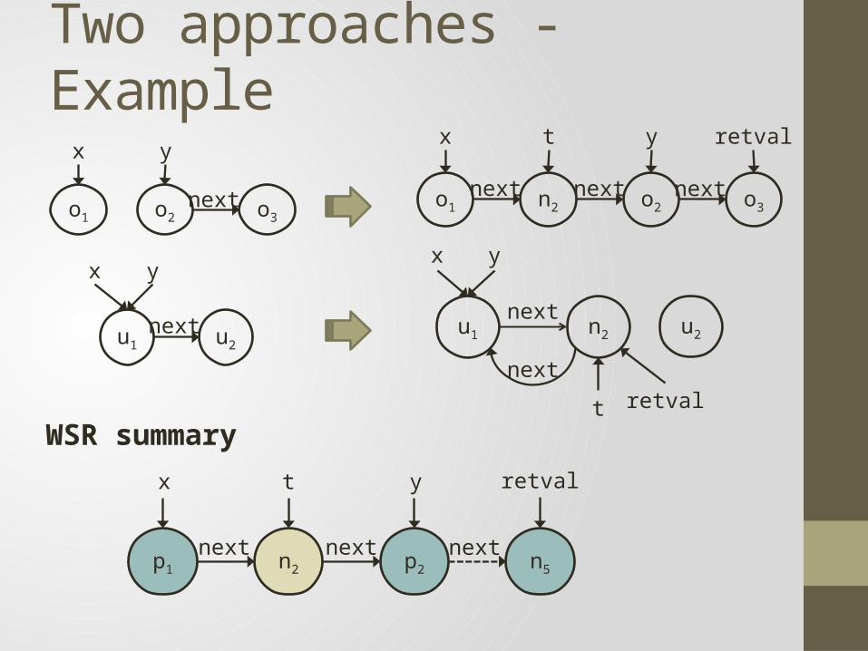
Two approaches - Example
o1 o2 o3
x y
next n2o1 o2 o3
x yt retval
next next next
u1 u2
x y
next
n2p1 p2 n5
x yt retval
next next next
WSR summary
n2u1 u2
x y
t retvalnext
next
Computing WSR Summaries
Overview
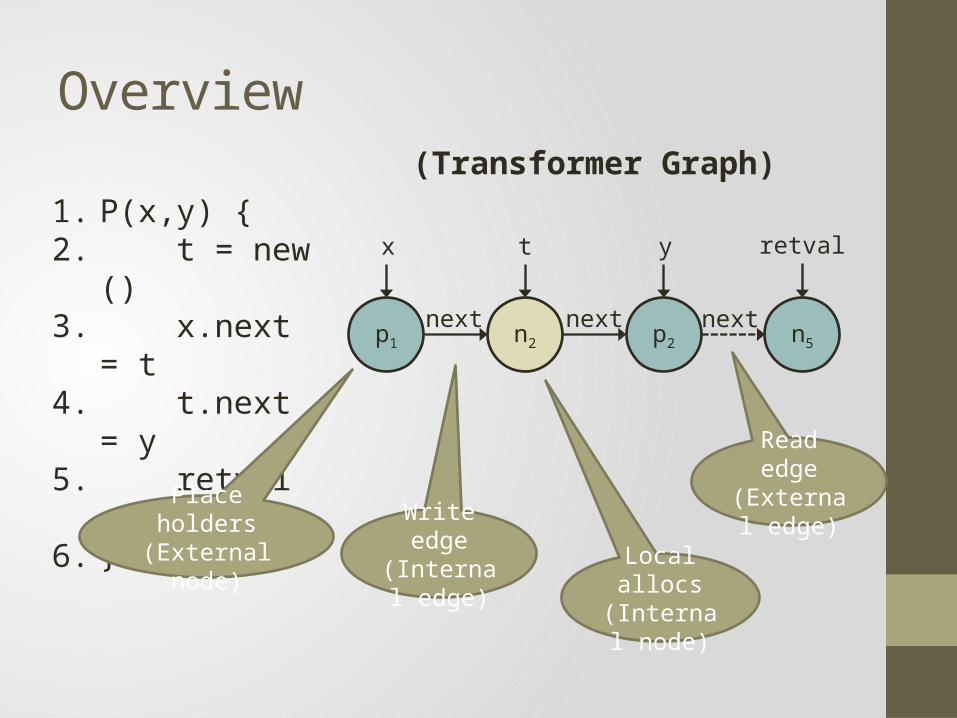
1. P(x,y) {2. t = new ()3. x.next = t4. t.next = y5. retval = y.next6. }
n2p1 p2 n5
x yt retval
next next next
(Transformer Graph)
Place holders(External node)
Read edge(External
edge)Write edge(Internal
edge) Local allocs(Internal
node)
Formalizing WSR analysis
• Like shape analyses, WSR analysis computes a graph at every program point.
• But the graphs are abstractions of state transformers rather than states.
Abstract Interpretation Formulation
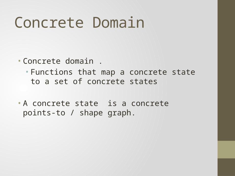
Concrete Domain
• Concrete domain .• Functions that map a concrete state to a set of
concrete states
• A concrete state is a concrete points-to / shape graph.
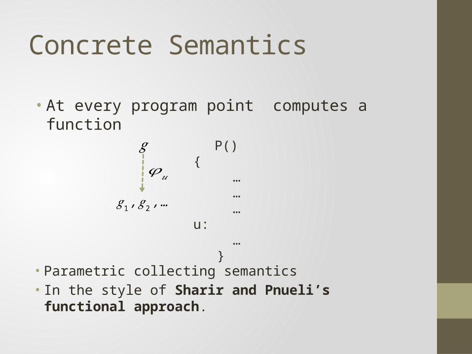
Concrete Semantics
• At every program point computes a function
P() { … … …u: … }
𝑔
𝑔1 ,𝑔2 ,…
𝜑𝑢
• Parametric collecting semantics• In the style of Sharir and Pnueli’s functional approach.
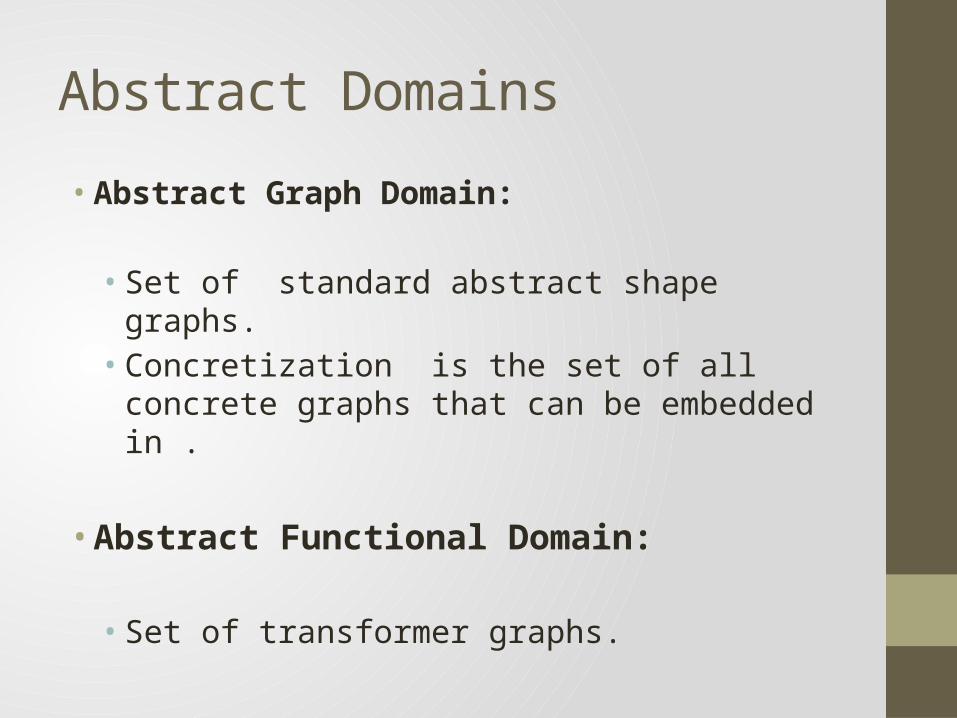
Abstract Domains
• Abstract Graph Domain:
• Set of standard abstract shape graphs. • Concretization is the set of all concrete graphs that
can be embedded in .
• Abstract Functional Domain:
• Set of transformer graphs.
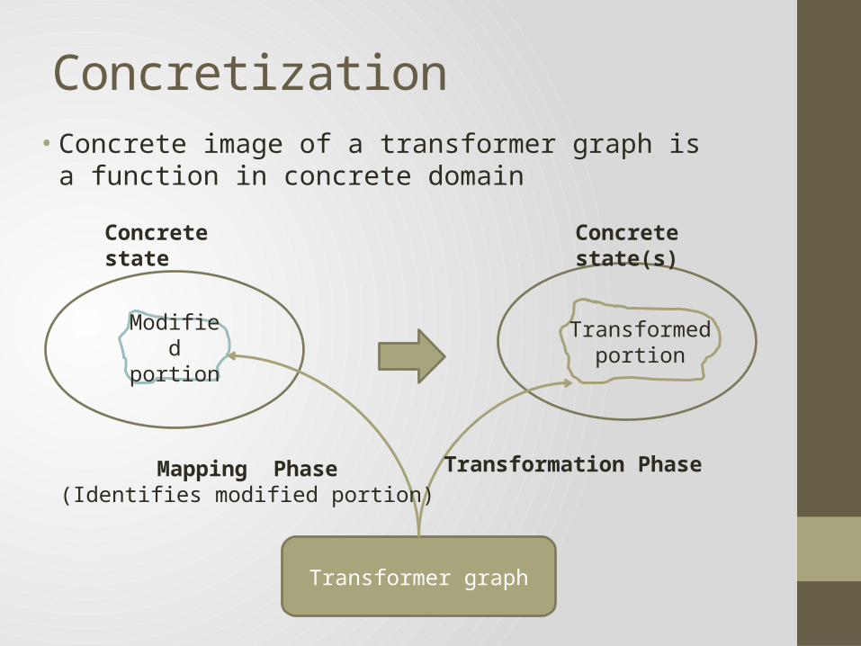
Concretization• Concrete image of a transformer graph is a function in
concrete domain
Modified portion
Transformer graph
Concrete state Concrete state(s)
Transformed portion
Mapping Phase(Identifies modified portion)
Transformation Phase
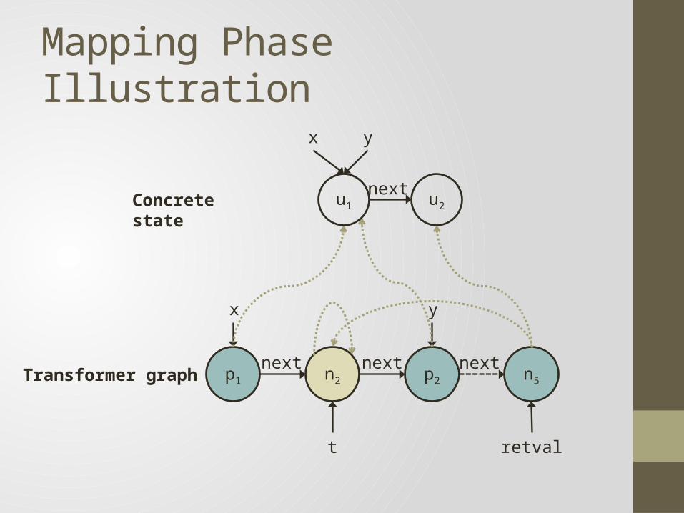
Mapping Phase Illustration
n2p1 p2 n5
x y
t retval
next next next
u1 u2
x y
nextConcrete state
Transformer graph
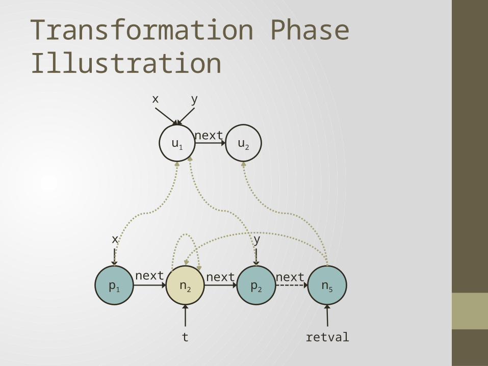
Transformation Phase Illustration
n2p1 p2 n5
x y
t retval
next next next
u1 u2
x y
next
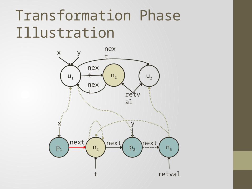
Transformation Phase Illustration
n2p1 p2 n5
x y
t retval
next next next
u1 u2
x y next
next n2
next
retval
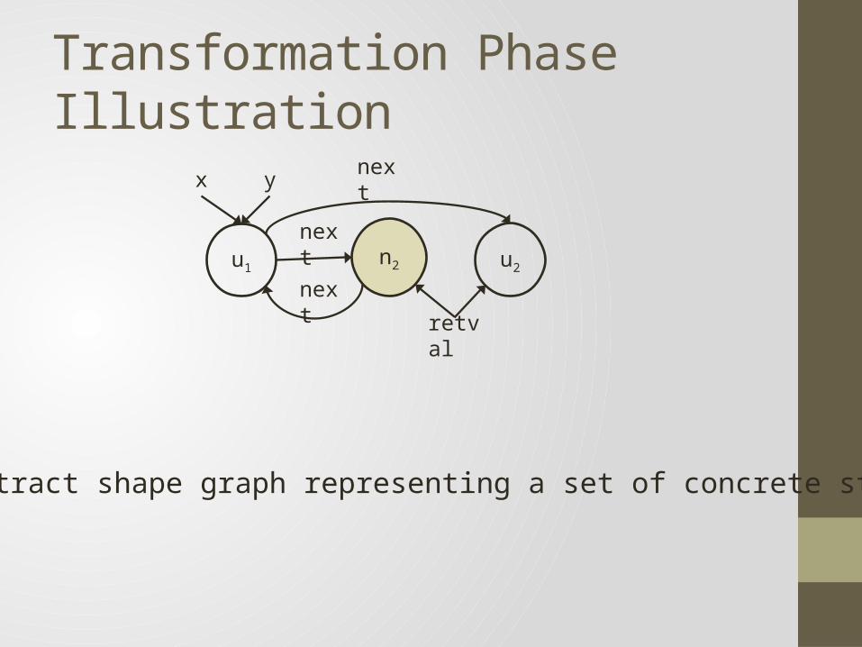
Transformation Phase Illustration
• Abstract shape graph representing a set of concrete states
u1 u2
x y next
next n2
next
retval

Abstract Vs Concrete Summary
u1 u2
x y
next
u1 u2
x y
next𝜸 (𝝉 )
Concrete summary
u1 u2
x y next
next n2
nextretval
n2u1 u2
x y
t retvalnext
next

Correctness and Termination
Partial order and join
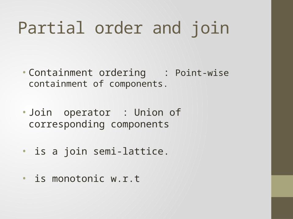
• Containment ordering : Point-wise containment of components.
• Join operator : Union of corresponding components
• is a join semi-lattice.
• is monotonic w.r.t

Abstract Semantics
• Computes a transformer graph at every program point.
• Uses a set of equations having the same structure as the concrete semantics.
• Uses the abstract transformers for statements and procedure calls.
• Handles procedure calls using the summary of the called function.
Correctness and Termination
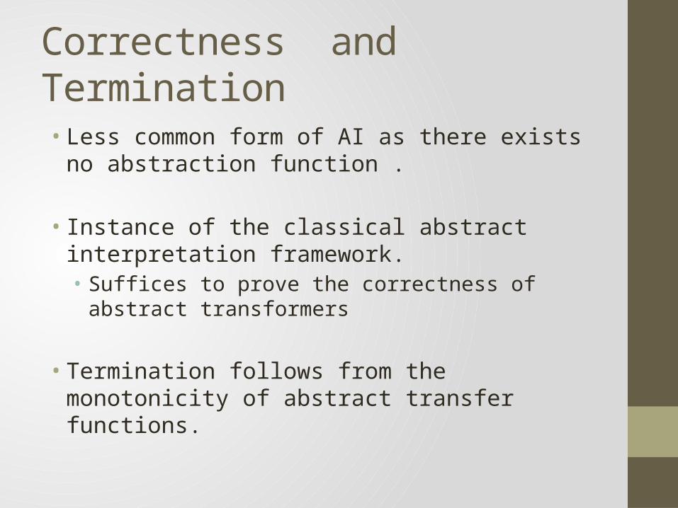
• Less common form of AI as there exists no abstraction function .
• Instance of the classical abstract interpretation framework.• Suffices to prove the correctness of abstract transformers
• Termination follows from the monotonicity of abstract transfer functions.

Optimizations
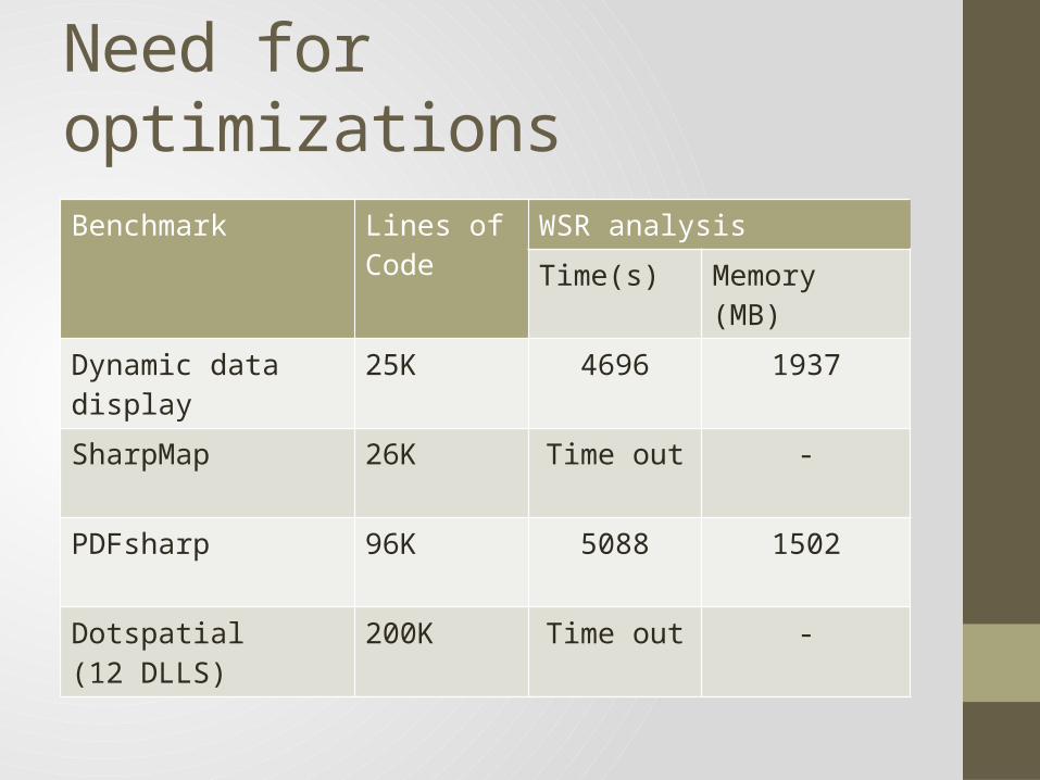
Need for optimizations
Benchmark Lines of Code
WSR analysis Time(s) Memory (MB)
Dynamic data display 25K 4696 1937
SharpMap 26K Time out -
PDFsharp 96K 5088 1502
Dotspatial (12 DLLS)
200K Time out -
Node Merging Optimization
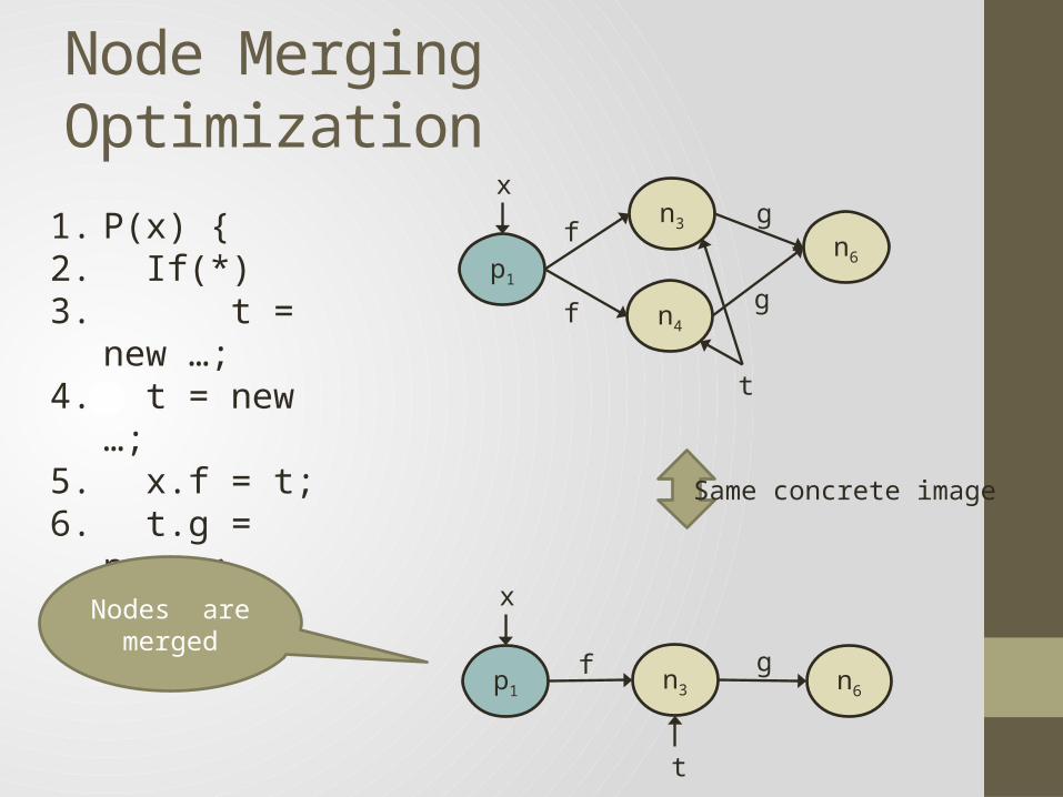
1. P(x) { 2. If(*)3. t = new …;4. t = new …;5. x.f = t;6. t.g = new …;7. } Same concrete image
Nodes are merged
n3p1 n6
x
t
f g
n3
p1
n6
x
t
f
n4f
g
g

Correctness of node merging
• Does merging arbitrary nodes in the transformer graph preserve correctness ?
• Node merging produces an embedding .
• If then concrete image of is over-approximated by the concrete image of .
Termination with node merging
• Node merging doesn’t preserve containment ordering.
• Termination is guaranteed only if merged nodes do not reappear in subsequent steps.
Termination with node merging [Cont.]
• Solution : Track (transformer graph, equivalence relation) pairs.
• The equivalence relation records nodes merged in the previous steps.
• Whenever a new node is created replace it with the representative of its equivalence class.
Identifying nodes to merge
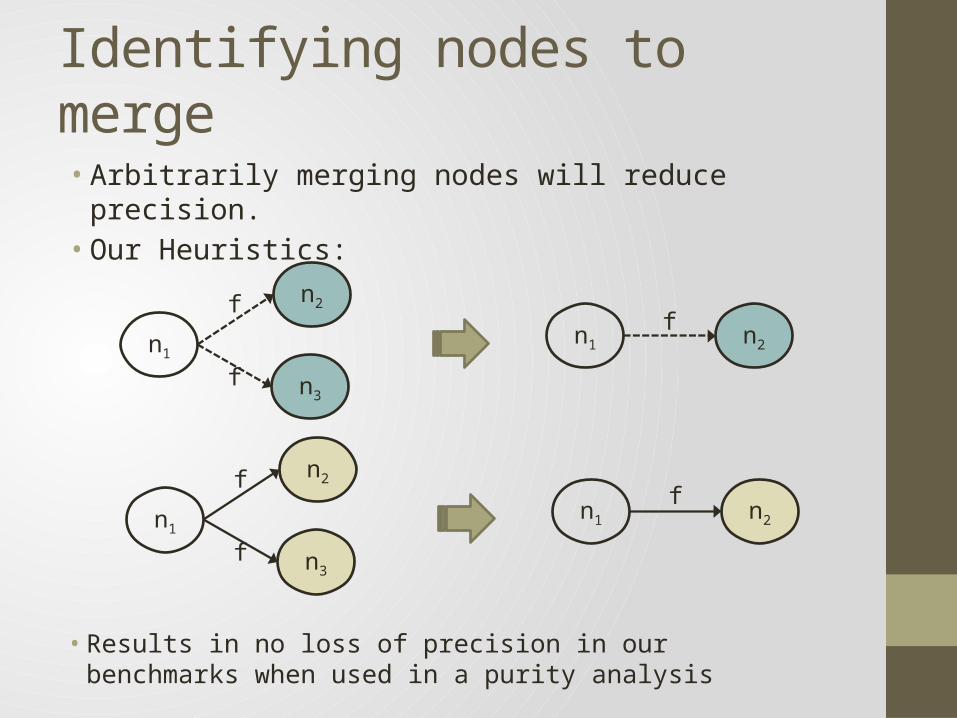
• Arbitrarily merging nodes will reduce precision.• Our Heuristics:
n2
n1
n3
f
f
n2n1f
n2
n1
n3
f
f
n2n1f
• Results in no loss of precision in our benchmarks when used in a purity analysis

Evaluation of Node mergingBenchmark Lines of
CodeWith Node merging
Time (s) Memory (MB)
Dynamic data display 25K 58 427
SharpMap 26K 615 356
PDFsharp 96K 125 535
Dotspatial (12 DLLS)
200K 963 568
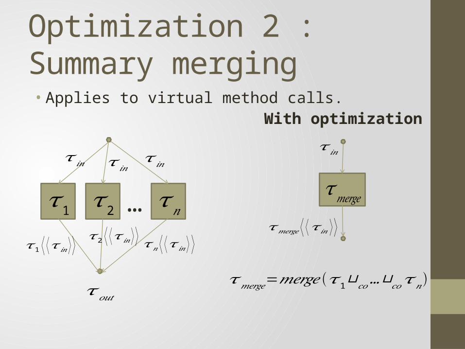
Optimization 2 : Summary merging• Applies to virtual method calls.
𝜏1 …𝜏2 𝜏𝑛
𝜏𝑜𝑢𝑡
𝜏 𝑖𝑛 𝜏 𝑖𝑛𝜏 𝑖𝑛
𝜏1 ⟨ ⟨𝜏 𝑖𝑛 ⟩ ⟩ 𝜏2 ⟨ ⟨𝜏 𝑖𝑛⟩ ⟩𝜏𝑛 ⟨ ⟨𝜏 𝑖𝑛 ⟩ ⟩
𝜏𝑚𝑒𝑟𝑔𝑒
𝜏𝑚𝑒𝑟𝑔𝑒=𝑚𝑒𝑟𝑔𝑒(𝜏1⊔𝑐𝑜…⊔𝑐𝑜𝜏𝑛)
𝜏 𝑖𝑛
𝜏𝑚𝑒𝑟𝑔𝑒 ⟨ ⟨𝜏 𝑖𝑛 ⟩ ⟩
With optimization
Optimization 3: Safe node elimination
• Removes unnecessary external nodes.
• Eg: Set::Contains is pure but its WSR summary has many external edges/nodes.
• Does not affect precision.
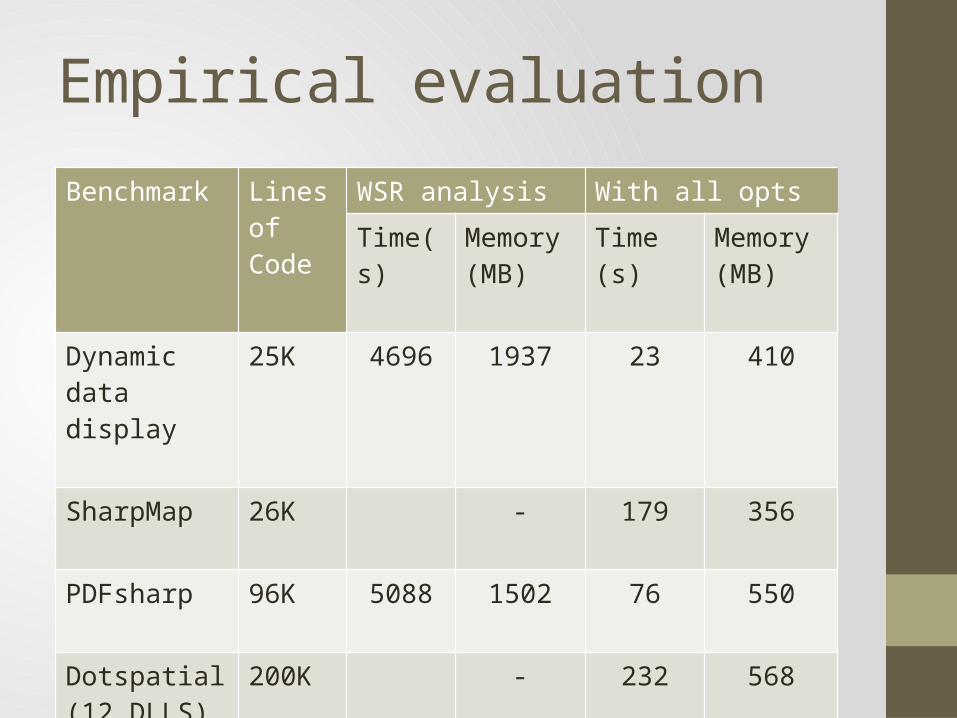
Empirical evaluation
Benchmark Lines of Code
WSR analysis With all optsTime(s) Memory
(MB)Time (s) Memory
(MB)Dynamic data display
25K 4696 1937 23 410
SharpMap 26K - 179 356
PDFsharp 96K 5088 1502 76 550
Dotspatial (12 DLLS)
200K - 232 568

Conclusion
• WSR analysis is a widely used modular heap analysis.
• Formalized WSR analysis as an Abstract Interpretation.• Mentioned as an open problem by Salcianu.
• Proposed 3 Optimizations to WSR analysis.
• Proved them correct using the AI formulation.• They make the analysis to scale to large programs.