Embed Size (px)
Citation preview

Self-cooling Motor-independent FrequencyInverter
PumpDrive 2 Eco
Application Guide

Version 1.4
Application Guide PumpDrive 2 Eco
2016-10-20 2016-11-11 PDrv2-Eco_Application_Guide_rev_1_4.docx
Page 1 of 48
Application Guide PumpDrive 2 Eco
The use cases in the application guide are only typical examples for training purposes. The examples are not cus-tomer specific solutions. The examples are not binding and can be incomplete. The examples do not cover all possi-ble eventualities. The examples do not cover all design details and variants, nor do they cover all scenarios and situ-ations that may arise during installation, operation or maintenance. The application guide is not replacing the oper-ating manual. In any case of divergence the operating manual has higher priority. The operator must take care about the appropriate operation referring to the operating manual. The examples do not excuse from the save op-erating, installation and service. Changes of this application guide will be done without announcement.

Version 1.4
Application Guide PumpDrive 2 Eco
2016-10-20 2016-11-11 PDrv2-Eco_Application_Guide_rev_1_4.docx
Page 2 of 48
1. Pre-Conditions .............................................................................................................................. 3 1.1.1 Pump characteristc curve ...................................................................................................................................... 6 1.1.2 Parameterization of Motor data............................................................................................................................. 7
2. Single pump .................................................................................................................................. 8
2.1 Single pump – Open loop control ........................................................................................................... 8 2.1.1 Open loop control: control value at display .......................................................................................................... 8 2.1.2 Open loop control: control value by external signal 0…10V ............................................................................... 9 2.1.3 Open loop control: control value by external signal 4…20mA ...........................................................................10 2.1.4 Open loop control: digital motor potentiometer ...................................................................................................11
2.2 Single pump – closed loop control ........................................................................................................ 12 2.2.1 Closed loop control: Differential pressure with PumpMeter (Modbus) ...............................................................12 2.2.2 Closed loop control: differential pressure with sensor 4…20mA ........................................................................13 2.2.3 Closed loop control: differential pressure with sensor 4…20mA set point via analog input ...............................14 2.2.4 Closed loop control: differential pressure with 2 pressure sensors 4...20 mA .....................................................15 2.2.5 Closed loop control: Sensorless differential pressure control ..............................................................................16 2.2.6 Closed loop control: pressure with pressure sensor 4...20 mA ............................................................................17 2.2.7 Closed loop control: Pressure with PumpMeter (Modbus) ..................................................................................18 2.2.8 Closed loop control: Pressure with Pressure sensor 0...10 V ...............................................................................19 2.2.9 Closed loop control: Pressure, Set point (closed loop) at analog input 0…10V ..................................................20 2.2.10 Closed loop control: constant level at low pressure side with submersible sensor 4…20mA .........................21 2.2.11 Closed loop control: temperature with thermometer 4…20mA ......................................................................22 2.2.12 Closed loop control: Flow rate with flow rate sensor 4…20mA .....................................................................23
3. Double pump ............................................................................................................................... 24
3.1 Double pump – Open loop control ....................................................................................................... 24 3.1.1 Open loop control: control value at display .........................................................................................................24 3.1.2 Open loop control: control value with external signal .........................................................................................26
3.2 Double pump – closed loop control ...................................................................................................... 28 3.2.1 Closed loop control non redundant: differential pressure with PumpMeter (Modbus) – typical application ......28 3.2.2 Closed loop control redundant: differential pressure with PumpMeter (Modbus) ...............................................30 3.2.3 Closed loop control redundant: Discharge pressure with sensor 4…20mA and PumpMeter each pump ............32 3.2.4 Closed loop control redundant: Discharge pressure with pressure sensor 4…20mA via M12 ............................35
4. Pump functionality ...................................................................................................................... 38
4.1 Closed loop control ................................................................................................................................ 38 4.1.1 Closed loop control: dynamic differential pressure set point compensation based on flow rate estimation ........38 4.1.2 Closed loop control: dynamic differential pressure set point compensation based on speed ...............................40 4.1.3 Open loop control: 1 fix speed selected by digital switches or variable speed via analog signal ........................41 4.1.4 Closed loop control: sleep Mode .........................................................................................................................42
5. M12 Cable .................................................................................................................................... 43
5.1 Bus cable for connecting PumpMeter to the M12-Module ................................................................ 43
5.2 Bus cable for Double- and Multi Pump Operation ............................................................................. 44
5.3 Crosslink cable ....................................................................................................................................... 45
5.4 M12 Cable for fieldbus module Modbus RTU .................................................................................... 46
6. Project ......................................................................................................................................... 47
7. Other documents ........................................................................................................................ 48
Version 1.4
Application Guide PumpDrive 2 Eco
2016-10-20 2016-11-11 PDrv2-Eco_Application_Guide_rev_1_4.docx
Page 3 of 48
1. Pre-Conditions
- The motor data are set according to the operating manual. - The motor control is correct selected and suits to the motor. - The pump curves are stored in the drive.
Pre-settings from production Pumps with PumpDrive are delivered with the following pre-settings:
Motor data Motion control according to motor type Pre-setting of PumpMeter including sensors Pump curves
Type series Etaline / Etaline Z Etanorm, Etabloc, Etachrom Multitec, Movitec, Sewatec
Retrofit Drive PumpDrive spare part
selection EasySelect EasySelect EasySelect Material number
Motor data preset preset Preset -
Asynchronous motor Vector ASM Vector ASM Vector ASM -
SuPremE Vector SuPremE Vector SuPremE Vector SuPremE Vector SuPremE
with PumpMeter Closed loop control: Differen-tial pressure and sensors pre-set
Closed loop control: pressure p constant and sensors preset
- -
without PumpMeter Open-loop Control Open-loop Control Open-loop Control Open-loop Control
Pump curve preset preset - -
Setpoint with PumpMeter: preset with PumpMeter: preset - -
Retrofit PumpDrives, which will be selected in EasySelect, will be delivered only with motor data (work is in progress). The pump curves must be parameterized on site, can be uploaded from PumpMeter, can be set from ServiceTool or display. PumpDrives (spare parts), which are ordered by material numbers are not parameterized in the production. Using a 0/4…20mA or 0/2…10V Sensor for control a PumpMeter can be used as internal sensor in parallel. PumpMeter used as internal sensor improves the flow estimation.

Version 1.4
Application Guide PumpDrive 2 Eco
2016-10-20 2016-11-11 PDrv2-Eco_Application_Guide_rev_1_4.docx
Page 4 of 48
L1 L2 L3
LINE
PE U V W
MOTOR
PTC
MOTOR
PE -
L1L2L3N
PE
1 23
4
5M
3~
BR+
6 6
L1 L2 L3
LINE
PE U V W
MOTOR
PTC
MOTOR
PE -
L1L2L3N
PE
1 23
4
5M
3~
BR+
6 6
L1 L2 L3
LINE
PE U V W
MOTOR
PTC
MOTOR
PE -
L1L2L3N
PE
1 2
3
4
5M
3~
BR+
6
Connecting mains and motor Size A (0,37 kW – 1,5 kW) Size B (2,2 kW – 4 kW)
Size C (5,5 kW – 11 kW)
Nr. Function
1 Mains connection
2 Motor connection
3 PTC connection
4 Brake
5 Motor PTC
6 Jumper for IT mains
Nr. Function
1 Mains connection
2 Motor connection
3 PTC connection
4 Brake
5 Motor PTC
6 Jumper for IT mains
Nr. Function
1 Mains connection
2 Motor connection
3 PTC connection
4 Brake
5 Motor PTC
6 Jumper for IT mains

Version 1.4
Application Guide PumpDrive 2 Eco
2016-10-20 2016-11-11 PDrv2-Eco_Application_Guide_rev_1_4.docx
Page 5 of 48
2 4 3 21/min
P 1.1.1.
0 0 0 0
P 1.1.1.
Standard Display For the parameterization of the following applications the user must be logged in Customer Level. Customer Login in Favourite Menu:
By pressing the button OK Taste the user selects the Favourite Menu, where the main parameters can be changed. By pressing up and down buttons, the user can navigate through the Favourite Menu. Settings:
By pressing ESC and OK at the same time, the user selects the first menu level, where he can navigate through the different menus and parameters.
Main Screen
Favourite Menu First Parameter: 1-1-1 Login
Type in PIN: 0000
4 x
A screw driver is displayed after successful login
Favourite Menu

Version 1.4
Application Guide PumpDrive 2 Eco
2016-10-20 2016-11-11 PDrv2-Eco_Application_Guide_rev_1_4.docx
Page 6 of 48
1.1.1 Pump characteristic curve
The pump characteristic curve for an Etaline 040-040-160 with full impeller diameter 174 has to been set manually. The values for the pump characteristic curves are readout of the type series booklet at nominal speed of the pump with impeller diameter 174.
Nr. Parameter Change value to Pre-settings by factory 2) Changeable by
3-4-3-1 Flow Rate Q_0 0.0 [m³/h] Preset: 0,0 m3/h ServiceTool
3-4-3-2 Flow Rate Q_1 10.0 [m³/h] Preset: 10,1 m3/h ServiceTool 3-4-3-3 Flow Rate Q_2 20.0 [m³/h] Preset: 20,3 m3/h ServiceTool 3-4-3-4 Flow Rate Q_3 30.0 [m³/h] Preset: 30,5 m3/h ServiceTool 3-4-3-5 Flow Rate Q_4 40.0 [m³/h] Preset: 40,6 m3/h ServiceTool 3-4-3-6 Flow Rate Q_5 50.0 [m³/h] Preset: 50,8 m3/h ServiceTool 3-4-3-7 Flow Rate Q_6 60.0 [m³/h] Preset: 60,9 m3/h ServiceTool 3-4-3-8 Flow Rate Q_opt 35.0 [m³/h] Preset: 35,0 m3/h ServiceTool 3-4-3-9 Pump Input Power P_0 1.50 [kW] Preset: 1,52 kW ServiceTool 3-4-3-10 Pump Input Power P_1 2.50 [kW] Preset: 2,62 kW ServiceTool 3-4-3-11 Pump Input Power P_2 3.50 [kW] Preset: 3,73 kW ServiceTool 3-4-3-12 Pump Input Power P_3 4.50 [kW] Preset: 4,64 kW ServiceTool 3-4-3-13 Pump Input Power P_4 5.20 [kW] Preset: 5,39 kW ServiceTool 3-4-3-14 Pump Input Power P_5 5.70 [kW] Preset: 5,97 kW ServiceTool 3-4-3-15 Pump Input Power P_6 6.00 [kW] Preset: 6,34 kW ServiceTool 3-4-3-16 Head H_0 42.00 [m] Preset: 43,06 m ServiceTool 3-4-3-17 Head H_1 41,80 [m] Preset: 42,89 m ServiceTool 3-4-3-18 Head H_2 40.00 [m] Preset: 41,41 m ServiceTool 3-4-3-19 Head H_3 36.00 [m] Preset: 37,48 m ServiceTool 3-4-3-20 Head H_4 31.00 [m] Preset: 32,45 m ServiceTool 3-4-3-21 Head H_5 25.00 [m] Preset: 25,88 m ServiceTool 3-4-3-22 Head H_6 16.00 [m] Preset: 16,88 m ServiceTool 3-4-3-30 Low Flow Limit Flow Rate in %
Qopt 30 [%] Preset ServiceTool
2) Pre-settings for completely assembled pump, motor, drive

Version 1.4
Application Guide PumpDrive 2 Eco
2016-10-20 2016-11-11 PDrv2-Eco_Application_Guide_rev_1_4.docx
Page 7 of 48
1.1.2 Parameterization of Motor data
A PumpDrive 2 is parameterized for a 2 pole SuPremE Motor. The pump rotation is clockwise. Name plate of motors:
Nr. Parameter Change value to Pre-settings by factory 2) Changeable by
3-2-1-1 Nominal Motor Power 0.55 [kW] Preset: 0.55 [kW] ServiceTool, Display
3-2-1-2 Nominal Motor Voltage 374 [V] Preset: 400 [V] ServiceTool, Display
3-2-1-3 Nominal Motor Frequency 50.0 [Hz] Preset: 50.0 [Hz] ServiceTool, Display
3-2-1-4 Nominal Motor Current 1.60 [A] Preset: 1.60 [A] ServiceTool, Display
3-2-1-5 Nominal Motor Speed 1500 [1/min] Preset: 1500 [1/min] ServiceTool, Display
3-2-1-6 Nominal Cos Phi Value 0.67 Preset: 0.57 ServiceTool, Display
3-2-2-1 Minimum Motor Speed 500 [1/min] Preset: 500 [1/min] ServiceTool, Display
3-2-2-2 Maximum Motor Speed 1500 [1/min] Preset: 1500 [1/min] ServiceTool, Display
3-2-3-1 PTC Data Analysis 1 = ON Preset: ON ServiceTool, Display
3-2-3-2 Thermal Motor Protection Be-haviour
Non-self-acknowledging Preset: Non-self-acknowledg-ing
ServiceTool
3-2-4 Motor Direction of Rotation 0 = Clockwise4) Preset: Clockwise ServiceTool, Display
3-3-1 Motor Control Method Vector SuPremE Preset: SuPremE Vector Con-trol
ServiceTool
3-3-4-1 Update Motor Parameters Run Preset ServiceTool
2) Pre-settings for completely assembled pump, motor, drive 4) Pump dependent

Version 1.4
Application Guide PumpDrive 2 Eco
2016-10-20 2016-11-11 PDrv2-Eco_Application_Guide_rev_1_4.docx
Page 8 of 48
16
18+24V
DI18
DO1616
DI-EN+24V
GND
DI3
DI2DI1
+24V
DICOM
AO-GND
AO
AIN2
NO
+24V
GND
COM+24V
B1
B2
B3
B4
B5
B6
B7
B8
B9
B10
A1
A2
A3
A4
A5
A6
A7
A8
A9
A10
GND
GNDAIN1
+24V
17 GND 1717GND
DO111111
2. Single pump
2.1 Single pump – Open loop control
2.1.1 Open loop control: control value at display
A fixed speed of 2000 1/min should be set on the display. The nominal speed of the 2 pole motor is 2950 1/min.
2000 1/min
Nr. Parameter Change value to Pre-settings by factory 2)
Changeable by
3-6-1 Type of Control 0 = OFF (Open-loop Con-trol)
preset ServiceTool, Display
3-2-2-1 Minimum Motor Speed 500 [1/min] preset ServiceTool, Display
3-2-2-2 Maximum Motor Speed 2950 [1/min] preset ServiceTool, Display
1-3-3 Control Value (Open-loop Control) 2000 [1/min] motor specific ServiceTool, Display
3-8-6-1 Digital Input 1 Function System Start1) preset ServiceTool
1) Digital Input 1 is set as at the factory as system start. If a digital input is set as system start, the parameter 1-3-1 System start is auto-matically without function (see control point concept in operating manual) 2) Pre-settings for completely assembled pump, motor, drive
Nr. Function
16 Enable power electronic
17 Ground for digital inputs
11 System start with DI11)
18 Alarm
PDrv 2 Eco Or local Or PLC drive

Version 1.4
Application Guide PumpDrive 2 Eco
2016-10-20 2016-11-11 PDrv2-Eco_Application_Guide_rev_1_4.docx
Page 9 of 48
16
17
18+24V
DI18
DO
GND
16
17
16
17GND
2 2AO: 0...10V0...10V
11
DI-EN+24V
GND
DI3
DI2DI1
+24V
DICOM
AO-GND
AO
AIN2
NO
+24V
GND
COM+24V
B1
B2
B3
B4
B5
B6
B7
B8
B9
B10
A1
A2
A3
A4
A5
A6
A7
A8
A9
A10
GND
GNDAIN1
+24V
DO 11
0V (GND) AO: OUT 0V(GND)
11
2.1.2 Open loop control: control value by external signal 0…10V
A fixed speed of 2000 1/min should be given by an external signal 0…10V at analog input 1. 2000 1/min is equal to 6,78 V when using a 2-pole motor with a nominal speed of 2950 1/min. Information: the set point can’t be lower than the minimum speed.
6,78V
2000 1/min
2
Nr. Parameter Change value to Pre-settings by factory 2)
Changeable by
3-6-1 Type of Control 0 = OFF (Open-loop Control) preset ServiceTool, Display
3-2-2-1 Minimum Motor Speed 500 [1/min] preset ServiceTool, Display
3-2-2-2 Maximum Motor Speed 2950 [1/min] preset ServiceTool, Display
3-8-1-1 Analog Input 1 Signal 4 = 0…10V 0 = Off ServiceTool, Display
3-8-1-2 Analog Input 1 Function 1 = Setpoint/Control value (Auto)
0 = No Function ServiceTool, Display
3-8-1-3 Analog Input 1 Lower Limit 0 [1/min] - ServiceTool, Display
3-8-1-4 Analog Input 1 Upper Limit 2950 [1/min] - ServiceTool, Display
3-8-6-1 Digital Input 1 Function System Start1) preset ServiceTool
1) Digital Input 1 is set as at the factory as system start. If a digital input is set as system start, the parameter 1-3-1 System start is auto-matically without function (see control point concept in operating manual) 2) Pre-settings for completely assembled pump, motor, drive
Nr. Function
16 Enable power electronic
17 Ground for digital inputs
11 System start with DI11)
2 Set point (open loop): external signal0...10V
18 Alarm
PDrv 2 Eco Or local Or PLC drive

Version 1.4
Application Guide PumpDrive 2 Eco
2016-10-20 2016-11-11 PDrv2-Eco_Application_Guide_rev_1_4.docx
Page 10 of 48
16
17
18+24V
DI18
DO
GND
16
17
16
17GND
2 2AO: 4...20mA4...20mA
11
DI-EN+24V
GND
DI3
DI2DI1
+24V
DICOM
AO-GND
AO
AIN2
NO
+24V
GND
COM+24V
B1
B2
B3
B4
B5
B6
B7
B8
B9
B10
A1
A2
A3
A4
A5
A6
A7
A8
A9
A10
GND
GNDAIN1
+24V
DO 11
0V (GND) AO: OUT 0V(GND)
15AIN
GND
11
14,85 mA
2000 1/min
2
2.1.3 Open loop control: control value by external signal 4…20mA
A fixed speed of 2000 1/min should be given by an external signal 4…20mA at analog input 1. The feedback of the speed should be send by analog output to a PLC. 2000 1/min is equal to 14,85 mA when using a 2-pole motor with a nominal speed of 2950 1/min (16mA / 2950 rpm * 2000 rpm + 4 mA = 14,85 mA). Information: the set point can’t be lower than the minimum speed
Nr. Parameter Change value to Pre-settings by fac-tory 2)
Changeable by
3-6-1 Type of Control 0 = OFF (Open-loop Control) preset ServiceTool, Display
3-2-2-1 Minimum Motor Speed 500 [1/min] preset ServiceTool, Display
3-2-2-2 Maximum Motor Speed 2950 [1/min] preset ServiceTool, Display
3-8-1-1 Analog Input 1 Signal 1 = 4…20mA 0 = Off ServiceTool, Display
3-8-1-2 Analog Input 1 Function 1 = Setpoint/Control value (Auto)
0 = No Function ServiceTool, Display
3-8-1-3 Analog Input 1 Lower Limit 0 [1/min] - ServiceTool, Display
3-8-1-4 Analog Input 1 Upper Limit 2950 [1/min] - ServiceTool, Display
3-8-7-1 Assignment 1 Analog Output 1 Motor speed preset ServiceTool
3-8-6-1 Digital Input 1 Function System Start1) preset ServiceTool
1) Digital Input 1 is set as at the factory as system start. If a digital input is set as system start, the parameter 1-3-1 System start is auto-matically without function (see control point concept in operating manual) 2) Pre-settings for completely assembled pump, motor, drive
Nr. Function
16 Enable power electronic
17 Ground for digital inputs
11 System start with DI11)
15 Analog output: speed
2 Set point (open loop): external signal4...20mA
18 Alarm
PDrv2 Eco Or local Or PLC drive

Version 1.4
Application Guide PumpDrive 2 Eco
2016-10-20 2016-11-11 PDrv2-Eco_Application_Guide_rev_1_4.docx
Page 11 of 48
16
17
18+24V
DI18
DO
GND
16
17
16
17GND
DO
DO 12
13
12
13
11
DI-EN+24V
GND
DI3
DI2DI1
+24V
DICOM
AO-GND
AO
AIN2
NO
+24V
GND
COM+24V
B1
B2
B3
B4
B5
B6
B7
B8
B9
B10
A1
A2
A3
A4
A5
A6
A7
A8
A9
A10
GND
GNDAIN1
+24V
DO 1111
2.1.4 Open loop control: digital motor potentiometer
A fixed speed of 2000 1/min should be changeable by the digital inputs with an increment of 10 [1/min].
13
12
+/- 2000 1/min
Nr. Parameter Change value to Pre-settings by factory 2)
Changeable by
3-6-1 Type of Control 0 = OFF (Open-loop Control) preset ServiceTool, Display
3-2-2-1 Minimum Motor Speed 500 [1/min] preset ServiceTool, Display
3-2-2-2 Maximum Motor Speed 2950 [1/min] preset ServiceTool, Display
1-3-3 Control Value (Open-loop Control) 2000 [1/min] motor specific ServiceTool, Display
3-8-6-2 Digital Input 2 Function Potentiometer Auto - No Function ServiceTool 3-8-6-3 Digital Input 3 Function Potentiometer Auto + No Function ServiceTool 3-6-6-2 Speed Change Increment 10 [1/min] preset ServiceTool 3-8-6-1 Digital Input 1 Function System Start1) preset ServiceTool
1) Digital Input 1 is set as at the factory as system start. If a digital input is set as system start, the parameter 1-3-1 System start is auto-matically without function (see control point concept in operating manual) 2) Pre-settings for completely assembled pump, motor, drive
Nr. Function
16 Enable power electronic
17 Ground for digital inputs
13 DI3: Increase speed
12 DI2: Decrease speed
11 System start with DI11)
18 Alarm
PDrv 2 Eco Or local Or PLC drive

Version 1.4
Application Guide PumpDrive 2 Eco
2016-10-20 2016-11-11 PDrv2-Eco_Application_Guide_rev_1_4.docx
Page 12 of 48
16DO
1616DI-EN+24V
GND
DI3
DI2DI1
+24V
DICOM
AO-GND
AO
AIN2
NO
+24V
GND
COM+24V
B1
B2
B3
B4
B5
B6
B7
B8
B9
B10
A1
A2
A3
A4
A5
A6
A7
A8
A9
A10
GND
GNDAIN1
+24V
18+24V
DI18
17 GND 1717GND
11DO
111170
80
4
DC
BA
2.2 Single pump – closed loop control
2.2.1 Closed loop control: Differential pressure with PumpMeter (Modbus)
A constant differential pressure of 4 bar is needed. PumpMeter is used as a differential pressure sensor in the measurement range of -1 … 10 bar. PumpMeter is connected by Modbus to the M12 Module of the drive. The set point is given by the display.
Δp
4
A
Nr. Parameter Change value to Pre-settings by factory 2) Changeable by
3-6-1 Type of Control 3 = Differential Pressure preset - see chapter 1 ServiceTool, Display
3-11-2-1 Minimum Pressure -1.00 [bar] preset ServiceTool
3-11-2-2 Maximum Pressure 10.00 [bar] preset ServiceTool
3-11-2-3 Pressure Unit bar preset ServiceTool
1-3-2 Setpoint (Closed-loop Control) 4.00 [bar] preset acc. specified Q,H ServiceTool, Display
3-8-4-1 Function M12 Module Input A 1 = PMtr Suction/Dis-charge Pressure
preset ServiceTool, Display
3-8-6-1 Digital Input 1 Function System Start1) preset ServiceTool
1) Digital Input 1 is set as at the factory as system start. If a digital input is set as system start, the parameter 1-3-1 System start is auto-matically without function (see control point concept in operating manual) 2) Pre-settings for completely assembled pump, motor, drive and PumpMeter
Nr. Function
16 Enable power electronic
17 Ground for digital inputs
11 System start with DI11)
18 Alarm
4 Actual value: tailor-made bus cable for the connection of Pump-Meter to the M12 Module (color: black, female: straight, male: an-gled)
Nr. Function
70 M12 Module: Double and multi pump operation
80 M12 Module: PumpMeter
A M12 Module female A: connection PumpMeter (Modbus)
B -
C -
D -
PDrv 2 Eco Or local Or PLC drive

Version 1.4
Application Guide PumpDrive 2 Eco
2016-10-20 2016-11-11 PDrv2-Eco_Application_Guide_rev_1_4.docx
Page 13 of 48
16DO
1616
18+24V
DI18
2
DI-EN+24V
GND
DI3
DI2DI1
+24V
DICOM
AO-GND
AO
AIN2
NO
+24V
GND
COM+24V
B1
B2
B3
B4
B5
B6
B7
B8
B9
B10
A1
A2
A3
A4
A5
A6
A7
A8
A9
A10
GND
GNDAIN1
+24V
17 GND 1717GND
11DO 11
11
2.2.2 Closed loop control: differential pressure with sensor 4…20mA
A constant differential pressure of 4 bar is needed. The 4…20mA differential pressure sensor with a measurement range of 0-6 bar is connected to analog input 2. The set point is given by the display
Δp
2
Nr. Parameter Change value to Pre-settings by fac-tory 2)
Changeable by
3-6-1 Type of Control 3 = Differential Pressure 0 = OFF (Open-loop Control)
ServiceTool, Display
3-11-2-1 Minimum Pressure -1.00 [bar] -1,00 [bar] ServiceTool
3-11-2-2 Maximum Pressure 6.00 [bar] 999,99 [bar] ServiceTool
3-11-2-3 Pressure Unit bar preset ServiceTool
1-3-2 Setpoint (Closed-loop Control) 4.00 [bar] 0,00 [bar] ServiceTool, Display
3-8-2-1 Analog Input 2 Signal 1 = 4…20mA 0 = Off ServiceTool, Display
3-8-2-2 Analog Input 2 Function 6 = Differential Pressure 0 = No Function ServiceTool, Display
3-8-2-3 Analog Input 2 Lower Limit -1.00 [bar] - ServiceTool, Display
3-8-2-4 Analog Input 2 Upper Limit 6.00 [bar] - ServiceTool, Display
3-8-6-1 Digital Input 1 Function System Start1) preset ServiceTool
1) Digital Input 1 is set as at the factory as system start. If a digital input is set as system start, the parameter 1-3-1 System start is auto-matically without function (see control point concept in operating manual) 2) Pre-settings for completely assembled pump, motor, drive
Nr. Function
16 Enable power electronic
17 Ground for digital inputs
11 System start with DI11)
2 Actual value: differential pressure sensor 4...20mA
18 Alarm
PDrv 2 Eco Or local Or PLC Drive

Version 1.4
Application Guide PumpDrive 2 Eco
2016-10-20 2016-11-11 PDrv2-Eco_Application_Guide_rev_1_4.docx
Page 14 of 48
16
17
DO
GND
16
17
16
17GND
18+24V
DI18
11
DI-EN+24V
GND
DI3
DI2DI1
+24V
DICOM
AO-GND
AO
AIN2
NO
+24V
GND
COM+24V
B1
B2
B3
B4
B5
B6
B7
B8
B9
B10
A1
A2
A3
A4
A5
A6
A7
A8
A9
A10
GND
GNDAIN1
+24V
2
DO 11
1 1AO: 0...10V0...10V
0V (GND) AO: OUT 0V(GND)
11
2.2.3 Closed loop control: differential pressure with sensor 4…20mA set point via analog input
A constant differential pressure of 4 bar is needed. The 4…20mA differential pressure sensor with a measurement range of 0-6 bar is connected to analog input 2. The set point is given via analog input 1 by a voltage 0…10V signal. The set point is 4 bar is equivalent to 6,66V (10V/6bar*4bar). Info: the set point via analog input has a higher priority than the set point via display.
Δp6,66 V
1
2
Nr. Parameter Change value to Pre-settings by factory 2)
Changeable by
3-6-1 Type of Control 3 = Differential Pressure 0 = OFF (Open-loop Control)
ServiceTool, Display
3-11-2-1 Minimum Pressure 0.00 [bar] -1,00 [bar] ServiceTool
3-11-2-2 Maximum Pressure 6.00 [bar] 999,99 [bar] ServiceTool
3-11-2-3 Pressure Unit bar preset ServiceTool
3-8-1-1 Analog Input 1 Signal 4 = 0…10V 0 = Off ServiceTool, Display
3-8-1-2 Analog Input 1 Function 1 = Setpoint/Control value (Auto)
0 = No Function ServiceTool, Display
3-8-1-3 Analog Input 1 Lower Limit 0.00 [bar] - ServiceTool, Display
3-8-1-4 Analog Input 1 Upper Limit 6.00 [bar] - ServiceTool, Display
3-8-2-1 Analog Input 2 Signal 1 = 4…20mA 0 = Off ServiceTool, Display
3-8-2-2 Analog Input 2 Function 6 = Differential Pressure 0 = No Function ServiceTool, Display
3-8-2-3 Analog Input 2 Lower Limit 0.00 [bar] - ServiceTool, Display
3-8-2-4 Analog Input 2 Upper Limit 6.00 [bar] - ServiceTool, Display
3-8-6-1 Digital Input 1 Function System Start1) preset ServiceTool
1) Digital Input 1 is set as at the factory as system start. If a digital input is set as system start, the parameter 1-3-1 System start is auto-matically without function (see control point concept in operating manual) 2) Pre-settings for completely assembled pump, motor, drive
Nr. Function
16 Enable power electronic
17 Ground for digital inputs
11 System start with DI11)
2 Actual value: differential pressure sensor 4...20mA
1 Set point: 0...10V
18 Alarm
PDrv 2 Eco Or local Or PLC Drive

Version 1.4
Application Guide PumpDrive 2 Eco
2016-10-20 2016-11-11 PDrv2-Eco_Application_Guide_rev_1_4.docx
Page 15 of 48
16DO
1616
2
1
DI-EN+24V
GND
DI3
DI2DI1
+24V
DICOM
AO-GND
AO
AIN2
NO
+24V
GND
COM+24V
B1
B2
B3
B4
B5
B6
B7
B8
B9
B10
A1
A2
A3
A4
A5
A6
A7
A8
A9
A10
GND
GNDAIN1
+24V
18+24V
DI18
17 GND 1717GND
11DO 1111
2.2.4 Closed loop control: differential pressure with 2 pressure sensors 4...20 mA
A constant differential pressure of 4 bar is needed. A 4…20mA pressure sensor on the high pressure side with a measurement range of 0-6 bar is connected to analog input 1. A 4…20mA pressure sensor on the low pressure side with a measurement range of 0-2 bar is con-nected to analog input 2. The set point is given by the display.
2
1
Nr. Parameter Change value to Pre-settings by factory 2)
Changeable by
3-6-1 Type of Control 3 = Differential Pressure 0 = OFF (Open-loop Control)
ServiceTool, Display
3-11-2-1 Minimum Pressure 0.00 [bar] -1,00 [bar] ServiceTool 3-11-2-2 Maximum Pressure 6.00 [bar] 999,99 [bar] ServiceTool 3-11-2-3 Pressure Unit bar preset ServiceTool 3-8-1-1 Analog Input 1 Signal 1= 4…20mA 0 = Off ServiceTool, Display
3-8-1-2 Analog Input 1 Function 5 = Discharge Pressure 0 = No Function ServiceTool, Display
3-8-1-3 Analog Input 1 Lower Limit 0.00 [bar] - ServiceTool, Display
3-8-1-4 Analog Input 1 Upper Limit 2.00 [bar] - ServiceTool, Display
3-8-2-1 Analog Input 2 Signal 1 = 4…20mA 0 = Off ServiceTool, Display
3-8-2-2 Analog Input 2 Function 4 = Suction pressure 0 = No Function ServiceTool, Display
3-8-2-3 Analog Input 2 Lower Limit 0.00 [bar] - ServiceTool, Display
3-8-2-4 Analog Input 2 Upper Limit 2.00 [bar] - ServiceTool, Display
3-8-6-1 Digital Input 1 Function System Start1) preset ServiceTool
1) Digital Input 1 is set as at the factory as system start. If a digital input is set as system start, the parameter 1-3-1 System start is auto-matically without function (see control point concept in operating manual) 2) Pre-settings for completely assembled pump, motor, drive
Nr. Function
16 Enable power electronic
17 Ground for digital inputs
11 System start with DI11)
2 Actual value high pressure side: Pressure sensor 4...20mA
1 Actual value low pressure side: Pressure sensor 4...20mA
18 Alarm
PDrv 2 Eco Or local Or PLC Drive

Version 1.4
Application Guide PumpDrive 2 Eco
2016-10-20 2016-11-11 PDrv2-Eco_Application_Guide_rev_1_4.docx
Page 16 of 48
16
17
DO
GND
16
17
16
17GND
DI-EN+24V
GND
DI3
DI2DI1
+24V
DICOM
AO-GND
AO
AIN2
NO
+24V
GND
COM+24V
B1
B2
B3
B4
B5
B6
B7
B8
B9
B10
A1
A2
A3
A4
A5
A6
A7
A8
A9
A10
GND
GNDAIN1
+24V
18+24V
DI18
11DO
1111
2.2.5 Closed loop control: Sensorless differential pressure control
A constant differential pressure of 4 bar is needed without using a sensor. The set point is given by the display. The procedure is based on the characteristic curves of the pump. Steep power curves are conducive to high process accuracy. The process is suitable to a limited extent if sections of the power curve are constant over the flow rate. To facilitate sensorless differential pressure control, all parameters of the pump characteristic curves (3-4-1, 3-4-3-1 to 3-4-3-22) and the pipe diameters (3-5-2-1 und 3-5-2-2) must be entered. All needed parameters for the flow rate estimation like pipe diameters are preset in the pump production when ordering a completely assembled pump, motor and drive.
Nr. Parameter Change value to Pre-settings by factory 2)
Changeable by
3-6-1 Type of Control 4 = Differential Pressure (sensorless)
0 = OFF (Open-loop Control)
ServiceTool, Display
3-11-2-1 Minimum Pressure -1.00 [bar] -1,00 [bar] ServiceTool
3-11-2-2 Maximum Pressure 10.00 [bar] 999,99 [bar] ServiceTool
3-11-2-3 Pressure Unit bar preset ServiceTool
1-3-2 Setpoint (Closed-loop Control) 4.00 [bar] 0,00 [bar] ServiceTool, Display
3-9-8-1 Flow Rate Estimation 1 = ON preset ServiceTool, Display
3-5-2-1 Pipe Diameter_Suction Pressure Measuring Point
30 mm preset ServiceTool
3-5-2-2 Pipe Diameter_Discharge Pressure Measuring Point
30 mm preset ServiceTool
3-5-2-3 Height Difference_Pressure Measuring Points 0,4 m preset ServiceTool
3-5-2-4 Pressure Measuring Point Positions Close to Pump preset ServiceTool
3-8-6-1 Digital Input 1 Function System Start1) preset ServiceTool
1) Digital Input 1 is set as at the factory as system start. If a digital input is set as system start, the parameter 1-3-1 System start is auto-matically without function (see control point concept in operating manual) 2) Pre-settings for completely assembled pump, motor, drive
Nr. Function
16 Enable power electronic
17 Ground for digital inputs
11 System start with DI11)
18 Alarm
PDrv 2 Eco Or local Or PLC Drive

Version 1.4
Application Guide PumpDrive 2 Eco
2016-10-20 2016-11-11 PDrv2-Eco_Application_Guide_rev_1_4.docx
Page 17 of 48
16DO
1616DI-EN+24V
GND
DI3
DI2DI1
+24V
DICOM
AO-GND
AO
AIN2
NO
+24V
GND
COM+24V
B1
B2
B3
B4
B5
B6
B7
B8
B9
B10
A1
A2
A3
A4
A5
A6
A7
A8
A9
A10
GND
GNDAIN1
+24V
2
18+24V
DI18
17 GND 1717GND
11DO 11
11
2.2.6 Closed loop control: pressure with pressure sensor 4...20 mA
A constant pressure of 4 bar is needed. The 4…20mA pressure sensor on the high pressure side with a measurement range of 0-6 bar is connected to analog input 2. The set point is given by the display.
p 2
Nr. Parameter Change value to Pre-settings by factory 2)
Changeable by
3-6-1 Type of Control 1 = Discharge Pressure 0 = OFF (Open-loop Control)
ServiceTool, Display
3-11-2-1 Minimum Pressure 0.00 [bar] -1,00 [bar] ServiceTool
3-11-2-2 Maximum Pressure 6.00 [bar] 999,99 [bar] ServiceTool
3-11-2-3 Pressure Unit bar preset ServiceTool
1-3-2 Setpoint (Closed-loop Control) 4.00 [bar] 0,00 [bar] ServiceTool, Display
3-8-2-1 Analog Input 2 Signal 1 = 4…20mA 0 = Off ServiceTool, Display
3-8-2-2 Analog Input 2 Function 5 = Discharge Pressure 0 = No Function ServiceTool, Display
3-8-2-3 Analog Input 2 Lower Limit 0.00 [bar] - ServiceTool, Display
3-8-2-4 Analog Input 2 Upper Limit 6.00 [bar] - ServiceTool, Display
3-8-6-1 Digital Input 1 Function System Start1) preset ServiceTool
1) Digital Input 1 is set as at the factory as system start. If a digital input is set as system start, the parameter 1-3-1 System start is auto-matically without function (see control point concept in operating manual) 2) Pre-settings for completely assembled pump, motor, drive
Nr. Function
16 Enable power electronic
17 Ground for digital inputs
11 System start with DI11)
2 Actual value Pressure: Pressure sensor 4...20mA
18 Alarm
PDrv 2 Eco Or local Or PLC Drive

Version 1.4
Application Guide PumpDrive 2 Eco
2016-10-20 2016-11-11 PDrv2-Eco_Application_Guide_rev_1_4.docx
Page 18 of 48
16 DO1616
DI-EN+24V
GND
DI3
DI2DI1
+24V
DICOM
AO-GND
AO
AIN2
NO
+24V
GND
COM+24V
B1
B2
B3
B4
B5
B6
B7
B8
B9
B10
A1
A2
A3
A4
A5
A6
A7
A8
A9
A10
GND
GNDAIN1
+24V
18+24V
DI18
17 GND 1717GND
11 GND 1111GND
70
80
4
DC
BA
2.2.7 Closed loop control: Pressure with PumpMeter (Modbus)
A constant pressure of 4 bar is needed. PumpMeter is used as a pressure sensor in the measurement range of -1 … 10 bar. PumpMeter is connected by Modbus to the M12 Module of the drive. The set point is given by the display.
Δp
4
A
Nr. Parameter Change value to Pre-settings by factory 2) Changeable by
3-6-1 Type of Control 1 = Discharge Pressure preset - see chapter 1 ServiceTool, Display
3-11-2-1 Minimum Pressure -1.00 [bar] preset ServiceTool
3-11-2-2 Maximum Pressure 10.00 [bar] preset ServiceTool
3-11-2-3 Pressure Unit bar preset ServiceTool
1-3-2 Setpoint (Closed-loop Control) 4.00 [bar] preset acc. specified Q,H ServiceTool, Display
3-8-4-1 Function M12 Module Input A 1 = PMtr Suction/Discharge Pressure
preset ServiceTool, Display
3-8-6-1 Digital Input 1 Function System Start1) preset ServiceTool
1) Digital Input 1 is set as at the factory as system start. If a digital input is set as system start, the parameter 1-3-1 System start is auto-matically without function (see control point concept in operating manual) 2) Pre-settings for completely assembled pump, motor, drive and PumpMeter
Nr. Function
16 Enable power electronic
17 Ground for digital inputs
11 System start with DI11)
18 Alarm
4 Actual value: tailor-made bus cable for the connection of Pump-Meter to the M12 Module (color: black, female: straight, male: an-gled)
Nr. Function
70 M12 Module: Double and multi pump operation
80 M12 Module: PumpMeter
A M12 Module female A: connection PumpMeter (Modbus)
B -
C -
D -
PDrv 2 Eco Or local Or PLC drive

Version 1.4
Application Guide PumpDrive 2 Eco
2016-10-20 2016-11-11 PDrv2-Eco_Application_Guide_rev_1_4.docx
Page 19 of 48
16DO
1616
18+24V
DI18
2
DI-EN+24V
GND
DI3
DI2DI1
+24V
DICOM
AO-GND
AO
AIN2
NO
+24V
GND
COM+24V
B1
B2
B3
B4
B5
B6
B7
B8
B9
B10
A1
A2
A3
A4
A5
A6
A7
A8
A9
A10
GND
GNDAIN1
+24V
17 GND 1717GND
11DO 11
11
2.2.8 Closed loop control: Pressure with Pressure sensor 0...10 V
A constant pressure of 4 bar is needed. The 0…10V pressure sensor on the high pressure side with a measurement range of 0-6 bar is connected to analog input 2. The set point is given by the display.
p 2
Nr. Parameter Change value to Pre-settings by factory 2)
Changeable by
3-6-1 Type of Control 1 = Discharge Pressure 0 = OFF (Open-loop Control)
ServiceTool, Display
3-11-2-1 Minimum Pressure 0.00 [bar] -1,00 [bar] ServiceTool
3-11-2-2 Maximum Pressure 6.00 [bar] 999,99 [bar] ServiceTool
3-11-2-3 Pressure Unit bar preset ServiceTool
1-3-2 Setpoint (Closed-loop Control) 4.00 [bar] 0,00 [bar] ServiceTool, Display
3-8-2-1 Analog Input 2 Signal 4 = 0…10V 0 = Off ServiceTool, Display
3-8-2-2 Analog Input 2 Function 5 = Discharge Pressure 0 = No Function ServiceTool, Display
3-8-2-3 Analog Input 2 Lower Limit 0.00 [bar] - ServiceTool, Display
3-8-2-4 Analog Input 2 Upper Limit 6.00 [bar] - ServiceTool, Display
3-8-6-1 Digital Input 1 Function System Start1) preset ServiceTool
1) Digital Input 1 is set as at the factory as system start. If a digital input is set as system start, the parameter 1-3-1 System start is auto-matically without function (see control point concept in operating manual) 2) Pre-settings for completely assembled pump, motor, drive
Nr. Function
16 Enable power electronic
17 Ground for digital inputs
11 System start with DI11)
2 Actual value Pressure: Pressure sensor 0...10V
18 Alarm
PDrv 2 Eco Or local Or PLC Drive

Version 1.4
Application Guide PumpDrive 2 Eco
2016-10-20 2016-11-11 PDrv2-Eco_Application_Guide_rev_1_4.docx
Page 20 of 48
16
17
DO
GND
16
17
16
17GND
11
DI-EN+24V
GND
DI3
DI2DI1
+24V
DICOM
AO-GND
AO
AIN2
NO
+24V
GND
COM+24V
B1
B2
B3
B4
B5
B6
B7
B8
B9
B10
A1
A2
A3
A4
A5
A6
A7
A8
A9
A10
GND
GNDAIN1
+24V
18+24V
DI18
2
DO 11
1 1AO: 0...10V0...10V
0V (GND) AO: OUT 0V(GND)
11
2.2.9 Closed loop control: Pressure, Set point (closed loop) at analog input 0…10V
A constant pressure of 4 bar is needed. A 4…20mA pressure sensor on the high pressure side with a measurement range of 0-6 bar is connected to analog input 2. The set point is given by an external voltage signal connected to analog input 1. A set point with 4 bar is equal to 6,66V (10V/6bar*4bar). Info: The set point given by an analog input has a higher priority than the set point typed in at display.
6,66 V
1
p 2
Nr. Parameter Change value to Pre-settings by factory 2)
Changeable by
3-6-1 Type of Control 1 = Discharge Pressure 0 = OFF (Open-loop Control)
ServiceTool, Display
3-11-2-1 Minimum Pressure 0.00 [bar] -1,00 [bar] ServiceTool
3-11-2-2 Maximum Pressure 6.00 [bar] 999,99 [bar] ServiceTool
3-11-2-3 Pressure Unit bar bar ServiceTool
3-8-1-1 Analog Input 1 Signal 4 = 0…10V 0 = Off ServiceTool, Display
3-8-1-2 Analog Input 1 Function 1 = Setpoint/Control value (Auto)
0 = No Function ServiceTool, Display
3-8-1-3 Analog Input 1 Lower Limit 0.00 [bar] - ServiceTool, Display
3-8-1-4 Analog Input 1 Upper Limit 6.00 [bar] - ServiceTool, Display
3-8-2-1 Analog Input 2 Signal 1 = 4…20mA 0 = Off ServiceTool, Display
3-8-2-2 Analog Input 2 Function 5 = Discharge Pressure 0 = No Function ServiceTool, Display
3-8-2-3 Analog Input 2 Lower Limit 0.00 [bar] - ServiceTool, Display
3-8-2-4 Analog Input 2 Upper Limit 6.00 [bar] - ServiceTool, Display
3-8-6-1 Digital Input 1 Function System Start1) preset ServiceTool
1) Digital Input 1 is set as at the factory as system start. If a digital input is set as system start, the parameter 1-3-1 System start is auto-matically without function (see control point concept in operating manual) 2) Pre-settings for completely assembled pump, motor, drive
Nr. Function
16 Enable power electronic
17 Ground for digital inputs
11 Optional: System start with DI1)
2 Actual value: Pressure sensor 4…20mA
1 Set point (closed loop): 0…10V
18 Alarm
PDrv 2 Eco Or local Or PLC Drive

Version 1.4
Application Guide PumpDrive 2 Eco
2016-10-20 2016-11-11 PDrv2-Eco_Application_Guide_rev_1_4.docx
Page 21 of 48
16DO
1616DI-EN+24V
GND
DI3
DI2DI1
+24V
DICOM
AO-GND
AO
AIN2
NO
+24V
GND
COM+24V
B1
B2
B3
B4
B5
B6
B7
B8
B9
B10
A1
A2
A3
A4
A5
A6
A7
A8
A9
A10
GND
GNDAIN1
+24V
2
18+24V
DI18
17 GND 1717GND
11DO 11
11
2.2.10 Closed loop control: constant level at low pressure side with submersible sensor 4…20mA
A constant level of 2 m is needed in a tank on the suction side. The 4…20mA level sensor with a measurement range of 0-1 bar is con-nected to analog input 2. 1 bar is equal to 10,197 meter water column. The set point is given by the display.
2
Nr. Parameter Change value to Pre-settings by factory 2)
Changeable by
3-6-1 Type of Control 8 = Suction-side Level 0 = OFF (Open-loop Control)
ServiceTool, Display
3-11-5-1 Minimum Level 0.00 [m] preset ServiceTool
3-11-5-2 Maximum Level 10.20 [m] 100,00 [m] ServiceTool
3-11-5-3 Level Unit m preset ServiceTool
1-3-2 Setpoint (Closed-loop Control) 2.00 [m] 0,00 [bar] ServiceTool, Display
3-8-2-1 Analog Input 2 Signal 1 = 4…20mA 0 = Off ServiceTool, Display
3-8-2-2 Analog Input 2 Function 8 = Level 0 = No Function ServiceTool, Display
3-8-2-3 Analog Input 2 Lower Limit 0.00 [m] - ServiceTool, Display
3-8-2-4 Analog Input 2 Upper Limit 10.20 [m] - ServiceTool, Display
3-8-6-1 Digital Input 1 Function System Start1) preset ServiceTool
1) Digital Input 1 is set as at the factory as system start. If a digital input is set as system start, the parameter 1-3-1 System start is auto-matically without function (see control point concept in operating manual) 2) Pre-settings for completely assembled pump, motor, drive
Nr. Function
16 Enable power electronic
17 Ground for digital inputs
11 System start with DI11)
2 Actual value low pressure side: submersible sensor 4…20mA
18 Alarm
PDrv 2 Eco Or local Or PLC Drive

Version 1.4
Application Guide PumpDrive 2 Eco
2016-10-20 2016-11-11 PDrv2-Eco_Application_Guide_rev_1_4.docx
Page 22 of 48
16DO
1616DI-EN+24V
GND
DI3
DI2DI1
+24V
DICOM
AO-GND
AO
AIN2
NO
+24V
GND
COM+24V
B1
B2
B3
B4
B5
B6
B7
B8
B9
B10
A1
A2
A3
A4
A5
A6
A7
A8
A9
A10
GND
GNDAIN1
+24V
18+24V
DI18
2
17 GND 1717GND
11DO 11
11
2.2.11 Closed loop control: temperature with thermometer 4…20mA
A constant cooling temperature of 50°C is needed. The 4…20mA thermometer on the high pressure side with a measurement range of 0-150°C is connected to analog input 2. The set point is given by the display.
2
Nr. Parameter Change value to Pre-settings by factory 2)
Changeable by
3-6-1 Type of Control 6 = Temperature (Cooling) 0 = OFF (Open-loop Control)
ServiceTool, Display
3-11-4-1 Minimum Temperature 0.00 [°C] -200.00 [°C] ServiceTool
3-11-4-2 Maximum Temperature 150.00 [°C] 350.00 [°C] ServiceTool
3-11-4-3 Temperature Unit °C preset ServiceTool
1-3-2 Setpoint (Closed-loop Control) 50.00 [°C] 0,00 [bar] ServiceTool, Display
3-8-2-1 Analog Input 2 Signal 1 = 4…20mA 0 = Off ServiceTool, Display
3-8-2-2 Analog Input 2 Function 9 = Temperature 0 = No Function ServiceTool, Display
3-8-2-3 Analog Input 2 Lower Limit 0.00 [°C] - ServiceTool, Display
3-8-2-4 Analog Input 2 Upper Limit 150.00 [°C] - ServiceTool, Display
3-8-6-1 Digital Input 1 Function System Start1) preset ServiceTool
1) Digital Input 1 is set as at the factory as system start. If a digital input is set as system start, the parameter 1-3-1 System start is auto-matically without function (see control point concept in operating manual) 2) Pre-settings for completely assembled pump, motor, drive
Nr. Function
16 Enable power electronic
17 Ground for digital inputs
11 System start with DI11)
2 Actual value: thermometer 4…20mA
18 Alarm
PDrv 2 Eco Or local Or PLC Drive

Version 1.4
Application Guide PumpDrive 2 Eco
2016-10-20 2016-11-11 PDrv2-Eco_Application_Guide_rev_1_4.docx
Page 23 of 48
16DO
1616
18+24V
DI18
2
DI-EN+24V
GND
DI3
DI2DI1
+24V
DICOM
AO-GND
AO
AIN2
NO
+24V
GND
COM+24V
B1
B2
B3
B4
B5
B6
B7
B8
B9
B10
A1
A2
A3
A4
A5
A6
A7
A8
A9
A10
GND
GNDAIN1
+24V
17 GND 1717GND
11DO 11
11
2.2.12 Closed loop control: Flow rate with flow rate sensor 4…20mA
A constant flow rate of 100 l/min is needed. The 4…20mA flow rate sensor on the high pressure side with a measurement range of 0...200 l/min is connected to analog input 2. The set point is given by the display.
2
Nr. Parameter Change value to Pre-settings by factory 2)
Changeable by
3-6-1 Type of Control 5 = Flow Rate 0 = OFF (Open-loop Control)
ServiceTool, Display
3-11-3-1 Minimum Flow Rate 0.00 [l/min] 0.00 [m³/h] ServiceTool
3-11-3-2 Maximum Flow Rate 200.00 [l/min] 9999.99 [m³/h] ServiceTool
3-11-3-3 Flow Rate Unit l/min m³/h ServiceTool
1-3-2 Setpoint (Closed-loop Control) 100.00 [l/min] 0,00 [bar] ServiceTool, Display
3-8-2-1 Analog Input 2 Signal 1 = 4…20mA 0 = Off ServiceTool, Display
3-8-2-2 Analog Input 2 Function 7 = Flow Rate 0 = No Function ServiceTool, Display
3-8-2-3 Analog Input 2 Lower Limit 0.00 [l/min] - ServiceTool, Display
3-8-2-4 Analog Input 2 Upper Limit 200.00 [l/min] - ServiceTool, Display
3-8-6-1 Digital Input 1 Function System Start1) preset ServiceTool
1) Digital Input 1 is set as at the factory as system start. If a digital input is set as system start, the parameter 1-3-1 System start is auto-matically without function (see control point concept in operating manual) 2) Pre-settings for completely assembled pump, motor, drive
Nr. Function
16 Enable power electronic
17 Ground for digital inputs
11 System start with DI11)
2 Actual value: Flow rate sensor 4…20mA
18 Alarm
PDrv 2 Eco Or local Or PLC Drive

Version 1.4
Application Guide PumpDrive 2 Eco
2016-10-20 2016-11-11 PDrv2-Eco_Application_Guide_rev_1_4.docx
Page 24 of 48
70
80
DC
BA
5
16
17
DO
GND
DO11
16
17
11
16
17GND
DI-EN+24V
GND
DI3
DI2DI1
+24V
DICOM
AO-GND
AO
AIN2
NO
+24V
GND
COM+24V
B1
B2
B3
B4
B5
B6
B7
B8
B9
B10
A1
A2
A3
A4
A5
A6
A7
A8
A9
A10
GND
GNDAIN1
+24V
18+24V
DI18
11
3. Double pump
3.1 Double pump – Open loop control
3.1.1 Open loop control: control value at display
Etaline Z double pump (2x100%): A fixed speed of 2000 1/min should be set on the display. The nominal speed of the 2 pole motor is 2950 1/min. Pump changeover will take place regularly after 24 hours of operation. Configuration of drive 1:
Nr. Parameter Change value to Pre-settings by factory 2)
Changeable by
3-6-1 Type of Control 0 = OFF (Open-loop Control) preset ServiceTool, Display
3-2-2-1 Minimum Motor Speed 500 [1/min] preset ServiceTool, Display
3-2-2-2 Maximum Motor Speed 2950 [1/min] preset ServiceTool, Display
1-3-3 Control Value (Open-loop Control) 2000 [1/min] motor specific ServiceTool, Display
3-7-1 Role in multi pump operation 0 = Master preset ServiceTool, Display
3-7-2 Pumps running 1 preset ServiceTool, Display
3-7-4-1 Automatic pump change 1 = operating hours preset ServiceTool, Display
3-7-4-2 Time pump running 24 [h] preset ServiceTool, Display
3-8-6-1 Digital Input 1 Function System Start1) preset ServiceTool
Nr. Function
16 Enable power electronic
17 Ground for digital inputs
11 System start with DI1)
18 Alarm
5 Tailor-made bus cable for double and multi pump operation (color: purple, male: angled, male: angled)
Nr. Function
70 M12 Module: Double and multi pump operation
80 M12 Module: PumpMeter
A -
B -
C M12 Module female C: Bus resistor
D M12 Module female D: for Double and multi pump operation (KSB-de-vice bus)
PDrv2 Eco Or local Or PLC Drive
Drive 1 Drive 2

Version 1.4
Application Guide PumpDrive 2 Eco
2016-10-20 2016-11-11 PDrv2-Eco_Application_Guide_rev_1_4.docx
Page 25 of 48
71
81 A B
C D
5
26
27
DO
GND
DO11
26
27
11
26
27GND
DI-EN+24V
GND
DI3
DI2DI1
+24V
DICOM
AO-GND
AO
AIN2
NO
+24V
GND
COM+24V
B1
B2
B3
B4
B5
B6
B7
B8
B9
B10
A1
A2
A3
A4
A5
A6
A7
A8
A9
A10
GND
GNDAIN1
+24V
28+24V
DI28
11
Configuration of drive 2:
Nr. Parameter Change value to Pre-settings by factory 2)
Changeable by
3-6-1 Type of Control 0 = OFF (Open-loop Control) preset ServiceTool, Display
3-2-2-1 Minimum Motor Speed 500 [1/min] preset ServiceTool, Display
3-2-2-2 Maximum Motor Speed 3000 [1/min] preset ServiceTool, Display
1-3-3 Control Value (Open-loop Control) 2000 [1/min] motor specific ServiceTool, Display
3-7-1 Role in multi pump operation 0 = Master preset ServiceTool, Display
3-7-2 Pumps running 1 preset ServiceTool, Display
3-7-4-1 Automatic pump change 1 = Operating hours preset ServiceTool, Display
3-7-4-2 Time pump running 24 [h] preset ServiceTool, Display
3-8-6-1 Digital Input 1 Function System Start1) preset ServiceTool
1) Digital Input 1 is set as at the factory as system start. If a digital input is set as system start, the parameter 1-3-1 System start is auto-matically without function (see control point concept in operating manual) 2) Pre-settings for completely assembled pump, motor, drive
Nr. Function
26 Enable power electronic
27 Ground for digital inputs
11 System start with DI1)
28 Alarm
5 Tailor-made bus cable for double and multi pump operation (color: purple, male: angled, male: angled)
Nr. Function
71 M12 Module: Double and multi pump operation
81 M12 Module: PumpMeter
A -
B -
C M12 Module female C: for Double and multi pump operation (KSB-device bus)
D M12 Module female D: Bus resistor
PDrv2 Eco Or local Or PLC Drive
Version 1.4
Application Guide PumpDrive 2 Eco
2016-10-20 2016-11-11 PDrv2-Eco_Application_Guide_rev_1_4.docx
Page 26 of 48
70
80
DC
BA
5
16
17
DO
GND
DO11
16
17
11
2
16
17GND
DI-EN+24V
GND
DI3
DI2DI1
+24V
DICOM
AO-GND
AO
AIN2
NO
+24V
GND
COM+24V
B1
B2
B3
B4
B5
B6
B7
B8
B9
B10
A1
A2
A3
A4
A5
A6
A7
A8
A9
A10
GND
GNDAIN1
+24V
0...10V0V (GND)
2
AO: OUT 0V(GND)
18+24V
DI18
11
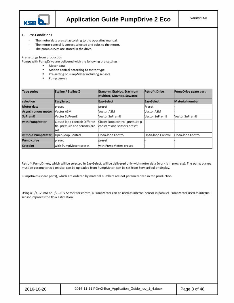
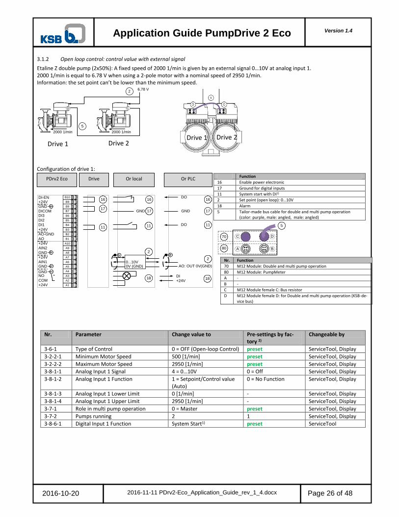
3.1.2 Open loop control: control value with external signal
Etaline Z double pump (2x50%): A fixed speed of 2000 1/min is given by an external signal 0…10V at analog input 1. 2000 1/min is equal to 6.78 V when using a 2-pole motor with a nominal speed of 2950 1/min. Information: the set point can’t be lower than the minimum speed.
6,78 V
2000 1/min
2
2000 1/min
D C
5
Configuration of drive 1:
Nr. Parameter Change value to Pre-settings by fac-tory 2)
Changeable by
3-6-1 Type of Control 0 = OFF (Open-loop Control) preset ServiceTool, Display
3-2-2-1 Minimum Motor Speed 500 [1/min] preset ServiceTool, Display
3-2-2-2 Maximum Motor Speed 2950 [1/min] preset ServiceTool, Display
3-8-1-1 Analog Input 1 Signal 4 = 0…10V 0 = Off ServiceTool, Display
3-8-1-2 Analog Input 1 Function 1 = Setpoint/Control value (Auto)
0 = No Function ServiceTool, Display
3-8-1-3 Analog Input 1 Lower Limit 0 [1/min] - ServiceTool, Display
3-8-1-4 Analog Input 1 Upper Limit 2950 [1/min] - ServiceTool, Display
3-7-1 Role in multi pump operation 0 = Master preset ServiceTool, Display
3-7-2 Pumps running 2 1 ServiceTool, Display
3-8-6-1 Digital Input 1 Function System Start1) preset ServiceTool
Nr. Function
16 Enable power electronic
17 Ground for digital inputs
11 System start with DI1)
2 Set point (open loop): 0…10V
18 Alarm
5 Tailor-made bus cable for double and multi pump operation (color: purple, male: angled, male: angled)
Nr. Function
70 M12 Module: Double and multi pump operation
80 M12 Module: PumpMeter
A -
B -
C M12 Module female C: Bus resistor
D M12 Module female D: for Double and multi pump operation (KSB-de-vice bus)
PDrv2 Eco Or local Or PLC Drive
Drive 1 Drive 2 Drive 1 Drive 2

Version 1.4
Application Guide PumpDrive 2 Eco
2016-10-20 2016-11-11 PDrv2-Eco_Application_Guide_rev_1_4.docx
Page 27 of 48
26
27
11
2
26
27GND
DO
GND
DO
26
27
11
DI-EN+24V
GND
DI3
DI2DI1
+24V
DICOM
AO-GND
AO
AIN2
NO
+24V
GND
COM+24V
B1
B2
B3
B4
B5
B6
B7
B8
B9
B10
A1
A2
A3
A4
A5
A6
A7
A8
A9
A10
GND
GNDAIN1
+24V
0...10V
0V(GND)
2AO: 0...10VAO: OUT 0V(GND)
28+24V
DI28
11
71
81 A B
C D
5
Configuration of drive 2:
Nr. Parameter Change value to Pre-settings by fac-tory 2)
Changeable by
3-6-1 Type of Control 0 = OFF (Open-loop Control) preset ServiceTool, Display
3-2-2-1 Minimum Motor Speed 500 [1/min] preset ServiceTool, Display
3-2-2-2 Maximum Motor Speed 2950 [1/min] preset ServiceTool, Display
3-8-1-1 Analog Input 1 Signal 4 = 0…10V 0 = off ServiceTool, Display
3-8-1-2 Analog Input 1 Function 1 = Setpoint/Control value (Auto)
0 = No Function ServiceTool, Display
3-8-1-3 Analog Input 1 Lower Limit 0 [1/min] - ServiceTool, Display
3-8-1-4 Analog Input 1 Upper Limit 2950 [1/min] - ServiceTool, Display
3-7-1 Role in multi pump operation 0 = Master preset ServiceTool, Display
3-7-2 Pumps running 2 1 ServiceTool, Display
3-8-6-1 Digital Input 1 Function System Start1) preset ServiceTool
1) Digital Input 1 is set as at the factory as system start. If a digital input is set as system start, the parameter 1-3-1 System start is auto-matically without function (see control point concept in operating manual) 2) Pre-settings for completely assembled pump, motor, drive
Nr. Function
26 Enable power electronic
27 Ground for digital inputs
11 System start with DI1)
2 Set point (open loop): 0…10V
28 Alarm
5 Tailor-made bus cable for double and multi pump operation (color: purple, male: angled, male: angled)
Nr. Function
71 M12 Module: Double and multi pump operation
81 M12 Module: PumpMeter
A -
B -
C M12 Module female C: for Double and multi pump operation (KSB-device bus)
D M12 Module female D: Bus resistor
PDrv2 Eco Or local Or PLC Drive

Version 1.4
Application Guide PumpDrive 2 Eco
2016-10-20 2016-11-11 PDrv2-Eco_Application_Guide_rev_1_4.docx
Page 28 of 48
16
17
16
17GND
DO
GND
16
17
DO 1111
DI-EN+24V
GND
DI3
DI2DI1
+24V
DICOM
AO-GND
AO
AIN2
NO
+24V
GND
COM+24V
B1
B2
B3
B4
B5
B6
B7
B8
B9
B10
A1
A2
A3
A4
A5
A6
A7
A8
A9
A10
GND
GNDAIN1
+24V
18+24V
DI18
11
70
80
4
DC
BA
5
3.2 Double pump – closed loop control
3.2.1 Closed loop control non redundant: differential pressure with PumpMeter (Modbus) – typical application
Etaline Z double pump (2x100%): A constant differential pressure of 4 bar is needed. PumpMeter is used as a differential pressure sensor in the measurement range of -1 … 10 bar. PumpMeter is connected by Modbus to the M12 Module of the drive. The set point is given by the display. Pump changeover will take place regularly after 24 hours of operation.
Δp
4
A
D C
5
Configuration of drive 1 (Master):
Nr. Parameter Change value to Pre-settings by fac-tory 2)
Changeable by
3-6-1 Type of Control 3 = Differential Pressure preset ServiceTool, Display
3-11-2-1 Minimum Pressure -1.00 [bar] preset ServiceTool
3-11-2-2 Maximum Pressure 10.00 [bar] preset ServiceTool
3-11-2-3 Pressure Unit bar preset ServiceTool
1-3-2 Setpoint (Closed-loop Control) 4.00 [bar] preset acc. specified Q,H
ServiceTool, Display
3-8-4-1 Function M12 Module Input A 1 = PMtr Suction/Discharge Pressure
preset ServiceTool, Display
3-7-1 Role in multi pump operation 0 = Master preset ServiceTool, Display
3-7-2 Pumps running 1 preset ServiceTool, Display
3-7-4-1 Automatic pump change 1 = operating hours preset ServiceTool, Display
3-7-4-2 Time pump running 24 preset ServiceTool, Display
3-8-6-1 Digital Input 1 Function System Start1) preset ServiceTool
Nr. Function
16 Enable power electronic
17 Ground for digital inputs
11 System start with DI1)
18 Alarm
4 Actual value: tailor-made bus cable for the connection of PumpMeter to the M12 Module (color: black, female: straight, male: angled)
5 Tailor-made bus cable for double and multi pump operation (color: purple, male: angled, male: angled)
Nr. Function
70 M12 Module: Double and multi pump operation
80 M12 Module: PumpMeter
A M12 Module female A: connection PumpMeter (Modbus)
B -
C M12 Module female C: Bus resistor
D M12 Module female D: for Double and multi pump operation (KSB-de-vice bus)
PDrv2 Eco Or local Or PLC Drive
Master Slave Master Slave
Drive 1 (Master) Drive 2 (Slave)

Version 1.4
Application Guide PumpDrive 2 Eco
2016-10-20 2016-11-11 PDrv2-Eco_Application_Guide_rev_1_4.docx
Page 29 of 48
71
81
DC
BA
5
26
27
26
27GND
DO
GND
26
27
DI-EN+24V
GND
DI3
DI2DI1
+24V
DICOM
AO-GND
AO
AIN2
NO
+24V
GND
COM+24V
B1
B2
B3
B4
B5
B6
B7
B8
B9
B10
A1
A2
A3
A4
A5
A6
A7
A8
A9
A10
GND
GNDAIN1
+24V
28+24V
DI28
Configuration of drive 2 (Slave):
Nr. Parameter Change value to Pre-settings by fac-tory 2)
Changeable by
3-7-1 Role in Multiple Pump System
1 = Auxiliary preset ServiceTool, Display
1) Digital Input 1 is set as at the factory as system start. If a digital input is set as system start, the parameter 1-3-1 System start is auto-matically without function (see control point concept in operating manual) 2) Pre-settings for completely assembled pump, motor, drive
Nr. Function
26 Enable power electronic
27 Ground for digital inputs
11 System start with DI1)
28 Alarm
5 Tailor-made bus cable for double and multi pump operation (color: purple, male: angled, male: angled)
Nr. Function
71 M12 Module: Double and multi pump operation
81 M12 Module: PumpMeter
A -
B -
C M12 Module female C: for Double and multi pump operation (KSB-de-vice bus)
D M12 Module female D: Bus resistor
PDrv2 Eco Or local Or PLC Drive

Version 1.4
Application Guide PumpDrive 2 Eco
2016-10-20 2016-11-11 PDrv2-Eco_Application_Guide_rev_1_4.docx
Page 30 of 48
16
17
16
17GND
DO
GND
16
17
DO 1111
DI-EN+24V
GND
DI3
DI2DI1
+24V
DICOM
AO-GND
AO
AIN2
NO
+24V
GND
COM+24V
B1
B2
B3
B4
B5
B6
B7
B8
B9
B10
A1
A2
A3
A4
A5
A6
A7
A8
A9
A10
GND
GNDAIN1
+24V
18+24V
DI18
11
70
80
4
DC
BA
5
6
3.2.2 Closed loop control redundant: differential pressure with PumpMeter (Modbus)
Etaline Z double pump (2x100%): A constant differential pressure of 4 bar is needed. PumpMeter is used as a differential pressure sensor in the measurement range of -1 … 10 bar. PumpMeter is connected by Modbus to the M12 Module of the drive. The sensor signal of PumpMeter is linked by a cross link cable (see accessories) from drive to drive. The AuxMaster can take over control if the Master fails. The set point is given by the display. Pump changeover will take place regularly after 24 hours of operation.
D C
Δp
2
5
Configuration of drive 1 (Master):
Nr. Parameter Change value to Pre-settings by factory 2) Changeable by
3-6-1 Type of Control 3 = Differential Pressure preset ServiceTool, Display
3-11-2-1 Minimum Pressure -1.00 [bar] Preset ServiceTool
3-11-2-2 Maximum Pressure 10.00 [bar] Preset ServiceTool
3-11-2-3 Pressure Unit bar Preset ServiceTool
1-3-2 Setpoint (Closed-loop Control) 4.00 [bar] Acc. specified Q,H preset ServiceTool, Display
3-8-4-1 Function M12 Module Input A 1 = PMtr Suction/Dis-charge Pressure
Preset ServiceTool, Display
3-13-5 PumpMeter Master/Slave Master Preset for Etaline Z ServiceTool
3-7-1 Role in multi pump operation 0 = Master Preset ServiceTool, Display
3-7-2 Pumps running 1 Preset ServiceTool, Display
3-7-4-1 Automatic pump change 1 = Operating hours Preset ServiceTool, Display
3-7-4-2 Time pump running 24 Preset ServiceTool, Display
3-8-6-1 Digital Input 1 Function System Start1) Preset ServiceTool
Nr. Function
16 Enable power electronic
17 Ground for digital inputs
11 System start with DI1)
18 Alarm
4 Actual value: tailor-made bus cable for the connection of PumpMeter to the M12 Module (color: black, female: straight, male: angled)
5 Tailor-made bus cable for double and multi pump operation (color: pur-ple, male: angled, male: angled)
6 Actual value: tailor-made cross link bus cable for the redundant connec-tion of PumpMeter (color: black, female: angled, male: angled)
Nr. Function
70 M12 Module: Double and multi pump operation
80 M12 Module: PumpMeter
A M12 Module female A: connection PumpMeter (Modbus)
B M12 Module female B: cross link bus cable PumpMeter (Modbus)
C M12 Module female C: Bus resistor
D M12 Module female D: for Double and multi pump operation (KSB-de-vice bus)
PDrv2 Eco Or local Or PLC Drive
Master Aux Master
Modbus Master!
Special Firmware Modbus Master in PumpMeter is needed. In case of Eta-line Z the special firm-ware is programmed in factory
Drive 1 (Master) Drive 2 (Aux Master)

Version 1.4
Application Guide PumpDrive 2 Eco
2016-10-20 2016-11-11 PDrv2-Eco_Application_Guide_rev_1_4.docx
Page 31 of 48
26
27
11
26
27GND
DO
GND
26
27
DO 11
DI-EN+24V
GND
DI3
DI2DI1
+24V
DICOM
AO-GND
AO
AIN2
NO
+24V
GND
COM+24V
B1
B2
B3
B4
B5
B6
B7
B8
B9
B10
A1
A2
A3
A4
A5
A6
A7
A8
A9
A10
GND
GNDAIN1
+24V
28+24V
DI28
11
71
81
DC
BA
6
5
Configuration of drive 2 (AuxMaster):
Nr. Parameter Change value to Pre-settings by factory 2) Changeable by
3-6-1 Type of Control 3 = Differential Pressure Preset ServiceTool, Display
3-11-2-1 Minimum Pressure -1.00 [bar] Preset ServiceTool
3-11-2-2 Maximum Pressure 10.00 [bar] Preset ServiceTool
3-11-2-3 Pressure Unit bar Preset ServiceTool
1-3-2 Setpoint (Closed-loop Control) 4.00 [bar] preset acc. specified Q,H ServiceTool, Display
3-8-4-1 Function M12 Module Input A 1 = PMtr Suction/Dis-charge Pressure
Preset ServiceTool, Display
3-13-5 PumpMeter Master/Slave Master Preset for Etaline Z ServiceTool
3-7-1 Role in multi pump operation 0 = master Slave when Etaline Z ServiceTool, Display
3-7-2 Pumps running 1 Preset ServiceTool, Display
3-7-4-1 Automatic pump change 1 = Operating hours Preset ServiceTool, Display
3-7-4-2 Time pump running 24 Preset ServiceTool, Display
3-8-6-1 Digital Input 1 Function System Start1) Preset ServiceTool
1) Digital Input 1 is set as at the factory as system start. If a digital input is set as system start, the parameter 1-3-1 System start is auto-matically without function (see control point concept in operating manual) 2) Pre-settings for completely assembled pump, motor, drive and PumpMeter
Nr. Function
26 Enable power electronic
27 Ground for digital inputs
11 System start with DI1)
28 Alarm
5 Tailor-made bus cable for double and multi pump operation (color: pur-ple, male: angled, male: angled)
6 Actual value: tailor-made cross link bus cable for the redundant connec-tion of PumpMeter (color: black, female: angled, male: angled)
Nr. Function
71 M12 Module: Double and multi pump operation
81 M12 Module: PumpMeter
A M12 Module female A: connection PumpMeter (Modbus)
B M12 Module female B: cross link bus cable PumpMeter (Modbus)
C M12 Module female C: Bus resistor
D M12 Module female D: for Double and multi pump operation (KSB-de-vice bus)
PDrv2 Eco Or local Or PLC Drive

Version 1.4
Application Guide PumpDrive 2 Eco
2016-10-20 2016-11-11 PDrv2-Eco_Application_Guide_rev_1_4.docx
Page 32 of 48
A A
D C
4 4
5
6
77
6
D
2
p
2
2
DC
p 2 2
5
A A
3.2.3 Closed loop control redundant: Discharge pressure with sensor 4…20mA and PumpMeter each pump
Etaline / Etabloc (2x100%): In a multi pump system with three pumps a constant pressure of 4bar is needed. The 4…20mA pressure sen-sor with a measurement range of 0-6 bar placed in the manifold is connected in parallel to each analog input 2 of Master and AuxMas-ter1. The AuxMaster can take over control if the Master fails. When connecting a 4…20mA sensor in parallel to all drives the 4…20mA current signal must be converted to 2…10V voltage signal: therefore the DIP switch of the analog input 2 of the Master must be set to “ON”3). Each pump uses PumpMeter as an internal sensor -1 to 6bar, which is not used for the control. The set point is given by the dis-play.
Nr. Function
2 Actual value: pressure sensor 4…20mA redundant
4 Tailor-made bus cable for the connection of PumpMeter to the M12 Module (color: black, female: straight, male: angled)
5 Tailor-made bus cable for double and multi pump operation (color: purple, male: angled, male: angled)
6 Sensor PumpMeter suction side
7 Sensor PumpMeter pressure side
A M12 12 Module female A: connection PumpMeter (Modbus)
B -
C M12 Module female C: for Double and multi pump operation (KSB-de-vice bus) or Bus resistor
D M12 Module female D: for Double and multi pump operation (KSB-de-vice bus) or Bus resistor
Drive 1 (Master) Drive 2 (AuxMaster)
Master Aux Master

Version 1.4
Application Guide PumpDrive 2 Eco
2016-10-20 2016-11-11 PDrv2-Eco_Application_Guide_rev_1_4.docx
Page 33 of 48
70
80
4
DC
BA
5
16
17
DO
GND
16
17
DO 1111
16
17GND
DI-EN+24V
GND
DI3
DI2DI1
+24V
DICOM
AO-GND
AO
AIN2
NO
+24V
GND
COM+24V
B1
B2
B3
B4
B5
B6
B7
B8
B9
B10
A1
A2
A3
A4
A5
A6
A7
A8
A9
A10
GND
GNDAIN1
+24V
2
18+24V
DI18
Configuration of Drive 1 (Master):
Nr. Parameter Change value to Pre-settings by factory 2)
3-6-1 Type of Control 1= Discharge Pressure 3 = Differential pressure
3-11-2-1 Minimum Pressure 0.00 [bar] -1.00 [bar]
3-11-2-2 Maximum Pressure 6.00 [bar] 6.00 [bar]
3-11-2-3 Pressure Unit bar Preset
1-3-2 Setpoint (Closed-loop Control) 4.00 [bar] 0,00 [bar]
3-8-2-1 Analog Input 2 Signal 2 = 2…10V3) 0 = OFF
3-8-2-2 Analog Input 2 Function 5 = Discharge Pressure 0 = No Function
3-8-2-3 Analog Input 2 Lower Limit 0.00 [bar] -
3-8-2-4 Analog Input 2 Upper Limit 6.00 [bar] -
3-8-4-1 Function M12 Module Input A 2 = PMtr Internal Suction/Discharge Pres-sure4)
1 = PMtr Suction/Discharge Pres-sure
3-7-1 Role in Multiple Pump System 0 = Master control Preset
3-7-2 Maximum Number of Pumps Running 1 1
3-7-4-1 Automatic Pump Changeover 1 = Runtime Preset
3-7-4-2 Runtime Prior to Pump Changeover 24 Preset
3-8-6-1 Digital Input 1 Function System Start1) Preset
Nr. Function
16 Enable power electronic
17 Ground for digital inputs
11 System start with DI1)
2 Actual value: pressure sensor 4…20mA
18 Alarm
4 Tailor-made bus cable for the connection of PumpMeter to the M12 Module (color: black, female: straight, male: angled)
5 Tailor-made bus cable for double and multi pump operation (color: purple, male: angled, male: angled)
Nr. Function
70 M12 Module: Double and multi pump operation
80 M12 Module: PumpMeter
A M12 12 Module female A: connection PumpMeter (Modbus)
B -
C M12 Module female C: Bus resistor
D M12 Module female D: for Double and multi pump operation (KSB-de-vice bus)
Master Or local Or PLC drive O
N
O
N

Version 1.4
Application Guide PumpDrive 2 Eco
2016-10-20 2016-11-11 PDrv2-Eco_Application_Guide_rev_1_4.docx
Page 34 of 48
72
82 A B
C D
5
4
26
27
DO
GND
26
27
DO 1111
26
27GND
2
DI-EN+24V
GND
DI3
DI2DI1
+24V
DICOM
AO-GND
AO
AIN2
NO
+24V
GND
COM+24V
B1
B2
B3
B4
B5
B6
B7
B8
B9
B10
A1
A2
A3
A4
A5
A6
A7
A8
A9
A10
GND
GNDAIN1
+24V
28+24V
DI28
Configuration Drive 2 (AuxMaster 1):
Nr. Parameter Change value to Pre-settings by factory 2)
3-6-1 Type of Control 1= Discharge Pressure 3 = Differential pressure
3-11-2-1 Minimum Pressure 0.00 [bar] -1.00 [bar]
3-11-2-2 Maximum Pressure 6.00 [bar] 6.00 [bar]
3-11-2-3 Pressure Unit bar Preset
1-3-2 Setpoint (Closed-loop Control) 4.00 [bar] 0,00 [bar]
3-8-2-1 Analog Input 2 Signal 2 = 2…10V3) 0 = OFF
3-8-2-2 Analog Input 2 Function 5 = Discharge Pressure 0 = No Function
3-8-2-3 Analog Input 2 Lower Limit 0.00 [bar] -
3-8-2-4 Analog Input 2 Upper Limit 6.00 [bar] -
3-8-4-1 Function M12 Module Input A 2 = PMtr Internal Suction/Dis-charge Pressure4)
1 = PMtr Suction/Discharge Pressure
3-7-1 Role in Multiple Pump System 0 = Master control Preset
3-7-2 Maximum Number of Pumps Running 1 1
3-7-4-1 Automatic Pump Changeover 1 = Runtime Preset
3-7-4-2 Runtime Prior to Pump Changeover 24 Preset
3-8-6-1 Digital Input 1 Function System Start1) Preset
1) Digital Input 1 is set as at the factory as system start. If a digital input is set as system start, the parameter 1-3-1 System start is auto-matically without function (see control point concept in operating manual) 2) Pre-settings for completely assembled pump, motor, drive 3) On all drives will be the 4…20mA signal converted to 2…10V signal, if the DIP switch in the Master is set to „ON“ 4) If PumpMeter is only used as an internal measured variable at input A of the M12 module (via Modbus) and not for control, the Func-tion M12 Module Input A parameter (3-8-4-1) must be set to PMtr Internal Suction/Discharge Pressure.
Nr. Function
26 Enable power electronic
27 Ground for digital inputs
11 System start with DI1)
2 Actual value: pressure sensor 4…20mA
28 Alarm
4 Tailor-made bus cable for the connection of PumpMeter to the M12 Module (color: black, female: straight, male: angled)
5 Tailor-made bus cable for double and multi pump operation (color: purple, male: angled, male: angled)
Nr. Function
72 M12 Module: Double and multi pump operation
82 M12 Module: PumpMeter
A M12 12 Module female A: connection PumpMeter (Modbus)
B -
C M12 Module female C: for Double and multi pump operation (KSB-de-vice bus)
D M12 Module female D: Bus resistor
O
N
AuxMaster 2 Oder vor Ort Oder SPS Im Gerät
O
N

Version 1.4
Application Guide PumpDrive 2 Eco
2016-10-20 2016-11-11 PDrv2-Eco_Application_Guide_rev_1_4.docx
Page 35 of 48
DC
p 2 3
5
A AB
A A
D C
5
6
D
2
p
B
3.2.4 Closed loop control redundant: Discharge pressure with pressure sensor 4…20mA via M12
Etaline / Etabloc (2x100%): In a multi pump system with three pumps a constant pressure of 4bar is needed. The 4…20mA pressure sen-sor with a measurement range of 0-6 bar placed in the manifold is connected in parallel to each analog input 2 of Master and AuxMas-ter1. The AuxMaster can take over control if the Master fails. When connecting a 4…20mA sensor in parallel to all drives the 4…20mA current signal must be converted to 2…10V voltage signal: therefore the DIP switch of the analog input 2 of the Master must be set to “ON”3). The set point is given by the display. After 24 h the pumps switch automatically. Assignment M12 plug pressure sensor:
Nr. Function
2 Actual value: pressure sensor 4…20mA redundant
5 Tailor-made bus cable for double and multi pump operation (color: purple, male: angled, male: angled)
6 tailor-made cross link bus cable for the redundant connection of the pressure sensor (color: black, female: angled, male: angled
A M12 Module female A: connection pressure sensor
B M12 Module female B: connection cross link bus cable for the redun-dant connection
C M12 Module female C: for Double and multi pump operation (KSB-de-vice bus) or Bus resistor
D M12 Module female D: for Double and multi pump operation (KSB-de-vice bus) or Bus resistor
Drive 1 (Master) Drive 2 (AuxMaster)
Master Aux Master
5
3 4
12
+24 V
GND /
Schirm
N
Signal

Version 1.4
Application Guide PumpDrive 2 Eco
2016-10-20 2016-11-11 PDrv2-Eco_Application_Guide_rev_1_4.docx
Page 36 of 48
16
17
DO
GND
16
17
DO 1111
16
17GND
DI-EN+24V
GND
DI3
DI2DI1
+24V
DICOM
AO-GND
AO
AIN2
NO
+24V
GND
COM+24V
B1
B2
B3
B4
B5
B6
B7
B8
B9
B10
A1
A2
A3
A4
A5
A6
A7
A8
A9
A10
GND
GNDAIN1
+24V
18+24V
DI18
70
80
4
DC
BA
5
6
Configuration of Drive 1 (Master):
Nr. Parameter Change value to Pre-settings by factory 2)
Adjustable via
3-6-1 Type of Control 1= Discharge Pressure 3 = Differential pressure ServiceTool, HMI
3-11-2-1 Minimum Pressure 0.00 [bar] -1.00 [bar] ServiceTool, HMI 3-11-2-2 Maximum Pressure 6.00 [bar] 999,99 [bar] ServiceTool, HMI 3-11-2-3 Pressure Unit bar Preset ServiceTool
1-3-2 Setpoint (Closed-loop Control) 4.00 [bar] 0,00 [bar] ServiceTool, HMI 3-8-2-4 Analog Input 2 Upper Limit 6.00 [bar] - ServiceTool, HMI 3-8-4-1 Function M12 Module Input A 4 = Discharge Pressure 0 = OFF ServiceTool, HMI
3-8-4-2 Lower Limit M12 Module Input A 0.00 [bar] - ServiceTool, HMI
3-8-4-3 Upper Limit M12 Module Input A 6.00 [bar] - ServiceTool, HMI
3-7-1 Role in Multiple Pump System 0 = Master control Preset ServiceTool, HMI 3-7-2 Maximum Number of Pumps Running 1 Preset ServiceTool, HMI 3-7-4-1 Automatic Pump Changeover 1 = Runtime Preset ServiceTool
3-7-4-2 Runtime Prior to Pump Changeover 24 Preset ServiceTool, HMI
3-8-6-1 Digital Input 1 Function System Start1) Preset ServiceTool
DIP Switch M12 Module Drive 1 (Picture shows the preset DIP switch)
Nr. Function
16 Enable power electronic
17 Ground for digital inputs
11 System start with DI1)
18 Alarm
4 Tailor-made cable for the connection of pressure sensor to the M12 Module
5 Tailor-made bus cable for double and multi pump operation (color: purple, male: angled, male: angled)
6 tailor-made cross link bus cable for the redundant connection of the pressure sensor (color: black, female: angled, male: angled)
Nr. Function
70 M12 Module: Double and multi pump operation
80 M12 Module: PumpMeter / Pressure Sensor
A M12 Module female A: connection pressure sensor
B M12 Module female B: cross link bus cable for the redundant connec-tion of the pressure sensor
B M12 Module female B: cross link cable is not necessary if there is an additional sensor connected to the Aux Master.
C M12 Module female C: Bus resistor
D M12 Module female D: for Double and multi pump operation (KSB-de-vice bus)
Master Or local Or PLC drive

Version 1.4
Application Guide PumpDrive 2 Eco
2016-10-20 2016-11-11 PDrv2-Eco_Application_Guide_rev_1_4.docx
Page 37 of 48
72
82 A B
C D
5
4
26
27
DO
GND
26
27
DO 1111
26
27GND
DI-EN+24V
GND
DI3
DI2DI1
+24V
DICOM
AO-GND
AO
AIN2
NO
+24V
GND
COM+24V
B1
B2
B3
B4
B5
B6
B7
B8
B9
B10
A1
A2
A3
A4
A5
A6
A7
A8
A9
A10
GND
GNDAIN1
+24V
28+24V
DI28
Configuration Drive 2 (AuxMaster 1):
Nr. Parameter Change value to Pre-settings by factory 2) Adjustable via
3-7-1 Role in Multiple Pump System 0 = Master control Preset ServiceTool, HMI
3-7-2 Maximum Number of Pumps Running 1 1 ServiceTool, HMI 3-7-4-1 Automatic Pump Changeover 1 = Runtime Preset ServiceTool, HMI 3-7-4-2 Runtime Prior to Pump Changeover 24 Preset ServiceTool, HMI
1) Digital Input 1 is set as at the factory as system start. If a digital input is set as system start, the parameter 1-3-1 System start is auto-matically without function (see control point concept in operating manual) 2) Pre-settings for completely assembled pump, motor, drive 3) On all drives will be the 4…20mA signal converted to 2…10V signal, if the DIP switch in the Master is set to „ON“ 4) If there is a cross link cable for the redundant connection of the pressure sensor, only one switch CURR-IN should be set to ON. So the 4…20mA signal will be converted to 2…10V signal. 5) If an additional sensor is connected to the AUX master the DIP switch should be ON. DIP Switch M12 Module Drive 2
Nr. Function
26 Enable power electronic
27 Ground for digital inputs
11 System start with DI1)
28 Alarm
4 Tailor-made cable for the connection of pressure sensor to the M12 Module
5 Tailor-made bus cable for double and multi pump operation (color: purple, male: angled, male: angled)
6 tailor-made cross link bus cable for the redundant connection of the pressure sensor (color: black, female: angled, male: angled)
Nr. Function
72 M12 Module: Double and multi pump operation
82 M12 Module: PumpMeter / Pressure Sensor
A M12 Module female A: connection pressure sensor
B -
C M12 Module female D: for Double and multi pump operation (KSB-de-vice bus)
D M12 Module female C: Bus resistor
AuxMaster 2 Oder vor Ort Oder SPS Im Gerät

Version 1.4
Application Guide PumpDrive 2 Eco
2016-10-20 2016-11-11 PDrv2-Eco_Application_Guide_rev_1_4.docx
Page 38 of 48
16
17
DO
GND
16
17
16
17GND
DI-EN+24V
GND
DI3
DI2DI1
+24V
DICOM
AO-GND
AO
AIN2
NO
+24V
GND
COM+24V
B1
B2
B3
B4
B5
B6
B7
B8
B9
B10
A1
A2
A3
A4
A5
A6
A7
A8
A9
A10
GND
GNDAIN1
+24V
18+24V
DI18
11DO
1111 70
80
4
DC
BA
4. Pump functionality
4.1 Closed loop control
4.1.1 Closed loop control: dynamic differential pressure set point compensation based on flow rate estimation
A constant differential pressure of 4 bar is needed. PumpMeter is used as a differential pressure sensor in the measurement range of -1 … 10 bar. PumpMeter is connected by Modbus to the M12 Module of the drive. The set point is given by the display. For the optimal energy saving the “dynamic differential pressure set point compensation based on flow rate estimation” is activated. The nominal flow is 80 m³/h. The pipe friction losses are roundabout 1 bar. All parameters needed for the flow estimation like pipe diameters are preset indi-vidually for each pump size by the pump production when ordering a completely assembled pump, motor, drive.
Nr. Parameter Change value to Pre-settings by fac-tory 2)
3-6-1 Type of Control 3 = Differential Pressure preset - see chapter 1
ServiceTool, Display
3-11-2-1 Minimum Pressure -1.00 [bar] Preset ServiceTool
3-11-2-2 Maximum Pressure 10.00 [bar] Preset ServiceTool
3-11-2-3 Pressure Unit bar Preset ServiceTool
3-11-3-1 Minimum Flow rate 0.00 [m³/h] Preset ServiceTool
3-11-3-2 Maximum Flow rate 100.00 [m³/h] 9999.99 [m³/h] ServiceTool
3-11-3-3 Unit Flow rate m³/h Preset ServiceTool
1-3-2 Setpoint (Closed-loop Control) 4.00 [bar] preset acc. specified Q,H
ServiceTool, Display
3-8-4-1 Function M12 Module Input A 1 = PMtr Suction/ Dis-charge Pressure
Preset ServiceTool, Display
3-9-8-1 Flow Rate Estimation 1 = On Preset ServiceTool, Display
3-5-2-1 Pipe Diameter Suction Pressure Measuring Point
30 mm Preset ServiceTool
Nr. Function
16 Enable power electronic
17 Ground for digital inputs
11 System start with DI1)
18 Alarm
4 Actual value: tailor-made bus cable for the connection of PumpMeter to the M12 Module (color: black, female: straight, male: angled)
Nr. Function
70 M12 Module: Double and multi pump operation
80 M12 Module: PumpMeter
A M12 Module female A: connection PumpMeter (Modbus)
B -
C -
D -
1 bar
4 bar
80 m³/h
PDrv 2 Eco Or local Or PLC Drive
?pA
4
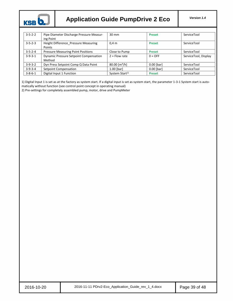
Version 1.4
Application Guide PumpDrive 2 Eco
2016-10-20 2016-11-11 PDrv2-Eco_Application_Guide_rev_1_4.docx
Page 39 of 48
3-5-2-2 Pipe Diameter Discharge Pressure Measur-ing Point
30 mm Preset ServiceTool
3-5-2-3 Height Difference_Pressure Measuring Points
0,4 m Preset ServiceTool
3-5-2-4 Pressure Measuring Point Positions Close to Pump Preset ServiceTool
3-9-3-1 Dynamic Pressure Setpoint Compensation Method
2 = Flow rate 0 = OFF ServiceTool, Display
3-9-3-2 Dyn Press Setpoint Comp Q Data Point 80.00 [m³/h] 0.00 [bar] ServiceTool
3-9-3-4 Setpoint Compensation 1.00 [bar] 0.00 [bar] ServiceTool
3-8-6-1 Digital Input 1 Function System Start1) Preset ServiceTool
1) Digital Input 1 is set as at the factory as system start. If a digital input is set as system start, the parameter 1-3-1 System start is auto-matically without function (see control point concept in operating manual) 2) Pre-settings for completely assembled pump, motor, drive and PumpMeter

Version 1.4
Application Guide PumpDrive 2 Eco
2016-10-20 2016-11-11 PDrv2-Eco_Application_Guide_rev_1_4.docx
Page 40 of 48
16
17
DO
GND
16
17
16
17GND
DI-EN+24V
GND
DI3
DI2DI1
+24V
DICOM
AO-GND
AO
AIN2
NO
+24V
GND
COM+24V
B1
B2
B3
B4
B5
B6
B7
B8
B9
B10
A1
A2
A3
A4
A5
A6
A7
A8
A9
A10
GND
GNDAIN1
+24V
18+24V
DI18
11DO
1111
2
4.1.2 Closed loop control: dynamic differential pressure set point compensation based on speed
A constant differential pressure of 4 bar is needed. The 4…20mA differential pressure sensor with a measurement range of 0-6 bar is connected to analog input 2. The set point is given by the display. If neither the measured nor estimated flow rate is available, dynamic pressure setpoint compensation can be realized based on speed. This is only possible for closed hydraulic circuits, however. The nominal flow is 80 m³/h. The pipe friction losses are roundabout 1 bar. All parameters needed for the flow estimation like pipe diameters are pre-set individually for each pump size by the pump production when ordering a completely assembled pump, motor, drive. Δp
2
Nr. Parameter Change value to Pre-settings by factory 2)
Changeable by
3-6-1 Type of Control 3 = Differential Pressure 0 = OFF (Open-loop Control)
ServiceTool, Display
3-11-2-1 Minimum Pressure 0.00 [bar] -1,00 [bar] ServiceTool
3-11-2-2 Maximum Pressure 6.00 [bar] 999,99 [bar] ServiceTool
3-11-2-3 Pressure Unit bar Preset ServiceTool
3-2-2-1 Minimum Motor Speed 500 [1/min] Preset ServiceTool, Display
3-2-2-2 Maximum Motor Speed 2950 [1/min] Preset ServiceTool, Display
1-3-2 Setpoint (Closed-loop Control) 4.00 [bar] 0,00 [bar] ServiceTool, Display
3-8-2-1 Analog Input 2 Signal 1 = 4…20mA 0 = Off ServiceTool, Display
3-8-2-2 Analog Input 2 Function 6 = Differential Pressure 0 = No Function ServiceTool, Display
3-8-2-3 Analog Input 2 Lower Limit 0.00 [bar] - ServiceTool, Display
3-8-2-4 Analog Input 2 Upper Limit 6.00 [bar] - ServiceTool, Display
3-9-3-1 Dynamic Pressure Setpoint Compen-sation Method
1 = speed 0 = Off ServiceTool, Display
3-9-3-3 Dyn Press Setpoint Comp n Data Point
100 [%] 0 [%] ServiceTool
3-9-3-4 Setpoint Compensation 1.00 [bar] 0.00 [bar] ServiceTool
3-8-6-1 Digital Input 1 Function System Start1) Preset ServiceTool
1) Digital Input 1 is set as at the factory as system start. If a digital input is set as system start, the parameter 1-3-1 System start is auto-matically without function (see control point concept in operating manual) 2) Pre-settings for completely assembled pump, motor, drive
Nr. Function
16 Enable power electronic
17 Ground for digital inputs
11 System start with DI1)
2 Actual value: pressure sensor 4…20mA
18 Alarm
1 bar
4 bar
80 m³/h
PDrv 2 Eco
Or local Or PLC Drive

Version 1.4
Application Guide PumpDrive 2 Eco
2016-10-20 2016-11-11 PDrv2-Eco_Application_Guide_rev_1_4.docx
Page 41 of 48
16
17
14
1312
14
DO 13
DO 12
DO
GND
16
17
16
17GND
DO
DI-EN+24V
GND
DI3
DI2DI1
+24V
DICOM
AO-GND
AO
AIN2
NO
+24V
GND
COM+24V
B1
B2
B3
B4
B5
B6
B7
B8
B9
B10
A1
A2
A3
A4
A5
A6
A7
A8
A9
A10
GND
GNDAIN1
+24V
18+24V
DI18
AO: 4...20mA
AO: GND19
4.1.3 Open loop control: 1 fix speed selected by digital switches or variable speed via analog signal
A fixed speed of 2000 1/min should be set on the display. The nominal speed of the 2 pole motor is 2950 1/min. 1 additional fixed speeds and OFF should be selectable by local digital switches: Attention: The drive must now always be turned on via the digital inputs by selecting auto zero or Man The keyboard will be blocked when you select this function
Info: by selecting a fixed speed the drive changes to manual operation. The Auto button at the display is then out of function (see also control point concept
14
13
12
Nr. Parameter Change value to Pre-settings by factory 2) Changeable by
3-6-1 Type of Control OFF (Open-loop Control) Preset ServiceTool, Display
3-2-2-1 Minimum Motor Speed 500 [1/min] Preset ServiceTool, Display 3-2-2-2 Maximum Motor Speed 2950 [1/min] Preset ServiceTool, Display 1-3-3 Control Value (Open-loop Control) 2000 [1/min] 500 [1/min] ServiceTool, Display 3-6-5-1 Fixed speed 1 2950 [1/min] 500 [1/min] ServiceTool 3-8-1-2 Analog Input 1 Function 3 = Control Point Hand 0 = No Function ServiceTool 3-8-1-3 Analog Input 1 Lower Limit 0 [1/min] - ServiceTool 3-8-1-4 Analog Input 1 Upper Limit 2950 [1/min] - ServiceTool 3-8-6-1 Digital Input 1 Function System Start1) Preset ServiceTool 3-8-6-2 Digital Input 2 Function Control Digital Bit 0 Reset Messages ServiceTool 3-8-6-3 Digital Input 3 Function Control Digital Bit 1 No Function ServiceTool
1) Digital Input 1 is set as at the factory as system start. If a digital input is set as system start, the parameter 1-3-1 System start is auto-matically without function (see control point concept in operating manual) 2) Pre-settings for completely assembled pump, motor, drive
DI 1 Automatic Run DI 2: Control Digital Bit 0
DI 3: Control Digital Bit 1
All DI on 0 Off 0 0 0
Automatic only Bit 0 DI 2 on 1 Automatic 0 1 0
Automatic Start Bit 0 DI 2 on 1 and DI 1 on f 1 Automatic Start System 1 1 0
Hand variable speed only Bit 1 DI 3 on 1 Hand (variable speed) 0 0 1
Fix speed e.g. 2950 1/min DI 2 + 3 Bit 0 and 1 on 1 Hand (fix speed 1) 0 1 1
Nr. Function
16 Enable power electronic
17 Ground for digital inputs
14 Digital control Bit 1 hand variable speed
13 Digital control Bit 0 Automatic
12 System start with DI1)
18 Alarm
19 Hand variable speed Signal 0/4 to 10/20 V/mA
PDrv 2 Eco
Or local Or PLC drive

Version 1.4
Application Guide PumpDrive 2 Eco
2016-10-20 2016-11-11 PDrv2-Eco_Application_Guide_rev_1_4.docx
Page 42 of 48
16
17
DO
GND
16
17
16
17GND
DI-EN+24V
GND
DI3
DI2DI1
+24V
DICOM
AO-GND
AO
AIN2
NO
+24V
GND
COM+24V
B1
B2
B3
B4
B5
B6
B7
B8
B9
B10
A1
A2
A3
A4
A5
A6
A7
A8
A9
A10
GND
GNDAIN1
+24V
18+24V
DI18
11DO 11
11 70
80
4
DC
BA
4.1.4 Closed loop control: sleep Mode
A constant differential pressure of 4 bar is needed. PumpMeter is used as a differential pressure sensor in the measurement range of -1 … 10 bar. PumpMeter is connected by Modbus to the M12 Module of the drive. The set point is given by the display. The frequency in-verter stops the pump without setpoint increase in the case of low flow rates, i.e. when the low flow limit or stop speed is reached: Sleep mode without setpoint increase. Sleep mode is only active in the automatic operation. Δp
Nr. Parameter Change value to Pre-settings by fac-tory 2)
Changeable by
3-6-1 Type of Control 3 = Differential Pressure preset - see chapter 1 ServiceTool, Display
3-2-2-1 Minimum Motor Speed 500 [1/min] Preset ServiceTool, Display
3-2-2-2 Maximum Motor Speed 2950 [1/min] Preset ServiceTool, Display
3-11-2-1 Minimum Pressure -1.00 [bar] Preset ServiceTool
3-11-2-2 Maximum Pressure 10.00 [bar] Preset ServiceTool
3-11-2-3 Pressure Unit bar Preset ServiceTool
1-3-2 Setpoint (Closed-loop Control) 4.00 [bar] preset acc. specified Q,H
ServiceTool, Display
3-8-4-1 Function M12 Module Input A 1 = PMtr Suction/Discharge Pressure
Preset ServiceTool, Display
3-9-4-1 Sleep Mode 1 = ON 0 = OFF ServiceTool, Display
3-9-4-2 Setpoint Increase 0.00 [bar] Preset ServiceTool
3-9-4-3 Monitoring Period 30.0 [s] Preset ServiceTool
3-9-4-4 Duration of Setpoint Increase 100.0 [s] Preset ServiceTool
3-9-4-5 Permissible Deviation 1.00 [bar] Preset ServiceTool
3-9-4-6 Minimum Runtime 60.0 [s] Preset ServiceTool
3-9-4-7 Ramp-up Time for Setpoint Increase 30.0 [s] Preset ServiceTool
3-9-4-8 Stop Speed 500 [1/min] Preset ServiceTool
3-8-6-1 Digital Input 1 Function System Start1) Preset ServiceTool
1) Digital Input 1 is set as at the factory as system start. If a digital input is set as system start, the parameter 1-3-1 System start is auto-matically without function (see control point concept in operating manual) 2) Pre-settings for completely assembled pump, motor, drive and PumpMeter
Nr. Function
16 Enable power electronic
17 Ground for digital inputs
11 System start with DI1)
18 Alarm
4 Actual value: tailor-made bus cable for the connection of PumpMeter to the M12 Module (color: black, female: straight, male: angled)
Nr. Function
70 M12 Module: Double and multi pump operation
80 M12 Module: PumpMeter
A M12 Module female A: connection PumpMeter (Modbus)
B -
C -
D -
PDrv 2 Eco
Or local Or PLC Drive

Version 1.4
Application Guide PumpDrive 2 Eco
2016-10-20 2016-11-11 PDrv2-Eco_Application_Guide_rev_1_4.docx
Page 43 of 48
4 A
60
5
3 4
12
5
4 3
21
+24 V
0 V
D+
M N
D-
1 2 3 4 51 2 3 4 5
+24 V
D+
D-
0 V
NM
60
5150
AEXT
5. M12 Cable
5.1 Bus cable for connecting PumpMeter to the M12-Module
Tailor-made cable
Nr. function length Mat.-Nr.
4 tailor-made bus cable for the connection of PumpMeter to the M12 Module (color: black, female: straight, male: angled)
1 m 01533775
2 m 01533776
3 m 01533777
5 m 01533778
10 m 01670718
20 m 01670719
Self-made bus cable for the connection of PumpMeter to the M12 Module, Modbus screened:
Nr. Function length Mat.-Nr.
50 PumpMeter Connector EXT
51 PumpDrive 2 M12 Module – Connector A
60 CAN-Bus Cable, also for Modbus, cut to length, screened, twisted pair, cable 2 x 2 x 0,22 mm²
1 m 01111184
5 m 01304511
10 m 01304512
20 m 01304513
M M12 female, A-coded, 5 poles (Binder Connector Type: 99 1436 814 05)
-
N M12 male, A-coded, 5 poles 01523004

Version 1.4
Application Guide PumpDrive 2 Eco
2016-10-20 2016-11-11 PDrv2-Eco_Application_Guide_rev_1_4.docx
Page 44 of 48
5
D C
61
1 2 3 4 5 1 2 3 4 5
Screen
CAN L
CAN H
M N
61
51 52
CAN GND
CD
5
3 4
12
5
3 4
12Screen
CAN L
CAN GND
CAN H
M N
5.2 Bus cable for Double- and Multi Pump Operation
Tailor-made cable
Nr. function length Mat.-Nr.
5 Tailor-made bus cable for double and multi pump operation (color: purple, male: angled, male: angled)
1 m 01533747
2 m 01533748
3 m 01533749
5 m 01651182
10 m 01651183
20 m 01651184
Self-made bus cable for the connection for double and multi pump operation:
Nr. function length Mat.-Nr.
51 PumpDrive 2 (Drive 1) with M12 Module – Connector D
52 PumpDrive 2 (Drive 2) with M12 Module – Connector C
61 CAN-Bus cable cut to length, screened, twisted pair, cable 2 x 2 x 0,22 mm²
1 m 01111184
5 m 01304511
10 m 01304512
20 m 01304513
M, N M12 male, A-coded, 5 poles 01523004

Version 1.4
Application Guide PumpDrive 2 Eco
2016-10-20 2016-11-11 PDrv2-Eco_Application_Guide_rev_1_4.docx
Page 45 of 48
6
B
A
62
1 2 3 4 5 1 2 3 4 5
24 V
0 V
D -
M N
62
51 52
D +
AB
5
3 4
12
5
3 4
12
24 V
0 V
D +
D -
M N
5.3 Crosslink cable
Tailor-made cable:
Nr. function length Mat.-Nr.
6 tailor-made cross link bus cable for the redundant connection of PumpMeter (color: black, female: angled, male: angled)
1 m 01533769
2 m 01533770
3 m 01533771
5 m 01533772
10 m 01533773
20 m 01533774
Self-made bus cable for the connection for the redundant connection of PumpMeter:
Nr. function length Mat.-Nr.
51 PumpDrive 2 (Drive 1) with M12 Module – Connector B
52 PumpDrive 2 (Drive 2) with M12 Module – Connector A
62 CAN-Bus cable cut to length, screened, twisted pair, cable 2 x 2 x 0,22 mm²
1 m 01111184
5 m 01304511
10 m 01304512
20 m 01304513
M, N M12 male, A-coded, 5 poles 01523004
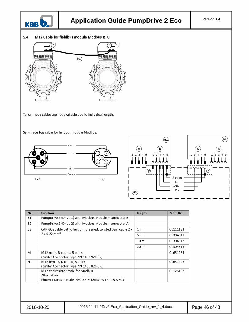
Version 1.4
Application Guide PumpDrive 2 Eco
2016-10-20 2016-11-11 PDrv2-Eco_Application_Guide_rev_1_4.docx
Page 46 of 48
63
B A
5
3
4 1
2
5
4
32
1
D +
GND
D -
M N
Screen
1 2 3 4 51 2 3 4 5
D +
D -
GND
NM
60
5251
AB
1 2 3 4 5 1 2 3 4 5
A B
Screen
5.4 M12 Cable for fieldbus module Modbus RTU
Tailor-made cables are not available due to individual length. Self-made bus cable for fieldbus module Modbus:
Nr. function length Mat.-Nr.
51 PumpDrive 2 (Drive 1) with Modbus Module – connector B
52 PumpDrive 2 (Drive 2) with Modbus Module – connector A
63 CAN-Bus cable cut to length, screened, twisted pair, cable 2 x 2 x 0,22 mm²
1 m 01111184
5 m 01304511
10 m 01304512
20 m 01304513
M M12 male, B-coded, 5 poles (Binder Connector Type: 99 1437 920 05)
01651264
N M12 female, B-coded, 5 poles (Binder Connector Type: 99 1436 820 05)
01651298
- M12 end resistor male for Modbus Alternative: Phoenix Contact male: SAC-5P-M12MS PB TR - 1507803
01125102

Version 1.4
Application Guide PumpDrive 2 Eco
2016-10-20 2016-11-11 PDrv2-Eco_Application_Guide_rev_1_4.docx
Page 47 of 48
6. Project
Description:
DI-EN+24V
GND
DI3
DI2DI1
+24V
DICOM
AO-GND
AO
AIN2
NO
+24V
GND
COM+24V
B1
B2
B3
B4
B5
B6
B7
B8
B9
B10
A1
A2
A3
A4
A5
A6
A7
A8
A9
A10
GND
GNDAIN1
+24V
Nr. Parameter Change value to Changeable by
Nr. Function
PDrv 2 Eco Or local Or PLC Drive

Version 1.4
Application Guide PumpDrive 2 Eco
2016-10-20 2016-11-11 PDrv2-Eco_Application_Guide_rev_1_4.docx
Page 48 of 48
7. Other documents
PumpDrive 2 - PumpDrive 2 Eco Type Series Booklet 4074.5 https://shop.ksb.com/document/ES000911/4074.5_EN Pump Drive 2 – Application Guide 4074.51 https://shop.ksb.com/document/ES000911/4074.51_EN
Pump Drive 2 Eco – Application Guide 4074.52 https://shop.ksb.com/document/ES000911/4074.52_EN
Pump Drive 2 – Operating manual 4074.81 https://shop.ksb.com/document/ES000911/4074.81_EN
Pump Drive 2 Eco – Operating manual 4074.82 https://shop.ksb.com/document/ES000911/4074.82_EN
PumpMeter - Type Series Booklet 4072.5 https://shop.ksb.com/document/ES000807/4072.5_EN
PumpMeter - Operating manual 4072.8 https://shop.ksb.com/document/ES000807/4072.8_EN
Pump Drive 2 - Modbus supplementary operating manual 4074.803 https://shop.ksb.com/document/ES000911/4074.803_EN

4074
.52/
04-E
N26
.04.
2017
KSB Aktiengesellschaft67225 Frankenthal • Johann-Klein-Str. 9 • 67227 Frankenthal (Deutschland)Tel. +49 6233 86-0 • Fax +49 6233 86-3401www.ksb.de


![Type Series Booklet Vitacast - shop.ksb.com · 1) Fluid temperatureT [°C] ≤ 140. 1) Connection sizesDN 32 - 200. ... 341Drive lantern1.4308 (AISI CF8) 890Baseplate 1.4301 (AISI](https://img.pdfslide.us/doc/110x75/5c7347cd09d3f285208c6c7d/type-series-booklet-vitacast-shopksbcom-1-fluid-temperaturet-c-.jpg)