Embed Size (px)
Citation preview
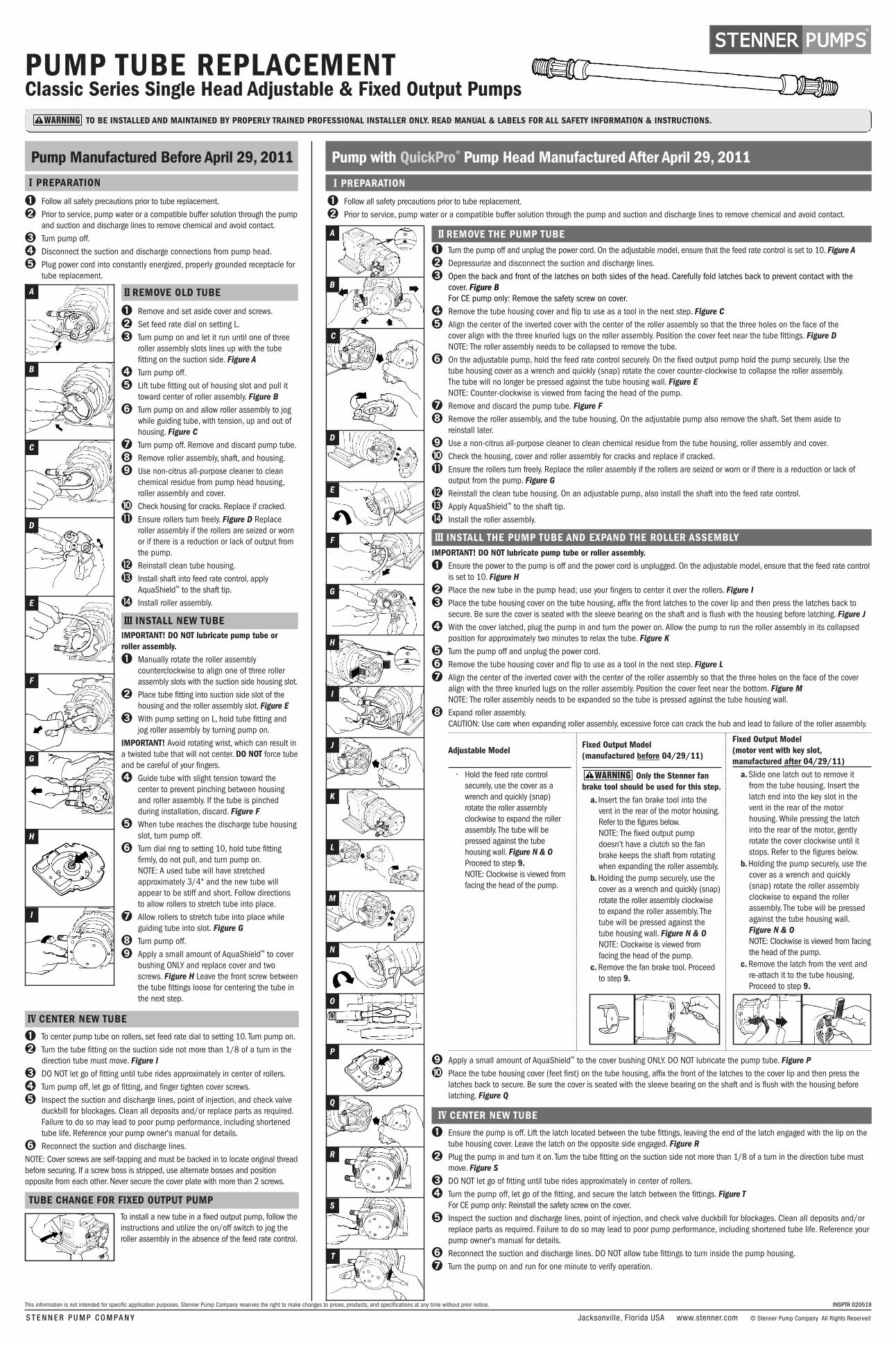
PUMP TUBE REPLACEMENTClassic Series Single Head Adjustable & Fixed Output Pumps
II REMOVE OLD TUBE
➊ Remove and set aside cover and screws. ➋ Set feed rate dial on setting L.➌ Turn pump on and let it run until one of three
roller assembly slots lines up with the tubefitting on the suction side. Figure A
➍ Turn pump off.➎ Lift tube fitting out of housing slot and pull it
toward center of roller assembly. Figure B➏ Turn pump on and allow roller assembly to jog
while guiding tube, with tension, up and out ofhousing. Figure C
➐ Turn pump off. Remove and discard pump tube.➑ Remove roller assembly, shaft, and housing.➒ Use non-citrus all-purpose cleaner to clean
chemical residue from pump head housing,roller assembly and cover.
➓ Check housing for cracks. Replace if cracked.⓫ Ensure rollers turn freely. Figure D Replace
roller assembly if the rollers are seized or wornor if there is a reduction or lack of output fromthe pump.
⓬ Reinstall clean tube housing.⓭ Install shaft into feed rate control, apply
AquaShield™ to the shaft tip.⓮ Install roller assembly.
III INSTALL NEW TUBEIMPORTANT! DO NOT lubricate pump tube or roller assembly.➊ Manually rotate the roller assembly
counterclockwise to align one of three rollerassembly slots with the suction side housing slot.
➋ Place tube fitting into suction side slot of thehousing and the roller assembly slot. Figure E
➌ With pump setting on L, hold tube fitting andjog roller assembly by turning pump on.
IMPORTANT! Avoid rotating wrist, which can result ina twisted tube that will not center. DO NOT force tubeand be careful of your fingers.➍ Guide tube with slight tension toward the
center to prevent pinching between housingand roller assembly. If the tube is pinchedduring installation, discard. Figure F
➎ When tube reaches the discharge tube housingslot, turn pump off.
➏ Turn dial ring to setting 10, hold tube fittingfirmly, do not pull, and turn pump on. NOTE: A used tube will have stretchedapproximately 3/4" and the new tube willappear to be stiff and short. Follow directionsto allow rollers to stretch tube into place.
➐ Allow rollers to stretch tube into place whileguiding tube into slot. Figure G
➑ Turn pump off.➒ Apply a small amount of AquaShield™ to cover
bushing ONLY and replace cover and twoscrews. Figure H Leave the front screw betweenthe tube fittings loose for centering the tube inthe next step.
IV CENTER NEW TUBE
➊ To center pump tube on rollers, set feed rate dial to setting 10. Turn pump on.➋ Turn the tube fitting on the suction side not more than 1/8 of a turn in the
direction tube must move. Figure I➌ DO NOT let go of fitting until tube rides approximately in center of rollers. ➍ Turn pump off, let go of fitting, and finger tighten cover screws. ➎ Inspect the suction and discharge lines, point of injection, and check valve
duckbill for blockages. Clean all deposits and/or replace parts as required.Failure to do so may lead to poor pump performance, including shortenedtube life. Reference your pump owner's manual for details.
➏ Reconnect the suction and discharge lines.NOTE: Cover screws are self-tapping and must be backed in to locate original threadbefore securing. If a screw boss is stripped, use alternate bosses and positionopposite from each other. Never secure the cover plate with more than 2 screws.
TUBE CHANGE FOR FIXED OUTPUT PUMP
To install a new tube in a fixed output pump, follow theinstructions and utilize the on/off switch to jog theroller assembly in the absence of the feed rate control.
I PREPARATION
➊ Follow all safety precautions prior to tube replacement.➋ Prior to service, pump water or a compatible buffer solution through the pump
and suction and discharge lines to remove chemical and avoid contact.➌ Turn pump off.➍ Disconnect the suction and discharge connections from pump head.➎ Plug power cord into constantly energized, properly grounded receptacle for
tube replacement.
Pump Manufactured Before April 29, 2011 Pump with QuickPro® Pump Head Manufactured After April 29, 2011
I PREPARATION
➊ Follow all safety precautions prior to tube replacement.➋ Prior to service, pump water or a compatible buffer solution through the pump and suction and discharge lines to remove chemical and avoid contact.
II REMOVE THE PUMP TUBE➊ Turn the pump off and unplug the power cord. On the adjustable model, ensure that the feed rate control is set to 10. Figure A➋ Depressurize and disconnect the suction and discharge lines.➌ Open the back and front of the latches on both sides of the head. Carefully fold latches back to prevent contact with the
cover. Figure BFor CE pump only: Remove the safety screw on cover.
➍ Remove the tube housing cover and flip to use as a tool in the next step. Figure C➎ Align the center of the inverted cover with the center of the roller assembly so that the three holes on the face of the
cover align with the three knurled lugs on the roller assembly. Position the cover feet near the tube fittings. Figure DNOTE: The roller assembly needs to be collapsed to remove the tube.
➏ On the adjustable pump, hold the feed rate control securely. On the fixed output pump hold the pump securely. Use thetube housing cover as a wrench and quickly (snap) rotate the cover counter-clockwise to collapse the roller assembly.The tube will no longer be pressed against the tube housing wall. Figure ENOTE: Counter-clockwise is viewed from facing the head of the pump.
➐ Remove and discard the pump tube. Figure F➑ Remove the roller assembly, and the tube housing. On the adjustable pump also remove the shaft. Set them aside to
reinstall later.➒ Use a non-citrus all-purpose cleaner to clean chemical residue from the tube housing, roller assembly and cover.➓ Check the housing, cover and roller assembly for cracks and replace if cracked.⓫ Ensure the rollers turn freely. Replace the roller assembly if the rollers are seized or worn or if there is a reduction or lack of
output from the pump. Figure G⓬ Reinstall the clean tube housing. On an adjustable pump, also install the shaft into the feed rate control. ⓭ Apply AquaShield™ to the shaft tip. ⓮ Install the roller assembly.
III INSTALL THE PUMP TUBE AND EXPAND THE ROLLER ASSEMBLYIMPORTANT! DO NOT lubricate pump tube or roller assembly.➊ Ensure the power to the pump is off and the power cord is unplugged. On the adjustable model, ensure that the feed rate control
is set to 10. Figure H➋ Place the new tube in the pump head; use your fingers to center it over the rollers. Figure I➌ Place the tube housing cover on the tube housing, affix the front latches to the cover lip and then press the latches back to
secure. Be sure the cover is seated with the sleeve bearing on the shaft and is flush with the housing before latching. Figure J➍ With the cover latched, plug the pump in and turn the power on. Allow the pump to run the roller assembly in its collapsed
position for approximately two minutes to relax the tube. Figure K➎ Turn the pump off and unplug the power cord. ➏ Remove the tube housing cover and flip to use as a tool in the next step. Figure L➐ Align the center of the inverted cover with the center of the roller assembly so that the three holes on the face of the cover
align with the three knurled lugs on the roller assembly. Position the cover feet near the bottom. Figure MNOTE: The roller assembly needs to be expanded so the tube is pressed against the tube housing wall.
➑ Expand roller assembly.CAUTION: Use care when expanding roller assembly, excessive force can crack the hub and lead to failure of the roller assembly.
➒ Apply a small amount of AquaShield™ to the cover bushing ONLY. DO NOT lubricate the pump tube. Figure P➓ Place the tube housing cover (feet first) on the tube housing, affix the front of the latches to the cover lip and then press the
latches back to secure. Be sure the cover is seated with the sleeve bearing on the shaft and is flush with the housing beforelatching. Figure Q
Fixed Output Model(manufactured before 04/29/11)
Only the Stenner fanbrake tool should be used for this step.a. Insert the fan brake tool into thevent in the rear of the motor housing.Refer to the figures below.NOTE: The fixed output pumpdoesn’t have a clutch so the fanbrake keeps the shaft from rotatingwhen expanding the roller assembly.
b.Holding the pump securely, use thecover as a wrench and quickly (snap)rotate the roller assembly clockwiseto expand the roller assembly. Thetube will be pressed against thetube housing wall. Figure N & ONOTE: Clockwise is viewed fromfacing the head of the pump.
c. Remove the fan brake tool. Proceedto step 9.
Fixed Output Model(motor vent with key slot,manufactured after 04/29/11)a.Slide one latch out to remove itfrom the tube housing. Insert thelatch end into the key slot in thevent in the rear of the motorhousing. While pressing the latchinto the rear of the motor, gentlyrotate the cover clockwise until itstops. Refer to the figures below.
b.Holding the pump securely, use thecover as a wrench and quickly(snap) rotate the roller assemblyclockwise to expand the roller assembly. The tube will be pressedagainst the tube housing wall.Figure N & ONOTE: Clockwise is viewed from facingthe head of the pump.
c. Remove the latch from the vent andre-attach it to the tube housing.Proceed to step 9.
IV CENTER NEW TUBE
➊ Ensure the pump is off. Lift the latch located between the tube fittings, leaving the end of the latch engaged with the lip on thetube housing cover. Leave the latch on the opposite side engaged. Figure R
➋ Plug the pump in and turn it on. Turn the tube fitting on the suction side not more than 1/8 of a turn in the direction tube mustmove. Figure S
➌ DO NOT let go of fitting until tube rides approximately in center of rollers. ➍ Turn the pump off, let go of the fitting, and secure the latch between the fittings. Figure T
For CE pump only: Reinstall the safety screw on the cover.➎ Inspect the suction and discharge lines, point of injection, and check valve duckbill for blockages. Clean all deposits and/or
replace parts as required. Failure to do so may lead to poor pump performance, including shortened tube life. Reference yourpump owner's manual for details.
➏ Reconnect the suction and discharge lines. DO NOT allow tube fittings to turn inside the pump housing.➐ Turn the pump on and run for one minute to verify operation.
INSPTR 020519
TO BE INSTALLED AND MAINTAINED BY PROPERLY TRAINED PROFESSIONAL INSTALLER ONLY. READ MANUAL & LABELS FOR ALL SAFETY INFORMATION & INSTRUCTIONS.
A
B
C
D
E
F
G
H
I
A
B
C
D
E
F
G
H
I
J
K
L
M
N
O
P
Q
R
S
T
Jacksonville, Florida USA www.stenner.com © Stenner Pump Company All Rights Reserved
This information is not intended for specific application purposes. Stenner Pump Company reserves the right to make changes to prices, products, and specifications at any time without prior notice.
WARNING
Adjustable Model
• Hold the feed rate controlsecurely, use the cover as awrench and quickly (snap)rotate the roller assemblyclockwise to expand the rollerassembly. The tube will bepressed against the tubehousing wall. Figure N & OProceed to step 9. NOTE: Clockwise is viewed fromfacing the head of the pump.
WARNING
S T E N N E R P U M P C O M PA N Y
IV CENTRE EL TUBO
➊ Para centrar el tubo en los rodillos, coloque el cuadrante en el número 10. Encienda eldosificador.
➋ Gire el conector de PVC del tubo de bombeo del lado de succión 1/8 de vuelta,hacia la dirección donde debe deslizarse el tubo. Ilustración I
➌ NO suelte el conector hasta ver que el tubo se deslice hasta aproximadamente elcentro de los rodillos.
➍ Apague el dosificador, suelte el conector y ajuste los tornillos de la cubierta a mano.Asegúrese que no quede una ranura entre la cubierta y la rosca de los tornillos.
➎ Inspeccione los tubos de succión y descarga, punto de inyección y válvula deinyección por si hay obstrucciones. Limpie los bloqueos y /o reemplace las partesque sean necesarias. De no hacerlo, puede conducir a un mal funcionamiento deldosificador, incluyendo vida útil del tubo reducida. Consulte su manual deldosificador por detalles adicionales.
➏ Reconecte los tubos de succión y descarga.NOTA: El patrón de los tornillos se hace al insertar los mismos. Para evitar barrerlo, gire eltornillo hacia atrás hasta encontrarlo y luego atornille. Si el patrón se barre, utilice losotros orificios asegurándose de utilizar solo dos tornillos a la vez y colocándolos opuestosuno del otro.
➊ Destornille y quite la cubierta del cabezal.➋ Coloque el anillo de caudal de dosificación en la
posición “L” y déjelo en esta posición hastaterminada la instalación.
➌ Encienda el dosificador y deje que gire hasta queuna de las 3 muescas en la tapa de los rodillos sealinee con la conexión del tubo en el lado desucción. Ilustración A
➍ Apague el dosificador.➎ Levante el tubo por la conexión de PVC y
gentilmente tire del mismo en dirección al centrodel cabezal. Ilustración B
➏ Encienda el dosificador y con la lenta rotación de losrodillos, sostenga al tubo por la conexión y permitaque el mismo vaya saliendo hasta quedar libre.Ilustración C
➐ Apague dosificador. Remueva el tubo y descarte el mismo.
➑ Remueva el conjunto de rodillos, el eje y la carcasa.➒ Utilice un limpiador no-cítrico para limpiar residuos de
químicos del cabezal, conjunto de rodillos y carcasa.➓ Revise la carcasa por quebraduras. Cambie por una
nueva si es necesario.⓫ Asegúrese que los rodillos giren libremente.
Ilustración D Cambie el conjunto de rodillos si losmismos están trancados o desgastados, o si hayuna reducción de caudal.
⓬ Reinstale la carcasa.⓭ Aplique grasa AquaShield™ a la punta del eje y
reinstale en el controlador de caudal.⓮ Instale el conjunto de rodillos.
II QUITE EL TUBO DE BOMBEO VIEJO
CAMBIO DE TUBO EN DOSIFICADORES DE CAUDAL FIJOPara instalar un tubo nuevo en un dosificador de caudalfijo, siga las instrucciones indicadas previamente y utiliceel switch de prendido y apagado para rotar los rodillos deforma lenta, ya que no tiene controlador de caudal.
I PREPARACION
➊ Lea y entienda todas las precauciones y avisos antes de cambiar el tubo.➋ Bombee una cantidad generosa de agua u otro líquido neutral para limpiar todo
residuo químico y evitar contacto.➌ Apague el dosificador.➍ Desconecte los tubos de succión y descarga del cabezal de la bomba.➎ Enchufe en un receptáculo con conexión a tierra adecuado y con corriente continua
para realizar el cambio de tubo.
Dosificador fabricado antes del 29 de Abril del 2011 Dosificador con cabezal QuickPro®, fabricado después del 29 de Abril del 2011
I PREPARACION
II QUITE EL TUBO DE BOMBEO VIEJO➊ Asegúrese que el dosificador no esté conectado. En los modelos de caudal ajustable,verifique que el anillo de caudal esté ubicado en
el 10. Ilustración A➋ Purgue la presión y desconecte los tubos de succión y descarga.➌ Abra los ajustadores de ambos lados del cabezal. Dóblelos cuidadosamente hacia atrás para prevenir golpearlos en el próximo paso.
Ilustración BDosificadores CE solamente: Remueva el tornillo de seguridad de la tapa.
➍ Remueva la tapa del cabezal y voltéela para usarla como herramienta en el próximo paso. Ilustración C➎ Alinee el centro de la tapa volteada con el centro del conjunto de rodillos de manera que los tres agujeros en la tapa queden
alineados con los tres remaches en relieve del conjunto de rodillos. Posicione las aberturas de tubos de la tapa cerca de lasconexiones de los tubos. Ilustración DNOTA: El conjunto de rodillos debe estar contraído para poder remover el tubo.
➏ En dosificadores de caudal ajustable; sostenga el controlador de caudal firmemente. En los dosificadores de caudal fijo, sostenga elmotor. Usando la tapa como herramienta, gire la misma rápidamente (con un movimiento corto y veloz) contra reloj, para contraer elconjunto de rodillos. Ilustración ENOTA: Contra reloj es visto del frente del cabezal.
➐ Remueva y descarte el tubo. Ilustración F➑ Remueva el conjunto de rodillos y la carcasa del cabezal. En los dosificadores ajustables, también remueva el eje y coloque todo a su
costado para reinstalar más adelante.➒ Utilice un limpiador multiuso no-cítrico para limpiar los residuos de químicos del cabezal, rodillos y tapa.➓ Chequee la carcasa, la cubierta y el conjunto de rodillos por quebraduras y reemplace si es necesario. ⓫ Asegúrese que los rodillos giren libremente. Cambie el conjunto de rodillos si los mismos están trancados o desgastados, o si hay una
reducción de caudal. Ilustración G⓬ Reinstale la carcasa limpia. En dosificadores ajustables, también instale el eje en el controlador de caudal.⓭ Aplique grasa a la punta del eje.⓮ Instale el conjunto de rodillos.
III INSTALE EL TUBO Y EXPANDA EL CONJUNTO DE RODILLOSIMPORTANTE! No lubrique el tubo o el conjunto de rodillos.➊ Asegúrese que el dosificador no esté conectado. En los modelos de caudal ajustable, verifique que el anillo de caudal esté ubicado en el 10.
Ilustración H➋ Coloque el tubo nuevo en el cabezal. Utilice sus dedos para centrarlo en los rodillos. Ilustración I➌ Coloque la tapa del cabezal y cierre los sujetadores en ambos lados. Confirme la tapa esté colocada en el eje y asentada en la carcasa
antes de cerrar los sujetadores. Ilustración J➍ Con la tapa instalada, prenda el dosificador y déjelo prendido, con el conjunto de rodillos contraídos, por dos minutos, para relajar el tubo
de bombeo. Ilustración K➎ Apague el dosificador y desenchufe.➏ Remueva la tapa y voltéela para usar como herramienta en el próximo paso. Ilustración L➐ Alinee el centro de la tapa volteada con el centro del conjunto de rodillos de manera que los tres agujeros en la tapa queden alineados
con los tres remaches en relieve del conjunto de rodillos. Posicione las aberturas de tubos de la tapa cerca de las conexiones de lostubos. Ilustración MNOTA: El conjunto de rodillos debe estar expandido para presionar el tubo contra las paredes del cabezal.
➑ Expanda el conjunto de rodillos. Tenga cuidado al expandir el conjunto de rodillos, fuerza excesiva puede quebrar el centro y provocar unafalla del conjunto.
➒ Aplique una pequeña cantidad de grasa al cojinete de la tapa del cabezal SOLAMENTE. NO lubrique el tubo de bombeo. Ilustración P➓ Reinstale la tapa del cabezal, cierre los sujetadores de ambos lados del cabezal. Confirme la tapa esté colocada en el eje y asentada en la
carcasa antes de cerrar los sujetadores. Ilustración Q
Modelos de Caudal Fijo (fabricados antesdel 29 de Abril del 2011)
Solamente el freno deventilador hecho por Stenner debe usarsepara este procedimiento. a. Inserte el freno de ventilador en la parte trasera del motor. Vea lasilustraciones abajo.
NOTA: El dosificador de caudal fijo notiene embrague y el freno de ventiladorpreviene la rotación del eje cuando seexpanden los rodillos.
b. Sostenga el dosificador con firmeza ygire la tapa de forma rápida (con unmovimiento corto y veloz), en direccióndel reloj, para expandir los rodillos. Eltubo estará presionado contra lasparedes del cabezal. Ilustración N & ONOTA: Dirección del reloj es visto delfrente del cabezal.
c. Remueva el freno de ventilador. Procedaal paso 9.
Modelos de Caudal Fijo (ventilador demotor con ranura especial, fabricadodespués del 29 de Abril del 2011)a. Deslice un sujetador de la carcasa delcabezal. Inserte el extremo deslizado enla ranura de la parte trasera del motor.Mientras mantiene el sujetador en laranura, gire la tapa suavemente endirección del reloj hasta que sedetenga. Vea ilustraciones abajo.
b. Sostenga el dosificador con firmeza ygire la tapa de forma rápida (con unmovimiento corto y veloz), en direccióndel reloj, para expandir los rodillos. Eltubo estará presionado contra lasparedes del cabezal. Ilustración N & ONOTA: Dirección del reloj es visto delfrente del cabezal.
c. Remueva el sujetador de la ranura delmotor y reinstale en su lugar, en lacarcasa del cabezal. Proceda al paso 9.
IV CENTRE EL TUBO➊ Asegúrese el dosificador está apagado. Levante la parte trasera del sujetador que se encuentra entre las conexiones de tubos, dejando la
parte delantera del mismo enganchada en el labio de la carcasa. Deje el otro sujetador completamente cerrado. Ilustración R➋ Prenda el dosificador y gire la conexión de tubo del lado de succión hacia donde deba moverse (no más de 1/8 de giro). Ilustración S➌ NO suelte la conexión hasta que el tubo se encuentre centrado sobre los rodillos.➍ Apague el dosificador, suelte la conexión y cierre el sujetador colocado entre las conexiones. Ilustración T
Dosificadores CE solamente: Reinstale el tornillo de seguridad en la tapa. ➎ Inspeccione los tubos de succión y descarga, punto de inyección y válvula de inyección por si hay obstrucciones. Limpie los bloqueos y /o
reemplace las partes que sean necesarias. De no hacerlo, puede conducir a un mal funcionamiento del dosificador, incluyendo vida útildel tubo reducida. Consulte su manual del dosificador por detalles adicionales.
➏ Reconecte los tubos de succión y descarga. NO permita que las conexiones de tubo se retuerzan dentro de la carcasa del cabezal.➐ Prenda el dosificador por un minuto para verificar su funcionamiento.
A
B
C
D
E
F
G
H
I
III INSTALE EL TUBO NUEVOIMPORTANTE! No lubrique el tubo o el conjunto de rodillos.➊ Alinee, girando manualmente en sentido contrario a
las agujas del reloj, una de las muescas del conjuntode rodillos con la ranura de entrada de la carcasa.
➋ Coloque la conexión de PVC del tubo en la ranura dela carcasa y el tubo en la muesca de los rodillos.Ilustración E
➌ Con el controlador en “L”, sostenga la otra conexióndel tubo y prenda el dosificador. El tubo se instala algirar los rodillos.
IMPORTANTE! NO gire la muñeca, ya que podría retorcerel tubo y luego no podrá centrarlo. NO fuerce el tubo ytenga cuidado con sus dedos.➍ Guíe el tubo con tensión leve hacia el centro, para
prevenir que se pellizque o tranque entre la carcasay los rodillos. Descarte el tubo si se dañó durante lainstalación. Ilustración F
➎ Cuando el tubo llegue a la ranura de descarga de lacarcasa, apague el dosificador.
➏ Gire el anillo/cuadrante al número 10, sostenga eltubo por la conexión de PVC firmemente y enciendael dosificador.NOTA: Un tubo usado estará estirado unos 2 cm y eltubo nuevo aparentará corto y rígido. Siga lasinstrucciones para estirar el tubo y poder instalarloen su lugar.
➐ Permita que los rodillos estiren el tubo hasta quealcance la ranura de la carcasa. Ilustración G
➑ Apague el dosificador.➒ Aplique una pequeña cantidad de grasa
(AquaShield™) al buje de la carcasa SOLAMENTE ycoloque la cubierta y los dos tornillos Ilustración HDeje el tornillo de adelante, entre las conexiones delos tubos, algo suelto, para centrar el tubo en elpróximo paso de la instalación.
➊ Siga todas las precauciones de seguridad antes de cambiar el tubo.➋ Antes de realizar el servicio, bombee una cantidad generosa de agua o solución neutral para limpiar todo residuo químico y evitar el contacto.
ADVERTENCIA INSTALACION DEBE SER REALIZADA Y MANTENIDA POR PROFESIONALES DEBIDAMENTE ENTRENADOS. LEA EL MANUAL Y LAS ETIQUETAS PARA OBTENER LAS INSTRUCCIONES Y LA INFORMACION DE SEGURIDAD.
INSPTR 020519
A
B
C
D
E
F
G
H
I
J
K
L
M
N
O
P
Q
R
S
T
Jacksonville, Florida USA www.stenner.com © Stenner Pump Company Derechos Reservados
Esta información no está prevista con fines de aplicaciones específicas. Stenner Pump Company se reserva el derecho de efectuar cambios en los precios, productos y especificaciones, en cualquier momento y sin previo aviso.
S T E N N E R P U M P C O M PA N Y
Modelos de Caudal Ajustable
• Sujete el controlador de caudal,use la tapa como herramienta ygire la misma de forma rápida(con un movimiento corto y veloz),en dirección del reloj, paraexpandir los rodillos. El tuboestará presionado contra lasparedes del cabezal. lustración N & O NOTA: Dirección del reloj es vistodel frente del cabezal. Proceda alpaso 9.
ADVERTENCIA
CAMBIO DE TUBO DE BOMBEOModelos de Serie Clásica de un Cabezal de Caudal Ajustable y Fijo