Embed Size (px)
Citation preview
Pump Division
Pump Product Catalog
Experience In Motion
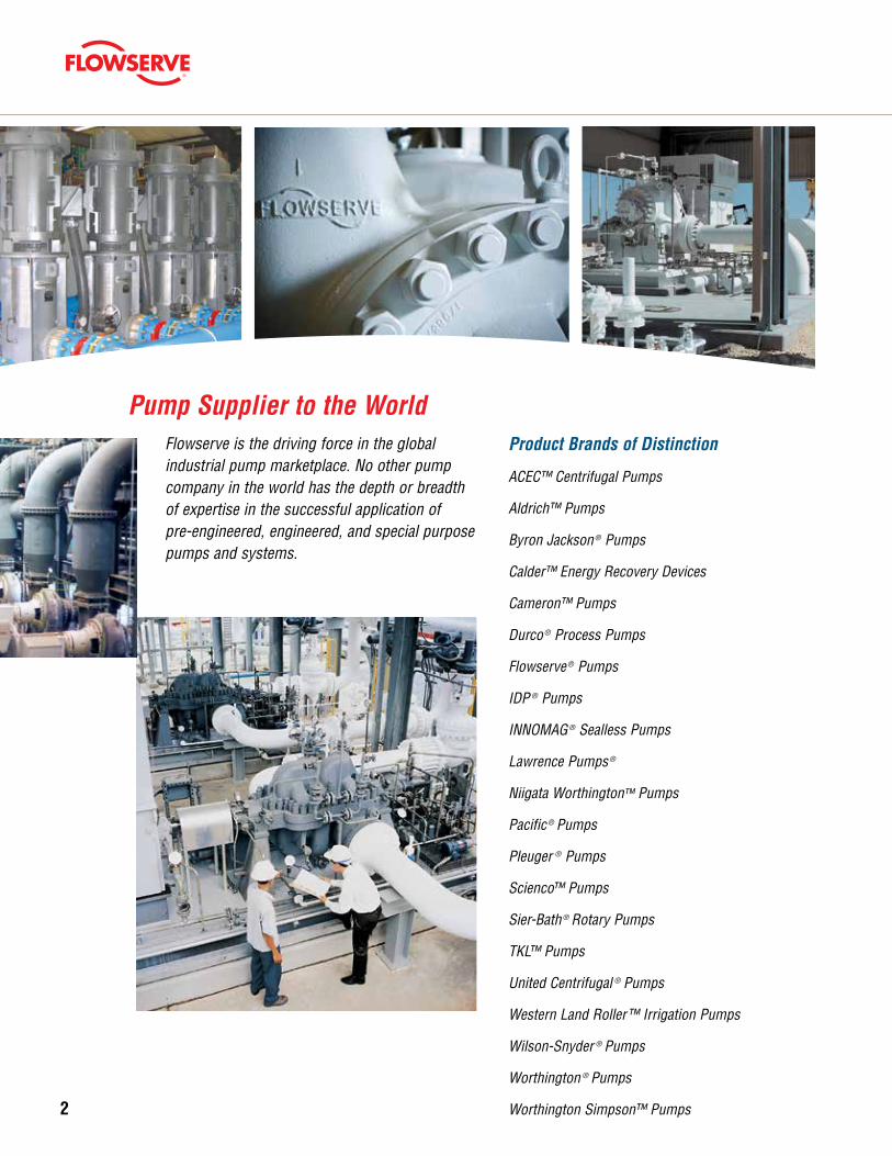
Product Brands of Distinction
ACEC™ Centrifugal Pumps
Aldrich™ Pumps
Byron Jackson ® Pumps
Calder™ Energy Recovery Devices
Cameron™ Pumps
Durco ® Process Pumps
Flowserve ® Pumps
IDP ® Pumps
INNOMAG ® Sealless Pumps
Lawrence Pumps ®
Niigata Worthington™ Pumps
Pacific ® Pumps
Pleuger ® Pumps
Scienco™ Pumps
Sier-Bath ® Rotary Pumps
TKL™ Pumps
United Centrifugal ® Pumps
Western Land Roller™ Irrigation Pumps
Wilson-Snyder ® Pumps
Worthington ® Pumps
Worthington Simpson™ Pumps
Flowserve is the driving force in the global industrial pump marketplace. No other pump company in the world has the depth or breadth of expertise in the successful application of pre-engineered, engineered, and special purpose pumps and systems.
Pump Supplier to the World
2
3
flowserve.com
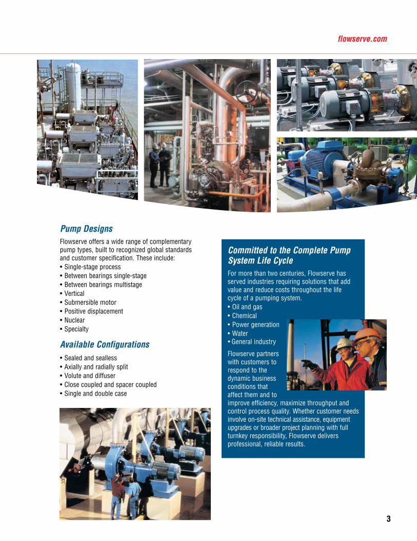
Committed to the Complete Pump System Life CycleFor more than two centuries, Flowserve has served industries requiring solutions that add value and reduce costs throughout the life cycle of a pumping system.• Oil and gas• Chemical• Power generation• Water• General industry
Flowserve partners with customers to respond to the dynamic business conditions that affect them and to improve efficiency, maximize throughput and control process quality. Whether customer needs involve on-site technical assistance, equipment upgrades or broader project planning with full turnkey responsibility, Flowserve delivers professional, reliable results.
Pump DesignsFlowserve offers a wide range of complementary pump types, built to recognized global standards and customer specification. These include: • Single-stage process • Between bearings single-stage• Between bearings multistage• Vertical • Submersible motor• Positive displacement• Nuclear• Specialty
Available Configurations• Sealed and sealless• Axially and radially split• Volute and diffuser• Close coupled and spacer coupled• Single and double case
4
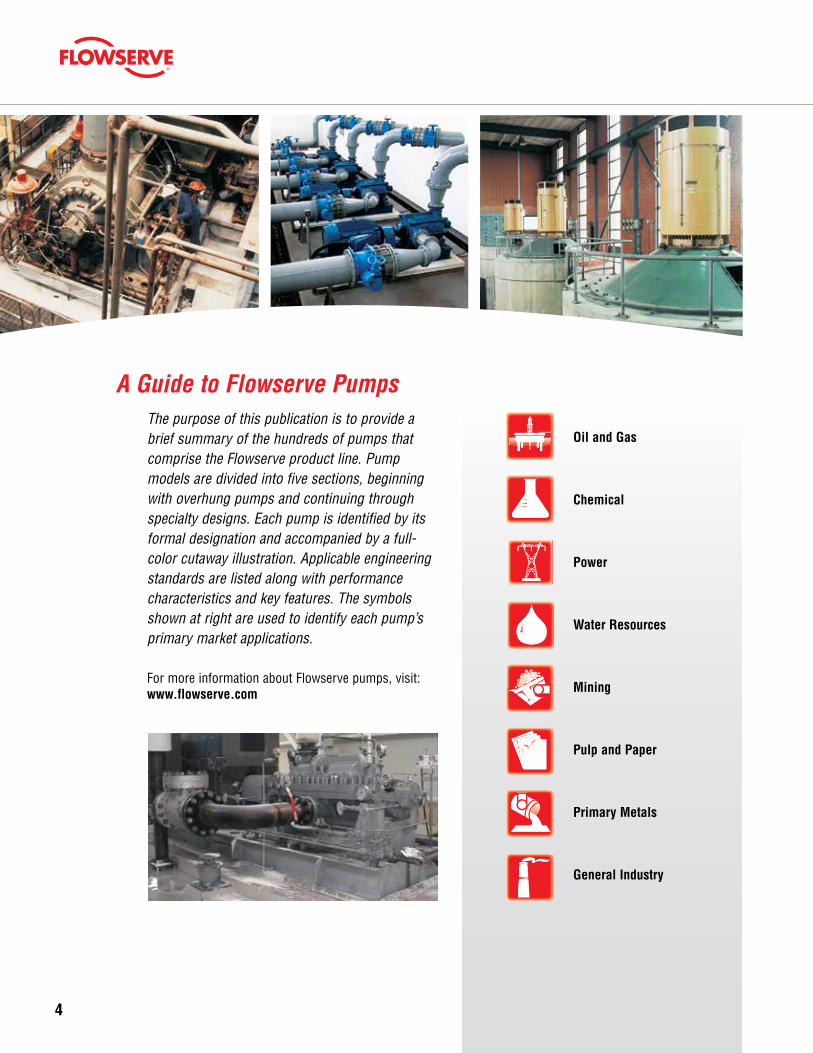
A Guide to Flowserve PumpsThe purpose of this publication is to provide a brief summary of the hundreds of pumps that comprise the Flowserve product line. Pump models are divided into five sections, beginning with overhung pumps and continuing through specialty designs. Each pump is identified by its formal designation and accompanied by a full-color cutaway illustration. Applicable engineering standards are listed along with performance characteristics and key features. The symbols shown at right are used to identify each pump’s primary market applications.
For more information about Flowserve pumps, visit: www.flowserve.com
Oil and Gas
Chemical
Power
Water Resources
Mining
Pulp and Paper
Primary Metals
General Industry
5
flowserve.com
Table of ContentsPump Selection Guide .........................................6 – 7
Overhung Pumps
Product List ..............................................................9
Chemical Process ............................................10 – 15
API Process .....................................................16 – 18
Slurry and Solids Handling ..............................19 – 22
Industrial Process ............................................23 – 25
Between Bearings Pumps
Product List ............................................................27
Single Case — Axially Split — Single-Stage .......28 – 29
Single Case — Axially Split — Multistage .................30
Single Case — Radially Split — Single-Stage ............31
Single Case — Radially Split — Multistage ........32 – 34
Double Case .....................................................35 – 37
Vertical Pumps
Product List ............................................................39
Wet-Pit .............................................................40 – 41
Double Case .....................................................42 – 43
Submersible ............................................................44
Slurry and Solids Handling ..............................45 – 47
Sump ...............................................................48 – 49
Positive Displacement
Product List ............................................................51
Gear ........................................................................52
Screw ......................................................................53
Reciprocating ..........................................................54
Specialty Products
Product List ............................................................57
Nuclear Pumps and Seals ................................58 – 61
Extreme Temperature Pumps ..................................62
Others ..............................................................63 – 65
Additional Information
Introduction ............................................................67
Integrated Solutions Group ..............................68 – 69
Other Flowserve Products .......................................70
Reference Sources ..................................................71
Index
Product List .....................................................72 – 73
Oil and GasChemical Processing
Power Generation(Fossil, Renewables, Nuclear)
Power Generation(Fossil, Renewables,
Nuclear)Water Resources Primary Metals Mining Pulp and Paper General Industry
Downstream Upstream and Pipeline
Pump Category Sub-Category Di
still
atio
n
Hydr
otre
atin
g
Hydr
ocra
ckin
g
Cata
lytic
Cra
ckin
g
Resi
duum
and
Hea
vy O
il Up
grad
ing
Gas
Trea
ting
and
Sulfu
r Rec
over
y
LNG
NGL
and
LPG
Gas
to L
iqui
ds
Off-s
ites
and
Was
te T
reat
men
t
Heav
y Oi
l, Oi
l San
ds a
nd S
hale
Crud
e, P
rodu
ct a
nd C
O 2 P
ipel
ine
Drill
ing
and
Prod
uctio
n
FPSO
Wat
er a
nd C
O 2 In
ject
ion
Wat
er S
uppl
y an
d Tr
eatm
ent
Acid
Tra
nsfe
r
Caus
tic a
nd C
hlor
-Alk
ali
Phar
mac
eutic
als
Poly
mer
s
Rene
wab
le F
uel P
rodu
ctio
n
Slur
ry P
roce
ssin
g
Solv
ents
Vola
tile
Orga
nic
Com
poun
ds
Was
te P
roce
ssin
g
Auxi
liary
Boile
r Fee
d
Boile
r Fee
d Bo
oste
r
Cond
ensa
te E
xtra
ctio
n
Cool
ing
Wat
er
Flue
Gas
Des
ulfu
rizat
ion
Geot
herm
al W
ell S
ervi
ces
Heat
Tra
nsfe
r Flu
ids
Mol
ten
Salt
Tran
sfer
Tran
sfor
mer
Coo
ling
Auxi
liary
Ser
vice
s
Nucl
ear S
ervi
ce
Desa
linat
ion
Floo
d Co
ntro
l
Grou
ndw
ater
Dev
elop
men
t and
Irrig
atio
n
Sew
age
Colle
ctio
n an
d Tr
eatm
ent
Wat
er S
uppl
y an
d Di
strib
utio
n
Wat
er T
reat
men
t
Cool
ing
Wat
er
Desc
alin
g
Hydr
aulic
Pre
ss
Plat
ing,
Gal
vani
zing
and
Othe
r Coa
tings
Scal
e Re
cycl
e
Dew
ater
ing
and
Wat
er S
uppl
y
Leac
hing
Aci
d
Prim
ary
Proc
essi
ng
Slur
ry T
rans
fer
Blea
ch C
hem
ical
Boile
r Fee
d
Chem
ical
and
Liq
uor
Coat
ings
Dige
ster
Pape
r Sto
ck
Show
er P
umps
Auto
mot
ive
Agric
ultu
re
Cons
truct
ion
Indu
stria
l Gas
es
Elec
troni
cs
Fire
Pro
tect
ion
Food
Pro
cess
ing
HVAC
OEM
Ship
ping
Snow
mak
ing
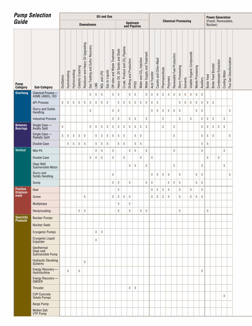
Overhung Chemical Process — ASME (ANSI), ISO X X X X X X X X X X X X X X X X X X X X X X X X X X X X X X X X X X X X X X X X X
API Process X X X X X X X X X X X X X X X X X X X X X X X X X X X X X X X X X X X
Slurry and Solids Handling X X X X X X X X X X X X X X X X X X X X X X X X X X X X X X X X
Industrial Process X X X X X X X X X X X X X X X X X X X X X X X X X X X X X X X
Between Bearings
Single Case — Axially Split X X X X X X X X X X X X X X X X X X X X X X X X X X X X X X X X X X X X X X X X X
Single Case — Radially Split X X X X X X X X X X X X X X X X X X X X X X X X X X X X X X X X X X X X X X X
Double Case X X X X X X X X X X X X X X X X X X X
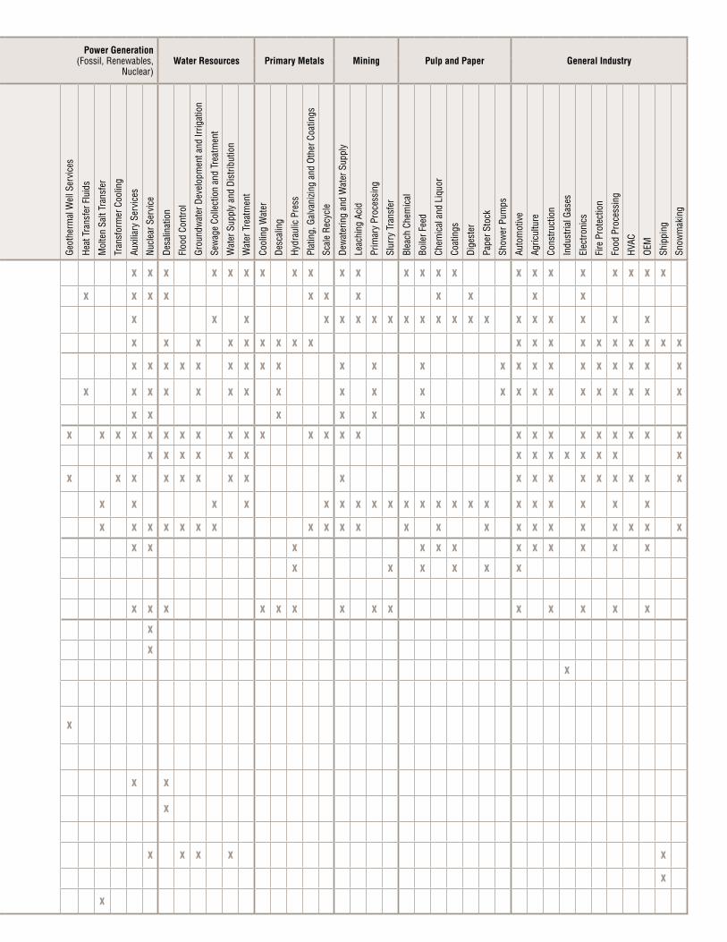
Vertical Wet-Pit X X X X X X X X X X X X X X X X X X X X X X X X X X X X X X X X X
Double Case X X X X X X X X X X X X X X X X X X X X X X X
Deep Well Submersible Motor X X X X X X X X X X X X X X X X X X X X X X X X
Slurry and Solids Handling X X X X X X X X X X X X X X X X X X X X X X X X X X X X X X
Sump X X X X X X X X X X X X X X X X X X X X X X X X X X X X X X X X
Positive Displace-ment
Gear X X X X X X X X X X X X X X X X X X X X
Screw X X X X X X X X X X X X X X X X X X X
Multiphase X X
Reciprocating X X X X X X X X X X X X X X X X X X X X X X
Specialty Products
Nuclear Pumps X
Nuclear Seals X
Cryogenic Pumps X X X
Cryogenic Liquid Expander X
Geothermal Deep well Submersible Pump
X
Hydraulic Decoking Systems X
Energy Recovery — Hydroturbine X X X X X
Energy Recovery — DWEER X
Thruster X X
CVP Concrete Volute Pumps X X X X X X
Barge Pump X
Molten Salt VTP Pump X
Pump Selection Guide
flowserve.comOil and Gas
Chemical ProcessingPower Generation(Fossil, Renewables, Nuclear)
Power Generation(Fossil, Renewables,
Nuclear)Water Resources Primary Metals Mining Pulp and Paper General Industry
Downstream Upstream and Pipeline
Pump Category Sub-Category Di
still
atio
n
Hydr
otre
atin
g
Hydr
ocra
ckin
g
Cata
lytic
Cra
ckin
g
Resi
duum
and
Hea
vy O
il Up
grad
ing
Gas
Trea
ting
and
Sulfu
r Rec
over
y
LNG
NGL
and
LPG
Gas
to L
iqui
ds
Off-s
ites
and
Was
te T
reat
men
t
Heav
y Oi
l, Oi
l San
ds a
nd S
hale
Crud
e, P
rodu
ct a
nd C
O 2 P
ipel
ine
Drill
ing
and
Prod
uctio
n
FPSO
Wat
er a
nd C
O 2 In
ject
ion
Wat
er S
uppl
y an
d Tr
eatm
ent
Acid
Tra
nsfe
r
Caus
tic a
nd C
hlor
-Alk
ali
Phar
mac
eutic
als
Poly
mer
s
Rene
wab
le F
uel P
rodu
ctio
n
Slur
ry P
roce
ssin
g
Solv
ents
Vola
tile
Orga
nic
Com
poun
ds
Was
te P
roce
ssin
g
Auxi
liary
Boile
r Fee
d
Boile
r Fee
d Bo
oste
r
Cond
ensa
te E
xtra
ctio
n
Cool
ing
Wat
er
Flue
Gas
Des
ulfu
rizat
ion
Geot
herm
al W
ell S
ervi
ces
Heat
Tra
nsfe
r Flu
ids
Mol
ten
Salt
Tran
sfer
Tran
sfor
mer
Coo
ling
Auxi
liary
Ser
vice
s
Nucl
ear S
ervi
ce
Desa
linat
ion
Floo
d Co
ntro
l
Grou
ndw
ater
Dev
elop
men
t and
Irrig
atio
n
Sew
age
Colle
ctio
n an
d Tr
eatm
ent
Wat
er S
uppl
y an
d Di
strib
utio
n
Wat
er T
reat
men
t
Cool
ing
Wat
er
Desc
alin
g
Hydr
aulic
Pre
ss
Plat
ing,
Gal
vani
zing
and
Othe
r Coa
tings
Scal
e Re
cycl
e
Dew
ater
ing
and
Wat
er S
uppl
y
Leac
hing
Aci
d
Prim
ary
Proc
essi
ng
Slur
ry T
rans
fer
Blea
ch C
hem
ical
Boile
r Fee
d
Chem
ical
and
Liq
uor
Coat
ings
Dige
ster
Pape
r Sto
ck
Show
er P
umps
Auto
mot
ive
Agric
ultu
re
Cons
truct
ion
Indu
stria
l Gas
es
Elec
troni
cs
Fire
Pro
tect
ion
Food
Pro
cess
ing
HVAC
OEM
Ship
ping
Snow
mak
ing
Overhung Chemical Process — ASME (ANSI), ISO X X X X X X X X X X X X X X X X X X X X X X X X X X X X X X X X X X X X X X X X X
API Process X X X X X X X X X X X X X X X X X X X X X X X X X X X X X X X X X X X
Slurry and Solids Handling X X X X X X X X X X X X X X X X X X X X X X X X X X X X X X X X
Industrial Process X X X X X X X X X X X X X X X X X X X X X X X X X X X X X X X
Between Bearings
Single Case — Axially Split X X X X X X X X X X X X X X X X X X X X X X X X X X X X X X X X X X X X X X X X X
Single Case — Radially Split X X X X X X X X X X X X X X X X X X X X X X X X X X X X X X X X X X X X X X X
Double Case X X X X X X X X X X X X X X X X X X X
Vertical Wet-Pit X X X X X X X X X X X X X X X X X X X X X X X X X X X X X X X X X
Double Case X X X X X X X X X X X X X X X X X X X X X X X
Deep Well Submersible Motor X X X X X X X X X X X X X X X X X X X X X X X X
Slurry and Solids Handling X X X X X X X X X X X X X X X X X X X X X X X X X X X X X X
Sump X X X X X X X X X X X X X X X X X X X X X X X X X X X X X X X X
Positive Displace-ment
Gear X X X X X X X X X X X X X X X X X X X X
Screw X X X X X X X X X X X X X X X X X X X
Multiphase X X
Reciprocating X X X X X X X X X X X X X X X X X X X X X X
Specialty Products
Nuclear Pumps X
Nuclear Seals X
Cryogenic Pumps X X X
Cryogenic Liquid Expander X
Geothermal Deep well Submersible Pump
X
Hydraulic Decoking Systems X
Energy Recovery — Hydroturbine X X X X X
Energy Recovery — DWEER X
Thruster X X
CVP Concrete Volute Pumps X X X X X X
Barge Pump X
Molten Salt VTP Pump X
flowserve.comOverhung Pumps
Chemical ProcessMark 3™ ASME Standard 10Mark 3 Lo-Flo™ 10Mark 3 Unitized Self-Primer 10Mark 3 Recessed Impeller 11Mark 3 In-Line 11Guardian Magnetic Drive 11Mark 3 ISO Standard 12Mark 3 ISO Self-Priming 12Mark 3 ISO Recessed Impeller 12Mark 3 ISO Close Coupled 13CPXV Chemical Sump 13CPXS Magnetic Drive 13PolyChemTM GRP 14PolyChem VGRP 14PolyChem S-Series 14PolyChem M-Series 15Polyshield 15Polybase 15
API ProcessHPX 16HPXM 16PHL 16ERPN 17PVXM 17HWMA 17PVML 18MSP 18DSVP 18
Slurry and Solids HandlingM 19R 19Titan Slurry™ 19LC 20MND 20MNR 20FRBH 21FRBHJC 21MPT 21MF 22MN 22MSX 22
Industrial ProcessD800 23MEN 23MENBLOC 23ME 24DS 24SMP 24SMX 25F-Line 25MVE 25
Overhung Pumps
9

10
Overhung — Chem
ical Process
Mark 3 Lo-Flo Mark 3 ASME Standard Mark 3 Unitized Self-Primer
Standards• ASME (ANSI) B73.1
Operating Parameters• Flows to 4540 m3/h (20 000 gpm) • Heads to 215 m (700 ft) • Pressures to 27 bar (400 psi) • Temperatures from -73°C (-100°F)
to 370°C (700°F) Features • Exclusive reverse vane impeller• Standard Mark 3A power end
– External micrometer impeller adjustment mechanism
– Heavy-duty radial and thrust bearings– Double lip oil seals– Constant level oiler – Large, reflective sight glass
• Choice of lubrication systems• Optional ANSI 3A power end with lifetime warranty
– Certified clean room assembly – Inpro/Seal® VBXX isolators – Magnetic drain plug
• SealSentry™ seal chambers • Largest shaft and bearing components
in ANSI standard pumps • IPS BeaconTM electronic vibration
and temperature condition monitor
Related Configurations • Mark 3 Lo-Flo• Mark 3 Unitized Self-Primer• Mark 3 Recessed Impeller• Mark 3 Sealmatic dynamically sealed
See Bulletin PS-10-13.
Standards• ASME (ANSI) B73.1
Operating Parameters• Flows to 50 m3/h (220 gpm) • Heads to 300 m (985 ft) • Pressures to 31 bar (450 psi) • Temperatures from -73°C (-100°F)
to 370°C (700°F)
Features • Circular, concentric casing• Radial vane impeller • Standard Mark 3A power end
– External micrometer impeller adjustment mechanism
– Heavy-duty radial and thrust bearings– Double lip oil seals– Constant level oiler – Large, reflective sight glass
• Choice of lubrication systems• Optional ANSI 3A power end with lifetime warranty
– Certified clean room assembly – Inpro/Seal VBXX isolators – Magnetic drain plug
• SealSentry seal chambers• Oversized shaft and bearings• IPS Beacon electronic vibration and
temperature condition monitor
Related Configurations • Mark 3 ASME Standard• Mark 3 Recessed Impeller
See Bulletin PS-10-13.
® Inpro/Seal is a registered trademark of Inpro/Seal Company.
Standards• Flowserve
Operating Parameters• Flows to 320 m3/h (1400 gpm) • Heads to 120 m (400 ft) • Pressures to 20 bar (285 psi) • Temperatures to 370°C (700°F)• Static suction lift to 6 m (20 ft)
Features • Unitized casing with large priming
chamber, air separator and volute • Exclusive reverse vane impeller
standard; open impeller optional • Standard Mark 3A power end
– External micrometer impeller adjustment mechanism
– Heavy-duty radial and thrust bearings– Double lip oil seals– Constant level oiler – Large, reflective sight glass
• Choice of lubrication systems• Optional ANSI 3A power end with lifetime warranty
– Certified clean room assembly – Inpro/Seal VBXX isolators – Magnetic drain plug
• SealSentry seal chambers • Oversized shaft and bearings • IPS Beacon electronic vibration and
temperature condition monitor
Related Configurations • Mark 3 ASME Standard
See Bulletin PS-10-13.
11
Overhung — Chem
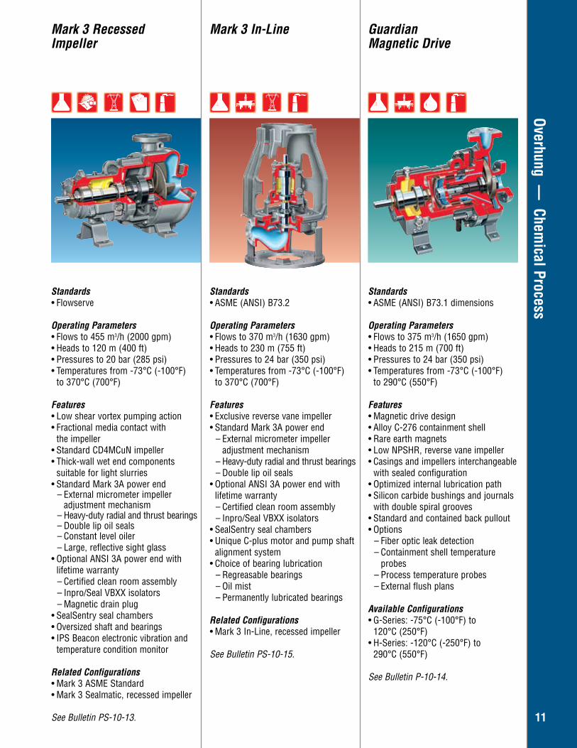
ical ProcessMark 3 Recessed Impeller
Mark 3 In-Line Guardian Magnetic Drive
Standards• Flowserve
Operating Parameters• Flows to 455 m3/h (2000 gpm) • Heads to 120 m (400 ft)• Pressures to 20 bar (285 psi)• Temperatures from -73°C (-100°F) to 370°C (700°F)
Features • Low shear vortex pumping action• Fractional media contact with the impeller• Standard CD4MCuN impeller• Thick-wall wet end components
suitable for light slurries• Standard Mark 3A power end
– External micrometer impeller adjustment mechanism
– Heavy-duty radial and thrust bearings– Double lip oil seals– Constant level oiler – Large, reflective sight glass
• Optional ANSI 3A power end with lifetime warranty
– Certified clean room assembly – Inpro/Seal VBXX isolators – Magnetic drain plug
• SealSentry seal chambers • Oversized shaft and bearings• IPS Beacon electronic vibration and
temperature condition monitor
Related Configurations • Mark 3 ASME Standard• Mark 3 Sealmatic, recessed impeller
See Bulletin PS-10-13.
Standards• ASME (ANSI) B73.2
Operating Parameters• Flows to 370 m3/h (1630 gpm) • Heads to 230 m (755 ft) • Pressures to 24 bar (350 psi) • Temperatures from -73°C (-100°F)
to 370°C (700°F)
Features• Exclusive reverse vane impeller• Standard Mark 3A power end
– External micrometer impeller adjustment mechanism
– Heavy-duty radial and thrust bearings– Double lip oil seals
• Optional ANSI 3A power end with lifetime warranty– Certified clean room assembly – Inpro/Seal VBXX isolators
• SealSentry seal chambers • Unique C-plus motor and pump shaft
alignment system• Choice of bearing lubrication
– Regreasable bearings – Oil mist – Permanently lubricated bearings
Related Configurations • Mark 3 In-Line, recessed impeller
See Bulletin PS-10-15.
Standards• ASME (ANSI) B73.1 dimensions
Operating Parameters• Flows to 375 m3/h (1650 gpm) • Heads to 215 m (700 ft)• Pressures to 24 bar (350 psi) • Temperatures from -73°C (-100°F)
to 290°C (550°F) Features• Magnetic drive design• Alloy C-276 containment shell• Rare earth magnets• Low NPSHR, reverse vane impeller • Casings and impellers interchangeable
with sealed configuration• Optimized internal lubrication path • Silicon carbide bushings and journals
with double spiral grooves • Standard and contained back pullout• Options
– Fiber optic leak detection – Containment shell temperature
probes – Process temperature probes – External flush plans
Available Configurations• G-Series: -75°C (-100°F) to
120°C (250°F)• H-Series: -120°C (-250°F) to
290°C (550°F)
See Bulletin P-10-14.
12
Overhung — Chem
ical Process
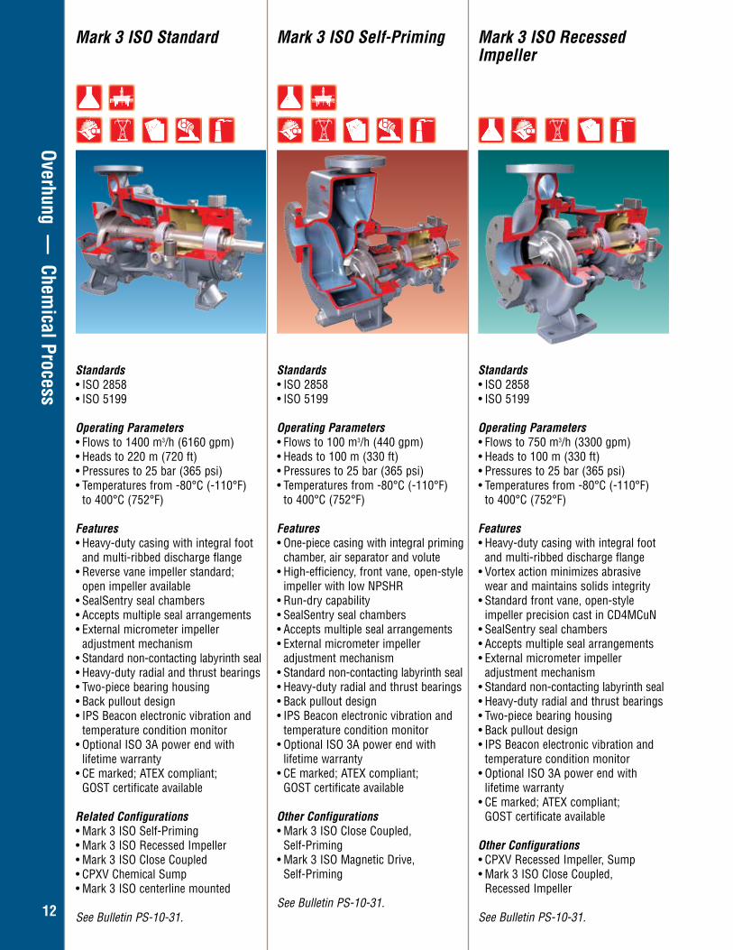
Mark 3 ISO Self-Priming Mark 3 ISO Recessed Impeller
Standards• ISO 2858• ISO 5199
Operating Parameters• Flows to 100 m3/h (440 gpm)• Heads to 100 m (330 ft)• Pressures to 25 bar (365 psi)• Temperatures from -80°C (-110°F)
to 400°C (752°F) Features• One-piece casing with integral priming
chamber, air separator and volute• High-efficiency, front vane, open-style
impeller with low NPSHR• Run-dry capability• SealSentry seal chambers• Accepts multiple seal arrangements• External micrometer impeller
adjustment mechanism• Standard non-contacting labyrinth seal• Heavy-duty radial and thrust bearings• Back pullout design• IPS Beacon electronic vibration and
temperature condition monitor• Optional ISO 3A power end with
lifetime warranty• CE marked; ATEX compliant;
GOST certificate available
Other Configurations• Mark 3 ISO Close Coupled,
Self-Priming• Mark 3 ISO Magnetic Drive,
Self-Priming
See Bulletin PS-10-31.
Standards• ISO 2858• ISO 5199
Operating Parameters• Flows to 750 m3/h (3300 gpm)• Heads to 100 m (330 ft)• Pressures to 25 bar (365 psi)• Temperatures from -80°C (-110°F)
to 400°C (752°F) Features• Heavy-duty casing with integral foot
and multi-ribbed discharge flange• Vortex action minimizes abrasive
wear and maintains solids integrity• Standard front vane, open-style
impeller precision cast in CD4MCuN• SealSentry seal chambers• Accepts multiple seal arrangements• External micrometer impeller
adjustment mechanism• Standard non-contacting labyrinth seal• Heavy-duty radial and thrust bearings• Two-piece bearing housing• Back pullout design• IPS Beacon electronic vibration and
temperature condition monitor• Optional ISO 3A power end with
lifetime warranty• CE marked; ATEX compliant;
GOST certificate available
Other Configurations• CPXV Recessed Impeller, Sump • Mark 3 ISO Close Coupled,
Recessed Impeller
See Bulletin PS-10-31.
Mark 3 ISO Standard
Standards• ISO 2858• ISO 5199
Operating Parameters• Flows to 1400 m3/h (6160 gpm)• Heads to 220 m (720 ft)• Pressures to 25 bar (365 psi)• Temperatures from -80°C (-110°F)
to 400°C (752°F) Features• Heavy-duty casing with integral foot
and multi-ribbed discharge flange• Reverse vane impeller standard;
open impeller available• SealSentry seal chambers• Accepts multiple seal arrangements• External micrometer impeller
adjustment mechanism• Standard non-contacting labyrinth seal• Heavy-duty radial and thrust bearings• Two-piece bearing housing• Back pullout design• IPS Beacon electronic vibration and
temperature condition monitor• Optional ISO 3A power end with
lifetime warranty• CE marked; ATEX compliant;
GOST certificate available
Related Configurations• Mark 3 ISO Self-Priming• Mark 3 ISO Recessed Impeller• Mark 3 ISO Close Coupled• CPXV Chemical Sump• Mark 3 ISO centerline mounted
See Bulletin PS-10-31.
13
Overhung — Chem
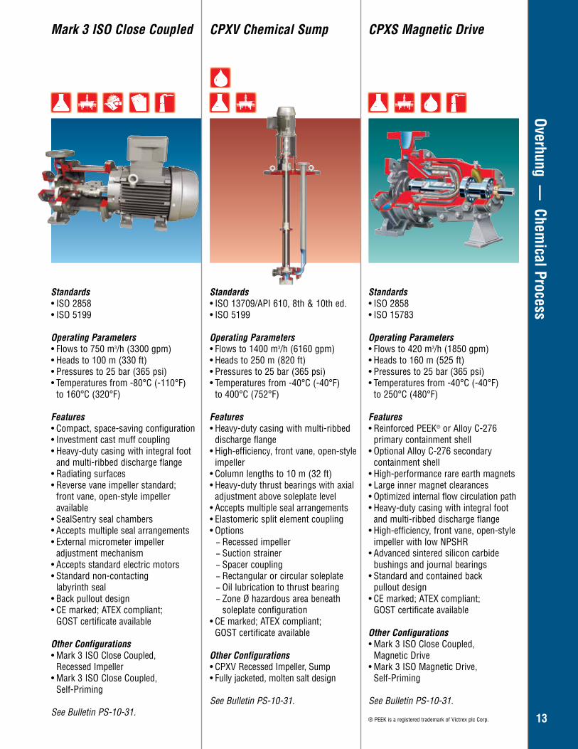
ical ProcessMark 3 ISO Close Coupled CPXV Chemical Sump CPXS Magnetic Drive
Standards• ISO 2858• ISO 5199
Operating Parameters• Flows to 750 m3/h (3300 gpm)• Heads to 100 m (330 ft)• Pressures to 25 bar (365 psi)• Temperatures from -80°C (-110°F)
to 160°C (320°F)
Features• Compact, space-saving configuration• Investment cast muff coupling• Heavy-duty casing with integral foot
and multi-ribbed discharge flange• Radiating surfaces• Reverse vane impeller standard;
front vane, open-style impeller available
• SealSentry seal chambers• Accepts multiple seal arrangements• External micrometer impeller
adjustment mechanism• Accepts standard electric motors• Standard non-contacting
labyrinth seal• Back pullout design• CE marked; ATEX compliant;
GOST certificate available
Other Configurations• Mark 3 ISO Close Coupled,
Recessed Impeller• Mark 3 ISO Close Coupled,
Self-Priming
See Bulletin PS-10-31.
Standards• ISO 2858• ISO 15783
Operating Parameters• Flows to 420 m3/h (1850 gpm)• Heads to 160 m (525 ft)• Pressures to 25 bar (365 psi)• Temperatures from -40°C (-40°F)
to 250°C (480°F)
Features• Reinforced PEEK® or Alloy C-276
primary containment shell• Optional Alloy C-276 secondary
containment shell • High-performance rare earth magnets• Large inner magnet clearances• Optimized internal flow circulation path• Heavy-duty casing with integral foot
and multi-ribbed discharge flange• High-efficiency, front vane, open-style
impeller with low NPSHR• Advanced sintered silicon carbide
bushings and journal bearings• Standard and contained back
pullout design• CE marked; ATEX compliant;
GOST certificate available
Other Configurations• Mark 3 ISO Close Coupled,
Magnetic Drive• Mark 3 ISO Magnetic Drive,
Self-Priming
See Bulletin PS-10-31.
® PEEK is a registered trademark of Victrex plc Corp.
Standards• ISO 13709/API 610, 8th & 10th ed.• ISO 5199
Operating Parameters• Flows to 1400 m3/h (6160 gpm)• Heads to 250 m (820 ft)• Pressures to 25 bar (365 psi)• Temperatures from -40°C (-40°F)
to 400°C (752°F)
Features• Heavy-duty casing with multi-ribbed
discharge flange• High-efficiency, front vane, open-style
impeller • Column lengths to 10 m (32 ft) • Heavy-duty thrust bearings with axial
adjustment above soleplate level• Accepts multiple seal arrangements• Elastomeric split element coupling• Options
− Recessed impeller − Suction strainer − Spacer coupling − Rectangular or circular soleplate − Oil lubrication to thrust bearing − Zone Ø hazardous area beneath soleplate configuration
• CE marked; ATEX compliant; GOST certificate available
Other Configurations• CPXV Recessed Impeller, Sump• Fully jacketed, molten salt design
See Bulletin PS-10-31.
14
Overhung — Chem
ical Process
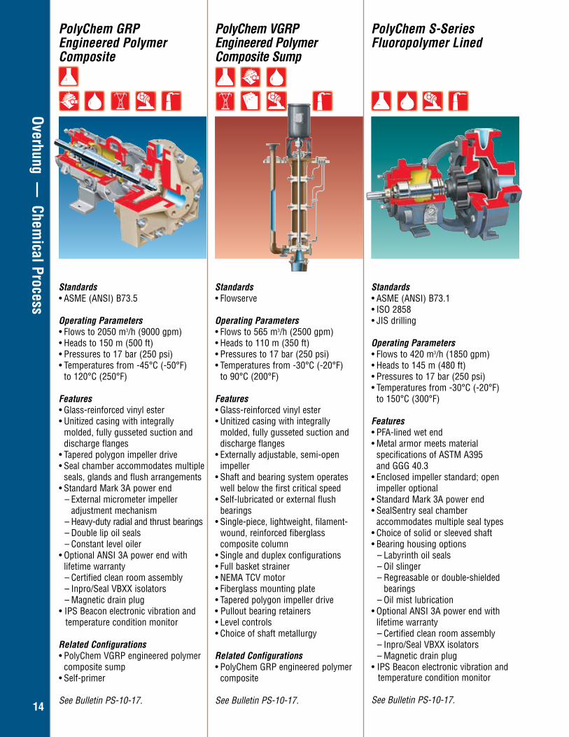
PolyChem GRP Engineered Polymer Composite
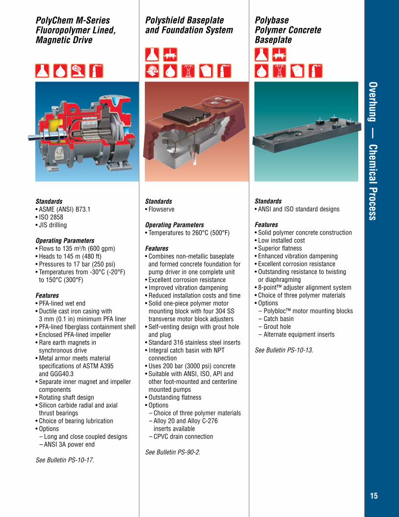
PolyChem VGRP Engineered Polymer Composite Sump
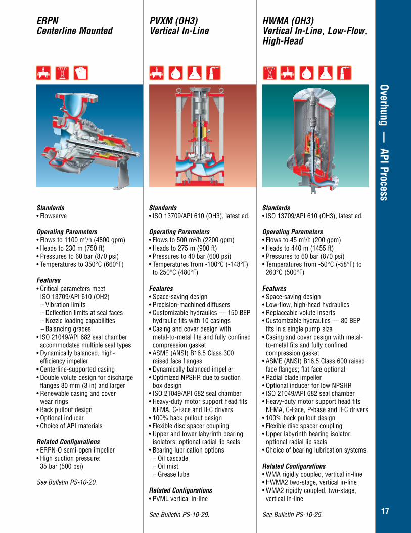
PolyChem S-Series Fluoropolymer Lined
Standards• ASME (ANSI) B73.5 Operating Parameters• Flows to 2050 m3/h (9000 gpm) • Heads to 150 m (500 ft) • Pressures to 17 bar (250 psi) • Temperatures from -45°C (-50°F)
to 120°C (250°F) Features• Glass-reinforced vinyl ester • Unitized casing with integrally
molded, fully gusseted suction and discharge flanges
• Tapered polygon impeller drive • Seal chamber accommodates multiple
seals, glands and flush arrangements• Standard Mark 3A power end
– External micrometer impeller adjustment mechanism
– Heavy-duty radial and thrust bearings– Double lip oil seals– Constant level oiler
• Optional ANSI 3A power end with lifetime warranty
– Certified clean room assembly – Inpro/Seal VBXX isolators – Magnetic drain plug
• IPS Beacon electronic vibration and temperature condition monitor
Related Configurations• PolyChem VGRP engineered polymer composite sump • Self-primer
See Bulletin PS-10-17.
Standards• Flowserve
Operating Parameters• Flows to 565 m3/h (2500 gpm) • Heads to 110 m (350 ft) • Pressures to 17 bar (250 psi) • Temperatures from -30°C (-20°F)
to 90°C (200°F) Features• Glass-reinforced vinyl ester • Unitized casing with integrally
molded, fully gusseted suction and discharge flanges
• Externally adjustable, semi-open impeller
• Shaft and bearing system operates well below the first critical speed
• Self-lubricated or external flush bearings
• Single-piece, lightweight, filament-wound, reinforced fiberglass composite column
• Single and duplex configurations • Full basket strainer • NEMA TCV motor • Fiberglass mounting plate • Tapered polygon impeller drive • Pullout bearing retainers • Level controls • Choice of shaft metallurgy
Related Configurations• PolyChem GRP engineered polymer
composite
See Bulletin PS-10-17.
Standards• ASME (ANSI) B73.1• ISO 2858• JIS drilling
Operating Parameters• Flows to 420 m3/h (1850 gpm) • Heads to 145 m (480 ft) • Pressures to 17 bar (250 psi) • Temperatures from -30°C (-20°F)
to 150°C (300°F)
Features • PFA-lined wet end • Metal armor meets material
specifications of ASTM A395 and GGG 40.3• Enclosed impeller standard; open
impeller optional• Standard Mark 3A power end • SealSentry seal chamber
accommodates multiple seal types • Choice of solid or sleeved shaft • Bearing housing options
– Labyrinth oil seals – Oil slinger – Regreasable or double-shielded
bearings – Oil mist lubrication
• Optional ANSI 3A power end with lifetime warranty
– Certified clean room assembly – Inpro/Seal VBXX isolators – Magnetic drain plug
• IPS Beacon electronic vibration and temperature condition monitor
See Bulletin PS-10-17.
15
Overhung — Chem
ical ProcessPolyshield Baseplate and Foundation System
Polybase Polymer Concrete Baseplate
Standards• Flowserve
Operating Parameters• Temperatures to 260°C (500°F)
Features• Combines non-metallic baseplate
and formed concrete foundation for pump driver in one complete unit
• Excellent corrosion resistance• Improved vibration dampening• Reduced installation costs and time• Solid one-piece polymer motor
mounting block with four 304 SS transverse motor block adjusters
• Self-venting design with grout hole and plug
• Standard 316 stainless steel inserts• Integral catch basin with NPT connection• Uses 200 bar (3000 psi) concrete• Suitable with ANSI, ISO, API and
other foot-mounted and centerline mounted pumps
• Outstanding flatness• Options
– Choice of three polymer materials– Alloy 20 and Alloy C-276
inserts available– CPVC drain connection
See Bulletin PS-90-2.
Standards• ANSI and ISO standard designs
Features• Solid polymer concrete construction• Low installed cost• Superior flatness• Enhanced vibration dampening• Excellent corrosion resistance• Outstanding resistance to twisting
or diaphragming• 8-point™ adjuster alignment system• Choice of three polymer materials• Options
– Polybloc™ motor mounting blocks – Catch basin– Grout hole– Alternate equipment inserts
See Bulletin PS-10-13.
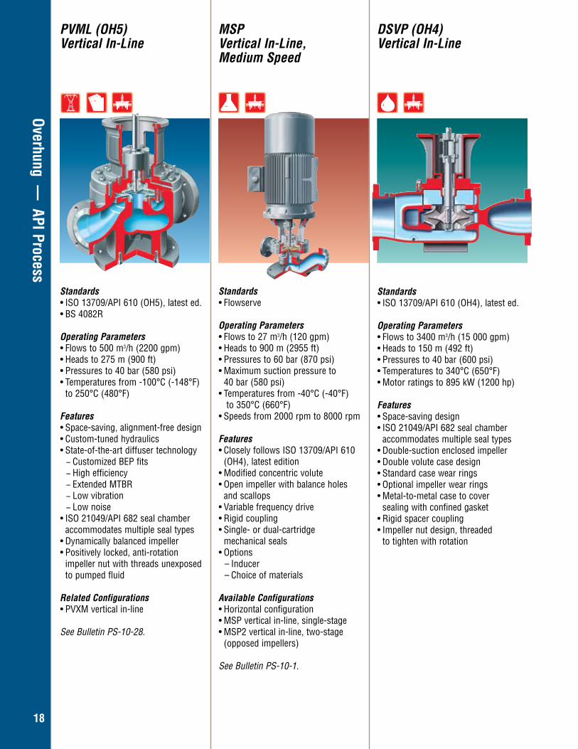
PolyChem M-Series Fluoropolymer Lined, Magnetic Drive
Standards• ASME (ANSI) B73.1• ISO 2858• JIS drilling
Operating Parameters• Flows to 135 m3/h (600 gpm) • Heads to 145 m (480 ft) • Pressures to 17 bar (250 psi) • Temperatures from -30°C (-20°F)
to 150°C (300°F)
Features • PFA-lined wet end • Ductile cast iron casing with 3 mm (0.1 in) minimum PFA liner • PFA-lined fiberglass containment shell• Enclosed PFA-lined impeller• Rare earth magnets in synchronous drive• Metal armor meets material
specifications of ASTM A395 and GGG40.3
• Separate inner magnet and impeller components
• Rotating shaft design • Silicon carbide radial and axial thrust bearings • Choice of bearing lubrication• Options
– Long and close coupled designs– ANSI 3A power end
See Bulletin PS-10-17.

16
Overhung — API Process
Standards • ISO 13709/API 610 (OH2), latest ed.
Operating Parameters• Flows to 2000 m3/h (8800 gpm) • Heads to 350 m (1100 ft) • Pressures to 80 bar (1160 psi) • Temperatures from -160°C (-250°F) to 450°C (842°F)
Features• Centerline-supported casing • Nozzle loading capability beyond ISO 13709/API 610 requirements• Dynamically balanced impeller • Rugged shaft design • ISO 21049/API 682 seal chamber
accommodates multiple seal types• Choice of bearings
– Standard single row, deep groove, radial bearing and duplex, single row 40° angular contact thrust bearings
– Special bearing arrangements for high suction pressures
• Bearing lubrication and cooling options – Oil mist and oil purge– Fan cooling – Finned cooling insert
Related Configurations • HPXT centerline mounted, top suction• HPXH centerline mounted, high
suction pressure• HPXSL centerline mounted, slurry• HPXIND centerline mounted, inducer• HPXCC centerline mounted,
coke crusher
See Bulletin PS-10-5.
Standards • ISO 13709/API 610 (OH2), latest ed.
Operating Parameters• Flows to 30 m3/h (130 gpm) • Heads to 280 m (920 ft) • Pressures to 80 bar (1160 psi) • Temperatures from -160°C (-250°F) to 450°C (842°F)
Features• Low-flow, high-head design • Replaceable volute inserts• High-efficiency radial blade impeller• Full interchangeability with HPX bear-
ing assembly and mechanical seals• Choice of bearings
– Standard single row, deep groove, radial bearing and duplex, single row 40° angular contact thrust bearings
– Special bearing arrangements for high suction pressures
• ISO 21049/API 682 seal chamber accommodates multiple seal types
• Bearing lubrication and cooling options – Oil mist and oil purge – Fan cooling – Finned cooling insert
• Optional inducer
Related Configurations • HPX centerline mounted
See Bulletin PSS-10-5.1.
Standards • ISO 13709/API 610 (OH2), latest ed.
Operating Parameters• Flows to 900 m3/h (4000 gpm) • Heads to 400 m (1300 ft) • Pressures to 40 bar (600 psi) • Temperatures from -160°C (-250°F)
to 450°C (842°F) • Motor sizes to 110 kW (150 hp)
Features• Centerline-supported, end
suction casing• Custom-tuned hydraulics• Multi-channel diffuser technology
− Customized BEP fits − High efficiency − Extended MTBR − Low vibration − Low noise
• Low shaft deflection at any flow • ISO 21049/API 682 seal chamber
accommodates multiple seal types including dual pressurized, unpressurized and gas
• Bearing housing cooling options – Air fan – Water jacket
• Replaceable diffusers• Available boron diffusion
surface treatment
Other Configurations • Top suction nozzle
See Bulletin PSS-10-5.2.
HPX (OH2) Centerline Mounted
HPXM (OH2) Centerline Mounted, Low-Flow
PHL (OH2) Centerline Mounted
17
Overhung — API Process
Standards• Flowserve
Operating Parameters• Flows to 1100 m3/h (4800 gpm) • Heads to 230 m (750 ft) • Pressures to 60 bar (870 psi) • Temperatures to 350°C (660°F)
Features • Critical parameters meet
ISO 13709/API 610 (OH2)– Vibration limits– Deflection limits at seal faces– Nozzle loading capabilities– Balancing grades
• ISO 21049/API 682 seal chamber accommodates multiple seal types
• Dynamically balanced, high- efficiency impeller
• Centerline-supported casing • Double volute design for discharge
flanges 80 mm (3 in) and larger • Renewable casing and cover
wear rings• Back pullout design • Optional inducer • Choice of API materials
Related Configurations• ERPN-O semi-open impeller• High suction pressure:
35 bar (500 psi)
See Bulletin PS-10-20.
Standards• ISO 13709/API 610 (OH3), latest ed.
Operating Parameters• Flows to 500 m3/h (2200 gpm)• Heads to 275 m (900 ft)• Pressures to 40 bar (600 psi)• Temperatures from -100°C (-148°F)
to 250°C (480°F)
Features • Space-saving design• Precision-machined diffusers• Customizable hydraulics — 150 BEP
hydraulic fits with 10 casings• Casing and cover design with
metal-to-metal fits and fully confined compression gasket
• ASME (ANSI) B16.5 Class 300 raised face flanges
• Dynamically balanced impeller• Optimized NPSHR due to suction
box design• ISO 21049/API 682 seal chamber• Heavy-duty motor support head fits
NEMA, C-Face and IEC drivers• 100% back pullout design• Flexible disc spacer coupling• Upper and lower labyrinth bearing
isolators; optional radial lip seals• Bearing lubrication options
− Oil cascade − Oil mist − Grease lube
Related Configurations• PVML vertical in-line
See Bulletin PS-10-29.
Standards• ISO 13709/API 610 (OH3), latest ed.
Operating Parameters• Flows to 45 m3/h (200 gpm)• Heads to 440 m (1455 ft)• Pressures to 60 bar (870 psi)• Temperatures from -50°C (-58°F) to
260°C (500°F)
Features • Space-saving design• Low-flow, high-head hydraulics• Replaceable volute inserts• Customizable hydraulics — 80 BEP
fits in a single pump size• Casing and cover design with metal-
to-metal fits and fully confined compression gasket
• ASME (ANSI) B16.5 Class 600 raised face flanges; flat face optional
• Radial blade impeller• Optional inducer for low NPSHR• ISO 21049/API 682 seal chamber• Heavy-duty motor support head fits
NEMA, C-Face, P-base and IEC drivers• 100% back pullout design• Flexible disc spacer coupling• Upper labyrinth bearing isolator;
optional radial lip seals• Choice of bearing lubrication systems
Related Configurations• WMA rigidly coupled, vertical in-line• HWMA2 two-stage, vertical in-line• WMA2 rigidly coupled, two-stage,
vertical in-line
See Bulletin PS-10-25.
ERPN Centerline Mounted
PVXM (OH3) Vertical In-Line
HWMA (OH3)Vertical In-Line, Low-Flow, High-Head
18
Overhung — API Process
Standards• ISO 13709/API 610 (OH5), latest ed.• BS 4082R
Operating Parameters• Flows to 500 m3/h (2200 gpm) • Heads to 275 m (900 ft) • Pressures to 40 bar (580 psi) • Temperatures from -100°C (-148°F)
to 250°C (480°F)
Features• Space-saving, alignment-free design • Custom-tuned hydraulics • State-of-the-art diffuser technology
− Customized BEP fits − High efficiency − Extended MTBR − Low vibration − Low noise
• ISO 21049/API 682 seal chamber accommodates multiple seal types
• Dynamically balanced impeller • Positively locked, anti-rotation
impeller nut with threads unexposed to pumped fluid
Related Configurations • PVXM vertical in-line
See Bulletin PS-10-28.
PVML (OH5)Vertical In-Line
Standards• Flowserve
Operating Parameters• Flows to 27 m3/h (120 gpm) • Heads to 900 m (2955 ft) • Pressures to 60 bar (870 psi) • Maximum suction pressure to 40 bar (580 psi) • Temperatures from -40°C (-40°F) to 350°C (660°F) • Speeds from 2000 rpm to 8000 rpm
Features• Closely follows ISO 13709/API 610
(OH4), latest edition• Modified concentric volute • Open impeller with balance holes
and scallops • Variable frequency drive • Rigid coupling • Single- or dual-cartridge
mechanical seals • Options
– Inducer– Choice of materials
Available Configurations • Horizontal configuration• MSP vertical in-line, single-stage• MSP2 vertical in-line, two-stage
(opposed impellers)
See Bulletin PS-10-1.
MSPVertical In-Line, Medium Speed
DSVP (OH4)Vertical In-Line
Standards• ISO 13709/API 610 (OH4), latest ed.
Operating Parameters• Flows to 3400 m3/h (15 000 gpm) • Heads to 150 m (492 ft) • Pressures to 40 bar (600 psi) • Temperatures to 340°C (650°F)• Motor ratings to 895 kW (1200 hp)
Features• Space-saving design• ISO 21049/API 682 seal chamber
accommodates multiple seal types• Double-suction enclosed impeller • Double volute case design • Standard case wear rings • Optional impeller wear rings • Metal-to-metal case to cover
sealing with confined gasket • Rigid spacer coupling • Impeller nut design, threaded
to tighten with rotation
19
Overhung — Slurry and Solids Handling
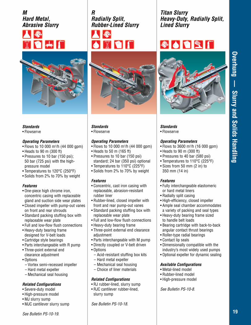
Standards• Flowserve
Operating Parameters• Flows to 10 000 m3/h (44 000 gpm) • Heads to 90 m (300 ft) • Pressures to 10 bar (150 psi);
50 bar (725 psi) with the high- pressure model
• Temperatures to 120°C (250°F) • Solids from 2% to 70% by weight Features • One-piece high chrome iron,
concentric casing with replaceable gland and suction side wear plates
• Closed impeller with pump-out vanes on front and rear shrouds
• Standard packing stuffing box with replaceable wear plate
• Full and low-flow flush connections• Heavy-duty bearing frame
designed for V-belt loads• Cartridge style bearings • Parts interchangeable with R pump • Three-point external end
clearance adjustment • Options
– Vortex semi-recessed impeller – Hard metal expeller – Mechanical seal housing
Related Configurations • Severe-duty model• High-pressure model• MJ slurry sump• MJC cantilever slurry sump
See Bulletin PS-10-19.
M Hard Metal, Abrasive Slurry
Standards• Flowserve
Operating Parameters• Flows to 10 000 m3/h (44 000 gpm) • Heads to 50 m (165 ft) • Pressures to 10 bar (150 psi)
standard; 24 bar (350 psi) optional • Temperatures to 110°C (225°F) • Solids from 2% to 70% by weight
Features• Concentric, cast iron casing with
replaceable, abrasion-resistant rubber liner
• Rubber-lined, closed impeller with front and rear pump-out vanes
• Standard packing stuffing box with replaceable wear plate
• Full and low-flow flush connections• Heavy-duty bearing frame• Three-point external end clearance
adjustment • Parts interchangeable with M pump • Directly coupled or V-belt driven • Options
– Acid-resistant stuffing box kits– Hard metal expeller – Mechanical seal housing – Choice of liner materials
Related Configurations • RJ rubber-lined, slurry sump• RJC cantilever rubber-lined, slurry sump
See Bulletin PS-10-18.
R Radially Split, Rubber-Lined Slurry
Standards• Flowserve
Operating Parameters• Flows to 3600 m3/h (16 000 gpm) • Heads to 90 m (300 ft)• Pressures to 40 bar (580 psi)• Temperatures to 110°C (225°F) • Sizes from 50 mm (2 in) to
350 mm (14 in)
Features• Fully interchangeable elastomeric
or hard metal liners • Radially split casing• High-efficiency, closed impeller • Ample seal chamber accommodates
a variety of packing and seal types• Heavy-duty bearing frame sized
to handle belt loads • Bearing cartridge with back-to-back
angular contact thrust bearings • Roller-type radial bearings • Contact lip seals• Dimensionally compatible with the
industry’s most widely used pumps• Optional expeller for dynamic sealing
Available Configurations • Metal-lined model• Rubber-lined model• High-pressure model
See Bulletin PS-10-8.
Titan Slurry Heavy-Duty, Radially Split, Lined Slurry
20
Overhung — Slurry and Solids Handling
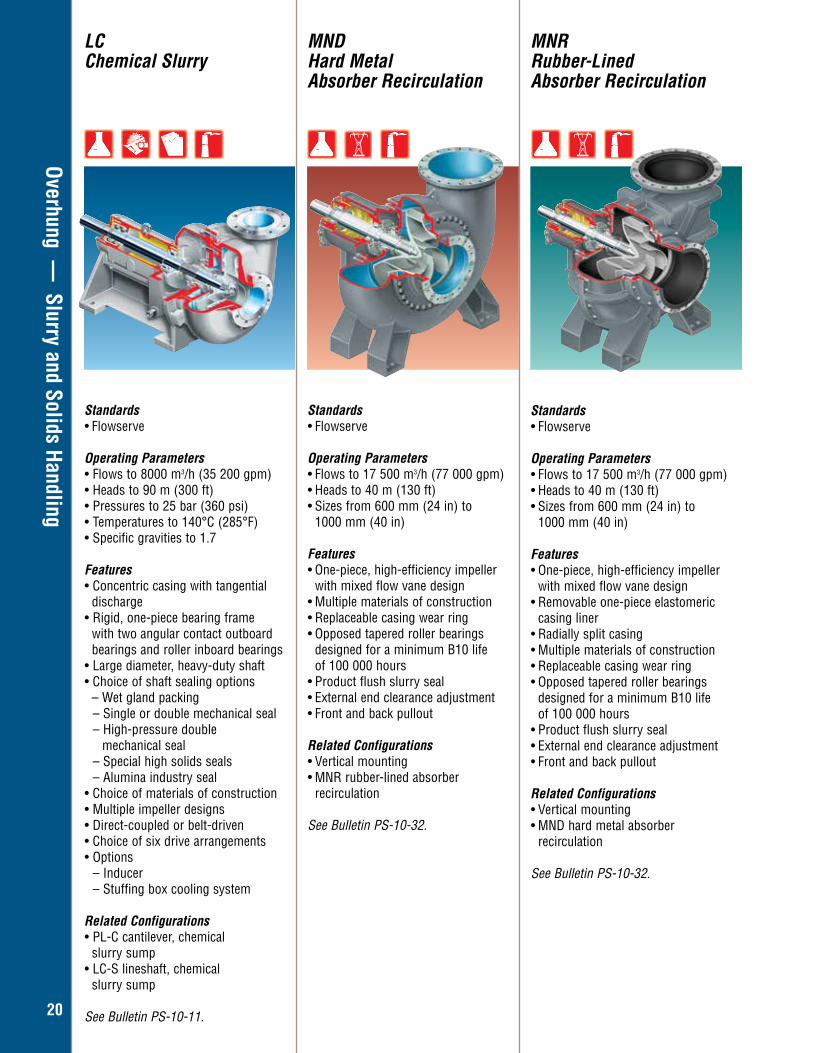
Standards• Flowserve
Operating Parameters• Flows to 17 500 m3/h (77 000 gpm) • Heads to 40 m (130 ft) • Sizes from 600 mm (24 in) to 1000 mm (40 in)
Features • One-piece, high-efficiency impeller with mixed flow vane design • Multiple materials of construction• Replaceable casing wear ring • Opposed tapered roller bearings
designed for a minimum B10 life of 100 000 hours• Product flush slurry seal • External end clearance adjustment • Front and back pullout
Related Configurations• Vertical mounting • MNR rubber-lined absorber
recirculation
See Bulletin PS-10-32.
MNDHard Metal Absorber Recirculation
Standards• Flowserve
Operating Parameters• Flows to 8000 m3/h (35 200 gpm)• Heads to 90 m (300 ft)• Pressures to 25 bar (360 psi)• Temperatures to 140°C (285°F)• Specific gravities to 1.7
Features• Concentric casing with tangential discharge• Rigid, one-piece bearing frame
with two angular contact outboard bearings and roller inboard bearings
• Large diameter, heavy-duty shaft• Choice of shaft sealing options – Wet gland packing
– Single or double mechanical seal– High-pressure double
mechanical seal– Special high solids seals – Alumina industry seal
• Choice of materials of construction• Multiple impeller designs • Direct-coupled or belt-driven• Choice of six drive arrangements• Options
– Inducer– Stuffing box cooling system
Related Configurations• PL-C cantilever, chemical
slurry sump• LC-S lineshaft, chemical
slurry sump
See Bulletin PS-10-11.
LCChemical Slurry
Standards• Flowserve
Operating Parameters• Flows to 17 500 m3/h (77 000 gpm) • Heads to 40 m (130 ft) • Sizes from 600 mm (24 in) to 1000 mm (40 in)
Features • One-piece, high-efficiency impeller
with mixed flow vane design • Removable one-piece elastomeric
casing liner• Radially split casing• Multiple materials of construction• Replaceable casing wear ring • Opposed tapered roller bearings
designed for a minimum B10 life of 100 000 hours• Product flush slurry seal • External end clearance adjustment • Front and back pullout
Related Configurations• Vertical mounting • MND hard metal absorber
recirculation
See Bulletin PS-10-32.
MNRRubber-LinedAbsorber Recirculation
21
Overhung — Slurry and Solids Handling
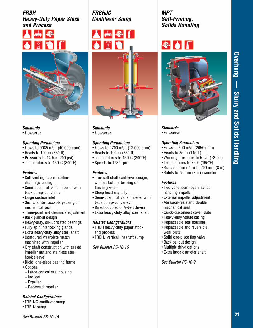
Standards• Flowserve
Operating Parameters• Flows to 2700 m3/h (12 000 gpm) • Heads to 100 m (330 ft) • Temperatures to 150°C (300°F) • Speeds to 1780 rpm Features• True stiff shaft cantilever design,
without bottom bearing or flushing water
• Steep head capacity • Semi-open, full vane impeller with
back pump-out vanes • Direct coupled or V-belt driven• Extra heavy-duty alloy steel shaft
Related Configurations• FRBH heavy-duty paper stock
and process• FRBHJ vertical lineshaft sump
See Bulletin PS-10-16.
Standards• Flowserve
Operating Parameters• Flows to 9085 m3/h (40 000 gpm) • Heads to 100 m (330 ft) • Pressures to 14 bar (200 psi)• Temperatures to 150°C (300°F) Features• Self-venting, top centerline discharge casing • Semi-open, full vane impeller with
back pump-out vanes • Large suction inlet • Seal chamber accepts packing or
mechanical seal• Three-point end clearance adjustment • Back pullout design • Heavy-duty, oil-lubricated bearings • Fully split interlocking glands • Extra heavy-duty alloy steel shaft• Contoured wearplate match machined with impeller• Dry shaft construction with sealed
impeller nut and stainless steel hook sleeve
• Rigid, one-piece bearing frame• Options
– Large conical seal housing– Inducer– Expeller– Recessed impeller
Related Configurations• FRBHJC cantilever sump• FRBHJ sump
See Bulletin PS-10-16.
FRBHJCCantilever Sump
MPTSelf-Priming, Solids Handling
FRBHHeavy-Duty Paper Stock and Process
Standards• Flowserve
Operating Parameters• Flows to 600 m3/h (2650 gpm)• Heads to 35 m (115 ft)• Working pressures to 5 bar (72 psi)• Temperatures to 75°C (165°F)• Sizes 50 mm (2 in) to 200 mm (8 in)• Solids to 75 mm (3 in) diameter
Features• Two-vane, semi-open, solids
handling impeller• External impeller adjustment• Abrasion-resistant, double
mechanical seal• Quick-disconnect cover plate• Heavy-duty volute casing• Replaceable seal housing• Replaceable and reversible
wear plate• Solid one-piece flap valve• Back pullout design• Multiple drive options• Extra large diameter shaft
See Bulletin PS-10-9.

22
Overhung — Slurry and Solids Handling
Standards• Flowserve
Operating Parameters• Flows to 4545 m3/h (20 000 gpm) • Heads to 90 m (300 ft) • Temperatures to 40°C (104°F)• Discharge sizes from 80 mm (3 in)
to 500 mm (20 in) • Motor ratings to 224 kW (300 hp) • Solids handling to 80 mm (3 in)
diameter spherical
Features • High-efficiency hydraulics • EPACT-rated motor • Spike-resistant windings • Class H insulation system • Dynamically balanced shaft and rotor • Mounting options
– Wet-pit – Dry-pit – Transportable
Available Configurations • MSX Series 1: sizes from 75 mm (3 in) to 150 mm (6 in)• MSX Series 2/3: sizes to 500 mm (20 in)
See Bulletin PS-50-2.
MSXSolids Handling, Submersible
Standards• Flowserve
Operating Parameters• Flows to 45 500 m3/h (200 000 gpm) • Heads to 90 m (300 ft) • Sizes to 1800 mm (72 in)
Features• Variety of nozzle position options• Direct or independent motor mounting• Minimal shaft deflection• Oversized shaft and reduced overhang • Hardened chrome steel wear rings • Seal chamber accommodates packing
or mechanical seals • Adjustable wear ring clearance • Shaft sleeve options
– 316 stainless steel – Hardened chrome steel
• Bearing housing features – Tapered roller bearings – Integral jacking bolts for wear
ring adjustment– Accessible lubrication points
Available Configurations • MN horizontal, end suction• MNF vertical, bottom suction, direct
connected motor • MNZ vertical, bottom suction, motor
on separate floor • MNC vertical with base elbow, direct
connected motor • MNV vertical with base elbow, motor
on separate floor (shown)
See Bulletin PS-10-4.
MNLarge Capacity, Solids Handling
Standards• Flowserve
Operating Parameters• Flows to 2275 m3/h (10 000 gpm) • Heads to 90 m (300 ft) • Sizes to 400 mm (16 in)
Features• Variety of nozzle position options • Direct or independent motor mounting• Minimal shaft deflection• Oversized shaft and reduced overhang • Hardened chrome steel wear rings • Seal chamber accommodates packing
or mechanical seals• Adjustable impeller clearance• Shaft sleeve options
– 316 stainless steel – Hardened chrome steel
• Bearing housing features – Ball or tapered roller bearings – Integral jacking bolts for wear ring adjustment – Accessible lubrication points
Available Configurations • MF horizontal, end suction• MFV vertical with motor on separate floor (shown)• MFC vertical with direct connected
motor
See Bulletin PS-10-3.
MFSolids Handling
23
Overhung — Industrial Process
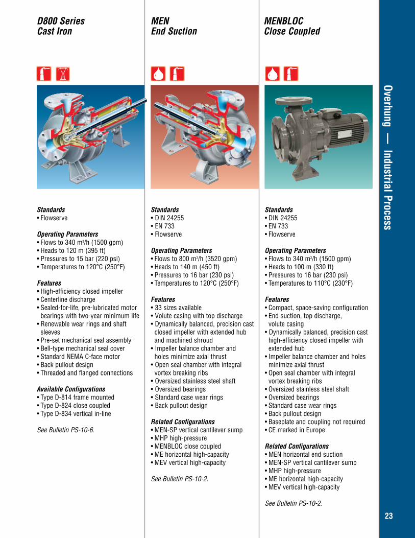
Standards• Flowserve
Operating Parameters• Flows to 340 m3/h (1500 gpm) • Heads to 120 m (395 ft) • Pressures to 15 bar (220 psi) • Temperatures to 120°C (250°F)
Features • High-efficiency closed impeller• Centerline discharge• Sealed-for-life, pre-lubricated motor
bearings with two-year minimum life• Renewable wear rings and shaft
sleeves • Pre-set mechanical seal assembly • Bell-type mechanical seal cover• Standard NEMA C-face motor • Back pullout design • Threaded and flanged connections
Available Configurations • Type D-814 frame mounted • Type D-824 close coupled • Type D-834 vertical in-line
See Bulletin PS-10-6.
Standards• DIN 24255 • EN 733• Flowserve
Operating Parameters• Flows to 800 m3/h (3520 gpm)• Heads to 140 m (450 ft)• Pressures to 16 bar (230 psi)• Temperatures to 120°C (250°F)
Features• 33 sizes available• Volute casing with top discharge• Dynamically balanced, precision cast
closed impeller with extended hub and machined shroud
• Impeller balance chamber and holes minimize axial thrust
• Open seal chamber with integral vortex breaking ribs
• Oversized stainless steel shaft• Oversized bearings • Standard case wear rings• Back pullout design
Related Configurations• MEN-SP vertical cantilever sump• MHP high-pressure• MENBLOC close coupled• ME horizontal high-capacity• MEV vertical high-capacity
See Bulletin PS-10-2.
Standards• DIN 24255• EN 733• Flowserve
Operating Parameters• Flows to 340 m3/h (1500 gpm)• Heads to 100 m (330 ft)• Pressures to 16 bar (230 psi)• Temperatures to 110°C (230°F)
Features• Compact, space-saving configuration• End suction, top discharge,
volute casing• Dynamically balanced, precision cast
high-efficiency closed impeller with extended hub
• Impeller balance chamber and holes minimize axial thrust
• Open seal chamber with integral vortex breaking ribs
• Oversized stainless steel shaft• Oversized bearings• Standard case wear rings• Back pullout design• Baseplate and coupling not required• CE marked in Europe
Related Configurations• MEN horizontal end suction• MEN-SP vertical cantilever sump• MHP high-pressure • ME horizontal high-capacity• MEV vertical high-capacity
See Bulletin PS-10-2.
D800 SeriesCast Iron
MENEnd Suction
MENBLOCClose Coupled
24
Overhung — Industrial Process
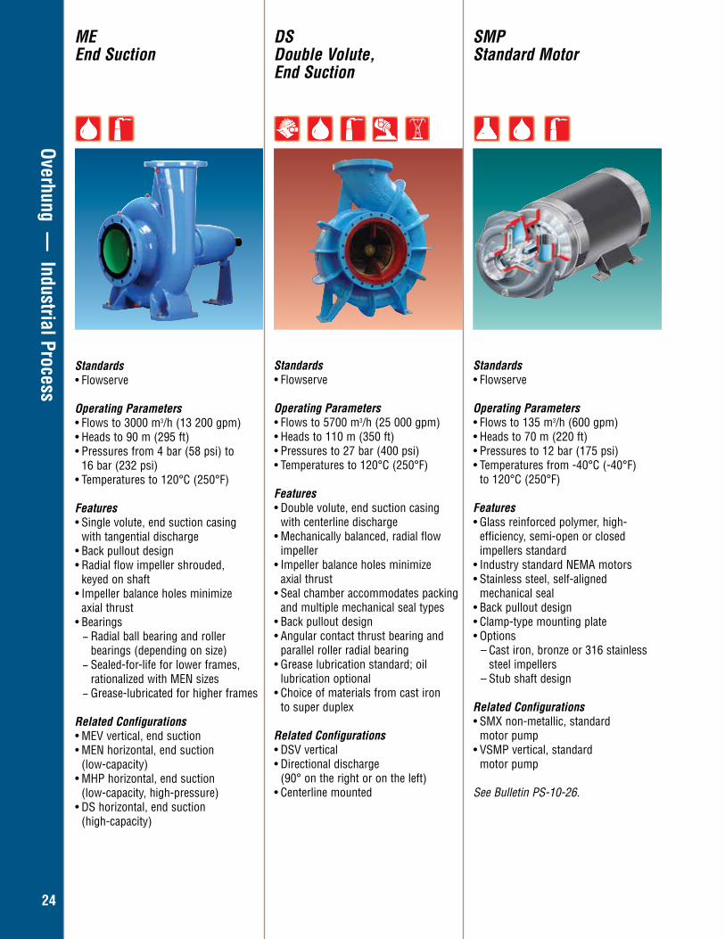
Standards• Flowserve
Operating Parameters• Flows to 5700 m3/h (25 000 gpm)• Heads to 110 m (350 ft)• Pressures to 27 bar (400 psi)• Temperatures to 120°C (250°F)
Features• Double volute, end suction casing
with centerline discharge• Mechanically balanced, radial flow
impeller• Impeller balance holes minimize
axial thrust• Seal chamber accommodates packing
and multiple mechanical seal types• Back pullout design• Angular contact thrust bearing and
parallel roller radial bearing • Grease lubrication standard; oil
lubrication optional• Choice of materials from cast iron
to super duplex
Related Configurations• DSV vertical • Directional discharge
(90° on the right or on the left)• Centerline mounted
Standards• Flowserve
Operating Parameters• Flows to 135 m3/h (600 gpm)• Heads to 70 m (220 ft)• Pressures to 12 bar (175 psi)• Temperatures from -40°C (-40°F)
to 120°C (250°F)
Features• Glass reinforced polymer, high-
efficiency, semi-open or closed impellers standard
• Industry standard NEMA motors • Stainless steel, self-aligned mechanical seal• Back pullout design• Clamp-type mounting plate• Options
– Cast iron, bronze or 316 stainless steel impellers
– Stub shaft design
Related Configurations• SMX non-metallic, standard
motor pump• VSMP vertical, standard
motor pump
See Bulletin PS-10-26.
SMPStandard Motor
DSDouble Volute, End Suction
MEEnd Suction
Standards• Flowserve
Operating Parameters• Flows to 3000 m3/h (13 200 gpm)• Heads to 90 m (295 ft)• Pressures from 4 bar (58 psi) to
16 bar (232 psi)• Temperatures to 120°C (250°F)
Features• Single volute, end suction casing
with tangential discharge• Back pullout design• Radial flow impeller shrouded,
keyed on shaft • Impeller balance holes minimize
axial thrust• Bearings
− Radial ball bearing and roller bearings (depending on size) − Sealed-for-life for lower frames, rationalized with MEN sizes − Grease-lubricated for higher frames
Related Configurations• MEV vertical, end suction• MEN horizontal, end suction
(low-capacity)• MHP horizontal, end suction
(low-capacity, high-pressure)• DS horizontal, end suction
(high-capacity)
25
Overhung — Industrial Process
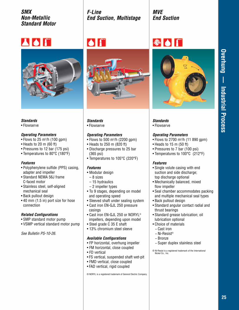
Standards• Flowserve
Operating Parameters• Flows to 500 m3/h (2200 gpm)• Heads to 250 m (820 ft)• Discharge pressures to 25 bar (365 psi)• Temperatures to 105°C (220°F)
Features• Modular design
– 8 sizes– 15 hydraulics– 2 impeller types
• To 9 stages, depending on model and operating speed• Sleeved shaft under sealing system• Cast iron EN-GJL 250 pressure casings• Cast iron EN-GJL 250 or NORYL®
impellers, depending upon model• Steel grade C 35 E shaft• 13% chromium steel sleeve
Available Configurations• FP horizontal, overhung impeller • FM horizontal, close coupled • FD vertical• FS vertical, suspended shaft wet-pit• FMD vertical, close coupled• FAD vertical, rigid coupled
® NORYL is a registered trademark of General Electric Company.
F-LineEnd Suction, Multistage
Standards• Flowserve
Operating Parameters• Flows to 25 m3/h (100 gpm)• Heads to 20 m (60 ft)• Pressures to 12 bar (175 psi)• Temperatures to 80°C (180°F)
Features• Polyphenylene sulfide (PPS) casing,
adapter and impeller • Standard NEMA 56J frame
C-faced motor• Stainless steel, self-aligned mechanical seal• Back pullout design• 40 mm (1.5 in) port size for hose connection
Related Configurations• SMP standard motor pump• VSMP vertical standard motor pump
See Bulletin PS-10-26.
SMXNon-Metallic Standard Motor
MVEEnd Suction
Standards• Flowserve
Operating Parameters• Flows to 2700 m3/h (11 890 gpm)• Heads to 15 m (50 ft)• Pressures to 7 bar (100 psi)• Temperatures to 100°C (212°F)
Features• Single volute casing with end
suction and side discharge; top discharge optional
• Mechanically balanced, mixed flow impeller
• Seal chamber accommodates packing and multiple mechanical seal types
• Back pullout design• Standard angular contact radial and
thrust bearings• Standard grease lubrication; oil
lubrication optional• Choice of materials
− Cast iron − Ni-Resist®
− Bronze − Super duplex stainless steel
® Ni-Resist is a registered trademark of the International Nickel Co., Inc.
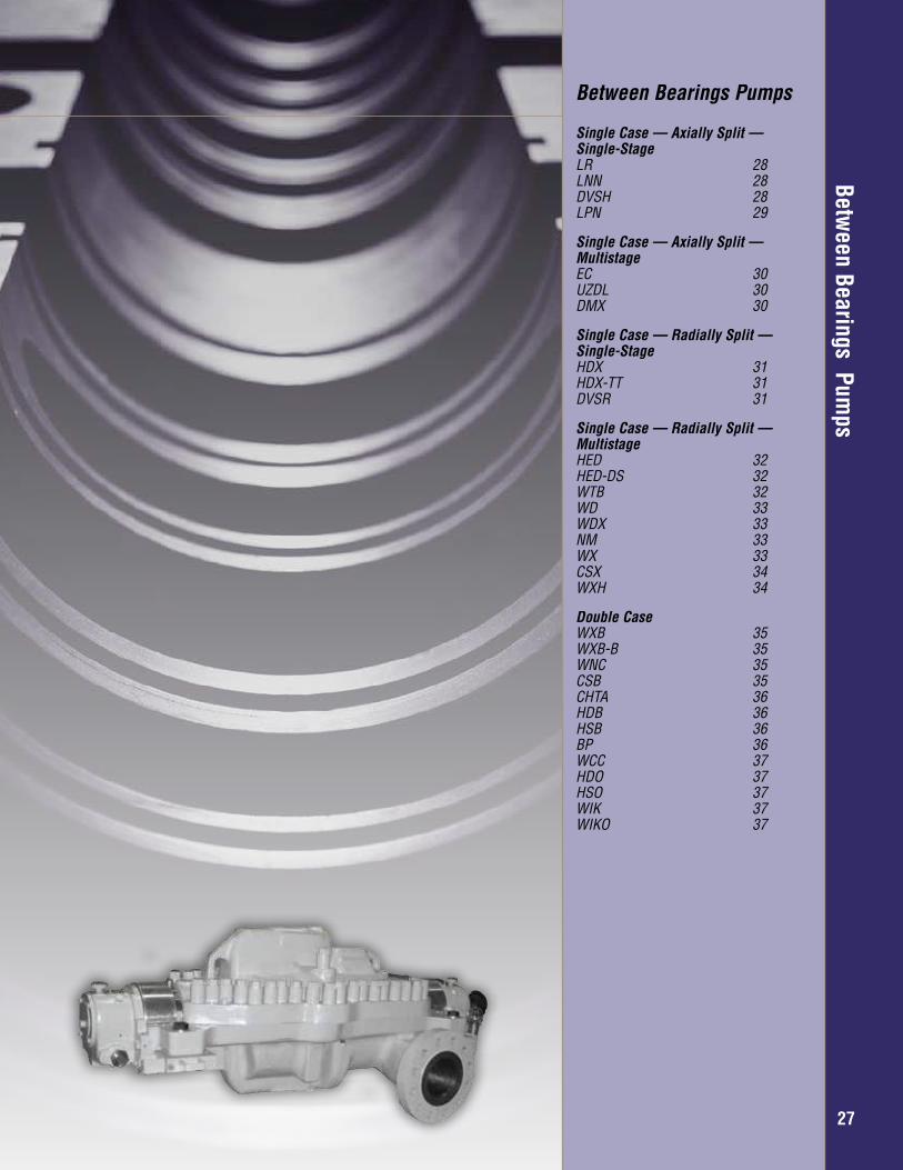
Between Bearings Pum
psBetween Bearings Pumps
Single Case — Axially Split — Single-StageLR 28LNN 28DVSH 28LPN 29
Single Case — Axially Split — MultistageEC 30UZDL 30DMX 30
Single Case — Radially Split — Single-StageHDX 31HDX-TT 31DVSR 31
Single Case — Radially Split — MultistageHED 32HED-DS 32WTB 32WD 33WDX 33NM 33WX 33CSX 34WXH 34
Double CaseWXB 35WXB-B 35WNC 35CSB 35CHTA 36HDB 36HSB 36BP 36WCC 37HDO 37HSO 37WIK 37WIKO 37
27
Between Bearings Pum
ps
Overhung – General Industry
2828
Between Bearings —
Single Case — Axially Split —
Single Stage
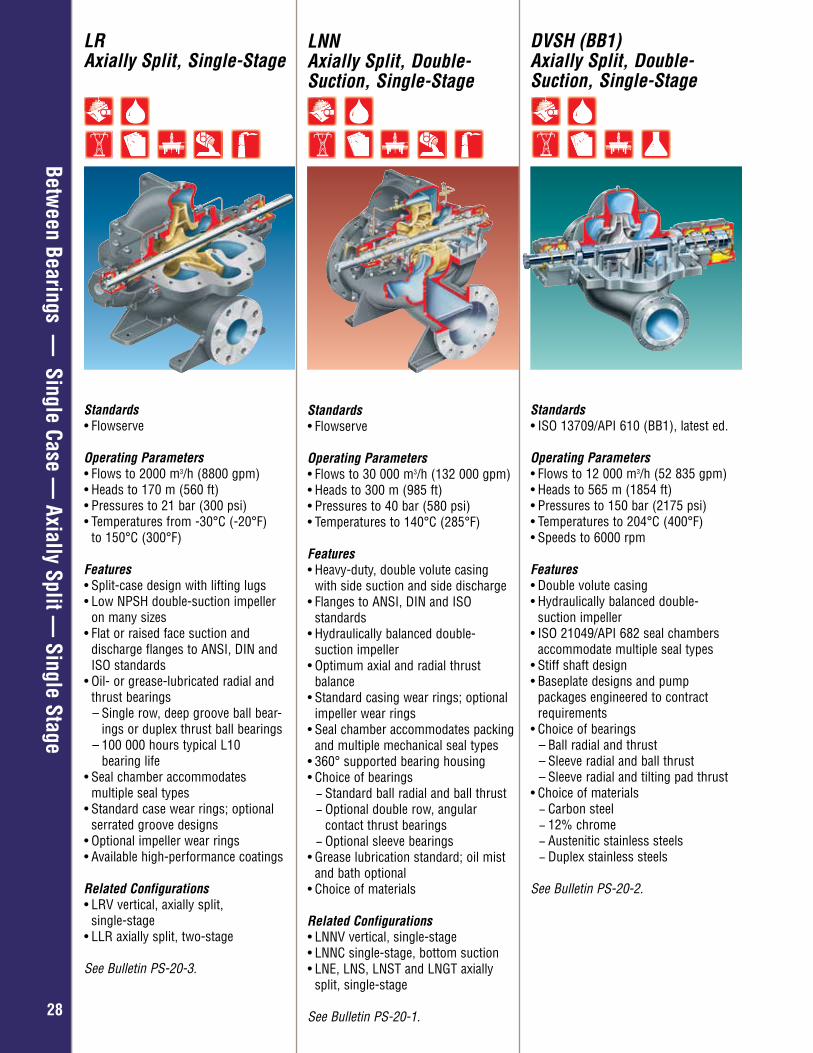
LRAxially Split, Single-Stage
Standards• Flowserve
Operating Parameters• Flows to 2000 m3/h (8800 gpm) • Heads to 170 m (560 ft) • Pressures to 21 bar (300 psi) • Temperatures from -30°C (-20°F)
to 150°C (300°F) Features • Split-case design with lifting lugs • Low NPSH double-suction impeller
on many sizes • Flat or raised face suction and
discharge flanges to ANSI, DIN and ISO standards
• Oil- or grease-lubricated radial and thrust bearings – Single row, deep groove ball bear-
ings or duplex thrust ball bearings– 100 000 hours typical L10 bearing life
• Seal chamber accommodates multiple seal types
• Standard case wear rings; optional serrated groove designs
• Optional impeller wear rings • Available high-performance coatings
Related Configurations • LRV vertical, axially split,
single-stage• LLR axially split, two-stage
See Bulletin PS-20-3.
LNNAxially Split, Double-Suction, Single-Stage
Standards• Flowserve
Operating Parameters• Flows to 30 000 m3/h (132 000 gpm)• Heads to 300 m (985 ft)• Pressures to 40 bar (580 psi)• Temperatures to 140°C (285°F)
Features• Heavy-duty, double volute casing
with side suction and side discharge• Flanges to ANSI, DIN and ISO
standards• Hydraulically balanced double-
suction impeller• Optimum axial and radial thrust
balance• Standard casing wear rings; optional
impeller wear rings• Seal chamber accommodates packing
and multiple mechanical seal types• 360° supported bearing housing• Choice of bearings
− Standard ball radial and ball thrust − Optional double row, angular contact thrust bearings − Optional sleeve bearings
• Grease lubrication standard; oil mist and bath optional
• Choice of materials
Related Configurations • LNNV vertical, single-stage• LNNC single-stage, bottom suction• LNE, LNS, LNST and LNGT axially
split, single-stage
See Bulletin PS-20-1.
DVSH (BB1) Axially Split, Double-Suction, Single-Stage
Standards• ISO 13709/API 610 (BB1), latest ed.
Operating Parameters• Flows to 12 000 m3/h (52 835 gpm) • Heads to 565 m (1854 ft)• Pressures to 150 bar (2175 psi) • Temperatures to 204°C (400°F) • Speeds to 6000 rpm
Features• Double volute casing • Hydraulically balanced double-
suction impeller • ISO 21049/API 682 seal chambers
accommodate multiple seal types • Stiff shaft design• Baseplate designs and pump
packages engineered to contract requirements
• Choice of bearings – Ball radial and thrust – Sleeve radial and ball thrust – Sleeve radial and tilting pad thrust
• Choice of materials − Carbon steel − 12% chrome − Austenitic stainless steels − Duplex stainless steels
See Bulletin PS-20-2.
Overhung – General Industry
2929
Between Bearings —
Single Case — Axially Split —
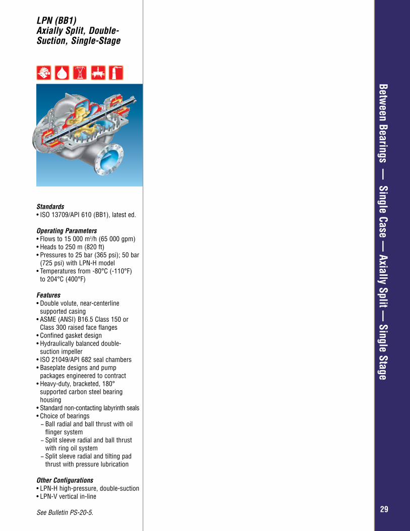
Single StageLPN (BB1)Axially Split, Double-Suction, Single-Stage
Standards• ISO 13709/API 610 (BB1), latest ed.
Operating Parameters• Flows to 15 000 m3/h (65 000 gpm)• Heads to 250 m (820 ft)• Pressures to 25 bar (365 psi); 50 bar
(725 psi) with LPN-H model• Temperatures from -80°C (-110°F)
to 204°C (400°F)
Features• Double volute, near-centerline
supported casing• ASME (ANSI) B16.5 Class 150 or
Class 300 raised face flanges • Confined gasket design• Hydraulically balanced double-
suction impeller• ISO 21049/API 682 seal chambers• Baseplate designs and pump
packages engineered to contract• Heavy-duty, bracketed, 180°
supported carbon steel bearing housing
• Standard non-contacting labyrinth seals• Choice of bearings
− Ball radial and ball thrust with oil flinger system − Split sleeve radial and ball thrust with ring oil system − Split sleeve radial and tilting pad thrust with pressure lubrication
Other Configurations• LPN-H high-pressure, double-suction• LPN-V vertical in-line
See Bulletin PS-20-5.
Overhung – General Industry
3030
Between Bearings —
Single Case — Axially Split —
Multistage
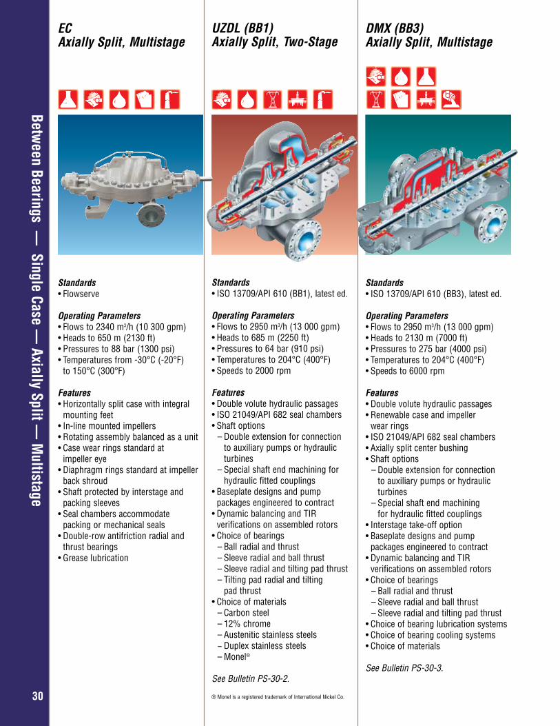
UZDL (BB1) Axially Split, Two-Stage
Standards• ISO 13709/API 610 (BB1), latest ed.
Operating Parameters• Flows to 2950 m3/h (13 000 gpm) • Heads to 685 m (2250 ft) • Pressures to 64 bar (910 psi) • Temperatures to 204°C (400°F)• Speeds to 2000 rpm
Features• Double volute hydraulic passages • ISO 21049/API 682 seal chambers • Shaft options
– Double extension for connection to auxiliary pumps or hydraulic turbines– Special shaft end machining for
hydraulic fitted couplings• Baseplate designs and pump
packages engineered to contract• Dynamic balancing and TIR
verifications on assembled rotors • Choice of bearings
– Ball radial and thrust – Sleeve radial and ball thrust – Sleeve radial and tilting pad thrust – Tilting pad radial and tilting
pad thrust • Choice of materials
– Carbon steel – 12% chrome – Austenitic stainless steels − Duplex stainless steels
– Monel®
See Bulletin PS-30-2.
® Monel is a registered trademark of International Nickel Co.
ECAxially Split, Multistage
Standards• Flowserve
Operating Parameters • Flows to 2340 m3/h (10 300 gpm)• Heads to 650 m (2130 ft)• Pressures to 88 bar (1300 psi)• Temperatures from -30°C (-20°F)
to 150°C (300°F)
Features• Horizontally split case with integral
mounting feet• In-line mounted impellers• Rotating assembly balanced as a unit• Case wear rings standard at
impeller eye• Diaphragm rings standard at impeller
back shroud• Shaft protected by interstage and
packing sleeves• Seal chambers accommodate
packing or mechanical seals• Double-row antifriction radial and
thrust bearings• Grease lubrication
DMX (BB3) Axially Split, Multistage
Standards• ISO 13709/API 610 (BB3), latest ed.
Operating Parameters• Flows to 2950 m3/h (13 000 gpm) • Heads to 2130 m (7000 ft) • Pressures to 275 bar (4000 psi) • Temperatures to 204°C (400°F) • Speeds to 6000 rpm
Features• Double volute hydraulic passages • Renewable case and impeller
wear rings• ISO 21049/API 682 seal chambers• Axially split center bushing • Shaft options
– Double extension for connection to auxiliary pumps or hydraulic turbines
– Special shaft end machining for hydraulic fitted couplings
• Interstage take-off option• Baseplate designs and pump
packages engineered to contract• Dynamic balancing and TIR
verifications on assembled rotors • Choice of bearings
– Ball radial and thrust – Sleeve radial and ball thrust – Sleeve radial and tilting pad thrust
• Choice of bearing lubrication systems• Choice of bearing cooling systems • Choice of materials
See Bulletin PS-30-3.
Overhung – General Industry
3131
Between Bearings —
Single Case — Radially Split —
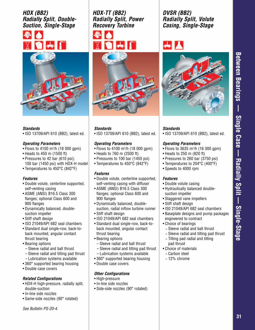
Single-StageHDX (BB2)Radially Split, Double-Suction, Single-Stage
HDX-TT (BB2) Radially Split, Power Recovery Turbine
DVSR (BB2)Radially Split, Volute Casing, Single-Stage
Standards• ISO 13709/API 610 (BB2), latest ed.
Operating Parameters• Flows to 4100 m3/h (18 000 gpm) • Heads to 450 m (1500 ft) • Pressures to 42 bar (610 psi);
100 bar (1450 psi) with HDX-H model• Temperatures to 450°C (842°F)
Features• Double volute, centerline supported,
self-venting casing • ASME (ANSI) B16.5 Class 300
flanges; optional Class 600 and 900 flanges
• Dynamically balanced, double- suction impeller• Stiff shaft design • ISO 21049/API 682 seal chambers • Standard dual single-row, back-to-
back mounted, angular contact thrust bearing
• Bearing options– Sleeve radial and ball thrust – Sleeve radial and tilting pad thrust– Lubrication systems available
• 360° supported bearing housing • Double case covers
Related Configurations• HDX-H high-pressure, radially split,
double-suction• In-line side nozzles • Same-side nozzles (90° rotated)
See Bulletin PS-20-4.
Standards• ISO 13709/API 610 (BB2), latest ed.
Operating Parameters• Flows to 4100 m3/h (18 000 gpm) • Heads to 760 m (2500 ft) • Pressures to 100 bar (1450 psi)• Temperatures to 450°C (842°F)
Features• Double volute, centerline supported,
self-venting casing with diffuser • ASME (ANSI) B16.5 Class 300
flanges; optional Class 600 and 900 flanges
• Dynamically balanced, double- suction, radial inflow turbine runner • Stiff shaft design • ISO 21049/API 682 seal chambers • Standard dual single-row, back-to-
back mounted, angular contact thrust bearing
• Bearing options– Sleeve radial and ball thrust – Sleeve radial and tilting pad thrust– Lubrication systems available
• 360° supported bearing housing • Double case covers
Other Configurations• High-pressure• In-line side nozzles • Side-side nozzles (90° rotated)
Standards• ISO 13709/API 610 (BB2), latest ed.
Operating Parameters• Flows to 3635 m3/h (16 000 gpm)• Heads to 250 m (820 ft)• Pressures to 260 bar (3750 psi)• Temperatures to 204°C (400°F)• Speeds to 4000 rpm
Features• Double volute casing• Hydraulically balanced double-
suction impeller• Staggered vane impellers• Stiff shaft design• IS0 21049/API 682 seal chambers• Baseplate designs and pump packages
engineered to contract• Choice of bearings
− Sleeve radial and ball thrust − Sleeve radial and tilting pad thrust − Tilting pad radial and tilting pad thrust
• Choice of materials − Carbon steel − 12% chrome
Overhung – General Industry
3232
Between Bearings —
Single Case — Radially Split —
Multistage
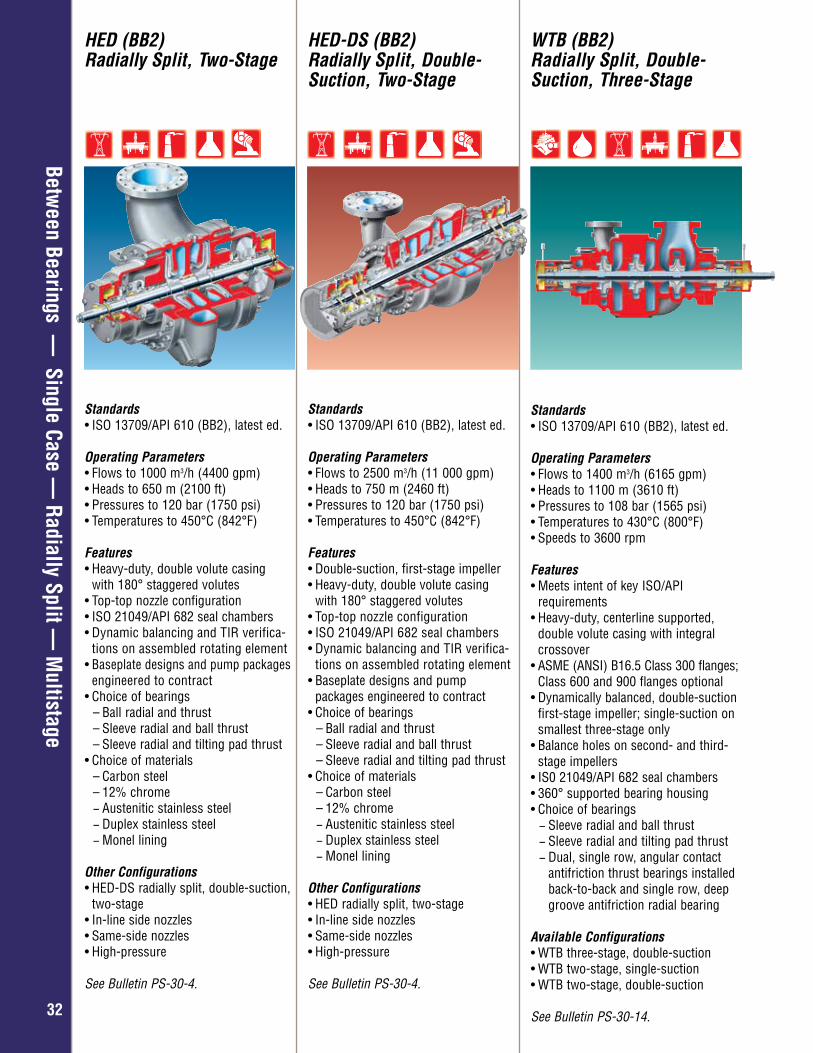
HED (BB2) Radially Split, Two-Stage
HED-DS (BB2) Radially Split, Double-Suction, Two-Stage
WTB (BB2)Radially Split, Double-Suction, Three-Stage
Standards • ISO 13709/API 610 (BB2), latest ed.
Operating Parameters• Flows to 1000 m3/h (4400 gpm) • Heads to 650 m (2100 ft) • Pressures to 120 bar (1750 psi) • Temperatures to 450°C (842°F)
Features• Heavy-duty, double volute casing
with 180° staggered volutes• Top-top nozzle configuration• ISO 21049/API 682 seal chambers • Dynamic balancing and TIR verifica-
tions on assembled rotating element• Baseplate designs and pump packages
engineered to contract• Choice of bearings
– Ball radial and thrust – Sleeve radial and ball thrust – Sleeve radial and tilting pad thrust
• Choice of materials – Carbon steel – 12% chrome − Austenitic stainless steel − Duplex stainless steel − Monel lining
Other Configurations• HED-DS radially split, double-suction,
two-stage• In-line side nozzles• Same-side nozzles• High-pressure
See Bulletin PS-30-4.
Standards• ISO 13709/API 610 (BB2), latest ed.
Operating Parameters• Flows to 2500 m3/h (11 000 gpm) • Heads to 750 m (2460 ft) • Pressures to 120 bar (1750 psi) • Temperatures to 450°C (842°F)
Features• Double-suction, first-stage impeller• Heavy-duty, double volute casing
with 180° staggered volutes• Top-top nozzle configuration• ISO 21049/API 682 seal chambers • Dynamic balancing and TIR verifica-
tions on assembled rotating element • Baseplate designs and pump
packages engineered to contract• Choice of bearings
– Ball radial and thrust – Sleeve radial and ball thrust – Sleeve radial and tilting pad thrust
• Choice of materials – Carbon steel – 12% chrome − Austenitic stainless steel − Duplex stainless steel − Monel lining
Other Configurations• HED radially split, two-stage• In-line side nozzles• Same-side nozzles• High-pressure
See Bulletin PS-30-4.
Standards• ISO 13709/API 610 (BB2), latest ed.
Operating Parameters• Flows to 1400 m3/h (6165 gpm)• Heads to 1100 m (3610 ft)• Pressures to 108 bar (1565 psi)• Temperatures to 430°C (800°F)• Speeds to 3600 rpm
Features• Meets intent of key ISO/API
requirements• Heavy-duty, centerline supported,
double volute casing with integral crossover
• ASME (ANSI) B16.5 Class 300 flanges; Class 600 and 900 flanges optional
• Dynamically balanced, double-suction first-stage impeller; single-suction on smallest three-stage only
• Balance holes on second- and third- stage impellers
• IS0 21049/API 682 seal chambers• 360° supported bearing housing• Choice of bearings
− Sleeve radial and ball thrust − Sleeve radial and tilting pad thrust − Dual, single row, angular contact antifriction thrust bearings installed back-to-back and single row, deep groove antifriction radial bearing
Available Configurations• WTB three-stage, double-suction• WTB two-stage, single-suction• WTB two-stage, double-suction
See Bulletin PS-30-14.
Overhung – General Industry
3333
Between Bearings —
Single Case — Radially Split —
Multistage
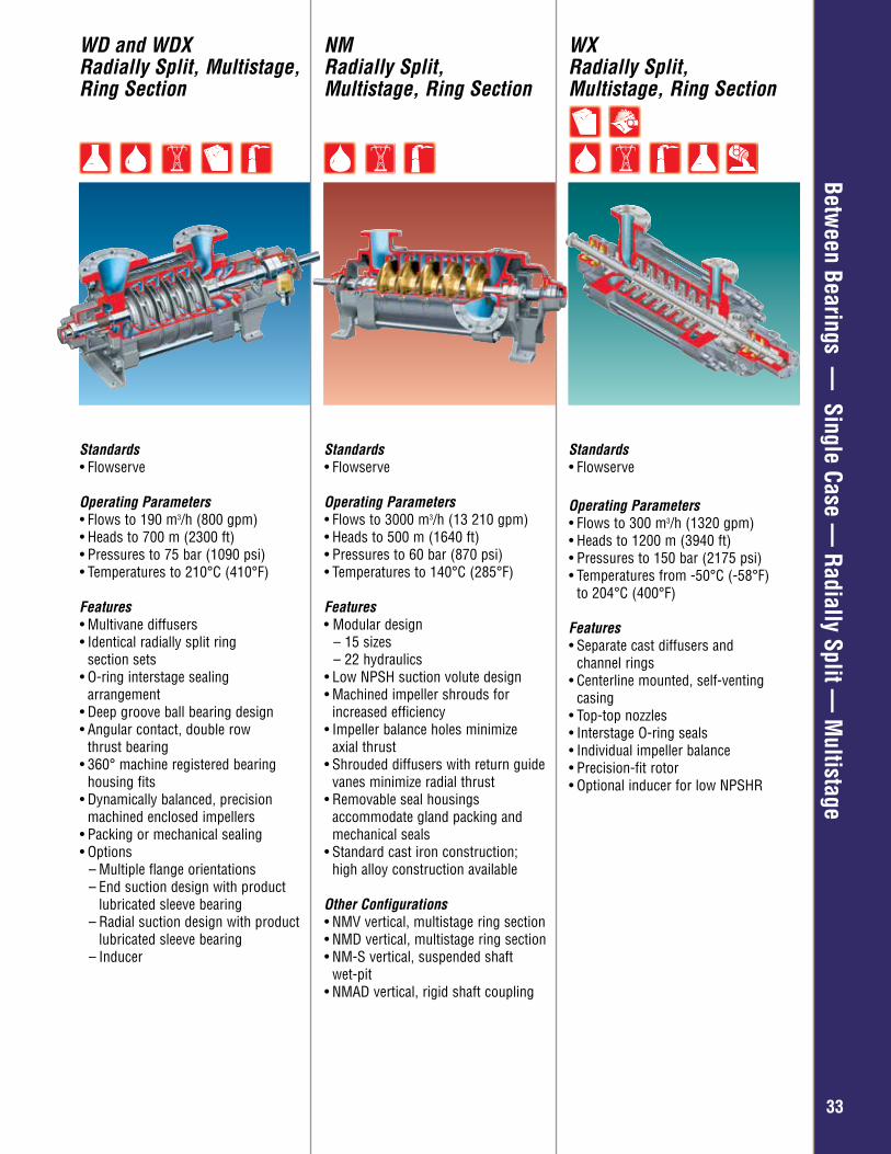
WX Radially Split, Multistage, Ring Section
Standards• Flowserve
Operating Parameters• Flows to 300 m3/h (1320 gpm)• Heads to 1200 m (3940 ft)• Pressures to 150 bar (2175 psi)• Temperatures from -50°C (-58°F)
to 204°C (400°F)
Features• Separate cast diffusers and
channel rings• Centerline mounted, self-venting
casing• Top-top nozzles • Interstage O-ring seals• Individual impeller balance• Precision-fit rotor• Optional inducer for low NPSHR
WD and WDX Radially Split, Multistage, Ring Section
NM Radially Split, Multistage, Ring Section
Standards• Flowserve Operating Parameters• Flows to 190 m3/h (800 gpm) • Heads to 700 m (2300 ft) • Pressures to 75 bar (1090 psi) • Temperatures to 210°C (410°F)
Features• Multivane diffusers• Identical radially split ring section sets• O-ring interstage sealing
arrangement • Deep groove ball bearing design• Angular contact, double row thrust bearing • 360° machine registered bearing
housing fits • Dynamically balanced, precision
machined enclosed impellers• Packing or mechanical sealing• Options
– Multiple flange orientations– End suction design with product
lubricated sleeve bearing– Radial suction design with product
lubricated sleeve bearing – Inducer
Standards• Flowserve
Operating Parameters• Flows to 3000 m3/h (13 210 gpm)• Heads to 500 m (1640 ft)• Pressures to 60 bar (870 psi) • Temperatures to 140°C (285°F)
Features• Modular design
– 15 sizes– 22 hydraulics
• Low NPSH suction volute design • Machined impeller shrouds for
increased efficiency• Impeller balance holes minimize
axial thrust• Shrouded diffusers with return guide
vanes minimize radial thrust• Removable seal housings
accommodate gland packing and mechanical seals
• Standard cast iron construction; high alloy construction available
Other Configurations• NMV vertical, multistage ring section • NMD vertical, multistage ring section • NM-S vertical, suspended shaft
wet-pit• NMAD vertical, rigid shaft coupling
Overhung – General Industry
3434
Between Bearings —
Single Case — Radially Split —
Multistage
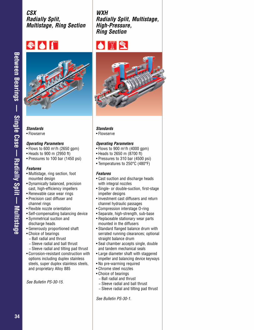
CSX Radially Split, Multistage, Ring Section
Standards• Flowserve
Operating Parameters• Flows to 600 m3/h (2650 gpm) • Heads to 900 m (2950 ft) • Pressures to 100 bar (1450 psi)
Features• Multistage, ring section, foot
mounted design• Dynamically balanced, precision
cast, high-efficiency impellers• Renewable case wear rings• Precision cast diffuser and
channel rings• Flexible nozzle orientation• Self-compensating balancing device• Symmetrical suction and
discharge heads• Generously proportioned shaft• Choice of bearings
− Ball radial and thrust − Sleeve radial and ball thrust − Sleeve radial and tilting pad thrust
• Corrosion-resistant construction with options including duplex stainless steels, super duplex stainless steels, and proprietary Alloy 885
See Bulletin PS-30-15.
WXH Radially Split, Multistage, High-Pressure, Ring Section
Standards• Flowserve
Operating Parameters• Flows to 900 m3/h (4000 gpm) • Heads to 2650 m (8700 ft) • Pressures to 310 bar (4500 psi) • Temperatures to 250°C (480°F)
Features• Cast suction and discharge heads with integral nozzles• Single- or double-suction, first-stage
impeller designs• Investment cast diffusers and return
channel hydraulic passages• Compression interstage O-ring • Separate, high-strength, sub-base • Replaceable stationary wear parts
mounted in the diffusers • Standard flanged balance drum with
serrated running clearances; optional straight balance drum
• Seal chamber accepts single, double and tandem mechanical seals
• Large diameter shaft with staggered impeller and balancing device keyways
• No pre-warming required• Chrome steel nozzles • Choice of bearings
− Ball radial and thrust − Sleeve radial and ball thrust − Sleeve radial and tilting pad thrust
See Bulletin PS-30-1.
Overhung – General Industry
3535
Between Bearings —
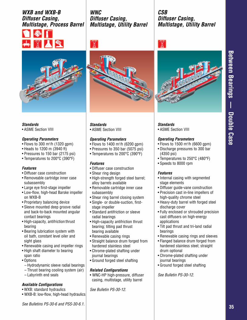
Double CaseWXB and WXB-B Diffuser Casing, Multistage, Process Barrel
Standards• ASME Section VIII
Operating Parameters• Flows to 300 m3/h (1320 gpm)• Heads to 1200 m (3940 ft) • Pressures to 150 bar (2175 psi) • Temperatures to 200°C (390°F)
Features• Diffuser case construction• Removeable cartridge inner case
subassembly• Large eye first-stage impeller • Low-flow, high-head Barske impeller
on WXB-B• Proprietary balancing device• Sleeve mounted deep groove radial
and back-to-back mounted angular contact bearings
• High-capacity, antifriction thrust bearing
• Bearing lubrication system with oil bath, constant level oiler and sight glass
• Renewable casing and impeller rings • High shaft diameter to bearing
span ratio• Options
– Hydrodynamic sleeve radial bearings– Thrust bearing cooling system (air)– Labyrinth end seals
Available Configurations• WXB: standard hydraulics• WXB-B: low-flow, high-head hydraulics
See Bulletins PS-30-6 and PSS-30-6.1.
WNCDiffuser Casing, Multistage, Utility Barrel
Standards• ASME Section VIII
Operating Parameters• Flows to 1400 m3/h (6200 gpm) • Pressures to 350 bar (5075 psi) • Temperatures to 200°C (390°F) Features• Diffuser case construction• Shear ring design• High-strength forged steel barrel;
alloy barrels available• Removable cartridge inner case
subassembly• Shear ring barrel closing system• Single- or double-suction, first-
stage impeller • Standard antifriction or sleeve
radial bearings• High-capacity antifriction thrust
bearing; tilting pad thrust bearing available
• Renewable casing rings • Straight balance drum forged from
hardened stainless steel • Chrome-plated shafting under
journal bearings • Ground forged steel shafting
Related Configurations• WNC-HP high-pressure, diffuser
casing, multistage, utility barrel
See Bulletin PS-30-12.
CSB Diffuser Casing, Multistage, Utility Barrel
Standards• ASME Section VIII
Operating Parameters• Flows to 1500 m3/h (6600 gpm) • Discharge pressures to 300 bar
(4350 psi) • Temperatures to 250°C (480°F) • Speeds to 8000 rpm
Features• Internal casing with segmented
stage elements• Diffuser guide-vane construction• Precision cast in-line impellers of
high-quality chrome steel • Heavy-duty barrel with forged steel discharge cover • Fully enclosed or shrouded precision
cast diffusers on high-energy applications
• Tilt pad thrust and tri-land radial bearings
• Renewable casing rings and sleeves • Flanged balance drum forged from
hardened stainless steel; straight drum optional
• Chrome-plated shafting under journal bearings
• Ground forged steel shafting
See Bulletin PS-30-12.
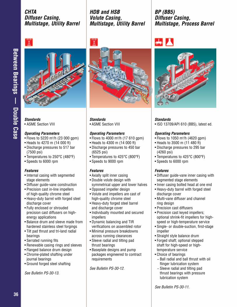
Overhung – General Industry
3636
Between Bearings —
Double Case
HDB and HSB Volute Casing, Multistage, Utility Barrel
BP (BB5) Diffuser Casing, Multistage, Process Barrel
Standards• ASME Section VIII
Operating Parameters• Flows to 4000 m3/h (17 610 gpm)• Heads to 4300 m (14 000 ft) • Discharge pressures to 450 bar
(6525 psi) • Temperatures to 425°C (800°F) • Speeds to 9000 rpm
Features• Axially split inner casing• Double volute design with
symmetrical upper and lower halves• Opposed impeller design • Volute and impellers are cast of
high-quality chrome steel• Heavy-duty forged steel barrel
and discharge cover• Individually mounted and secured
impellers • Dynamic balancing and TIR
verifications on assembled rotor • Minimal pressure breakdowns
across running clearances • Sleeve radial and tilting pad
thrust bearings • Baseplate designs and pump
packages engineered to contract requirements
See Bulletin PS-30-12.
Standards• ISO 13709/API 610 (BB5), latest ed.
Operating Parameters• Flows to 1050 m3/h (4620 gpm)• Heads to 3500 m (11 480 ft)• Discharge pressures to 295 bar
(4260 psi)• Temperatures to 425°C (800°F)• Speeds to 6000 rpm
Features• Diffuser guide-vane inner casing with
segmented stage elements• Inner casing bolted head at one end• Heavy-duty barrel with forged steel
discharge cover• Multi-vane diffuser and channel
ring design• Precision cast diffusers• Precision cast keyed impellers;
optional shrink-fit impellers for high- speed or high-temperature service
• Single- or double-suction, first-stage impeller
• Straight style balance drum• Forged shaft; optional stepped
shaft for high-speed or high- temperature service
• Choice of bearings − Ball radial and ball thrust with oil flinger lubrication system − Sleeve radial and tilting pad thrust bearings with pressure lubrication system
See Bulletin PS-30-11.
CHTA Diffuser Casing, Multistage, Utility Barrel
Standards• ASME Section VIII
Operating Parameters• Flows to 5220 m3/h (23 000 gpm) • Heads to 4270 m (14 000 ft)• Discharge pressures to 517 bar
(7500 psi) • Temperatures to 250°C (480°F) • Speeds to 6000 rpm
Features• Internal casing with segmented
stage elements• Diffuser guide-vane construction• Precision cast in-line impellers
of high-quality chrome steel • Heavy-duty barrel with forged steel
discharge cover • Fully enclosed or shrouded
precision cast diffusers on high- energy applications
• Balance drum and sleeve made from hardened stainless steel forgings
• Tilt pad thrust and tri-land radial bearings
• Serrated running fits • Renewable casing rings and sleeves • Flanged balance drum design • Chrome-plated shafting under
journal bearings • Ground forged steel shafting
See Bulletin PS-30-13.
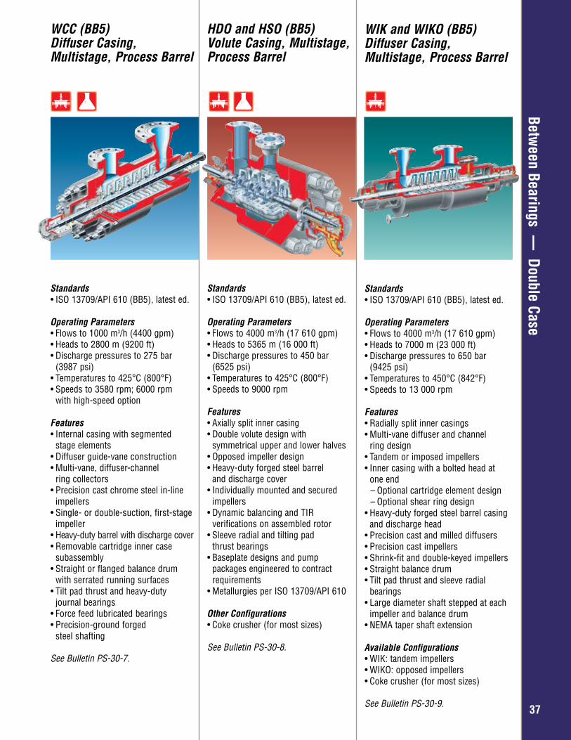
Overhung – General Industry
3737
Between Bearings —
Double CaseHDO and HSO (BB5)Volute Casing, Multistage, Process Barrel
Standards• ISO 13709/API 610 (BB5), latest ed.
Operating Parameters• Flows to 4000 m3/h (17 610 gpm)• Heads to 5365 m (16 000 ft) • Discharge pressures to 450 bar
(6525 psi) • Temperatures to 425°C (800°F) • Speeds to 9000 rpm
Features• Axially split inner casing• Double volute design with
symmetrical upper and lower halves• Opposed impeller design • Heavy-duty forged steel barrel
and discharge cover • Individually mounted and secured
impellers • Dynamic balancing and TIR
verifications on assembled rotor • Sleeve radial and tilting pad
thrust bearings • Baseplate designs and pump
packages engineered to contract requirements
• Metallurgies per ISO 13709/API 610
Other Configurations • Coke crusher (for most sizes)
See Bulletin PS-30-8.
WCC (BB5) Diffuser Casing, Multistage, Process Barrel
Standards• ISO 13709/API 610 (BB5), latest ed.
Operating Parameters• Flows to 1000 m3/h (4400 gpm)• Heads to 2800 m (9200 ft)• Discharge pressures to 275 bar
(3987 psi)• Temperatures to 425°C (800°F)• Speeds to 3580 rpm; 6000 rpm
with high-speed option
Features• Internal casing with segmented stage elements• Diffuser guide-vane construction• Multi-vane, diffuser-channel
ring collectors• Precision cast chrome steel in-line
impellers• Single- or double-suction, first-stage
impeller • Heavy-duty barrel with discharge cover • Removable cartridge inner case
subassembly • Straight or flanged balance drum
with serrated running surfaces • Tilt pad thrust and heavy-duty
journal bearings • Force feed lubricated bearings• Precision-ground forged
steel shafting
See Bulletin PS-30-7.
WIK and WIKO (BB5) Diffuser Casing, Multistage, Process Barrel
Standards• ISO 13709/API 610 (BB5), latest ed. Operating Parameters• Flows to 4000 m3/h (17 610 gpm)• Heads to 7000 m (23 000 ft) • Discharge pressures to 650 bar
(9425 psi) • Temperatures to 450°C (842°F) • Speeds to 13 000 rpm
Features• Radially split inner casings • Multi-vane diffuser and channel
ring design• Tandem or imposed impellers• Inner casing with a bolted head at
one end – Optional cartridge element design – Optional shear ring design
• Heavy-duty forged steel barrel casing and discharge head
• Precision cast and milled diffusers• Precision cast impellers• Shrink-fit and double-keyed impellers• Straight balance drum • Tilt pad thrust and sleeve radial
bearings• Large diameter shaft stepped at each
impeller and balance drum • NEMA taper shaft extension
Available Configurations • WIK: tandem impellers• WIKO: opposed impellers• Coke crusher (for most sizes)
See Bulletin PS-30-9.
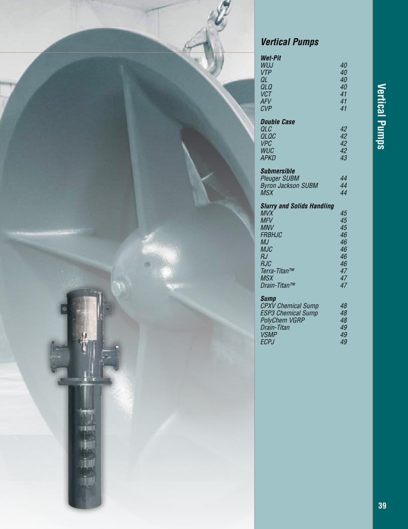
Vertical Pumps
39
Vertical Pumps Wet-Pit WUJ 40VTP 40QL 40QLQ 40VCT 41AFV 41CVP 41
Double CaseQLC 42QLQC 42VPC 42WUC 42APKD 43
Submersible Pleuger SUBM 44Byron Jackson SUBM 44MSX 44
Slurry and Solids HandlingMVX 45MFV 45MNV 45FRBHJC 46MJ 46MJC 46RJ 46RJC 46Terra-Titan™ 47MSX 47Drain-Titan™ 47
SumpCPXV Chemical Sump 48ESP3 Chemical Sump 48PolyChem VGRP 48Drain-Titan 49VSMP 49ECPJ 49
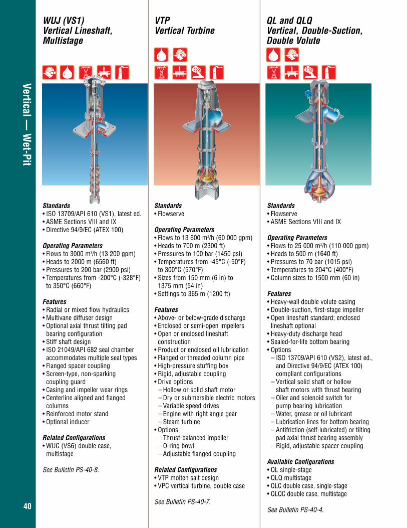
4040
Vertical — W
et-Pit
QL and QLQ Vertical, Double-Suction, Double Volute
Standards• Flowserve• ASME Sections VIII and IX
Operating Parameters• Flows to 25 000 m3/h (110 000 gpm) • Heads to 500 m (1640 ft) • Pressures to 70 bar (1015 psi) • Temperatures to 204°C (400°F) • Column sizes to 1500 mm (60 in)
Features • Heavy-wall double volute casing • Double-suction, first-stage impeller • Open lineshaft standard; enclosed
lineshaft optional• Heavy-duty discharge head• Sealed-for-life bottom bearing • Options
– ISO 13709/API 610 (VS2), latest ed., and Directive 94/9/EC (ATEX 100) compliant configurations
– Vertical solid shaft or hollow shaft motors with thrust bearing – Oiler and solenoid switch for pump bearing lubrication – Water, grease or oil lubricant – Lubrication lines for bottom bearing– Antifriction (self-lubricated) or tilting
pad axial thrust bearing assembly – Rigid, adjustable spacer coupling
Available Configurations • QL single-stage• QLQ multistage• QLC double case, single-stage • QLQC double case, multistage
See Bulletin PS-40-4.
VTP Vertical Turbine
WUJ (VS1) Vertical Lineshaft, Multistage
Standards• Flowserve
Operating Parameters• Flows to 13 600 m3/h (60 000 gpm) • Heads to 700 m (2300 ft) • Pressures to 100 bar (1450 psi) • Temperatures from -45°C (-50°F) to 300°C (570°F) • Sizes from 150 mm (6 in) to
1375 mm (54 in) • Settings to 365 m (1200 ft)
Features• Above- or below-grade discharge• Enclosed or semi-open impellers• Open or enclosed lineshaft
construction• Product or enclosed oil lubrication• Flanged or threaded column pipe• High-pressure stuffing box• Rigid, adjustable coupling • Drive options
– Hollow or solid shaft motor– Dry or submersible electric motors– Variable speed drives– Engine with right angle gear– Steam turbine
• Options– Thrust-balanced impeller – O-ring bowl– Adjustable flanged coupling
Related Configurations • VTP molten salt design• VPC vertical turbine, double case
See Bulletin PS-40-7.
Standards• ISO 13709/API 610 (VS1), latest ed. • ASME Sections VIII and IX • Directive 94/9/EC (ATEX 100)
Operating Parameters• Flows to 3000 m3/h (13 200 gpm) • Heads to 2000 m (6560 ft) • Pressures to 200 bar (2900 psi) • Temperatures from -200°C (-328°F)
to 350°C (660°F)
Features• Radial or mixed flow hydraulics • Multivane diffuser design• Optional axial thrust tilting pad bearing configuration • Stiff shaft design• ISO 21049/API 682 seal chamber
accommodates multiple seal types• Flanged spacer coupling • Screen-type, non-sparking
coupling guard • Casing and impeller wear rings• Centerline aligned and flanged
columns • Reinforced motor stand • Optional inducer
Related Configurations • WUC (VS6) double case, multistage See Bulletin PS-40-8.
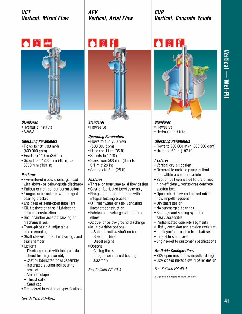
4141
Vertical — W
et-PitAFV Vertical, Axial Flow
CVP Vertical, Concrete Volute
Standards• Flowserve
Operating Parameters• Flows to 181 700 m3/h
(800 000 gpm) • Heads to 11 m (35 ft) • Speeds to 1770 rpm • Sizes from 200 mm (8 in) to
3.1 m (123 in) • Settings to 8 m (25 ft)
Features• Three- or four-vane axial flow design • Cast or fabricated bowl assembly • Flanged outer column pipe with
integral bearing bracket • Oil, freshwater or self-lubricating
lineshaft construction • Fabricated discharge with mitered
elbow • Above- or below-ground discharge • Multiple drive options
− Solid or hollow shaft motor − Steam turbine − Diesel engine
• Options − Casing liners − Integral axial thrust bearing assembly
See Bulletin PS-40-3.
Standards• Hydraulic Institute• AWWA
Operating Parameters• Flows to 181 700 m3/h
(800 000 gpm) • Heads to 110 m (350 ft)• Sizes from 1200 mm (48 in) to 3380 mm (133 in)
Features• Five-mitered elbow discharge head
with above- or below-grade discharge• Pullout or non-pullout construction• Flanged outer column with integral
bearing bracket• Enclosed or semi-open impellers• Oil, freshwater or self-lubricating column construction• Seal chamber accepts packing or mechanical seal• Three-piece rigid, adjustable
motor coupling • Shaft sleeves under the bearings and
seal chamber• Options
– Discharge head with integral axial thrust bearing assembly
– Cast or fabricated bowl assembly– Integrated suction bell bearing
bracket– Multiple stages– Thrust collar– Sand cap
• Engineered to customer specifications
See Bulletin PS-40-6.
VCT Vertical, Mixed Flow
Standards• Flowserve• Hydraulic Institute
Operating Parameters• Flows to 200 000 m3/h (800 000 gpm) • Heads to 60 m (197 ft)
Features• Vertical dry-pit design• Removable metallic pump pullout
unit within a concrete volute• Suction bell connected to preformed
high-efficiency, vortex-free concrete suction box
• Open mixed flow and closed mixed flow impeller options
• Dry shaft design• No submerged bearings• Bearings and sealing systems easily accessible • Prefabricated concrete segments • Highly corrosion and erosion resistant• Liquidyne® or mechanical shaft seal • Inflatable static seal• Engineered to customer specifications
Available Configurations• BSV open mixed flow impeller design• BCV closed mixed flow impeller design
See Bulletin PS-40-1.
® Liquidyne is a registered trademark of IHC.
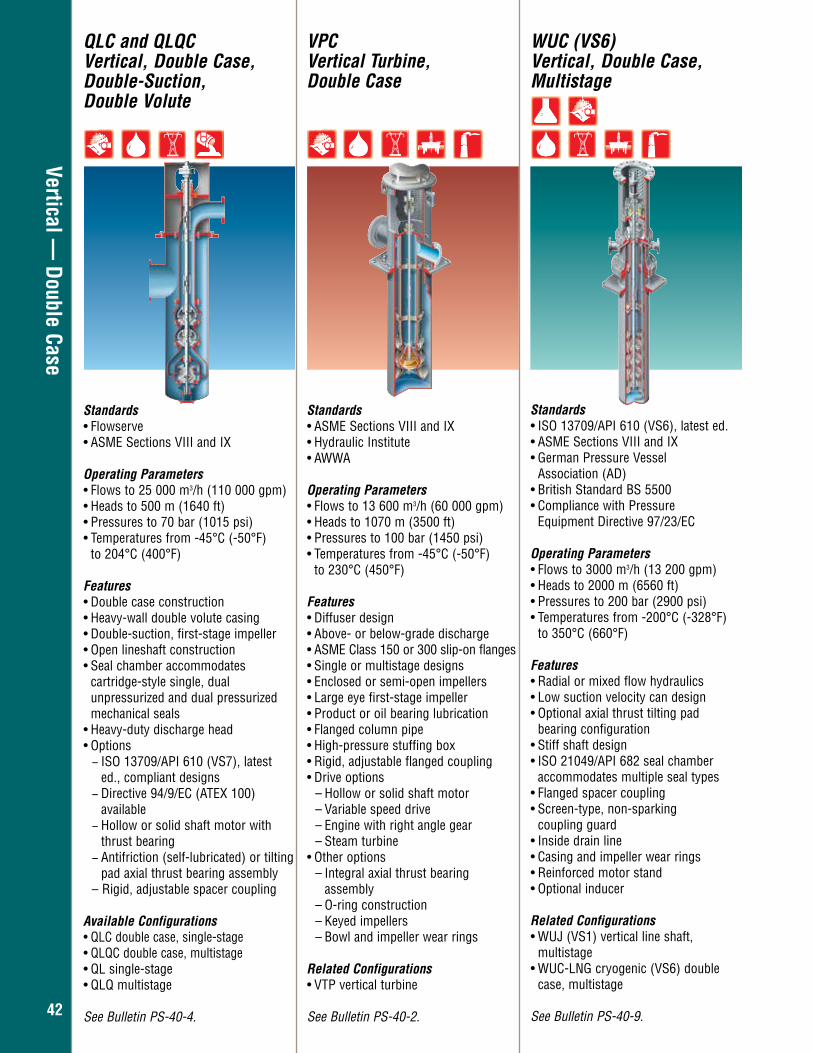
4242
Vertical — Double Case
QLC and QLQC Vertical, Double Case, Double-Suction, Double Volute
Standards• Flowserve• ASME Sections VIII and IX
Operating Parameters• Flows to 25 000 m3/h (110 000 gpm) • Heads to 500 m (1640 ft) • Pressures to 70 bar (1015 psi) • Temperatures from -45°C (-50°F)
to 204°C (400°F)
Features • Double case construction• Heavy-wall double volute casing • Double-suction, first-stage impeller • Open lineshaft construction• Seal chamber accommodates
cartridge-style single, dual unpressurized and dual pressurized mechanical seals
• Heavy-duty discharge head• Options
− ISO 13709/API 610 (VS7), latest ed., compliant designs − Directive 94/9/EC (ATEX 100) available − Hollow or solid shaft motor with thrust bearing − Antifriction (self-lubricated) or tilting pad axial thrust bearing assembly
– Rigid, adjustable spacer coupling
Available Configurations • QLC double case, single-stage • QLQC double case, multistage • QL single-stage• QLQ multistage
See Bulletin PS-40-4.
WUC (VS6) Vertical, Double Case, Multistage
Standards• ISO 13709/API 610 (VS6), latest ed.• ASME Sections VIII and IX • German Pressure Vessel
Association (AD) • British Standard BS 5500 • Compliance with Pressure
Equipment Directive 97/23/EC
Operating Parameters• Flows to 3000 m3/h (13 200 gpm) • Heads to 2000 m (6560 ft) • Pressures to 200 bar (2900 psi) • Temperatures from -200°C (-328°F) to 350°C (660°F)
Features• Radial or mixed flow hydraulics • Low suction velocity can design • Optional axial thrust tilting pad
bearing configuration • Stiff shaft design • ISO 21049/API 682 seal chamber
accommodates multiple seal types• Flanged spacer coupling • Screen-type, non-sparking
coupling guard • Inside drain line • Casing and impeller wear rings • Reinforced motor stand • Optional inducer
Related Configurations • WUJ (VS1) vertical line shaft,
multistage• WUC-LNG cryogenic (VS6) double
case, multistage
See Bulletin PS-40-9.
VPC Vertical Turbine, Double Case
Standards• ASME Sections VIII and IX• Hydraulic Institute• AWWA
Operating Parameters• Flows to 13 600 m3/h (60 000 gpm) • Heads to 1070 m (3500 ft) • Pressures to 100 bar (1450 psi) • Temperatures from -45°C (-50°F)
to 230°C (450°F)
Features• Diffuser design• Above- or below-grade discharge• ASME Class 150 or 300 slip-on flanges• Single or multistage designs• Enclosed or semi-open impellers• Large eye first-stage impeller• Product or oil bearing lubrication• Flanged column pipe• High-pressure stuffing box• Rigid, adjustable flanged coupling • Drive options
– Hollow or solid shaft motor– Variable speed drive– Engine with right angle gear– Steam turbine
• Other options– Integral axial thrust bearing
assembly – O-ring construction– Keyed impellers– Bowl and impeller wear rings
Related Configurations • VTP vertical turbine
See Bulletin PS-40-2.
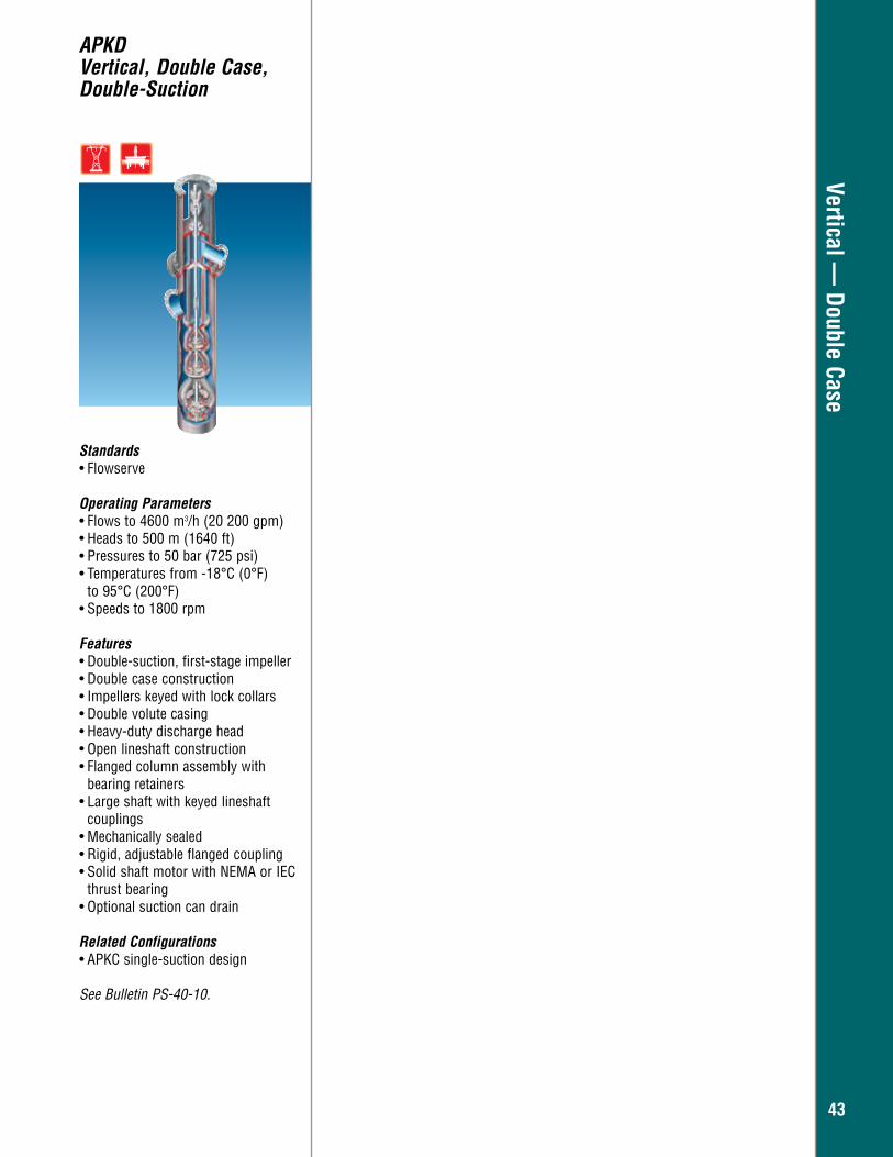
4343
Vertical — Double Case
APKDVertical, Double Case, Double-Suction
Standards• Flowserve
Operating Parameters• Flows to 4600 m3/h (20 200 gpm)• Heads to 500 m (1640 ft)• Pressures to 50 bar (725 psi) • Temperatures from -18°C (0°F)
to 95°C (200°F) • Speeds to 1800 rpm
Features• Double-suction, first-stage impeller• Double case construction• Impellers keyed with lock collars• Double volute casing• Heavy-duty discharge head• Open lineshaft construction• Flanged column assembly with
bearing retainers• Large shaft with keyed lineshaft
couplings• Mechanically sealed• Rigid, adjustable flanged coupling• Solid shaft motor with NEMA or IEC
thrust bearing• Optional suction can drain
Related Configurations • APKC single-suction design
See Bulletin PS-40-10.
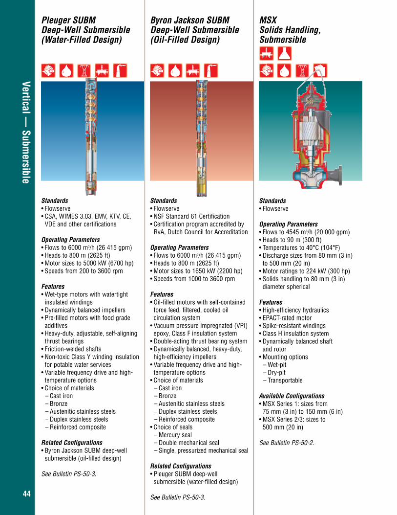
4444
Vertical — Subm
ersible
Pleuger SUBM Deep-Well Submersible (Water-Filled Design)
Byron Jackson SUBMDeep-Well Submersible(Oil-Filled Design)
Standards• Flowserve• CSA, WIMES 3.03, EMV, KTV, CE, VDE and other certifications
Operating Parameters• Flows to 6000 m3/h (26 415 gpm) • Heads to 800 m (2625 ft) • Motor sizes to 5000 kW (6700 hp)• Speeds from 200 to 3600 rpm
Features• Wet-type motors with watertight
insulated windings • Dynamically balanced impellers • Pre-filled motors with food grade additives • Heavy-duty, adjustable, self-aligning
thrust bearings • Friction-welded shafts • Non-toxic Class Y winding insulation
for potable water services • Variable frequency drive and high- temperature options • Choice of materials
– Cast iron – Bronze – Austenitic stainless steels − Duplex stainless steels
– Reinforced composite
Related Configurations • Byron Jackson SUBM deep-well submersible (oil-filled design)
See Bulletin PS-50-3.
Standards• Flowserve• NSF Standard 61 Certification • Certification program accredited by
RvA, Dutch Council for Accreditation
Operating Parameters• Flows to 6000 m3/h (26 415 gpm) • Heads to 800 m (2625 ft) • Motor sizes to 1650 kW (2200 hp) • Speeds from 1000 to 3600 rpm
Features• Oil-filled motors with self-contained
force feed, filtered, cooled oil circulation system • Vacuum pressure impregnated (VPI)
epoxy, Class F insulation system • Double-acting thrust bearing system • Dynamically balanced, heavy-duty, high-efficiency impellers • Variable frequency drive and high- temperature options • Choice of materials
– Cast iron – Bronze – Austenitic stainless steels − Duplex stainless steels
– Reinforced composite • Choice of seals
– Mercury seal – Double mechanical seal – Single, pressurized mechanical seal
Related Configurations • Pleuger SUBM deep-well submersible (water-filled design)
See Bulletin PS-50-3.
Standards• Flowserve
Operating Parameters• Flows to 4545 m3/h (20 000 gpm) • Heads to 90 m (300 ft) • Temperatures to 40°C (104°F)• Discharge sizes from 80 mm (3 in)
to 500 mm (20 in) • Motor ratings to 224 kW (300 hp) • Solids handling to 80 mm (3 in)
diameter spherical
Features • High-efficiency hydraulics • EPACT-rated motor • Spike-resistant windings • Class H insulation system • Dynamically balanced shaft and rotor • Mounting options
– Wet-pit – Dry-pit – Transportable
Available Configurations • MSX Series 1: sizes from 75 mm (3 in) to 150 mm (6 in)• MSX Series 2/3: sizes to 500 mm (20 in)
See Bulletin PS-50-2.
MSXSolids Handling, Submersible
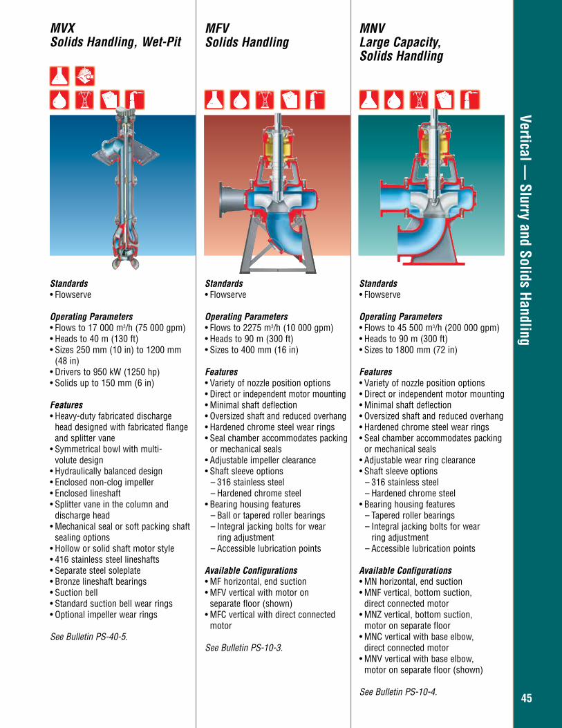
4545
Vertical — Slurry and Solids Handling
MVXSolids Handling, Wet-Pit
MFVSolids Handling
MNVLarge Capacity,Solids Handling
Standards• Flowserve
Operating Parameters• Flows to 2275 m3/h (10 000 gpm) • Heads to 90 m (300 ft) • Sizes to 400 mm (16 in)
Features• Variety of nozzle position options • Direct or independent motor mounting• Minimal shaft deflection• Oversized shaft and reduced overhang • Hardened chrome steel wear rings • Seal chamber accommodates packing
or mechanical seals• Adjustable impeller clearance• Shaft sleeve options
– 316 stainless steel – Hardened chrome steel
• Bearing housing features – Ball or tapered roller bearings – Integral jacking bolts for wear
ring adjustment – Accessible lubrication points
Available Configurations • MF horizontal, end suction• MFV vertical with motor on separate floor (shown)• MFC vertical with direct connected
motor
See Bulletin PS-10-3.
Standards• Flowserve
Operating Parameters• Flows to 45 500 m3/h (200 000 gpm) • Heads to 90 m (300 ft) • Sizes to 1800 mm (72 in)
Features• Variety of nozzle position options• Direct or independent motor mounting• Minimal shaft deflection• Oversized shaft and reduced overhang • Hardened chrome steel wear rings • Seal chamber accommodates packing
or mechanical seals • Adjustable wear ring clearance • Shaft sleeve options
– 316 stainless steel – Hardened chrome steel
• Bearing housing features – Tapered roller bearings – Integral jacking bolts for wear ring adjustment – Accessible lubrication points
Available Configurations • MN horizontal, end suction• MNF vertical, bottom suction,
direct connected motor • MNZ vertical, bottom suction,
motor on separate floor • MNC vertical with base elbow,
direct connected motor • MNV vertical with base elbow,
motor on separate floor (shown)
See Bulletin PS-10-4.
Standards• Flowserve
Operating Parameters• Flows to 17 000 m3/h (75 000 gpm) • Heads to 40 m (130 ft) • Sizes 250 mm (10 in) to 1200 mm
(48 in) • Drivers to 950 kW (1250 hp) • Solids up to 150 mm (6 in)
Features• Heavy-duty fabricated discharge
head designed with fabricated flange and splitter vane
• Symmetrical bowl with multi- volute design
• Hydraulically balanced design • Enclosed non-clog impeller• Enclosed lineshaft • Splitter vane in the column and discharge head • Mechanical seal or soft packing shaft
sealing options • Hollow or solid shaft motor style • 416 stainless steel lineshafts • Separate steel soleplate • Bronze lineshaft bearings • Suction bell • Standard suction bell wear rings • Optional impeller wear rings
See Bulletin PS-40-5.
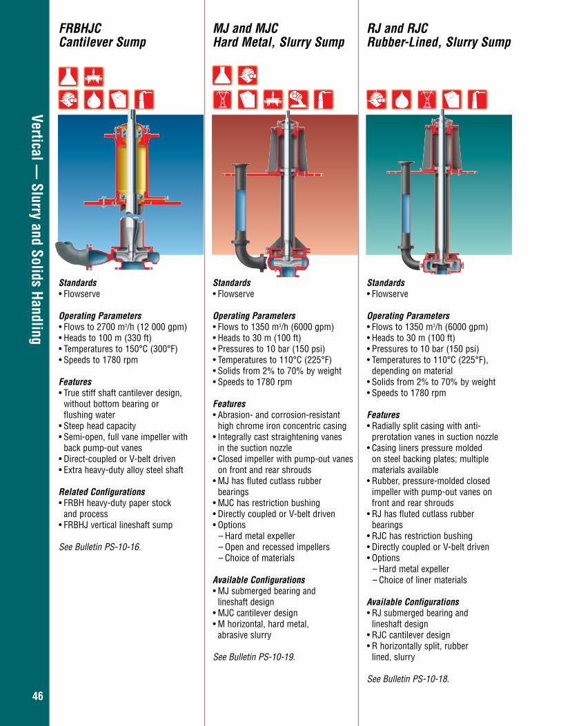
4646
Vertical — Slurry and Solids Handling
FRBHJC Cantilever Sump
MJ and MJCHard Metal, Slurry Sump
RJ and RJCRubber-Lined, Slurry Sump
Standards• Flowserve
Operating Parameters • Flows to 2700 m3/h (12 000 gpm) • Heads to 100 m (330 ft) • Temperatures to 150°C (300°F) • Speeds to 1780 rpm Features• True stiff shaft cantilever design,
without bottom bearing or flushing water
• Steep head capacity • Semi-open, full vane impeller with
back pump-out vanes • Direct-coupled or V-belt driven• Extra heavy-duty alloy steel shaft
Related Configurations • FRBH heavy-duty paper stock
and process• FRBHJ vertical lineshaft sump
See Bulletin PS-10-16.
Standards• Flowserve
Operating Parameters• Flows to 1350 m3/h (6000 gpm) • Heads to 30 m (100 ft) • Pressures to 10 bar (150 psi) • Temperatures to 110°C (225°F) • Solids from 2% to 70% by weight • Speeds to 1780 rpm Features • Abrasion- and corrosion-resistant
high chrome iron concentric casing • Integrally cast straightening vanes
in the suction nozzle • Closed impeller with pump-out vanes
on front and rear shrouds • MJ has fluted cutlass rubber bearings • MJC has restriction bushing• Directly coupled or V-belt driven • Options
– Hard metal expeller – Open and recessed impellers – Choice of materials
Available Configurations • MJ submerged bearing and
lineshaft design• MJC cantilever design• M horizontal, hard metal,
abrasive slurry
See Bulletin PS-10-19.
Standards• Flowserve
Operating Parameters• Flows to 1350 m3/h (6000 gpm) • Heads to 30 m (100 ft) • Pressures to 10 bar (150 psi) • Temperatures to 110°C (225°F),
depending on material • Solids from 2% to 70% by weight • Speeds to 1780 rpm
Features • Radially split casing with anti-
prerotation vanes in suction nozzle• Casing liners pressure molded
on steel backing plates; multiple materials available
• Rubber, pressure-molded closed impeller with pump-out vanes on front and rear shrouds
• RJ has fluted cutlass rubber bearings • RJC has restriction bushing• Directly coupled or V-belt driven • Options
– Hard metal expeller – Choice of liner materials
Available Configurations • RJ submerged bearing and
lineshaft design• RJC cantilever design • R horizontally split, rubber
lined, slurry
See Bulletin PS-10-18.
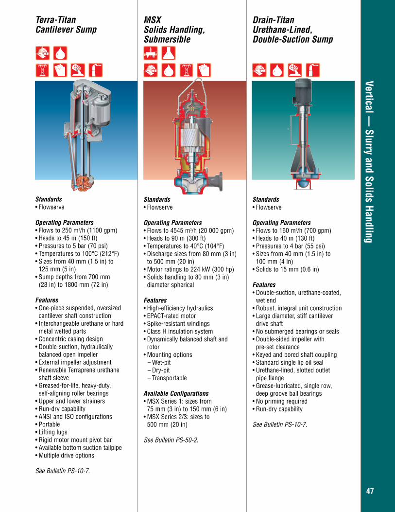
4747
Vertical — Slurry and Solids Handling
Terra-Titan Cantilever Sump
Standards• Flowserve
Operating Parameters • Flows to 250 m3/h (1100 gpm) • Heads to 45 m (150 ft) • Pressures to 5 bar (70 psi) • Temperatures to 100°C (212°F) • Sizes from 40 mm (1.5 in) to
125 mm (5 in) • Sump depths from 700 mm
(28 in) to 1800 mm (72 in)
Features• One-piece suspended, oversized
cantilever shaft construction• Interchangeable urethane or hard
metal wetted parts • Concentric casing design• Double-suction, hydraulically
balanced open impeller • External impeller adjustment • Renewable Terraprene urethane
shaft sleeve • Greased-for-life, heavy-duty,
self-aligning roller bearings• Upper and lower strainers • Run-dry capability• ANSI and ISO configurations • Portable • Lifting lugs • Rigid motor mount pivot bar• Available bottom suction tailpipe• Multiple drive options
See Bulletin PS-10-7.
Drain-Titan Urethane-Lined, Double-Suction Sump
Standards• Flowserve
Operating Parameters • Flows to 160 m3/h (700 gpm) • Heads to 40 m (130 ft) • Pressures to 4 bar (55 psi)• Sizes from 40 mm (1.5 in) to
100 mm (4 in)• Solids to 15 mm (0.6 in)
Features• Double-suction, urethane-coated, wet end • Robust, integral unit construction• Large diameter, stiff cantilever
drive shaft • No submerged bearings or seals• Double-sided impeller with
pre-set clearance• Keyed and bored shaft coupling• Standard single lip oil seal• Urethane-lined, slotted outlet
pipe flange• Grease-lubricated, single row,
deep groove ball bearings• No priming required• Run-dry capability
See Bulletin PS-10-7.
Standards• Flowserve
Operating Parameters• Flows to 4545 m3/h (20 000 gpm) • Heads to 90 m (300 ft) • Temperatures to 40°C (104°F)• Discharge sizes from 80 mm (3 in)
to 500 mm (20 in) • Motor ratings to 224 kW (300 hp) • Solids handling to 80 mm (3 in)
diameter spherical
Features • High-efficiency hydraulics • EPACT-rated motor • Spike-resistant windings • Class H insulation system • Dynamically balanced shaft and
rotor • Mounting options
– Wet-pit – Dry-pit – Transportable
Available Configurations • MSX Series 1: sizes from 75 mm (3 in) to 150 mm (6 in)• MSX Series 2/3: sizes to 500 mm (20 in)
See Bulletin PS-50-2.
MSXSolids Handling, Submersible
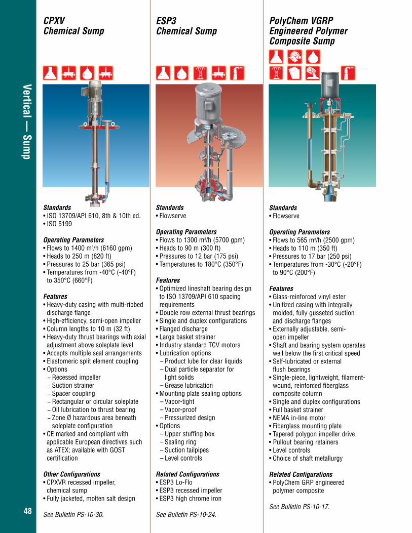
4848
Vertical — Sum
p
ESP3Chemical Sump
Standards• Flowserve
Operating Parameters• Flows to 1300 m3/h (5700 gpm) • Heads to 90 m (300 ft) • Pressures to 12 bar (175 psi) • Temperatures to 180°C (350°F)
Features • Optimized lineshaft bearing design to ISO 13709/API 610 spacing
requirements• Double row external thrust bearings • Single and duplex configurations • Flanged discharge • Large basket strainer • Industry standard TCV motors • Lubrication options
– Product lube for clear liquids – Dual particle separator for
light solids – Grease lubrication
• Mounting plate sealing options – Vapor-tight – Vapor-proof – Pressurized design
• Options – Upper stuffing box – Sealing ring – Suction tailpipes – Level controls
Related Configurations • ESP3 Lo-Flo• ESP3 recessed impeller• ESP3 high chrome iron
See Bulletin PS-10-24.
PolyChem VGRP Engineered Polymer Composite Sump
Standards• Flowserve
Operating Parameters • Flows to 565 m3/h (2500 gpm) • Heads to 110 m (350 ft) • Pressures to 17 bar (250 psi) • Temperatures from -30°C (-20°F)
to 90°C (200°F) Features• Glass-reinforced vinyl ester • Unitized casing with integrally
molded, fully gusseted suction and discharge flanges
• Externally adjustable, semi- open impeller
• Shaft and bearing system operates well below the first critical speed
• Self-lubricated or external flush bearings• Single-piece, lightweight, filament-
wound, reinforced fiberglass composite column
• Single and duplex configurations • Full basket strainer • NEMA in-line motor • Fiberglass mounting plate • Tapered polygon impeller drive • Pullout bearing retainers • Level controls • Choice of shaft metallurgy
Related Configurations • PolyChem GRP engineered
polymer composite
See Bulletin PS-10-17.
CPXVChemical Sump
Standards• ISO 13709/API 610, 8th & 10th ed.• ISO 5199
Operating Parameters• Flows to 1400 m3/h (6160 gpm)• Heads to 250 m (820 ft)• Pressures to 25 bar (365 psi)• Temperatures from -40°C (-40°F)
to 350°C (660°F)
Features• Heavy-duty casing with multi-ribbed
discharge flange• High-efficiency, semi-open impeller • Column lengths to 10 m (32 ft) • Heavy-duty thrust bearings with axial
adjustment above soleplate level• Accepts multiple seal arrangements• Elastomeric split element coupling• Options
− Recessed impeller − Suction strainer − Spacer coupling − Rectangular or circular soleplate − Oil lubrication to thrust bearing − Zone Ø hazardous area beneath soleplate configuration
• CE marked and compliant with applicable European directives such as ATEX; available with GOST certification
Other Configurations• CPXVR recessed impeller,
chemical sump• Fully jacketed, molten salt design
See Bulletin PS-10-30.
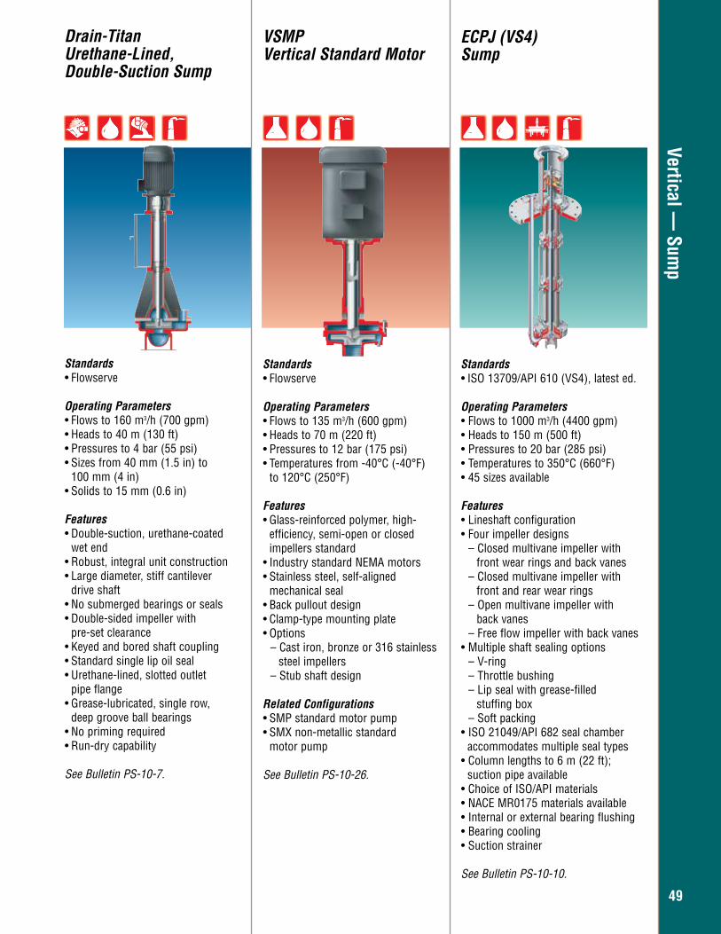
4949
Vertical — Sum
pDrain-TitanUrethane-Lined, Double-Suction Sump
Standards• Flowserve
Operating Parameters • Flows to 160 m3/h (700 gpm) • Heads to 40 m (130 ft) • Pressures to 4 bar (55 psi)• Sizes from 40 mm (1.5 in) to
100 mm (4 in)• Solids to 15 mm (0.6 in)
Features• Double-suction, urethane-coated wet end • Robust, integral unit construction• Large diameter, stiff cantilever
drive shaft • No submerged bearings or seals• Double-sided impeller with
pre-set clearance• Keyed and bored shaft coupling• Standard single lip oil seal• Urethane-lined, slotted outlet
pipe flange• Grease-lubricated, single row,
deep groove ball bearings• No priming required• Run-dry capability
See Bulletin PS-10-7.
VSMPVertical Standard Motor
ECPJ (VS4)Sump
Standards• Flowserve
Operating Parameters• Flows to 135 m3/h (600 gpm)• Heads to 70 m (220 ft)• Pressures to 12 bar (175 psi)• Temperatures from -40°C (-40°F) to 120°C (250°F)
Features• Glass-reinforced polymer, high- efficiency, semi-open or closed
impellers standard• Industry standard NEMA motors • Stainless steel, self-aligned mechanical seal• Back pullout design• Clamp-type mounting plate• Options
– Cast iron, bronze or 316 stainless steel impellers
– Stub shaft design
Related Configurations • SMP standard motor pump • SMX non-metallic standard motor pump
See Bulletin PS-10-26.
Standards• ISO 13709/API 610 (VS4), latest ed.
Operating Parameters• Flows to 1000 m3/h (4400 gpm)• Heads to 150 m (500 ft)• Pressures to 20 bar (285 psi)• Temperatures to 350°C (660°F)• 45 sizes available
Features• Lineshaft configuration• Four impeller designs
– Closed multivane impeller with front wear rings and back vanes – Closed multivane impeller with front and rear wear rings – Open multivane impeller with back vanes – Free flow impeller with back vanes
• Multiple shaft sealing options– V-ring– Throttle bushing– Lip seal with grease-filled stuffing box– Soft packing
• ISO 21049/API 682 seal chamber accommodates multiple seal types
• Column lengths to 6 m (22 ft); suction pipe available
• Choice of ISO/API materials• NACE MR0175 materials available• Internal or external bearing flushing• Bearing cooling• Suction strainer
See Bulletin PS-10-10.
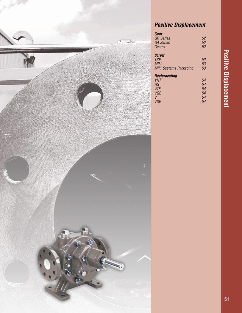
Positive Displacement
51
Positive DisplacementGearGR Series 52GA Series 52Gearex 52
ScrewTSP 53MP1 53MP1 Systems Packaging 53
ReciprocatingYHT 54HS 54VTE 54VQE 54V 54VSE 54
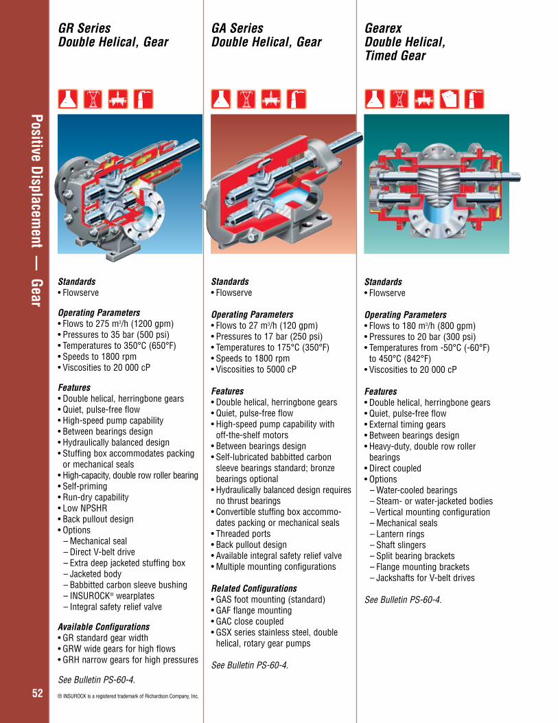
Overhung – General Industry
5252
Positive Displacement —
Gear
GR SeriesDouble Helical, Gear
GA SeriesDouble Helical, Gear
GearexDouble Helical,Timed Gear
Standards• Flowserve
Operating Parameters • Flows to 275 m3/h (1200 gpm) • Pressures to 35 bar (500 psi) • Temperatures to 350°C (650°F) • Speeds to 1800 rpm • Viscosities to 20 000 cP
Features• Double helical, herringbone gears • Quiet, pulse-free flow • High-speed pump capability • Between bearings design • Hydraulically balanced design • Stuffing box accommodates packing
or mechanical seals• High-capacity, double row roller bearing • Self-priming • Run-dry capability • Low NPSHR • Back pullout design • Options
– Mechanical seal – Direct V-belt drive – Extra deep jacketed stuffing box – Jacketed body – Babbitted carbon sleeve bushing – INSUROCK® wearplates – Integral safety relief valve
Available Configurations• GR standard gear width• GRW wide gears for high flows• GRH narrow gears for high pressures
See Bulletin PS-60-4.
® INSUROCK is a registered trademark of Richardson Company, Inc.
Standards• Flowserve
Operating Parameters • Flows to 27 m3/h (120 gpm) • Pressures to 17 bar (250 psi) • Temperatures to 175°C (350°F)• Speeds to 1800 rpm • Viscosities to 5000 cP Features • Double helical, herringbone gears • Quiet, pulse-free flow • High-speed pump capability with
off-the-shelf motors• Between bearings design • Self-lubricated babbitted carbon
sleeve bearings standard; bronze bearings optional
• Hydraulically balanced design requires no thrust bearings
• Convertible stuffing box accommo-dates packing or mechanical seals
• Threaded ports • Back pullout design • Available integral safety relief valve • Multiple mounting configurations
Related Configurations• GAS foot mounting (standard)• GAF flange mounting • GAC close coupled • GSX series stainless steel, double
helical, rotary gear pumps
See Bulletin PS-60-4.
Standards• Flowserve
Operating Parameters • Flows to 180 m3/h (800 gpm) • Pressures to 20 bar (300 psi) • Temperatures from -50°C (-60°F)
to 450°C (842°F) • Viscosities to 20 000 cP
Features• Double helical, herringbone gears • Quiet, pulse-free flow • External timing gears • Between bearings design • Heavy-duty, double row roller
bearings • Direct coupled • Options
– Water-cooled bearings – Steam- or water-jacketed bodies – Vertical mounting configuration – Mechanical seals – Lantern rings – Shaft slingers – Split bearing brackets – Flange mounting brackets – Jackshafts for V-belt drives
See Bulletin PS-60-4.
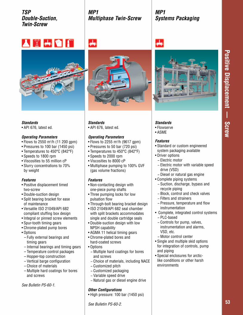
Overhung – General Industry
5353
Positive Displacement —
ScrewMP1Multiphase Twin-Screw
MP1Systems Packaging
TSPDouble-Suction, Twin-Screw
Standards• API 676, latest ed.
Operating Parameters • Flows to 2255 m3/h (9617 gpm) • Pressures to 50 bar (720 psi) • Temperatures to 450°C (842°F)• Speeds to 2000 rpm • Viscosities to 8000 cP• Multiphase pumping to 100% GVF
(gas volume fractions)
Features• Non-contacting design with
one-piece pump shafts• Three pumping locks for low
pulsation flow• Through-bolt bearing bracket design• ISO 21049/API 682 seal chamber
with split brackets accommodates single and double cartridge seals
• Double-suction design with low NPSH capability
• AGMA 11 helical timing gears• Chrome-plated bores and
hard-coated screws• Options
− Multiple hard coatings for bores and screws − Choice of materials, including NACE − Customized pitch − Customized packaging − Variable speed drive − Natural gas or diesel engine drive
Other Configurations• High pressure: 100 bar (1450 psi)
See Bulletin PS-60-2.
Standards• Flowserve• ASME Features• Standard or custom engineered
system packaging available• Driver options
− Electric motor − Electric motor with variable speed drive (VSD) − Diesel or natural gas engine
• Complete piping systems − Suction, discharge, bypass and recycle piping − Block, control and check valves − Filters and strainers − Pressure, temperature and flow instrumentation
• Complete, integrated control systems − PLC-based − Controls for pump, valves, instrumentation and alarms, VSD, etc. − Motor control center
• Single and multiple skid options for integration of controls, pump and piping
• Special enclosures for arctic- like conditions or other harsh environments
Standards• API 676, latest ed.
Operating Parameters• Flows to 2550 m3/h (11 200 gpm) • Pressures to 100 bar (1450 psi) • Temperatures to 450°C (842°F)• Speeds to 1800 rpm• Viscosities to 55 million cP• Slurry concentrations to 70% by weight
Features• Positive displacement timed
two-screw• Double-suction design• Split bearing bracket for ease
of maintenance• Versatile ISO 21049/API 682
compliant stuffing box design • Integral or pinned screw elements• Spur-tooth timing gears• Chrome-plated pump bores • Options
– Fully external bearings and timing gears
– Internal bearings and timing gears – Temperature control packages– Hopper-top construction– Vertical barge configuration – Choice of materials – Multiple hard coatings for bores
and screws
See Bulletin PS-60-1.
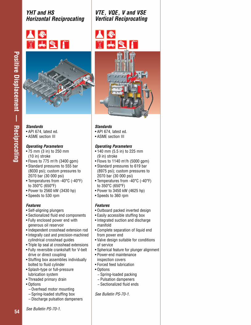
Overhung – General Industry
5454
Positive Displacement —
Reciprocating
YHT and HSHorizontal Reciprocating
VTE, VQE, V and VSE Vertical Reciprocating
Standards• API 674, latest ed.• ASME section III
Operating Parameters• 75 mm (3 in) to 250 mm
(10 in) stroke • Flows to 775 m3/h (3400 gpm)• Standard pressures to 555 bar
(8030 psi); custom pressures to 2070 bar (30 000 psi)
• Temperatures from -40°C (-40°F) to 350°C (650°F)
• Power to 2560 kW (3430 hp)• Speeds to 530 rpm
Features• Self-aligning plungers• Sectionalized fluid end components• Fully enclosed power end with generous oil reservoir• Independent crosshead extension rod• Integrally cast and precision-machined
cylindrical crosshead guides• Triple lip seal at crosshead extensions• Fully reversible crankshaft for V-belt
drive or direct coupling• Stuffing box assemblies individually
bolted to fluid cylinder• Splash-type or full-pressure lubrication system• Threaded primary drain• Options
– Overhead motor mounting– Spring-loaded stuffing box– Discharge pulsation dampeners
See Bulletin PS-70-1.
Standards• API 674, latest ed.• ASME section III
Operating Parameters• 140 mm (5.5 in) to 225 mm
(9 in) stroke • Flows to 1140 m3/h (5000 gpm)• Standard pressures to 619 bar
(8975 psi); custom pressures to 2070 bar (30 000 psi)
• Temperatures from -40°C (-40°F) to 350°C (650°F)
• Power to 3450 kW (4625 hp) • Speeds to 360 rpm
Features• Outboard packed inverted design • Easily accessible stuffing box • Integrated suction and discharge
manifold• Complete separation of liquid end
from power end• Valve design suitable for conditions
of service• Spherical feature for plunger alignment• Power-end maintenance
inspection covers • Forced feed lubrication• Options
− Spring-loaded packing − Pulsation dampeners − Sectionalized fluid ends
See Bulletin PS-70-1.

Overhung – General Industry
5555
Specialty Products
57
Specialty ProductsNuclear Pumps and SealsDFSS 58DVSS 58N-Seal 58WDF 58DVSR 59CN 59HDR 59CA 60CAM 60CAV 60EG 61MEV 61
Extreme Temperature WUC-LNG Cryogenic 62VKW Cryogenic 62TKW Cryogenic 62Byron Jackson 62 SUBM Geothermal
OthersHydraulic Decoking Systems 63IPS Products 63Pleuger WFSD 64 Azimuthing Thruster DWEER™ 64 ERT 64CVP 65Barge Pump 65Molten Salt VTP 65

Overhung – General Industry
5858
Specialty Products — Nuclear Pum
ps and Seals
DFSS and DVSSNuclear Radially Split, Single-Stage
WDF Nuclear Vertical, Single-Stage
Standards• ASME Section III, Class 1
Operating Parameters• Flows to 24 500 m3/h (108 000 gpm) • Heads to 250 m (820 ft) • Pressures to 170 bar (2500 psi) • Temperatures to 300°C (580°F) • Speeds to 1800 rpm • Power rating to 9400 kW (12 600 hp)
Services• Primary coolant• Reactor recirculation• Primary heat transport
Features• Fourth generation design • One-piece cast pump casing• Double volute design case for BWR
and PHWR• Diffuser with torus-type design casing for PWR• Upgraded rotating element
– One-piece welded shaft-impeller-journal assembly
– Fully machined and balanced as single rotating unit
• Hydrostatic-pressurized radial bearing– Operates submerged in radioactive
system water at loop temperature of approximately 300°C (580°F)
See Bulletin FPD-2.
Standards• ASME Section III, Class 2 and 3
Operating Parameters• Flows to 900 m3/h (4000 gpm) • Heads to 245 m (800 ft)
Services• Containment spray• Low-pressure safety injection• Residual heat removal
Features• Vertical, single-stage design• Bottom suction, horizontal discharge• Forged diffuser casing design• Optimized hydraulic performance• Unique spacer coupling design• Mechanical seal replacement without
motor or casing cover removal• Upgraded rotor design
– Radial bearing located between coupling and seal– Reduced shaft deflection– Improved pump and mechanical
seal life and reliability• Cartridge mechanical seal• Reduced assembly time
See Bulletin FPD-2.
Standards• ASME Section III, Class 1
Operating Parameters • Pressures to 150 bar (2175 psi)• Temperatures to 80°C (180°F)• Speeds to 1800 rpm
Services • Primary coolant• Reactor recirculation• Primary heat transport
Features• Controlled leakage seal design • Design life of five years or
50 000 hours • Reduced man-rem exposure • Unique one- or two-piece cartridge
construction • Two-, three- and four-stage
configurations • Assured redundancy with each stage
able to handle full system pressure • Interchangeable stage components • Hydrodynamic seal face technology • Three different seal face lift designs
available • Multiple seal face materials available • Provisions for monitoring pressure,
temperature and flow at each stage • Internal screens for trapping particles • Seal faces are supported by gaskets
to minimize pressure points and deflection
See Bulletin PS-80-2.
N-Seal Nuclear Mechanical Seals
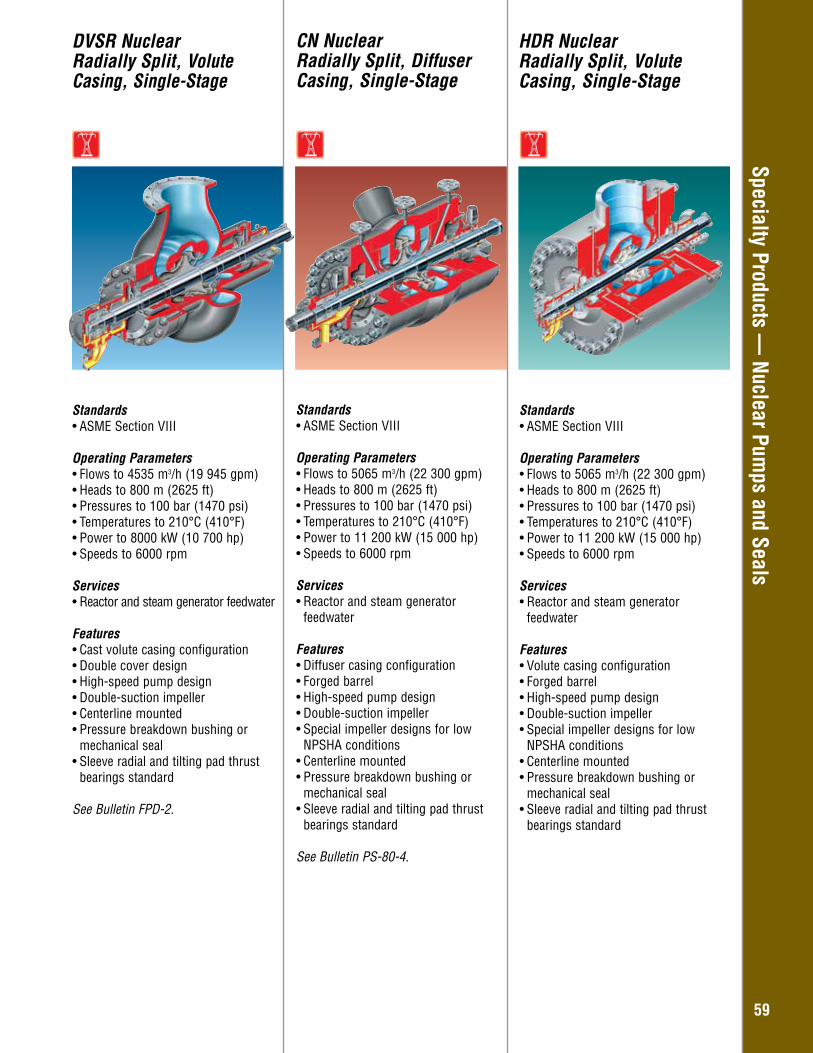
Overhung – General Industry
5959
Specialty Products — Nuclear Pum
ps and SealsDVSR Nuclear Radially Split, Volute Casing, Single-Stage
Standards• ASME Section VIII
Operating Parameters• Flows to 4535 m3/h (19 945 gpm)• Heads to 800 m (2625 ft)• Pressures to 100 bar (1470 psi)• Temperatures to 210°C (410°F)• Power to 8000 kW (10 700 hp)• Speeds to 6000 rpm
Services • Reactor and steam generator feedwater
Features• Cast volute casing configuration• Double cover design• High-speed pump design• Double-suction impeller• Centerline mounted• Pressure breakdown bushing or
mechanical seal• Sleeve radial and tilting pad thrust
bearings standard
See Bulletin FPD-2.
CN Nuclear Radially Split, Diffuser Casing, Single-Stage
Standards• ASME Section VIII
Operating Parameters• Flows to 5065 m3/h (22 300 gpm) • Heads to 800 m (2625 ft) • Pressures to 100 bar (1470 psi) • Temperatures to 210°C (410°F) • Power to 11 200 kW (15 000 hp) • Speeds to 6000 rpm
Services• Reactor and steam generator
feedwater
Features• Diffuser casing configuration• Forged barrel• High-speed pump design • Double-suction impeller• Special impeller designs for low
NPSHA conditions • Centerline mounted• Pressure breakdown bushing or
mechanical seal• Sleeve radial and tilting pad thrust
bearings standard
See Bulletin PS-80-4.
HDR Nuclear Radially Split, Volute Casing, Single-Stage
Standards• ASME Section VIII
Operating Parameters• Flows to 5065 m3/h (22 300 gpm) • Heads to 800 m (2625 ft) • Pressures to 100 bar (1470 psi) • Temperatures to 210°C (410°F) • Power to 11 200 kW (15 000 hp) • Speeds to 6000 rpm
Services• Reactor and steam generator
feedwater
Features• Volute casing configuration• Forged barrel• High-speed pump design • Double-suction impeller• Special impeller designs for low
NPSHA conditions • Centerline mounted• Pressure breakdown bushing or
mechanical seal• Sleeve radial and tilting pad thrust
bearings standard
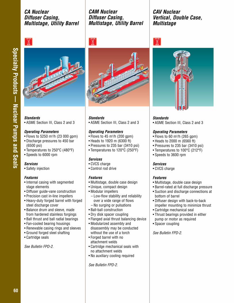
Overhung – General Industry
6060
Standards• ASME Section III, Class 2 and 3
Operating Parameters • Flows to 60 m3/h (265 gpm)• Heads to 2000 m (6560 ft)• Pressures to 235 bar (3410 psi)• Temperatures to 100°C (212°F)• Speeds to 3600 rpm
Services • CVCS charge
Features• Multistage, double case design• Barrel-rated at full discharge pressure• Suction and discharge connections at
bottom of barrel• Diffuser design with back-to-back
impeller mounting to minimize thrust• Cartridge mechanical seal• Thrust bearings provided in either
pump or motor as required• Spacer coupling
See Bulletin FPD-2.
CAV NuclearVertical, Double Case, Multistage
CA NuclearDiffuser Casing, Multistage, Utility Barrel
CAM Nuclear Diffuser Casing, Multistage, Utility Barrel
Standards• ASME Section III, Class 2 and 3
Operating Parameters• Flows to 45 m3/h (200 gpm) • Heads to 1920 m (6300 ft) • Pressures to 235 bar (3410 psi) • Temperatures to 120°C (250°F) Services• CVCS charge• Control rod drive
Features• Multistage, double case design • Unique, compact design • Modular impellers
– Low-flow stability and reliability over a wide range of flows
– No surging or pulsations• Ball-ball construction • Dry disk spacer coupling • Flanged axial thrust balancing device• Modularized assembly and
disassembly may be conducted without the use of a torch
• Forged barrel with no attachment welds
• Cartridge mechanical seals with no attachment welds
• No auxiliary cooling required
See Bulletin FPD-2.
Standards• ASME Section III, Class 2 and 3
Operating Parameters• Flows to 5250 m3/h (23 000 gpm) • Discharge pressures to 450 bar
(6500 psi) • Temperatures to 250°C (480°F) • Speeds to 6000 rpm
Services• Safety injection
Features• Internal casing with segmented
stage elements• Diffuser guide-vane construction• Precision cast in-line impellers• Heavy-duty forged barrel with forged
steel discharge cover • Balance drum and sleeve, made
from hardened stainless forgings• Ball thrust and ball radial bearings • Fan-cooled bearing housings• Renewable casing rings and sleeves • Ground forged steel shafting• Cartridge seals
See Bulletin FPD-2.
Specialty Products — Nuclear Pum
ps and Seals
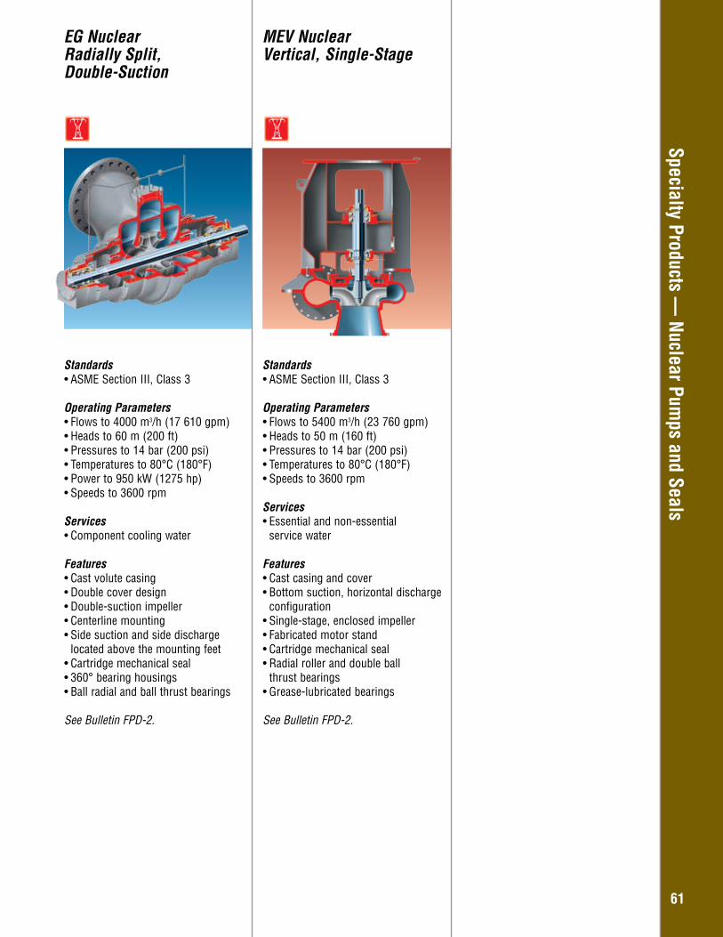
Overhung – General Industry
6161
Standards• ASME Section III, Class 3
Operating Parameters • Flows to 4000 m3/h (17 610 gpm)• Heads to 60 m (200 ft)• Pressures to 14 bar (200 psi)• Temperatures to 80°C (180°F)• Power to 950 kW (1275 hp)• Speeds to 3600 rpm
Services • Component cooling water
Features• Cast volute casing• Double cover design• Double-suction impeller• Centerline mounting• Side suction and side discharge
located above the mounting feet• Cartridge mechanical seal• 360° bearing housings• Ball radial and ball thrust bearings
See Bulletin FPD-2.
EG NuclearRadially Split, Double-Suction
Standards• ASME Section III, Class 3
Operating Parameters • Flows to 5400 m3/h (23 760 gpm)• Heads to 50 m (160 ft)• Pressures to 14 bar (200 psi)• Temperatures to 80°C (180°F)• Speeds to 3600 rpm
Services • Essential and non-essential
service water
Features• Cast casing and cover• Bottom suction, horizontal discharge
configuration• Single-stage, enclosed impeller• Fabricated motor stand• Cartridge mechanical seal• Radial roller and double ball
thrust bearings• Grease-lubricated bearings
See Bulletin FPD-2.
MEV Nuclear Vertical, Single-Stage
Specialty Products — Nuclear Pum
ps and Seals
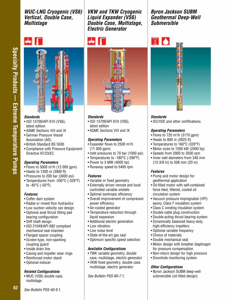
Overhung – General Industry
6262
Specialty Products — Extrem
e Temperature Pum
ps
WUC-LNG Cryogenic (VS6) Vertical, Double Case, Multistage
VKW and TKW Cryogenic Liquid Expander (VS6) Double Case, Multistage, Electric Generator
Byron Jackson SUBM Geothermal Deep-Well Submersible
Standards• ISO 13709/API 610 (VS6),
latest edition • ASME Sections VIII and IX• German Pressure Vessel
Association (AD)• British Standard BS 5500 • Compliance with Pressure Equipment
Directive 97/23/EC
Operating Parameters• Flows to 3000 m3/h (13 000 gpm) • Heads to 1200 m (3900 ft) • Pressures to 200 bar (3000 psi) • Temperatures from -200°C (-328°F) to -45°C (-50°F)
Features• Coffer dam system• Radial or mixed flow hydraulics • Low suction velocity can design • Optional axial thrust tilting pad bearing configuration • Stiff shaft design • ISO 21049/API 682 compliant
mechanical seal chamber • Flanged spacer coupling • Screen-type, non-sparking coupling guard • Inside drain line • Casing and impeller wear rings • Reinforced motor stand • Optional inducer
Related Configurations• WUC (VS6) double case,
multistage
See Bulletin PSS-40-9.1.
Standards• ISO 13709/API 610 (VS6),
latest edition • ASME Sections VIII and IX
Operating Parameters• Expander flows to 2500 m3/h (11 000 gpm) • Inlet pressures to 70 bar (1000 psi) • Temperatures to -180°C (-290°F)• Power to 3 MW (4000 hp)• Runaway speed to 5400 rpm
Features• Variable or fixed geometry • Externally driven remote and local
controlled variable wickets• Optimal isentropic efficiency• Overall improvement of compressor
power efficiency• Air-cooled generator• Temperature reduction through liquid expansion• Additional electric generation• Low vibration• Low noise level• State-of-the-art gas seal• Optimum specific speed selection
Available Configurations• TWK variable geometry, double
case, multistage, electric generator• VKW fixed geometry, double case,
multistage, electric generator
See Bulletin PSS-90-7.1.
Standards• IEC/VDE and other certifications
Operating Parameters• Flows to 720 m3/h (3170 gpm)• Heads to 800 m (2625 ft)• Temperatures to 160°C (320°F)• Motor sizes to 1500 kW (2000 hp)• Speeds from 2900 to 3500 rpm• Inner well diameters from 340 mm
(13-3/8 in) to 508 mm (20 in)
Features• Pump and motor design for
geothermal application• Oil-filled motor with self-contained
force feed, filtered, cooled oil circulation system
• Vacuum pressure impregnated (VPI) epoxy, Class F insulation system
• Class C winding insulation system • Double cable plug construction• Double-acting thrust bearing system • Dynamically balanced heavy-duty,
high-efficiency impellers• Optional variable frequency• Choice of materials • Double mechanical seal • Motor design with breather diaphragm
for pressure compensation• Non-return design for high pressure• Downhole monitoring system Other Configurations• Byron Jackson SUBM deep-well
submersible (oil-filled design)

Overhung – General Industry
6363
Specialty Products — Others
Hydraulic Decoking Systems
Intelligent Process Solutions (IPS)• Family of equipment monitoring
and control products that helps to proactively manage plant assets
− Collect key system parameters − Analyze and synthesize data into actionable information − Protect process equipment via automated responses − Transmit information to enable a timely manual response
• Increase uptime • Reduce operating costs
IPS Wireless• Cost-effective and scalable data
acquisition system • Open platform architecture • Omni-directional technology
IPS APEX • Advanced diagnostics• Intelligent control algorithms protect
against high-risk process conditions
IPS Tempo • Variable frequency drive • Intelligent system optimization
IPS Power Monitor • Monitors actual power usage• Programmable start-up delay and
low and high trip points
See Bulletin PS-90-11.
Flowserve Automated Hydraulic Decoking Systems • Increase delayed coking unit (DCU)
capacity and improve operator safety• Installed in more than 95% of the
world’s DCUs• Complete systems with virtually all
equipment needed to operate and control the hydraulic decoking process
• Extensive aftermarket support including specialists to evaluate system performance, improve reliability, and recommend operational and safety best practices
Complete Coke Cutting Systems • Jet pump train: ISO 13709/API 610
(BB5) jet pump, driver, lube oil skid and control system panel
• Coke cutting system: decoking control valve, AutoShift™ combination cutting tool, rotary joint, isolation and bleed valves, drill stem, tool guide and enclosure and high-pressure hose
• Cutting assembly lifting system: crosshead, free-fall arresters, winches and winch controls, pulley blocks, and latch mechanism to stow the crosshead
• Automation, controls and instrumentation
AutoShift Combination Cutting Tool• Removes the operator from the
cutting deck• Mode shifting is accomplished
automatically and remotely by water pressurization and depressurization
• Provides greater system automation and improved efficiency while improving operator safety, reducing cycle time and easing maintenance
• Mode shifting helps to free impeded tools from slumped beds
Advanced Cutting Control• Complete systems and enclosures
to monitor and control the operations• Continuous feedback signals
indicate equipment and drum status (i.e., position in drum, rotational speed, wore rope tension, etc.)
• Embedded intelligence to process data for monitoring and control; operator interface only required for sequence exception
• Video and acoustic equipment to monitor cutting deck operations and coke chute conditions
• Remote winch and rotary joint operation
• Remote sensing of cutting jet impingement on the coke drum
• Interlocking safety systems• IPS APEX™ data monitoring,
transmission and control systems Online Assurance Programs• Access to data aggregation tools via
the Technology Advantage™ Portal• Enable experts to monitor, diagnose
and communicate operating solutions to increase unit uptime
See Bulletin PS-90-6.
IPS Equipment Monitoring and Control Products
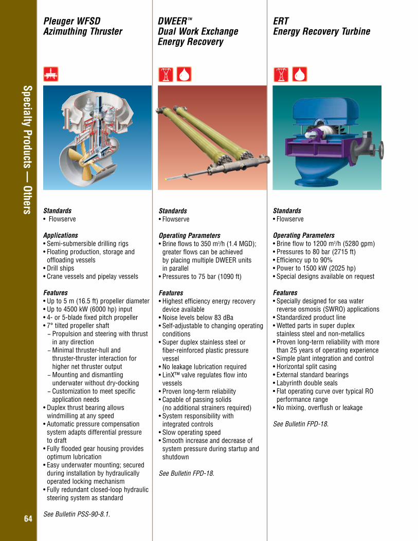
Overhung – General Industry
6464
Specialty Products — Others
DWEER TM
Dual Work Exchange Energy Recovery
ERTEnergy Recovery Turbine
Standards• Flowserve
Operating Parameters • Brine flows to 350 m3/h (1.4 MGD);
greater flows can be achieved by placing multiple DWEER units in parallel
• Pressures to 75 bar (1090 ft)
Features• Highest efficiency energy recovery
device available• Noise levels below 83 dBa• Self-adjustable to changing operating
conditions• Super duplex stainless steel or
fiber-reinforced plastic pressure vessel
• No leakage lubrication required• LinX™ valve regulates flow into
vessels• Proven long-term reliability• Capable of passing solids
(no additional strainers required)• System responsibility with
integrated controls• Slow operating speed• Smooth increase and decrease of
system pressure during startup and shutdown
See Bulletin FPD-18.
Standards• Flowserve
Operating Parameters • Brine flow to 1200 m3/h (5280 gpm)• Pressures to 80 bar (2715 ft)• Efficiency up to 90%• Power to 1500 kW (2025 hp)• Special designs available on request
Features• Specially designed for sea water
reverse osmosis (SWRO) applications• Standardized product line• Wetted parts in super duplex
stainless steel and non-metallics• Proven long-term reliability with more
than 25 years of operating experience• Simple plant integration and control• Horizontal split casing• External standard bearings• Labyrinth double seals• Flat operating curve over typical RO
performance range• No mixing, overflush or leakage
See Bulletin FPD-18.
Standards• Flowserve Applications• Semi-submersible drilling rigs• Floating production, storage and
offloading vessels• Drill ships• Crane vessels and pipelay vessels Features• Up to 5 m (16.5 ft) propeller diameter• Up to 4500 kW (6000 hp) input• 4- or 5-blade fixed pitch propeller• 7° tilted propeller shaft
− Propulsion and steering with thrust in any direction − Minimal thruster-hull and thruster-thruster interaction for higher net thruster output − Mounting and dismantling underwater without dry-docking − Customization to meet specific application needs
• Duplex thrust bearing allows windmilling at any speed
• Automatic pressure compensation system adapts differential pressure to draft
• Fully flooded gear housing provides optimum lubrication
• Easy underwater mounting; secured during installation by hydraulically operated locking mechanism
• Fully redundant closed-loop hydraulic steering system as standard
See Bulletin PSS-90-8.1.
Pleuger WFSD Azimuthing Thruster
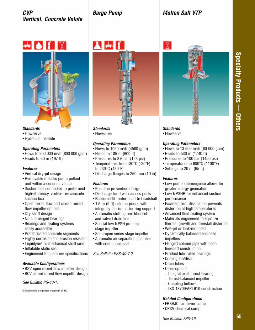
Overhung – General Industry
6565
Specialty Products — OthersStandards
• Flowserve
Operating Parameters• Flows to 1020 m3/h (4500 gpm) • Heads to 185 m (600 ft) • Pressures to 8.6 bar (125 psi)• Temperatures from -30°C (-20°F)
to 230°C (450°F) • Discharge flanges to 250 mm (10 in)
Features• Pollution prevention design• Discharge head with access ports• Rabbeted-fit motor shaft to headshaft• 1.5 m (5 ft) column pieces with
integrally fabricated bearing support• Automatic stuffing box bleed-off
and valved drain line • Special low NPSH priming
stage impeller• Semi-open series stage impeller• Automatic air separation chamber
with continuous seal
See Bulletin PSS-40-7.2.
Barge PumpCVPVertical, Concrete Volute
Standards• Flowserve• Hydraulic Institute
Operating Parameters• Flows to 200 000 m3/h (800 000 gpm) • Heads to 60 m (197 ft)
Features• Vertical dry-pit design• Removable metallic pump pullout
unit within a concrete volute• Suction bell connected to preformed
high-efficiency, vortex-free concrete suction box
• Open mixed flow and closed mixed flow impeller options
• Dry shaft design• No submerged bearings• Bearings and sealing systems easily accessible • Prefabricated concrete segments • Highly corrosion and erosion resistant• Liquidyne® or mechanical shaft seal • Inflatable static seal• Engineered to customer specifications
Available Configurations• BSV open mixed flow impeller design• BCV closed mixed flow impeller design
See Bulletin PS-40-1.
® Liquidyne is a registered trademark of IHC.
Molten Salt VTP
Standards • Flowserve Operating Parameters • Flows to 13 600 m3/h (60 000 gpm) • Heads to 530 m (1740 ft) • Pressures to 100 bar (1450 psi) • Temperatures to 600°C (1100°F) • Settings to 20 m (65 ft) Features • Low pump submergence allows for
greater energy generation • Low NPSHR for enhanced suction
performance • Excellent heat dissipation prevents
distortion at high temperatures • Advanced fluid sealing system• Materials engineered to equalize
thermal growth and forestall distortion • Wet-pit or tank-mounted • Dynamically balanced enclosed
impellers • Flanged column pipe with open
lineshaft construction • Product lubricated bearings• Cooling fan/disc• Drain tubes• Other options
− Integral axial thrust bearing − Thrust-balanced impeller − Coupling bellows − ISO 13709/API 610 construction
Related Configurations • FRBHJC cantilever sump• CPXV chemical sump See Bulletin FPD-16.

Additional Information
67
Additional InformationServices and Solutions 68Other Flowserve Products 70Reference Sources 71
68
The business and operational challenges within a process plant are numerous. Plant operators face the pressures of increased productivity and profits that are seemingly at odds with the every-day realities of decreased operating budgets, rising energy costs and increasing operational costs. But Flowserve Services and Solutions can help relieve the stresses and reduce the life cycle costs associated with the most important aspects of plant operation. Dedicated to delivering the highest quality support, Flowserve Services and Solutions integrates hydraulic, mechanical, and materials engineering knowledge with creative operating and business solutions to:
• Improve equipment reliability and performance• Reduce energy consumption• Manage inventories• Maintain flow management equipment
Services and Solutions for the Global Infrastructure Markets
Integrated Solutions That Support the Complete Life CycleTypically, 90% of the total life cycle cost (LCC) of a flow management system is accumulated after the equipment is purchased and installed. Flowserve offers a comprehensive suite of services and solutions designed to provide customers with unprecedented value and cost savings throughout the life span of the system.• Asset Management and Optimization• Engineering and Technical Services • Education and Training• Aftermarket Parts and Services
90%Operating Cost
69
flowserve.com
Asset Management and OptimizationFlowserve has developed the human resources, technology platforms and business alliances to help customers realize more payback from their plant assets.
• Business Assessments — Flowserve business consultants can benchmark operational performance, define the key metrics and implement the necessary steps to achieve specific goals.
• Asset Data Management — By employing sophisticated tools and technologies to collect, examine and understand data, Flowserve enables customers to reveal hidden opportunities for asset improvement.
• Asset Optimization Solutions — Flowserve offers a suite of performance-based contract services to address the key business and operational challenges of plant managers.
Engineering and Technical ServicesWith unrivaled engineering and technical resources in more than 55 countries, Flowserve delivers value-added solutions that improve operational performance and increase revenues for its customers.
• Engineering Support — Flowserve engineers can engage remotely or on-site to support grassroots project planning, system design or project management requirements.
• Technical Assessments — Flowserve can perform comprehensive system audits to identify operational issues that may be constraining output or elevating operating costs and propose solutions based upon life cycle cost (LCC) calculations.
• Equipment Performance Improvements — Flowserve routinely implements LCC-justified solutions to improve equipment performance, system throughput and unit profitability.
Education and TrainingFlowserve offers a wide range of innovative programs to help plant operators, reliability specialists, engineers and maintenance personnel deepen their understanding of process systems.
• Customer Site — Flowserve can design, develop, and deliver training programs tailored specifically around the people, equipment and processes at a customer’s facility.
• Learning Resource Center — At its state-of-the-art Learning Resource Centers, Flowserve provides hands-on training and instruction in the principles of equipment operation, maintenance and reliability.
• Online — Flowserve offers Web-based modules with online testing and data tracking to ensure comprehension of the most important principles.
Aftermarket Parts and ServicesInvestments in well-equipped Quick Response Centers, mobile service fleets, and advanced manufacturing technologies along with the unrivaled expertise of its engineers, technicians and craftsmen enable Flowserve to address virtually every service requirement for process equipment, on- or off-site, regardless of OEM.
• Repair and Maintenance — From machining to mechanical upgrades to on-site management, Flowserve repair and maintenance services focus on improving equipment performance while reducing downtime and costs.
• Replacement Parts and Components — Through quick response programs, rapid prototyping, and other innovative approaches, Flowserve can supply customers with the quality parts needed to keep operations running smoothly and profitably.
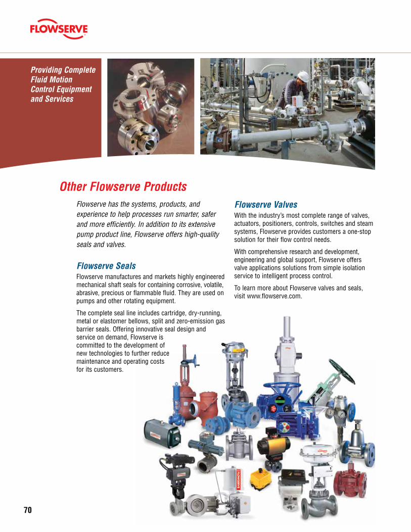
70
Flowserve ValvesWith the industry’s most complete range of valves, actuators, positioners, controls, switches and steam systems, Flowserve provides customers a one-stop solution for their flow control needs.
With comprehensive research and development, engineering and global support, Flowserve offers valve applications solutions from simple isolation service to intelligent process control.
To learn more about Flowserve valves and seals, visit www.flowserve.com.
Flowserve has the systems, products, and experience to help processes run smarter, safer and more efficiently. In addition to its extensive pump product line, Flowserve offers high-quality seals and valves.
Flowserve SealsFlowserve manufactures and markets highly engineered mechanical shaft seals for containing corrosive, volatile, abrasive, precious or flammable fluid. They are used on pumps and other rotating equipment.
The complete seal line includes cartridge, dry-running, metal or elastomer bellows, split and zero-emission gas barrier seals. Offering innovative seal design and service on demand, Flowserve is committed to the development of new technologies to further reduce maintenance and operating costs for its customers.
Other Flowserve Products
Providing Complete Fluid Motion Control Equipment and Services
71
flowserve.com
Cameron Hydraulic DataFirst published in 1926 and now in its 19th edition, the Cameron Hydraulic Data book is an indispensable aid to engineers involved with the specification, selection and application of pumping equipment. This comprehensive reference tool includes: • Hydraulic principles and formulae • Friction data• Properties of common liquids• Steam and electrical data• Weights, dimensions, and ratings of pipe
flanges and fittings• Metric conversions
To obtain a copy of the Cameron Hydraulic Data book, visit: www.cameronbook.com.
Pump Engineering ManualThis publication is devoted to explaining centrifugal pump principles. It covers the basics, from application analysis and affinity laws through hydraulics and mechanical phenomena to troubleshooting.
To obtain a copy of the Pump Engineering Manual, visit: www.cameronbook.com.
FlowSelex™ Interactive Pump Selection ApplicationFlowSelex is a Web-based interactive pump selection program that allows users to access an extensive database of Flowserve pump sizing information anytime, anywhere.
This versatile tool delivers a wide range of information, from pump descriptions and operating parameters to custom application package specifications with supporting technical documentation, including:
• Performance curves• Hydraulic data sheets• General arrangement drawings• Construction data sheets
FlowSelex can be accessed at www.Flowserve.com/FlowSelex.
Reference Sources
72
AAFV . . . . . . . . . . . . . . . . . . . . . . . . . . . . . . . . . 41
APKC (see APKD) . . . . . . . . . . . . . . . . . . . . . . 43
APKD . . . . . . . . . . . . . . . . . . . . . . . . . . . . . . . . 43
BBarge . . . . . . . . . . . . . . . . . . . . . . . . . . . . . . . . 65
BCV (see CVP) . . . . . . . . . . . . . . . . . . . . . . 41, 65
BP . . . . . . . . . . . . . . . . . . . . . . . . . . . . . . . . . . . 36
BSV (see CVP) . . . . . . . . . . . . . . . . . . . . . . 41, 65
Byron Jackson SUBM (Geothermal) . . . . . . 62
Byron Jackson SUBM (Oil-Filled Design) . . 44
CCA . . . . . . . . . . . . . . . . . . . . . . . . . . . . . . . . . . . 60
CAM . . . . . . . . . . . . . . . . . . . . . . . . . . . . . . . . . 60
CAV . . . . . . . . . . . . . . . . . . . . . . . . . . . . . . . . . . 60
CHTA . . . . . . . . . . . . . . . . . . . . . . . . . . . . . . . . 36
CN . . . . . . . . . . . . . . . . . . . . . . . . . . . . . . . . . . . 59
CPXS Magnetic Drive . . . . . . . . . . . . . . . . . 13
CPXV Chemical Sump . . . . . . . . . . . . . 13, 48
CSB. . . . . . . . . . . . . . . . . . . . . . . . . . . . . . . . . . 35
CSX. . . . . . . . . . . . . . . . . . . . . . . . . . . . . . . . . . 34
CVP. . . . . . . . . . . . . . . . . . . . . . . . . . . . . . . 41, 65
DD800 . . . . . . . . . . . . . . . . . . . . . . . . . . . . . . . . 23
DFSS . . . . . . . . . . . . . . . . . . . . . . . . . . . . . . . . 58
DMX . . . . . . . . . . . . . . . . . . . . . . . . . . . . . . . . . 30
Drain-Titan. . . . . . . . . . . . . . . . . . . . . . . . 47, 49
DS . . . . . . . . . . . . . . . . . . . . . . . . . . . . . . . . . . . 24
DSVP . . . . . . . . . . . . . . . . . . . . . . . . . . . . . . . . 18
DVSH . . . . . . . . . . . . . . . . . . . . . . . . . . . . . . . . 28
DVSR (non-nuclear) . . . . . . . . . . . . . . . . . . 31
DVSR (nuclear) . . . . . . . . . . . . . . . . . . . . . . 59
DVSS . . . . . . . . . . . . . . . . . . . . . . . . . . . . . . . . 58
DWEER . . . . . . . . . . . . . . . . . . . . . . . . . . . . . . 64
EEC . . . . . . . . . . . . . . . . . . . . . . . . . . . . . . . . . . . 30
ECPJ . . . . . . . . . . . . . . . . . . . . . . . . . . . . . . . . . 49
EG . . . . . . . . . . . . . . . . . . . . . . . . . . . . . . . . . . . 61
ERPN . . . . . . . . . . . . . . . . . . . . . . . . . . . . . . . . 17
ERT . . . . . . . . . . . . . . . . . . . . . . . . . . . . . . . . . . 64
ESP3 . . . . . . . . . . . . . . . . . . . . . . . . . . . . . . . . 48
FF-Line . . . . . . . . . . . . . . . . . . . . . . . . . . . . . . . 25
FRBH . . . . . . . . . . . . . . . . . . . . . . . . . . . . . . . 21
FRBHJC . . . . . . . . . . . . . . . . . . . . . . . . . . 21, 46
GGA Series . . . . . . . . . . . . . . . . . . . . . . . . . . . . 52
Gearex . . . . . . . . . . . . . . . . . . . . . . . . . . . . . . . 52
GR Series . . . . . . . . . . . . . . . . . . . . . . . . . . . . 52
Guardian . . . . . . . . . . . . . . . . . . . . . . . . . . . . . 11
HHDB . . . . . . . . . . . . . . . . . . . . . . . . . . . . . . . . . 36
HDO . . . . . . . . . . . . . . . . . . . . . . . . . . . . . . . . . 37
HDR . . . . . . . . . . . . . . . . . . . . . . . . . . . . . . . . . 59
HDX . . . . . . . . . . . . . . . . . . . . . . . . . . . . . . . . . 31
HDX-TT . . . . . . . . . . . . . . . . . . . . . . . . . . . . . . 31
HED . . . . . . . . . . . . . . . . . . . . . . . . . . . . . . . . . 32
HED-DS . . . . . . . . . . . . . . . . . . . . . . . . . . . . . . 32
HPX . . . . . . . . . . . . . . . . . . . . . . . . . . . . . . . . . 16
HPXM. . . . . . . . . . . . . . . . . . . . . . . . . . . . . . . . 16
HS . . . . . . . . . . . . . . . . . . . . . . . . . . . . . . . . . . . 54
HSB . . . . . . . . . . . . . . . . . . . . . . . . . . . . . . . . . 36
HSO . . . . . . . . . . . . . . . . . . . . . . . . . . . . . . . . . 37
HWMA . . . . . . . . . . . . . . . . . . . . . . . . . . . . . . . 17
HWMA2 (see HWMA) . . . . . . . . . . . . . . . . . . . 17
Hydraulic Decoking Systems . . . . . . . . . . 63
IIPS Products . . . . . . . . . . . . . . . . . . . . . . . . . 63
LLC . . . . . . . . . . . . . . . . . . . . . . . . . . . . . . . . . . . 20
LLR (see LR) . . . . . . . . . . . . . . . . . . . . . . . . . . 28
LNN . . . . . . . . . . . . . . . . . . . . . . . . . . . . . . . . . 28
LPN. . . . . . . . . . . . . . . . . . . . . . . . . . . . . . . . . . 29
LR . . . . . . . . . . . . . . . . . . . . . . . . . . . . . . . . . . . 28
LRV (see LR) . . . . . . . . . . . . . . . . . . . . . . . . . . 28
MM . . . . . . . . . . . . . . . . . . . . . . . . . . . . . . . . . . . 19
Mark 3 ASME Standard . . . . . . . . . . . . . . . 10
Mark 3 In-Line (ASME) . . . . . . . . . . . . . . . 11
Mark 3 ISO Close Coupled . . . . . . . . . . . . 13
Mark 3 ISO Recessed Impeller . . . . . . . . 12
Mark 3 ISO Self-Priming . . . . . . . . . . . . . . 12
Mark 3 ISO Standard . . . . . . . . . . . . . . . . . 12
Mark 3 Lo-Flo (ASME) . . . . . . . . . . . . . . . . 10
Mark 3 Recessed Impeller (ASME) . . 11
Mark 3 Unitized Self-Primer (ASME) . . 10
ME . . . . . . . . . . . . . . . . . . . . . . . . . . . . . . . . . . 24
MEN . . . . . . . . . . . . . . . . . . . . . . . . . . . . . . . . . 23
MENBLOC . . . . . . . . . . . . . . . . . . . . . . . . . . . . 23
MEV . . . . . . . . . . . . . . . . . . . . . . . . . . . . . . . . . 61
MF . . . . . . . . . . . . . . . . . . . . . . . . . . . . . . . . . . 22
MFV . . . . . . . . . . . . . . . . . . . . . . . . . . . . . . . . . 45
MJ . . . . . . . . . . . . . . . . . . . . . . . . . . . . . . . . . . . 46
MJC . . . . . . . . . . . . . . . . . . . . . . . . . . . . . . . . . 46
MN . . . . . . . . . . . . . . . . . . . . . . . . . . . . . . . . . . 22
MND . . . . . . . . . . . . . . . . . . . . . . . . . . . . . . . . . 20
MNR . . . . . . . . . . . . . . . . . . . . . . . . . . . . . . . . . 20
MNV . . . . . . . . . . . . . . . . . . . . . . . . . . . . . . . . . 45
Molten Salt VTP . . . . . . . . . . . . . . . . . . . . . . 65
MP1 . . . . . . . . . . . . . . . . . . . . . . . . . . . . . . . . . 53
MP1 Systems Packaging . . . . . . . . . . . . . 53
MPT . . . . . . . . . . . . . . . . . . . . . . . . . . . . . . . . . 21
Index
73
flowserve.com
MSP . . . . . . . . . . . . . . . . . . . . . . . . . . . . . . . . . 18
MSP2 (see MSP) . . . . . . . . . . . . . . . . . . . . . . . 18
MSX . . . . . . . . . . . . . . . . . . . . . . . . . . . 22, 44, 47
MVE . . . . . . . . . . . . . . . . . . . . . . . . . . . . . . . . . 25
MVX . . . . . . . . . . . . . . . . . . . . . . . . . . . . . . . . . 45
NNM . . . . . . . . . . . . . . . . . . . . . . . . . . . . . . . . . . 33
N-Seal . . . . . . . . . . . . . . . . . . . . . . . . . . . . . . . 58
PPHL. . . . . . . . . . . . . . . . . . . . . . . . . . . . . . . . . . 16
Pleuger SUBM (Water-Filled Design) . . . 44
Pleuger WFSD Azimuthing Thruster . . . 64
Polybase . . . . . . . . . . . . . . . . . . . . . . . . . . . . . 15
PolyChem GRP . . . . . . . . . . . . . . . . . . . . . . 14
PolyChem M-Series . . . . . . . . . . . . . . . . . . 15
PolyChem S-Series . . . . . . . . . . . . . . . . . . . 14
PolyChem VGRP . . . . . . . . . . . . . . . . . . 14, 48
Polyshield . . . . . . . . . . . . . . . . . . . . . . . . . . . 15
PVML . . . . . . . . . . . . . . . . . . . . . . . . . . . . . . . . 18
PVXM . . . . . . . . . . . . . . . . . . . . . . . . . . . . . . . . 17
QQL . . . . . . . . . . . . . . . . . . . . . . . . . . . . . . . . . . . 40
QLC. . . . . . . . . . . . . . . . . . . . . . . . . . . . . . . . . . 42
QLQ . . . . . . . . . . . . . . . . . . . . . . . . . . . . . . . . . 40
QLQC . . . . . . . . . . . . . . . . . . . . . . . . . . . . . . . . 42
RR . . . . . . . . . . . . . . . . . . . . . . . . . . . . . . . . . . . 19
RJ . . . . . . . . . . . . . . . . . . . . . . . . . . . . . . . . . . . 46
RJC . . . . . . . . . . . . . . . . . . . . . . . . . . . . . . . . . . 46
SSMP . . . . . . . . . . . . . . . . . . . . . . . . . . . . . . . . . 24
SMX . . . . . . . . . . . . . . . . . . . . . . . . . . . . . . . . . 25
SUBM(see Byron Jackson SUBM or Pleuger SUBM) . .44
TTerra-Titan . . . . . . . . . . . . . . . . . . . . . . . . . . . 47
Titan Slurry . . . . . . . . . . . . . . . . . . . . . . . . . . 19
TKW Cryogenic Liquid Expander . . . . . . 62
TSP . . . . . . . . . . . . . . . . . . . . . . . . . . . . . . . . . . 53
UUZDL . . . . . . . . . . . . . . . . . . . . . . . . . . . . . . . . 30
VV . . . . . . . . . . . . . . . . . . . . . . . . . . . . . . . . . . . 54
VCT . . . . . . . . . . . . . . . . . . . . . . . . . . . . . . . . . 41
VKW . . . . . . . . . . . . . . . . . . . . . . . . . . . . . . . . . 62
VPC. . . . . . . . . . . . . . . . . . . . . . . . . . . . . . . . . . 42
VQE. . . . . . . . . . . . . . . . . . . . . . . . . . . . . . . . . . 54
VSE . . . . . . . . . . . . . . . . . . . . . . . . . . . . . . . . . . 54
VSMP . . . . . . . . . . . . . . . . . . . . . . . . . . . . . . . . 49
VTE . . . . . . . . . . . . . . . . . . . . . . . . . . . . . . . . . . 54
VTP . . . . . . . . . . . . . . . . . . . . . . . . . . . . . . . . . 40
WWCC . . . . . . . . . . . . . . . . . . . . . . . . . . . . . . . . . 37
WD . . . . . . . . . . . . . . . . . . . . . . . . . . . . . . . . . . 33
WDF . . . . . . . . . . . . . . . . . . . . . . . . . . . . . . . . . 58
WDX . . . . . . . . . . . . . . . . . . . . . . . . . . . . . . . . . 33
WFSD Thruster (see Pleuger WFSD Azimuthing Thruster) . . . . 64
WIK . . . . . . . . . . . . . . . . . . . . . . . . . . . . . . . . . 37
WIKO . . . . . . . . . . . . . . . . . . . . . . . . . . . . . . . 37
WMA (see HWMA) . . . . . . . . . . . . . . . . . . . . . . 17
WMA2 (see HWMA) . . . . . . . . . . . . . . . . . . . . 17
WNC . . . . . . . . . . . . . . . . . . . . . . . . . . . . . . . . . 35
WNC-HP (see WNC) . . . . . . . . . . . . . . . . . . . . 35
WTB . . . . . . . . . . . . . . . . . . . . . . . . . . . . . . . . . 32
WUC . . . . . . . . . . . . . . . . . . . . . . . . . . . . . . . . . 42
WUC-LNG . . . . . . . . . . . . . . . . . . . . . . . . . . . . 62
WUJ . . . . . . . . . . . . . . . . . . . . . . . . . . . . . . . . . 40
WX . . . . . . . . . . . . . . . . . . . . . . . . . . . . . . . . . . 33
WXB . . . . . . . . . . . . . . . . . . . . . . . . . . . . . . . . . 35
WXB-B (see WXB) . . . . . . . . . . . . . . . . . . . . . . 35
WXH . . . . . . . . . . . . . . . . . . . . . . . . . . . . . . . . . 34
YYHT. . . . . . . . . . . . . . . . . . . . . . . . . . . . . . . . . . 54


USA and CanadaFlowserve Corporation5215 North O’Connor Blvd. Suite 2300Irving, Texas 75039-5421 USATelephone: +1 937 890 5839
Europe, Middle East, Africa Flowserve CorporationParallelweg 13 4878 AH Etten-LeurThe NetherlandsTelephone: +31 76 502 8100
Latin America Flowserve Corporation Martín Rodriguez 4460 B1644CGN-Victoria-San Fernando Buenos Aires, Argentina Telephone: +54 11 4006 8700 Telefax: +54 11 4714 1610
Asia Pacific Flowserve Pte. Ltd.10 Tuas Loop Singapore 637345 Telephone: +65 6771 0600Telefax: +65 6862 2329
To find your local Flowserve representative:
For more information about Flowserve Corporation,visit www.flowserve.com or call +1 937 890 5839.
flowserve.com
Bulletin FPD-100m (E) May 2014. © 2014 Flowserve Corporation