Embed Size (px)
Citation preview

Appendix A NAT13087-HAZMATUNIT
Hazardous Materials Response Unit
SCOPE OF WORK
INTENT OF SPECIFICATIONSThe specifications listed herein are intended to identify the furnishing and delivery of a complete Hazardous Materials Response Unit and are not meant to be restrictive. Specifications are intended to define the level of quality, workmanship, finish, and function required; and to communicate desired characteristics. All offerors may propose equipment exactly as specified or equivalent. Where equivalent products are proposed, detail sufficient to establish equivalency must be provided. The State shall hold final determination as to whether the offeror has substantiated the equality of the workmanship, finish, function, and approximate characteristics to those identified in the specifications.
The specifications cover the requirements as to the type and construction to which the apparatus shall conform, together with certain details as to finish, equipment, and appliances with which the successful offeror shall conform. Minor details of construction and materials, which are not otherwise specified, are left to the discretion of the offeror.
RESPONDING TO SPECIFICATIONS
Each proposal shall include a copy of Appendix A marked as follows by the offeror: In the columns next to each specification found in Appendix A, the offeror must communicate ability to meet the specification as written, or with equivalent, by checking either YES or NO. Any NO responses must be explained using Attachment 3 of this RFP.
NOTE: Proposers are not to change existing content in Appendix A. Any alterations to the existing content will not be considered and could result in a proposer’s complete submission being determined non-responsive
Each proposal shall be accompanied by a detailed set of specifications consisting of a detailed description of the apparatus and equipment proposed and to which the apparatus furnished under contract shall conform. These specifications shall indicate size, type model and make of all component parts and equipment. Specifications within a proposal shall appear in the same order as the listing of specifications in this Appendix A. Failure to meet this requirement could result in the proposal being considered non-responsive.
The awarded offeror shall propose the providing of loose equipment only when identified in the specifications as being loose or specifically requested by the State. Any other proposed delivery of loose equipment must be substantiated with the current edition of NFPA 1901 standards.

BidderComplies
NoYes
Specifications for Hazardous Materials Response Unit
EXPERIENCE AND SERVICEProposals shall only be considered from companies that have an established reputation in the field of emergency apparatus construction and that have successfully completed contractual requirements for delivery and service of emergency apparatus for a continuing and uninterrupted period of time. Further, offerors shall maintain dedicated service facilities for the repair and service of products. Evidence of such a regional facility shall be included in an offeror’s proposal. A facility within the State of Delaware will receive favorable consideration. If not located within the State of Delaware, the facility shall preferably be located within a six (6) hour round trip from Dover, DE.
Each offeror shall furnish satisfactory evidence of their ability to construct the apparatus specified and shall state the location of the factory where the apparatus is to be built. The bidder shall also show that the company is in position to render prompt service and to furnish replacement parts.
QUALITY AND WORKMANSHIPThe design of the apparatus shall embody the latest approved automotive engineering practices. The workmanship shall be of the highest quality in its respective field. Special consideration shall be given to the following points: Accessibility of the various units which require periodic maintenance; ease of operation (including both pumping and driving); and symmetrical proportions. Construction shall be rugged and ample safety factors shall be provided to carry the loads specified and to meet both on and off road requirements and speed conditions as set forth under Performance Tests and Requirements. Welding shall not be employed in the assembly of the apparatus in a manner that shall prevent the ready removal of any component part for service or repair. All steel welding shall follow American Welding Society D1.1-2004 recommendations for structural steel welding. All aluminum welding shall follow American Welding Society and ANSI D1.2-2003 requirements for structural welding of aluminum. All sheet metal welding shall follow American Welding Society B2.1-2000 requirements for structural welding of sheet metal. Flux core arc welding to use alloy rods, type 7000, American Welding Society standards A5.20-E70T1. The manufacturer is responsible for inspection of weld quality.
DELIVERYApparatus, to ensure proper break in of all components while still under warranty, shall be delivered under its own power - rail or truck freight shall not be acceptable. A qualified delivery engineer representing the contractor shall deliver the apparatus and remain for a sufficient length of time to instruct personnel in the proper operation, care and maintenance of the equipment delivered.
MANUALS AND PERMAMNENT REFERENCEThe manufacturer shall supply at time of delivery, complete operation and maintenance manuals covering the completed apparatus as delivered. A
Page 2

BidderComplies
NoYes
Specifications for Hazardous Materials Response Unit
permanent plate shall be mounted in the driver's compartment which specifies the quantity and type of fluids required including engine oil, engine coolant, transmission and drive axle.
SAFETY VIDEODocumentation provided at the time of delivery shall also include an apparatus safety video, in DVD format. This video shall address key safety considerations for personnel to follow when they are driving, operating, and maintaining the apparatus. Safety procedures for the following shall be included: vehicle pre-trip inspection, chassis operation, and maintenance.
PERFORMANCE TESTS AND REQUIREMENTSA road test shall be conducted with the apparatus fully loaded and a continuous run of ten (10) miles or more shall be made under all driving conditions, during which time the apparatus shall show no loss of power or overheating. The transmission drive shaft or shafts, and rear axles shall run quietly and be free from abnormal vibration or noise throughout the operating range of the apparatus. Vehicle shall adhere to the following parameters:
A) The apparatus, when fully equipped and loaded, shall have not less than 25 percent nor more than 50 percent of the weight on the front axle, and not less than 50 percent nor more than 75 percent on the rear axle.
B) The apparatus shall be capable of accelerating to 35 mph from a standing start within 25 seconds on a level concrete highway without exceeding the maximum governed rpm of the engine.
C) The service brakes shall be capable of stopping a fully loaded vehicle in 35 feet at 20 mph on a level concrete highway. The air brake system shall conform to Federal Motor Vehicle Safety Standards (FMVSS) 121.
D) The apparatus, fully loaded, shall be capable of obtaining a speed of 50 mph on a level concrete highway with the engine not exceeding its governed rpm (full load).
FAILURE TO MEET TESTIn the event the apparatus fails to meet the test requirements of these specifications on the first trial, second trials may be made by mutual agreement between the bidder and the State within 30 days of the date of the first trial. Such trials shall be final and conclusive and failure to comply with these requirements shall be cause for rejection. Failure to comply with changes to conform to any clause of the specifications, within 30 days after notice is given to the bidder of such changes, shall also be cause for rejection of the apparatus. Permission to keep or store the apparatus in any building owned or occupied by the State or its use by the State during the above-specified period with the permission of the bidder shall not constitute acceptance.
DEALER SERVICEThe Manufacturer shall have a dealer owned regional full service apparatus repair facility. A facility within Delaware will receive favorable consideration.
Page 3

BidderComplies
NoYes
Specifications for Hazardous Materials Response Unit
If not located within Delaware, the facility will preferably be located within a 6 hour round-trip of Dover, DE.
GENERAL CONSTRUCTIONThe apparatus shall be designed with due consideration to distribution of load between the front and rear axles. Weight balance and distribution shall be in accordance with the recommendations of the National Fire Protection Association.
INSURANCE The bidder shall meet the insurance requirements defined in the RFP.
ISO COMPLIANCEThe manufacturer shall operate a Quality Management System under the requirements of ISO 9001. These standards sponsored by the International Organization for Standardization (ISO) specify the quality systems that shall be established by the manufacturer for design, manufacture, installation and service. A copy of the certificate of compliance shall be included with the bid.
SINGLE MANUFACTURERProposals shall only be accepted from a manufacturer that designs and manufactures their products using an integrated approach, including the chassis, cab and body being fabricated and assembled on the manufacturer’s premises. The warranties relative to the chassis and body design (excluding component warranties such as engine, transmission, axles, pump, etc.) must be from a single manufacturer and not split between manufacturers (i.e. body and chassis). The offeror shall provide evidence that they comply with this requirement.
NFPA 2009 STANDARDSThis unit shall comply with the NFPA standards effective January 1, 2009, except for fire department directed exceptions. These exceptions shall be set forth in the Statement of Exceptions.
The State of Delaware Department of Natural Resources an Environmental Control is not governed by NFPA and will make exceptions to the standard when needed.
Certification of slip resistance of all stepping, standing and walking surfaces shall be supplied with delivery of the apparatus.
A plate that is highly visible to the driver while seated shall be provided. This plate shall show the overall height, length, and gross vehicle weight rating.
The manufacturer shall have programs in place for training, proficiency testing and performance for any staff involved with certifications.
An official of the company shall designate, in writing, who is qualified to witness and certify test results.
Page 4

BidderComplies
NoYes
Specifications for Hazardous Materials Response Unit
NFPA COMPLIANCYApparatus proposed by the bidder shall meet the applicable requirements of the National Fire Protection Association (NFPA) as stated in current edition at time of contract execution. Fire department's specifications that differ from NFPA specifications shall be indicated in the proposal as "non-NFPA".
GENERATOR TESTIf the unit has a generator, the generator shall be tested, approved, and certified at the manufacturer's expense. The test results shall be provided to the Fire Department at the time of delivery.
B
INSPECTION TRIP(S)The bidder shall provide two (2) factory inspection trip(s) for three customer representative(s). The inspection trip(s) shall be scheduled at times mutually agreed upon between the manufacturer's representative and the customer. All costs such as travel, lodging and meals shall be the responsibility of the bidder.
AFTERMARKET SUPPORT WEBSITEA Customer Service website shall provide access to comprehensive information pertaining to the maintenance and service of the proposed apparatus.
The website shall allow the ordering agency access to the following:
- Parts look-up capability, with the aid of digital photographs, part drawings, and assembly drawings.
- All currently published Operation and Maintenance and Service publications.
- Upcoming training classes offered by the manufacturer.
APPROVAL DRAWINGA drawing of the proposed apparatus shall be provided with the proposal.
ELECTRICAL WIRING DIAGRAMSTwo (2) electrical wiring diagrams, prepared for the model of chassis and body, shall be provided.
CHASSISThe chassis provided shall be a new, tilt type custom fire apparatus. The chassis shall be manufactured in the apparatus body builder's facility, eliminating any split responsibility. The chassis shall be designed and manufactured for heavy duty service, with adequate strength and capacity for the intended load to be sustained and the type of service required.
WHEELBASEThe wheelbase of the vehicle shall be no greater than 264.
GVW RATINGThe gross vehicle weight rating shall be a minimum of 50,500.
Page 5

BidderComplies
NoYes
Specifications for Hazardous Materials Response Unit
FRAMEThe chassis frame shall be built with two (2) steel channels bolted to five (5) cross members or more, depending on other options of the apparatus. The side rails shall have a 13.38" tall web over the front and mid sections of the chassis, with a continuous smooth taper to 10.75" over the rear axle. Each rail shall have a section modulus of 25.992 cubic inches and a resisting bending moment (rbm) of 3,119,040 in-lb over the critical regions of the frame assembly, with a section modulus of 18.96 cubic inches with an rbm of 2,275,200 in-lb over the rear axle. The frame rails shall be constructed of 120,000 psi yield strength heat-treated .38" thick steel, with 3.50" wide flanges.
FRAME REINFORCEMENTIn addition, a mainframe inverted "L" liner shall be provided. It shall be heat-treated steel measuring 12.00" x 3.00" x .25". Each liner shall have a section modulus of 7.795 cubic inches, yield strength of 110,000 psi, and rbm of 857,462 in-lb. Total rbm at wheelbase center shall be 3,976,502 pounds per rail.
The frame liner shall be mounted inside of the chassis frame rail and extend the full length of the frame.
FRONT NON DRIVE AXLEThe front axle shall be of the independent suspension design with a ground rating of 19,500 lb.
The turning angle shall be 45 degrees.
FRONT SUSPENSIONA front independent suspension shall be provided with a minimum ground rating of 19,500 lb.
SHOCK ABSORBERSHeavy-duty telescoping shock absorbers shall be provided on the front suspension.
OIL SEALSOil seals with viewing window shall be provided on the front axle.
FRONT TIRESThe front tires shall be 385/65R22.50 radials, 18 ply tread, rated for 19,840 lb maximum axle load and 75 mph maximum speed.
The tires shall be mounted on 22.50" x 12.25" polished aluminum disc-type wheels with a ten (10)-stud, 11.25" bolt circle.
REAR AXLEThe rear axle shall have a capacity of 31,000 lb.
TOP SPEED OF VEHICLEA rear axle ratio shall be furnished to allow the vehicle to reach an approximate top speed of 75 MPH.
Page 6

BidderComplies
NoYes
Specifications for Hazardous Materials Response Unit
REAR SUSPENSIONThe rear suspension shall have a ground rating of 31,000 lb. Spring hangers and mounting components shall be cast. The suspension utilizes two (2) attaching points with variable rate spring cams and rubber bushed adjustable torque arms.
OIL SEALSOil seals shall be provided on the rear axle.
REAR TIRESRear tires shall be four (4) 315/80R22.50 radials, 20 ply "all position" tread, rated for 31,000 lb maximum axle load and 75 mph maximum speed.
The tires shall be mounted on 22.50" x 9.00" polished aluminum disc wheels with a ten (10)-stud 11.25" bolt circle.
TIRE BALANCEAll tires shall be balanced with Counteract balancing beads. The beads shall be inserted into the tire and eliminate the need for wheel weights.
TIRE PRESSURE MANAGEMENTThere shall be a tire alert pressure management system provided that shall monitor each tire's pressure. A chrome plated brass sensor shall be provided on the valve stem of each tire for a total of six (6) tires.
The sensor shall calibrate to the tire pressure when installed on the valve stem for pressures between 20 and 120 psi. The sensor shall activate an integral battery operated LED when the pressure of that tire drops eight (8) psi.
Removing the cap from the sensor shall indicate the functionality of the sensor and battery. If the sensor and battery are in working condition, the LED shall immediately start blinking.
MUD FLAPSMud flaps shall be installed behind the front and rear wheels of the apparatus.
WHEEL CHOCKSThere shall be one (1) pair of folding aluminum alloy wheel blocks, with easy-grip handle provided.
WHEEL CHOCK BRACKETSThere shall be one (1) pair of horizontal mounting wheel chock brackets provided for the folding wheel chocks. The brackets shall be mounted under the crew cab area on street side.
ANTI-LOCK BRAKE SYSTEMThe vehicle shall be equipped with an anti-lock braking system. The ABS shall provide a four (4) channel anti-lock braking control on both the front and rear wheels. A digitally controlled system that utilizes microprocessor technology shall control the anti-lock braking system. Each wheel shall be monitored by the system. When any particular wheel begins to lockup, a signal to be sent to the control unit. This control unit then shall reduce the braking of that wheel
Page 7

BidderComplies
NoYes
Specifications for Hazardous Materials Response Unit
for a fraction of a second and then reapply the brake. This anti-lock brake system shall eliminate the lockup of any wheel thus helping to prevent the apparatus from skidding out of control.
ANTI-LOCK BRAKE SYSTEM WARRANTYThe ABS system shall come with a three (3) year or 300,000 mile parts and labor warranty provided by ABS manufacturer.
BRAKESThe service brake system shall be full air type. The front brakes shall be disc type.
The rear brakes shall be 16.50" x 8.63" cam operated with automatic slack adjusters.
AIR COMPRESSOR, BRAKE SYSTEMThe air compressor shall have 18.7 cubic feet per minute output.
BRAKE SYSTEMThe brake system shall include:
- Dual brake treadle valve with vinyl covered foot surface
- Heated automatic moisture ejector
- Total air system capacity of 5,198 cubic inches
- Two (2) air pressure gauges with a red warning light and an audible alarm, that activates when air pressure falls below 60 psi
- Spring set parking brake system
- Parking brake operated by a control valve
- A parking "brake on" indicator light on instrument panel
- A double check valve system to provide automatic spring brake application at 40 psi
The air tank shall be primed and painted to meet a minimum 750 hour salt spray test.
To reduce the effects of corrosion, the air tank shall be mounted with stainless steel brackets. (no exception).
- Air Dryer properly sized for the brake system
BRAKE LINESColor-coded nylon brake lines shall be provided. The lines shall be wrapped in a heat protective loom where necessary in the chassis.
Page 8

BidderComplies
NoYes
Specifications for Hazardous Materials Response Unit
AIR INLETOne (1) air inlet with male coupling shall be provided. It shall allow station air to be supplied to the apparatus brake system through a shoreline hose. The inlet shall be located in the driver side lower step well of cab. A check valve shall be provided to prevent reverse flow of air. The inlet shall discharge into the "wet" tank of the brake system. A mating female coupling shall also be provided with the loose equipment.
ENGINEThe chassis shall be powered by an electronically controlled engine as described below:
Power: 400 hp at 2100 rpm
Torque: 1250 lb-ft at 1400 rpm
Governed Speed: 2200 rpm
Emissions Level: EPA 2010
Fuel: Diesel
Cylinders: Six (6)
Displacement: 543 cubic inches (8.9L)
Starter: Delco 39MT
Fuel Filters: Spin-on style primary filter with water separator & water-in-fuel sensor. Secondary spin-on style filter.
Coolant Filter: Spin-on style with shut off valves on the supply and return line.
HIGH IDLEA high idle switch shall be provided, inside the cab, on the instrument panel, that shall automatically maintain a preset engine rpm. A switch shall be installed, at the cab instrument panel, for activation/deactivation.
The high idle shall be operational only when the parking brake is on and the truck transmission is in neutral. A green indicator light shall be provided, adjacent to the switch. The light shall illuminate when the above conditions are met. The light shall be labeled "OK to Engage High Idle."
ENGINE BRAKEAn engine brake is to be installed with the controls located on the instrument panel within easy reach of the driver.
The driver shall be able to turn the engine brake system on/off and have a high, medium and low setting.
The engine brake shall be installed in such a manner that when the engine brake is slowing the vehicle the brake lights are activated.
Page 9

BidderComplies
NoYes
Specifications for Hazardous Materials Response Unit
The ABS system shall automatically disengage the auxiliary braking device, when required.
CLUTCH FANA fan clutch shall be provided. The fan clutch shall be automatic when the pump transmission is in "Road" position, and fully engaged in "Pump" position.
ENGINE AIR INTAKEAn air intake with an ember separator (to prevent road dirt, burning embers, and recirculating hot air from entering the engine) shall be mounted at the front of the apparatus, on the passenger side of the engine.
The ember separator shall be mounted in the air intake with flame retardant, roto-molded polyethylene housing. It shall be easily accessible by the hinged access panel at the front of the vehicle.
EXHAUST SYSTEMThe exhaust system shall be stainless steel from the turbo to the inlet of the selective catalytic reduction (SCR) device, and shall be 4.00" in diameter. The exhaust system shall include a diesel particulate filter (DPF) and a SCR device to meet current EPA standards. An insulation wrap shall be provided on all exhaust pipe between the turbo and SCR to minimize the transfer of heat to the cab. The exhaust shall terminate horizontally ahead of the driver side rear wheels. A tailpipe diffuser shall be provided to reduce the temperature of the exhaust as it exits. Heat deflector shields shall be provided to isolate chassis and body components from the heat of the tailpipe diffuser. The exhaust shall terminate on the drivers side ahead of the rear wheels.
RADIATORThe radiator and the complete cooling system shall meet or exceed NFPA and engine manufacturer cooling system standards.
For maximum corrosion resistance and cooling performance, the entire radiator core shall be constructed using long life aluminum alloy. The core shall be made of aluminum fins, having a serpentine design, brazed to aluminum tubes. The tubes shall be brazed to aluminum headers. No solder joints or leaded material of any kind shall be acceptable in the core assembly. The radiator core shall have a minimum frontal area of 1434 square inches. Supply and return tanks made of glass-reinforced nylon shall be crimped on to the core assembly using header tabs and a compression gasket to complete the radiator core assembly. The radiator shall be compatible with commercial antifreeze solutions.
There shall be a full steel frame around the entire radiator core assembly. The radiator core assembly shall be isolated within the steel frame by rubber inserts to enhance cooling system durability and reliability. The radiator shall be mounted in such a manner as to prevent the development of leaks caused by twisting or straining when the apparatus operates over uneven ground. The radiator assembly shall be isolated from the chassis frame rails with rubber isolators.
Page 10

BidderComplies
NoYes
Specifications for Hazardous Materials Response Unit
The radiator assembly shall include an integral deaeration tank permanently mounted to the top of the radiator framework, with a readily accessible remote-mounted overflow tank. For visual coolant level inspection, the radiator shall have a built-in sight glass. The radiator shall be equipped with a 15 psi pressure relief cap.
A drain port shall be located at the lowest point of the cooling system and/or the bottom of the radiator to permit complete flushing of the coolant from the system.
A heavy-duty fan shall draw in fresh, cool air through the radiator. Shields or baffles shall be provided to prevent recirculation of hot air to the inlet side of the radiator.
COOLANT LINESSilicone hoses shall be used for all engine/heater coolant lines installed by the chassis manufacturer.
Hose clamps shall be stainless steel "constant torque type" to prevent coolant leakage. They shall react to temperature changes in the cooling system and expand or contract accordingly while maintaining a constant clamping pressure on the hose.
FUEL TANKA 75-gallon fuel tank shall be provided and mounted at rear of chassis. The tank shall be constructed of 12-gauge, hot rolled steel. It shall be equipped with swash partitions and a vent. To eliminate the effects of corrosion, the fuel tank shall be mounted with stainless steel straps. (no exception).
A .75" drain plug shall be provided in a low point of the tank for drainage.
A fill inlet shall be located on the left hand side of the body and be covered with a hinged, spring loaded, stainless steel door that is marked "Ultra Low Sulfur - Diesel Fuel Only."
A .50" diameter vent shall be provided running from top of tank to just below fuel fill inlet.
The tank shall meet all FHWA 393.67 requirements including a fill capacity of 95 percent of tank volume.
All fuel lines shall be provided as recommended by the engine manufacturer.
DIESEL EXHAUST FLUID TANKA 4.5 gallon diesel exhaust fluid (DEF) tank shall be provided and mounted in the driver's side body forward of the rear axle. The tank shall be constructed of 16-gauge type 304- L stainless steel.
A .50" drain plug shall be provided in a low point of the tank for drainage.
A fill inlet shall be located on the driver's side of the body and be covered with a hinged, spring loaded, stainless steel door that is marked "Diesel Exhaust Fluid Only".
Page 11

BidderComplies
NoYes
Specifications for Hazardous Materials Response Unit
The tank shall meet the engine manufacturers requirement for 10 percent expansion space in the event of tank freezing.
The tank shall include an integrated heater unit that utilizes engine coolant to thaw the DEF in the event of freezing.
FUEL SHUTOFFA fuel line shutoff valve shall be installed on both the inlet and outlet of the primary fuel filter.
FUEL COOLERAn air to fuel cooler shall be installed in the engine fuel return line.
TRANSMISSIONAn electronic torque converting automatic transmission shall be provided.
The transmission shall be equipped with prognostics to monitor oil life, filter life, and transmission health. A wrench icon on the shift selector's digital display shall indicate when service is due.
Two (2) PTO openings shall be located on left side and top of converter housing (positions 9 o'clock and 3 o'clock).
A transmission temperature gauge with red light and audible alarm shall be installed on the cab dash.
TRANSMISSION SHIFTERA six (6)-speed push button shift module shall be mounted to right of driver on console. Shift position indicator shall be indirectly lit for after dark operation.
The transmission ratio shall be 1st - 3.49 to 1.00, 2nd - 1.86 to 1.00, 3rd - 1.41 to 1.00, 4th - 1.00 to 1.00, 5th - 0.75 to 1.00, 6th - 0.65 to 1.00, R - 5.03 to 1.00.
TRANSMISSION COOLERA shell and tube transmission oil cooler shall be provided using engine coolant to control the transmission oil temperature. The cooler shall have an aluminum shell and copper tubes. The cooler shall be assembled using pressed in rubber tube sheets to mechanically create a reliable seal between the coolant and the oil.
DOWNSHIFT MODE (w/engine brake)The transmission shall be provided with an aggressive downshift mode.
This shall provided earlier transmission downshifts to 2nd gear, resulting in improved engine braking performance.
DRIVELINEDrivelines shall be a heavy-duty metal tube and be equipped with universal joints.
The shafts shall be dynamically balanced before installation.
A splined slip joint shall be provided in each driveshaft.
Page 12

BidderComplies
NoYes
Specifications for Hazardous Materials Response Unit
STEERINGDual steering gears, with integral heavy-duty power steering, shall be provided. For reduced system temperatures, the power steering shall incorporate an air to oil cooler and a hydraulic pump with integral pressure and flow control. All power steering lines shall have wire braded lines with crimped fittings.
A tilt and telescopic steering column shall be provided to improve fit for a broader range of driver configurations.
STEERING WHEELThe steering wheel shall be 18.00" in diameter, have tilting and telescoping capabilities, and a four (4)-spoke design.
LOGO AND CUSTOMER DESIGNATION ON HORN BUTTONThe steering wheel shall have an emblem containing the fire apparatus manufacturer's logo and customer name. The customer name shall appear as: State of Delaware
BUMPERA one (1)-piece, stainless steel bumper shall be attached to the front of the frame.
A 9.00" channel shall be mounted directly behind the bumper for additional strength.
The bumper shall be extended 10.00" from front face of cab.
WIRING & MOUNTING ONLY for MECHANICAL SIREN, (Auxiliary)Provisions for mounting and wiring a mechanical siren shall be provided. All required 12 volt power cables and brackets/reinforcement shall be provided.
LIFT AND TOW MOUNTSMounted to the frame extension shall be lift and tow mounts. The lift and tow mounts shall be designed and positioned to adapt to certain tow truck lift systems.
The lift and tow mounts with eyes shall be painted the same color as the frame.
TOW HOOKS This truck shall be equipped with a lift and tow package with integral tow eyes.
GRAVEL PANA gravel pan, constructed of bright aluminum treadplate, shall be furnished between the bumper and cab face. The gravel pan shall be properly supported from the underside to prevent flexing and vibration of the aluminum treadplate.
CABThe cab shall be designed by and totally built by the manufacture of the body.
Page 13

BidderComplies
NoYes
Specifications for Hazardous Materials Response Unit
The cab and crew cab shall be Split-Tilt Design with separate modules in order to separate the office space from the front cab without compromising the office space.
The front cab section shall be able to tilt 80 degrees to facilitate engine maintenance and removal. The cab pivots shall be located 46.00" apart to provide stability while tilting the cab. The cab shall be tilted by an electric over hydraulic pump that is connected to two (2) cab lift cylinders that are 2.25" in diameter. The cab shall be locked down to the crew cab by a 2-point automatic locking mechanism actuated after the cab has been lowered. The cab and crew cab shall be installed on the chassis frame in a four (4) point mounting pattern. There shall be dual pivots in the front, three (3) isolators centered in the rear, and one (1) on each side at the center. A seal shall be provided between the cab and crew cab to keep out air, water and dirt.
Removable access panels shall be provided behind the rear facing seats, one (1) on each side of the apparatus, for access to the cab lock-down mechanisms.
The crew cab shall be of a totally enclosed design, with the interior area completely open to improve visibility and verbal communication between the occupants.
The forward cab section shall have an overall height (from the cab roof to the ground) of approximately 102.00". The crew cab section shall have a 20.00" raised roof, with an overall cab height of approximately 122.00". The overall height listed shall be calculated based on a truck configuration with the lowest suspension weight ratings, the smallest diameter tires for the suspension, no water weight, no loose equipment weight, and no personnel weight. Larger tires, wheels, and suspension shall increase the overall height listed.
The cab shall have an interior width of not less than 93.50". The driver and passenger seating positions shall have minimum 24.00" clear width at knee level.
To reduce injuries to occupants in the seated positions, proper head clearance shall be provided. The floor-to-ceiling height inside the forward cab shall be no less than 60.25". The floor-to-ceiling height inside the crew cab shall be no less than 72.95" in the center position and 78.75" in the outboard positions.
For optimal occupant leg room, the crew cab shall measure a minimum of 52.50" from the rear wall to the backside of the engine tunnel.
REAR WALL WALK THROUGHA walk through opening shall be provided between the cab area and the body interior.
The opening shall have dimensions of approximately 30.50" wide x 58.50" high.
The body portion of the opening shall be reinforced with 2.00" square aluminum tubing.
Page 14
BidderComplies
NoYes
Specifications for Hazardous Materials Response Unit
A one (1) piece rubber seal shall be provided between the cab and the body with the seam at the bottom.
A bright aluminum treadplate threshold shall be provided to protect the rubber seal. The rear cab module may not tilt.
INTERIOR CAB INSULATIONThe cab walls, ceiling and engine tunnel shall be insulated in all strategic locations to maximize acoustic absorption and thermal insulation. The cab shall be insulated with 2.00" insulation in the rear wall, 3.00" insulation in the side walls, and 1.50" insulation in the ceiling.
ENGINE TUNNELTo provide structural strength, the engine tunnel sidewalls shall be constructed of 0.50" aluminum plate that is welded to both the 0.25" firewall and 0.25" wall cab lock-down tubes. The tubes shall be an integral component of the cab structure that ties the engine tunnel to the sides of the cab. To maximize occupant space, the top edges shall be tapered.
For thermal and acoustic absorption, the engine tunnel shall be insulated on both sides. The underside of the tunnel shall be covered with 1.00" thick polyether foam that is reinforced with an aluminized face. Thermal rating for this insulation shall be -40 degrees Fahrenheit to 300 degrees Fahrenheit. The insulation shall keep noise (dBA) levels at or lower than the specifications in the current edition of the NFPA 1901 standards.
FENDER LINERSFull-circular, aluminum, inner fender liners in the wheel wells shall be provided.
WINDSHIELDA one (1) piece, asymmetrical, safety glass windshield with more than 2802 square inches of clear viewing area shall be provided. The windshield shall be full width, and provide the occupants with a panoramic view. The windshield shall consist of three (3) layers; the outer light, the middle safety laminate and the inner light. The 0.114" thick outer light layer shall provide superior chip resistance, the middle safety laminate layer shall prevent the windshield glass pieces from detaching in the event of breakage and the inner light shall provide yet another chip resistant layer. The cab windshield shall be bonded to the aluminum windshield frame using a urethane adhesive. A custom frit pattern shall be applied on the outside perimeter of the windshield, providing for a finished automotive appearance.
SUNVISORSTwo (2) smoked sunvisors, 7.75" x 28.12" long, shall be provided. The sunvisors shall be located above the windshield with one (1) mounted on each side of the cab.
WINDSHIELD WIPERSThe crew cab shall be provided with a door on the passenger side only.
Page 15

BidderComplies
NoYes
Specifications for Hazardous Materials Response Unit
The windshield washer fluid reservoir shall be located at the front of the vehicle and be accessible through the access hood for simple maintenance.
CAB REAR WALL EXTERIOR COVERINGThe exterior surface of the rear wall of the cab shall be overlaid with bright aluminum treadplate except for areas that are not typically visible when the cab is lowered.
CAB LIFTA hydraulic cab lift system shall be provided, consisting of an electric-powered hydraulic pump, fluid reservoir, dual lift cylinders, remote cab lift controls and all necessary hoses and valves.
The cab lift controls shall be located at the driver side front of the cab, easily accessible under the full width front access hood. The controls shall include a permanently mounted raise/lower switch. For enhanced visibility during cab tilt operations, a remote control tether with on/off switch shall be supplied on a coiled cord that shall extend from 2.00' (coiled) to 6.00' (extended).
The rear of the cab shall be locked down by a two (2)-point, automatic, hydraulic, double hook mechanism that fully engages after the cab has been lowered (self-locking). The dual 2.25" diameter hydraulic cylinders shall be equipped with a velocity fuse that protects the cab from accidentally descending when the cab is in the tilt position.
For increased safety, a redundant mechanical stay arm shall be provided that must be manually put in place on the driver side between the chassis and cab frame when cab is in the raised position. This device shall be manually stowed to its original position before the cab can be lowered.
INTERLOCK, CAB LIFT TO PARKING BRAKEThe cab lift safety system shall be interlocked to the parking brake. The cab tilt mechanism shall be active only when the parking brake is set and the ignition switch is in the on position. If the parking brake is released, the cab tilt mechanism shall be disabled.
GRILLEA bright finished aluminum mesh grille screen, inserted behind a formed bright finished grille surround, shall be provided on the front center of the cab, and shall serve as an air intake to the radiator.
TRIM BAND (cab face)A 10.00" band of 22 gauge polished stainless steel trim shall be installed across the front of the cab, from door hinge to door hinge. The trim band shall be centered on the head lights and applied with two-sided tape. A .625" self adhesive trim strip shall be applied around the perimeter of the trim band.
MIRRORSA polished mirror, 7.62" x 13.50" flat glass and a 6.62" x 6.25" convex glass, shall be mounted on each side of the front cab doors. Driver and passenger side
Page 16

BidderComplies
NoYes
Specifications for Hazardous Materials Response Unit
mirrors shall be heated and adjustable with remote control convenient to the driver.
DOORSTo enhance entry and egress to the cab, the forward cab doors shall be a minimum of 43.59" wide x 76.46" high. The crew cab door shall be located on the side of the cab and shall be constructed in the same manner as the forward cab doors. The crew cab door shall measure a minimum of 37.87" wide x 85.50" high.
The forward cab and crew cab doors shall be constructed of extruded aluminum with a nominal material thickness of .125". The exterior door skins shall be constructed from .090" aluminum.
Each forward cab and crew cab entry door shall contain a roll-down tempered glass window. The forward cab door windows shall include a 7.50" high x 10.00" wide drop area at the front to enhance visibility.
A customized, vertical, pull-down type door handle shall be provided on the exterior of each cab door. The exterior handle shall be designed specifically for the fire service to prevent accidental activation, and shall provide 4.00" wide x 2.00" deep hand clearance for ease of use with heavy gloved hands. Each door shall also be provided with an interior flush, open style paddle handle that shall be readily operable from fore and aft positions, and be designed to prevent accidental activation. The interior handles shall provide 4.00" wide x 1.25" deep hand clearance for ease of use with heavy gloved hands.
The cab doors shall be provided with both interior (rotary knob) and exterior (keyed) locks exceeding FMVSS standards. The locks shall be capable of activating when the doors are open or closed. The doors shall remain locked if locks are activated when the doors are opened, then closed.
A full length, heavy duty, stainless steel, piano-type hinge with a .38" pin and 11-gauge leaf shall be provided on all cab doors. There shall be double automotive-type rubber seals around the perimeter of the door framing and door edges to ensure a weather-tight fit.
The inner cab door panels shall be constructed of brushed stainless steel and be removable without requiring the disconnection of door and window mechanisms. A dark grey vacuum formed ABS panel shall house the window switches and shall mold into the upper sill of the door panel.
The cab steps at each cab door location shall be located inside the cab doors to protect the steps from weather elements.
CAB DOOR SCUFFPLATESStainless steel door panels on all three cab doors.
ELECTRIC WINDOW CONTROLSEach cab entry door shall be equipped with an electrically operated window. A window control panel shall be ergonomically molded into the armrest of the
Page 17

BidderComplies
NoYes
Specifications for Hazardous Materials Response Unit
door panel within easy reach of the respective occupant. Each switch shall allow intermittent or auto down operation for ease of use. Auto down operation shall be actuated by holding the window down switch for approximately 1/2 second. The driver control panel shall contain a control switch for each cab door's window. All other door control panels shall contain a single switch to operate the window within that door.
ELECTRIC CAB DOOR LOCKSThe front driver and passenger doors shall have a door lock master switch (custom designed rotary lock knob) built into the interior door latch that shall control all front and rear side exit door locks. Each rear cab door shall have its own lock control. Each door shall have a keyed exterior lock mechanism built into the door handle assembly.
There shall be one (1) concealed switch on the exterior of the cab, located under the front full width service access panel, that operates the cab door locks.
The lock system shall include two (2) key FOBs that allow for keyless entry into the vehicle. The key FOB system shall use code hopping technology for high security and be FCC part 15 compliant.
KEY PAD FOR ELECTRIC DOOR LOCKSFor improved convenience, the cab door locks shall include a keypad entry system to provide complete keyless entry to the cab. There shall be two (2) keypads provided, located one each side of the cab behind the front cab doors. The keypads shall include visual and audio feedback to confirm activation and acknowledge correct entry code. For enhanced night time use, the keypads shall be lighted. For increased security, the system shall allow over 3000 possible code combinations.
CAB STEPSThe forward cab and crew cab access steps shall be a full size two (2)-step design to provide largest possible stepping surfaces for safe ingress and egress. The bottom steps shall be designed with a grip pattern punched into bright aluminum treadplate material, providing support, slip resistance and drainage. The bottom steps shall be a bolt-in design to minimize repair costs in the event of an accident. The forward cab steps shall be a minimum 31.00" wide and the crew cab step shall be 37.75" wide, with an 8.00" minimum depth. The inside cab steps shall not exceed 18.00" in height and be limited to two (2) steps. Due to safety concerns, three (3) step entrance designs shall not be acceptable. A slip-resistant handrail shall be provided adjacent to all cab door openings to assist during ingress and egress to and from the cab.
STEP LIGHTSFor reduced overall maintenance costs compared to incandescent lighting, there shall be three (3) LED step lights provided. The lights shall be installed at each cab and crew cab door, one (1) per step, in the driver side front doorstep, passenger side front doorstep and rear doorstep.
Page 18

BidderComplies
NoYes
Specifications for Hazardous Materials Response Unit
In order to ensure exceptional illumination, each light shall provide a minimum of 25 foot-candles (fc) covering an entire 15" x 15" square placed ten (10) inches below the light and a minimum of 1.5 fc covering an entire 30" x 30" square at the same ten (10) inch distance below the light.
The lights shall be activated when the adjacent door is opened.
FENDER CROWNSStainless steel fender crowns shall be installed at the cab wheel openings.
CREW CAB WINDOWSOne (1) fixed window with tinted glass shall be provided on each side of the cab, to the rear of the front cab door. The windows shall be sized to enhance light penetration into the cab interior. The windows shall measure 20.00" wide x 20.50" high.
WINDOWS INTERIOR TRIMFor improved aesthetics, the cab side windows shall include a vacuum formed ABS interior trim panel.
UPPER REAR WINDOWS ON SIDES OF CREW CABTwo (2) windows shall be provided above the crew cab door, along the sides of the raised roof section of the cab, one (1) on each side of the cab. The profile of the glass shall match the painted metal side sheet opening, creating a uniform threshold appearance. The windows shall be bonded to the vehicle using urethane adhesive. The visibility through each window shall measure 35.25" wide x 7.12" high.
CABINET, COMMAND CENTERA two (2) drawer file cabinet shall be provided under the desk top work surface. The drawers shall be mounted in a vertical configuration, and capable of holding 250 pounds each.
The clear dimensions of the top cabinet drawer shall be 4.25" high x 21.00" deep. Below the top drawer shall be the second drawer. The clear dimensions of the second cabinet drawer shall be 12.25" high x 21.00" deep. Both drawers shall be the same width, and not exceed 24.00".
The drawers shall be mounted in a cabinet housing constructed of light gray powder coated aluminum with anodized aluminum frames. The housing shall be 24.00" deep and completely enclose the drawers.
A full-length aluminum extruded rail shall be provided at the top edge of each drawer. This rail shall act as the latching mechanism as well as the handle for each drawer.
When space permits the cabinet(s) shall be provided with a radius edge. The edging shall provide a uniform finished interior appearance.
The cabinet(s) shall be located in command cab under desk on drivers side in the cab for a total quantity of one (1) in the command cab interior.
Page 19

BidderComplies
NoYes
Specifications for Hazardous Materials Response Unit
COMMAND DESKA L-shaped desk top work surface shall be provided in the rear of the cab. The work surface shall extend the full width of the cab passenger's side to the driver's side of the crew cab and back to the rear wall.
The desk top shall be constructed of stainless steel with a backsplash. The backsplash shall provide a mounting surface for electrical receptacles
The dimensions of the desk top shall be 80.00" wide x 24.00" deep in the forward section and 54.00" long x 12.00" deep on the side section.
The inside corners shall have a smooth radius where the side connects to the front.
EMS COMPARTMENTAn EMS compartment, 20.00" wide x 42.00" high x 14.00" deep with rollup shall be provided in the crew cab.
The compartment shall be constructed of smooth aluminum, and painted to match the cab interior.
There shall be a LED LIGHT. The lights shall be controlled by an automatic door switch.
LED CEILING LIGHTThere shall be three (3) 12 volt DC light(s) with red and white LED's recessed in the ceiling located command ceiling.
SWITCH FOR INTERIOR LIGHTSThe interior lighting shall be controlled by one (1) 12 volt rocker light switch, located at the area door.
CAB INTERIORWith safety as the primary objective, the wrap-around style, high impact ABS polymer cab instrument panel shall be designed with unobstructed visibility to instrumentation. The dash layout shall provide the driver with a quick reference to gauges that allows more time to focus on the road. The center console shall be a high impact ABS polymer, and shall be easily removable for access to the defroster. The center console shall include louvers strategically located for optimal air flow and defrost capability to the windshield. The passenger side dashboard shall be constructed of painted aluminum for durability and low maintenance. For enhanced versatility, the passenger side dash shall include a flat working surface. To provide optional (service friendly) control panels, switches and storage modules, a three (3) piece, 4mm thick polyethylene roto-molded overhead console shall also be provided. To complete the cab front interior design, painted aluminum modesty panels shall be provided under the dash on both sides of the cab. The driver side modesty panel shall provide mounting for the battery switch and diagnostic connectors, while the passenger side modesty panel provides a glove box, and ground access to the main electrical distribution panel via quick quarter turn fasteners.
Page 20

BidderComplies
NoYes
Specifications for Hazardous Materials Response Unit
To provide a deluxe automotive interior, the engine tunnel, side walls and rear wall shall be covered by a leather grain vinyl that is resistant to oil, grease, and mildew.
The inner cab door panels shall include grab handles and control panels molded into the upper section of the door panel. The door panels shall extend 36.50" down from the door window.
The headliner shall be installed in both forward and rear cab sections. The crew cab headliner shall be one (1) piece (no exception). The headliner panel shall be a composition of a corrugated high density polyethylene panel covered with a sound barrier and upholstery. For quick, easy access of electrical wiring, or to perform other maintenance needs, the headliner shall be held in place by a dual lock fastening system.
The cab structure shall include designated raceways for electrical harness routing from the front of the cab to the rear upper portion of the cab. Raceways shall be extruded in the forward door frame, floor, walls and overhead in the area where the walls meet the ceiling. The raceways located in the floor shall be covered by aluminum extrusion, while the vertical and overhead raceways shall be covered by a decorative composite panel. The raceways shall improve harness integrity by providing a continuous harness path that eliminates wire chafing and abrasion associated with exposed wiring or routing through drilled metal holes. Harnesses shall be laid in place, not pulled through holes drilled in aluminum tubing. Once laid in place, all harnesses shall be held in position by a hook and loop fastening system. The hook and loop system shall allow for bracket fastener points to not puncture harnesses. The raceways shall include removable covers, providing maintenance personnel with quick and easy access for trouble shooting, or the addition of accessories. Harnesses shall be located within the raceway behind the wire way cover.
CAB INTERIOR UPHOLSTERYThe cab interior upholstery shall be dark silver gray. All cab interior materials shall meet FMVSS 302 (flammability of interior materials).
INTERIOR PAINT (Cab)The cab interior metal surfaces shall be painted gray, vinyl texture paint.
CAB FLOORThe cab and crew cab floor areas shall be covered with floor mat consisting of a black pyramid rubber facing and closed cell foam decoupler.
The top surface of the material has a series of raised pyramid shapes evenly spaced, which offer a superior grip surface. Additionally, the material has a .25" thick closed cell foam (no water absorption) which offers a sound dampening material for reducing sound levels.
CAB DEFROSTERTo provide maximum defrost and heating performance, a 54,961-BTU heater-defroster unit with 558 SCFM of air flow shall be provided inside the cab. The defroster unit shall be strategically located under the center forward portion of
Page 21

BidderComplies
NoYes
Specifications for Hazardous Materials Response Unit
the roto-molded instrument panel. For easy access, a removable roto-molded cover shall be installed over the defroster unit. The defroster shall include an integral aluminum frame air filter, high performance dual scroll blowers, and ducts designed to provide maximum defrosting capabilities for the one piece windshield. The defroster ventilation shall be built into the design of the cab dash instrument panel and shall be easily removable for maintenance. The defroster shall be capable of clearing 98 percent of the windshield and side glass when tested under conditions where the cab has been cold soaked at 0 degrees Fahrenheit for ten (10) hours, and a two (2) ounce per square inch layer of frost/ice has been able to build up on the exterior windshield. The defroster system shall meet or exceed SAE J382 (minimum defrosting system performance requirements).
CAB HEATERTwo (2) 36,702-BTU auxiliary heaters with 276 SCFM (each unit) of air flow shall be provided one (1) on each side behind the driver and front passenger seating positions. The heaters shall include high performance dual scroll blowers (one (1) for each unit). Outlets for the heaters shall be located on top of each heater directing heat to the upper portion of the cab, and below the fronts of the driver and passenger seats, for efficient airflow. An extruded aluminum plenum shall be incorporated in the cab structure that shall transfer heat to the forward cab seating positions.
The heater-defroster and cab heaters shall be controlled by a single integral electronic control panel. The heater control panel shall allow the driver to control heat flow to the front and rear of the forward seating positions simultaneously. The control panel shall include variable adjustment for temperature and fan control, and be conveniently located on the dash in clear view of the driver. The control panel shall include highly visible, progressive LED indicators for both fan speed and temperature. For increased convenience, an optional dual control for the passenger position shall also be available.
AIR CONDITIONINGA high-performance, customized air conditioning system shall be furnished inside the cab and crew cab. A 19.1o cubic inch compressor shall be installed on the engine.
The air conditioning system shall be capable of cooling the average cab temperature from 100 degrees Fahrenheit to 64 degrees Fahrenheit in the forward section of the cab, and 69 degrees Fahrenheit in the rear section of the cab, at 50 percent relative humidity within 30 minutes. The cooling performance test shall be run only after the cab has been heat soaked at 100 degrees Fahrenheit for a minimum of 4 hours.
A roof-mounted condenser with a 63,000 BTU output that meets and exceeds the performance specification shall be installed on the cab roof. Mounting the condenser below the cab or body would reduce the performance of the system and shall not be acceptable.
Page 22

BidderComplies
NoYes
Specifications for Hazardous Materials Response Unit
The evaporator unit shall be installed in the cab, located in the center of the cab ceiling over the engine tunnel. The evaporator shall include two (2) high performance cores and plenums with multiple outlets, one plenum directed to the front and one plenum directed to the rear of the cab.
The evaporator unit shall have a 49,000 BTU rating that meets and exceeds the performance specifications. Adjustable air outlets shall be strategically located on the evaporator cover per the following:
Two (2) shall be directed towards the drivers location
Two (2) shall be directed towards the officers location
Six (6) shall be directed towards crew cab area
The air conditioner refrigerant shall be R-134A and shall be installed by a certified technician.
The air conditioner shall be controlled by a single integral electronic control panel for the heater, defroster and air conditioner. For ease of operation, the control panel shall include variable adjustment for temperature and fan control, and be conveniently located on the dash in clear view of the driver. The control panel shall include highly visible, progressive LED indicators for both fan speed and temperature. For added convenience, an optional dual control for the passenger position shall also be available.
INTERIOR CAB INSULATIONThe cab walls, ceiling and engine tunnel shall be insulated in all strategic locations to maximize acoustic absorption and thermal insulation. The cab shall be insulated with 2.00" insulation in the rear wall, 3.00" insulation in the side walls, and 1.50" insulation in the ceiling. Headliners shall be constructed from a .20" high density polyethylene corrugated material. Each headliner shall be wrapped with a 0.25" thick foil faced poly damp low emissivity foam insulation barrier for acoustic and thermal control. For ease of installation and removal, all headliners shall be held in place by a dual lock fastening system. Headliner installation requiring removal of mechanical fasteners shall not be acceptable.
Designed for maximum sound absorption and thermal insulation, the rear cab wall shall be insulated with a 1.50" thick open cell acoustical foam. The thermal protection of the foam shall provide and R-value of four (4) per 1.00" thickness.
GRAB HANDLEA black rubber covered grab handle shall be mounted on the door post of the driver side cab door to assist in entering the cab. The grab handle shall be securely mounted to the post area between the door and windshield.
A long rubber grab handle shall be mounted on the dash board in front of the officer.
Page 23

BidderComplies
NoYes
Specifications for Hazardous Materials Response Unit
ENGINE COMPARTMENT LIGHTAn engine compartment light shall be installed under the engine hood, of which the switch is an integral part. Light shall have a .125" diameter weep hole in its lens to prevent moisture retention.
ACCESS TO ENGINE DIPSTICKSFor access to the engine oil and transmission fluid dipsticks, there shall be a door on the engine tunnel, inside the crew cab. The door shall be on the rear wall of the engine tunnel, on the vertical surface, and shall provide 18.50" wide x 6.00" high service access. The door shall include a removable hinge on both sides to facilitate removal of the door for improved access. The door shall have a rubber seal for thermal and acoustic insulation. The dipstick and fill tubes shall also be accessible by tilting the front portion of the cab.
The engine oil dipstick shall allow for checking only. The transmission dipstick shall allow for both checking and filling. An additional tube shall be provided for filling the engine oil.
CAB SAFETY SYSTEMThe cab shall be provided with a safety system designed to protect occupants in the event of a side roll or frontal impact, and shall include the following:
A supplemental restraint system (SRS) sensor shall be installed on a structural cab member behind the instrument panel. The SRS sensor shall perform real time diagnostics of all critical subsystems and shall record sensory inputs immediately before and during a side roll or frontal impact event.
A slave SRS sensor shall be installed in the ceiling of the cab to provide capacity for eight (8) crew cab seating positions.
A fault-indicating light shall be provided on the vehicle's instrument panel allowing the driver to monitor the operational status of the SRS system.
A driver side front air bag shall be mounted in the steering wheel and shall be designed to protect the head and upper torso of the occupant, when used in combination with the three (3)-point seat belt.
A passenger side knee bolster air bag shall be mounted in the modesty panel below the dash panel and shall be designed to protect the legs of the occupant, when used in combination with the three (3)-point seat belt.
Air curtains shall be provided in the outboard bolster of outboard seat backs to provide a cushion between occupant and the cab wall.
Suspension seats shall be provided with devices to retract them to the lowest travel position during a side roll or frontal impact event.
Seat belts shall be provided with pre-tensioners to remove slack from the seat belt during a side roll or frontal impact event.
FRONTAL IMPACT PROTECTIONThe SRS system shall provide protection during a frontal or oblique impact event. The system shall activate when the vehicle decelerates at a
Page 24

BidderComplies
NoYes
Specifications for Hazardous Materials Response Unit
predetermined G force known to cause injury to the occupants. The cab and chassis shall have been subjected, via third party test facility, to a crash impact during frontal and oblique impact testing. Testing included all major chassis and cab components such as mounting straps for fuel and air tanks, suspension mounts, front suspension components, rear suspensions components, frame rail cross members, engine and transmission and their mounts, pump house and mounts, frame extensions and body mounts. The testing provided configuration specific information used to optimize the timing for firing the safety restraint system. The sensor shall activate the pyrotechnic devices when the correct crash algorithm, wave form, is detected. (no exception).
The SRS system shall deploy the following components in the event of a frontal or oblique impact event:
Driver side front air bag. Passenger side knee bolster air bag. Air curtains mounted in the outboard bolster of outboard seat backs. Suspension seats shall be retracted to the lowest travel position. Seat belts shall be pre-tensioned to firmly hold the occupant in place.
SIDE ROLL PROTECTIONThe SRS system shall provide protection during a fast or slow 90-degree roll to the side, in which the vehicle comes to rest on its side. The system shall analyze the vehicle's angle and rate of roll to determine the optimal activation of the advanced occupant restraints.
The SRS system shall deploy the following components in the event of a side roll:
Air curtains mounted in the outboard bolster of outboard seat backs. Suspension seats shall be retracted to the lowest travel position. Seat belts shall be pre-tensioned to firmly hold the occupant in place.
SEATING CAPACITYThe seating capacity of the apparatus shall be four (4).
DRIVER SEATA cam action seat with air suspension shall be provided in the cab for the driver. For increased convenience, the seat shall include electric controls to adjust the rake, height and horizontal position. Electric controls shall be located below the forward part of the seat cushion. To provide flexibility for multiple driver configurations, the seat shall be furnished with an adjustable reclining back. The seat back shall be a high back style with manual lumbar adjustment lever, for lower back support, and shall include minimum 7.50" deep side bolster pads for maximum support. For optimal comfort, the seat shall be provided with dual density foam cushions designed with EVC (elastomeric vibration control).
The seat shall include the following features incorporated into the side roll protection system.
Page 25

BidderComplies
NoYes
Specifications for Hazardous Materials Response Unit
Side air curtain shall be mounted integral to the outboard bolster of the seat back. The air curtain shall be covered by a decorative panel when in the stowed position.
A suspension seat safety system shall be included. When activated, this system shall pretension the seat belt, then retract the seat to its lowest travel position.
The seat shall be furnished with a three (3)-point, shoulder type seat belt. To provide quick, easy use for occupants wearing bunker gear, the seat belt shall have a minimum 120.00" shoulder length and 55.00" lap length. The seat belt tongue shall be stored at waist position for quick application by the seat occupant. The seat belt receptacle shall be provided on a cable conveniently nested next to the seat cushion, providing easy accessibility. The seat belt shall be furnished with dual automatic retractors that shall provide ease of operation in the normal seating position.
OFFICER SEATA cam action seat with air suspension shall be provided in the cab for the passenger. For increased convenience, the seat shall include a towel-bar style manual control to adjust the horizontal position. The manual horizontal control shall be located below the forward part of the seat cushion. To provide flexibility for multiple passenger configurations, the seat shall have a reclining back adjustable from 20 degrees back to 0 degrees forward. The seat back shall be a high back style with manual lumbar adjustment lever, and shall include minimum 7.50" deep side bolster pads for maximum support. For optimal comfort, the seat shall be provided with dual density foam cushions designed with EVC (elastomeric vibration control). To ensure safe operation, the seat shall be equipped with seat belt sensors in the seat cushion and belt receptacle that shall activate an alarm indicating a seat is occupied but not buckled.
The seat shall include the following features incorporated into the side roll protection system.
Side air curtain shall be mounted integral to the outboard bolster of the seat back. The air curtain shall be covered by a decorative panel when in the stowed position.
A suspension seat safety system shall be included. When activated this system shall pretension the seat belt and retract the seat to its lowest travel position.
The seat shall be furnished with a three (3)-point, shoulder type seat belt. To provide quick, easy use for occupants wearing bunker gear, the seat belt shall have a minimum 120.00" shoulder length and 55.00" lap length. The seat belt tongue shall be stored at waist position for quick application by the seat occupant. The seat belt receptacle shall be provided on a cable conveniently nested next to the seat cushion, providing easy accessibility. The seat belt shall be furnished with dual automatic retractors that shall provide ease of operation in the normal seating position.
Page 26

BidderComplies
NoYes
Specifications for Hazardous Materials Response Unit
RADIO COMPARTMENTA compartment for the radio amplifier shall be located on the floor of the cab behind the front passenger's seat. A lift-up door with a chrome plated lift and turn latch shall be provided for access. The compartment shall be constructed of smooth aluminum and painted to match the cab interior. The radio control shall be located in the overhead console on the passenger's side.
SEAT UPHOLSTERYAll seat upholstery shall be gray woven with black water resistant material.
SHOULDER HARNESS HEIGHT ADJUSTMENTAll seating positions furnished with three (3)-point shoulder type seat belts shall include a height adjustment. This adjustment shall optimize the belts effectiveness and comfort for the seated firefighter.
A total of two (2) seating positions shall have the adjustable shoulder harness.
SEAT BELTSAll seating positions in the cab and crew cab shall have red seat belts.
SEAT BELT MONITORING SYSTEMA seat belt monitoring system (SBMS) shall be provided. The SBMS shall be capable of monitoring up to ten (10) seat positions indicating the status of each seat position with a green or red LED indicator as follows:
Driver Seat:
Seat Occupied Buckled Green
No Occupant Unbuckled Not Illuminated
The driver seat shall not include an occupant sensor. The display indication for the driver seat shall illuminate red any time the parking brake is released and the driver seat belt is not buckled.
All Other Seats:
Seat Occupied Buckled Green
Seat Occupied Unbuckled Red
No Occupant Buckled Red
No Occupant Unbuckled Not Illuminated
Alarm:
The SBMS shall include an audible alarm that shall be activated when a red illumination condition exists and the parking brake is released, or a red illumination condition exists and the transmission is not in park.
CAB DOME LIGHTSThere shall be two (2), LED dome lights with black bezels installed in the cab. The lights shall be mounted above the inside shoulder of the driver and
Page 27

BidderComplies
NoYes
Specifications for Hazardous Materials Response Unit
officer. The forward, clear, light shall be controlled by the door switch and the lens switch. The rear, red, light shall be controlled by the lens switch only.
In addition, there shall be two (2) adjustable map lights with an integral switch recessed into the cab ceiling. One (1) light shall be located above the driver's seat and one (1) light shall be located above the officer's seat.
CREW CAB DOME LIGHTS
There shall be two (2) LED dome lights with grey bezel installed in the crew cab and located one (1) each side, controlled by the following:
The forward, clear light shall be controlled by the door switch and the lens switch.
The rear, red light shall be controlled by the lens switch only.
A courtesy light at each door opening, controlled by automatic door switches.
CAB INSTRUMENTATIONThe cab instrument panel shall consist of gauges, an LCD display, telltale indicator lights, alarms, control switches, and a diagnostic panel. The function of instrument panel controls and switches shall be identified by a label adjacent to each item. Actuation of the headlight switch shall illuminate the labels in low light conditions. Telltale indicator lamps shall not be illuminated unless necessary. The cab instruments and controls shall be conveniently located within the forward cab section directly forward of the driver. Gauges and switch panels shall be designed to be removable for ease of service and low cost of ownership.
GAUGESThe gauge panel shall include the following nine (9) ivory gauges with chrome bezels to monitor vehicle performance:
- Voltmeter gauge (Volts):
Low volts (11.8 VDC)
Amber caution indicator on the information center with intermittent alarm
Amber caution light on gauge assembly
High volts (15 VDC)
Amber caution indicator on the information center with intermittent alarm
Amber caution light on gauge assembly
Very low volts (11.3 VDC)
Red warning indicator on the information center with a steady alarm
Amber caution light on gauge assembly
Page 28

BidderComplies
NoYes
Specifications for Hazardous Materials Response Unit
Very high volts (16 VDC)
Red warning indicator on the information center with a steady alarm
Amber caution light on gauge assembly
- Tachometer (RPM)
- Speedometer (Primary (outside) MPH, Secondary (inside) Km/H)
- Fuel level gauge (Empty - Full in fractions):
Low fuel (1/8 full)
Amber caution indicator on the information center with intermittent alarm
Amber caution light on gauge assembly
Very low fuel (1/32) fuel
Red warning indicator on the information center with a steady alarm
Amber caution light on gauge assembly
- Engine oil pressure gauge (PSI):
Low oil pressure to activate engine warning lights and alarms
Red warning indicator on the information center with a steady alarm
Amber caution light on gauge assembly
- Front air pressure gauge (PSI):
Low air pressure to activate warning lights and alarm
Red warning indicator on the information center with a steady alarm
Amber caution light on gauge assembly
- Rear air pressure gauge (PSI):
Low air pressure to activate warning lights and alarm
Red warning indicator on the information center with a steady alarm
Amber caution light on gauge assembly
- Transmission oil temperature gauge (Fahrenheit):
High transmission oil temperature activates warning lights and alarm
Amber caution indicator on the information center with intermittent alarm
Amber caution light on gauge assembly
- Engine coolant temperature gauge (Fahrenheit):
High engine temperature activates an engine warning light and alarm
Page 29

BidderComplies
NoYes
Specifications for Hazardous Materials Response Unit
Amber caution indicator on the information center with intermittent alarm
Amber caution light on gauge assembly
All gauges shall perform prove out at initial power-up to ensure proper performance.
INDICATOR LAMPSTo promote safety, the following telltale indicator lamps shall be integral to the gauge assembly and are located above and below the center gauges. The indicator lamps shall be "dead-front" design that is only visible when active. The colored indicator lights shall have descriptive text or symbols.
The following amber telltale lamps shall be present:
- Low coolant
- Trac cntl (traction control) (where applicable)
- Check engine
- Check trans (check transmission)
- Aux brake overheat (Auxiliary brake overheat)
- Air rest (air restriction)
- Caution (triangle symbol)
- Water in fuel
- DPF (engine diesel particulate filter regeneration)
- Trailer ABS (where applicable)
- Wait to start (where applicable)
- HET (engine high exhaust temperature) (where applicable)
- ABS (antilock brake system)
- MIL (engine emissions system malfunction indicator lamp) (where applicable)
- Side roll fault (where applicable)
- Front air bag fault (where applicable)
The following red telltale lamps shall be present:
- Warning (stop sign symbol)
- Seat belt
- Parking brake
- Stop engine
Page 30

BidderComplies
NoYes
Specifications for Hazardous Materials Response Unit
- Rack down
The following green telltale lamps shall be provided:
- Left turn
- Right turn
- Battery on
The following blue telltale lamp shall be provided:
- High beam
ALARMSAudible steady tone warning alarm: A steady audible tone alarm shall be provided whenever a warning message is present.
Audible pulsing tone caution alarm: A pulsing audible tone alarm (chime/chirp) shall be provided whenever a caution message is present without a warning message being present.
Alarm silence: Any active audible alarm shall be able to be silenced by holding the ignition switch at the top position for three (3) to five (5) seconds. For improved safety, silenced audible alarms shall intermittently chirp every 30 seconds until the alarm condition no longer exists. The intermittent chirp shall act as a reminder to the operator that a caution or warning condition still exists. Any new warning or caution condition shall enable the steady or pulsing tones respectively.
INDICATOR LAMP AND ALARM PROVE-OUTA system shall be provided which automatically tests telltale indicator lights and alarms located on the cab instrument panel. Telltale indicators and alarms shall perform prove-out at initial power-up to ensure proper performance.
CONTROL SWITCHESFor ease of use, the following controls shall be provided immediately adjacent to the cab instrument panel within easy reach of the driver.
Emergency master switch: A molded plastic push button switch with integral indicator lamp shall be provided. Pressing the switch shall activate emergency response lights and siren control. A green lamp on the switch provides indication that the emergency master mode is active. Pressing the switch again disables the emergency master mode.
Headlight / Parking light switch: A three (3)-position maintained rocker switch shall be provided. The first switch position shall deactivate all parking lights and the headlights. The second switch position shall activate the parking lights. The third switch position shall activate the headlights.
Panel backlighting intensity control switch: A three (3)-position momentary rocker switch shall be provided. The first switch position decreases the panel backlighting intensity to a minimum level as the switch is held. The second
Page 31

BidderComplies
NoYes
Specifications for Hazardous Materials Response Unit
switch position is the default position that does not affect the backlighting intensity. The third switch position increases the panel backlighting intensity to a maximum level as the switch is held.
The following standard controls shall be integral to the gauge assembly and are located below the right hand gauges. All switches have backlit labels for low light applications.
High idle engagement switch: A two (2)-position momentary rocker switch with integral indicator lamp shall be provided. The first switch position is the default switch position. The second switch position shall activate and deactivate the high idle function when pressed and released. The "Ok To Engage High Idle" indicator lamp must be active for the high idle function to engage. A green indicator lamp integral to the high idle engagement switch shall indicate when the high idle function is engaged.
"Ok To Engage High Idle" indicator lamp: A green indicator light shall be provided next to the high idle activation switch to indicate that the interlocks have been met to allow high idle engagement.
The following standard controls shall be provided adjacent to the cab gauge assembly within easy reach of the driver. All switches shall have backlit labels for low light applications.
Ignition switch: A three (3)-position maintained/momentary rocker switch shall be provided. The first switch position shall deactivate vehicle ignition. The second switch position shall activate vehicle ignition. The third momentary position shall disable the Command Zone audible alarm if held for three (3) to five (5) seconds. A green indicator lamp shall be activated with vehicle ignition.
Engine start switch: A two (2)-position momentary rocker switch shall be provided. The first switch position is the default switch position. The second switch position shall activate the vehicle's engine. The switch actuator is designed to prevent accidental activation.
4-way hazard switch: A two (2)-position maintained rocker switch shall be provided. The first switch position shall deactivate the 4-way hazard switch function. The second switch position shall activate the 4-way hazard function. The switch actuator shall be red and includes the international 4-way hazard symbol.
Heater, defroster, and optional air conditioning control panel: A control panel with membrane switches shall be provided to control heater/defroster temperature and heater, defroster, and air conditioning fan speeds. A green LED status bar shall indicate the relative temperature and fan speed settings.
Turn signal arm: A self-canceling turn signal with high beam headlight and windshield wiper/washer controls shall be provided. The windshield wiper control shall have high, low, and intermittent modes.
Page 32

BidderComplies
NoYes
Specifications for Hazardous Materials Response Unit
Parking brake control: An air actuated push/pull park brake control valve shall be provided.
Chassis horn control: Activation of the chassis horn control shall be provided through the center of the steering wheel.
CUSTOM SWITCH PANELS The design of cab instrumentation shall allow for emergency lighting and other switches to be placed within easy reach of the operator thus improving safety. There shall be positions for up to four (4) switch panels in the overhead console on the driver's side, up to four (4) switch panels in the engine tunnel console facing the driver, up to four (4) switch panels in the overhead console on the officer's side and up to two (2) switch panels in the engine tunnel console facing the officer. All switches shall have backlit labels for low light applications.
DIAGNOSTIC PANELA diagnostic panel shall be accessible while standing on the ground and located inside the driver's side door left of the steering column. The diagnostic panel shall allow diagnostic tools such as computers to connect to various vehicle systems for improved troubleshooting providing a lower cost of ownership. Diagnostic switches shall allow engine and ABS systems to provide blink codes should a problem exist.
The diagnostic panel shall include the following:
- Engine diagnostic port
- Transmission diagnostic port
- ABS diagnostic port
- Roll sensor diagnostic port
- Command Zone USB diagnostic port
- Engine diagnostic switch (blink codes flashed on check engine telltale indicator)
- ABS diagnostic switch (blink codes flashed on ABS telltale indicator)
- Diesel particulate filter regeneration switch (where applicable)
- Diesel particulate filter regeneration inhibit switch (where applicable)
CAB LCD DISPLAYA digital four (4)-row by 20-character dot matrix display shall be integral to the gauge panel. The display shall be capable of showing simple graphical images as well as text. The display shall be split into three (3) sections. Each section shall have a dedicated function. The upper left section shall display the outside ambient temperature.
Page 33

BidderComplies
NoYes
Specifications for Hazardous Materials Response Unit
The upper right section shall display the following, along with other configuration specific information:
- Odometer
- Trip mileage
- PTO hours
- Fuel consumption
- Engine hours
The bottom section shall display INFO, CAUTION, and WARNING messages. Text messages shall automatically activate to describe the cause of an audible caution or warning alarm. The LCD shall be capable of displaying multiple text messages should more than one caution or warning condition exist.
AIR RESTRICTION INDICATORA high air restriction warning indicator light LCD message with amber warning indicator and audible alarm shall be provided.
"DO NOT MOVE APPARATUS" INDICATORA flashing red indicator light, located in the driving compartment, shall be illuminated automatically per the current NFPA requirements. The light shall be labeled "Do Not Move Apparatus If Light Is On."
The same circuit that activates the Do Not Move Apparatus indicator shall not activate any alarm when the parking brake is released.
DO NOT MOVE TRUCK MESSAGESMessages shall be displayed on the gauge panel LCD located forward of the steering wheel directly in front of the driver whenever the Do Not Move Truck light is active. The messages shall designate the item or items not in the stowed for vehicle travel position (parking brake disengaged).
The following messages shall be displayed (where applicable):
Do Not Move Truck
DS Cab Door Open (Driver Side Cab Door Open)
PS Cab Door Open (Passenger's Side Cab Door Open)
DS Crew Cab Door Open (Driver Side Crew Cab Door Open)
PS Crew Cab Door Open (Passenger's Side Crew Cab Door Open)
DS Body Door Open (Driver Side Body Door Open)
PS Body Door Open (Passenger's Side Body Door Open)
Rear Body Door OpenPage 34

BidderComplies
NoYes
Specifications for Hazardous Materials Response Unit
DS Ladder Rack Down (Driver Side Ladder Rack Down)
PS Ladder Rack Down (Passenger Side Ladder Rack Down)
Deck Gun Not Stowed
Lt Tower Not Stowed (Light Tower Not Stowed)
Hatch Door Open
Fold Tank Not Stowed (Fold-A-Tank Not Stowed)
Aerial Not Stowed (Aerial Device Not Stowed)
Stabilizer Not Stowed
Steps Not Stowed
Handrail Not Stowed
Any other device that is opened, extended, or deployed that creates a hazard or is likely to cause major damage to the apparatus if the apparatus is moved shall be displayed as a caution message after the parking brake is disengaged.
SWITCH PANELSThe emergency light switch panel shall have a master switch for ease of use plus individual switches for selective control. Each switch panel shall contain eight (8) membrane-type switches each rated for one million (1,000,000) cycles. Panels containing less than eight (8) switch assignments shall include non-functioning black appliques. Documentation shall be provided by the manufacturer indicating the rated cycle life of the switches. The switch panel(s) shall be located in the overhead position above the windshield on the driver side overhead to allow for easy access.
The switches shall be membrane-type and also act as an integral indicator light. For quick, visual indication the entire surface of the switch shall be illuminated white whenever backlighting is activated and illuminated red whenever the switch is active. For ease of use, a two (2)-ply, scratch resistant laser engraved label indicating the use of each switch shall be placed in the center of the switch. The label shall allow light to pass through the letters for ease of use in low light conditions.
WIPER CONTROLFor simple operation and easy reach, the windshield wiper control shall be an integral part of the directional light lever located on the steering column. The wiper control shall include high and low wiper speed settings, a one (1)-speed intermittent wiper control and windshield washer switch. The control shall have a "return to park" provision, which allows the wipers to return to the stored position when the wipers are not in use.
RADIO WITH CD PLAYERThere shall be a AM/FM/Weatherband stereo radio with compact disc player and MP3 jack installed.
Page 35

BidderComplies
NoYes
Specifications for Hazardous Materials Response Unit
The radio shall be within reach of the driver
The compact disc stereo radio shall be mounted within reach of the driver.
The quantity and location of the speakers shall be one (1) pair of speakers located in the cab and one (1) pair of speakers located in the crew cab.
The type and location of the antenna shall be a roof-mounted rubber antenna located in an open space, on the cab roof.
INFORMATION CENTERAn information center employing a color LCD display encased in an ABS plastic housing.
The information center shall have the following specifications:
- Operate in temperatures from -40 to 185 degrees F
- An Optical Gel shall be placed between the LCD and protective lens
- Five weather resistant user interface switches
- Black enclosure with gray decal
- Sunlight Readable
- Linux operating system
- Minimum of 400nits rated display
- Display can be changed to an available foreign langauge.
OPERATIONThe information center shall be designed for easy operation for everyday use.
The page button shall cycle from one screen to the next screen in a rotating fashion.
A video button shall allow a NTSC signal into the information center to be displayed on the LCD. Pressing any button while viewing a video feed shall return the information center to the vehicle information screens.
A menu button shall provide access to maintenance, setup and diagnostic screens.
All other button labels shall be specific to the information being viewed.
GENERAL SCREEN DESIGNWhere possible, background colors shall be used to provide "At a Glance" vehicle information. If information provided on a screen is within acceptable limits, a green background shall be used. If a caution or warning situation arises the following shall occur:
- An amber background/text color shall indicate a caution condition.
- A red background/text color shall indicate a warning condition.
Page 36

BidderComplies
NoYes
Specifications for Hazardous Materials Response Unit
Every screen shall include the following:
- Exterior Ambient Temperature
- Time (12 or 24 hour mode)
- Text Alert Center:
- The information center shall utilize an "Alert Center" to display text messages for audible alarm tones. The text messages shall be written to identify the item(s) causing the audible alarm to sound. If more than one (1) text message occurs, the messages shall cycle every second until the problem(s) have been resolved. The background color for the "Alert Center" shall change to indicate the severity of the "warning" message. If a warning and a caution condition occur simultaneously, the red background color shall be shown for all alert center messages.
- Button Labels: A label for each button shall exist. The label shall indicate the function for each active button for each screen. Buttons that are not utilized on specific screens shall have a button label with no text.
PAGE SCREENSThe Information center shall include the following screens:
Load Manager Screen: A list of items to be load managed shall be provided. The list shall provide:
- Description of the load
- Individual load shed priority: The lower the priority number the earlier the device shall be shed should a low voltage condition occur.
- Load Status: The screen shall indicate if a load has been shed (disabled) or not shed.
"At a Glance" color features are utilized on this screen
Do Not Move Truck: The Do Not Move Truck screen shall indicate the approximate location and type of item that is open or is not stowed for travel. The actual status of the following devices shall be indicated:
- Driver Side Cab Door
- Passenger's Side Cab Door
- Driver Side Crew Cab Door
- Passenger's Side Crew Cab Door
- Driver Side Body Doors
- Passenger's Side Body Doors
Page 37

BidderComplies
NoYes
Specifications for Hazardous Materials Response Unit
- Rear Body Door(s)
- Ladder Rack (if applicable)
- Deck Gun (if applicable)
- Light Tower (if applicable)
- Hatch Door (if applicable)
- Stabilizers (if applicable)
- Steps (if applicable)
- Any other device that is opened, extended, or deployed that creates a hazard or is likely to cause damage to the apparatus if the apparatus is moved, shall cause an "Alert Center" message if the parking brake is disengaged.
Chassis Information: The following information shall be shown:
- Engine RPM
- Fuel Level
- Battery Voltage
- Engine Coolant Temperature
- Engine Oil Pressure
"At a Glance" color features are utilized on this screen
Active Alarms List: This screen shall show a list of all active text messages. The list items text shall match the text messages shown in the "Alert Center". The date and time the message occurred is displayed with each message in the list.
MENU SCREENSThe following screens shall be available through the Menu button:
View System Information: A detailed list of vehicle information:
- Battery Volts
- Pump Hours
- Transmission Oil Temperature
- Pump Engaged
- Engine Coolant Level
- Engine Oil Level
- Oil level shall only be shown when the engine is not running
Page 38

BidderComplies
NoYes
Specifications for Hazardous Materials Response Unit
- Power Steering Level
Set daytime and nighttime Display Brightness:
- Brightness: Increase and decrease
- Default setting button
Configure Video Mode:
- Set Video Contrast
- Set Video Color
- Set Video Tint
Set Startup Screen:
- Choose the screen that shall be active at vehicle power-up
Set Date & Time:
- 12 or 24 hour format
- Set time
- Set date
View Active Alarms:
- Shows a list of all active alarms
- Date and time of the occurrence is shown with each alarm
- Silence alarms
- All alarms are silenced
System Diagnostics:
- Module type and ID number
- Module version
- Module diagnostics information:
- Input or output number
- Circuit number connected to that input or output
- Circuit name (item connected to the circuit)
- Status of the input or output
- Power and Constant Current module diagnostic information
Button functions and button labels may change with each screen.
Page 39

BidderComplies
NoYes
Specifications for Hazardous Materials Response Unit
2-WAY RADIO ANTENNA MOUNTThere shall be two (2) antenna-mounting base(s) with coax cable and weatherproof cap provided for a two (2)-way radio.
The first mount shall be located on the cab roof just to the rear of the officer seat. The cable shall be routed to the seat box on the officer side with enough cable for customer to route to the instrument panel if needed.
Any additional mounts shall be located ONE (1) LOCATED ON THE OFFICERS SIDE CAB ROOF AND ONE (1) LOCATED ON THE DRIVERS SIDE CAB ROOF..
The cable shall be routed to the center dash board area under the access panel.
VIDEO SYSTEM, WITH INSTRUMENT PANEL DISPLAYA video system with color rear view and color side view video cameras shall be provided. All cameras feature a built in microphone, activated with the camera.
Cameras shall be on the driver side of the cab activated with the left turn signal and passenger side of the cab activated with the right turn signal and at the rear of the vehicle, as close to center as possible, activated when the vehicle is put into reverse.
Images shall be displayed in the cab on the vehicle display provided. Audio from the active camera shall be via an amplified speaker with volume control on the instrument panel .
ELECTRICAL POWER CONTROL SYSTEMThe primary power distribution shall be located forward of the officer's seating position and be easily accessible while standing on the ground for simplified maintenance and troubleshooting. Additional electrical distribution centers shall be provided throughout the vehicle to house the vehicle's electrical power, circuit protection, and control components. The electrical distribution centers shall be located strategically throughout the vehicle to minimize wire length. For ease of maintenance, all electrical distribution centers shall be easily accessible. All distribution centers containing fuses, circuit breakers and/or relays shall be easily accessible.
Distribution centers located throughout the vehicle shall contain battery powered studs for supplying customer installed equipment thus providing a lower cost of ownership.
Circuit protection devices, which conform to SAE standards, shall be utilized to protect electrical circuits. All circuit protection devices shall be rated per NFPA requirements to prevent wire and component damage when subjected to extreme current overload. General protection circuit breakers shall be Type-I automatic reset (continuously resetting). When required, automotive type fuses shall be utilized to protect electronic equipment. Control relays and solenoid shall have a direct current rating of 125 percent of the maximum current for which the circuit is protected per NFPA.
Page 40

BidderComplies
NoYes
Specifications for Hazardous Materials Response Unit
SOLID-STATE CONTROL SYSTEMA solid-state electronics based control system shall be utilized to achieve advanced operation and control of the vehicle components. A fully computerized vehicle network shall consist of electronic modules located near their point of use to reduce harness lengths and improve reliability. The control system shall comply with SAE J1939-11 recommended practices.
The solid-state control system shall operate as a master-slave system whereas the main control module instructs all other system components. The system shall contain patented software that maintains critical vehicle operations in the unlikely event of a main controller error. The system shall utilize a Real Time Operating System (RTOS) providing a lower cost of ownership.
For increased reliability and simplified use the control system modules shall include the following attributes:
Green LED indicator light for module power
Red LED indicator light for network communication stability status
Control system self test at activation and continually throughout vehicle operation
No moving parts due to transistor logic
Software logic control for NFPA mandated safety interlocks and indicators
Integrated electrical system load management without additional components
Integrated electrical load sequencing system without additional components
Customized control software to the vehicle's configuration
Factory and field reprogrammable to accommodate changes to the vehicle's operating parameters
Complete operating and troubleshooting manuals
USB connection to the main control module for advanced troubleshooting
To assure long life and operation in a broad range of environmental conditions, the control system modules shall meet the following specifications:
Module circuit board shall meet SAE J771 specifications
Operating temperature from -40C to +70C
Storage temperature from -40C to +70C
Vibration to 50g
IP67 rated enclosure (Totally protected against dust and also protected against the effect of temporary immersion between 15 centimeters and one (1) meter)
Operating voltage from eight (8) volts to 16 volts DC
Page 41

BidderComplies
NoYes
Specifications for Hazardous Materials Response Unit
The main controller shall activate status indicators and audible alarms designed to provide warning of problems before they become critical.
CIRCUIT PROTECTION AND CONTROL DIAGRAMCopies of all job-specific, computer network input and output (I/O) connections shall be provided with each chassis. The sheets shall indicate the function of each module connection point, circuit protection information (where applicable), wire numbers, wire colors and load management information.
ON-BOARD ADVANCED/VISUAL ELECTRICAL SYSTEM DIAGNOSTICSThe on-board information center shall include the following diagnostic information:
Text description of active warning or caution alarms
Simplified warning indicators
Amber caution light with intermittent alarm
Red warning light with steady tone alarm
All control system modules, with the exception of the main control module, shall contain on-board visual diagnostic LEDs that assist in troubleshooting. The LEDs shall be enclosed within the sealed, transparent module housing near the face of the module. One LED for each input or output shall be provided and shall illuminate whenever the respective input or output is active. Color-coded labels within the modules shall encompass the LEDs for ease of identification. The LED indicator lights shall provide point of use information for reduced troubleshooting time without the need for an additional computer.
ADVANCED DIAGNOSTICSAn advanced, diagnostic software program shall be provided for this control system. The soft-ware shall provide troubleshooting tools to service technicians equipped with a computer.
The service and maintenance software shall be easy to understand and use and have the ability to view system input/output (I/O) information.
INDICATOR LIGHT AND ALARM PROVE-OUT SYSTEMA system shall be provided which automatically tests basic indicator lights and alarms located on the cab instrument panel.
VOLTAGE MONITOR SYSTEMA voltage monitoring system shall be provided to indicate the status of the battery system connected to the vehicle's electrical load. The system shall provide visual and audible warning when the system voltage is below or above optimum levels.
The alarm shall activate if the system falls below 11.8 volts DC for more than two (2) minutes.
Page 42

BidderComplies
NoYes
Specifications for Hazardous Materials Response Unit
DEDICATED RADIO EQUIPMENT CONNECTION POINTSThere shall be three (3) studs provided in the primary power distribution center located in front of the officer for two-way radio equipment.
The studs shall consist of the following:
12-volt 40-amp battery switched power
12-volt 60-amp ignition switched power
12-volt 60-amp direct battery power
There shall also be a 12-volt 100-amp ground stud located in or adjacent to the power distribution center.
ENHANCED SOFTWAREThe solid-state control system shall include the following software enhancements:
All perimeter lights and scene lights (where applicable) shall be deactivated when the parking brake is released.
Cab and crew cab dome lights shall remain on for ten (10) seconds for improved visibility after the doors close. The dome lights shall dim after ten (10) seconds or immediately if the vehicle is put into gear.
Cab and crew cab perimeter lights shall remain on for ten (10) seconds for improved visibility after the doors close. The dome lights shall dim after ten (10) seconds or immediately if the vehicle is put into gear.
EMI/RFI PROTECTIONTo prevent erroneous signals from crosstalk contamination and interference, the electrical system shall meet, at a minimum, SAE J551/2, thus reducing undesired electromagnetic and radio frequency emissions. An advanced electrical system shall be used to ensure radiated and conducted electromagnetic interference (EMI) or radio frequency interference (RFI) emissions are suppressed at their source.
The apparatus shall have the ability to operate in the electromagnetic environment typically found in fire ground operations to ensure clean operations. The electrical system shall meet, without exceptions, electromagnetic susceptibility conforming to SAE J1113/25 Region 1, Class C EMR for 10KHz-1GHz to 100 Volts/Meter. The vehicle OEM, upon request, shall provide EMC testing reports from testing conducted on an entire apparatus and shall certify that the vehicle meets SAE J551/2 and SAE J1113/25 Region 1, Class C EMR for 10KHz-1GHz to 100 Volts/Meter requirements. Component and partial (incomplete) vehicle testing is not adequate as overall vehicle design can impact test results and thus is not acceptable by itself.
EMI/RFI susceptibility shall be controlled by applying appropriate circuit designs and shielding. The electrical system shall be designed for full
Page 43

BidderComplies
NoYes
Specifications for Hazardous Materials Response Unit
compatibility with low-level control signals and high-powered two-way radio communication systems. Harness and cable routing shall be given careful attention to minimize the potential for conducting and radiated EMI/RFI susceptibility.
ELECTRICAL HARNESSING INSTALLATIONTo ensure rugged dependability, all 12-volt wiring harnesses installed by the apparatus manufacturer shall conform to the following specifications:
SAE J1128 - Low tension primary cable
SAE J1292 - Automobile, truck, truck-tractor, trailer and motor coach wiring
SAE J163 - Low tension wiring and cable terminals and splice clips
SAE J2202 - Heavy duty wiring systems for on-highway trucks
NFPA 1901 - Standard for automotive fire apparatus
FMVSS 302 - Flammability of interior materials for passenger cars, multipurpose passenger vehicles, trucks and buses
SAE J1939 - Serial communications protocol
SAE J2030 - Heavy-duty electrical connector performance standard
SAE J2223 - Connections for on board vehicle electrical wiring harnesses
NEC - National Electrical Code
SAE J561 - Electrical terminals - Eyelet and spade type
SAE J928 - Electrical terminals - Pin and receptacle type A
For increased reliability and harness integrity, harnesses shall be routed throughout the cab and chassis in a manner which allows the harnessing to be laid into its mounting location. Routing of harnessing which requires pulling of wires through tubes shall not be allowed.
Wiring shall be run in loom or conduit where exposed, and have grommets or other edge protection where wires pass through metal. Wiring shall be color, function and number coded. Wire colors shall be integral to each wire insulator and run the entire length of each wire. Harnessing containing multiple wires and uses a single wire color for all wires shall not be allowed. Function and number codes shall be continuously imprinted on all wiring harness conductors at 2.00" intervals. All wiring installed between the cab and into doors shall be protected by an expandable rubber boot to protect the wiring. Exterior exposed wire connectors shall be positive locking, and environmentally sealed to withstand elements such as temperature extremes, moisture and automotive fluids. Electrical wiring and equipment shall be installed utilizing the following guidelines:
Page 44

BidderComplies
NoYes
Specifications for Hazardous Materials Response Unit
1. All wire ends not placed into connectors shall be sealed with a heat shrink end cap. Wires without a terminating connector or sealed end cap shall not be allowed.
2. All holes made in the roof shall be caulked with silicon (no exception). Large fender washers, liberally caulked, shall be used when fastening equipment to the underside of the cab roof.
3. Any electrical component that is installed in an exposed area shall be mounted in a manner that shall not allow moisture to accumulate in it. Exposed area shall be defined as any location outside of the cab or body.
4. For low cost of ownership, electrical components designed to be removed for maintenance shall be quickly accessible. For ease of use, a coil of wire shall be provided behind the appliance to allow them to be pulled away from the mounting area for inspection and service work.
5. Corrosion preventative compound shall be applied to non-waterproof electrical connectors located outside of the cab or body. All non-waterproof connections shall require this compound in the plug to prevent corrosion and for easy separation of the plug.
6. Any lights containing non-waterproof sockets in a weather-exposed area shall have corrosion preventative compound added to the socket terminal area.
7. All electrical terminals in exposed areas shall have DOW 1890 protective Coating applied completely over the metal portion of the terminal.
8. Rubber coated metal clamps shall be used to support wire harnessing and battery cables routed along the chassis frame rails.
9. Heat shields shall be used to protect harnessing in areas where high temperatures exist. Harnessing passing near the engine exhaust shall be protected by a heat shield.
10. Cab and crew cab harnessing shall not be routed through enclosed metal tubing. Dedicated wire routing channels shall be used to protect harnessing therefore improving the overall integrity of the vehicle electrical system. The design of the cab shall allow for easy routing of additional wiring and easy access to existing wiring.
11. All braided wire harnesses shall have a permanent label attached for easy identification of the harness part number and fabrication date.
12. All standard wiring entering or exiting the cab shall be routed through sealed bulkhead connectors to protect against water intrusion into the cab.
BATTERY CABLE INSTALLATIONAll 12-volt battery cables and battery cable harnessing installed by the apparatus manufacturer shall conform to the following requirements:
SAE J1127 - Battery Cable
SAE J561 - Electrical terminals, eyelets and spade type
Page 45

BidderComplies
NoYes
Specifications for Hazardous Materials Response Unit
SAE J562 - Nonmetallic loom
SAE J836A - Automotive metallurgical joining
SAE J1292 - Automotive truck, truck-tractor, trailer and motor coach wiring
NFPA 1901 - Standard for automotive fire apparatus
Battery cables and battery cable harnessing shall be installed utilizing the following guidelines:
1. All battery cables and battery harnesses shall have a permanent label attached for easy identification of the harness part number and fabrication date.
2. Splices shall not be allowed on battery cables or battery cable harnesses. 3. For ease of identification and simplified use, battery cables shall be
color coded. All positive battery cables shall be red in color or wrapped in red loom the entire length of the cable. All negative battery cables shall be black in color.
4. For ease of identification, all positive battery cable isolated studs throughout the cab and chassis shall be red in color.
5. For increased reliability and reduced maintenance, all electrical buss bars located on the exterior of the apparatus shall be coated to prevent corrosion.
ELECTRICAL COMPONENT INSTALLATIONAll lighting used on the apparatus shall be, at a minimum, a two (2) wire light grounded through a wired connection to the battery system. Lights using an apparatus metal structure for grounding shall not be allowed.
An operational test shall be conducted to ensure that any equipment that is permanently attached to the electrical system is properly connected and in working order. The results of the tests shall be recorded and provided to the purchaser at time of delivery.
BATTERY SYSTEMFour (4) 12 volt batteries that include the following features shall be provided:
- 950 CCA, cold cranking amps
- 190 amp reserve capacity
- High cycle
- Group 31
- Rating of 3800 CCA at 0 degrees Fahrenheit
- 760 minutes of reserve capacity
- Threaded stainless steel studs
Page 46

BidderComplies
NoYes
Specifications for Hazardous Materials Response Unit
Each battery case shall be a black polypropylene material with a vertically ribbed container for increased vibration resistance. The cover shall be manifold vented with a central venting location to allow a 45 degree tilt capacity.
The inside of each battery shall consist of a "maintenance free" grid construction with poly wrapped separators and a flooded epoxy bottom anchoring for maximum vibration resistance.
BATTERY SYSTEMA single starting system shall be provided.
An ignition switch and starter button shall be located on the instrument panel.
MASTER BATTERY SWITCHA master battery switch, to activate the battery system, shall be provided inside the cab within easy reach of the driver.
An indicator light shall be provided on the instrument panel to notify the driver of the status of the battery system.
BATTERY COMPARTMENTSThe batteries shall be stored in well-ventilated compartments that are located under the cab and bolted directly to the chassis frame. The battery compartments shall be constructed of ten (10)-gauge steel and be designed to accommodate a maximum of three (3) group 31 batteries in each compartment. The compartments shall include removable access panels with flush style latches and formed fit heavy-duty roto-molded polyethylene battery tray inserts. The batteries shall be mounted inside of the roto-molded trays.
JUMPER STUDSOne (1) set of battery jumper studs with plastic color-coded covers shall be installed on the battery box on the driver's side. This shall allow enough room for easy jumper cable access.
POWER CONVERTER / BATTERY CHARGERThere shall be one (1) power converter/battery charger capable of charging up to three (3) separated banks of batteries.
Each isolated circuit is capable of 60-ampere output and can be parallel connected.
The power converter/battery charger shall contain the following features:
- Four-Stage Charging System constantly monitors battery voltage, then automatically selects one of four charging modes: BOOST, NORMAL, STORAGE, or EQUALIZE.
- Digital meter displays current, voltage mode, blown fuse indication, and battery type.
Page 47

BidderComplies
NoYes
Specifications for Hazardous Materials Response Unit
- Reverse battery protection prevents charger damage if battery leads are accidentally reversed.
- Over Voltage Protection prevents high voltage spikes from damaging sensitive electronic components in the charger.
- Electronic Current Limiting limits the maximum output current to the rating of the charger to prevent overheating and damage caused by shorts or excessive loads.
- Regulated Output Voltage prevents AC line voltage variations from being transmitted to the batteries and 12 Volt circuits.
- Intelligent Cooling Fan only runs as fast as required to maintain constant operating temperature reducing thermal stress.
- Automatic Over-temperature Shutdown prevents charger damage in the event the fan is unable to cool the charger due to inadequate compartment ventilation.
The battery charger/power converter shall be powered from a shoreline/generator receptacle.
ALTERNATORAn alternator shall be provided that has a rated output current of 340 amps, as measured by SAE method J56. The alternator shall feature an integral, self diagnostic regulator and rectifier. The alternator shall be connected to the power and ground distribution system with heavy-duty cables sized to carry the full rated alternator output. No exception.
ELECTRONIC LOAD MANAGERAn electronic load management (ELM) system shall be provided that monitors the vehicles 12-volt electrical system, automatically reducing the electrical load in the event of a low voltage condition, and automatically restoring the shed electrical loads when a low voltage condition expires. This ensures the integrity of the electrical system.
For improved reliability and ease of use, the load manager system shall be an integral part of the vehicle's solid state control system requiring no additional components to perform load management tasks. Load management systems which require additional components shall not be allowed.
The system shall include the following features:
System voltage monitoring.
A shed load shall remain inactive for a minimum of five minutes to prevent the load from cycling on and off.
Sixteen available electronic load shedding levels.
Priority levels can be set for individual outputs.
Page 48
BidderComplies
NoYes
Specifications for Hazardous Materials Response Unit
High Idle to activate before any electric loads are shed and deactivate with the service brake.
If enabled:
"Load Man Hi-Idle On" shall display on the information center.
Hi-Idle shall not activate until 30 seconds after engine start up.
Individual switch "on" indicator to flash when the particular load has been shed.
The information center indicates system voltage.
The information center includes a "Load Manager" screen indicating the following:
Load managed items list, with priority levels and item condition.
Individual load managed item condition:
ON = not shed
SHED = shed
SEQUENCERA sequencer shall be provided that automatically activates and deactivates vehicle loads in a preset sequence thereby protecting the alternator from power surges. This sequencer operation shall allow a gradual increase or decrease in alternator output, rather than loading or dumping the entire 12 volt load to prolong the life of the alternator.
For improved reliability and ease of use, the load sequencing system shall be an integral part of the vehicle's solid state control system requiring no additional components to perform load sequencing tasks. Load sequencing systems which require additional components shall not be allowed.
Emergency light sequencing shall operate in conjunction with the emergency master light switch. When the emergency master switch is activated, the emergency lights shall be activated one by one at half-second intervals. Sequenced emergency light switch indicators shall flash while waiting for activation.
When the emergency master switch is deactivated, the sequencer shall deactivate the warning light loads in the reverse order.
Sequencing of the following items shall also occur, in conjunction with the ignition switch, at half-second intervals:
Cab Heater and Air Conditioning
Crew Cab Heater (if applicable)
Page 49

BidderComplies
NoYes
Specifications for Hazardous Materials Response Unit
Crew Cab Air Conditioning (if applicable)
Exhaust Fans (if applicable)
Third Evaporator (if applicable)
EXTERIOR LIGHTINGExterior lighting shall comply with Federal Department of Transportation, Federal Motor Vehicle Safety Standards and National Fire Protection Association requirements in effect at time of proposal.
Front headlights shall be rectangular lights mounted in the front trim housing. Headlights shall consist of two (2) lights mounted in the front trim on each side of the cab grill. The outside light on each side shall contain a HID low and halogen high beam. The inside light on each side shall contain a high beam light only.
The following LED lighting package shall provide long life lights for a lower cost of ownership:
One (1) LED combination directional/marker light shall be located in the outside corners of the headlamp trim housing on each side.
Three (3) LED identification lamps shall be installed in the center of the cab on the trim above the windshield.
Four (4) LED clearance lamp shall be installed, one (1) each side, facing forward and one (1) each side, facing the side on the trim above the windshield.
REAR ID/MARKER DOT LIGHTING
There shall be one (1) triple LED light kit used as identification lights located at the rear of the apparatus per the following:
- As close as practical to the vertical Centerline.
- Centers spaced not less than six (6) inches or more than twelve (12) inches apart.
- Red in color.
- All at the same height.
There shall be two (2) LED lights installed at the rear of the apparatus used as clearance lights located at the rear of the apparatus per the following:
- To indicate the overall width of the vehicle.
- One (1) each side of the vertical centerline.
- As near the top as practical.
- Red in color.
- To be visible from the rear.
Page 50

BidderComplies
NoYes
Specifications for Hazardous Materials Response Unit
There shall be two (2) LED lights installed on the side of the apparatus as close to the rear as practical per the following:
- To indicate the overall length of the vehicle.
- One (1) each side of the vertical centerline.
- As near the top as practical.
- Red in color.
- To be visible from the side.
Per FMVSS 108 and CMVSS 108 requirements.
REAR FMVSS LIGHTINGThe rear stop/tail and directional LED lighting shall consist of the following:
Two (2) red LED stop/tail lights.
Two (2) amber LED arrow turn lights.
Each light shall be installed separately at the rear with chrome trim and colored lenses.
Four (4) red reflectors shall be provided.
A 16 gauge stainless steel license plate bracket shall be mounted on the driver's side above the warning lights.
An LED step lamp shall illuminate the license plate. A polished stainless steel light shield shall be provided over the light that shall direct illumination downward, preventing white light to the rear.
Two (2) backup lights shall be provided.
BACK-UP ALARMA solid-state electronic audible back-up alarm that actuates when the truck is shifted into reverse shall be provided. The device shall sound at 60 pulses per minute and automatically adjust its volume to maintain a minimum ten (10) dBA above surrounding environmental noise levels.
LIGHT, INTERMEDIATEThere shall be two (2) amber, LED, turn signal, marker lights furnished, one (1) each side, in the rear fender panel.
PERIMETER SCENE LIGHTS, CABThere shall be three (3) lights 20.00" LED weatherproof strip light(s) provided for each cab door. The lights shall be activated automatically when the cab exit doors are opened and by the same means as the body perimeter lights.
Page 51
BidderComplies
NoYes
Specifications for Hazardous Materials Response Unit
STEP LIGHTSTwo (2) LED, step lights shall be provided. The step lights shall be provided at the rear body, one (1) each side of the tailboard.
In order to ensure exceptional illumination, each light shall provide a minimum of 25 foot-candles (fc) covering an entire 15" x 15" square placed ten (10) inches below the light and a minimum of 1.5 fc covering an entire 30" x 30" square at the same ten (10) inch distance below the light.
The step lights shall be controlled by a switch installed at the rear of the unit in an easily accessible area.
All other steps on the apparatus shall be illuminated per the current edition of NFPA 1901.
12 VOLT FRC SPECTRA LIGHTINGThere shall be two (2) 12 volt LED floodlight(s) installed in semi-recessed housing(s) located rear body.
The light(s) selected above shall be controlled by the following:
a switch at the driver's side switch panel
These light(s) may be load managed when the parking brake is set
12 VOLT FRC SPECTRA LIGHTINGThere shall be two (2) 12 volt LED floodlight(s) installed in semi-recessed housing(s) located front and rear passenger side body.
The light(s) selected above shall be controlled by the following:
a switch at the driver's side switch panel
These light(s) may be load managed when the parking brake is set
12 VOLT FRC SPECTRA LIGHTINGThere shall be two (2) 12 volt LED floodlight(s) installed in semi-recessed housing(s) located front and rear drivers side body.
The light(s) selected above shall be controlled by the following:
a switch at the driver's side switch panel
These light(s) may be load managed when the parking brake is set
HEAVY DUTY RESCUE BODY CONSTRUCTION
The body shall be built as a separate module prior to being mounted onto the substructure. The rescue body shall be constructed of 5052 aluminum. The structural support framing and the gussets used shall be of 2.00" (51 mm) square, 0.125" (3 mm) wall 6061 aluminum alloy tubing. All exterior body corners shall be 3.00" (76 mm) radius aluminum, corrosion resistant alloy 6061 extrusions. Spacing of the 2.00" (51 mm) vertical supports shall not exceed 14.00" (356 mm) on center. The roof and corner extrusions shall be reinforced
Page 52

BidderComplies
NoYes
Specifications for Hazardous Materials Response Unit
with interconnecting gusset supports at all stress points. The body shall be properly welded into a unitized construction. Proper reinforcing and supports shall be utilized throughout the entire construction process to ensure strength and rigidity.The body shall be supported by 2.00" (51 mm) x 2.00" (51 mm) x 0.25" (6 mm) wall aluminum tubing. The cross sill tubes shall be spaced approximately 15.00" (381 mm) on center and interconnected to the body from front to rear.
A 1.00" (25 mm) x 3.00" (76 mm) aluminum bar shall be used as a stringer and shall be welded to the cross sills. The stringer shall be used to mount the body to the chassis frame rails.
ROOF CONSTRUCTION
The roof shall be integral with the body construction. The roof shall be constructed of 0.125" (3 mm) bright aluminum treadplate and supported by 2.00" (51 mm) square 0.125" (3 mm) wall tubing welded in place approximately 12.00" (305 mm) on center. The roof shall be further reinforced with 2.00" (51 mm) square gussets welded approximately every 48.00" (1219 mm). The roof perimeters shall be constructed of a 3.00" (76 mm) radius extrusion with an integral drip molding. The roof extrusion shall also have an inset allowing the roof panel to be recessed into the extrusion giving further support and sealing effect at the outside edge.The roof panel shall be welded to the roof extrusions and supports. All roof seams shall be continuously welded.
BODY AND COMPARTMENT SUPPORTThe substructure for the body shall not be integral with the body but shall be a separate assembly.
The bottom of each lower compartment floor shall be supported by an under slung steel angle grid that shall be bolted to the chassis frame rails with grade 8 bolts in order to transfer major stress to the chassis frame and not through the body. The under slung support shall be constructed of 0.50" (13 mm) x 2.50" (64 mm) x 2.50" (64 mm) steel angle vertical supports. Horizontal members shall be 0.38" (10 mm) x 2.00" (51 mm) x 3.00" (76 mm) and 0.38" (10 mm) x 2.50" (64 mm) x 3.50" (89 mm) steel angle.
The complete substructure shall be washed, primed and finish painted before being bolted to the chassis frame. A rubber coating shall be applied over the painted under slung support structure for an additional corrosion barrier.
A 3.00" (76 mm) x 0.75" (19 mm) rubber liner shall be placed on top of the chassis frame rails. The liner shall be used to prevent metal to metal contact where the body stringer rests on the chassis frame rails.
The compartment floors shall be bolted to the under slung substructure and the body shall be secured to the chassis frame by a minimum of four (4) tie-down assemblies. Each tie-down assembly shall consist of two (2) 2.00" (51 mm) x 6.25" (159 mm) x 0.75" (19 mm) steel plates and two (2) 14.00" (356 mm)
Page 53

BidderComplies
NoYes
Specifications for Hazardous Materials Response Unit
long, 0.50" (13 mm) diameter steel rods. The tie downs shall be easily accessible so that the body may be removed.
EXTERIOR COMPARTMENTSThe exterior compartment layout, dimensions and requirements shall be minimum specifications. The compartments shall be constructed of 0.125" (3 mm) corrosion resistant aluminum alloy, including all interior panels, floor and sides. The assemblies shall be held inside fixtures while being welded.
Compartment flooring shall be of the sweep out design with the floor higher than the compartment door frame. Compartment door openings shall be framed by flanges, the edges in 1.75" (44 mm) and bending out again 0.75" (19 mm), to form an angle.
All compartments shall be supported on top, rear and bottom. The rear wall of each exterior compartment shall be welded to the cross sills.
Drip protection shall be provided over all door openings with an integral roof extrusion along with a bright finished aluminum extrusion over each door opening.
WHEEL WELLSThe rear fenders shall be an integral part of the body sides and compartments. The inside of the fender shall be fitted with a full circular inner fender liner.
All screws and bolts, which protrude into a compartment, shall have acorn nuts at the ends.
INTERIOR EQUIPMENT, EXTERIOR ACCESS DOORIf applicable, there shall be a door provided on the exterior of the body to gain access to the interior electronics equipment. The door shall be constructed of a double pan design with a continuous vertical hinge. There shall be a double rubber seal provided to prevent water from entering the opening. There shall be a locking D-Ring handle provided on the exterior of the door.
The size and location of the door shall be determined by the apparatus manufacturer depending on the access needs of the electronics equipment.
BODY HEIGHTThe interior walkway height shall be 80.75" high. The height of the body shall be 109.25" high without any roof mounted options.
ROOF CONFIGURATION
Walkin Roof Configuration
The roof shall be flat without any recessed items.
Non-Walkin Roof Configuration
Page 54

BidderComplies
NoYes
Specifications for Hazardous Materials Response Unit
One hatch compartment shall be provided on each side of the body roof. The compartments shall be 26.50" wide x 35.75" deep on the sides with the center compartment 26.50" wide x 35.75"taking all of the forward space between the two compartments available.
The compartment doors shall hinge on the outboard side and be held open with gas cylinder struts. A chrome plated lift handle shall be provided on each hatch door.
The outside walls of the compartments shall be a double wall design to prevent equipment from denting the outside painted surface.
A 1.00" diameter drain shall be provided in each compartment floor and shall be routed to drain below the body.
A 4.00" diameter light shall be mounted to the underside of each hatch door. The light shall be recessed, rubber mounted, have a diffuser lens and have a shock protected bulb. Also, it shall be wired to an automatic door switch and to the "open door" indicator light inside the cab.
Recessed Walkway
A recessed walkway shall be centered on the roof between the hatch compartments. The walkway shall not be less than 30.00" wide x 35.75" deep and shall run from the rear of the apparatus to the back of the light mast recess area.
The walkway shall be constructed of bright aluminum treadplate and reinforced with .125" thick, 2.00" square, aluminum tubing on 12.00" centers.
The walkway treadplate shall be formed up 90 degrees, at least 2.00" on each side, to form a double .125" vertical wall for a water tight seal.
Drain holes, 1.00" in diameter, shall be provided in the walkway; one (1) near the front and one (1) near the center on opposite sides. The drains shall be routed to drain below the body.
A chrome plated hooded step light shall be provided every four (4) feet in the walkway. The lights shall be controlled by the step light switch on the rear bulkhead.
Center Body Hatch Compartment
A transverse recessed area behind the walk in area of the roof, which is 12.00" deep x 52.00" wide x 88.00" long, shall be provided for storage. The recessed area shall be constructed of .125" bright aluminum treadplate with drain holes that are 1.00" in diameter in opposite corners of the recessed area. The drains shall be routed to drain below the body. The recessed area shall have a split 4-
Page 55

BidderComplies
NoYes
Specifications for Hazardous Materials Response Unit
way door with two gas shocks on each door opening hinged towards the outside of the body.
LEFT FORWARD COMPARTMENTS
First CompartmentThe first compartment shall be a single lift-up door compartment located behind the cab. The compartment dimensions shall be 54.75" (1391 mm) wide x 15.44" (392 mm) high x 26.00" (660 mm) deep. The compartment door frame opening shall be 54.50" (1384 mm) wide x 16.31" (414 mm) high. The compartment clear door opening shall be 53.00" (1346 mm) wide x 14.56" (370 mm) high.
Second CompartmentDirectly behind the first compartment shall be the second single lift-up door compartment. The compartment dimensions shall be 54.75" (1391 mm) wide x 15.44" (392 mm) high x 26.00" (660 mm) deep. The compartment door frame opening shall be 54.50" (1384 mm) wide x 16.31" (414 mm) high. The compartment clear door opening shall be 53.00" (1346 mm) wide x 14.56" (370 mm) high.
Third CompartmentLocated behind the second compartment and ahead of the rear wheels shall be the third compartment. The third compartment shall be provided with a single, vertically hinged lap door. The compartment dimensions shall be 30.25" (768 mm) wide x 25.13" (638 mm) high x 26.00" (660 mm) deep. The compartment door frame opening shall be 30.00" (762 mm) wide x 26.00" (660 mm) high. The compartment clear door opening shall be 28.50" (724 mm) wide x 24.25" (616 mm) high.
Compartment LoadingEach compartment shall be capable of holding 800 lb (363 kg). Strain gauge test certification of the compartment loading capacities shall be provided upon request.
LEFT OVER WHEEL COMPARTMENTLocated above the rear wheels shall be a compartment. The compartment dimensions shall be 62.50" (1588 mm) wide x 39.13" (994 mm) high. The compartment shall extend through to the right side of the body. The compartment door frame opening shall be 57.00" (1448 mm) wide x 36.25" (921 mm) high. The compartment clear door opening shall be 54.50" (1384 mm) wide x 31.25" (794 mm) high.
Compartment Loading
The compartment shall be capable of holding 1,200 pounds (545 kg). The area over the frame rails shall be capable of holding an additional 1,000 pounds (454 kg).
Page 56

BidderComplies
NoYes
Specifications for Hazardous Materials Response Unit
LEFT REAR SIDE COMPARTMENTLocated behind the rear wheels shall be the left rear side compartment. The compartment dimensions shall be 62.50" (1588 mm) wide x 66.88" (1699 mm) high x 26.00" (660 mm) deep. The compartment door frame opening shall be 60.00" (1524 mm) wide x 64.00" (1626 mm) high. The compartment clear door opening shall be 57.50" (1461 mm) wide x 58.00" (1473 mm) high.
Compartment LoadingThe compartment shall be capable of holding 1,400 lb (499 kg).
RIGHT FORWARD COMPARTMENTS
First CompartmentLocated behind the cab shall be the first lift-up door compartment. The compartment dimensions shall be 75.75" (1924 mm) wide x 15.44" (392 mm) high x 26.00" (660 mm). The compartment door frame opening shall be 75.50" (1918 mm) wide x 16.31" (414 mm) high. The compartment clear door opening shall be 74.00" (1880 mm) wide x 14.56" (370 mm) high.
Side Entry DoorA side entry door shall be provided behind the first compartment and ahead of the second compartment to provide access to the body interior. The side entry door shall be a full box pan design for strength and appearance. The door opening size with the step area shall be 30.00" (762 mm) wide x 73.00" (1854 mm) high.
The door hinge shall be full length polished stainless steel with a 0.25" (6 mm) stainless steel pin.
Both the interior and exterior door handles shall be flush mounted, chrome plated, paddle type door handles.
The outside handle shall be located near the bottom of the door, approximately 55.00" (1397 mm) from the ground, allowing a person of average height to open the door while standing on the ground. The inside door handle shall be located approximately half way up the door in the center.
A chrome plated grab handle shall be horizontally mounted on the inside of the access door to aid in closing.
An 18.00" (457 mm) wide x 15.00" (381 mm) high window with a sliding screen shall be located at the top of the door. The window shall have tinted automotive tempered glass.
The side entry door shall be held open by a spring loaded door holder located at the top of the door.
The entrance step shall be enclosed and shall automatically drop down when the door is opened. Door step assemblies shall be of simplistic and identical design.
Page 57
BidderComplies
NoYes
Specifications for Hazardous Materials Response Unit
The steps shall be operated by a switch (air spool valve) on the door frame, which is connected to an air cylinder that activates both the up and down operation of the steps.
A dedicated air supply tank shall be furnished for the step air system to assure an adequate air supply for the up and down activation.
Each step shall be totally enclosed when in the stored position in order to protect the mechanisms from road debris and moisture.
The step assembly shall be designed in a three (3) step arrangement, with each step spaced no more than 16.00" (406 mm) apart, providing easy entry and egress.
Each step surface shall be a minimum of 160 square inches (103226 square mm).
The step surfaces shall be constructed out of a non-slip material that shall also be self-draining.
Second CompartmentLocated behind the side entry door and ahead of the rear wheels shall be the second compartment. The second compartment shall be provided with a single, vertically hinged lap door. The compartment dimensions shall be 30.25" (768 mm) wide x 25.13" (638 mm) high x 26.00" (660 mm) deep. The compartment door frame opening shall be 30.00" (762 mm) wide x 26.00" (660 mm) high. The compartment clear door opening shall be 28.50" (724 mm) wide x 24.25" (616 mm) high.
Compartment LoadingEach compartment shall be capable of holding 800 lb (363 kg). Strain gauge test certification of the compartment loading capacities shall be provided upon request.
RIGHT OVER WHEEL COMPARTMENTLocated above the rear wheels shall be a compartment. The compartment dimensions shall be 62.50" (1588 mm) wide x 39.13" (994 mm) high. The compartment shall extend through to the left side of the body. The compartment door frame opening shall be 57.00" (1448 mm) wide x 36.25" (921 mm) high. The compartment clear door opening shall be 54.50" (1384 mm) wide x 31.25" (794 mm) high.
Compartment Loading
The compartment shall be capable of holding 1,200 pounds (545 kg). The area over the frame rails shall be capable of holding an additional 1,000 pounds (454 kg).
RIGHT REAR SIDE COMPARTMENTLocated behind the rear wheels shall be the right rear side compartment. The compartment dimensions shall be 62.50" (1588 mm) wide x 66.88" (1699 mm) high x 26.00" (660 mm) deep. The compartment door frame opening shall be
Page 58

BidderComplies
NoYes
Specifications for Hazardous Materials Response Unit
60.00" (1524 mm) wide x 64.00" (1626 mm) high. The compartment clear door opening shall be 57.50" (1461 mm) wide x 58.00" (1473 mm) high.
Compartment LoadingThe compartment shall be capable of holding 1,400 lb (499 kg).
REAR COMPARTMENTRoll-Up Door
A roll-up door shall be installed on the rear compartment that is painted one (1) color to match the lower portion of the body. The door shall be double faced aluminum construction.
Lath sections shall be an interlocking rib design and shall be individually replaceable without complete disassembly of the door.
Between each slat at the pivoting joint shall be a PVC inner seal to prevent metal to metal contact and prevent dirt or moisture from entering the compartments. Seals shall allow door to operate in extreme temperatures ranging from plus 180 to minus 40 degrees Fahrenheit. Side, top and bottom seals shall be provided to resist ingress of dirt and weather.
All hinges, barrel clips and end pieces shall be nylon 66. All nylon components shall withstand temperatures from plus 300 to minus 40 degrees Fahrenheit. Hardened plastic shall not be acceptable.
A polished stainless steel lift bar with locking key latches to be provided for each roll-up door. The keys to be Model 751 to match all compartment and cab doors. The lift bar shall be located at the bottom of door and have latches on the outer extrusion of the doors frame. A ledge shall be supplied over lift bar for additional area to aid in closing the door.
The door shall be constructed from an aluminum box section. The exterior surface of each slat shall be flat. The interior surfaces shall be concave to provide strength and prevent loose equipment from jamming the door from inside.
To conserve space in the compartments, the spring roller assembly shall not exceed 3.00" in diameter. A roll-up door that retracts below the compartment ceiling (garage door style) shall not acceptable.
The header for the roll-up door assembly shall not exceed 4.00".
A heavy-duty magnetic switch shall be used for control of the interior compartment lights and the "open compartment door" warning light in the cab.
Compartment Size
The rear compartment shall be 40.00" (1016 mm) wide x 66.88" (1699 mm) high x 26.00" (660 mm) deep at the floor level. The area over the frame rails shall be 114.50" (2908 mm) deep. The compartment door frame opening shall be 40.00" (1016 mm) wide x 64.00" (1626 mm) high. The clear door opening shall be 37.50" (953 mm) wide x 58.00" (1473 mm) high.
Page 59
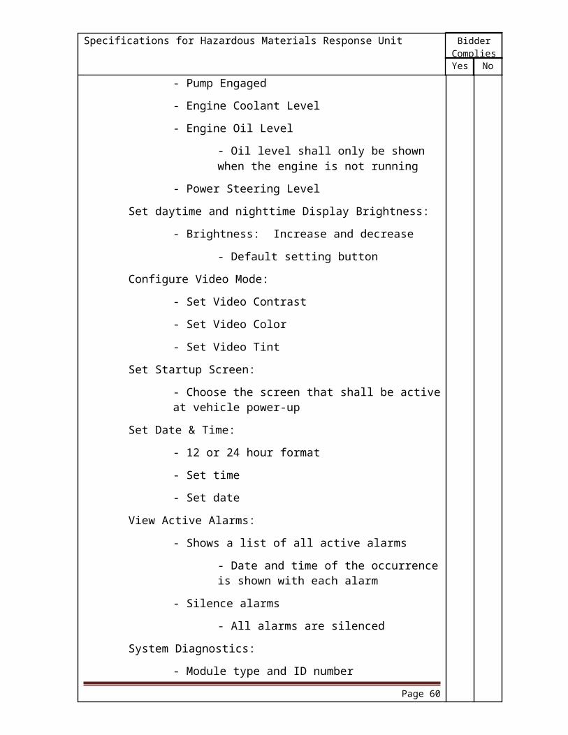
BidderComplies
NoYes
Specifications for Hazardous Materials Response Unit
Compartment Loading
The compartment shall be capable of holding 1,000 pounds (454 kg). The area over the frame rails shall be capable of holding an additional 2,000 pounds (908 kg).
Step Lights
A recessed light switch shall be provided on the rear bulkhead to control two (2) step lights installed over the rear step bumper.
INTERIOR FLOOR, WALLS, CEILING, COUNTER; MOBILE COMMANDInterior Floor Construction
The interior floor shall be constructed by welding a sheet to the cross sills of the substructure. There shall be a .63" exterior grade plywood sub-floor mounted directly to the welded sheet. Fastened to the .63" sub-floor shall be a .25" plywood overlay creating a finished subfloor for adhering the final floor material.
The final floor material shall be Lonseal Loncoin II FlecksGray Flecks non-slip vinyl installed on top of the plywood subfloor. Vertical mopboards shall be provided as needed.
Wall and Ceiling Construction
The walls and ceiling shall be insulated with a .25" double sided foil insulation and a 1.50" acoustical foam insulation.
Furring strips may be provided behind interior body walls and ceiling to allow space for the installation a cable management raceway system.
The interior sidewalls shall be covered with .50" plywood and Nevamar White Textured plastic laminate overlay.
The plywood .50" sub ceiling shall be covered in a gray ribbed loop pile fabric.
All angles and corners shall be properly trimmed for aesthetic purposes. All joints shall be covered with aluminum extrusions.
The horizontal counters shall be constructed of .75" thick plywood with a Nevamar White Textured plastic laminate overlay. The counters shall be free of any bolts or screws to provide a smooth surface.
Cable Management Raceway System
Two horizontal conduits shall be built behind the walls. The upper conduit shall house 12Vdc cabling as well as cabling for audio video, radio antenna, computer network, and telephone systems. Cabling shall pass through grommets when leaving the raceway and dropping to its termination point.
Page 60
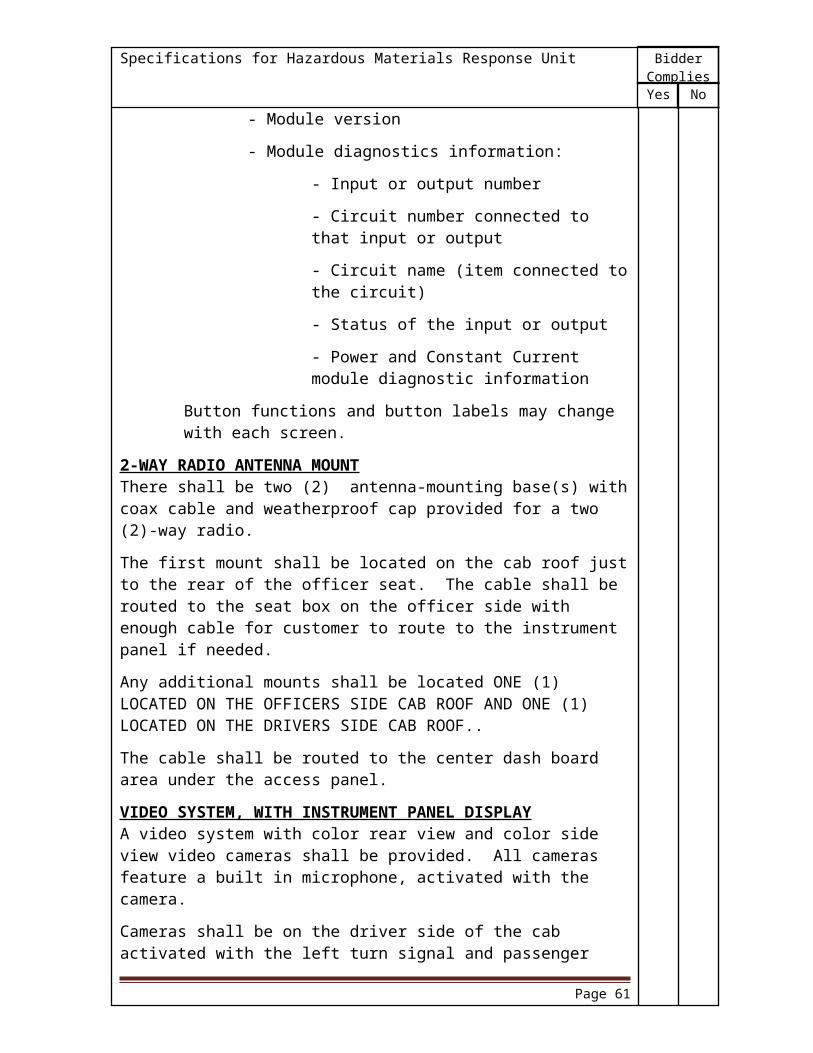
BidderComplies
NoYes
Specifications for Hazardous Materials Response Unit
The lower conduit shall house THHN cable for 120Vac systems. The 120-volt wiring shall be installed in flex conduit when exiting the raceway system in order to reduce electromagnetic interference with communication cabling.
Removable covers shall enable ease of access and permit future expansion/upgrade of outlets and circuits.
BODY WIDTHThe body width shall be 100.00" to the outside of the body sheet.
The rear compartment and interior walkway (if applicable) shall be increased by 4.00" from 40.00" wide to 44.00" wide with the clear door opening increasing accordingly. The side compartments shall remain the same depth.
If applicable, the hatch compartments shall be increased from 26.50" wide to 28.50" wide while the recessed walkway shall remain the same width.
All shelves, trays, tool boards, dividers, etc. shall be modified to appropriately to fit the new body width.
BODY MODIFICATIONThe body skirt height shall be lowered 5.31" ahead of the rear wheels.
INTERIOR CEILING LIGHTS, 3" CLEAR LEDThere shall be six (6) pair(s) of clear LED, 3.00" diameter, 12 volt lights recessed in the ceiling of the body interior.
The lights shall be equally distributed throughout the body interior providing light to the center walkway.
SWITCH FOR CEILING LIGHTSThe primary ceiling lights shall be actuated by one (1) 12 volt rocker switch located inside the body at the command entrance.
INTERIOR LIGHTINGInterior lighting shall consist of One (1) white LED, 12 volt light(s).
The light(s) shall be located PS SLIDE OUT.
These lights may be load managed when the parking brake is set.
SWITCH 2, INTERIOR LIGHTINGThe interior lighting located PASSENGER SIDE SLIDE OUT DUROLUMEN shall be controlled by one (1) 12 volt rocker switch located inside the body at the command entrance.
BENCH SEAT WITH SCBA BACKRESTThe interior shall be provided with two (2) flip up bench seat(s). The seat(s) shall be located passenger side slide - out.
Each seat shall be provided with a 24.00" wide x 15.00" deep cushion. A backrest shall be provided for each seat location. The backrest shall be constructed of the same material as the seat cushion.
Page 61

BidderComplies
NoYes
Specifications for Hazardous Materials Response Unit
The seat upholstery shall be made of black Imperial 1200 material.
An aluminum treadplate storage compartment 15.00" wide by 18.00" high shall be provided below the seat cushion(s). The seat cushion(s) mounted in adjacent locations shall be hinged together along the back to allow access to the storage area.
An automatic retractor type seat belt shall be furnished with each seat. An extension shall be provided with the seat belt so the male end can be easily grasped and the female end easily located while sitting in a normal position.
FOLD - DOWN BENCH SEAT WITH BACKRESTFold down bench seat(s) shall be provided in the interior of the body. The seat(s) shall accommodate a total of [Qty,] occupant(s) in the interior.
The seat(s) shall be located [Location].
Each seat location shall be provided with a continuous cushion. The cushion shall 18.00" deep and 24.00" wide for each occupant. A continuous backrest shall be provided for each seat location. The backrest shall be constructed of the same material as the seat cushion.
The seat upholstery shall be made of [Color, Seat Upholstery] material.
A single fold down seat iron shall be provided for each occupant. The seat iron shall be spring loaded keeping the cushion up while not in use. The bottom shall be covered with brushed stainless steel for a pleasant appearance when the seat is in the up position.
No seat belts shall be provided. A warning sign shall be placed in a visible area stating that this bench seat is not be occupied while the vehicle is in motion.
FOLD - DOWN BENCH SEAT WITH BACKRESTThe interior shall be provided with four (4) fold down bench seat(s). The seat(s) shall be located In the body slide out.
Each seat shall be provided with a 24.00" wide x 18.00" deep cushion. A backrest shall be provided for each seat location. The backrest shall be constructed of the same material as the seat cushion.
The seat upholstery shall be made of black Tuff-Tex aterial.
A single fold down seat iron shall be provided for each cushion. The seat iron shall be spring loaded keeping the cushion up while not in use. The bottom shall be covered with brushed stainless steel for a pleasant appearance when the seat is in the up position.
An automatic retractor type seat belt shall be furnished with each seat. An extension shall be provided with the seat belt so the male end can be easily grasped and the female end easily located while sitting in a normal position.
Page 62
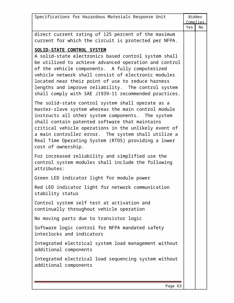
BidderComplies
NoYes
Specifications for Hazardous Materials Response Unit
AIR CONDITIONERInstalled in the roof of the body shall be an air conditioner with heating capability.
The unit shall be a low profile model with an aerodynamic white rooftop assembly. Unit's overall height shall be 10.63" high.
The air conditioner shall have cooling capacity of 15,000 BTUH. The heater shall have heating capacity of 5,600 BTUH.
The unit shall be 120 volt AC. The full load amperage draw shall be 16.4 amps in the heating mode or 14.8 amps in the cooling mode.
A total of one (1) shall be provided.
The air conditioner unit(s) shall be located walk-in section of the body.
A wall mounted digital thermostat capable of controlling the rooftop air conditioner with electric heat element shall control the unit.
FULL HEIGHT CABINETA wall cabinet shall be provided recessed into the rear wall of the body interior. The cabinet shall be approximately 55.25" (1,403 mm) high x 87.00" (2,210 mm) wide x 33.00" (838 mm) deep.
The cabinet shall be constructed of 0.75" (19 mm) plywood and covered with 5052-H32, 0.12" (3 mm) aluminum on both sides, bottom and backwall. The aluminum shall have a satin finish, and complement the interior trim.
The cabinet shall be divided into four (4) separate sections. Each section shall be approximately 20.00" (508 mm) wide x full height and full depth of the cabinet. A single, vertically hinged lap door with slam latch shall be provided for each section.
Each door shall be constructed of the same material as the cabinet and shall be covered with a dry erase material.
WALL CABINETThe body interior shall be furnished with wall cabinet(s). The cabinet(s) shall be 24.00" deep, with a maximum 30.00" wide. The cabinet height shall be determined by the mounting area in the interior. The cabinet(s) shall be constructed 5052-H32 .12 aluminum. The aluminum shall have a #10 white painted finish, and complement the interior trim.
The cabinet(s) shall have vertically hinged door(s) constructed of the same material as the cabinet. The door(s) shall be mounted to a continuous hinge on one edge of the cabinet. Each door shall have a slam latch preventing the door from opening when not in use.
There shall be one (1) cabinet(s) located to the left of the bench seat on the passenger side of the interior.
Page 63

BidderComplies
NoYes
Specifications for Hazardous Materials Response Unit
DRAWER ASSEMBLYThe body interior shall be furnished with cabinet drawer assemblies. The drawers shall be mounted in a vertical configuration, and capable of holding 250 pounds each.
The clear dimensions of the top cabinet drawer shall be 12.25" high x 21.00" deep. Mounted below the top drawer shall be the second drawer. The clear dimensions of the second cabinet drawer shall be 4.25" high x 21.00" deep. Below the second drawer shall be the third drawer. The clear dimensions of the third cabinet drawer shall be 2.25" high x 21.00" deep. All drawers shall be the same width, and not exceed 24.00".
The drawers shall be mounted in a cabinet housing constructed of light gray powder coated aluminum with anodized aluminum frames. The housing shall be 24.00" deep, and completely enclose the drawers.
A full-length aluminum extruded rail shall be provided at the top edge of each drawer. This rail shall act as the latching mechanism as well as the handle for each drawer.
When space permits the cabinet(s) shall be provided with a radius edge. The edging shall provide a uniform finished interior appearance.
The cabinet(s) shall be located Under the drivers side cab desk for a total quantity of one (1) in the body interior.
SLIDE-OUT MODULEThere shall be a one (1) slide-out module(s) above the drivers side exterior compartments. The finished slide-out module interior width shall be 84.00" (2134 mm) . The body height selected shall determine the unfinished interior height of the module. The module shall extend 30.00" (762 mm) from the body.
The slide-out module shall be operable with an interior or exterior control. The interior control shall have a lockout feature. The lockout feature shall prevent operation of the exterior control while someone is inside the body. The slide-out module control shall be tied to the parking brake. Only allowing the module to operate while the parking brake is engaged.
There shall be one (1) 4.00" (102 mm) red LED warning light installed on each side of the exterior of the slide-out module. The light shall be automatically enabled when the module is in the extended position.
The slide-out module shall extend and retract using two (2) hydraulic cylinders. The cylinders shall be connected to provide a uniform seal when the module is extended or retracted.
The slide-out module shall utilize three (3) seals in the extended and retracted positions for a weatherproof seal.
AWNING MOUNTING ENCLOSUREThere shall be one (1) enclosure(s) provided to mount the awning(s) above the body roof. The enclosure(s) shall be located passenger side.
Page 64

BidderComplies
NoYes
Specifications for Hazardous Materials Response Unit
The enclosure(s) shall follow the contour of the body roof line providing a clean integral appearance. There shall be a full length aluminum treadplate access cover provided creating a top of the enclosure. The remaining portion of the enclosure shall be finished to match the body exterior paint color.
AWNINGA roll-up style awning made of a fire retardant type material shall be supplied. The awning shall be stored in a metal housing on the side of the body when not in use. When fully extended, the awning shall be self supported without the use of poles extending to the ground. Lift handles shall be provided for leverage to raise the awning. A slider bar shall be provided to raise the arms out of the way for a clear path when walking under the awning.
The awning shall be the full length of the body. The awning shall extend out approximately (8) eight feet from the body. The color shall be tan.
The awning shall be installed passenger side.
A total of one (1) shall be supplied.
ROOF ACCESS LADDERA roof access ladder shall be provided at the rear of the body on the Drivers rear side. The ladder handrails shall be constructed out of 1.25" (3 mm) heavy-walled aluminum tubing that is covered with a black, heat-resistant, powder coated finish. Each step shall have a flat non-skid surface that is 3.00" (76 mm) deep x 15.50" (394 mm) wide. A swing-out and down extension section at the bottom of the ladder shall be provided.
SHELVINGCompartment D1 and P1 shall include 62.00" deep shelving.
The construction shall consist of .188" thick aluminum formed to provide a 2.00" high wall around the perimeter.
The corners shall be welded to provide a rigid unit.
The shelving shall be secured within the compartment, by means of adjustable threaded fasteners. These fasteners shall slide in an extruded aluminum track, to provide height adjustment.
There shall be six (6) provided.
ONE WAY UTILITY TRAYA 110.00" slide-out utility type tray shall be provided in the rear compartment.
The capacity rating shall be 500 pounds minimum in the extended position.
Interior tray dimensions shall be approximately 110.00" long x 3.00" deep.
Tray shall slide out in one (1) direction only; two-thirds of its length.
The construction shall consist of .188" thick aluminum for the tray bottom and end, and special aluminum extrusions for the tray sides, front, and tracks.
Page 65

BidderComplies
NoYes
Specifications for Hazardous Materials Response Unit
Corners shall be welded to form a rigid unit.
Tray shall be supported with a minimum of six (6) ball bearing rollers; each rated for a minimum 500 pound load.
Automatic locks shall be provided for both the in and out tray positions.
There shall be one (1) provided.
R1.
TWO-WAY UTILITY TRAYA two-way slide-out utility type tray shall be provided.
The capacity rating shall be 500 pounds minimum in the extended position.
Interior tray dimensions shall be approximately 85.00" long x 3.00" deep.
Tray shall slide out to either side of the vehicle; approximately two-thirds of its length.
The construction shall consist of .188" thick aluminum for the tray bottom, and special aluminum extrusions for the tray sides, end, and tracks.
Corners shall be welded to form a rigid unit.
Tray shall be supported with a minimum of eight (8) ball bearing rollers; each rated for a minimum 500 pound load.
Automatic locks shall be provided for both the in and out tray positions.
There shall be one (1) provided.
P2.
REAR BUMPERA rear bumper shall be provided that is an integral part of the rear body substructure.
The bumper shall be approximately 13.00" deep x 90.00" wide.
The bumper shall have an aluminum treadplate deck mounted to the frame providing a stepping surface.
A kickplate shall be provided above the bumper extending up on the rear bulkheads appro-ximately 3.00"
TOW EYESTwo (2) rear painted tow eyes shall be located at the rear of the apparatus and shall be mounted directly to the chassis frame rails. The inner and outer edges of the tow eyes shall have a radius.
ELECTRIC DOOR LOCKSThere shall be ten (10) door(s) located all body doors equipped with electric locks. The switch for control shall be located rear body.
Page 66

BidderComplies
NoYes
Specifications for Hazardous Materials Response Unit
A keyed manual lock shall be located on each door. This manual key can unlock the door when the electricity is disconnected, and the electric locks are in the locked position. The key cannot be used to lock the door. All locks shall be keyed alike.
COMPARTMENT LIGHTINGThere shall be 11 compartments with LED compartment light strips. Each strip shall be centered vertically along the door framing. There shall be a minimum of one (1) light per compartment. The compartments with these strip lights shall be located all body compartments.
Any remaining compartments shall include 6.00" diameter light in each enclosed compartment. Each light shall have a number 1076 one filament, two wire bulb.
Opening the compartment door shall automatically turn the compartment lighting on.
RUB RAILBottom edge of the side compartments shall be trimmed with a bright aluminum extruded rub rail.
Trim shall be approximately 2.12" high with 1.38" flanges turned outward for rigidity.
The rub rails shall not be an integral part of the body construction, which allows replacement in the event of damage.
BODY FENDER CROWNSStainless steel fender crowns shall be provided around the rear wheel openings. These fender crowns must be wide enough to prevent splashing onto the body from the 315/80R22.5 tires on a 30,000 lb rear axle.
A rubber welting shall be provided between the body and the crown to seal the seam and restrict moisture from entering.
A dielectric barrier shall be provided between the fender crown fasteners (screws) and the fender sheet metal to prevent corrosion.
REAR PULLOUT STEPA pull-out and down (camper style) step shall be installed below the tailboard step. The step surface when pulled out shall lower 5.00" and shall extend out from its nested position under the tailboard reducing the stepping distance from the ground to the top of the tailboard step.
This step shall be 8.00" deep and designed to fit in the mounting location. The stepping surface shall be bright aluminum treadplate. Slotted side support pieces of the pull-out portion of step shall be made out of .25" steel plate.
Page 67
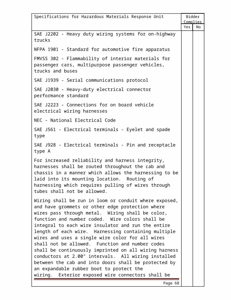
BidderComplies
NoYes
Specifications for Hazardous Materials Response Unit
AIR HORN SYSTEMTwo (2) air horns shall be provided and located, in the front bumper, recessed one on each side. The horn system shall be piped to the air brake system wet tank utilizing 0.38" tubing. A pressure protection valve shall be installed in-line to prevent loss of air in the air brake system.
AIR HORN CONTROLThe air horns shall be actuated by a foot switch on the officer's side and by the horn button in the steering wheel. The driver shall have the option to control the air horns or the chassis horns from the horn button by means of a selector switch located on the instrument panel.
ELECTRONIC SIRENThere shall be an electronic siren with noise canceling microphone provided.
Electronic siren head shall be recessed in the overhead console above the engine tunnel on the driver side.
Siren shall be actuated by a foot switch on the officer's side and by the horn button in the steering wheel. The driver shall have the option to control the siren or the chassis horns from the horn button by means of a selector switch.
SPEAKERA 200 watt speaker shall be provided. A chrome-plated grille shall be installed in front of the speaker.
The speaker(s) shall be recessed in the front bumper on the driver's side.
LIGHTBAR, CAB ROOFThere shall be a 77.00" LED lightbar mounted on the cab roof.
The lightbar shall include the following:
Two (2) red flashing LED modules facing forward. Two (2) blue flashing LED modules facing forward. Two (2) white flashing LED modules facing forward. Two (2) red flashing corner LED modules, one in each front corner. One (1) red flashing LED module facing the driver's side. One (1) red flashing LED module facing the officer's side.
All lenses shall be clear.
There shall be one (1) switch located in the cab on the switch panel to control this lightbar.
The white warning lights shall be disabled when the parking brake is applied.
The two (2) red flashing LED modules facing forward may be load managed when the parking brake is applied.
Page 68

BidderComplies
NoYes
Specifications for Hazardous Materials Response Unit
TRAFFIC LIGHT CONTROLLER, WIRING ONLYWiring only shall be provided for the traffic light controller remote mounted on the cab, drivers side cab roof.
The traffic light controller shall be activated by a cab switch with emergency master control.
The traffic light controller shall have no momentary activation switch.
The traffic light controller shall be disabled when the parking brake is applied.
The wiring terminals shall be clearly identified.
DNREC will provide the opticom to the dealer.
WARNING LIGHTS (Cab Face)Four (4) LED flashing warning lights shall be installed on the cab face, above the headlights, mounted in a common bezel.
The driver's side front outside warning light to be red.
The driver's side front inside warning light to be blue.
The passenger's side front inside warning light to be blue.
The passenger's side front outside warning light to be red.
All four (4) lights shall include a clear lens.
All four (4) lights shall be controlled by a lighted switch in the cab on the switch panel.
The inside lights may be load managed if colored or disabled if white, when the parking brake is set.
HEADLIGHT FLASHERThe high beam headlights shall flash alternately between the left and right side, with a control switch located on the cab instrument panel.
The flashing shall automatically cancel when the headlight switch is activated or when the parking brake is set.
SIDE ZONE LOWER LIGHTINGSix (6) LED flashing warning lights with bezels shall be located in the following positions:
Two (2) lights, one (1) each side on the bumper extension.
The side front lights to be red.
Two (2) lights, red.
The side middle lights to be red.
Two (2) lights, red.
Page 69

BidderComplies
NoYes
Specifications for Hazardous Materials Response Unit
The side rear lights to be red.
All six (6) lights shall include a clear lens.
All six (6) lights shall be controlled by a lighted switch on the cab switch panel.
REAR ZONE LOWER LIGHTINGTwo (2) LED flashing warning lights with bezels shall be located at the rear of the apparatus.
The driver's side rear light to be red.
The passenger's side rear light to be blue..
Both lights shall include a lens that is clear.
Both lights shall be controlled by a lighted switch on the switch panel.
WARNING LIGHTS (Rear and Side upper zones)Four (4) LED flashing warning lights shall be provided at the rear of the apparatus.
The side rear upper light on the driver's side to be red.
The rear upper light on the driver's side to be red.
The rear upper light on the passenger's side to be red.
The side rear upper light on the passenger's side to be red.
These lights shall include a lens that is clear.
One (1) switch located in the cab on the switch panel shall control these lights.
ELECTRICAL SYSTEM GENERAL DESIGN for ALTERNATING CURRENTThe following guidelines shall apply to the 120/240 VAC system installation:
General
Any fixed line voltage power source producing alternating current (ac) line voltage shall produce electric power at 60 cycles plus or minus five (5) cycles.
Except where superseded by the requirements of NFPA 1901, all components, equipment and installation procedures shall conform to NFPA 70, National Electrical Code (herein referred to as the NEC).
Line voltage electrical system equipment and materials included on the apparatus shall be listed and installed in accordance with the manufacturer's instructions. All products shall be used only in the manner for which they have been listed.
Grounding
Grounding shall be in accordance with Section 250-6 "Portable and Vehicle Mounted Generators" of the NEC. Ungrounded systems shall not be
Page 70

BidderComplies
NoYes
Specifications for Hazardous Materials Response Unit
used. Only stranded or braided copper conductors shall be used for grounding and bonding.
An equipment grounding means shall be provided in accordance with Section 250-91 (Grounding Conductor Material) of the NEC.
The grounded current carrying conductor (neutral) shall be insulated from the equipment grounding conductors and from the equipment enclosures and other grounded parts. The neutral conductor shall be colored white or gray in accordance with Section 200-6 (Means of Identifying Grounding Conductors) of the NEC.
In addition to the bonding required for the low voltage return current, each body and driving or crew compartment enclosure shall be bonded to the vehicle frame by a copper conductor. This conductor shall have a minimum amperage rating of 115 percent of the nameplate current rating of the power source specification label as defined in Section 310-15 (amp capacities) of the NEC. A single conductor properly sized to meet the low voltage and line voltage requirements shall be permitted to be used.
All power source system mechanical and electrical components shall be sized to support the continuous duty nameplate rating of the power source.
Operation
Instructions that provide the operator with the essential power source operating instructions, including the power-up and power-down sequence, shall be permanently attached to the apparatus at any point where such operations can take place.
Provisions shall be made for quickly and easily placing the power source into operation. The control shall be marked to indicate when it is correctly positioned for power source operation. Any control device used in the drive train shall be equipped with a means to prevent the unintentional movement of the control device from its set position.
A power source specification label shall be permanently attached to the apparatus near the operator's control station. The label shall provide the operator with the information detailed in Figure 19-4.10.
Direct drive (PTO) and portable generator installations shall comply with Article 445 (Generators) of the NEC.
Overcurrent protection
The conductors used in the power supply assembly between the output terminals of the power source and the main over current protection device shall not exceed 144 inches. (3658 mm) in length.
For fixed power supplies, all conductors in the power supply assembly shall be type THHW, THW, or use stranded conductors enclosed in nonmetallic liquid
Page 71

BidderComplies
NoYes
Specifications for Hazardous Materials Response Unit
tight flexible conduit rated for a minimum of 194 degrees Fahrenheit (90 degrees Celsius).
For portable power supplies, conductors located between the power source and the line side of the main overcurrent protection device shall be type SO or type SEO with suffix WA flexible cord rated for 600-volts at 194 degrees Fahrenheit (90 degrees Celsius).
Wiring Methods
Fixed wiring systems shall be limited to the following:
- Metallic or nonmetallic liquid tight flexible conduit rated at not less than 194 degrees Fahrenheit (90 degrees Celsius)
or
- Type SO or Type SEO cord with a WA suffix, rated at 600 volts at not less than 194 degrees Fahrenheit (90 degree Celsius)
Electrical cord or conduit shall not be attached to chassis suspension components, water or fuel lines, air or air brake lines, fire pump piping, hydraulic lines, exhaust system components, or low voltage wiring. In addition the wiring shall be run as follows:
- Separated by a minimum of 12 inches (305 mm), or properly shielded, from exhaust piping
- Separated from fuel lines by a minimum of six (6) inches (152 mm) distance.
Electrical cord or conduit shall be supported within six (6) inches (152 mm) of any junction box and at a minimum of every 24 inches (610 mm) of continuous run. Supports shall be made of nonmetallic materials or corrosion protected metal. All supports shall be of a design that does not cut or abrade the conduit or cable and shall be mechanically fastened to the vehicle.
Wiring Identification
All line voltage conductors located in the main panel board shall be individually and permanently identified. The identification shall reference the wiring schematic or indicate the final termination point. When prewiring for future power sources or devices, the unterminated ends shall be labeled showing function and wire size.
Wet Locations
All wet location receptacle outlets and inlet devices, including those on hardwired remote power distribution boxes, shall be of the grounding type provided with a wet location cover and installed in accordance with Section 210-7 "Receptacles and Cord Connections" of the NEC.
Page 72

BidderComplies
NoYes
Specifications for Hazardous Materials Response Unit
All receptacles located in a wet location shall be not less than 24 inches (610 mm) from the ground. Receptacles on off-road vehicles shall be a minimum of 30 inches (762 mm) from the ground.
The face of any wet location receptacle shall be installed in a plane from vertical to not more than 45 degrees off vertical. No receptacle shall be installed in a face up position.
Dry Locations
All receptacles located in a dry location shall be of the grounding type. Receptacles shall be not less than 30 inches (762 mm) above the interior floor height.
All receptacles shall be marked with the type of line voltage (120-volts or 240-volts) and the current rating in amps. If the receptacles are direct current, or other than single phase, they shall be so marked.
Listing
All receptacles and electrical inlet devices shall be listed to UL 498, Standard for Safety Attachment Plugs and Receptacles, or other appropriate performance standards. Receptacles used for direct current voltages shall be rated for the appropriate service.
Electrical System Testing
The wiring and associated equipment shall be tested by the apparatus manufacturer or the installer of the line voltage system.
The wiring and permanently connected devices and equipment shall be subjected to a dielectric voltage withstand test of 900-volts for one (1) minute. The test shall be conducted between live parts and the neutral conductor, and between live parts and the vehicle frame with any switches in the circuit(s) closed. This test shall be conducted after all body work has been completed.
Electrical polarity verification shall be made of all permanently wired equipment and receptacles to determine that connections have been properly made.
Operational Test per Current NFPA 1901 Standards
The apparatus manufacturer shall perform the following operation test and ensure that the power source and any devices that are attached to the line voltage electrical system are properly connected and in working order. The test shall be witnessed and the results certified by an independent third-party certification organization.
The prime mover shall be started from a cold start condition and the line voltage electrical system loaded to 100 percent of the nameplate rating.
Page 73

BidderComplies
NoYes
Specifications for Hazardous Materials Response Unit
The power source shall be operated at 100 percent of its nameplate voltage for a minimum of two (2) hours unless the system meets category certification as defined in the current NFPA 1901 standard.
Where the line voltage power is derived from the vehicle's low voltage system, the minimum continuous electrical load as defined in the current NFPA 1901 standard shall be applied to the low voltage electrical system during the operational test.
25KW SINGLE PHASE GENERATORThe apparatus shall be equipped with a complete electrical power system. The wiring and generator installation shall conform to the present National Electrical Code Standards of the National Fire Protection Association. The installation shall be designed for continuous operation without overheating and undue stress on components.
The generator shall be a single phase, four (4)-wire, 25kW driven by a transmission "power takeoff" attached to the side of the transmission.
Generator performance shall meet the American National Standards Institute (ANSI) C84.1-1982 voltage requirement as utilized from the receptacle.
Generator shall have a built in automatic voltage control.
Generator shall have a NEMA MG21 rating.
- Continuous Duty Rating: 25,000 watts
- Phase: Single
- Nominal Cycles: 60 hertz
- Nominal Amp Rating: 104 at 240-volts
- Engine Speed at Engagement: Idle
- Engine Speed Engaged: 1118
- Generator RPM: 1800 rpm
The output of the generator shall be controlled by an electronic governor. The governor shall be programmed so the generator's output is at 60 hertz.
The main chassis transmission PTO shall power the generator. A stainless steel splash guard shall be installed to reduce the amount of road spray on this frame-mounted PTO generator.
The generator shall be operable in the stationary mode with a shift control located inside the cab with an indicator light to note engagement. For safety, the automatic high idle shall be activated through interlocks only after the chassis parking brake control is in the park position, the generator PTO transmission has made a complete shift and the truck transmission is in neutral.
Page 74

BidderComplies
NoYes
Specifications for Hazardous Materials Response Unit
An electric/hydraulic valve shall supply hydraulic fluid to the clutch engagement unit provided on the chassis PTO drive.
To properly monitor the generator performance and load demands during operation, the generator shall be equipped with a full instrument and control package. This panel shall be mounted adjacent to the load center. The following instruments shall be installed in the panel:
- One (1) Voltmeter
- Two (2) Ammeters
- One (1) Frequency Meter
- One (1) Hour Meter
- One (1) "Power On" Green Indicator Light
- One (1) PTO Engagement Indicator Light
- Two (2) Fuse Holders: With two (2) amp fuses for gauge protection
The meter and indicators shall be installed near eye level in the compartment. Instruments shall be flush mounted in an appropriate sized weatherproof electrical enclosure. All instruments used shall be accurate within +/- two (2) percent.
The system shall be installed by highly qualified electrical technicians to assure the required level of safety and protection to the fire apparatus operators. The wiring, electrical fixtures and components shall be to the highest industry quality standards available on the domestic market. The equipment shall be the type designed for mobile installations subject to vibration, moisture and severe continuous usage.
All electrical wiring from the load center shall be fine stranded copper S.O. type with a 600 volt jacket. The wire shall be sized to the load and circuit breaker rating. The wire size shall be ten (10)-gauge on 30 amp circuits, 12-gauge on 20 amp circuits and 14-gauge on 15 amp circuits. The S.O. cable shall be run in corner areas and extruded aluminum pathways built into the body for easy access. Any S.O. cord not run in an enclosed raceway or cable tray shall have an additional abrasion resistant covering.
The main load center shall have circuit breakers rated to load demand.
Individual breakers shall be provided for all receptacles to isolate a tripped breaker from affecting any other on-line equipment.
GENERATOR LOCATIONThe generator shall be mounted under the body between the frame rails.
GENERATOR STARTA switch shall be located on the cab instrument panel to engage the generator.
Page 75

BidderComplies
NoYes
Specifications for Hazardous Materials Response Unit
CIRCUIT BREAKER PANELThe circuit breaker panel shall be located tbd.
LIGHT MAST MOUNTING AREA ON CAB ROOFA light mast, roof mounted elevated lighting system, shall be provided and mounted by the customer. The apparatus manufacturer shall provide reinforcement, air line supply from the brake system and 120/240 volt wiring to the light mast mounting area. Wiring and air lines shall terminate under the roof line in the reinforced area. .
Unit shall mount on an external roof surface area 83.00" long x 43.00" wide x 12.00" high on the cab.
Mast shall be operated with a 12-volt DC and 20 psi regulated air from the chassis air sys-tem.
Weight of the unit shall not exceed 180 pounds.
ELECTRIC CORD REEL MOUNTING PROVISIONSupports and the appropriate size 12 volt wiring shall be provided for the mounting of a customer installed electrical cord reel. This shall include the wiring from the reel mounting area to the circuit breaker in the load center.
The circuit provided for the customer installed reel shall be protected for a 30 amps, and 120/240 volts. The reel shall be configured for a capacity of tbd feet of 10/3 cord.
A total of two (2) cord reels shall be installed by the customer in the hatch above D2 and P2.
POWER OUTLET STRIPA six (6) place power outlet strip shall be provided. The outlet strip shall contain 120 volt 20 amp straight blade receptacles.
A total of four (4) receptacles shall be provided to be determined.
LOOSE EQUIPMENTThe following equipment shall be furnished with the completed unit:
- Two (2) bags of chrome, stainless steel, or cadmium plated screws, nuts, bolts and washers, as used in the construction of the unit
PAINTThe exterior custom cab and body painting procedure shall consist of a seven (7) step finishing process as follows:
1. Manual Surface Preparation - All exposed metal surfaces on the custom cab and body shall be thoroughly cleaned and prepared for painting. Surfaces that shall not be painted include all chrome plated, polished stainless steel, anodized aluminum and bright aluminum treadplate. Each imperfection on the exterior metal surface shall be removed or filled and then sanded smooth for a smooth appearance. All seams shall be sealed before painting.
Page 76

BidderComplies
NoYes
Specifications for Hazardous Materials Response Unit
2. Chemical Cleaning and Treatment - The metal surfaces shall be properly cleaned using a high pressure and high temperature cleaning system. Surfaces are chemically cleaned to remove all dirt, oil, grease and metal oxides to ensure the subsequent coatings bond well. An ultra pure water final rinse shall be applied to all metal surfaces at the conclusion of the metal treatment process.
3. Primer/Surfacer Coats - A two (2) component urethane primer/surfacer shall be hand applied to the chemically treated metal surfaces to provide a strong corrosion protective base coat and to smooth out the surface.
4. Hand Sanding - The primer/surfacer coat shall be lightly sanded to an ultra smooth finish.
5. Sealer Primer Coat - A two (2) component sealer primer coat shall be applied over the sanded primer.
6. Topcoat Paint - Urethane base coat shall be applied to opacity for correct color matching.
7. Clearcoat - Two (2) coats of an automotive grade two (2) component urethane shall be applied. Lap style doors shall be clear coated to match the body. Roll-up doors shall not be clear coated and the standard roll-up door warranty shall apply.
All removable items such as brackets, compartment doors, door hinges, trim, etc. shall be removed and painted separately to insure paint behind all mounted items. Body assemblies that can not be finish painted after assembly shall be finish painted before assembly.
The cab and body shall be two-tone, with the upper section painted White and lower section of the cab and body painted Metallic.
PAINT - ENVIRONMENTAL IMPACTContractor shall meet or exceed all current State (his) regulations concerning paint operations. Pollution control shall include measures to protect the atmosphere, water and soil. Controls shall include the following conditions:
- Topcoats and primers must be chrome and lead free.
- Metal treatment chemicals must be chrome free. The wastewater generated in the metal treatment process must be treated on-site to remove any other heavy metals.
- Particulate emission collection from sanding operations must have a 99.99 percent efficiency factor.
- Particulate emissions from painting operations must be collected by a dry filter or water wash process. If the dry filter means is used, it must have an efficiency rating of 98 percent. Water wash systems must be 99.97 percent efficient.
- Water from water wash booths must be reused. Solids shall be removed mechanically on a continual basis to keep the water clean.
Page 77

BidderComplies
NoYes
Specifications for Hazardous Materials Response Unit
- Paint wastes are disposed of in an environmentally safe manner. They are used as fuel in kilns used in the cement manufacturing process - thereby extracting energy from a waste material.
- Empty metal paint containers must be cleaned, crushed and recycled to recover the metal.
- Solvents used in cleanup operations must be collected, recycled on-site, or sent off-site for distillation and returned for reuse. Residue from the distillation operation shall be used as fuel in off-site cement kilns.
Additionally, the finished apparatus shall not be manufactured with or contain products that have ozone depleting substances. Contractor shall, upon demand, present evidence that his manufacturing facility meets the above conditions and that it is in compliance with his State EPA rules and regulations.
PAINT CHASSIS FRAME ASSEMBLYThe chassis frame assembly shall be painted black before the installation of the cab and body, and before installation of the engine and transmission assembly, air brake lines, electrical wire harnesses, etc. Components that are included with the chassis frame assembly that shall be painted black are frame rails, cross members, axles, suspension, steering gear, fuel tank, body substructure supports, miscellaneous mounting brackets, etc.
PAINT, FRONT WHEELSAll wheel surfaces, inside and outside, shall be provided with Paint, Wheels.
PAINT, COMPARTMENT INTERIORInterior of compartmentation shall be painted with a gray spatter type paint.
REFLECTIVE BANDReflective stripes shall be provided across the front of the vehicle and along the sides of the body. The reflective band shall consist of a 1.00" yellow stripe at the top with a 1.00" gap and a 6.00" yellow stripe on the bottom.
The reflective band provided on the cab face shall be below the headlights on the fiberglass.
CHEVRON STRIPING, REARThere shall be alternating chevron striping located on the rear-facing vertical surface of the apparatus. The entire rear surface shall be covered.
The colors shall be red and fluorescent yellow green diamond grade.
Each stripe shall be 6.00" in width.
This shall meet the requirements of NFPA 1901, 2009 edition, which states that 50% of the rear surface shall be covered with chevron striping.
REFLECTIVE STRIPE, CAB DOORSA 6.00" x 16.00" yellow reflective stripe shall be provided across the interior of each cab door. The stripe shall be located approximately 1.00" up from the bottom, on the door panel.
Page 78

BidderComplies
NoYes
Specifications for Hazardous Materials Response Unit
This stripe shall meet the NFPA 1901 requirement.
LETTERINGOne (1) to twenty (20) reflective lettering, 3.00" high, with outline and shade shall be provided.
LETTERINGThere shall be reflective lettering, 10.00" high, with outline and shade provided. There shall be six (6) letters provided.
LETTERINGTwenty-one (21) to forty (40) reflective lettering, 5.00" high, with outline and shade shall be provided.
LETTERINGThere shall be reflective lettering, 9.00" high, with outline and shade provided. There shall be 12 letters provided.
MANUAL, FIRE APPARATUS PARTSTwo (2) custom parts manuals for the complete fire apparatus shall be provided in hard copy with the completed unit.
SERVICE PARTS INTERNET SITEThe service parts information included in this manual is also available on the Internet.
MANUALS, CHASSIS SERVICETwo (2) chassis service manuals containing parts and service information on major components shall be provided with the completed unit.
CD MANUAL, CHASSIS OPERATIONTwo (2) CD format chassis operation manuals shall be provided.
ONE (1) YEAR MATERIAL AND WORKMANSHIPEach new piece of apparatus shall be provided with a minimum one (1) year basic apparatus material and workmanship limited warranty. The warranty shall cover such portions of the apparatus built by the manufacturer as being free from defects in material and workmanship that would arise under normal use and service.
A copy of the warranty certificate shall be submitted with the bid package. (no exception).
THREE (3) YEAR MATERIAL AND WORKMANSHIPThe new chassis shall be provided with a three (3) year material and workmanship limited warranty. The warranty shall cover such portions of the chassis built by the manufacturer as being free from structural failures caused by defects in material and workmanship that would arise under normal use and service.
A copy of the warranty certificate shall be submitted with the bid package (No Exception).
Page 79

BidderComplies
NoYes
Specifications for Hazardous Materials Response Unit
ENGINE WARRANTY A five (5) year limited engine warranty shall be provided. A copy of the warranty certificate shall be submitted with the bid package.
STEERING GEAR WARRANTY A three (3) year limited steering gear warranty shall be provided. A copy of the warranty certificate shall be submitted with the bid package.
FIFTY (50) YEAR STRUCTURAL INTEGRITYThe chassis frame and crossmembers shall be provided with a fifty (50) year material and workmanship limited warranty. The warranty shall cover the chassis frame and crossmembers as being free from defects in material and workmanship that would arise under normal use and service.
A copy of the warranty certificate shall be submitted with the bid package.
FRONT AXLE THREE (3) YEAR MATERIAL AND WORKMANSHIP WARRANTYIndependent front suspension shall be provided with a three (3) year material and workmanship limited warranty. The manufacturer's warranty shall provide that the independent front suspension and steering gears be free from any defect related to material and workmanship on the portion of the apparatus built by the manufacturer that would arise under normal use and service. A copy of the warranty certificate shall be submitted with the bid package (No Exception).
REAR AXLE TWO (2) YEAR MATERIAL AND WORKMANSHIP WARRANTYA 2 year axle limited warranty shall be provided.
TEN (10) YEAR STRUCTURAL INTEGRITY The new cab shall be provided with a ten (10) year material and workmanship limited warranty. The warranty shall cover such portions of the cab built by the manufacturer as being free from structural failures caused by defects in material and workmanship that would arise under normal use and service.
A copy of the warranty certificate shall be submitted with the bid package.
TEN (10) YEAR PAINT AND CORROSION Each new piece of apparatus shall be provided with a ten (10) year paint and corrosion limited warranty on the apparatus cab. The warranty shall cover painted exterior surfaces of the body to be free from blistering, peeling, corrosion, or any other adhesion defect caused by defective manufacturing methods or paint material selection that would arise under normal use and service.
A copy of the warranty certificate shall be submitted with the bid package.
Page 80

BidderComplies
NoYes
Specifications for Hazardous Materials Response Unit
TRANSMISSION WARRANTYThe transmission shall have a five (5) year/unlimited mileage warranty covering 100 percent parts and labor. The warranty is to be provided by transmission supplier and not the apparatus builder.
TRANSMISSION COOLER WARRANTYThe transmission cooler shall carry a five (5) year parts and labor warranty (exclusive to the transmission cooler). In addition, a collateral damage warranty shall also be in effect for the first three (3) years of the warranty coverage and shall not exceed $10,000 per occurrence. A copy of the warranty certificate shall be submitted with the bid package.
FIFTEEN (15) YEAR STRUCTURAL INTEGRITY Each new piece of apparatus shall be provided with a fifteen (15) year material and workmanship limited warranty on the apparatus body. The warranty shall cover such portions of the apparatus built by the manufacturer as being free from defects in material and workmanship that would arise under normal use and service.
A copy of the warranty certificate shall be submitted with the bid package.
TEN (10) YEAR PAINT AND CORROSION Each new piece of apparatus shall be provided with a ten (10) year paint and corrosion limited warranty on the apparatus body. The warranty shall cover painted exterior surfaces of the body to be free from blistering, peeling, corrosion, or any other adhesion defect caused by defective manufacturing methods or paint material selection that would arise under normal use and service.
A copy of the warranty certificate shall be submitted with the bid package.
ONE (1) YEAR MATERIAL AND WORKMANSHIP The graphic lamination shall be provided with a one (1) year material and workmanship limited warranty. The warranty shall cover the graphic lamination as being free from defects in material, workmanship, fading, and deterioration that would arise under normal use and service.
A copy of the warranty certificate shall be submitted with the bid package.
ENGINE INSTALLATION CERTIFICATIONThe fire apparatus manufacturer shall provide a certification, along with a letter from the engine manufacturer stating they approve of the engine installation in the bidder's chassis. The certification shall be provided at the time of bid.
POWER STEERING CERTIFICATION The fire apparatus manufacturer shall provide a certification stating the power steering system as installed meets the requirements of the component supplier. The certification shall be provided at the time of bid.
Page 81

BidderComplies
NoYes
Specifications for Hazardous Materials Response Unit
CAB INTEGRITY CERTIFICATIONThe fire apparatus manufacturer shall provide, at the time of bid, a cab integrity certification. Testing shall meet or exceed the requirements below:
- European Occupant Protection Standard ECE Regulation No.29.
- SAE J2422 Cab Roof Strength Evaluation - Quasi-Static Loading Heavy Trucks.
- SAE J2420 COE Frontal Strength Evaluation - Dynamic Loading Heavy Trucks.
Failure of the bidder to be able to comply with any portion of the cab integrity certification could lead to the proposal being determined non-responsible.
CAB DOOR DURABILITY CERTIFICATIONRobust cab doors help protect occupants. Cab doors shall survive a 200,000 cycle door slam test where the slamming force exceeds 20 G's of deceleration. The bidder shall certify that the sample doors similar to those provided on the apparatus have been tested and have met these criteria without structural damage, latch malfunction, or significant component wear.
WINDSHIELD WIPER DURABILITY CERTIFICATIONVisibility during inclement weather is essential to safe apparatus performance. Windshield wipers shall survive a 3 million cycle durability test in accordance with section 6.2 of SAE J198 Windshield Wiper Systems - Trucks, Buses and Multipurpose Vehicles. The bidder shall certify that the wiper system design has been tested and that the wiper system has met these criteria.
ELECTRIC WINDOW DURABILITY CERTIFICATIONCab window roll-up systems can cause maintenance problems if not designed for long service life. The window regulator design shall complete 30,000 complete up-down cycles and still function normally when finished. The bidder shall certify that sample doors and windows similar to those provided on the apparatus have been tested and have met these criteria without malfunction or significant component wear.
SEAT BELT ANCHOR STRENGTHSeat belt attachment strength is regulated by Federal Motor Vehicle Safety Standards and should be validated through testing. Each seat belt anchor design shall withstand 3000 lb of pull on both the lap and shoulder belt in accordance with FMVSS 571.210 Seat Belt Assembly Anchorages. The bidder shall certify that each anchor design was pull tested to the required force and met the appropriate criteria.
SEAT MOUNTING STRENGTHSeat attachment strength is regulated by Federal Motor Vehicle Safety Standards and should be validated through testing. Each seat mounting design shall be tested to withstand 20 G's of force in accordance with FMVSS 571.207 Seating Systems. The bidder shall certify that each seat mount and cab
Page 82

BidderComplies
NoYes
Specifications for Hazardous Materials Response Unit
structure design was pull tested to the required force and met the appropriate criteria.
CAB DEFROSTER CERTIFICATIONVisibility during inclement weather is essential to safe apparatus performance. The defroster system shall clear the required windshield zones in accordance with SAE J381 Windshield Defrosting Systems Test Procedure And Performance Requirements - Trucks, Buses, And Multipurpose Vehicles. The bidder shall certify that the defrost system design has been tested in a cold chamber and passes the SAE J381 criteria.
CAB HEATER CERTIFICATIONGood cab heat performance and regulation provides a more effective working environment for personnel, whether in-transit, or at a scene. The cab heaters shall warm the cab 75 F from a cold-soak, within 30 minutes when tested using the coolant supply methods found in SAE J381. The bidder shall certify that a substantially similar cab has been tested and has met these criteria.
CAB AIR CONDITIONING PERFORMANCE CERTIFICATION Good cab air conditioning temperature and air flow performance keeps occupants comfortable, reduces humidity, and provides a climate for recuperation while at the scene. The cab air conditioning system shall cool the cab from a heat-soaked condition at 100 degrees Fahrenheit to an average of 67 degrees Fahrenheit in 30 minutes. The bidder shall certify that a substantially similar cab has been tested and has met these criteria.
AMP DRAW REPORTThe bidder shall provide, at the time of bid and delivery, an itemized print out of the expected amp draw of the entire vehicle's electrical system.
The manufacturer of the apparatus shall provide the following:
1) Documentation of the electrical system performance tests.
2) A written load analysis, which shall include the following:
A) The nameplate rating of the alternator.
B) The alternator rating under the conditions specified per:
Applicable NFPA 1901 or 1906 (Current Edition).
C) The minimum continuous load of each component that is specified per:
Applicable NFPA 1901 or 1906 (Current Edition).
D) Additional loads that, when added to the minimum continuous load, determine the total connected load.
E) Each individual intermittent load.
Page 83

BidderComplies
NoYes
Specifications for Hazardous Materials Response Unit
REQUESTED OPTIONS FOR PRICING
1. FRONT SUSPENSION Front springs shall be a heavy-duty, taper leaf design, 54.00" long by 4.00" wide, with a ground rating of 21,500 lb.
Kaiser spring pins shall be provided with double figure-eight grease grooves and a layer of electroless nickel plating, 1.0 mil thick around the entire pin. The bushing that holds the spring pin in place shall also have a grease groove.
2. GREEN STAR TECHNOLOGY
An Auxiliary Power Unit (APU) – Idle Reduction Technology System that will automatically Shut the chassis engine off and switch to the APU when the PTO’s are not being used. The APU takes over all electrical loads of vehicle, including the auxiliary climate control system.
3. TELESCOPIC TOWER LIGHT AND CAMERA SYSTEM
Factory installed Will-Burt NS 4.5 9000 OPT with 6x1500W/240VAC FRC Optimum Light Fixtures, wired handheld kit, DC and AC control cables and Wonwoon Camera System w/Telipix Control
OR NS 4.5 (15’ extended) with 6 x Spectra LED Fixtures all other accessories the same
Page 84