Embed Size (px)
Citation preview

13th North American Waste to Energy Conference May 23-25, 2005, Orlando, Florida USA
NAWTEC13-3165
Pulse-jet Baghouse Optimization in WTE:
Meeting the Challenges of the Future
Jeff Ladwig Robin Linton GE Ener�y
8800 East 63' Street Kansas City, Missouri 64133
800-821-2222
Abstract
Like many coal-fired power plants today, the waste-to-energy
(WTE) industry is faced with a number of challenges
including the need to maximize plant output, lower outlet
emissions and increase plant efficiencies. Within WTE,
there's also been a move from reverse-air baghouses to pulse
jet collectors due to lower initial capital costs and the ability to
operate pUlse-jet collectors at higher air-to-cloth ratios (3-4: I),
allowing for a smaller housing footprint. However, the
majority of today's pUlse-jet collectors utilize an off-line
cleaning mode where modules are taken out of service and
pulsed to lower the differential pressure. There are inherent
advantages in switching from an off-line cleaning mode to an
on-line cleaning mode. This paper discusses the idea of using
the fabric filter as a damper and stabilizing draft through the
baghouse and boiler. It also outlines the use of pleated filter
element (PFE) technology to address increased production
concerns, and the need for lower outlet emissions.
Combustion System Operating Parameters
In the operation of a combustion system, the ill (induced
draft) fan is normally controlled with a pressure transducer
located in the combustion area. The normal draft used to
control the combustion process can be as low as .25" w.c. to as
much as 3" w.c. The draft at the inlet is used to control the fan
damper position, maintaining constant airflow through the
system. Since the system has components that create pressure
drop, this draft is fairly constant to airflow volume.
157
Off Line Pulse-jet Cleaning in a Combustion Dust
Collection System
Off line cleaning is the typical mode of cleaning in a pulse-jet
collector. This method of cleaning often causes fluctuations in
pressure drop in the baghouse, which in tum causes an adverse
effect on the draft in the combustion system. When a
compartment is removed from service for cleaning, the
pressure drop across the baghouse increases and the result is a
reduction of negative pressure at the pressure transducer. This
causes the fan damper to open to balance the flow to the "set"
negative pressure in the control area. Once the compartment is
cleaned and returned to service, the lower differential of that
compartment causes a lower system differential, resulting in a
negative pressure that is too high at the pressure transducer
signal. This often causes heat to be removed from the process
resulting in higher temperatures and airflows at the baghouse.
This change in system pressure causes changes in draft
volume until the fan damper reacts to the pressure transducer
signal. This fluctuation is a result of the removal of a
compartment from service.
Moving to On Line Cleaning
In pulse-jet collectors, the cleaning function rearranges the
dustcake and some dust is removed. The result in the
rearrangement of the dustcake is a reduction in differential
pressure for the most recently cleaned row of filter bags. The
displaced dust that falls off the ends of the bags is subject to
the internal velocities of the airflow as it approaches the ends
of the bags. This is referred to as can velocity, and it affects
the dust removal through separation of the finer sub-micron
particulate by returning this material back to the filter surface.
Copyright © 2005 by ASME

The finer sub-micron particulate creates a thin, dense cake
structure on the fabric that results in high differential pressure
and no change in differential pressure when cleaning.
The pulse sequence plays an important part in minimizing
the re-entrainment of material. Pulsing one row of filter bags
adjacent to another row (sequential order) can cause the fine,
sub- micron material to migrate to the most recently cleaned
row. Staggering the order of rows to be pulsed by skipping
three rows puts distance between the recently cleaned rows
and rows yet to be cleaned, improving the dustcake for
optimum filtration. (Figure 1).
Most systems consist of multiple compartments or
modules, and a differential change in one compartment or
module at one time (when taken down to clean) often unloads
a large amount of material to the hopper. Since the material
handling system cannot completely remove this material
before the compartment or module is returned to service, the
lower differential of that compartment or module will produce
higher airflow. The increase in airflow will disturb the
material in the hopper causing a percentage of it to return to
the filter surface. The result is an increase in differential
pressure and increased cleaning frequency.
..
. . h·i �. 'I' . ' , . • i (�l
. f . t .
Figure 1. Recommended pulse sequence
(Row 1,4, 7, 10, etc.)
A staggered pulse sequence in all baghouse compartments
simultaneously is recommended to control differential
pressure across the entire baghouse preventing the draft of the
combustion process from causing pressure differential
changes. When a staggered pulse sequence cleaning is
implemented in all compartments simultaneously, the
differential pressure of the baghouse across all compartments
is consistent. This maintains a more constant pressure in the
158
combustion process, preventing a minimum of fluctuation of
air volume through the system while keeping the fan on a
stable point on the curve. The result is a consistent volumetric
flow that requires less pulsing and a more stable and uniform
air distribution in all modules.
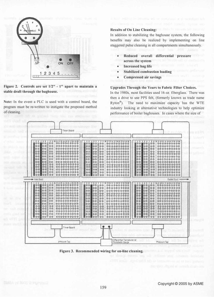
Read DP Across the Entire Fabric Filter
The first step to staggering the pulse sequence in all baghouse
compartments simultaneously is to set the cleaning controls to
read the differential pressure across the entire baghouse,
Pressure taps should be located in the ductwork prior to the
baghouse and after the baghouse before the fan, This will
provide a reading of the system pressure that the baghouse
imposes on the operation. When the pressure taps are
connected to a pressure transducer or Photohelic® gauge, the
cleaning around a set point on the gauge can be controlled so
that the pressure drop across the baghouse doesn't change
more than II2-inch w.c. and the fan will not realize major
system pressure changes. (Figure 2).
The pressure transducer should be wired to all the control
boards on all of the baghouse compartments. (Figure 3). When
the set point requires the collector to clean, one row in all the
compartments will pulse at the same time. Material will be
discharged into all the hoppers more evenly, and the resistance
across the baghouse will drop uniformly. Since the
differential change is distributed across the entire baghouse,
airflow will also be distributed uniformly .
If your operation requires changes 10 the combustion
process due to boiler load requirements, it is recommended
that a lower differential pressure setting be used to trigger the
cleaning cycles. The lower air volume will cause dust buildup
and suspension on the filter bags that doesn't increase the
differential pressure as dramatically as occurs with higher fan
volumes realized at a maximum combustion operation. When
the volumes are increased, the result is an immediate higher
differential pressure and problems with dust removal. If two
set points for triggering differential pressure cannot be
programmed, it is recommended to run the baghouse through
an entire cleaning cycle prior to operating at maximum
production levels. This will remove excess dust and allow for
maintaining more consistent differential pressures.
Copyright © 2005 by ASME
• aP ON
I I II
•
2345 .
Figure 2. Controls are set 112" - 1" apart to maintain a
stable draft through the baghouse.
Note: In the event a PLC is used with a control board, the
program must be re-written to instigate the proposed method
of cleaning.
�r1lJ"'� I I I
1 I
Results of On Line Cleaning:
In addition to stabilizing the baghouse system, the following
benefits may also be realized by implementing on line
staggered pulse cleaning in all compartments simultaneously.
• Reduced overall differential pressure
across the system
• Increased bag life
• Stabilized combustion loading
• Compressed air savings
Upgrades Through the Years to Fabric Filter Choices.
In the 1980s, most facilities used 16 oz. fiberglass. There was
then a drive to use PPS felt, (formerly known as trade name
Ryton�. The need to maximize capacity has the WTE
industry looking at alternative technologies to help optimize
performance of boiler baghouses. In cases where the size of
1 1 J 1
JL J -, It . . .. . -I " • ,.. U 11 go .* 1 .... IlI'q q .: • •• •• • •••• ""u." •• �U" . . . ·i�l·��·;;;;;;g;;� 00 00 oo· oooooocooo 00 00 00 00 0 000000' 0 00
00 00 00 0000000000 00 00 00 0'0000 0 0000 00 O�! 00 0000000000 00 00, 00 000000000-0 00 00 00 OCoGOOOOOO 00 00 0'0 00 00000000 00 OQ' 00 .000000000 0 00 (1) oQ OOQOOQOOO'O 00 00 00 00000000 00 0'0 00, 00 0000000000 00 00 00 00 00000000 00 00 00 OOOOQOQOQo 00 00 00 0000'000000 00 00 00 000 00000 000 00 00 OQ 0(100(100000 00: 00 00 '0000000000 o() 00, 00 OGOOO()()O()O 00 00 00 0000000000 00' 00 00 00 0 0000000 06 00 rOo O(lOOOOOGOO 00 00 0,0 0000 000000 00' 00 00 -0000000000 00 g�( g� 0 0 00000 0' 00 GO 00 00 ' 00000000 C) 0 00 00 0.0 00 00 000000 00 00 000 0 0000 00 00 00 00 00.000000 00 00 00 ,00 ()OOO 00 00 00 0'0. 00 oOOOOOOlHlO 00 ooj 00. '0000000000 (10 00 00 00000000100 00 o�l 00' 0000000000 00 00 00 00 0 0 00 00 00 00 00 00 000-000000 0 00 (10 00 0000000000 00 ooi 0(1 00 OOGO'OO 00 -'-
• 00' QQ 'QO'�OOO�oooo;;; • I t "8 'I , '" •• IH)1-I'MMttfJ8tt.,lI , •• of!: , " ,. 't. '.""311 �lfIl�"I"Jt',. 0.0 00 00 0000000000 00 00 00 000000-0:000
00 00 (10 oOQOoooooo 00 00 00 Q,O¢ooo�ooo 00 00 00 OOOOOOOOQO 00 00 00 00000000 00 00 00 0'0 0000000000 00 1)(1 00 000000000 0 00 00 00 00 000000. 00 00 00 CO 000'00,0'000'0 00 00 00 0000000000 00 00 00 OOOOOOQQOO 00 00 00 00000'00000. 00 00 00 0000000000 00: 0(1 Qo, QOOOOQooOQ 00 00 00 0000000000 00 00 00 0000000000 00 00, 00 0000000000 00 ,(1) 0'0 OOOO(H)OOOO 0 0 00 00 OOO'OOOQOOO 00 00 00 000000 00 0 0 00 00 00 00 00000000 00 '00 00 OOoOOoQO()Q 0-1). 00 00 ,00 00000000 00 00 00. 0000'0000.00 00 00 00 0000000000 00 011 00 0000000000 00 00 '00 0000000000 00 o�� 00 0000000000 00 00 00 -0000000000 00 co 00 000000 0 00 0 00 0.0 00 -0000000000 OQ 00 00 00 0 00/:) 00 (1.0 0 0 00 00 0000000000 '00 00 00 00 00 00 00 00 00: 00 '00 0000(1 Q 0000' 00 00 0'0 0000'000000 00 O QJ 0<1 OQI)OQoaooo
_ . , . .. .. ... _ ."
, I It 11
-j : I I j'IDorGo;lnl f I I I
: J l \ J [ O'rwlur. r.p J I :Citl'!tI(itlNil r�'i$lw:�r t)r
p'Mro�G;n.l'J �!e1lQ
Figure 3. Recommended wiring for on-line cleaning.
Copyright © 2005 by ASME 159

the baghouse is a restriction to the amount of airflow that it
can accept, pleated filters have been used to dramatically
increase the amount of cloth area available for filtration. Until
recently, pleated filters were available only in fibers
withstanding temperatures below 2750 F ( 1350 C). However,
in the last several years, pleated filters have become available
in aramid, PPS, and even fiberglass media. These
developments expand the options for producers restricted in
production by the size of the primary dust collection system.
Pleated filter elements provide a simple retrofit for
upgrading existing dust collectors and improving problematic
systems. These elements are one-piece units that are a direct
replacement for traditional filter bags and cages in pulse-jet
units. The media resists surface penetration of particulate,
dramatically increasing efficiencies while operating at
significantly lower differential pressures than felted or woven
materials. The media is pleated and molded into a filter
element, increasing filtration surface area over filter bags by
up to 300%, depending on existing filter bag sizes. Though
shorter in length, filter elements actually increase the available
filtration area on a hole for hole basis.
PFEs as a Problem Solver
Pleated filter elements can also help with other problems
common to pulse-jet cleaning baghouses including bottom bag
abrasion, inlet abrasion, high hopper levels, and heavy grain
loading to the filter elements.
Figure 4. Bottom bag abrasion
Bottom bag abrasion (Figure 4) is very common in pulse-jet
baghouses. It typically occurs opposite the inlet and around
the periphery of the baghouse. As the flue gas enters a
module, typical baffling redirects the gas stream down into the
hopper. Since the hopper is a converging cone and the cross
sectional diameter gets smaller, the gas stream speeds up
causing dust to be re-entrained to the filter bags. Since PFEs
are much shorter in length, they can
160
III most cases completely eliminate bottom bag abrasion
(Figure 5).
Oro, OUlZonl
� <t <t r:J.) �J..J
�
Figure 5. Shorter ThermoPleat elements eliminate
abrasion problems and are less susceptible to high grain
loading.
Meeting new emissions requirements with the addition of
controls such as spray dryer absorbers, carbon injection, and
dry scrubbers can add grain loading to the filters. The
additional grain loading in many cases means the fabric filter
will operate at a much higher differential pressure than its
design allows. It's a common occurrence to find facilities
today that were designed to operate at much lower airflows in
the past that are now needing upgrades to meet today's
increased production. Pleated filter elements can double or
triple the available cloth area to carry the added airflow. Also,
because they're shorter in length there is a much larger drop
out zone underneath them where the flue gas stream can
expand and slow down allowing some of the heavier
particulate to drop out of the gas stream before ever reaching
the PFEs. In many cases a conversion from conventional bags
and cages to pleated filter elements means an additional drop
out zone for particulate entering a baghouse anywhere from 4
to 10 feet.
Additionally the shorter length of PFEs will be an
advantage when high hopper levels are experienced. From
time-to-time all plants experience plugged hoppers that can
literally vaporize the long conventional filters that hang close
to the hopper area of the baghouse. By installing PFEs the
larger drop out zone will add protection to the filters when
high hopper levels are experienced.
Copyright © 2005 by ASME

ThermoPleat® - for temps up to 450°F
Conclusion
In summary, the future will bring more opportunities for the
WTE industry to become more profitable. The ideas provided
in this discussion provide the ability to increase profitability
by impacting the back end equipment. Advances that may not
have been economically feasible in the past can now be.
optimistically considered.
All trademarks referenced herein are property of their respective owners.
Copyright © 2005 by ASME 161


![WELCOME [fikhaglobalteknik.com] · • Pulse Jet Baghouse • Reverse Air Baghouse Dust Collectors • Shaker baghouse dust collector • Automation System • PLC (programable Logic](https://img.pdfslide.us/doc/110x75/600d3569c9481d2aff589460/welcome-a-pulse-jet-baghouse-a-reverse-air-baghouse-dust-collectors-a.jpg)