Embed Size (px)
Citation preview
27TH INTERNATIONAL CONGRESS OF THE AERONAUTICAL SCIENCES
PULSE DETONATION AS AN OPTION FOR FUTURE
INNOVATIVE GAS TURBINE COMBUSTION TECHNOLOGIES: A CONCEPT ASSESSMENT
Fabrice Giuliani*, Andreas Lang*, Mohammad Irannezhad**, Anders Lundbladh***
*Combustion Department, Institute for Thermal Turbomachinery and Machine Dynamics,
Graz University of Technology, 8010 Graz, Austria
**Department of Applied Mechanics, Chalmers University of Technology 412 96 Göteborg, Sweden
***Performance & Control Systems, Volvo Aero Corporation,
Dept 7164AL, 461 81 Trollhättan, Sweden
Keywords: pulse detonation, gas turbine performance, hybrid engine, CFD
Abstract
A study on innovative combustion system for future aeroengine core concepts is done in the frame of the NEWAC project (EU FP6, AIP5-CT-2006-030876). A part of the high pressure core is replaced by a pulse detonation combustor. The ambition is to achieve a technical leap in TSFC reduction, or alternatively a lighter engine. In order to provide technical assessments on both the feasibility and performance of such a concept, specific tools were developed at TU Graz, Austria and Chalmers University, Sweden. The study emphasises the impact of flow intermittency on the direct environment of the pulse detonation combustor, and on the performance of a hybrid turbofan. A literature survey establishes the state of the art on pulse detonation technologies. Numerical tools for CFD calculation and performance analysis are presented. A concept assessment with a TSFC reduction by 5% in comparison to a conventional cycle is derived.
1 General Introduction
The need for more efficient and environment friendly engines is tending towards new methods of combustion. Although new injections systems currently in development, like LPP (Lean Premixed Prevaporised), RQL (Rich burn Quick quench Lean burn) and LDI (Lean Direct Injection), are promising a reduction in pollutant emission there is also the trend to look for innovative combustion methods to lower in addition fuel consumption. One premising way to reduce thrust specific fuel consumption (TSFC) is to use pulse detonation [6].
A study on innovative combustion system for future aeroengine core concepts is done in the frame of the NEWAC project. A part of the high pressure core of a conventional aeroengine is replaced by a pulse detonation combustor. A medium-range two-spool turbofan is taken as a baseline for a back-to-back comparison.
Pulse detonation (PD) is attractive because of its potential for higher thermal efficiency
1
GIULIANI, LANG
than conventional combustion (deflagration at constant pressure).
However, involving detonation implies an increase in technical complexity in comparison with conventional combustors, and the current TRL on pulse detonation is still low. In order to provide technical assessments on both the feasibility and the performance of such a concept, the work was split in three main steps and covered by TU Graz, Austria, in collaboration with Chalmers University, Sweden. Guidance was provided by Volvo Aero, Sweden, for this specific task, in the frame of a more general study on innovative core under the supervision of MTU, Germany.
A preliminary study based on an extensive literature survey established stationary pulse detonation tube combustors as a promising technology compatible with a standard turbofan engine architecture with innovative core concepts for gas turbines.
The second step covered the aspects of flow intermittency. For this, the G2D code of Chalmers was used, with an effort to compute realistically the pulse detonation cycle in terms of operating conditions, fuel, and flexibility on the ignition sequence from one detonator to the next. Two aspects were analysed: the peak values of thermodynamic variables as a function of the ignition sequence, and the degradation of the turbine efficiency due to the flow intermittency.
In a third step, a study on hybrid engine performance was done. Tools to compute the thermodynamics of a hybrid engine were developed and a back-to-back comparison with a conventional turbofan was performed. Two paths were followed: towards a lighter engine at the same fuel burn, or towards lower fuel burn. Rough assessments were done in terms of pollutant emissions and engine sizing.
The article reports on the three steps, and ends with recommendations towards demonstration activities.
2 Preliminary design study
2.1 Pulse detonation Pulse detonation is based on a batch cycle
consisting in filling a cavity with fresh reactants (usually a tube with a backflow-valve inlet and an opened outlet), let them detonate with help of a strong energy spark and near stoichiometric mixture conditions, take benefit of the brutal gas ejection and subsequent pressure drop in the tube to refill with buffer air for cooling followed by reactants, starting the next cycle.
Compared to conventional combustion at constant pressure, detonation offers a higher predicted thermal efficiency. After a period called deflagration-to-detonation transition (DDT) following the ignition, the fresh reactants are first compressed by a shock wave and therefore heated up, after that the Rayleigh heat addition takes place at elevated pressure, and the subsequent burnt gas release maintain the detonation process by thrusting the shock wave forward. The process of heat addition at elevated pressure is responsible for a better thermal efficiency. Provided the flow is throttled, the process is pressure gain, which means the cycle-averaged pressure is more elevated at the outlet than at the inlet condition.
Therefore it is intended to use a set of pulse detonation tubes, derived from pulse detonation engines usually used as thrusters, as replacement for the conventional combustor within a turbofan engine. As a potential substitute to the Brayton cycle, this so-called PD-based hybrid gas turbine cycle can make benefit of the better thermal efficiency to reduce its fuel burn, and/or make use of the pressure gain to reduce the compressor size hence getting a lighter frame.
However, the PD process is a technology with low TRL, currently at the demonstrator level. Many engineering problems are related to the precise timing of the process, to its fine-tuning as a function of the operation, and to the limited endurance of the parts facing intermittent peaks of elevated pressure and temperature. The fuel is also a key point. Air-hydrogen mixtures are mostly used in basic research activities. But using conventional fuels
2
PULSE DETONATION AS AN OPTION FOR INNOVATIVE GAS TURBINE COMBUSTION TECHNOLOGIES
such as kerosene is challenging given the short injection timing and the need to evaporate and mix as quickly and as regularly as possible. The effects of the flow intermittency in a continuous process are not well-known. The facts that the reactant mixture is near stoichiometry to ensure detonation and that the peak temperatures are well above 2000K enhance the production of thermal NOx. Furthermore, the fact that the process is pressure gain works against a conventional cooling method using bleed air from the HPC. Further compression of cooling air towards the PDC casing and the HPT is therefore required. The complexity of cycle automation and the noise are also two more problems to be taken into account.
2.2 Literature survey, statistics The processed literature during the design
phase of this study covers about 150 articles issued from journal publications and international conferences, mostly over the 20 last years. It can be observed in Fig. 1 that the leader in PD technologies is Northern America, especially concerning applied research and demonstration. After that, European countries compete at a much lower level of investment and capacities with Russia and south-east countries. Based on a fair comparison in terms of publication numbers and quality, there is clearly a need to catch-up at European level with this technology.
Fig. 1: Articles on innovative combustion as a function of the country of origin of the host research institution.
2.3 Hybrid engine concept In this study, attention is paid to combine
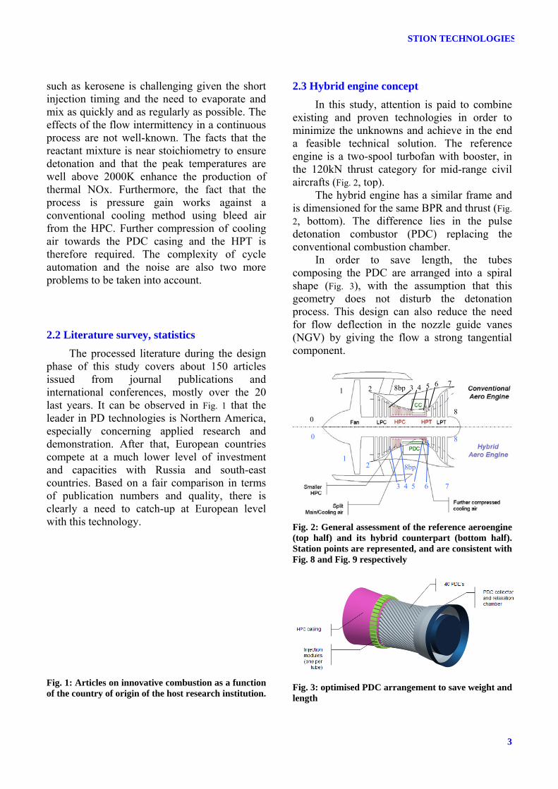
existing and proven technologies in order to minimize the unknowns and achieve in the end a feasible technical solution. The reference engine is a two-spool turbofan with booster, in the 120kN thrust category for mid-range civil aircrafts (Fig. 2, top).
The hybrid engine has a similar frame and is dimensioned for the same BPR and thrust (Fig. 2, bottom). The difference lies in the pulse detonation combustor (PDC) replacing the conventional combustion chamber.
In order to save length, the tubes composing the PDC are arranged into a spiral shape (Fig. 3), with the assumption that this geometry does not disturb the detonation process. This design can also reduce the need for flow deflection in the nozzle guide vanes (NGV) by giving the flow a strong tangential component.
0
0
1 2 3 4 5 6 7
8
8bp
1 2
3 4 5 6 7
8
8bp
Fig. 2: General assessment of the reference aeroengine (top half) and its hybrid counterpart (bottom half). Station points are represented, and are consistent with Fig. 8 and Fig. 9 respectively
Fig. 3: optimised PDC arrangement to save weight and length
3
GIULIANI, LANG
3 CFD study on the effect of the flow intermittency on the turbine entry conditions
3.1 The G2D software The code G2D developed at Chalmers
University is described more into detail for PDE simulation applications in [8]. It is cell centred finite surface, with URANS solver. Time-marching is performed using a second-order Runge-Kutta technique. A third-order upwind scheme approximates the convective flux while the diffusive flux is approximated with a second-order scheme.
The gases are assumed to be calorifically perfect so that the internal energy and enthalpy are function of the temperature only. The performance combustion tables have been generated with the CEA code (chemical equilibrium [9]). The species are introduced to the solver as their heat of formation, specific heat at constant volume and their gas constant. These are issued from linear interpolation of available data from thermodynamic tables. The combustion model is based on a single reaction model and predicts the reactions rates according to a simple Arrhenius expression with a threshold temperature below which all the reactions are neglected. The ignition is introduced by a point source in the tube, under the form of a constant energy addition. This source is effective for some time steps and its strength is set to rise the temperature above the threshold of the combustion model.
The outlet is set to an open boundary condition, at constant pressure with a pressure drop proportional to the velocity to avoid unstable large intakes in severe transients. This choice of boundary condition also introduces partial absorption of the waves at the outlet.
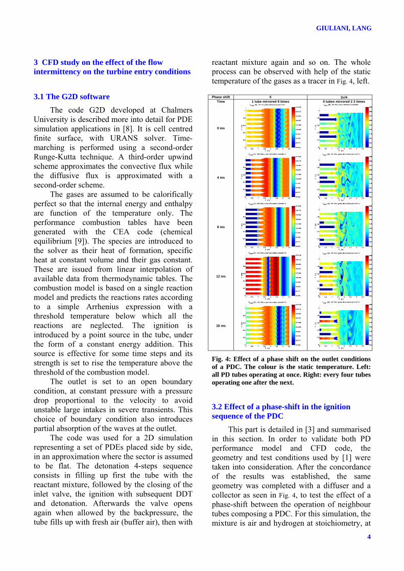
The code was used for a 2D simulation representing a set of PDEs placed side by side, in an approximation where the sector is assumed to be flat. The detonation 4-steps sequence consists in filling up first the tube with the reactant mixture, followed by the closing of the inlet valve, the ignition with subsequent DDT and detonation. Afterwards the valve opens again when allowed by the backpressure, the tube fills up with fresh air (buffer air), then with
reactant mixture again and so on. The whole process can be observed with help of the static temperature of the gases as a tracer in Fig. 4, left.
Phase shift 0 2π/4
Time 1 tube mirrored 9 times 4 tubes mirrored 2 2 times
0 ms
4 ms
8 ms
12 ms
16 ms
Fig. 4: Effect of a phase shift on the outlet conditions of a PDC. The colour is the static temperature. Left: all PD tubes operating at once. Right: every four tubes operating one after the next.
3.2 Effect of a phase-shift in the ignition sequence of the PDC
This part is detailed in [3] and summarised in this section. In order to validate both PD performance model and CFD code, the geometry and test conditions used by [1] were taken into consideration. After the concordance of the results was established, the same geometry was completed with a diffuser and a collector as seen in Fig. 4, to test the effect of a phase-shift between the operation of neighbour tubes composing a PDC. For this simulation, the mixture is air and hydrogen at stoichiometry, at
4
PULSE DETONATION AS AN OPTION FOR INNOVATIVE GAS TURBINE COMBUSTION TECHNOLOGIES
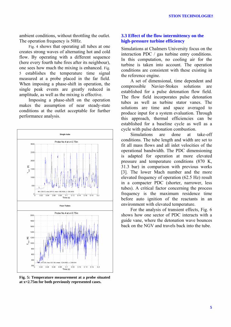
ambient conditions, without throttling the outlet. The operation frequency is 50Hz.
Fig. 4 shows that operating all tubes at one creates strong waves of alternating hot and cold flow. By operating with a different sequence (here every fourth tube fires after its neighbour), one sees how much the mixing is enhanced. Fig. 5 establishes the temperature time signal measured at a probe placed in the far field. When imposing a phase-shift in operation, the single peak events are greatly reduced in amplitude, as well as the mixing is effective.
Imposing a phase-shift on the operation makes the assumption of near steady-state conditions at the outlet acceptable for further performance analysis.
Single tube
Four-Tubes
Fig. 5: Temperature measurement at a probe situated at x=2.75m for both previously represented cases.
3.3 Effect of the flow intermittency on the high-pressure turbine efficiency
Simulations at Chalmers University focus on the interaction PDC / gas turbine entry conditions. In this computation, no cooling air for the turbine is taken into account. The operation conditions are consistent with these existing in the reference engine.
A set of dimensional, time dependent and compressible Navier-Stokes solutions are established for a pulse detonation flow field. The flow field incorporates pulse detonation tubes as well as turbine stator vanes. The solutions are time and space averaged to produce input for a system evaluation. Through this approach, thermal efficiencies can be established for a baseline cycle as well as a cycle with pulse detonation combustion.
Simulations are done at take-off conditions. The tube length and width are set to fit all mass flows and all inlet velocities of the operational bandwidth. The PDC dimensioning is adapted for operation at more elevated pressure and temperature conditions (870 K, 31.3 bar) in comparison with previous works [3]. The lower Mach number and the more elevated frequency of operation (62.5 Hz) result in a compacter PDC (shorter, narrower, less tubes). A critical factor concerning the process frequency is the maximum residence time before auto ignition of the reactants in an environment with elevated temperature.
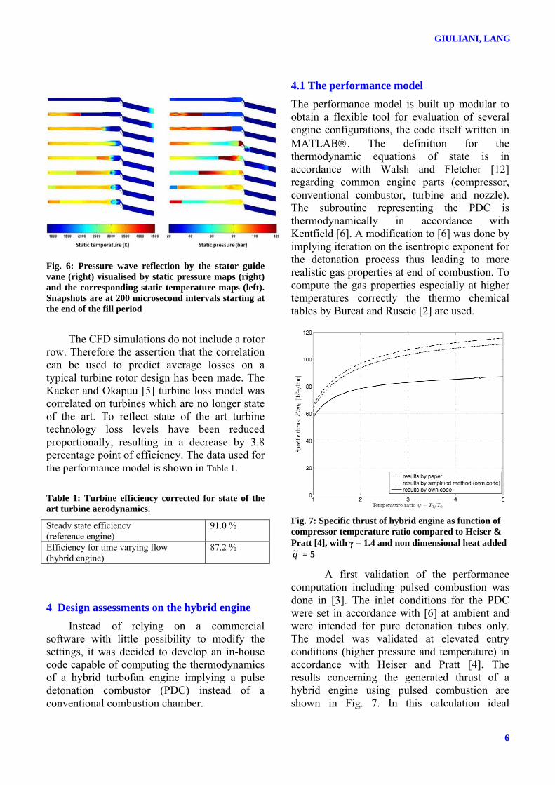
For the analysis of transient effects, Fig. 6 shows how one sector of PDC interacts with a guide vane, where the detonation wave bounces back on the NGV and travels back into the tube.
5
GIULIANI, LANG
Fig. 6: Pressure wave reflection by the stator guide vane (right) visualised by static pressure maps (right) and the corresponding static temperature maps (left). Snapshots are at 200 microsecond intervals starting at the end of the fill period
The CFD simulations do not include a rotor
row. Therefore the assertion that the correlation can be used to predict average losses on a typical turbine rotor design has been made. The Kacker and Okapuu [5] turbine loss model was correlated on turbines which are no longer state of the art. To reflect state of the art turbine technology loss levels have been reduced proportionally, resulting in a decrease by 3.8 percentage point of efficiency. The data used for the performance model is shown in Table 1.
Table 1: Turbine efficiency corrected for state of the art turbine aerodynamics.
Steady state efficiency (reference engine)
91.0 %
Efficiency for time varying flow (hybrid engine)
87.2 %
4 Design assessments on the hybrid engine Instead of relying on a commercial
software with little possibility to modify the settings, it was decided to develop an in-house code capable of computing the thermodynamics of a hybrid turbofan engine implying a pulse detonation combustor (PDC) instead of a conventional combustion chamber.
4.1 The performance model The performance model is built up modular to obtain a flexible tool for evaluation of several engine configurations, the code itself written in MATLAB®. The definition for the thermodynamic equations of state is in accordance with Walsh and Fletcher [12] regarding common engine parts (compressor, conventional combustor, turbine and nozzle). The subroutine representing the PDC is thermodynamically in accordance with Kentfield [6]. A modification to [6] was done by implying iteration on the isentropic exponent for the detonation process thus leading to more realistic gas properties at end of combustion. To compute the gas properties especially at higher temperatures correctly the thermo chemical tables by Burcat and Ruscic [2] are used.
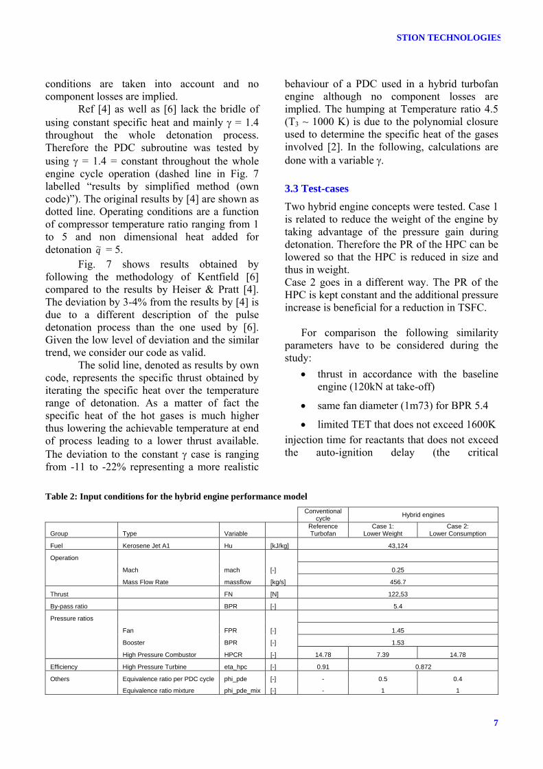
Fig. 7: Specific thrust of hybrid engine as function of compressor temperature ratio compared to Heiser & Pratt [4], with γ = 1.4 and non dimensional heat added q~ = 5
A first validation of the performance computation including pulsed combustion was done in [3]. The inlet conditions for the PDC were set in accordance with [6] at ambient and were intended for pure detonation tubes only. The model was validated at elevated entry conditions (higher pressure and temperature) in accordance with Heiser and Pratt [4]. The results concerning the generated thrust of a hybrid engine using pulsed combustion are shown in Fig. 7. In this calculation ideal
6
PULSE DETONATION AS AN OPTION FOR INNOVATIVE GAS TURBINE COMBUSTION TECHNOLOGIES
conditions are taken into account and no component losses are implied.
Ref [4] as well as [6] lack the bridle of using constant specific heat and mainly γ = 1.4 throughout the whole detonation process. Therefore the PDC subroutine was tested by using γ = 1.4 = constant throughout the whole engine cycle operation (dashed line in Fig. 7 labelled “results by simplified method (own code)”). The original results by [4] are shown as dotted line. Operating conditions are a function of compressor temperature ratio ranging from 1 to 5 and non dimensional heat added for detonation q~ = 5.
Fig. 7 shows results obtained by following the methodology of Kentfield [6] compared to the results by Heiser & Pratt [4]. The deviation by 3-4% from the results by [4] is due to a different description of the pulse detonation process than the one used by [6]. Given the low level of deviation and the similar trend, we consider our code as valid.
The solid line, denoted as results by own code, represents the specific thrust obtained by iterating the specific heat over the temperature range of detonation. As a matter of fact the specific heat of the hot gases is much higher thus lowering the achievable temperature at end of process leading to a lower thrust available. The deviation to the constant γ case is ranging from -11 to -22% representing a more realistic
behaviour of a PDC used in a hybrid turbofan engine although no component losses are implied. The humping at Temperature ratio 4.5 (T3 ~ 1000 K) is due to the polynomial closure used to determine the specific heat of the gases involved [2]. In the following, calculations are done with a variable γ.
3.3 Test-cases Two hybrid engine concepts were tested. Case 1 is related to reduce the weight of the engine by taking advantage of the pressure gain during detonation. Therefore the PR of the HPC can be lowered so that the HPC is reduced in size and thus in weight. Case 2 goes in a different way. The PR of the HPC is kept constant and the additional pressure increase is beneficial for a reduction in TSFC.
For comparison the following similarity parameters have to be considered during the study:
• thrust in accordance with the baseline engine (120kN at take-off)
• same fan diameter (1m73) for BPR 5.4
• limited TET that does not exceed 1600K injection time for reactants that does not exceed the auto-ignition delay (the critical
Table 2: Input conditions for the hybrid engine performance model
Conventional
cycle Hybrid engines
Group Type Variable Reference Turbofan
Case 1: Lower Weight
Case 2: Lower Consumption
Fuel Kerosene Jet A1 Hu [kJ/kg] 43,124
Operation
Mach mach [-] 0.25
Mass Flow Rate massflow [kg/s] 456.7
Thrust FN [N] 122,53
By-pass ratio BPR [-] 5.4
Pressure ratios
Fan FPR [-] 1.45
Booster BPR [-] 1.53
High Pressure Combustor HPCR [-] 14.78 7.39 14.78
Efficiency High Pressure Turbine eta_hpc [-] 0.91 0.872
Others Equivalence ratio per PDC cycle phi_pde [-] - 0.5 0.4
Equivalence ratio mixture phi_pde_mix [-] - 1 1
7
8TH INTERNATIONAL SYMPOSIUM ON FLOW VISUALIZATION (1998)
self-ignition delay was computed after Spadaccini and TeVelde [11])
• limited resulting pressure 60 bar in the PDC collector
• LPT entry temperature below 1350K, to avoid the necessity to cool down the LPT
• HPT efficiency was decreased compared to the reference engine based on results of CFD-calculations by Chalmers University [8]. The original HPT efficiency was reduced by 3.8 percentage points from 91% to 87.2%.
Further input conditions for the hybrid engine performance model are given in Table 2.
For the test cases neither pressure losses due to the necessary valves at the inlet of the detonation tubes are foreseen, nor are effects regarding flow intermittency at the HPC outlet or on the LPT taken into account.
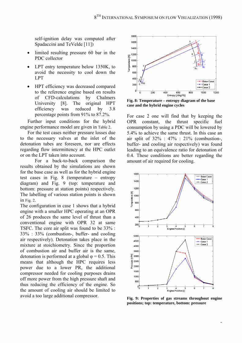
For a back-to-back comparison the results obtained by the simulations are shown for the base case as well as for the hybrid engine test cases in Fig. 8 (temperature – entropy diagram) and Fig. 9 (top: temperature and bottom: pressure at station points) respectively. The labelling of various station points is shown in Fig. 2. The configuration in case 1 shows that a hybrid engine with a smaller HPC operating at an OPR of 26 produces the same level of thrust than a conventional engine with OPR 32 at same TSFC. The core air split was found to be 33% : 33% : 33% (combustion-, buffer- and cooling air respectively). Detonation takes place in the mixture at stoichiometry. Since the proportion of combustion air and buffer air is the same, detonation is performed at a global φ = 0.5. This means that although the HPC requires less power due to a lower PR, the additional compressor needed for cooling purposes drains off more power from the high pressure shaft and thus reducing the efficiency of the engine. So the amount of cooling air should be limited to avoid a too large additional compressor.
Fig. 8: Temperature – entropy diagram of the base case and the hybrid engine cycles For case 2 one will find that by keeping the OPR constant, the thrust specific fuel consumption by using a PDC will be lowered by 5.4% to achieve the same thrust. In this case an air split of 32% : 47% : 21% (combustion-, buffer- and cooling air respectively) was found leading to an equivalence ratio for detonation of 0.4. These conditions are better regarding the amount of air required for cooling.
Fig. 9: Properties of gas streams throughout engine positions; top: temperature, bottom: pressure
-
PAPER TITLE
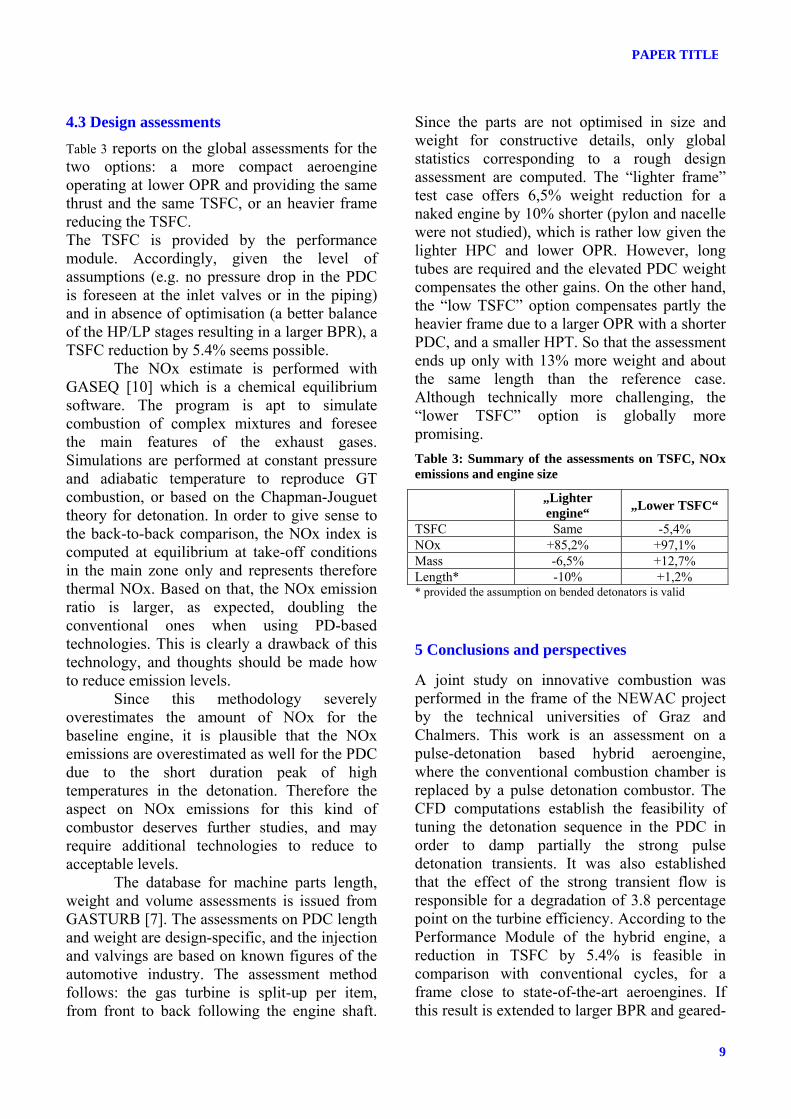
4.3 Design assessments Table 3 reports on the global assessments for the two options: a more compact aeroengine operating at lower OPR and providing the same thrust and the same TSFC, or an heavier frame reducing the TSFC. The TSFC is provided by the performance module. Accordingly, given the level of assumptions (e.g. no pressure drop in the PDC is foreseen at the inlet valves or in the piping) and in absence of optimisation (a better balance of the HP/LP stages resulting in a larger BPR), a TSFC reduction by 5.4% seems possible.
The NOx estimate is performed with GASEQ [10] which is a chemical equilibrium software. The program is apt to simulate combustion of complex mixtures and foresee the main features of the exhaust gases. Simulations are performed at constant pressure and adiabatic temperature to reproduce GT combustion, or based on the Chapman-Jouguet theory for detonation. In order to give sense to the back-to-back comparison, the NOx index is computed at equilibrium at take-off conditions in the main zone only and represents therefore thermal NOx. Based on that, the NOx emission ratio is larger, as expected, doubling the conventional ones when using PD-based technologies. This is clearly a drawback of this technology, and thoughts should be made how to reduce emission levels.
Since this methodology severely overestimates the amount of NOx for the baseline engine, it is plausible that the NOx emissions are overestimated as well for the PDC due to the short duration peak of high temperatures in the detonation. Therefore the aspect on NOx emissions for this kind of combustor deserves further studies, and may require additional technologies to reduce to acceptable levels.
The database for machine parts length, weight and volume assessments is issued from GASTURB [7]. The assessments on PDC length and weight are design-specific, and the injection and valvings are based on known figures of the automotive industry. The assessment method follows: the gas turbine is split-up per item, from front to back following the engine shaft.
Since the parts are not optimised in size and weight for constructive details, only global statistics corresponding to a rough design assessment are computed. The “lighter frame” test case offers 6,5% weight reduction for a naked engine by 10% shorter (pylon and nacelle were not studied), which is rather low given the lighter HPC and lower OPR. However, long tubes are required and the elevated PDC weight compensates the other gains. On the other hand, the “low TSFC” option compensates partly the heavier frame due to a larger OPR with a shorter PDC, and a smaller HPT. So that the assessment ends up only with 13% more weight and about the same length than the reference case. Although technically more challenging, the “lower TSFC” option is globally more promising. Table 3: Summary of the assessments on TSFC, NOx emissions and engine size
„Lighter engine“ „Lower TSFC“
TSFC Same -5,4% NOx +85,2% +97,1% Mass -6,5% +12,7% Length* -10% +1,2% * provided the assumption on bended detonators is valid 5 Conclusions and perspectives
A joint study on innovative combustion was performed in the frame of the NEWAC project by the technical universities of Graz and Chalmers. This work is an assessment on a pulse-detonation based hybrid aeroengine, where the conventional combustion chamber is replaced by a pulse detonation combustor. The CFD computations establish the feasibility of tuning the detonation sequence in the PDC in order to damp partially the strong pulse detonation transients. It was also established that the effect of the strong transient flow is responsible for a degradation of 3.8 percentage point on the turbine efficiency. According to the Performance Module of the hybrid engine, a reduction in TSFC by 5.4% is feasible in comparison with conventional cycles, for a frame close to state-of-the-art aeroengines. If this result is extended to larger BPR and geared-
9
GIULIANI, LANG
turbofans, PDC is a candidate to achieve a technical leap in terms of TSFC reduction. The PDC is also compatible to some extent with existing aeroengine architectures. A dimensioning exercise established that based on the same thrust, weight and length reductions up to 6% and 10 % respectively are feasible. Due to the extreme temperatures of the PDC cycle, NOx emissions may be doubled.
Given these figures, this technology is very promising in terms of fuel burn reduction. The question on NOx needs further research, since emissions must be reduced. There is obviously a need to catch-up with PD-based technologies at European level. The erection of experimental facilities towards operation at elevated pressure is the next logical step of this work.
Acknowledgements This study realised by TU Graz and
Chalmers University was supported by the European Commission as part of the Integrated Project ”New Aeroengine Core Concepts” (NEWAC, AIP5-CT-2006-030876). The EC, the Project Co-ordination, as well as our partners from MTU Aeroengines and Volvo Aero are gratefully acknowledged.
References [1] Aarnio, M.J., Hinkey, J.B. and Bussing, T.R.A.
“Multiple cycle detonation experiments during the development of a pulse detonation engine”. 32d AIAA / ASME / SAE / ASEE Joint Propulsion Conference. July 1-3, 1996 / Lake Buena Vista, FL. AIAA 96-3263
[2] Burcat A., Ruscic B.; “Third Millennium Ideal Gas and Condensed Phase Thermochemical Database for Combustion with Updates from Active Thermochemical Tables”, Technion/Argonne National Laboratory. Sep, 2005 - technion.ac.il
[3] Giuliani, F., Lang, A., Irannezhad, M., and Grönstedt, T. (2009). Effect of a controlled phase-shift on the outlet conditions of a set of pulse detonators. In 19th
ISABE Conference, Montreal, Canada. ISABE-2009-1315.
[4] Heiser, W.H. and Pratt, D.T. “Thermodynamic Cycle Analysis of Pulse Detonation Engines”, Journal of Propulsion and Power, Vol. 18, No. 1, January-February 2002
[5] Kacker, S.C. and Okapuu, U. “A Mean Line Prediction Method for Axial Flow Turbine Efficiency”, ASME J. Eng. for Power, 104 (1982), pp 111-119.
[6] Kentfield, J. A. C., “Thermodynamics of Airbreathing Pulse-Detonation Engines”, Journal of Propulsion and Power, Vol. 18, No. 6, November-December 2002
[7] Kurzke, J. GasTurb 11. “Design and off-design performance of gas turbines”. Operation manual, 2007.
[8] Liberman, M. A., Sivashinsky, G. I., Valiev, D. M. and Eriksson, L-E. “Numerical simulation of deflagration-to-detonation transition: the role of hydrodynamic instability”, The 16th International Symposium on Transport Phenomena (ISTP-16), Prague, 2005
[9] McBride, B. J. and Gordon, S., "Computer Program for Calculation of Complex Chemical Equilibrium Compositions and Applications II. User's Manual and Program Description", NASA RP-1311-P2, June 1996.
[10] Morley C.: GASEQ – Chemical equilibria in perfect gases, Version 0.79, http://www.gaseq.co.uk, March 2008
[11] Spadaccini, L.J. and TeVelde, J.A. Autoignition characteristics of aircraft-type fuels. Combustion and Flame, 46:283–300, 1982.
[12] Walsh, P.P. and Fletcher, P., “Gas Turbine Performance”, 2nd Edition, Blackwell Publishing
Copyright Statement The authors confirm that they, and/or their company or organization, hold copyright on all of the original material included in this paper. The authors also confirm that they have obtained permission, from the copyright holder of any third party material included in this paper, to publish it as part of their paper. The authors confirm that they give permission, or have obtained permission from the copyright holder of this paper, for the publication and distribution of this paper as part of the ICAS2010 proceedings or as individual off-prints from the proceedings.
10