Embed Size (px)
Citation preview

This document contains data proprietary to PUI Audio Inc. Any use or reproduction, in any form, without prior written permission of PUI Audio Inc. is prohibited.
©2018, PUI Audio Inc.
PUI Audio, Inc. A Projects Unlimited Company, 3541 Stop Eight Road, Dayton, OH 45414 Tel: (937) 415-5901 Fax: (937) 415-5925
User’s Guide and Specifications AMP2X15 Audio Amplifier Board PUI Audio’s AMP2X15 audio amplifier board features a Texas Instruments’ TPA3110D2 Class D amplifier circuit for maximum signal fidelity; delivering 6 Watts per channel of low-distortion power (0.1% THD+N) into 4Ω loads; 15 watts per channel into 8Ω loads (10% THD+N with 16 VDC supply). The AMP2X15 is purpose-built to aid and assist engineers in prototyping audio solutions for a multitude of applications, and offers single-ended and differential inputs with stereo BTL or mono PBTL outputs. Features:
• Small form factor—76.2mm x 50.8mm x 20mm (L x W x H) • Wide +9.5V to +20V DC input range (power supply not included) • Three different input connections—stereo 3.5mm jack, terminal blocks, six-circuit
Molex® SL™ 70543 connector • Audiophile-grade sound quality • Single-ended and differential inputs; stereo or mono output • Built-in over-current and over-temperature protection
Note: Please read this manual carefully before using this product. To keep the product in the best working condition,
please operate it according to the relevant steps. Warranty is void if this product is misused.
Please read this manual carefully before you use the product. A DC power supply with 9.5V to 20V output (and a
minimum of 2A of current capacity) is recommended to be used to power this product.
Safety Precautions:
1. In order to achieve the best sound quality, please use a stable power supply. A bad or unstable power supply
will reduce the sound quality or even damage the amplifier board.
2. Avoid metal objects coming into contact with this product. Protect the solder joints on the bottom of the PCB
when mounting this product.
3. Do not connect a pre-amplifier to the input of this product. Enough gain is provided to allow the amplifier to
develop maximum power output. Doing so may damage the amplifier. Ensure the audio input signal is at a
minimum when powering on the amplifier, to protect the amplifier and connected speakers.
4. Never expose this product to rain or extremely humid (>95% relative humidity) environments to prevent fire
or electric shock.

This document contains data proprietary to PUI Audio Inc. Any use or reproduction, in any form, without prior written permission of PUI Audio Inc. is prohibited.
©2018, PUI Audio Inc.
PUI Audio, Inc. A Projects Unlimited Company, 3541 Stop Eight Road, Dayton, OH 45414 Tel: (937) 415-5901 Fax: (937) 415-5925
Specifications The following table lists all typical data of the PUI Audio Amplifier Board. For full specifications, please refer to the Texas Instruments’ TPA3110D2 technical specifications. All parameters below are tested @ TA=25°C, 12 VDC input voltage (unless otherwise stated), 1 kHz sine wave input, with gain set to 26 dB.
Parameter Condition Min. Typ. Max.
Supply Voltage (Vcc) - 9.5V 12V 20V
Input Sensitivity 8Ω, 8W, 1kHz - 0.428V -
Signal-to-Noise Ratio THD+ N < 1%, f = 1
kHz, 6W, 8Ω - 94 dB -
Total Harmonic Distortion +
Noise
Vcc = 12 V, f = 1
kHz, Po = 5W
(half-power)
- 0.06% -
RL = 8 Ω, f = 1 kHz,
Po = 10W - 10% -
Efficiency
Vcc= 12 VDC,
RL=8Ω, Pout= 8W - 86.4% -
Vcc=12 VDC,
RL=8Ω, Po= 10W 89% -
Input Impedance - - 30 kOhm -
Gain - 26 dB
Output Power (Po)
(per channel)
THD+N=10%, f = 1
kHz, Vcc=16 VDC,
RL=8Ω
- 15W -
THD+N = 0.1%, f = 1
kHz; Vcc = 12 VDC,
RL=4Ω, 0.7V input
signal
- 6W -
Frequency Response - - 20-20,000 Hz
(±3dB) -
Quiescent Current SD = 2V, no load,
Vcc = 12 VDC - 20mA 35mA
Minimum Resistive Load (RL) - 3.2 ohm 4 ohm -
Operating Temperature - -40 20 65
Storage Temperature - -60 20 105
Thermal Shutdown - - 150 -
Setup

This document contains data proprietary to PUI Audio Inc. Any use or reproduction, in any form, without prior written permission of PUI Audio Inc. is prohibited.
©2018, PUI Audio Inc.
PUI Audio, Inc. A Projects Unlimited Company, 3541 Stop Eight Road, Dayton, OH 45414 Tel: (937) 415-5901 Fax: (937) 415-5925
Output Mode and Input Mode Switching
This audio amplifier board supports switching between stereo (BTL) and mono (PBTL) modes, as well as single-ended (V0-p) and differential (Vp-p) inputs. Two switches control the operation of these modes on the amplifier board.
Stereo (BTL) and mono (PBTL) modes are controlled by the position of SW1 (A or B) and SW2 dip switches 3 and 4.
Output Mode SW1 Dip switches 3&4 on SW2
Stereo B (right position) OFF (bottom position)
Mono A (left position) ON (top position)
This document contains data proprietary to PUI Audio Inc. Any use or reproduction, in any form, without prior written permission of PUI Audio Inc. is prohibited.
©2018, PUI Audio Inc.
PUI Audio, Inc. A Projects Unlimited Company, 3541 Stop Eight Road, Dayton, OH 45414 Tel: (937) 415-5901 Fax: (937) 415-5925
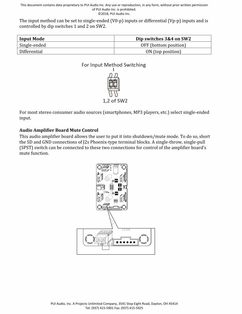
The input method can be set to single-ended (V0-p) inputs or differential (Vp-p) inputs and is controlled by dip switches 1 and 2 on SW2.
Input Mode Dip switches 3&4 on SW2
Single-ended OFF (bottom position)
Differential ON (top position)
For most stereo consumer audio sources (smartphones, MP3 players, etc.) select single-ended input.
Audio Amplifier Board Mute Control
This audio amplifier board allows the user to put it into shutdown/mute mode. To do so, short the SD and GND connections of J2s Phoenix-type terminal blocks. A single-throw, single-pull (SPST) switch can be connected to these two connections for control of the amplifier board’s mute function.

This document contains data proprietary to PUI Audio Inc. Any use or reproduction, in any form, without prior written permission of PUI Audio Inc. is prohibited.
©2018, PUI Audio Inc.
PUI Audio, Inc. A Projects Unlimited Company, 3541 Stop Eight Road, Dayton, OH 45414 Tel: (937) 415-5901 Fax: (937) 415-5925
Stereo/Two Channel Connection
1. Set the Output Mode to BTL and Input Mode to match the single input type.
2. Connect your stereo audio source: A) A stereo 3.5mm audio jack is provided for easy connection to your stereo audio source, such as a smartphone, MP3 player, or computer.
B) Two Phoenix-type screw terminal blocks on either side of the stereo 3.5mm jack (J4 and J8) may also be used to connect to your audio source. Ensure polarity is observed when using these terminal blocks (+ on outside terminations).
C) A six-circuit Molex® SL™ 70543 connector is also provided for differential audio signal input.
3. Connect your speakers to the Phoenix-type screw terminal blocks, J5 & J7 opposite the
stereo 3.5mm jack, ensuring polarity is observed (+ on outside terminations) for best bass response.
4. A 2.1mm x 5.5mm center-positive DC power jack is provided for quick power supply connection. Simply connect your 8 VDC to 19 VDC power supply, and the POWER LED will illuminate green.
The gain on this amplifier board is fixed at 26 dB. Please use your audio source device’s volume control to adjust the amplifier output. Alternatively, you can connect a 25 kOhm audio taper potentiometer between the audio source device and amplifier for the purpose of volume control.
Note: Only use one group of audio inputs at a time.
This document contains data proprietary to PUI Audio Inc. Any use or reproduction, in any form, without prior written permission of PUI Audio Inc. is prohibited.
©2018, PUI Audio Inc.
PUI Audio, Inc. A Projects Unlimited Company, 3541 Stop Eight Road, Dayton, OH 45414 Tel: (937) 415-5901 Fax: (937) 415-5925
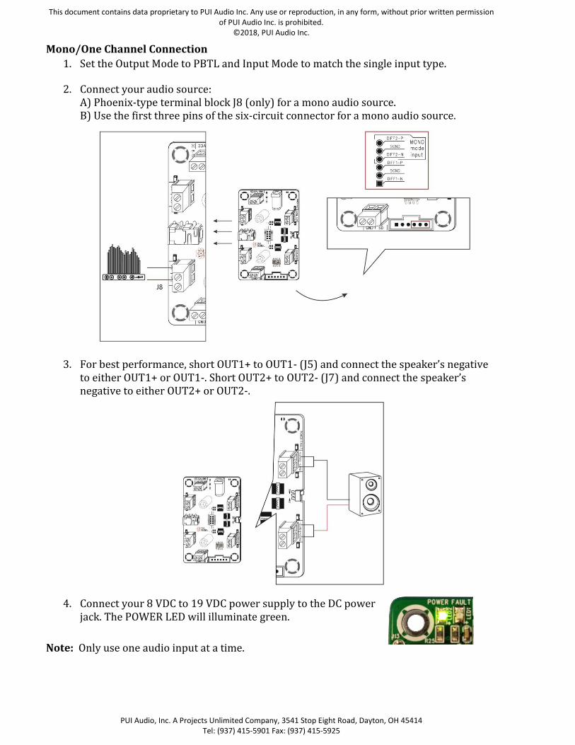
Mono/One Channel Connection
1. Set the Output Mode to PBTL and Input Mode to match the single input type.
2. Connect your audio source: A) Phoenix-type terminal block J8 (only) for a mono audio source. B) Use the first three pins of the six-circuit connector for a mono audio source.
3. For best performance, short OUT1+ to OUT1- (J5) and connect the speaker’s negative to either OUT1+ or OUT1-. Short OUT2+ to OUT2- (J7) and connect the speaker’s negative to either OUT2+ or OUT2-.
4. Connect your 8 VDC to 19 VDC power supply to the DC power
jack. The POWER LED will illuminate green.
Note: Only use one audio input at a time.

This document contains data proprietary to PUI Audio Inc. Any use or reproduction, in any form, without prior written permission of PUI Audio Inc. is prohibited.
©2018, PUI Audio Inc.
PUI Audio, Inc. A Projects Unlimited Company, 3541 Stop Eight Road, Dayton, OH 45414 Tel: (937) 415-5901 Fax: (937) 415-5925
Dimensions
Output Power vs Supply Voltage Stereo Speaker Output (BTL)
Mono Speaker Output (PBTL)
Fault Indication Light In the event that the input/output mode is incorrectly set (a dipswitch in the wrong position) or an overcurrent condition exists, the fault indication LED will illuminate and amplifier operation will cease. Remove power, correct the fault condition, and reapply power to clear the fault and resume amplifier operation.

This document contains data proprietary to PUI Audio Inc. Any use or reproduction, in any form, without prior written permission of PUI Audio Inc. is prohibited.
©2018, PUI Audio Inc.
PUI Audio, Inc. A Projects Unlimited Company, 3541 Stop Eight Road, Dayton, OH 45414 Tel: (937) 415-5901 Fax: (937) 415-5925
Specifications Revisions
Revision Description Date
- Released from Engineering 2/19/18
Note:
1. Unless otherwise specified: A. All dimensions are in millimeters. B. Default tolerances are ±0.5mm and angles are ±3°.
2. Specifications subject to change or withdrawal without notice. 3. This part is RoHS 2011/65/EU Compliant.

Mouser Electronics
Authorized Distributor
Click to View Pricing, Inventory, Delivery & Lifecycle Information: PUI Audio:
AMP2X15