Embed Size (px)
Citation preview

SERVICE MANUAL
SPLIT-TYPE, HEAT PUMP AIR CONDITIONERS
CONTENTS1.TECHNICAL CHANGES··································22. REFERENCE MANUAL··································23. SAFETY PRECAUTION··································34. FEATURES ·····················································75. SPECIFICATIONS···········································86. DATA ·····························································107. OUTLINES AND DIMENSIONS····················158. WIRING DIAGRAM·······································189. WIRING SPECIFICATIONS ··························21
10. REFRIGERANT SYSTEM DIAGRAM ··············2611. TROUBLESHOOTING···································2912. FUNCTION SETTING····································8513. MONITORING THE OPERATION DATA BY THE REMOTE CONTROLLER ············9114. EASY MAINTENANCE FUNCTION············10115. DISASSEMBLY PROCEDURE ···················10416. PARTS LIST ················································126
No.OC334REVISED EDITION-A
R410A
December 2005
Outdoor unit[model names]PUHZ-RP35VHAPUHZ-RP50VHA
PUHZ-RP60VHA
PUHZ-RP71VHA
PUHZ-RP100VHAPUHZ-RP125VHA
PUHZ-RP140VHA
PUHZ-RP100YHAPUHZ-RP125YHAPUHZ-RP140YHA
[Service Ref.]PUHZ-RP35VHAPUHZ-RP50VHAPUHZ-RP50VHA1
PUHZ-RP60VHAPUHZ-RP60VHA1
PUHZ-RP71VHAPUHZ-RP71VHA1
PUHZ-RP100VHAPUHZ-RP125VHAPUHZ-RP125VHA1
PUHZ-RP140VHAPUHZ-RP140VHA1
PUHZ-RP100YHAPUHZ-RP125YHAPUHZ-RP140YHA
PUHZ-RP60VHAPUHZ-RP71VHA
NOTE:This manual describes only service data of the outdoor units.
Revision:PUHZ-RP50VHA1
PUHZ-RP60VHA1
PUHZ-RP71VHA1
PUHZ-RP125VHA1
PUHZ-RP140VHA1 are addedin REVISED EDITION-A.•Some descriptions have beenmodified.
•Please void OC334
OC334A-1.qxp 05.12.14 1:02 PM Page 1
104
15 DISASSEMBLY PROCEDURE
OPERATING PROCEDURE PHOTOSPUHZ-RP35/50VHA PUHZ-RP50VHA1
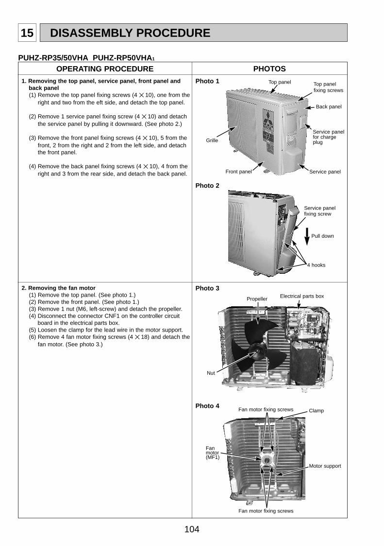
1. Removing the top panel, service panel, front panel and back panel(1) Remove the top panel fixing screws (4 ✕ 10), one from the
right and two from the eft side, and detach the top panel.
(2) Remove 1 service panel fixing screw (4 ✕ 10) and detach the service panel by pulling it downward. (See photo 2.)
(3) Remove the front panel fixing screws (4 ✕ 10), 5 from the front, 2 from the right and 2 from the left side, and detach the front panel.
(4) Remove the back panel fixing screws (4 ✕ 10), 4 from the right and 3 from the rear side, and detach the back panel.
2. Removing the fan motor(1) Remove the top panel. (See photo 1.)(2) Remove the front panel. (See photo 1.)(3) Remove 1 nut (M6, left-screw) and detach the propeller. (4) Disconnect the connector CNF1 on the controller circuit
board in the electrical parts box.(5) Loosen the clamp for the lead wire in the motor support. (6) Remove 4 fan motor fixing screws (4 ✕ 18) and detach the
fan motor. (See photo 3.)
Photo 1
Photo 2
Top panel Top panel fixing screws
Service panel
Service panel for charge plugGrille
Front panel
Back panel
4 hooks
Pull down
Service panel fixing screw
Photo 3
Propeller
Nut
Electrical parts box
Photo 4
Fan motor(MF1)
Fan motor fixing screws
Fan motor fixing screws
Motor support
Clamp
OC334A-4.qxp 05.12.14 1:12 PM Page 104

105
Electrical parts box Controller circuitboard (C.B.)
Electrical parts box fixingscrew
Terminalblock(TB1)
OPERATING PROCEDURE PHOTOS
4. Removing the thermistor <Outdoor 2-phase pipe> (TH6) and thermistor <Outdoor pipe> (TH3)(1) Remove the service panel. (See photo 2.)(2) Remove the top panel. (See photo 1.)(3) Remove the front panel. (See photo 1.)(4) Remove the back panel fixing screws, 4 from the right and
3 from the rear side, and detach the back panel. (See photo 1.)
(5) Disconnect the connector TH3 (white) or TH6/7 (red) on the controller circuit board in the electrical parts box.
(6) Loosen the clamp for the lead wire in the rear of the electrical parts box.
(7) Pull out the thermistor <Outdoor pipe> (TH3) and thermistor <Outdoor 2-phase pipe> (TH6) from the sensor holder.
Note: Replace the thermistor <Outdoor 2-phase pipe> (TH6)and the thermistor <Outdoor> (TH7) together since they are combined. Refer to No. 5. to remove the thermistor <Outdoor> (TH7).
3. Removing the electrical parts box(1) Remove the service panel. (See photo 2.)(2) Remove the top panel. (See photo 1.)(3) Remove the front panel. (See photo 1.)(4) Disconnect the indoor/outdoor connecting wire from
terminal block.(5) Remove all the following connectors from controller circuit board;
fan motor, linear expansion valve, thermistor<Outdoor pipe>,thermistor<Discharge>, thermistor<Outdoor 2-phase pipe>, thermistor<Outdoor>, high pressure switch, four-way valve and bypass valve. Pull out the disconnected wire from the electrical parts box.<Diagram symbol in the connector housing>
• Fan motor (CNF1) • Linear expansion valve (LEV-A and LEV-B) • Thermistor <Outdoor pipe> (TH3) • Thermistor <Discharge> (TH4) • Thermistor <Outdoor 2-phase pipe, Outdoor> (TH6/7) • High pressure switch (63H)
(6) Remove the terminal cover and disconnect the compressorlead wire.
(7) Remove the electrical parts box fixing screws, 1 from the front, the right and the rear side, and detach the electrical parts box by pulling it upward.
Photo 5
Motor forcompressor (MC)
Terminal cover
Photo 6
Thermistor <Outdoor 2-phase pipe>(TH6)
Clamp
Electrical parts box
Thermistor <Outdoor 2-phase pipe> (TH6)
OC334A-4.qxp 05.12.14 1:12 PM Page 105
106
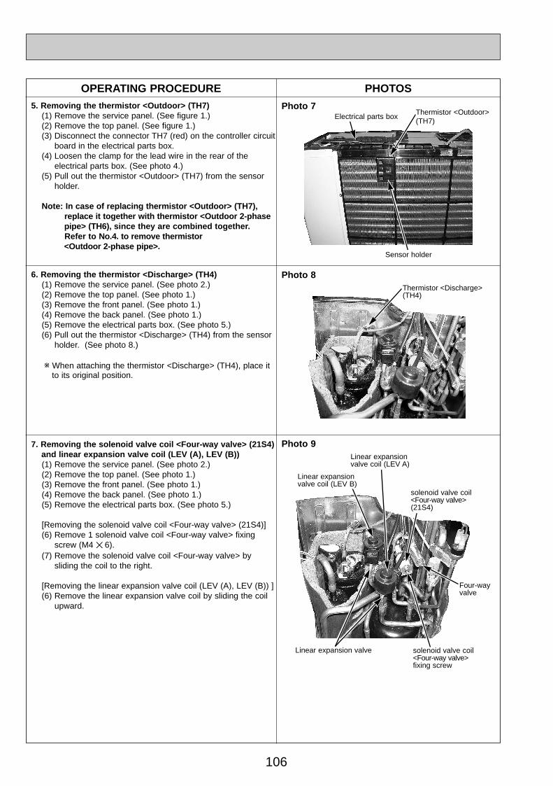
OPERATING PROCEDURE PHOTOS5. Removing the thermistor <Outdoor> (TH7)
(1) Remove the service panel. (See figure 1.)(2) Remove the top panel. (See figure 1.)(3) Disconnect the connector TH7 (red) on the controller circuit
board in the electrical parts box.(4) Loosen the clamp for the lead wire in the rear of the
electrical parts box. (See photo 4.)(5) Pull out the thermistor <Outdoor> (TH7) from the sensor
holder.
Note: In case of replacing thermistor <Outdoor> (TH7), replace it together with thermistor <Outdoor 2-phase pipe> (TH6), since they are combined together. Refer to No.4. to remove thermistor <Outdoor 2-phase pipe>.
Photo 7
Photo 9
6. Removing the thermistor <Discharge> (TH4)(1) Remove the service panel. (See photo 2.)(2) Remove the top panel. (See photo 1.)(3) Remove the front panel. (See photo 1.)(4) Remove the back panel. (See photo 1.)(5) Remove the electrical parts box. (See photo 5.)(6) Pull out the thermistor <Discharge> (TH4) from the sensor
holder. (See photo 8.)
w When attaching the thermistor <Discharge> (TH4), place it to its original position.
7. Removing the solenoid valve coil <Four-way valve> (21S4) and linear expansion valve coil (LEV (A), LEV (B))(1) Remove the service panel. (See photo 2.)(2) Remove the top panel. (See photo 1.)(3) Remove the front panel. (See photo 1.)(4) Remove the back panel. (See photo 1.)(5) Remove the electrical parts box. (See photo 5.)
[Removing the solenoid valve coil <Four-way valve> (21S4)](6) Remove 1 solenoid valve coil <Four-way valve> fixing
screw (M4 ✕ 6).(7) Remove the solenoid valve coil <Four-way valve> by
sliding the coil to the right.
[Removing the linear expansion valve coil (LEV (A), LEV (B)) ](6) Remove the linear expansion valve coil by sliding the coil
upward.
Thermistor <Outdoor>(TH7)
Sensor holder
Electrical parts box
Photo 8Thermistor <Discharge> (TH4)
solenoid valve coil<Four-way valve> fixing screw
Four-way valve
Linear expansion valve coil (LEV B)
Linear expansion valve coil (LEV A)
solenoid valve coil<Four-way valve> (21S4)
Linear expansion valve
OC334A-4.qxp 05.12.14 1:12 PM Page 106
107
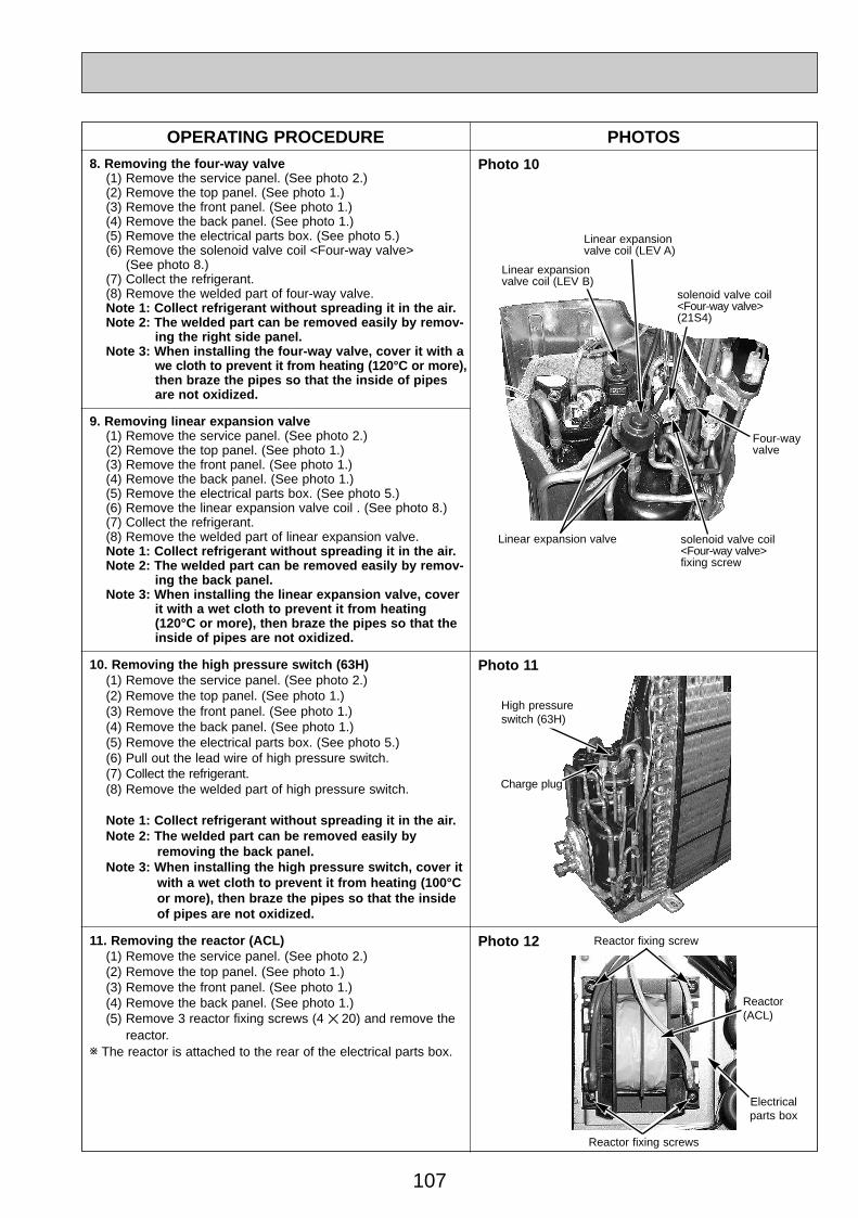
OPERATING PROCEDURE PHOTOS8. Removing the four-way valve
(1) Remove the service panel. (See photo 2.)(2) Remove the top panel. (See photo 1.)(3) Remove the front panel. (See photo 1.)(4) Remove the back panel. (See photo 1.)(5) Remove the electrical parts box. (See photo 5.)(6) Remove the solenoid valve coil <Four-way valve>
(See photo 8.)(7) Collect the refrigerant.(8) Remove the welded part of four-way valve.Note 1: Collect refrigerant without spreading it in the air.Note 2: The welded part can be removed easily by remov-
ing the right side panel.Note 3: When installing the four-way valve, cover it with a
we cloth to prevent it from heating (120°C or more), then braze the pipes so that the inside of pipesare not oxidized.
Photo 10
Photo 11
9. Removing linear expansion valve(1) Remove the service panel. (See photo 2.)(2) Remove the top panel. (See photo 1.)(3) Remove the front panel. (See photo 1.)(4) Remove the back panel. (See photo 1.)(5) Remove the electrical parts box. (See photo 5.)(6) Remove the linear expansion valve coil . (See photo 8.)(7) Collect the refrigerant.(8) Remove the welded part of linear expansion valve.Note 1: Collect refrigerant without spreading it in the air.Note 2: The welded part can be removed easily by remov-
ing the back panel.Note 3: When installing the linear expansion valve, cover
it with a wet cloth to prevent it from heating(120°C or more), then braze the pipes so that theinside of pipes are not oxidized.
10. Removing the high pressure switch (63H)(1) Remove the service panel. (See photo 2.)(2) Remove the top panel. (See photo 1.)(3) Remove the front panel. (See photo 1.)(4) Remove the back panel. (See photo 1.)(5) Remove the electrical parts box. (See photo 5.)(6) Pull out the lead wire of high pressure switch.(7) Collect the refrigerant.(8) Remove the welded part of high pressure switch.
Note 1: Collect refrigerant without spreading it in the air.Note 2: The welded part can be removed easily by
removing the back panel.Note 3: When installing the high pressure switch, cover it
with a wet cloth to prevent it from heating (100°C or more), then braze the pipes so that the inside of pipes are not oxidized.
Reactor fixing screw
High pressure switch (63H)
Reactor fixing screws
Reactor(ACL)
Electrical parts box
11. Removing the reactor (ACL)(1) Remove the service panel. (See photo 2.)(2) Remove the top panel. (See photo 1.)(3) Remove the front panel. (See photo 1.)(4) Remove the back panel. (See photo 1.)(5) Remove 3 reactor fixing screws (4 ✕ 20) and remove the
reactor.w The reactor is attached to the rear of the electrical parts box.
solenoid valve coil<Four-way valve> fixing screw
Four-way valve
Linear expansion valve coil (LEV B)
Linear expansion valve coil (LEV A)
solenoid valve coil<Four-way valve> (21S4)
Linear expansion valve
Photo 12
Charge plug
OC334A-4.qxp 05.12.14 1:12 PM Page 107
108
OPERATING PROCEDURE PHOTOS
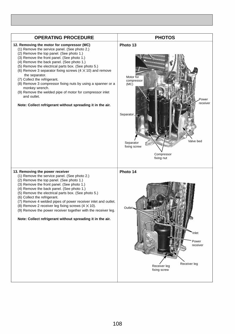
Photo 13
Photo 14
Motor forcompressor(MC)
Valve bed
Separator
Separatorfixing screw
Compressorfixing nut
Powerreceiver
Powerreceiver
Outlet
Inlet
12. Removing the motor for compressor (MC)(1) Remove the service panel. (See photo 2.)(2) Remove the top panel. (See photo 1.)(3) Remove the front panel. (See photo 1.)(4) Remove the back panel. (See photo 1.)(5) Remove the electrical parts box. (See photo 5.)(6) Remove 3 separator fixing screws (4 ✕ 10) and remove
the separator.(7) Collect the refrigerant.(8) Remove 3 compressor fixing nuts by using a spanner or a
monkey wrench.(9) Remove the welded pipe of motor for compressor inlet
and outlet.
Note: Collect refrigerant without spreading it in the air.
Receiver leg fixing screw
Receiver leg
13. Removing the power receiver (1) Remove the service panel. (See photo 2.)(2) Remove the top panel. (See photo 1.)(3) Remove the front panel. (See photo 1.)(4) Remove the back panel. (See photo 1.)(5) Remove the electrical parts box. (See photo 5.)(6) Collect the refrigerant.(7) Remove 4 welded pipes of power receiver inlet and outlet.(8) Remove 2 receiver leg fixing screws (4 ✕ 10).(9) Remove the power receiver together with the receiver leg.
Note: Collect refrigerant without spreading it in the air.
OC334A-4.qxp 05.12.14 1:12 PM Page 108
109
OPERATING PROCEDURE PHOTOS & ILLUSTRATION
PUHZ-RP60/ 71VHA PUHZ-RP60/ 71VHA1
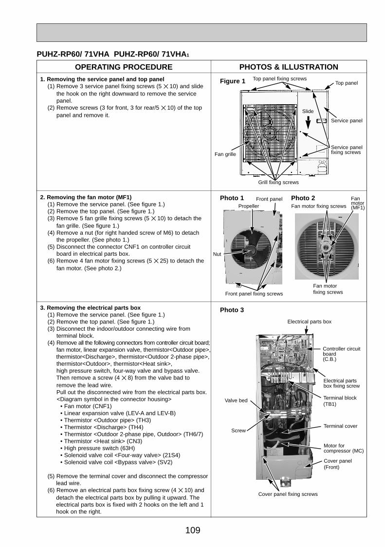
1. Removing the service panel and top panel(1) Remove 3 service panel fixing screws (5 ✕ 10) and slide
the hook on the right downward to remove the service panel.
(2) Remove screws (3 for front, 3 for rear/5 ✕ 10) of the top panel and remove it.
Figure 1 Top panel fixing screwsTop panel
Service panelfixing screws
Service panel
Grill fixing screws
Fan grille
2. Removing the fan motor (MF1)(1) Remove the service panel. (See figure 1.)(2) Remove the top panel. (See figure 1.)(3) Remove 5 fan grille fixing screws (5 ✕ 10) to detach the
fan grille. (See figure 1.)(4) Remove a nut (for right handed screw of M6) to detach
the propeller. (See photo 1.)(5) Disconnect the connector CNF1 on controller circuit
board in electrical parts box.(6) Remove 4 fan motor fixing screws (5 ✕ 25) to detach the
fan motor. (See photo 2.)
Fan motor fixing screws
Photo 3
Electrical parts box
Controller circuitboard(C.B.)
Electrical partsbox fixing screw
Terminal cover
Cover panel (Front)
Cover panel fixing screws
Motor forcompressor (MC)
Photo 1 Fan motor(MF1)
Fan motor fixing screws
PropellerFront panel
Front panel fixing screws
Nut
Terminal block(TB1)
Photo 2
Valve bed
Screw
Slide
3. Removing the electrical parts box(1) Remove the service panel. (See figure 1.)(2) Remove the top panel. (See figure 1.)(3) Disconnect the indoor/outdoor connecting wire from
terminal block.(4) Remove all the following connectors from controller circuit board;
fan motor, linear expansion valve, thermistor<Outdoor pipe>,thermistor<Discharge>, thermistor<Outdoor 2-phase pipe>, thermistor<Outdoor>, thermistor<Heat sink>, high pressure switch, four-way valve and bypass valve. Then remove a screw (4 ✕ 8) from the valve bad to remove the lead wire.Pull out the disconnected wire from the electrical parts box.<Diagram symbol in the connector housing>
• Fan motor (CNF1) • Linear expansion valve (LEV-A and LEV-B) • Thermistor <Outdoor pipe> (TH3) • Thermistor <Discharge> (TH4) • Thermistor <Outdoor 2-phase pipe, Outdoor> (TH6/7) • Thermistor <Heat sink> (CN3) • High pressure switch (63H) • Solenoid valve coil <Four-way valve> (21S4) • Solenoid valve coil <Bypass valve> (SV2)
(5) Remove the terminal cover and disconnect the compressorlead wire.
(6) Remove an electrical parts box fixing screw (4 ✕ 10) and detach the electrical parts box by pulling it upward. The electrical parts box is fixed with 2 hooks on the left and 1 hook on the right.
OC334A-4.qxp 05.12.14 1:12 PM Page 109
110
Thermistor <Outdoor 2-phase pipe>(TH6)
OPERATING PROCEDURE PHOTOS
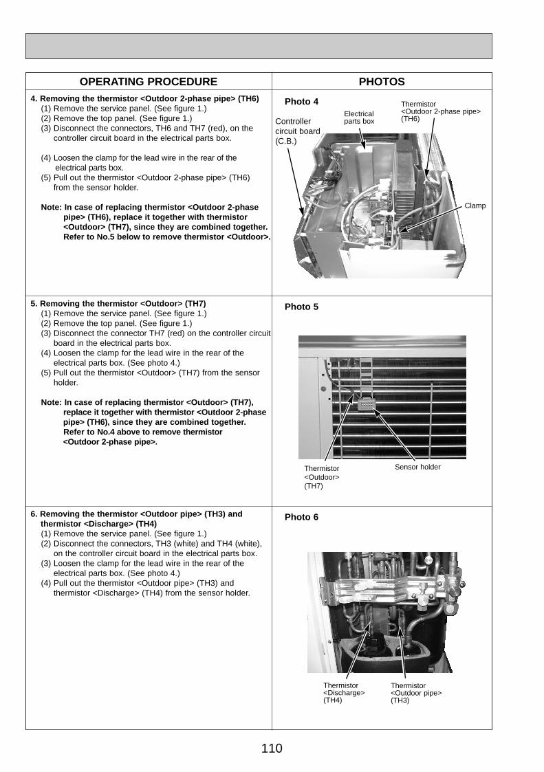
Photo 44. Removing the thermistor <Outdoor 2-phase pipe> (TH6)(1) Remove the service panel. (See figure 1.)(2) Remove the top panel. (See figure 1.)(3) Disconnect the connectors, TH6 and TH7 (red), on the
controller circuit board in the electrical parts box.
(4) Loosen the clamp for the lead wire in the rear of the electrical parts box.
(5) Pull out the thermistor <Outdoor 2-phase pipe> (TH6) from the sensor holder.
Note: In case of replacing thermistor <Outdoor 2-phase pipe> (TH6), replace it together with thermistor <Outdoor> (TH7), since they are combined together. Refer to No.5 below to remove thermistor <Outdoor>.
5. Removing the thermistor <Outdoor> (TH7)(1) Remove the service panel. (See figure 1.)(2) Remove the top panel. (See figure 1.)(3) Disconnect the connector TH7 (red) on the controller circuit
board in the electrical parts box.(4) Loosen the clamp for the lead wire in the rear of the
electrical parts box. (See photo 4.)(5) Pull out the thermistor <Outdoor> (TH7) from the sensor
holder.
Note: In case of replacing thermistor <Outdoor> (TH7), replace it together with thermistor <Outdoor 2-phase pipe> (TH6), since they are combined together. Refer to No.4 above to remove thermistor <Outdoor 2-phase pipe>.
Photo 6
Clamp
6. Removing the thermistor <Outdoor pipe> (TH3) and thermistor <Discharge> (TH4)(1) Remove the service panel. (See figure 1.)(2) Disconnect the connectors, TH3 (white) and TH4 (white),
on the controller circuit board in the electrical parts box.(3) Loosen the clamp for the lead wire in the rear of the
electrical parts box. (See photo 4.)(4) Pull out the thermistor <Outdoor pipe> (TH3) and
thermistor <Discharge> (TH4) from the sensor holder.
Electrical parts box
Photo 5
Thermistor<Outdoor>(TH7)
Sensor holder
Thermistor<Discharge> (TH4)
Thermistor <Outdoor pipe> (TH3)
Controller circuit board(C.B.)
OC334A-4.qxp 05.12.14 1:12 PM Page 110

111
OPERATING PROCEDURE PHOTOS7. Removing the solenoid valve coil <Four-way valve> (21S4),
linear expansion valve coil (LEV(A), LEV(B)) and solenoid valve coil <Bypass valve> (SV)(1) Remove the service panel. (See figure 1.)(2) Remove the top panel. (See figure 1.)(3) Remove the electrical parts box. (See photo 3.)[Removing the solenoid valve coil <Four-way valve>](4) Remove solenoid valve coil <Four-way valve> fixing screw
(M4 ✕ 6).(5) Remove the solenoid valve coil <Four-way valve> by
sliding the coil toward you.(6) Disconnect the connector 21S4 (green) on the controller
board in the electrical parts box.[Removing the linear expansion valve coil](4) Remove the linear expansion valve coil by sliding the coil upward.(5) Disconnect the connectors, LEV A (white) and LEV B (red),
on the controller circuit board in the electrical parts box.[Removing the solenoid valve coil <Bypass valve>](4) Remove the solenoid valve coil <Bypass valve> fixing screw
(M4 ✕ 6).(5) Remove the solenoid valve coil <Bypass valve> by sliding the
coil upward.(6) Disconnect the connector SV2 (blue) on the controller
circuit board in the electrical parts box.
8. Removing the four-way valve(1) Remove the service panel. (See figure 1.)(2) Remove the top panel. (See figure 1.)(3) Remove the electrical parts box. (See photo 3.)(4) Remove 3 valve bed fixing screws (4 ✕ 10) and 4 ball
valve and stop valve fixing screws (5 ✕ 16) and then remove the valve bed.
(5) Remove 3 right side panel fixing screw (5 ✕ 10) in the rear of the unit and then remove the right side panel.
(6) Remove the solenoid valve coil <Four-way valve>. (See photo 7.)
(7) Collect the refrigerant.(8) Remove the welded part of four-way valve.Note 1: Collect refrigerant without spreading it in the air.Note 2: The welded part can be removed easily by remov-
ing the right side panel.Note 3: When installing the four-way valve, cover it with a wet
cloth to prevent it from heating (120°C or more), thenbraze the pipes so that the inside of pipes are not oxi-dized.
9. Removing the linear expansion valve(1) Remove the service panel. (See figure 1.)(2) Remove the top panel. (See figure 1.)(3) Remove the electrical parts box. (See photo 3.)(4) Remove 3 valve bed fixing screws (4 ✕ 10) and 4 ball
valve and stop valve fixing screws (5 ✕ 16) and then remove the valve bed.
(5) Remove 3 right side panel fixing screw (5 ✕ 10) in the rear of the unit and then remove the right side panel.
(6) Remove the linear expansion valve. (See photo 7.)(7) Collect the refrigerant.(8) Remove the welded part of linear expansion valve.Note 1: Collect refrigerant without spreading it in the air.Note 2: The welded part can be removed easily by remov-
ing the right side panel.Note 3: When installing the linear expansion valve, cover
it with a wet cloth to prevent it from heating(120°C or more), then braze the pipes so that theinside of pip-es are not oxidized.
Photo 7
Photo 8
solenoid valve coil<Four-way valve> fixing screw
Four-way valve
Linear expansion valve coil (LEV B)
Linear expansion valve coil (LEV A)
Solenoid valve coil <Bypass valve> fixing screw
Linear expansion valve coil (LEV B)
Linear expansion valve coil (LEV A)
Linear expansion valve Four-way
valve
Linearexpansion valve
Solenoid valve coil <Bypass valve> (SV)
solenoid valve coil<Four-way valve> (21S4)
solenoid valve coil<Four-way valve> (21S4)
Bypass valve
Solenoid valve coil <Bypass valve> (SV)
Charge plug(High pressure)
Charge plug(Low pressure)
Stop valve
OC334A-4.qxp 05.12.14 1:12 PM Page 111

112
OPERATING PROCEDURE PHOTOS10. Removing the bypass valve
(1) Remove the service panel. (See figure 1.)(2) Remove the top panel. (See figure 1.)(3) Remove the electrical parts box. (See photo 3.)(4) Remove 3 right side panel fixing screws (5 ✕ 10) in the
rear of the unit and remove the right side panel.(5) Remove the bypass valve solenoid coil. (See photo 7.).(6) Collect the refrigerant.(7) Remove the welded part of bypass valve.
Note 1: Collect refrigerant without spreading it in the air.Note 2: The welded part can be removed easily by
removing the right side panel.
12. Removing the reactor (ACL)(1) Remove the service panel. (See figure 1.)(2) Remove the top panel. (See figure 1.)(3) Remove the electrical parts box. (See photo 3.)(4) Remove 3 reactor fixing screws (4 ✕ 16) and remove the
reactor.w The reactor is attached to the rear of the electrical parts box.
Photo 9
Reactor fixing screw
11. Removing the high pressure switch (63H)(1) Remove the service panel. (See figure 1.)(2) Remove the top panel. (See figure 1.)(3) Remove the electrical parts box. (See photo 3.)(4) Remove 3 right side panel fixing screws (5 ✕ 10) in the
rear of the unit and remove the right side panel.(5) Pull out the lead wire of high pressure switch.(6) Collect the refrigerant.(7) Remove the welded part of high pressure switch.
Note 1: Collect refrigerant without spreading it in the air.Note 2: The welded part can be removed easily by
removing the right side panel.Note 3: When installing the high pressure switch, cover it
with a wet cloth to prevent it from heating (100°C or more), then braze the pipes so that the inside of pipes are not oxidized.
Linear expansion valve coil (LEV B)
Linear expansion valve coil (LEV A)
Linear expansion valve
Bypass valve
Four-way valve
Lead wire of high pressure switch
High pressure switch (63H)
Reactor fixing screws
Reactor(ACL)
Photo 10
Photo 11
Linearexpansion valve
Electrical parts box
Solenoid valve coil <Bypass valve> (SV)
Solenoid valve coil<Four-way valve> (21S4)
OC334A-4.qxp 05.12.14 1:12 PM Page 112

113
OPERATING PROCEDURE PHOTOS13. Removing the motor for compressor (MC)
(1) Remove the service panel. (See figure 1.)(2) Remove the top panel. (See figure 1.)(3) Remove 2 front cover panel fixing screws (5 ✕ 10) and
remove the front cover panel. (See photo 3.)(4) Remove 2 back cover panel fixing screws (5 ✕ 10) and
remove the back cover panel.(5) Remove the electrical parts box. (See photo 3.)(6) Remove 3 valve bed fixing screws (4 ✕ 10) and 4 ball valve
and stop valve fixing screws (5 ✕ 16) and then remove the valve bed.
(7) Remove 3 right side panel fixing screw (5 ✕ 10) in the rearof the unit and then remove the right side panel.
(8) Remove 3 separator fixing screws (4 ✕ 10) and remove the separator.
(9) Collect the refrigerant.(10) Remove the 3 points of the motor for compressor fixing
nut using a spanner or a monkey wrench.(11) Remove the welded pipe of motor for compressor inlet
and outlet and then remove the compressor.
Note: Collect refrigerant without spreading it in the air.
14. Removing the power receiver (1) Remove the service panel. (See figure 1.)(2) Remove the top panel. (See figure 1.)(3) Remove 2 front cover panel fixing screws (5 ✕ 10) and
remove the front cover panel. (See photo 3.)(4) Remove 2 back cover panel fixing screws (5 ✕ 10) and
remove the back cover panel.(5) Remove the electrical parts box. (See photo 3.)(6) Remove 3 valve bed fixing screws (4 ✕ 10) and 4 ball valve
and stop valve fixing screws (5 ✕ 16) and then remove the valve bed.
(7) Remove 3 right side panel fixing screw (5 ✕ 10) in the rear of the unit and then remove the right side panel.
(8) Collect the refrigerant.(9) Remove 4 welded pipes of power receiver inlet and outlet.(10) Remove 2 receiver leg fixing screws (4 ✕ 10).
Note: Collect refrigerant without spreading it in the air.
Photo 12
Receiver leg fixing screws
Motor forcompressor(MC)
Valve bedfixingscrews
Valve bed
Separator
Separatorfixing screw
Compressorfixing nut
Powerreceiver
Powerreceiver
Receiverleg
Inlet
Outlet
Photo 13
OC334A-4.qxp 05.12.14 1:12 PM Page 113

114
OPERATING PROCEDURE PHOTOS & ILLUSTRATION
PUHZ-RP100/ 125/ 140VHA PUHZ-RP125/ 140VHA1
1. Removing the service panel and top panel(1) Remove 3 service panel fixing screws (5 ✕ 10) and slide
the hook on the right downward to remove the service panel.
(2) Remove screws (3 for front, 3 for rear/5 ✕ 10) of the top panel and remove it.
Figure 1 Top panel fixing screws Top panel
Service panelfixing screws
Service panel
Grille fixing screws
Fan grille
2. Removing the fan motor (MF1, MF2)(1) Remove the service panel. (See figure 1.)(2) Remove the top panel. (See figure 1.)(3) Remove 5 fan grille fixing screws (5 ✕ 10) to detach the
fan grille. (See figure 1.)(4) Remove a nut (for right handed screw of M6) to detach
the propeller. (See photo 1.)(5) Disconnect the connectors, CNF1, CNF2 on controller
circuit board in electrical parts box.(6) Remove 4 fan motor fixing screws (5 ✕ 25) to detach the
fan motor. (See photo 2.)
Fan motor fixing screws
Photo 33. Removing the electrical parts box(1) Remove the service panel. (See figure 1.)(2) Remove the top panel. (See figure 1.)(3) Disconnect the indoor/outdoor connecting wire from
terminal block.(4) Remove all the following connectors from controller circuit board;
fan motor, linear expansion valve, thermistor <Outdoor pipe>,thermistor <Discharge>, thermistor <Outdoor 2-phase pipe>, thermistor <Outdoor>, high pressure switch, low pressure switch, solenoid valve coil <Four-way valve> and solenoid valve coil <Bypass valve>. Then remove a screw (4 ✕ 8) from the valve bad to remove the lead wire.Pull out the disconnected wire from the electrical parts box.<Diagram symbol in the connector housing>
• Fan motor (CNF1, CNF2) • Linear expansion valve (LEV-A and LEV-B) • Thermistor <Outdoor pipe> (TH3) • Thermistor <Discharge> (TH4) • Thermistor <Outdoor 2-phase pipe, Outdoor> (TH6/7) • High pressure switch (63H) • Low pressure switch (63L) • Solenoid valve coil <Four-way valve> (21S4) • Solenoid valve coil <Bypass valve> (SV2)
(5) Remove the terminal cover and disconnect the compressor lead wire.
(6) Remove an electrical parts box fixing screw (4 ✕ 10) and detach the electrical parts box by pulling it upward. The electrical parts box is fixed with 2 hooks on the left and 1 hook on the right.
Electrical parts box
Controller circuit board(C.B.)
Electrical partsbox fixing screw
Terminal cover
Cover panel (Front)
Cover panel fixing screws
Motor forcompressor(MC)
Photo 1 Fanmotor
Fan motor fixing screws
PropellerFront panel
Nut
Terminal block(TB1)
Photo 2
Valve bed
Screw
Grille fixing screws
Slide
OC334A-4.qxp 05.12.14 1:12 PM Page 114
115
OPERATING PROCEDURE PHOTOS
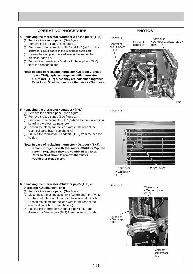
Photo 44. Removing the thermistor <Outdoor 2-phase pipe> (TH6)(1) Remove the service panel. (See figure 1.)(2) Remove the top panel. (See figure 1.)(3) Disconnect the connectors, TH6 and TH7 (red), on the
controller circuit board in the electrical parts box.(4) Loosen the clamp for the lead wire in the rear of the
electrical parts box.(5) Pull out the thermistor <Outdoor 2-phase pipe> (TH6)
from the sensor holder.
Note: In case of replacing thermistor <Outdoor 2-phase pipe> (TH6), replace it together with thermistor <Outdoor> (TH7) since they are combined together. Refer to No.5 below to remove thermistor <Outdoor>.
5. Removing the thermistor <Outdoor> (TH7)(1) Remove the service panel. (See figure 1.)(2) Remove the top panel. (See figure 1.)(3) Disconnect the connector TH7 (red) on the controller circuit
board in the electrical parts box.(4) Loosen the clamp for the lead wire in the rear of the
electrical parts box. (See photo 4.)(5) Pull out the thermistor <Outdoor> (TH7) from the sensor
holder.
Note: In case of replacing thermistor <Outdoor> (TH7), replace it together with thermistor <Outdoor 2-phase pipe> (TH6), since they are combined together. Refer to No.4 above to remove thermistor <Outdoor 2-phase pipe>.
Photo 6
Clamp
Controller circuit board(C.B.)
Thermistor <Outdoor 2-phase pipe>(TH6)
6. Removing the thermistor <Outdoor pipe> (TH3) and thermistor <Discharge> (TH4)(1) Remove the service panel. (See figure 1.)(2) Disconnect the connectors, TH3 (white) and TH4 (white),
on the controller circuit board in the electrical parts box.(3) Loosen the clamp for the lead wire in the rear of the
electrical parts box. (See photo 4.)(4) Pull out the thermistor <Outdoor pipe> (TH3) and
thermistor <Discharge> (TH4) from the sensor holder.
Electrical parts box
Photo 5
Thermistor <Outdoor>(TH7)
Sensor holder
Thermistor <Discharge> (TH4)
Thermistor <Outdoor pipe>(TH3)
Motor forcompressor(MC)
OC334A-4.qxp 05.12.14 1:12 PM Page 115

116
Solenoid valve coil<Four-way valve> (21S4)
OPERATING PROCEDURE PHOTOS7. Removing the solenoid valve coil <Four-way valve> (21S4),
and linear expansion valve coil (LEV(A), LEV(B))(1) Remove the service panel. (See figure 1.)(2) Remove the top panel. (See figure 1.)
[Removing the solenoid valve coil <Four-way valve>](3) Remove four-way valve solenoid coil fixing screw
(M4 ✕ 6).(4) Remove the solenoid valve coil <Four-way valve> by
sliding the coil toward you.(5) Disconnect the connector 21S4 (green) on the controller
circuit board in the electrical parts box.
[Removing the linear expansion valve coil](3) Remove the linear expansion valve coil by sliding the coil
upward.(4) Disconnect the connectors, LEV A (white) and LEV B (red),
on the controller circuit board in the electrical parts box.
8. Removing the four-way valve(1) Remove the service panel. (See figure 1.)(2) Remove the top panel. (See figure 1.)(3) Remove 3 valve bed fixing screws (4 ✕ 10) and 4 ball
valve and stop valve fixing screws (5 ✕ 16) and then remove the valve bed.
(4) Remove 4 right side panel fixing screw (5 ✕ 10) in the rear of the unit and then remove the right side panel.
(5) Remove the solenoid valve coil <Four-way valve>. (See photo 7.)
(6) Collect the refrigerant.(7) Remove the welded part of four-way valve.Note 1: Collect refrigerant without spreading it in the air.Note 2: The welded part can be removed easily by remov-
ing the right side panel.Note 3: When installing the four-way valve, cover it with a
wet cloth to prevent it from heating (120°C or more), then braze the pipes so that the inside of pipesare not oxidized.
9. Removing linear expansion valve(1) Remove the service panel. (See figure 1.)(2) Remove the top panel. (See figure 1.)(3) Remove 3 valve bed fixing screws (4 ✕ 10) and 4 ball
valve and stop valve fixing screws (5 ✕ 16) and then remove the valve bed.
(4) Remove 4 right side panel fixing screw (5 ✕ 10) in the rear of the unit and then remove the right side panel.
(5) Remove the linear expansion valve. (See photo 7.)(6) Collect the refrigerant.(7) Remove the welded part of linear expansion valve.Note 1: Collect refrigerant without spreading it in the air.Note 2: The welded part can be removed easily by remov-
ing the right side panel.Note 3: When installing the linear expansion valve, cover
it with a wet cloth to prevent it from heating(120°C or more), then braze the pipes so that theinside of pip-es are not oxidized.
Photo 7
Photo 8
Four-wayvalve
Linear expansion valve coil (LEV A)
Linear expansion valve coil (LEV B)
Linear expansion valve coil (LEV A)
Four-way valve
Linear expansion valve
Linear expansion valve coil (LEV B)
Linear expansion valve
Solenoid valve coil<Four-way valve> fixing screw
Charge plug(High pressure)
Charge plug(Low pressure)
OC334A-4.qxp 05.12.14 1:12 PM Page 116
117
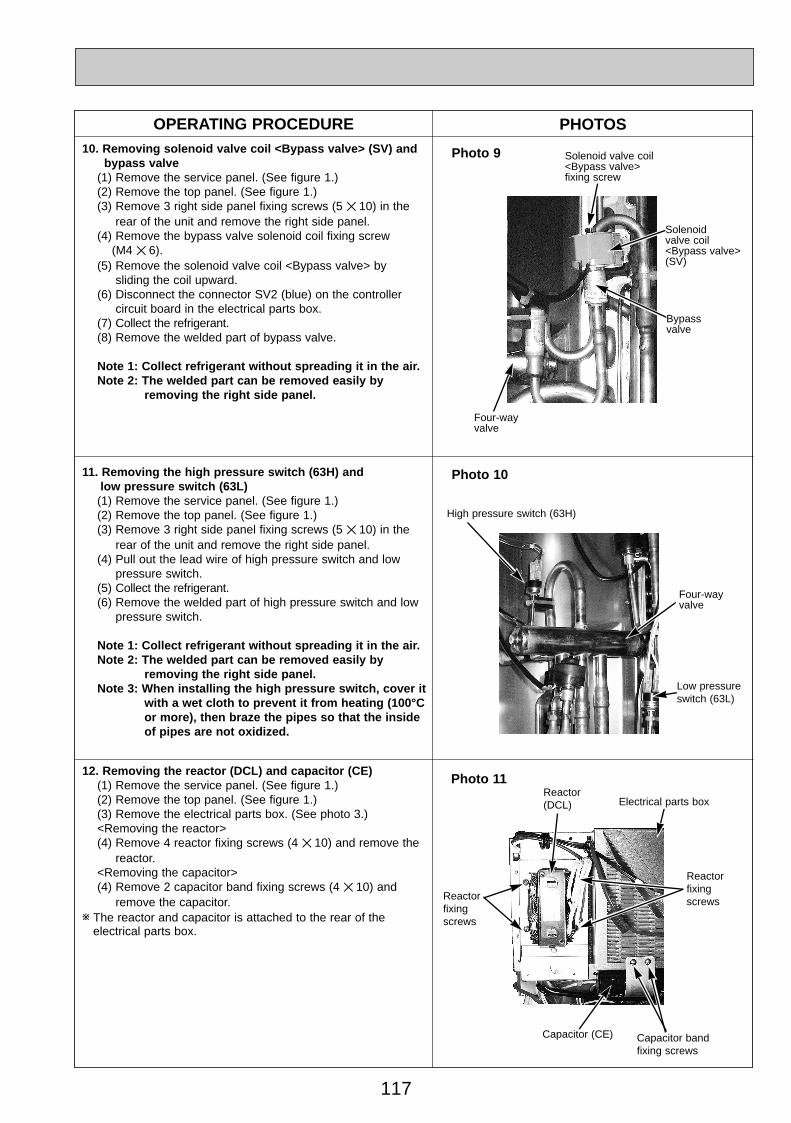
OPERATING PROCEDURE PHOTOS10. Removing solenoid valve coil <Bypass valve> (SV) and
bypass valve(1) Remove the service panel. (See figure 1.)(2) Remove the top panel. (See figure 1.)(3) Remove 3 right side panel fixing screws (5 ✕ 10) in the
rear of the unit and remove the right side panel.(4) Remove the bypass valve solenoid coil fixing screw
(M4 ✕ 6).(5) Remove the solenoid valve coil <Bypass valve> by
sliding the coil upward.(6) Disconnect the connector SV2 (blue) on the controller
circuit board in the electrical parts box.(7) Collect the refrigerant.(8) Remove the welded part of bypass valve.
Note 1: Collect refrigerant without spreading it in the air.Note 2: The welded part can be removed easily by
removing the right side panel.
12. Removing the reactor (DCL) and capacitor (CE)(1) Remove the service panel. (See figure 1.)(2) Remove the top panel. (See figure 1.)(3) Remove the electrical parts box. (See photo 3.)<Removing the reactor>(4) Remove 4 reactor fixing screws (4 ✕ 10) and remove the
reactor.<Removing the capacitor>(4) Remove 2 capacitor band fixing screws (4 ✕ 10) and
remove the capacitor.w The reactor and capacitor is attached to the rear of the
electrical parts box.
Photo 9
Capacitor band fixing screws
11. Removing the high pressure switch (63H) and low pressure switch (63L)(1) Remove the service panel. (See figure 1.)(2) Remove the top panel. (See figure 1.)(3) Remove 3 right side panel fixing screws (5 ✕ 10) in the
rear of the unit and remove the right side panel.(4) Pull out the lead wire of high pressure switch and low
pressure switch.(5) Collect the refrigerant.(6) Remove the welded part of high pressure switch and low
pressure switch.
Note 1: Collect refrigerant without spreading it in the air.Note 2: The welded part can be removed easily by
removing the right side panel.Note 3: When installing the high pressure switch, cover it
with a wet cloth to prevent it from heating (100°C or more), then braze the pipes so that the inside of pipes are not oxidized.
Bypass valve
High pressure switch (63H)
Photo 10
Photo 11
Four-way valve
Reactor fixing screws
Reactor fixing screws
Reactor(DCL) Electrical parts box
Capacitor (CE)
Solenoid valve coil <Bypass valve> fixing screw
Solenoid valve coil <Bypass valve> (SV)
Low pressure switch (63L)
Four-way valve
OC334A-4.qxp 05.12.14 1:12 PM Page 117

118
OPERATING PROCEDURE PHOTOS13. Removing the motor for compressor (MC)
(1) Remove the service panel. (See figure 1.)(2) Remove the top panel. (See figure 1.)(3) Remove 2 front cover panel fixing screws (5 ✕ 10) and
remove the front cover panel. (See photo 3.)(4) Remove 2 back cover panel fixing screws (5 ✕ 10) and
remove the back cover panel.(5) Remove the electrical parts box. (See photo 3.)(6) Remove 3 valve bed fixing screws (4 ✕ 10) and 4 ball valve
and stop valve fixing screws (5 ✕ 16) and then remove the valve bed.
(7) Remove 3 right side panel fixing screw (5 ✕ 10) in the rearof the unit and then remove the right side panel.
(8) Remove 3 separator fixing screws (4 ✕ 10) and remove the separator.
(9) Collect the refrigerant.(10) Remove the 3 points of the motor for compressor fixing
nut using a spanner or a monkey wrench.(11) Remove the welded pipe of motor for compressor inlet
and outlet and then remove the compressor.
Note: Collect refrigerant without spreading it in the air.
14. Removing the power receiver (1) Remove the service panel. (See figure 1.)(2) Remove the top panel. (See figure 1.)(3) Remove 2 front cover panel fixing screws (5 ✕ 10) and
remove the front cover panel. (See photo 3.)(4) Remove 2 back cover panel fixing screws (5 ✕ 10) and
remove the back cover panel.(5) Remove the electrical parts box. (See photo 3.)(6) Remove 3 valve bed fixing screws (4 ✕ 10) and 4 ball valve
and stop valve fixing screws (5 ✕ 16) and then remove the valve bed.
(7) Remove 3 right side panel fixing screw (5 ✕ 10) in the rear of the unit and then remove the right side panel.
(8) Collect the refrigerant.(9) Remove 4 welded pipes of power receiver inlet and outlet.(10) Remove 2 receiver leg fixing screws (4 ✕ 10).
Note: Collect refrigerant without spreading it in the air.
Photo 12
Motor forcompressor(MC)
Valve bed
Separator
Separatorfixing screw
Powerreceiver
Photo 13
Valve bedfixingscrews
Compressorfixing nut
Receiver leg fixing screws
Powerreceiver
Receiverleg
Inlet
Outlet
Motor forcompressor(MC)
OC334A-4.qxp 05.12.14 1:12 PM Page 118
119
OPERATING PROCEDURE PHOTOS & ILLUSTRATION
PUHZ-RP100YHA PUHZ-RP125YHA PUHZ-RP140YHA
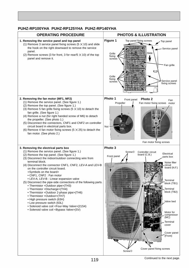
1. Removing the service panel and top panel(1) Remove 3 service panel fixing screws (5 ✕ 10) and slide
the hook on the right downward to remove the service panel.
(2) Remove screws (3 for front, 3 for rear/5 ✕ 10) of the top panel and remove it.
Figure 1 Top panel fixing screws Top panel
Service panelfixing screws
Service panel
Grille fixing screws
Fan grille
2. Removing the fan motor (MF1, MF2)(1) Remove the service panel. (See figure 1.)(2) Remove the top panel. (See figure 1.)(3) Remove 5 fan grille fixing screws (5 ✕ 10) to detach the
fan grille. (See figure 1.)(4) Remove a nut (for right handed screw of M6) to detach
the propeller. (See photo 1.)(5) Disconnect the connectors, CNF1 and CNF2 on controller
circuit board in electrical parts box.(6) Remove 4 fan motor fixing screws (5 ✕ 25) to detach the
fan motor. (See photo 2.)
Fan motor fixing screws
Photo 33. Removing the electrical parts box(1) Remove the service panel. (See figure 1.)(2) Remove the top panel. (See figure 1.)(3) Disconnect the indoor/outdoor connecting wire from
terminal block.(4) Disconnect the connector CNF1, CNF2, LEV-A and LEV-B
on the controller circuit board.<Symbols on the board>• CNF1, CNF2 : Fan motor• LEV-A, LEV-B : Linear expansion valve
(5) Disconnect the pipe-side connections of the following parts.• Thermistor <Outdoor pipe>(TH3)• Thermistor <Discharge>(TH4)• Thermistor <Outdoor 2-phase pipe>(TH6)• Thermistor <Outdoor>(TH7)• High pressure switch (63H)• Low pressure switch (63L)• Solenoid valve coil <Four-Way Valve>(21S4)• Solenoid valve coil <Bypass Valve>(SV)
Electrical parts box
Noise filter circuitboard (N.F.)
Terminal cover
Cover panel fixing screws
Motor forcompressor(MC)
Photo 1 Fanmotor
Fan motor fixing screws
PropellerFront panel
Nut
Photo 2
Valve bed
Screw9
Grille fixing screws
Slide
Terminal block (TB2)
Screw8
Front panel
Continued to the next page.
Controller circuit board (C.B.)
Terminalblock (TB1)
Cover panel (Front)
OC334A-4.qxp 05.12.14 1:12 PM Page 119
120
OPERATING PROCEDURE PHOTOS & ILLUSTRATION
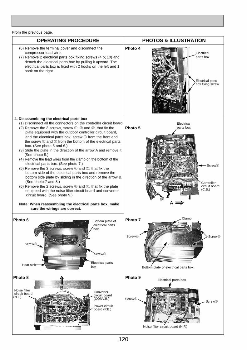
4. Disassembling the electrical parts box(1) Disconnect all the connectors on the controller circuit board.(2) Remove the 3 screws, screw 1, 2 and 3, that fix the
plate equipped with the outdoor controller circuit board, and the electrical parts box, screw 1 from the front and the screw 2 and 3 from the bottom of the electrical partsbox. (See photo 5 and 6.)
(3) Slide the plate in the direction of the arrow A and remove it.(See photo 5.)
(4) Remove the lead wires from the clamp on the bottom of the electrical parts box. (See photo 7.)
(5) Remove the 3 screws, screw 4 and 5, that fix the bottom side of the electrical parts box and remove the bottom side plate by sliding in the direction of the arrow B. (See photo 7 and 8.)
(6) Remove the 2 screws, screw 6 and 7, that fix the plate equipped with the noise filter circuit board and convertercircuit board. (See photo 9.)
Note: When reassembling the electrical parts box, make sure the wirings are correct.
Photo 4(6) Remove the terminal cover and disconnect the compressor lead wire.
(7) Remove 2 electrical parts box fixing screws (4 ✕ 10) anddetach the electrical parts box by pulling it upward. The electrical parts box is fixed with 2 hooks on the left and 1 hook on the right.
Electrical parts box
Electrical partsbox fixing screw
From the previous page.
Photo 5Electrical parts box
Screw1
Controller circuit board (C.B.)
Photo 6
Screw3
Screw2
Bottom plate ofelectrical partsbox
A
Electrical partsbox
Photo 7
Screw5Screw4
Bottom plate of electrical parts box
Clamp
Photo 8
Power circuit board (P.B.)
Noise filtercircuit board
(N.F.)
Photo 9
Screw6
Noise filter circuit board (N.F.)
Electrical parts box
B
Heat sink
Screw7
Convertercircuit board (CONV.B.)
OC334A-4.qxp 05.12.14 1:12 PM Page 120
121
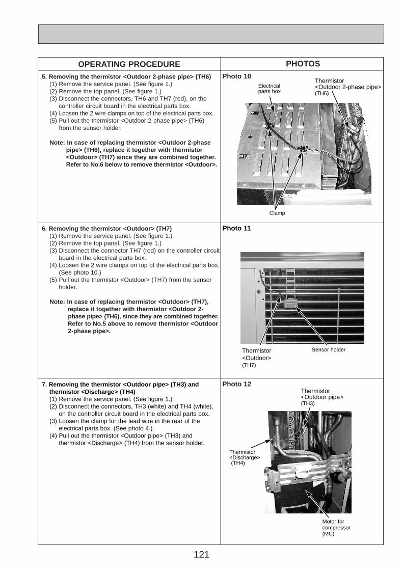
OPERATING PROCEDURE PHOTOSPhoto 105. Removing the thermistor <Outdoor 2-phase pipe> (TH6)
(1) Remove the service panel. (See figure 1.)(2) Remove the top panel. (See figure 1.)(3) Disconnect the connectors, TH6 and TH7 (red), on the
controller circuit board in the electrical parts box.(4) Loosen the 2 wire clamps on top of the electrical parts box.(5) Pull out the thermistor <Outdoor 2-phase pipe> (TH6)
from the sensor holder.
Note: In case of replacing thermistor <Outdoor 2-phase pipe> (TH6), replace it together with thermistor <Outdoor> (TH7) since they are combined together. Refer to No.6 below to remove thermistor <Outdoor>.
6. Removing the thermistor <Outdoor> (TH7)(1) Remove the service panel. (See figure 1.)(2) Remove the top panel. (See figure 1.)(3) Disconnect the connector TH7 (red) on the controller circuit
board in the electrical parts box.(4) Loosen the 2 wire clamps on top of the electrical parts box.
(See photo 10.)(5) Pull out the thermistor <Outdoor> (TH7) from the sensor
holder.
Note: In case of replacing thermistor <Outdoor> (TH7), replace it together with thermistor <Outdoor 2- phase pipe> (TH6), since they are combined together. Refer to No.5 above to remove thermistor <Outdoor 2-phase pipe>.
Photo 12
Clamp
Thermistor <Outdoor 2-phase pipe>(TH6)
7. Removing the thermistor <Outdoor pipe> (TH3) and thermistor <Discharge> (TH4)(1) Remove the service panel. (See figure 1.)(2) Disconnect the connectors, TH3 (white) and TH4 (white),
on the controller circuit board in the electrical parts box.(3) Loosen the clamp for the lead wire in the rear of the
electrical parts box. (See photo 4.)(4) Pull out the thermistor <Outdoor pipe> (TH3) and
thermistor <Discharge> (TH4) from the sensor holder.
Electrical parts box
Photo 11
Thermistor <Outdoor>(TH7)
Sensor holder
Thermistor <Discharge> (TH4)
Thermistor <Outdoor pipe>(TH3)
Motor forcompressor(MC)
OC334A-5.qxp 05.12.14 1:14 PM Page 121
122
Solenoid valve coil<Four-way valve> (21S4)
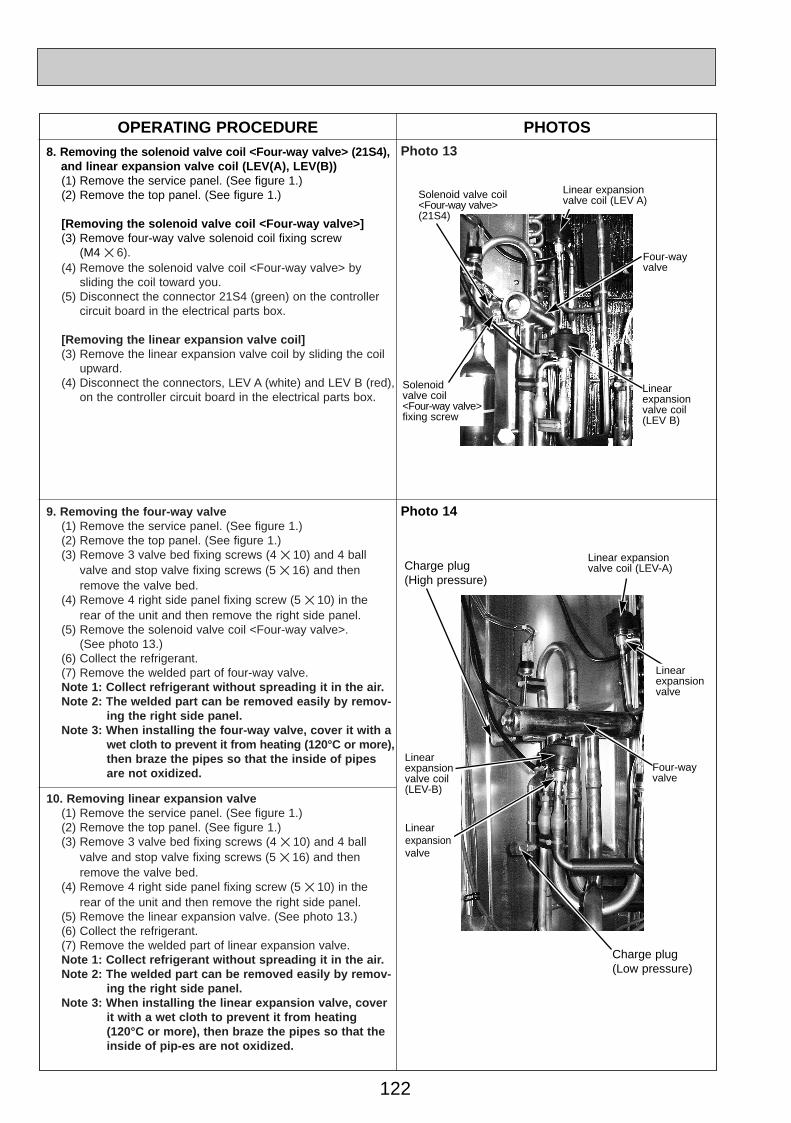
OPERATING PROCEDURE PHOTOS8. Removing the solenoid valve coil <Four-way valve> (21S4),
and linear expansion valve coil (LEV(A), LEV(B))(1) Remove the service panel. (See figure 1.)(2) Remove the top panel. (See figure 1.)
[Removing the solenoid valve coil <Four-way valve>](3) Remove four-way valve solenoid coil fixing screw
(M4 ✕ 6).(4) Remove the solenoid valve coil <Four-way valve> by
sliding the coil toward you.(5) Disconnect the connector 21S4 (green) on the controller
circuit board in the electrical parts box.
[Removing the linear expansion valve coil](3) Remove the linear expansion valve coil by sliding the coil
upward.(4) Disconnect the connectors, LEV A (white) and LEV B (red),
on the controller circuit board in the electrical parts box.
9. Removing the four-way valve(1) Remove the service panel. (See figure 1.)(2) Remove the top panel. (See figure 1.)(3) Remove 3 valve bed fixing screws (4 ✕ 10) and 4 ball
valve and stop valve fixing screws (5 ✕ 16) and then remove the valve bed.
(4) Remove 4 right side panel fixing screw (5 ✕ 10) in the rear of the unit and then remove the right side panel.
(5) Remove the solenoid valve coil <Four-way valve>. (See photo 13.)
(6) Collect the refrigerant.(7) Remove the welded part of four-way valve.Note 1: Collect refrigerant without spreading it in the air.Note 2: The welded part can be removed easily by remov-
ing the right side panel.Note 3: When installing the four-way valve, cover it with a
wet cloth to prevent it from heating (120°C or more), then braze the pipes so that the inside of pipesare not oxidized.
10. Removing linear expansion valve(1) Remove the service panel. (See figure 1.)(2) Remove the top panel. (See figure 1.)(3) Remove 3 valve bed fixing screws (4 ✕ 10) and 4 ball
valve and stop valve fixing screws (5 ✕ 16) and then remove the valve bed.
(4) Remove 4 right side panel fixing screw (5 ✕ 10) in the rear of the unit and then remove the right side panel.
(5) Remove the linear expansion valve. (See photo 13.)(6) Collect the refrigerant.(7) Remove the welded part of linear expansion valve.Note 1: Collect refrigerant without spreading it in the air.Note 2: The welded part can be removed easily by remov-
ing the right side panel.Note 3: When installing the linear expansion valve, cover
it with a wet cloth to prevent it from heating(120°C or more), then braze the pipes so that theinside of pip-es are not oxidized.
Photo 13
Photo 14
Four-wayvalve
Linear expansion valve coil (LEV A)
Linear expansion valve coil (LEV-B)
Linear expansion valve coil (LEV-A)
Four-way valve
Linear expansion valve
Linear expansion valve coil (LEV B)
Linear expansion valve
Solenoid valve coil<Four-way valve> fixing screw
Charge plug(High pressure)
Charge plug(Low pressure)
OC334A-5.qxp 05.12.14 1:14 PM Page 122
123
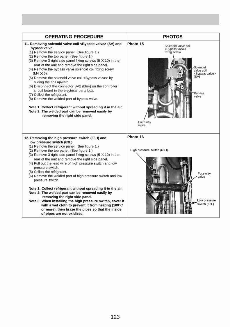
OPERATING PROCEDURE PHOTOS11. Removing solenoid valve coil <Bypass valve> (SV) and
bypass valve(1) Remove the service panel. (See figure 1.)(2) Remove the top panel. (See figure 1.)(3) Remove 3 right side panel fixing screws (5 ✕ 10) in the
rear of the unit and remove the right side panel.(4) Remove the bypass valve solenoid coil fixing screw
(M4 ✕ 6).(5) Remove the solenoid valve coil <Bypass valve> by
sliding the coil upward.(6) Disconnect the connector SV2 (blue) on the controller
circuit board in the electrical parts box.(7) Collect the refrigerant.(8) Remove the welded part of bypass valve.
Note 1: Collect refrigerant without spreading it in the air.Note 2: The welded part can be removed easily by
removing the right side panel.
Photo 15
12. Removing the high pressure switch (63H) and low pressure switch (63L)(1) Remove the service panel. (See figure 1.)(2) Remove the top panel. (See figure 1.)(3) Remove 3 right side panel fixing screws (5 ✕ 10) in the
rear of the unit and remove the right side panel.(4) Pull out the lead wire of high pressure switch and low
pressure switch.(5) Collect the refrigerant.(6) Remove the welded part of high pressure switch and low
pressure switch.
Note 1: Collect refrigerant without spreading it in the air.Note 2: The welded part can be removed easily by
removing the right side panel.Note 3: When installing the high pressure switch, cover it
with a wet cloth to prevent it from heating (100°C or more), then braze the pipes so that the inside of pipes are not oxidized.
Bypass valve
High pressure switch (63H)
Photo 16
Four-way valve
Solenoid valve coil <Bypass valve> fixing screw
Solenoid valve coil <Bypass valve> (SV)
Low pressure switch (63L)
Four-way valve
OC334A-5.qxp 05.12.14 1:14 PM Page 123

124
13. Removing the reactors (ACL1, ACL2, ACL3)(1) Remove the service panel. (See figure 1.)(2) Remove the top panel. (See figure 1.)(3) Remove the 6 screws, screw 8 and 9 (5 ✕ 10), that fix
the front panel and remove the front panel. (See photo 3.)(4) Remove the 2 screws, screw 0 and 1 (both 4 ✕ 10),
that fix the separator, screw 0 from the valve bed and screw 1 from the bottom of the separator, and tilt the separator to the side of the fan motor slightly.(See photo 17.)
(5) Disconnect the lead wires from the reactor and remove the 4 screws, screw 2, that fix the reactor to remove the reactor. (See photo 18 and 19.)
Note 1: The reactor is very heavy (4kg)! Be careful when handling it.
Note 2: The reactor box is also removable.
OPERATING PROCEDURE PHOTOS
Photo 17 Electrical parts box
Screw0
Valve bed
Screw1SeparatorReactor box
Photo 18
Reactors
Reactor box
Electrical parts box
Four-wayvalve
Photo 19
Screw2
Reactor box
Propeller
OC334A-5.qxp 05.12.14 1:14 PM Page 124
125
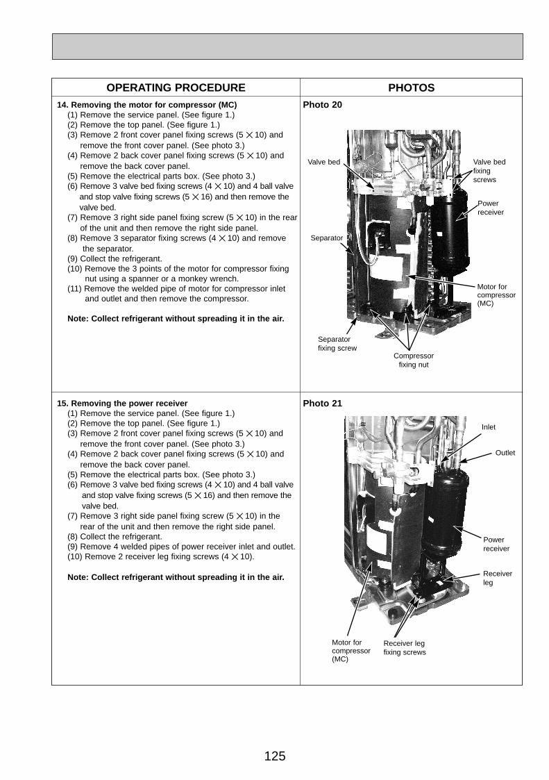
OPERATING PROCEDURE PHOTOS14. Removing the motor for compressor (MC)
(1) Remove the service panel. (See figure 1.)(2) Remove the top panel. (See figure 1.)(3) Remove 2 front cover panel fixing screws (5 ✕ 10) and
remove the front cover panel. (See photo 3.)(4) Remove 2 back cover panel fixing screws (5 ✕ 10) and
remove the back cover panel.(5) Remove the electrical parts box. (See photo 3.)(6) Remove 3 valve bed fixing screws (4 ✕ 10) and 4 ball valve
and stop valve fixing screws (5 ✕ 16) and then remove the valve bed.
(7) Remove 3 right side panel fixing screw (5 ✕ 10) in the rearof the unit and then remove the right side panel.
(8) Remove 3 separator fixing screws (4 ✕ 10) and remove the separator.
(9) Collect the refrigerant.(10) Remove the 3 points of the motor for compressor fixing
nut using a spanner or a monkey wrench.(11) Remove the welded pipe of motor for compressor inlet
and outlet and then remove the compressor.
Note: Collect refrigerant without spreading it in the air.
Photo 20
Motor forcompressor(MC)
Valve bed
Separator
Separatorfixing screw
Powerreceiver
Valve bedfixingscrews
Compressorfixing nut
15. Removing the power receiver (1) Remove the service panel. (See figure 1.)(2) Remove the top panel. (See figure 1.)(3) Remove 2 front cover panel fixing screws (5 ✕ 10) and
remove the front cover panel. (See photo 3.)(4) Remove 2 back cover panel fixing screws (5 ✕ 10) and
remove the back cover panel.(5) Remove the electrical parts box. (See photo 3.)(6) Remove 3 valve bed fixing screws (4 ✕ 10) and 4 ball valve
and stop valve fixing screws (5 ✕ 16) and then remove the valve bed.
(7) Remove 3 right side panel fixing screw (5 ✕ 10) in the rear of the unit and then remove the right side panel.
(8) Collect the refrigerant.(9) Remove 4 welded pipes of power receiver inlet and outlet.(10) Remove 2 receiver leg fixing screws (4 ✕ 10).
Note: Collect refrigerant without spreading it in the air.
Photo 21
Receiver leg fixing screws
Powerreceiver
Receiverleg
Inlet
Outlet
Motor forcompressor(MC)
OC334A-5.qxp 05.12.14 1:14 PM Page 125

126
FUNCTIONAL PARTSPUHZ-RP35/ 50VHAPUHZ-RP50VHA1
1
3
4
2
5 6 7 8
9
10
11
12
13
14
17
15
16
18
19
20212223
24252627
16 PARTS LIST
OC334A-5.qxp 05.12.14 1:14 PM Page 126

127
PricePart No. Part Name SpecificationNo.
WiningDiagramSymbol
Recom-mended
Q,ty Unit Amount
Remarks(Drawing No.)
Q,ty/set
50VHA1
1
2
3
4
5
6
7
8
9
10
11
12
13
14
15
16
17
18
19
20
21
22
23
24
25
26
27
28
MF1
MC
TH4
TH3
21S4
21S4
LEV(A)
63H
63H
LEV(B)
TH6,7
ACL
TB1
N.F.
N.F.
C.B.
C.B.
P.B.
P.B.
TH8
F1,2,3,4
F1,2,3,4
R01 E40 221
R01 E02 115
R01 E04 097
R01 E09 467
T97 420 210
R01 E03 201
R01 E15 440
R01 30L 450
R01 E08 410
R01 E11 410
R01 E08 411
R01 E56 202
T7W E11 242
T7W E16 242
R01 E39 401
R01 E16 242
R01 E10 413
T7W E02 208
R01 E04 208
R01 E08 403
R01 E17 242
R01 E69 202
R01 E06 259
T7W E21 716
T7W E05 346
T7W E11 346
T7W E28 315
T7W E38 315
T7W E17 313
T7W E19 313
R01 E65 202
—
R01 E48 408
T7W 520 239
R01 E02 239
FAN MOTOR
PROPELLER FAN
NUT
MUFFLER
MOTOR FOR COMPRESSOR
THERMISTOR (DISCHARGE)
POWER RECEIVER
STRAINER
STOP VALVE (GAS)
STOP VALVE (GAS)
STOP VALVE (LQUID)
THERMISTOR (OUTDOOR PIPE)
SOLENOID VALVE COIL (FOUR-WAY VALVE)
SOLENOID VALVE COIL (FOUR-WAY VALVE)
EXPANSION VALVE
LINEAR EXPANSION VALVE COIL
CHARGE PLUG
HIGH PRESSURE SWITCH
HIGH PRESSURE SWITCH
FOUR-WAY VALVE
LINEAR EXPANSION VALVE COIL
THERMISTOR (OUTDOOR 2-PHASE PIPE, OUTDOOR)
REACTOR
TERMINAL BLOCK
NOISE FILTER
NOISE FILTER
CONTROLLER CIRCUIT BOARD
CONTROLLER CIRCUIT BOARD
POWER CIRCUIT BOARD
POWER CIRCUIT BOARD
THERMISTOR (HEAT SINK)
ELECTRICAL PARTS BOX
HEAT EXCHANGER
FUSE
FUSE
1
1
1
1
1
1
1
1
1
1
1
1
2
1
1
1
1
1
1
1
1
1
1
1
1
1
1
4
SNB130FLBHIncluding RUBBER MOUNT
1/2
1/2
1/4
6P(L,N,;,S1,S2,S3)
250V 6.3A
250V 6.3A
(RG00N040G12)
PUHZ-RP35/50VHA
1
1
1
1
1
1
1
1
1
1
1
1
2
1
1
1
1
1
1
1
1
1
1
1
1
1
1
4
Part numbers that is circled is not shown in the figure.
OC334A-5.qxp 05.12.14 1:14 PM Page 127
128
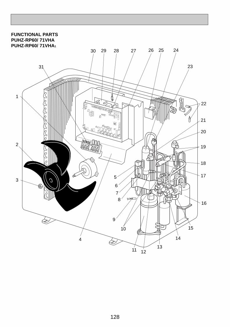
FUNCTIONAL PARTSPUHZ-RP60/ 71VHAPUHZ-RP60/ 71VHA1
16
15
14
1
3
21
22
23
2429 2528 2627
4
9
10
5
12
2
20
13
6
78
11
17
18
19
30
31
OC334A-5.qxp 05.12.14 1:14 PM Page 128
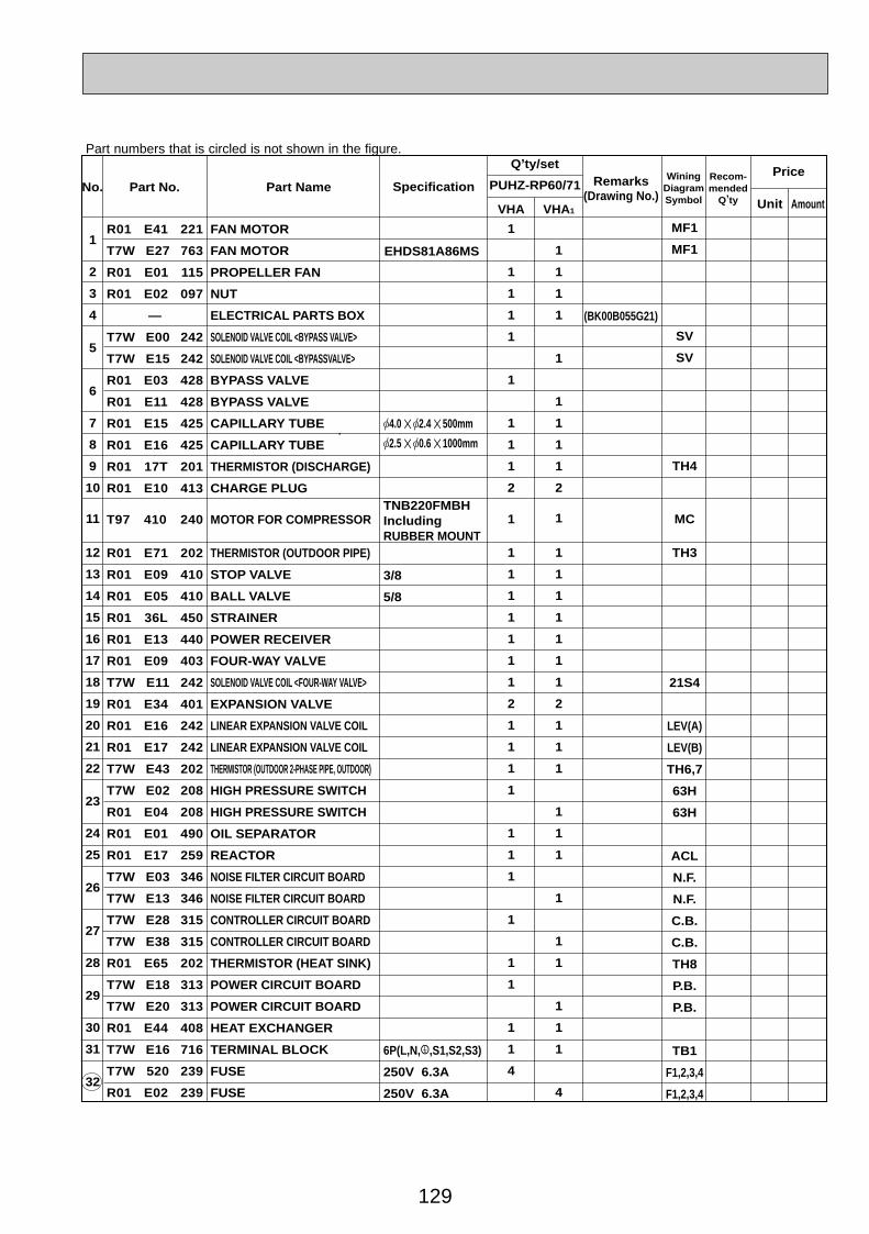
129
PricePart No. Part Name SpecificationNo.
WiningDiagramSymbol
Recom-mended
Q,ty Unit Amount
Remarks(Drawing No.)
Q,ty/set
PUHZ-RP60/71
VHA VHA1
1
2
3
4
5
6
7
8
9
10
11
12
13
14
15
16
17
18
19
20
21
22
23
24
25
26
27
28
29
30
31
32
MF1
MF1
SV
SV
TH4
MC
TH3
21S4
LEV(A)
LEV(B)
TH6,7
63H
63H
ACL
N.F.
N.F.
C.B.
C.B.
TH8
P.B.
P.B.
TB1
F1,2,3,4
F1,2,3,4
R01 E41 221
T7W E27 763
R01 E01 115
R01 E02 097
—
T7W E00 242
T7W E15 242
R01 E03 428
R01 E11 428
R01 E15 425
R01 E16 425
R01 17T 201
R01 E10 413
T97 410 240
R01 E71 202
R01 E09 410
R01 E05 410
R01 36L 450
R01 E13 440
R01 E09 403
T7W E11 242
R01 E34 401
R01 E16 242
R01 E17 242
T7W E43 202
T7W E02 208
R01 E04 208
R01 E01 490
R01 E17 259
T7W E03 346
T7W E13 346
T7W E28 315
T7W E38 315
R01 E65 202
T7W E18 313
T7W E20 313
R01 E44 408
T7W E16 716
T7W 520 239
R01 E02 239
FAN MOTOR
FAN MOTOR
PROPELLER FAN
NUT
ELECTRICAL PARTS BOX
SOLENOID VALVE COIL <BYPASS VALVE>
SOLENOID VALVE COIL <BYPASSVALVE>
BYPASS VALVE
BYPASS VALVE
CAPILLARY TUBE
CAPILLARY TUBE
THERMISTOR (DISCHARGE)
CHARGE PLUG
MOTOR FOR COMPRESSOR
THERMISTOR (OUTDOOR PIPE)
STOP VALVE
BALL VALVE
STRAINER
POWER RECEIVER
FOUR-WAY VALVE
SOLENOID VALVE COIL <FOUR-WAY VALVE>
EXPANSION VALVE
LINEAR EXPANSION VALVE COIL
LINEAR EXPANSION VALVE COIL
THERMISTOR (OUTDOOR 2-PHASE PIPE, OUTDOOR)
HIGH PRESSURE SWITCH
HIGH PRESSURE SWITCH
OIL SEPARATOR
REACTOR
NOISE FILTER CIRCUIT BOARD
NOISE FILTER CIRCUIT BOARD
CONTROLLER CIRCUIT BOARD
CONTROLLER CIRCUIT BOARD
THERMISTOR (HEAT SINK)
POWER CIRCUIT BOARD
POWER CIRCUIT BOARD
HEAT EXCHANGER
TERMINAL BLOCK
FUSE
FUSE
1
1
1
1
1
1
1
1
1
2
1
1
1
1
1
1
1
1
2
1
1
1
1
1
1
1
1
1
1
1
1
4
1
1
1
1
1
1
1
1
1
2
1
1
1
1
1
1
1
1
2
1
1
1
1
1
1
1
1
1
1
1
1
4
[4.0 ✕ [2.4 ✕ 500mm
[2.5 ✕ [0.6 ✕ 1000mm
TNB220FMBHIncluding RUBBER MOUNT
3/8
5/8
6P(L,N,;,S1,S2,S3)
250V 6.3A
250V 6.3A
(BK00B055G21)
EHDS81A86MS
Part numbers that is circled is not shown in the figure.
OC334A-5.qxp 05.12.14 1:14 PM Page 129
130
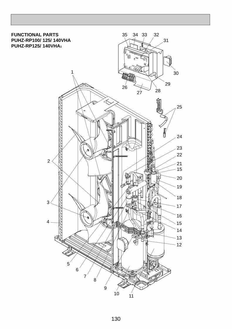
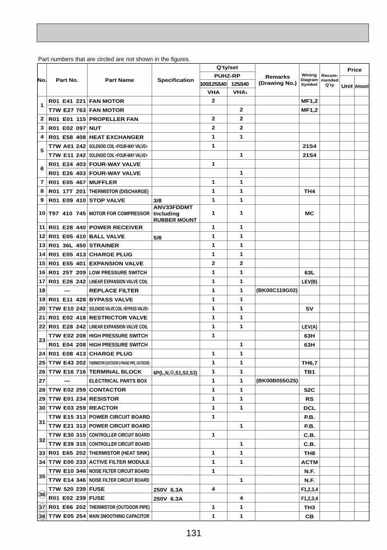
FUNCTIONAL PARTSPUHZ-RP100/ 125/ 140VHAPUHZ-RP125/ 140VHA1
12
3
56
10
2
9
1
4
78
11
13
14
15
16
17
18
19
20
1521
2223
24
25
2627 28
29
30
3132333435
OC334A-5.qxp 05.12.14 1:14 PM Page 130
131
Part No. Part Name SpecificationNo.WiningDiagramSymbol
Recom-mended
Q,ty Unit Amount
Remarks(Drawing No.)
Q,ty/set
100/125/140
VHA
1
2
3
4
5
6
7
8
9
10
11
12
13
14
15
16
17
18
19
20
21
22
23
24
25
26
27
28
29
30
31
32
33
34
35
36
37
38
2
2
2
1
1
1
1
1
1
1
1
1
1
1
2
1
1
1
1
1
1
1
1
1
1
1
1
1
1
1
1
1
1
1
1
4
1
1
2
2
2
1
1
1
1
1
1
1
1
1
1
1
2
1
1
1
1
1
1
1
1
1
1
1
1
1
1
1
1
1
1
1
1
4
1
1
(BK00C119G02)
(BK00B055G25)
R01 E41 221
T7W E27 763
R01 E01 115
R01 E02 097
R01 E58 408
T7W A01 242
T7W E11 242
R01 E24 403
R01 E26 403
R01 E05 467
R01 17T 201
R01 E09 410
T97 410 745
R01 E28 440
R01 E05 410
R01 36L 450
R01 E05 413
R01 E55 401
R01 25T 209
R01 E26 242
—
R01 E11 428
T7W E10 242
R01 E02 418
R01 E28 242
T7W E02 208
R01 E04 208
R01 E08 413
T7W E43 202
T7W E16 716
—
T7W E02 259
T7W E01 234
T7W E03 259
T7W E15 313
T7W E21 313
T7W E30 315
T7W E39 315
R01 E65 202
T7W E00 233
T7W E10 346
T7W E14 346
T7W 520 239
R01 E02 239
R01 E66 202
T7W E05 254
FAN MOTOR
FAN MOTOR
PROPELLER FAN
NUT
HEAT EXCHANGER
SOLENOID COIL <FOUR-WAY VALVE>
SOLENOID COIL <FOUR-WAY VALVE>
FOUR-WAY VALVE
FOUR-WAY VALVE
MUFFLER
THERMISTOR (DISCHARGE)
STOP VALVE
MOTOR FOR COMPRESSOR
POWER RECEIVER
BALL VALVE
STRAINER
CHARGE PLUG
EXPANSION VALVE
LOW PRESSURE SWITCH
LINEAR EXPANSION VALVE COIL
REPLACE FILTER
BYPASS VALVE
SOLENOID VALVE COIL <BYPASS VALVE>
RESTRICTOR VALVE
LINEAR EXPANSION VALVE COIL
HIGH PRESSURE SWITCH
HIGH PRESSURE SWITCH
CHARGE PLUG
THERMISTOR (OUTDOOR 2-PHASE PIPE, OUTDOOR)
TERMINAL BLOCK
ELECTRICAL PARTS BOX
CONTACTOR
RESISTOR
REACTOR
POWER CIRCUIT BOARD
POWER CIRCUIT BOARD
CONTROLLER CIRCUIT BOARD
CONTROLLER CIRCUIT BOARD
THERMISTOR (HEAT SINK)
ACTIVE FILTER MODULE
NOISE FILTER CIRCUIT BOARD
NOISE FILTER CIRCUIT BOARD
FUSE
FUSE
THERMISTOR (OUTDOOR PIPE)
MAIN SMOOTHING CAPACITOR
PUHZ-RPPrice
MF1,2
MF1,2
21S4
21S4
TH4
MC
63L
LEV(B)
SV
LEV(A)
63H
63H
TH6,7
TB1
52C
RS
DCL
P.B.
P.B.
C.B.
C.B.
TH8
ACTM
N.F.
N.F.
F1,2,3,4
F1,2,3,4
TH3
CB
3/8ANV33FDDMTIncluding RUBBER MOUNT
5/8
6P(L,N,;,S1,S2,S3)
250V 6.3A
250V 6.3A
125/140
VHA1
Part numbers that are circled are not shown in the figures.
OC334A-5.qxp 05.12.14 1:14 PM Page 131
132
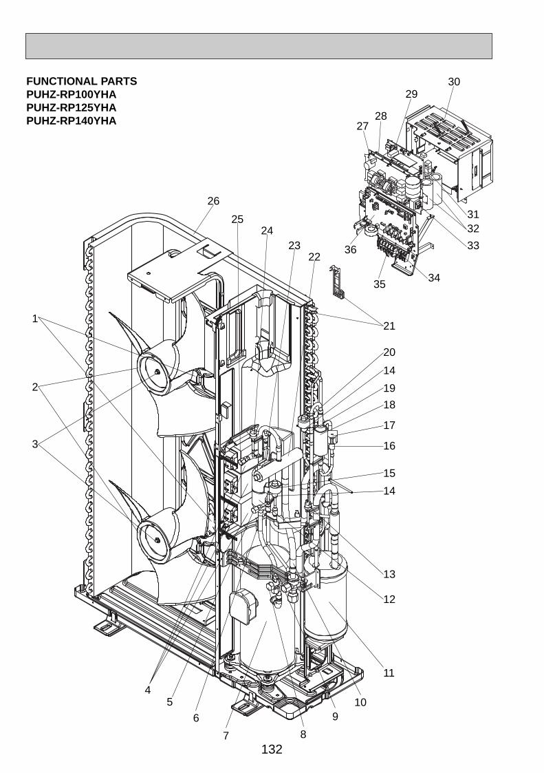
FUNCTIONAL PARTSPUHZ-RP100YHAPUHZ-RP125YHAPUHZ-RP140YHA
1
2
3
2423
22
21
25
26
45
6
7 8
910
11
12
13
14
15
16
17
18
14
20
19
27
2930
3132
33
3435
36
28
OC334A-5.qxp 05.12.14 1:14 PM Page 132

133
Part No. Part Name SpecificationNo.WiningDiagramSymbol
Recom-mended
Q,ty Unit Amount
Remarks(Drawing No.)
Q,ty/set
100 125
YHA
1
2
3
4
5
6
7
8
9
10
11
12
13
14
15
16
17
18
19
20
21
22
23
24
25
26
27
28
29
30
31
32
33
34
35
36
37
38
39
2
2
2
3
1
1
1
1
1
1
1
1
1
2
1
1
1
1
1
1
1
1
1
1
1
1
1
1
1
1
1
2
1
1
1
1
4
1
1
2
2
2
3
1
1
1
1
1
1
1
1
1
2
1
1
1
1
1
1
1
1
1
1
1
1
1
1
1
1
1
2
1
1
1
1
4
1
1
2
2
2
3
1
1
1
1
1
1
1
1
1
2
1
1
1
1
1
1
1
1
1
1
1
1
1
1
1
1
1
2
1
1
1
1
4
1
1
140
(BK00C119G02)
(BK00C410G04)
R01 E41 221
R01 E01 115
R01 E02 097
T7W E07 259
R01 E05 413
R01 A19 201
T97 410 743
R01 E09 410
R01 E05 410
R01 36L 450
R01 E28 440
R01 E05 467
R01 25T 209
R01 E55 401
R01 E26 242
R01 E11 428
T7W E10 242
—
R01 E02 418
T7W E09 242
R01 E75 202
R01 E24 403
T7W A01 242
T7W E02 208
R01 E08 413
R01 E58 408
T7W E08 346
T7W E39 310
T7W E13 313
—
R01 E08 233
T7W E03 254
T7W E06 259
T7W E22 716
T7W E06 716
T7W E29 315
R01 E02 239
R01 E66 202
T7W E06 254
FAN MOTOR
PROPELLER
NUT
REACTOR
CHARGE PLUG
THERMISTOR (DISCHARGE)
MOTOR FOR COMPRESSOR
STOP VALVE
BALL VALVE
STRAINER
POWER RECEIVER
MUFFLER
LOW PRESSURE SWITCH
EXPANSION VALVE
LINEAR EXPANSION VALVE COIL
BYPASS VALVE
SOLENOID VALVE COIL <BYPASS VALVE>
REPLACE FILTER
RESTRICTOR VALVE
LINEAR EXPANSION VALVE COIL
THERMISTOR (OUTDOOR 2-PHASE PIPE, OUTDOOR)
FOUR-WAY VALVE
SOLENOID COIL <FOUR-WAY VALVE>
HIGH PRESSURE SWITCH
CHARGE PLUG
HEAT EXCHANGER
NOISE FILTER CIRCUIT BOARD
CONVERTER CIRCUIT BOARD
POWER CIRCUIT BOARD
ELECTRICAL PARTS BOX
RESISTOR
MAIN SMOOTHING CAPACITOR
REACTOR
TERMINAL BLOCK
TERMINAL BLOCK
CONTROLLER CIRCUIT BOARD
FUSE
THERMISTOR (OUTDOOR PIPE)
CAPACITOR
PUHZ-RPPrice
MF1,2
ACL1,2,3
TH4
MC
63L
LEV(B)
SV
LEV(A)
TH6,7
21S4
63H
N.F.
CONV.B.
P.B.
RS
CB1, CB2
ACL4
TB2
TB1
C.B.
F1,2,3,4
TH3
CK
ANV33FDBMTIncluding RUBBER MOUNT
3/8
5/8
3P (S1,S2,S3)
5P (L1,L2,L3,N,;)
250V 6.3A
Part numbers that are circled are not shown in the figures.
OC334A-5.qxp 05.12.14 1:14 PM Page 133

134
STRUCTURAL PARTSPUHZ-RP35/ 50VHAPUHZ-RP50VHA1
Part No. SpecificationNo.Wining
DiagramSymbol
Recom-mended
Q,ty
Price
Unit AmountPart Name
Q,ty/set
PUHZ-RP35/50VHAPUHZ-RP50VHA1
Remarks(Drawing No.)
1
2
3
4
5
6
7
8
9
10
11
12
13
1
1
1
1
1
1
1
1
1
1
1
1
12(4✕10)
R01 E10 691
R01 E02 668
R01 E15 686
—
R01 E02 667
R01 E00 518
R01 E02 682
R01 E21 130
R01 E01 684
T7W E01 641
—
—
—
GRILLE
FRONT PANEL
BASE ASSY
SEPARATOR
SERVICE PANEL
SERVICE PANEL
BACK PANEL
MOTOR SUPPORT
CONDENSER NET
TOP PANEL
LABEL (MITSUBISHI)
LABEL (INVERTER)
F.ST SCREW
(SU00B229G35)
(DG79R130H01)
(BK79C208G02)
(Z504K189H37)
1 2 3 4 5
67
8
9
10
1112
13
OC334A-5.qxp 05.12.14 1:14 PM Page 134

135
STRUCTURAL PARTSPUHZ-RP60/ 71VHAPUHZ-RP60/ 71VHA1
Part No. SpecificationNo.Wining
DiagramSymbol
Recom-mended
Q,ty
Price
Unit AmountPart Name PUHZ-RP
Q,ty/set
60/ 71VHA
Remarks(Drawing No.)
1
2
3
4
5
6
7
8
9
10
11
12
13
14
15
16
17
18
31
1
1
1
1
1
1
1
2
1
1
1
1
1
1
1
1
1
(5✕10)—
R01 E01 662
T7W E02 691
T7W E01 667
—
R01 E13 686
R01 E06 130
—
R01 30L 655
R01 E02 658
R01 E01 658
R01 E05 658
R01 E03 661
T7W E02 668
—
—
R01 E00 698
R01 E04 641
R01 E00 655
F.ST SCREW
SIDE PANEL (L)
FAN GRILLE
FRONT PANEL
SEPARATOR
BASE ASSY
MOTOR SUPPORT
VALVE BED ASSY
HANDLE
COVER PANEL (FRONT)
COVER PANEL (REAR)
COVER PANEL (REAR)
SIDE PANEL (R)
SERVICE PANEL
LABEL (MITSUBISHI)
LABEL (INVERTER)
REAR GUARD
TOP PANEL
HANDLE
(DG12F536H10)
(BK00C143G71)
(BK00C142G16)
(DG79R130H01)
(BK79C208G02)
VHA1
31
1
1
1
1
1
1
1
2
1
1
1
1
1
1
1
1
1
1
152
4
5
9 11
1412
13
3
6 78
10
9
17
1816
OC334A-5.qxp 05.12.14 1:14 PM Page 135
136
Part No. Part Name SpecificatioNo.Wining
DiagramSymbol
Recom-mended
Q,ty
Q,ty/setPUHZ-RP
VHA YHA100/ 125/ 140
1
2
3
4
5
6
7
8
9
10
11
12
13
14
15
16
17
18
38
1
2
1
1
1
1
1
2
1
1
1
1
1
1
1
1
1
38
1
2
1
1
1
1
1
2
1
1
1
1
1
1
1
1
1
(DG12F536H10)
VHA (BK00C143G78)
YHA (BK00C409G03)
(BK00C142G16)
(DG79R130H01)
(BK79C208G02)
F.ST SCREW
SIDE PANEL (L)
FAN GRILLE
FRONT PANEL
SEPARATOR
BASE ASSY
MOTOR SUPPORT
VALVE BED ASSY
HANDLE
COVER PANEL (FRONT)
COVER PANEL (FRONT)
COVER PANEL (REAR)
COVER PANEL (REAR)
SIDE PANEL (R)
SERVICE PANEL
SERVICE PANEL
LABEL (MITSUBISHI)
LABEL (INVERTER)
REAR GUARD
TOP PANEL
TOP PANEL
HANDLE
(5✕10)
AmountUnit
PriceRemarks
(Drawing No.)
—
R01 E02 662
T7W E02 691
T7W E02 667
—
R01 E14 686
R01 E25 130
—
R01 30L 655
R01 E00 658
R01 E04 658
R01 E01 658
R01 E05 658
T7W E15 661
T7W E03 668
T7W E04 668
—
—
R01 E01 698
R01 E04 641
R01 E08 641
R01 E00 655
125/140VHA1
38
1
2
1
1
1
1
1
2
1
1
1
1
1
1
1
1
1
1
15
2
4
59
11
1412
13
6 78
10
9
17
18
3
16
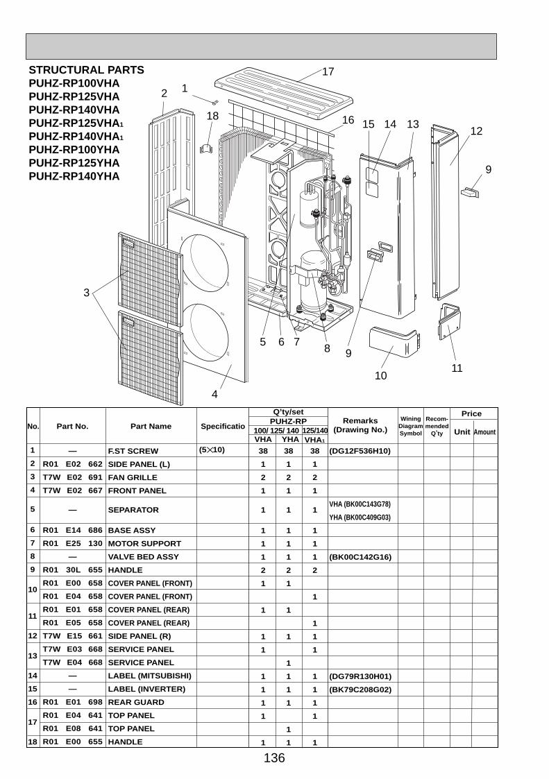
STRUCTURAL PARTSPUHZ-RP100VHAPUHZ-RP125VHAPUHZ-RP140VHAPUHZ-RP125VHA1
PUHZ-RP140VHA1
PUHZ-RP100YHAPUHZ-RP125YHAPUHZ-RP140YHA
OC334A-5.qxp 05.12.14 1:14 PM Page 136

137
OC334A-5.qxp 05.12.14 1:14 PM Page 137

HEAD OFFICE : TOKYO BLDG., 2-7-3, MARUNOUCHI, CHIYODA-KU, TOKYO 100-8310, JAPAN
CCopyright 2005 MITSUBISHI ELECTRIC ENGINEERING CO., LTD.Distributed in Dec. 2005 No.OC334 REVISED EDITION-A PDF 9Distributed in Jun. 2005 No.OC334 PDF 9Made in Japan.
New publication, effective Dec. 2005.Specifications subject to change without notice.
TM
OC334A-5.qxp 05.12.14 1:14 PM Page 138


![[Service Ref.] PUHZ-SHW80VHA - ecodanshop.huecodanshop.hu/images/dokumentumok/ZUBADAN%20PUHZ-SHW80V… · name plate. PARTS CATALOG (OCB526) Outdoor unit [Model names] PUHZ-SHW80VHA](https://img.pdfslide.us/doc/110x75/5a9c4c9c7f8b9adb5c8e43cb/service-ref-puhz-shw80vha-20puhz-shw80vname-plate-parts-catalog-ocb526.jpg)
![SERVICE MANUAL - mitsubishi-les.info€¦ · April 2007 Outdoor unit [model names] PUHZ-P100VHA2 PUHZ-P125VHA2 PUHZ-P140VHA2 [Service Ref.] PUHZ-P100VHA2.UK PUHZ-P125VHA2.UK PUHZ-P140VHA2.UK](https://img.pdfslide.us/doc/110x75/5fb7bf44cae4eb7f0b7b27ec/service-manual-mitsubishi-lesinfo-april-2007-outdoor-unit-model-names-puhz-p100vha2.jpg)


![No.OCH544 SERVICE MANUAL - Mitsubishi Electric...SERVICE MANUAL No.OCH544 SPLIT-TYPE, HEAT PUMP AIR CONDITIONERS R410A August 2013 Outdoor unit [Model name] PUHZ-FRP71VHA [Service](https://img.pdfslide.us/doc/110x75/5e5c9ecb79415e016c776870/nooch544-service-manual-mitsubishi-electric-service-manual-nooch544-split-type.jpg)

![Outdoor unit [Model Name] [Service Ref.] PUHZ-W112VHA PUHZ](https://img.pdfslide.us/doc/110x75/625f81d8e8d5824f0710d723/outdoor-unit-model-name-service-ref-puhz-w112vha-puhz-.jpg)


![SPLIT-TYPE, HEAT PUMP AIR CONDITIONERS · PDF filesplit-type, heat pump air conditioners outdoor unit [model names] puhz-sp100vha puhz-sp125vha puhz-sp140vha ... 14 g s70 e10 699label](https://img.pdfslide.us/doc/110x75/5a9e41fc7f8b9aee4a8bfd4d/split-type-heat-pump-air-conditioners-heat-pump-air-conditioners-outdoor-unit-model.jpg)