Embed Size (px)
Citation preview

A300-600A300-600SERVICE BULLETIN
REVISION TRANSMITTAL SHEET
AIRBUSCUSTOMER SERVICES DIRECTORATE1 Rond Point Maurice Bellonte31707 BLAGNAC CEDEX FRANCETel : (33) 5 61 93 33 33Telex : AIRBU 530526FFax : (33) 5 61 93 42 51
MANDATORY MANDATORY MANDATORY MANDATORY
ATA SYSTEM : 28
TITLE : FUEL - GENERAL - MODIFY THE EQUIPMENT IN THE FUEL TANKS FOR ADDITIONALELECTRICAL BONDING
MODIFICATION No. : 12495H5555
This page transmits Revision No. 05 of Service Bulletin No. A300-28-6064
ADDITIONAL WORK
No additional work is required by this revision for aircraft modified by any previous issue.
REASON
Revision 05 has been issued to inform operators that:
- The test reference has been clarified for connectors 1076VC and 2022VC.
- An option to install a second washer at certain locations has been added.
- CB’s have been clarified for Config. 07.
- Installation of the bonding leads on the refueling pipes on LH side between FR44 and FR47 isupdated for Kit A01 and Kit A02
- Installation of the bonding leads on the TTS pipes is updated for Kit A01 and Kit A02.
- Procedure for removal of rivets is included.
- Figure 4, Sheets 1 and 14 thru 16 have been revised to clarify bonding.
- Figure 8, Sheet 2 has been revised to clarify bonding.
- Figure 12, Sheets 3 and 6 thru 8 have been revised to clarify bonding.
- Figure 14, Sheet 2 and 3 have been revised to clarify bonding.
- Figure 15, Sheet 4 and 5 have been revised to clarify bonding.
- Figure 16, Sheet 3 has been revised to clarify validity.
- Figure 18, Sheet 2 and 3 have been revised to clarify bonding.
DATE : Jul 28/05 SERVICE BULLETIN No. : A300-28-6064
REVISION No. : 05 - Sep 27/10 Page : 1 of 8
Printed in France © AIRBUS 2008 All rights reserved

A300-600A300-600SERVICE BULLETIN
REVISION TRANSMITTAL SHEET
- Figure 19, Sheet 4 and 5 have been revised to clarify bonding.
- Figure 23, Sheet 2 has been revised to remove a bonding lead.
- Figure 33, Sheet 2 and Figure 47, Sheet 2 have been revised to add missing washers.
- Figures 35, 37, 39, 40, 42, 43, 45, 46, 47, 48, 49, 50 and 51 have been revised to correct references.
CHANGES
SUMMARY :
- EFFECTIVITY
. Operators CSN and EGN deleted. Operators 66U, IRM and UZB added.
- MANPOWER
. Introduced by Rev 04 has been added.
PLANNING INFORMATION :
- EFFECTIVITY
. 1.A. Effectivity Updated. Kit/Configurations have been changed from None to ALL.
- DESCRIPTION
. 1.D.(8) Introduced by Rev 04 has been added.
. 1.D.(9) Introduced by Rev 04 has been added.
- COMPLIANCE
- Accomplishment Timescale
. 1.E.(2)(a) Standard sentence has been updated.
- MANPOWER
. 1.G. Introduced by Rev 04 has been added.
- REFERENCES
. 1.J. Reference added.
MATERIAL INFORMATION :
- MATERIAL - PRICE AND AVAILABILITY
- Material
. 2.A.(1) AIRBUS address has been amended.
DATE : Jul 28/05 SERVICE BULLETIN No. : A300-28-6064
REVISION No. : 05 - Sep 27/10 Page : 2
Printed in France © AIRBUS 2008 All rights reserved

A300-600A300-600SERVICE BULLETIN
REVISION TRANSMITTAL SHEET
- LIST OF COMPONENTS
. 2.C. Item 5 in kit A02, quantity changed. PN has changed from E0088-10-160 to E0088-16-200.
. 2.C. Quantity of item 5 changed to 19. PN has changed from E0088-10-160 to E0088-16-200.
. 2.C. PN has been changed from E0088-10-160 to E0088-16-200.
ACCOMPLISHMENT INSTRUCTIONS :
- Preparation
. 3.A.(1) CB title corrected for Config. 07.
. 3.A.(1)(p) Introduced by Rev 04 has been added.
. 3.A.(1)(p)5 CB title corrected.
- MODIFICATION
. 3.B. Washer quantities changed and Notes added. Installation of the bonding leads on therefueling pipes on LH side between FR44 and FR47 updated for Kit A01 and Kit A02. Installationof the bonding leads on the TTS pipes updated for Kit A01 and Kit A02.
. 3.B.(2) Workstep has been removed.
. 3.B.(2)(a)3 Mod. statement added.
. 3.B.(2)(a)4c Workstep has been added.
. 3.B.(3)(a)1c Part numbers updated.
. 3.B.(3)(a)3a Part numbers updated.
. 3.B.(3)(a)3f Part numbers updated.
. 3.B.(5)(a) Introduced at Rev 01 has been added.
. 3.B.(8)(b) Washer quantity changed and Note added.
. 3.B.(8)(b)3 Washer quantity changed and Note added.
. 3.B.(9)(b) Washer quantity changed and Note added.
. 3.B.(9)(b)3 Washer quantity changed and Note added.
. 3.B.(11)(a)6 Figure reference updated.
. 3.B.(11)(b) Washer quantity changed and Note added.
. 3.B.(11)(b)3 Washer quantity changed and Note added.
. 3.B.(13) Item numbers corrected.
DATE : Jul 28/05 SERVICE BULLETIN No. : A300-28-6064
REVISION No. : 05 - Sep 27/10 Page : 3
Printed in France © AIRBUS 2008 All rights reserved

A300-600A300-600SERVICE BULLETIN
REVISION TRANSMITTAL SHEET
. 3.B.(13)(a)4 Item number corrected.
. 3.B.(13)(a)6 New workstep added.
. 3.B.(13)(a)7 Workstep added.
. 3.B.(13)(a)8 Workstep added.
. 3.B.(13)(a)9 Items and quantities changed.
. 3.B.(13)(b) Washer quantity changed and Note added.
. 3.B.(13)(b)3 Washer quantity changed and Note added.
. 3.B.(15)(b) Washer quantity changed and Note added.
. 3.B.(15)(b)3 Washer quantity changed and Note added.
. 3.B.(16) Item numbers corrected.
. 3.B.(16)(a)6 New workstep added.
. 3.B.(16)(a)7 Workstep added.
. 3.B.(16)(a)8 Workstep added.
. 3.B.(16)(a)9 Items and quantities changed.
. 3.B.(16)(b) Washer quantity changed and Note added.
. 3.B.(16)(b)3 Washer quantity changed and Note added.
. 3.B.(19) Item numbers corrected.
. 3.B.(19)(a)6 New workstep added.
. 3.B.(19)(a)7 Workstep added.
. 3.B.(19)(a)8 Workstep added.
. 3.B.(19)(a)9 Item numbers revised.
. 3.B.(19)(b) Washer quantity changed and Note added.
. 3.B.(19)(b)3 Washer quantity changed and Note added.
. 3.B.(20)(b) Washer quantity changed and Note added.
. 3.B.(20)(b)3 Washer quantity changed and Note added.
. 3.B.(21)(b) Washer quantity changed and Note added.
. 3.B.(21)(b)3 Washer quantity changed and Note added.
DATE : Jul 28/05 SERVICE BULLETIN No. : A300-28-6064
REVISION No. : 05 - Sep 27/10 Page : 4
Printed in France © AIRBUS 2008 All rights reserved

A300-600A300-600SERVICE BULLETIN
REVISION TRANSMITTAL SHEET
. 3.B.(22)(b) Washer quantity changed and Note added.
. 3.B.(22)(b)3 Washer quantity changed and Note added.
. 3.B.(24)(b) Washer quantity changed and Note added.
. 3.B.(24)(b)5 Washer quantity changed and Note added.
. 3.B.(25)(b) Washer quantity changed and Note added.
. 3.B.(25)(b)3 Washer quantity changed and Note added.
. 3.B.(29) Introduced by Rev 04 has been added.
. 3.B.(30) Introduced by Rev 04 has been added.
- TESTS
. 3.C. AMM Reference added for test.
. 3.C.(3)(c)4 AMM Reference added.
. 3.C.(5) Introduced by Rev 04 has been added.
. 3.C.(6) Introduced by Rev 04 has been added.
- CLOSE-UP
. 3.D. CB’s corrected for Config. 07.
. 3.D.(5) Introduced by Rev 04 has been added.
. 3.D.(6) Introduced by Rev 04 has been added.
. 3.D.(6)(a) CB’s corrected.
. 3.D.(6)(a)4 CB’s corrected.
- Figure 1
. Figure 1, Sheet 1 updated.
- Figure 4
. Sheets 1 and 14 thru 16 revised.
- Figure 8
. Figure 8, Sheet 2
- Figure 12
. Sheet 3 and 6 thru 8 revised.
DATE : Jul 28/05 SERVICE BULLETIN No. : A300-28-6064
REVISION No. : 05 - Sep 27/10 Page : 5
Printed in France © AIRBUS 2008 All rights reserved

A300-600A300-600SERVICE BULLETIN
REVISION TRANSMITTAL SHEET
- Figure 14
. Sheets 2 and 3 revised.
- Figure 15
. Figure 15, Sheets 4, 5 and 7 modified.
- Figure 16
. Sheet 3 revised.
- Figure 18
. Sheets 2 and 3 revised.
- Figure 19
. Sheets 4 and 5 revised.
- Figure 23
. Sheet 2 revised to remove one bonding lead
- Figure 32
. Figure reference changed.
- Figure 33
. Sheet 2 Revised.
- Figure 34
. Sheet 2 revised.
- Figure 36
. Washer quantity changed.
- Figure 40
. Figure reference changed.
- Figure 42
. Figure reference changed.
- Figure 43
. Figure reference changed.
- Figure 44
DATE : Jul 28/05 SERVICE BULLETIN No. : A300-28-6064
REVISION No. : 05 - Sep 27/10 Page : 6
Printed in France © AIRBUS 2008 All rights reserved

A300-600A300-600SERVICE BULLETIN
REVISION TRANSMITTAL SHEET
. Figure reference changed.
- Figure 45
. Figure reference changed.
- Figure 46
. Figure reference changed.
- Figure 47
. Figure reference changed.
- Figure 48
. Figure reference changed.
- Figure 50
. Sheet 2 revised.
- Figure 51
. Sheet 2 revised.
- Figure 52
. Washer quantity changed.
FILING INSTRUCTIONS
This Service Bulletin has been generated electronically and is reissued as a complete document.Replace the complete document.
Put this Revision Transmittal Sheet in front of the Service Bulletin.
HISTORY OF PREVIOUS REVISIONS
Revision No. 01 was issued to:
- incorporate the comments of an airline request,
- update the effectivity,
- apply refuel/defuel valve modification on the LH wing for all aircraft.
Other minor changes to the new Service Bulletin format were added.
This Service Bulletin has been revised following operator queries on figure references, item numbers,bolt lengths and effectivity applicability.
DATE : Jul 28/05 SERVICE BULLETIN No. : A300-28-6064
REVISION No. : 05 - Sep 27/10 Page : 7
Printed in France © AIRBUS 2008 All rights reserved

A300-600A300-600SERVICE BULLETIN
REVISION TRANSMITTAL SHEET
Revision No. 02 was issued to include improvements further to discrepancies found duringaccomplishment.
Revision No. 03 was issued to include improvements further to discrepancies found duringaccomplishment.
Revision 04 was issued to inform operators that:
- for access reasons, the location of the bonding lead on Figure 44 was changed.
- Kit B26, Qty 4 were necessary for Config. 01.
- Additional Work was added for Config. 07.
- Other additional work was also required by this revision for Config. 03 (using Kit A03).
REVISION SEQUENCE
ORIGINAL : Jul 28/05REVISION No. : 01 - Apr 03/07REVISION No. : 02 - Mar 10/08REVISION No. : 03 - Dec 15/08REVISION No. : 04 - Aug 24/09REVISION No. : 05 - Sep 27/10
DATE : Jul 28/05 SERVICE BULLETIN No. : A300-28-6064
REVISION No. : 05 - Sep 27/10 Page : 8
Printed in France © AIRBUS 2008 All rights reserved

A300-600A300-600SERVICE BULLETIN
SUMMARY
AIRBUSCUSTOMER SERVICES DIRECTORATE1 Rond Point Maurice Bellonte31707 BLAGNAC CEDEX FRANCETel : (33) 5 61 93 33 33Telex : AIRBU 530526FFax : (33) 5 61 93 42 51
This summary is for information only and isnot approved for modification of the aircraft
MANDATORY MANDATORY MANDATORY MANDATORY
ATA SYSTEM : 28
TITLE : FUEL - GENERAL - MODIFY THE EQUIPMENT IN THE FUEL TANKS FOR ADDITIONALELECTRICAL BONDING
MODIFICATION No. : 12495H5555
REASON/DESCRIPTION/OPERATIONAL CONSEQUENCES
As part of the Fuel Safety Assessment program, AIRBUS has carried out investigations of the electricalbonding in the aircraft fuel tanks.
As a result of these investigations this Service Bulletin has been issued for additional electrical bonding of theequipment in the fuel tanks. This modification consists of installing additional bonding leads and electricalbonding points in the wings fuel tanks and center tank.
The accomplishment of this Service Bulletin provides improved electrical bonding to ensure continuouselectrical bonding protection of all the equipment in the fuel tanks for the design life goal of the aircraft.
This Service Bulletin has been validated on A300-600 aircraft MSN 0569.
EVALUATION TABLE
COMPLIANCE Mandatory CANCELS INSPECTION SB No
POTENTIAL AD Yes A/C OPERATION AFFECTED No
RELIABILITY AFFECTED No PAX COMFORT AFFECTED No
COST SAVING No ETOPS AFFECTED No
STRUCTURAL LIFE EXTN No VENDOR SB INVOLVED No
DEFUEL/VENTILATION Yes KIT PRICE (USD) Refer to SB
MODIFICATION CLASSIFICATION
MAJOR None
MINOR 12495H5555
DATE : Jul 28/05 SERVICE BULLETIN No. : A300-28-6064
REVISION No. : 05 - Sep 27/10 Page : 1 of 4
Printed in France © AIRBUS 2008 All rights reserved
A300-600A300-600SERVICE BULLETIN
SUMMARY
As per EASA IR 21, a minor change is one that has no appreciable effect on the mass, balance, structuralstrength, reliability, operational characteristics, affecting the airworthiness of the product. All other changesare Major changes.
EFFECTIVITY
This Service Bulletin is applicable to these operators:
66U AAL AAW ABD AMU CES DLH F2I FDX G8E IRA IRM JAL KAC KAL LAA MNB MON MSR MXUOHY QTR SUD TAR THA UPS UZB
CONCURRENT REQUIREMENTS
None
REFERENCES/REPERCUSSIONS
TFU : None
OEB : None
AOT : None
SIL : 28-072
LIFE LIMIT : None
LINE MAINTENANCE AFFECTED : No
OTHERS : None
NATURE OF THE WORK
AIRCRAFT : Yes
EQUIPMENT : No
HARD : No
SOFT : No
OBRM : No
MANPOWER
Center Tank, Kit 286064A01R05
TOTAL MANHOURS 114.5
ELAPSED TIME (HOURS) 73.0
Center Tank, Kit 286064A02R02
DATE : Jul 28/05 SERVICE BULLETIN No. : A300-28-6064
REVISION No. : 05 - Sep 27/10 Page : 2
Printed in France © AIRBUS 2008 All rights reserved

A300-600A300-600SERVICE BULLETIN
SUMMARY
TOTAL MANHOURS 114.5
ELAPSED TIME (HOURS) 73.0
Center Tank, Kit 286064A03R00
TOTAL MANHOURS 104.5
ELAPSED TIME (HOURS) 63.0
LH and RH Wing Fuel Tanks - Config. 08 (Post Mod. 12226 Aircraft only)
TOTAL MANHOURS 20
ELAPSED TIME (HOURS) 10.0
LH and RH Wing Fuel Tanks - All other Aircraft
TOTAL MANHOURS 226.0*
ELAPSED TIME (HOURS) 114.5
NOTE(*) Subject to aircraft configuration. Refer to para. 1.G. MANPOWER in the Service Bulletin for thebreakdown of the wings manhours. The manhours are given by rib bay and aircraft configuration.
ADDITIONAL WORK (Introduced by Rev 01)
TOTAL MANHOURS 2.0
ELAPSED TIME (HOURS) 2.0
ADDITIONAL WORK (Introduced by Rev 03)
TOTAL MANHOURS 62.5
ELAPSED TIME (HOURS) 31.0
ADDITIONAL WORK (Introduced by Rev 04)
TOTAL MANHOURS 4.0
ELAPSED TIME (HOURS) 2.0
ADDITIONAL WORK (Introduced by Rev 04)
DATE : Jul 28/05 SERVICE BULLETIN No. : A300-28-6064
REVISION No. : 05 - Sep 27/10 Page : 3
Printed in France © AIRBUS 2008 All rights reserved

A300-600A300-600SERVICE BULLETIN
SUMMARY
TOTAL MANHOURS 4.0
ELAPSED TIME (HOURS) 2.0
ADDITIONAL WORK (Introduced by Rev 04)
TOTAL MANHOURS 64.5
ELAPSED TIME (HOURS) 31.0
MATERIAL INFORMATION
AIRCRAFT DATA
Center Tank - Kit 286064A01R05 thru Kit 286064A03R00:
Bonding leads, clamps, rivets, bolts, nuts and washers.
Wings Fuel Tanks Equipment - Kit 286064B01R05 thru Kit 286064B28R01:
Bonding leads, clamps, bolts, nuts, washers and drain attachment plates.
NOTE : Kit 286064B24R01 has not been used.
ADDITIONAL WORK (Introduced by Rev 01)
Wings Fuel Tanks Equipment - Kit 286064B39R00:
Bonding leads, nuts and screws.
APPENDICES
None
DATE : Jul 28/05 SERVICE BULLETIN No. : A300-28-6064
REVISION No. : 05 - Sep 27/10 Page : 4
Printed in France © AIRBUS 2008 All rights reserved

A300-600A300-600SERVICE BULLETIN
AIRBUSCUSTOMER SERVICES DIRECTORATE1 Rond Point Maurice Bellonte31707 BLAGNAC CEDEX FRANCETel : (33) 5 61 93 33 33Telex : AIRBU 530526FFax : (33) 5 61 93 42 51
MANDATORY MANDATORY MANDATORY MANDATORY
ATA SYSTEM : 28
TITLE : FUEL - GENERAL - MODIFY THE EQUIPMENT IN THE FUEL TANKS FOR ADDITIONALELECTRICAL BONDING
MODIFICATION No. : 12495H5555
This document contains AIRBUS PROPRIETARY INFORMATION and shall at all times remain the propertyof AIRBUS; no intellectual property right or license is granted by AIRBUS in connection with any informationcontained in it. It is delivered on the express condition that said document and the information contained init shall be treated as confidential, shall not be used for any purpose other than that for which it is herebydelivered. It shall not be disclosed in whole or part to third parties and shall not be duplicated in any manner(except for the purpose of performing the tasks described hereunder and provided that any recipient of suchdocument shall comply with the conditions herein), without AIRBUS prior written consent.
1. PLANNING INFORMATION
A. EFFECTIVITY
(1) Models
B4-601 B4-603 B4-605R B4-620 B4-622 B4-622R C4-605R/F C4-620 F4-605R F4-622R
(2) Aircraft
(a) Effectivity by MSN
This Service Bulletin is applicable to aircraft MSN:
0252 0284 0294 0301 0307 0312 0317 0321 0336 0341 0344 0348 0351 0354 03580361 0365 0368 0380 0388 0398 0401 0405 0408 0411 0414 0417 0423 0459-04660469 0470 0474 0477 0479 0505-0518 0521 0525 0529 0530 0532 0536 0540 05430546 0553-0561 0563 0566 0569 0572 0575 0577 0579 0581 0582 0584 0601-06190621 0623 0625-0633 0635 0637 0639 0641 0643 0645 0657 0659 0662 0664 06660668 0670 0673 0675 0677 0679 0681 0683 0685 0688 0692 0694 0696 0699 07010703 0705 0707 0709 0711 0713 0715 0717 0719 0721-0750 0752-0764 0766-07750777-0794 0797 0799-0841
(b) Effectivity by Operator
The Operator/MSN relationship is provided for information only and is correct at thetime of issue in accordance with the information available to AIRBUS. Any future
DATE : Jul 28/05 SERVICE BULLETIN No. : A300-28-6064
REVISION No. : 05 - Sep 27/10 Page : 1 of 267
Printed in France © AIRBUS 2008 All rights reserved

A300-600A300-600SERVICE BULLETIN
changes resulting from transfer of an aircraft from one operator to another will not bereflected in this list unless the Service Bulletin is revised for another reason.
OPERATOR MSN
66U 0733 0734 0739 0750 0756 0762
AAL 0423 0459 0460 0461 0463 0466 0469 0470 0474 0506 0507 05080509 0510 0511 0512 0513 0514 0515 0516 0517 0606 0610 06120615 0619 0626 0639 0643 0645 0675
AAW 0354
ABD 0529 0557 0755
AMU 0677 0743
CES 0521 0525 0532 0707 0725 0732 0741 0746 0754 0763
DLH 0380 0401 0405 0408 0618 0623 0701 0773
F2I 0284 0294 0301 0307 0312 0317 0321 0336 0341 0348 0351
FDX 0358 0361 0365 0388 0417 0477 0479 0530 0536 0543 0555 05590572 0575 0579 0581 0611 0613 0625 0630 0633 0657 0659 06640668 0688 0709 0713 0715 0726 0728 0735 0736 0738 0742 07450748 0752 0757 0759 0760 0761 0766 0768 0769 0771 0772 07740777 0778 0779 0780 0781 0789 0790 0791 0792 0793 0794 07990800 0801 0802 0803 0804
G8E 0462 0465
IRA 0632 0696 0723 0727
IRM 0411 0414 0546 0553 0608
JAL 0602 0617 0621 0637 0641 0670 0679 0683 0703 0711 0724 07290730 0737 0740 0753 0770 0783 0797 0836 0837 0838
KAC 0344 0673 0694 0699 0719 0721
KAL 0582 0609 0627 0631 0662 0685 0692 0731
LAA 0601 0616
MNB 0758
MON 0540 0556 0604 0605
MSR 0561 0607
MXU 0767 0788
DATE : Jul 28/05 SERVICE BULLETIN No. : A300-28-6064
REVISION No. : 05 - Sep 27/10 Page : 2
Printed in France © AIRBUS 2008 All rights reserved

A300-600A300-600SERVICE BULLETIN
OPERATOR MSN
OHY 0584 0603 0744 0747 0749 0764
QTR 0554 0560 0614
SUD 0666 0775
TAR 0505 0558 0563
THA 0368 0398 0464 0518 0566 0569 0577 0628 0629 0635 0681 07050782 0784 0785 0786 0787
UPS 0805 0806 0807 0808 0809 0810 0811 0812 0813 0814 0815 08160817 0818 0819 0820 0821 0822 0823 0824 0825 0826 0827 08280829 0830 0831 0832 0833 0834 0835 0839 0840 0841
UZB 0717 0722
(c) Effectivity by MSN and Kit/Configuration
The Kits and configurations applicable to these MSNs are given at the end of this list
0423 0459-0466 0469-0470 0474 0506-0518 0529 0536 0540 0555-0557 0559 05610566 0569 0572 0575 0577 0579 0581-0582 0584 0603-0610 0612 0615 06190625-0629 0631-0632 0635 0639 0643 0645 0657 0659 0662 0666 0673 0675 06770681 0685 0692 0694 0701 0705 0717 0722-0723 0725
KIT No. QTY PER A/C CONFIGURATION
286064A01R05 1 01
NOTE(01) Kit 286064A01R05 concerns the modification of the electrical bonding inthe center tank and is valid for aircraft on which Mod. No. 8692S20032(FUEL - SECTION - INTRODUCE MOULDED PARTS ON A300/600)is not embodied.
NOTE(02) Additional work is required by this revision for aircraft modified byRevision 00 or 01 or 02. This additional work was introduced atrevision 03.
NOTE(03) Config. 01 is valid for aircraft on which Mod. No. 04801H5078 (FUEL -INSTALL TRIM TANK SYSTEM) is embodied.
The Kits and configurations applicable to these MSNs are given at the end of this list
0477 0479 0505 0521 0525 0530 0532 0543 0546 0553-0554 0558 0560 05630601-0602 0611 0613-0614 0616-0618 0621 0623 0630 0633 0637 0641 0664 06680670 0679 0683 0688 0696 0699 0703 0707 0709 0711 0713 0715 0719 0721 0724
KIT No. QTY PER A/C CONFIGURATION
DATE : Jul 28/05 SERVICE BULLETIN No. : A300-28-6064
REVISION No. : 05 - Sep 27/10 Page : 3
Printed in France © AIRBUS 2008 All rights reserved

A300-600A300-600SERVICE BULLETIN
286064A01R05 1 01
286064A03R00 1 01
NOTE(01) Kit 286064A01R05 concerns the modification of the electrical bonding inthe center tank and is valid for aircraft on which Mod. No. 8692S20032(FUEL - SECTION - INTRODUCE MOULDED PARTS ON A300/600)is not embodied.
NOTE(02) Additional work is required by this revision for aircraft modified byRevision 00 or 01 or 02. This additional work was introduced atrevision 03.
NOTE(03) Config. 01 is valid for aircraft on which Mod. No. 04801H5078 (FUEL -INSTALL TRIM TANK SYSTEM) is embodied.
NOTE(04) Kit 286064A03R00 concerns the modification of the electrical bonding inthe center tank and is valid for aircraft on which Mod. No. 12315S22009(FUEL - FUEL PUMP SYSTEM - ADD BONDING LEAD ON RH ANDLH CENTER TANK BOOSTER PUMP CANISTERS) is not embodiedand for aircraft on which Mod. No. 12314H5524 (FUEL - FUEL PUMPSYSTEM - INSTALL MODIFIED CENTER TANK BOOSTER PUMPCANISTERS) or Mod. No. 13041H5657 (FUEL - FUEL PUMPSYSTEM - INSTALL MODIFIED CENTER TANK BOOSTER PUMPCANISTERS) are not embodied or Service Bulletin No. A300-28-6069or A300-28-6089 are not accomplished.
The Kits and configurations applicable to these MSNs are given at the end of this list
0252 0284 0294 0301 0307 0312 0317 0321 0336 0341 0344 0348 0351 0354 03580361 0365 0368 0380 0388 0398 0405 0408 0411 0414 0417
KIT No. QTY PER A/C CONFIGURATION
286064A01R05 1 02
286064A03R00 1 02
NOTE(01) Kit 286064A01R05 concerns the modification of the electrical bonding inthe center tank and is valid for aircraft on which Mod. No. 8692S20032(FUEL - SECTION - INTRODUCE MOULDED PARTS ON A300/600)is not embodied.
NOTE(02) Additional work is required by this revision for aircraft modified byRevision 00 or 01 or 02. This additional work was introduced atrevision 03.
NOTE(03) Config. 02 is valid for aircraft on which Mod. No. 04801H5078 (FUEL -INSTALL TRIM TANK SYSTEM) is not embodied.
DATE : Jul 28/05 SERVICE BULLETIN No. : A300-28-6064
REVISION No. : 05 - Sep 27/10 Page : 4
Printed in France © AIRBUS 2008 All rights reserved

A300-600A300-600SERVICE BULLETIN
NOTE(04) Kit 286064A03R00 concerns the modification of the electrical bonding inthe center tank and is valid for aircraft on which Mod. No. 12315S22009(FUEL - FUEL PUMP SYSTEM - ADD BONDING LEAD ON RH ANDLH CENTER TANK BOOSTER PUMP CANISTERS) is not embodiedand for aircraft on which Mod. No. 12314H5524 (FUEL - FUEL PUMPSYSTEM - INSTALL MODIFIED CENTER TANK BOOSTER PUMPCANISTERS) or Mod. No. 13041H5657 (FUEL - FUEL PUMPSYSTEM - INSTALL MODIFIED CENTER TANK BOOSTER PUMPCANISTERS) are not embodied or Service Bulletin No. A300-28-6069or A300-28-6089 are not accomplished.
The Kits and configurations applicable to these MSNs are given at the end of this list
0727 0731 0733-0734 0739 0741 0743-0744 0747 0749-0750 0755-0756 07580762-0764 0767-0773 0775 0782 0784-0788 0794 0805-0841
KIT No. QTY PER A/C CONFIGURATION
286064A02R02 1 None
NOTE(01) Kit 286064A02R02 concerns the modification of the electrical bonding inthe center tank and is valid for aircraft on which Mod. No. 8692S20032(FUEL - SECTION - INTRODUCE MOULDED PARTS ON A300/600)is embodied.
NOTE(02) Additional work is required by this revision for aircraft modified byRevision 00 or 01 or 02. This additional work was introduced atrevision 03.
The Kits and configurations applicable to these MSNs are given at the end of this list
0726 0728-0730 0732 0735-0738 0740 0742 0745-0746 0748 0752-0754 07570759-0761 0766 0774 0777-0781 0783 0789-0793 0797 0799-0804
KIT No. QTY PER A/C CONFIGURATION
286064A02R02 1 None
286064A03R00 1 03
NOTE(01) Kit 286064A02R02 concerns the modification of the electrical bonding inthe center tank and is valid for aircraft on which Mod. No. 8692S20032(FUEL - SECTION - INTRODUCE MOULDED PARTS ON A300/600)is embodied.
NOTE(02) Additional work is required by this revision for aircraft modified byRevision 00 or 01 or 02. This additional work was introduced atrevision 03.
NOTE(03) Config. 03Kit 286064A03R00 concerns the modification of the electrical bonding inthe center tank and is valid for aircraft on which Mod. No. 12315S22009(FUEL - FUEL PUMP SYSTEM - ADD BONDING LEAD ON RH AND
DATE : Jul 28/05 SERVICE BULLETIN No. : A300-28-6064
REVISION No. : 05 - Sep 27/10 Page : 5
Printed in France © AIRBUS 2008 All rights reserved

A300-600A300-600SERVICE BULLETIN
LH CENTER TANK BOOSTER PUMP CANISTERS) is not embodiedand for aircraft on which Mod. No. 12314H5524 (FUEL - FUEL PUMPSYSTEM - INSTALL MODIFIED CENTER TANK BOOSTER PUMPCANISTERS) or Mod. No. 13041H5657 (FUEL - FUEL PUMPSYSTEM - INSTALL MODIFIED CENTER TANK BOOSTER PUMPCANISTERS) are not embodied or Service Bulletin No. A300-28-6069or A300-28-6089 are not accomplished.
NOTE(04) Additional work is required by this revision for Config. 03 aircraft (usingKit A03) modified by Revision 00 or 01 or 02. This additional workwas introduced at revision 04.
The Kits and configurations applicable to these MSNs are given at the end of this list
0252 0284 0294 0301 0307 0312 0317 0321 0336 0341 0344 0348 0351 0354 03580361 0365 0368 0380 0388 0398 0405 0408 0411 0414 0417 0423 0459-04660469-0470 0474 0477 0479 0505-0518 0521 0525 0529-0530 532 0536 0540 05430546 0553-0561 0563 0566 0569 0572 0575 0577 0579 0581-0582 0584 0601-06190621 0623 0625-0633 0635 0637 0639 0641 0643 0645 0657 0659 0662 0664 06660668 0670 0673 0675 0677 0679 0681 0683 0685 0688 0692 0694 0696 0699 07010703 0705 0707 0709 0711 0713 0715 0717 0719 0721-0750 0752-0764 0766-07750777-0794 0797 0799-0804
KIT No. QTY PER A/C CONFIGURATION
286064B01R05 2 ALL
286064B02R02 4 01
286064B02R02 12 02
286064B03R03 2 ALL
286064B04R03 2 ALL
286064B05R01 2 ALL
286064B06R03 2 ALL
286064B07R01 1 ALL
286064B08R03 2 ALL
DATE : Jul 28/05 SERVICE BULLETIN No. : A300-28-6064
REVISION No. : 05 - Sep 27/10 Page : 6
Printed in France © AIRBUS 2008 All rights reserved

A300-600A300-600SERVICE BULLETIN
KIT No. QTY PER A/C CONFIGURATION
286064B09R04 2 ALL
286064B10R01 2 ALL
286064B11R05 2 ALL
286064B12R01 2 ALL
286064B13R03 2 ALL
286064B14R02 2 ALL
286064B15R04 2 ALL
286064B16R03 2 ALL
286064B17R01 2 ALL
286064B18R04 2 ALL
286064B19R02 2 ALL
286064B21R01 2 04
286064B22R05 2 03
286064B23R01 2 06
286064B25R01 2 07
286064B26R01 4 01
286064B26R01 12 02
286064B27R01 1 02
286064B28R01 1 02
286064B39R00 1 05
NOTE : Config. 01 - Post SB A300-57-6070 (Mod. 11055).Config. 02 - Pre SB A300-57-6070 (Mod. 11055).Config. 03 - Post Mod. 08680 and Post SB A300-28-6028 (Mod. 08679)aircraft.Config. 04 - Post Mod. 06128 aircraft.Config. 06 - Pre Mod. 06708 aircraft.Config. 07 - Post Mod. 04607 aircraft.Kit 286064B39R00
NOTE : Where configurations are listed as ALL, then these kits are necessaryfor all aircraft.
DATE : Jul 28/05 SERVICE BULLETIN No. : A300-28-6064
REVISION No. : 05 - Sep 27/10 Page : 7
Printed in France © AIRBUS 2008 All rights reserved

A300-600A300-600SERVICE BULLETIN
The Kits and configurations applicable to these MSNs are given at the end of this list
0805-0811
KIT No. QTY PER A/C CONFIGURATION
286064B20R06 2 08
NOTE : Config. 08 - Post Mod. 12226 aircraft.
NOTE : Mod. No. 12365H5540 (FUEL - GENERAL - REVISE ELECTRICALBONDING OF EQUIPMENT IN INNER WING FUEL TANKS) isembodied on MSN 0812 and subsequent.
(3) Spares
None
B. CONCURRENT REQUIREMENTS
None
C. REASON
(1) History
As part of the Fuel Safety Assessment program, AIRBUS has carried out investigations ofthe electrical bonding in the aircraft fuel tanks.
This Service Bulletin has been validated on A300-600 aircraft MSN 0569.
(2) Objective/Action
As a result of these investigations this Service Bulletin has been issued for additionalelectrical bonding of the equipment in the fuel tanks.
This modification consists of installing additional bonding leads and electrical bondingpoints in the wings fuel tanks and center tank.
(3) Advantages
The accomplishment of this Service Bulletin provides extra electrical bonding to ensurecontinuous electrical bonding protection of all the equipment in the fuel tanks for thedesign life goal of the aircraft.
(4) Operational/Maintenance Consequences
None
D. DESCRIPTION
To accomplish this Service Bulletin it is necessary to:
DATE : Jul 28/05 SERVICE BULLETIN No. : A300-28-6064
REVISION No. : 05 - Sep 27/10 Page : 8
Printed in France © AIRBUS 2008 All rights reserved

A300-600A300-600SERVICE BULLETIN
(1) Center Tank - Kit 286064A01R05, Kit 286064A02R02 and Kit 286064A03R00
(a) Defuel and vent the center fuel tanks.
(b) Get access to the center fuel tanks.
(c) Check the bonding points in the center tank.
(2) Center Tank Kit 286064A01R05
(a) Modify or install the bonding points.
(3) Center Tank Kit 286064A02R02
(a) Modify or install the bonding points.
(4) Center Tank Kit 286064A03R00
(a) Install the bonding points.
(5) LH and RH Wing Fuel Tanks - Kit 286064B01R05 thru Kit 286064B28R01
NOTE : Kit 286064B24R01 has not been used.
(a) Defuel and vent the wings fuel tanks.
(b) Fully extend the slats.
(c) Get access to the applicable equipment in the wings fuel tanks (rib bay 1-2 thruto rib bay 27-28, LH and RH wing) for all Configs except Config. 08. For Config.08 rib bays 1-2 only.
(d) Install additional bonding leads and electrical bonding points.
(e) Do electrical bonding resistant tests of the new electrical bonding points.
(f) Re-fuel the wings fuel tanks.
(g) Check the wings fuel tanks for leaks.
(h) Close-up.
(6) ADDITIONAL WORK on LH wing tank (Introduced by Rev 01)
(a) Refuel/Defuel Valve LH Wing - Kit 286064B39R00
1 Defuel and vent the LH wing fuel tank.
2 Get access to rib bay 13 to 14.
3 Bond the refuel/defuel valve.
(7) ADDITIONAL WORK on center tank (Introduced by Rev 03)
DATE : Jul 28/05 SERVICE BULLETIN No. : A300-28-6064
REVISION No. : 05 - Sep 27/10 Page : 9
Printed in France © AIRBUS 2008 All rights reserved
A300-600A300-600SERVICE BULLETIN
(a) Preparation
(b) Check the bonding points in the center tank.
(c) Test
(d) Close-up
(8) ADDITIONAL WORK on center tank (For Config. 03 using Kit A03 only) (Introduced byRev 04)
(a) Preparation
(b) Install the bonding points.
(c) Install :
(d) Test
(e) Close-up
(9) ADDITIONAL WORK on wings tanks (For Config. 07 only)(Introduced by Rev 04)
(a) Preparation
(b) Do the bonding of the Fuel Jettison System - Blanking Plates
(c) Test
(d) Close-up
E. COMPLIANCE
(1) Classification
Mandatory
(2) Accomplishment Timescale
(a) Accomplishment of this Service Bulletin has been rendered mandatory by the issueof an Airworthiness Directive (AD) published by the European Aviation SafetyAgency (EASA). The AD must be used as the reference document for the mandatoryaccomplishment timescale.
F. APPROVAL
Approved under EASA Design Organisation Approval No. EASA 21J.031.
If an aircraft listed in the effectivity has a modification or repair embodied that is not of AIRBUSorigin, which affects the content of this Service Bulletin, the operator is responsible for obtainingapproval by its airworthiness authority for any adaptation necessary before incorporation ofthe Service Bulletin.
DATE : Jul 28/05 SERVICE BULLETIN No. : A300-28-6064
REVISION No. : 05 - Sep 27/10 Page : 10
Printed in France © AIRBUS 2008 All rights reserved

A300-600A300-600SERVICE BULLETIN
G. MANPOWER
The manpower estimates given in this Service Bulletin are based on direct labor cost to do thework. These estimates assume that the work will be done by experienced personnel, and mayneed to be revised upwards to suit operators circumstances. The estimates do not include thetime to prepare, plan or inspect the work. Manufacture and procurement of parts and tools, dryingtimes for paints and sealants, etc. and general administration are also not included.
Center Tank Kit 286064A01R05
Get access 30.0
Check of the bonding points 40.0
Modification/install the bonding points 13.0
Test 1.5
Close-up 30.0
TOTAL MANHOURS 114.5
ELAPSED TIME (HOURS) 73.0
Center Tank Kit 286064A02R02
Get access 30.0
Check of the bonding points 40.0
Modification/install the bonding points 13.0
Test 1.5
Close-up 30.0
TOTAL MANHOURS 114.5
ELAPSED TIME (HOURS) 73.0
Center Tank Kit 286064A03R00
Get access 30.0
Check of the bonding points 40.0
Install the bonding points 3.0
Test 1.5
Close-up 30.0
TOTAL MANHOURS 104.5
DATE : Jul 28/05 SERVICE BULLETIN No. : A300-28-6064
REVISION No. : 05 - Sep 27/10 Page : 11
Printed in France © AIRBUS 2008 All rights reserved
A300-600A300-600SERVICE BULLETIN
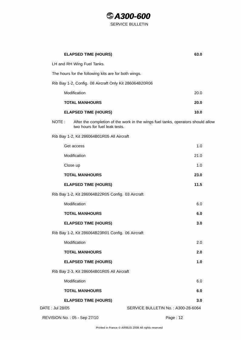
ELAPSED TIME (HOURS) 63.0
LH and RH Wing Fuel Tanks.
The hours for the following kits are for both wings.
Rib Bay 1-2, Config. 08 Aircraft Only Kit 286064B20R06
Modification 20.0
TOTAL MANHOURS 20.0
ELAPSED TIME (HOURS) 10.0
NOTE : After the completion of the work in the wings fuel tanks, operators should allowtwo hours for fuel leak tests.
Rib Bay 1-2, Kit 286064B01R05 All Aircraft
Get access 1.0
Modification 21.0
Close up 1.0
TOTAL MANHOURS 23.0
ELAPSED TIME (HOURS) 11.5
Rib Bay 1-2, Kit 286064B22R05 Config. 03 Aircraft
Modification 6.0
TOTAL MANHOURS 6.0
ELAPSED TIME (HOURS) 3.0
Rib Bay 1-2, Kit 286064B23R01 Config. 06 Aircraft
Modification 2.0
TOTAL MANHOURS 2.0
ELAPSED TIME (HOURS) 1.0
Rib Bay 2-3, Kit 286064B01R05 All Aircraft
Modification 6.0
TOTAL MANHOURS 6.0
ELAPSED TIME (HOURS) 3.0
DATE : Jul 28/05 SERVICE BULLETIN No. : A300-28-6064
REVISION No. : 05 - Sep 27/10 Page : 12
Printed in France © AIRBUS 2008 All rights reserved

A300-600A300-600SERVICE BULLETIN
Rib Bay 2-3, Kit 286064B21R01 Config. 04 Aircraft
Modification 6.0
TOTAL MANHOURS 6.0
ELAPSED TIME (HOURS) 3.0
Rib Bay 5-6, Kit 286064B03R03 All Aircraft
Get access 1.0
Modification 4.0
Close up 1.0
TOTAL MANHOURS 6.0
ELAPSED TIME (HOURS) 3.0
Rib Bay 5-6, Kit 286064B02R02 or Kit 286064B26R01 Config. 02 Aircraft
Modification 4.0
TOTAL MANHOURS 4.0
ELAPSED TIME (HOURS) 2.0
Rib Bay 8-9, Kit 286064B04R03 All Aircraft
Get access 1.0
Modification 6.0
Close up 1.0
TOTAL MANHOURS 8.0
ELAPSED TIME (HOURS) 4.0
Rib Bay 8-9, Kit 286064B02R02 or Kit 286064B26R01 Config. 02 Aircraft
Modification 4.0
TOTAL MANHOURS 4.0
ELAPSED TIME (HOURS) 2.0
Rib Bay 9-10, Kit 286064B05R01 All Aircraft
Get access 1.0
Modification 6.0
DATE : Jul 28/05 SERVICE BULLETIN No. : A300-28-6064
REVISION No. : 05 - Sep 27/10 Page : 13
Printed in France © AIRBUS 2008 All rights reserved

A300-600A300-600SERVICE BULLETIN
Close up 1.0
TOTAL MANHOURS 8.0
ELAPSED TIME (HOURS) 4.0
Rib Bay 9-10, Kit 286064B02R02 or Kit 286064B26R01 Config. 02 Aircraft
Modification 4.0
TOTAL MANHOURS 4.0
ELAPSED TIME (HOURS) 2.0
Rib Bay 10-11, Kit 286064B06R03 All Aircraft
Get access 1.0
Modification 4.0
Close up 1.0
TOTAL MANHOURS 6.0
ELAPSED TIME (HOURS) 3.0
Rib Bay 10-11, Kit 286064B02R02 or Kit 286064B26R01 Config. 02 Aircraft
Modification 4.0
TOTAL MANHOURS 4.0
ELAPSED TIME (HOURS) 2.0
Rib Bay 11-12, Kit 286064B07R01 All Aircraft
Get access 1.0
Modification 2.0
Close up 1.0
TOTAL MANHOURS 4.0
ELAPSED TIME (HOURS) 4.0
Rib Bay 12-13, Kit 286064B08R03 All Aircraft
Get access 1.0
Modification 4.0
Close up 1.0
DATE : Jul 28/05 SERVICE BULLETIN No. : A300-28-6064
REVISION No. : 05 - Sep 27/10 Page : 14
Printed in France © AIRBUS 2008 All rights reserved

A300-600A300-600SERVICE BULLETIN
TOTAL MANHOURS 6.0
ELAPSED TIME (HOURS) 3.0
Rib Bay 12-13, Kit 286064B02R02 or Kit 286064B26R01 Config. 02 Aircraft
Modification 4.0
TOTAL MANHOURS 4.0
ELAPSED TIME (HOURS) 2.0
Rib Bay 13-14, and Kit 286064B09R04 All Aircraft
Get access 1.0
Modification 6.0
Close up 1.0
TOTAL MANHOURS 8.0
ELAPSED TIME (HOURS) 4.0
Rib Bay 14-15, Kit 286064B10R01 All Aircraft
Get access 1.0
Modification 14.0
Close up 1.0
TOTAL MANHOURS 16.0
ELAPSED TIME (HOURS) 8.0
Rib Bay 14-15, Kit 286064B02R02 or Kit 286064B26R01 Config. 02 Aircraft
Modification 4.0
TOTAL MANHOURS 4.0
ELAPSED TIME (HOURS) 2.0
Rib Bay 14-15, Kit 286064B25R01 Config. 07 Aircraft
Modification 2.0
TOTAL MANHOURS 2.0
ELAPSED TIME (HOURS) 1.0
DATE : Jul 28/05 SERVICE BULLETIN No. : A300-28-6064
REVISION No. : 05 - Sep 27/10 Page : 15
Printed in France © AIRBUS 2008 All rights reserved

A300-600A300-600SERVICE BULLETIN
Rib Bay 15-16, Kit 286064B11R05 All Aircraft
Get access 1.0
Modification 8.0
Close up 1.0
TOTAL MANHOURS 10.0
ELAPSED TIME (HOURS) 5.0
Rib Bay 15-16, Kit 286064B02R02 or Kit 286064B26R01 Config. 02 Aircraft
Modification 4.0
TOTAL MANHOURS 4.0
ELAPSED TIME (HOURS) 2.0
Rib Bay 16-17, Kit 286064B12R01 All Aircraft
Get access 1.0
Modification 2.0
Close up 1.0
TOTAL MANHOURS 4.0
ELAPSED TIME (HOURS) 2.0
Rib Bay 17-18, Kit 286064B25R01 Config. 07 Aircraft
Get access 1.0
Modification 1.0
Close up 1.0
TOTAL MANHOURS 3.0
ELAPSED TIME (HOURS) 1.5
Rib Bay 18-19, Kit 286064B13R03 All Aircraft
Get access 1.0
Modification 4.0
Close up 1.0
TOTAL MANHOURS 6.0
DATE : Jul 28/05 SERVICE BULLETIN No. : A300-28-6064
REVISION No. : 05 - Sep 27/10 Page : 16
Printed in France © AIRBUS 2008 All rights reserved

A300-600A300-600SERVICE BULLETIN
ELAPSED TIME (HOURS) 3.0
Rib Bay 18-19, Kit 286064B02R02 or Kit 286064B26R01 Config. 01 and Config. 02
Modification 4.0
TOTAL MANHOURS 4.0
ELAPSED TIME (HOURS) 2.0
Rib Bay 20-21, Kit 286064B14R02 All Aircraft
Get access 1.0
Modification 4.0
Close up 1.0
TOTAL MANHOURS 6.0
ELAPSED TIME (HOURS) 3.0
Rib Bay 20-21, Kit 286064B02R02 or Kit 286064B26R01 Config. 02 Aircraft
Modification 4.0
TOTAL MANHOURS 4.0
ELAPSED TIME (HOURS) 2.0
Rib Bay 21-22, Kit 286064B15R04 All Aircraft
Get access 1.0
Modification 4.0
Close up 1.0
TOTAL MANHOURS 6.0
ELAPSED TIME (HOURS) 3.0
Rib Bay 21-22 Kit 286064B02R02 or Kit 286064B26R01 Config. 01 and Config. 02
Modification 4.0
TOTAL MANHOURS 4.0
ELAPSED TIME (HOURS) 2.0
Rib Bay 24-25, Kit 286064B16R03 All Aircraft
DATE : Jul 28/05 SERVICE BULLETIN No. : A300-28-6064
REVISION No. : 05 - Sep 27/10 Page : 17
Printed in France © AIRBUS 2008 All rights reserved

A300-600A300-600SERVICE BULLETIN
Get access 1.0
Modification 4.0
Close up 1.0
TOTAL MANHOURS 6.0
ELAPSED TIME (HOURS) 3.0
Rib Bay 24-25, Kit 286064B02R02 or Kit 286064B26R01 Config. 01 and Config. 02
Modification 4.0
TOTAL MANHOURS 4.0
ELAPSED TIME (HOURS) 2.0
Rib Bay 25-26, Kit 286064B19R02 All Aircraft
Get access 1.0
Modification 1.0
Close up 1.0
TOTAL MANHOURS 3.0
ELAPSED TIME (HOURS) 1.5
Rib Bay 26-27, Kit 286064B17R01 All Aircraft
Get access 1.0
Modification 5.0
Close up 1.0
TOTAL MANHOURS 7.0
ELAPSED TIME (HOURS) 3.5
Rib Bay 26-27, Kit 286064B27R01 or Kit 286064B28R01 Config. 02 Aircraft
Modification 5.0
TOTAL MANHOURS 5.0
ELAPSED TIME (HOURS) 2.5
Rib Bay 27-28, Kit 286064B18R04 All Aircraft
Get access 1.0
DATE : Jul 28/05 SERVICE BULLETIN No. : A300-28-6064
REVISION No. : 05 - Sep 27/10 Page : 18
Printed in France © AIRBUS 2008 All rights reserved

A300-600A300-600SERVICE BULLETIN
Modification 8.0
Close up 1.0
TOTAL MANHOURS 10.0
ELAPSED TIME (HOURS) 5.0
Rib Bay 27-28, Kit 286064B02R02 or Kit 286064B26R01 Config. 01 and Config. 02
Modification 4.0
TOTAL MANHOURS 4.0
ELAPSED TIME (HOURS) 2.0
NOTE : The overall manhours for the wings fuel tanks can vary between 162 total manhours,elapsed time 83 manhours and 226 total manhours, 113 elapsed time manhours,depending on the aircraft configuration.
NOTE : After the completion of the work in the wings fuel tanks, operators should allowtwo hours for fuel leak tests.
ADDITIONAL WORK on LH wing tank (Introduced by Rev 01)
Rib Bay 13-14, Kit 286064B39R00 All Aircraft
Get access 0.5
Modification 1.0
Close up 0.5
TOTAL MANHOURS 2.0
ELAPSED TIME (HOURS) 2.0
ADDITIONAL WORK on center tank (Introduced by Rev 03)
Get access 30.0
Check of the bonding points 1.0
Test 1.5
Close-up 30.0
TOTAL MANHOURS 62.5
ELAPSED TIME (HOURS) 31.0
ADDITIONAL WORK on wings tanks (Introduced by Rev 04)
DATE : Jul 28/05 SERVICE BULLETIN No. : A300-28-6064
REVISION No. : 05 - Sep 27/10 Page : 19
Printed in France © AIRBUS 2008 All rights reserved

A300-600A300-600SERVICE BULLETIN
Rib Bay 14-15, Kit 286064B25R01 Config. 07 Aircraft
Get access 1.0
Modification 2.0
Close up 1.0
TOTAL MANHOURS 4.0
ELAPSED TIME (HOURS) 2.0
ADDITIONAL WORK on wings tanks (Introduced by Rev 04)
Rib Bay 17-18, Kit 286064B25R01 Config. 07 Aircraft
Get access 1.0
Modification 2.0
Close up 1.0
TOTAL MANHOURS 4.0
ELAPSED TIME (HOURS) 2.0
ADDITIONAL WORK on center tank (For aircraft using Kit A03 only)
Get access 30.0
Install the bonding points 3.0
Test 1.5
Close-up 30.0
TOTAL MANHOURS 64.5
ELAPSED TIME (HOURS) 31.0
H. WEIGHT AND BALANCE
Not changed
I. ELECTRICAL LOAD DATA
Not changed
DATE : Jul 28/05 SERVICE BULLETIN No. : A300-28-6064
REVISION No. : 05 - Sep 27/10 Page : 20
Printed in France © AIRBUS 2008 All rights reserved

A300-600A300-600SERVICE BULLETIN
J. REFERENCES
Aircraft Maintenance Manual (AMM) : 06-41-57 20-28-11 24-00-00 24-31-1124-41-00 27-80-00 28-00-00 28-10-0028-11-00 28-11-22 28-11-29 28-25-0028-25-21 28-42-00 33-13-00 33-14-0057-20-43 57-23-11
Elec. Std. Practices Manual (ESPM) : 20-51-10 20-55-00
Service Information Letter (SIL) : 28-072
Structural Repair Manual (SRM) : 51-40-20 51-40-30 51-40-44 51-43-0051-75-10 51-76-10 51-76-20
Consumable Materials List (CML)
Service Bulletin (SB) : A300-28-6028 A300-28-6069A300-28-6089 A300-57-6026A300-57-6070
K. PUBLICATIONS AFFECTED
Aircraft Maintenance Manual (AMM) : 28-11-21 28-12-15 28-21-13 28-21-2128-25-15 28-25-21 28-42-23 28-42-2428-42-35 28-42-36 28-42-44 28-42-4528-43-21 28-46-21 28-46-22 57-20-43
Illustrated Parts Catalogue (IPC) : 28-11-05 28-11-11 28-11-12 28-21-1328-21-21 28-25-03 28-25-05 28-25-1228-26-03 28-42-44 28-43-05 57-20-43
L. INTERCHANGEABILITY/MIXABILITY
None
DATE : Jul 28/05 SERVICE BULLETIN No. : A300-28-6064
REVISION No. : 05 - Sep 27/10 Page : 21
Printed in France © AIRBUS 2008 All rights reserved

A300-600A300-600SERVICE BULLETIN
This Page Intentionally Left Blank
DATE : Jul 28/05 SERVICE BULLETIN No. : A300-28-6064
REVISION No. : 05 - Sep 27/10 Page : 22
Printed in France © AIRBUS 2008 All rights reserved

A300-600A300-600SERVICE BULLETIN
2. MATERIAL INFORMATION
A. MATERIAL - PRICE AND AVAILABILITY
(1) Material
Operators with aircraft shown in the effectivity of this Service Bulletin should submit apurchase order to AIRBUS. Quote the number of this Service Bulletin. The address is:
AIRBUS Material Logistics and SuppliersWeg beim Jaeger 150P.O. Box 630262D-22335 HAMBURGGERMANYFor ordering by internet: http://spares.airbus.comFor ordering by fax: +49 40 50 76 25 90
(2) Price and Availability
Kit 286064A01R05
Cost : 181,00 US dollars
Availability : 30 calendar days from receipt of order
The sales terms (Cost and Availability) are estimated in relation to economic conditionsat the issue date of this Service Bulletin.
Kit 286064A02R02
Cost : 119,00 US dollars
Availability : 30 calendar days from receipt of order
The sales terms (costs and availability) are estimated in relation to economic conditionsat the issue date of the Service Bulletin.
Kit 286064A03R00
Cost : 137,00 US dollars
Availability : 30 calendar days from receipt of order
The sales terms (costs and availability) are estimated in relation to economic conditionsat the issue date of the Service Bulletin.
Kit 286064B01R05
Cost : 214,00 US dollars
Availability : 30 calendar days from receipt of order
DATE : Jul 28/05 SERVICE BULLETIN No. : A300-28-6064
REVISION No. : 05 - Sep 27/10 Page : 23
Printed in France © AIRBUS 2008 All rights reserved

A300-600A300-600SERVICE BULLETIN
The sales terms (Cost and Availability) are estimated in relation to economic conditionsat the issue date of this Service Bulletin.
Kit 286064B02R02
Cost : 40,00 US dollars
Availability : 30 calendar days from receipt of order
The sales terms (Cost and Availability) are estimated in relation to economic conditionsat the issue date of this Service Bulletin.
Kit 286064B03R03
Cost : 80,00 US dollars
Availability : 30 calendar days from receipt of order
The sales terms (Cost and Availability) are estimated in relation to economic conditionsat the issue date of this Service Bulletin.
Kit 286064B04R03
Cost : 105,00 US dollars
Availability : 30 calendar days from receipt of order
The sales terms (Cost and Availability) are estimated in relation to economic conditionsat the issue date of this Service Bulletin.
Kit 286064B05R01
Cost : 100,00 US dollars
Availability : 30 calendar days from receipt of order
The sales terms (Cost and Availability) are estimated in relation to economic conditionsat the issue date of this Service Bulletin.
Kit 286064B06R03
Cost : 300,00 US dollars
Availability : 30 calendar days from receipt of order
The sales terms (Cost and Availability) are estimated in relation to economic conditionsat the issue date of this Service Bulletin.
Kit 286064B07R01
Cost : 17,00 US dollars
Availability : 30 calendar days from receipt of order
DATE : Jul 28/05 SERVICE BULLETIN No. : A300-28-6064
REVISION No. : 05 - Sep 27/10 Page : 24
Printed in France © AIRBUS 2008 All rights reserved
A300-600A300-600SERVICE BULLETIN
The sales terms (Cost and Availability) are estimated in relation to economic conditionsat the issue date of this Service Bulletin.
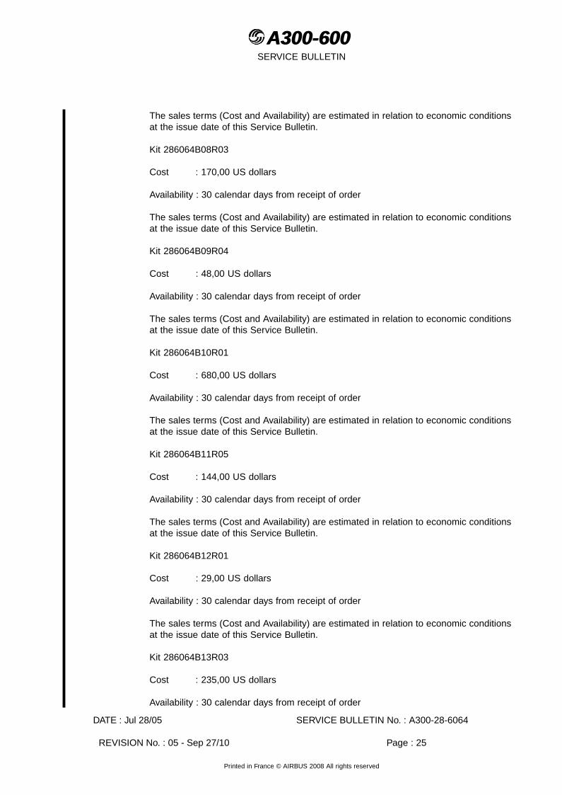
Kit 286064B08R03
Cost : 170,00 US dollars
Availability : 30 calendar days from receipt of order
The sales terms (Cost and Availability) are estimated in relation to economic conditionsat the issue date of this Service Bulletin.
Kit 286064B09R04
Cost : 48,00 US dollars
Availability : 30 calendar days from receipt of order
The sales terms (Cost and Availability) are estimated in relation to economic conditionsat the issue date of this Service Bulletin.
Kit 286064B10R01
Cost : 680,00 US dollars
Availability : 30 calendar days from receipt of order
The sales terms (Cost and Availability) are estimated in relation to economic conditionsat the issue date of this Service Bulletin.
Kit 286064B11R05
Cost : 144,00 US dollars
Availability : 30 calendar days from receipt of order
The sales terms (Cost and Availability) are estimated in relation to economic conditionsat the issue date of this Service Bulletin.
Kit 286064B12R01
Cost : 29,00 US dollars
Availability : 30 calendar days from receipt of order
The sales terms (Cost and Availability) are estimated in relation to economic conditionsat the issue date of this Service Bulletin.
Kit 286064B13R03
Cost : 235,00 US dollars
Availability : 30 calendar days from receipt of order
DATE : Jul 28/05 SERVICE BULLETIN No. : A300-28-6064
REVISION No. : 05 - Sep 27/10 Page : 25
Printed in France © AIRBUS 2008 All rights reserved

A300-600A300-600SERVICE BULLETIN
The sales terms (Cost and Availability) are estimated in relation to economic conditionsat the issue date of this Service Bulletin.
Kit 286064B14R02
Cost : 197,00 US dollars
Availability : 30 calendar days from receipt of order
The sales terms (Cost and Availability) are estimated in relation to economic conditionsat the issue date of this Service Bulletin.
Kit 286064B15R04
Cost : 183,00 US dollars
Availability : 30 calendar days from receipt of order
The sales terms (Cost and Availability) are estimated in relation to economic conditionsat the issue date of this Service Bulletin.
Kit 286064B16R03
Cost : 138,00 US dollars
Availability : 30 calendar days from receipt of order
The sales terms (Cost and Availability) are estimated in relation to economic conditionsat the issue date of this Service Bulletin.
Kit 286064B17R01
Cost : 183,00 US dollars
Availability : 30 calendar days from receipt of order
The sales terms (Cost and Availability) are estimated in relation to economic conditionsat the issue date of this Service Bulletin.
Kit 286064B18R04
Cost : 170,00 US dollars
Availability : 30 calendar days from receipt of order
The sales terms (Cost and Availability) are estimated in relation to economic conditionsat the issue date of this Service Bulletin.
Kit 286064B19R02
Cost : 40,00 US dollars
Availability : 30 calendar days from receipt of order
DATE : Jul 28/05 SERVICE BULLETIN No. : A300-28-6064
REVISION No. : 05 - Sep 27/10 Page : 26
Printed in France © AIRBUS 2008 All rights reserved

A300-600A300-600SERVICE BULLETIN
The sales terms (Cost and Availability) are estimated in relation to economic conditionsat the issue date of this Service Bulletin.
Kit 286064B20R06
Cost : 261,00 US dollars
Availability : 30 calendar days from receipt of order
The sales terms (Cost and Availability) are estimated in relation to economic conditionsat the issue date of this Service Bulletin.
Kit 286064B21R01
Cost : 170,00 US dollars
Availability : 30 calendar days from receipt of order
The sales terms (Cost and Availability) are estimated in relation to economic conditionsat the issue date of this Service Bulletin.
Kit 286064B22R05
Cost : 62,00 US dollars
Availability : 30 calendar days from receipt of order
The sales terms (Cost and Availability) are estimated in relation to economic conditionsat the issue date of this Service Bulletin.
Kit 286064B23R01
Cost : 17,00 US dollars
Availability : 30 calendar days from receipt of order
The sales terms (Cost and Availability) are estimated in relation to economic conditionsat the issue date of this Service Bulletin.
Kit 286064B25R01
Cost : 157,00 US dollars
Availability : 30 calendar days from receipt of order
The sales terms (Cost and Availability) are estimated in relation to economic conditionsat the issue date of this Service Bulletin.
Kit 286064B26R01
Cost : 40,00 US dollars
Availability : 30 calendar days from receipt of order
DATE : Jul 28/05 SERVICE BULLETIN No. : A300-28-6064
REVISION No. : 05 - Sep 27/10 Page : 27
Printed in France © AIRBUS 2008 All rights reserved

A300-600A300-600SERVICE BULLETIN
The sales terms (Cost and Availability) are estimated in relation to economic conditionsat the issue date of this Service Bulletin.
Kit 286064B27R01
Cost : 197,00 US dollars
Availability : 30 calendar days from receipt of order
The sales terms (Cost and Availability) are estimated in relation to economic conditionsat the issue date of this Service Bulletin.
Kit 286064B28R01
Cost : 197,00 US dollars
Availability : 30 calendar days from receipt of order
The sales terms (Cost and Availability) are estimated in relation to economic conditionsat the issue date of this Service Bulletin.
NOTE : The kits availability given above is the standard lead time from the date of yourpurchase order. If you require the Kits before this time, please include yourretrofit planning schedule with your order so that we can try to comply withyour requirements.
ADDITIONAL WORK (Introduced by Rev 01)
Kit 286064B39R00
Cost : 26,00 US dollars
Availability : 30 calendar days from receipt of order
The sales terms (Cost and Availability) are estimated in relation to economic conditionsat the issue date of this Service Bulletin.
NOTE : The kits availability given above is the standard lead time from the date of yourpurchase order. If you require the Kits before this time, please include yourretrofit planning schedule with your order so that we can try to comply withyour requirements.
B. INDUSTRY SUPPORT INFORMATION
AIRBUS will not provide industry support for accomplishment of this Service Bulletin.
DATE : Jul 28/05 SERVICE BULLETIN No. : A300-28-6064
REVISION No. : 05 - Sep 27/10 Page : 28
Printed in France © AIRBUS 2008 All rights reserved
A300-600A300-600SERVICE BULLETIN
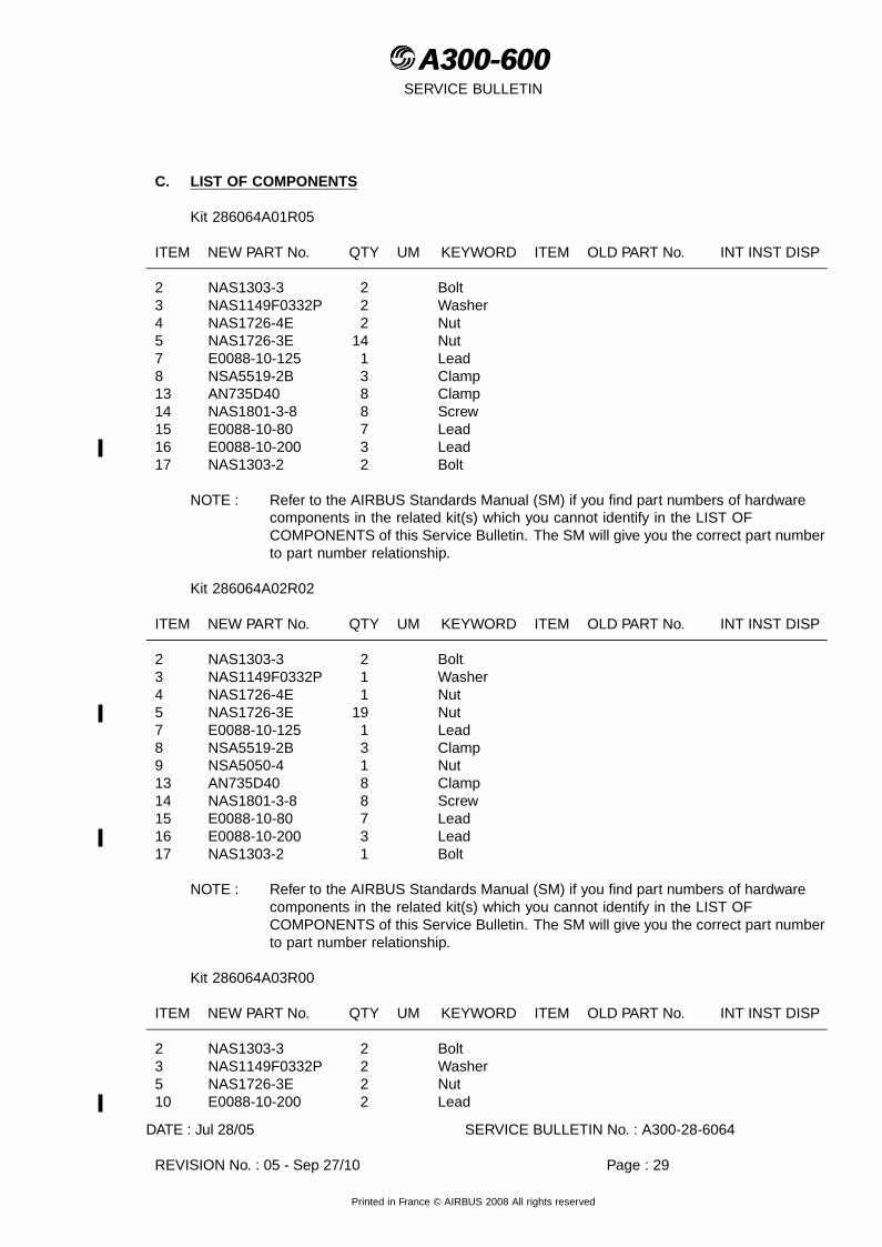
C. LIST OF COMPONENTS
Kit 286064A01R05
ITEM NEW PART No. QTY UM KEYWORD ITEM OLD PART No. INT INST DISP
2 NAS1303-3 2 Bolt3 NAS1149F0332P 2 Washer4 NAS1726-4E 2 Nut5 NAS1726-3E 14 Nut7 E0088-10-125 1 Lead8 NSA5519-2B 3 Clamp13 AN735D40 8 Clamp14 NAS1801-3-8 8 Screw15 E0088-10-80 7 Lead16 E0088-10-200 3 Lead17 NAS1303-2 2 Bolt
NOTE : Refer to the AIRBUS Standards Manual (SM) if you find part numbers of hardwarecomponents in the related kit(s) which you cannot identify in the LIST OFCOMPONENTS of this Service Bulletin. The SM will give you the correct part numberto part number relationship.
Kit 286064A02R02
ITEM NEW PART No. QTY UM KEYWORD ITEM OLD PART No. INT INST DISP
2 NAS1303-3 2 Bolt3 NAS1149F0332P 1 Washer4 NAS1726-4E 1 Nut5 NAS1726-3E 19 Nut7 E0088-10-125 1 Lead8 NSA5519-2B 3 Clamp9 NSA5050-4 1 Nut13 AN735D40 8 Clamp14 NAS1801-3-8 8 Screw15 E0088-10-80 7 Lead16 E0088-10-200 3 Lead17 NAS1303-2 1 Bolt
NOTE : Refer to the AIRBUS Standards Manual (SM) if you find part numbers of hardwarecomponents in the related kit(s) which you cannot identify in the LIST OFCOMPONENTS of this Service Bulletin. The SM will give you the correct part numberto part number relationship.
Kit 286064A03R00
ITEM NEW PART No. QTY UM KEYWORD ITEM OLD PART No. INT INST DISP
2 NAS1303-3 2 Bolt3 NAS1149F0332P 2 Washer5 NAS1726-3E 2 Nut10 E0088-10-200 2 Lead
DATE : Jul 28/05 SERVICE BULLETIN No. : A300-28-6064
REVISION No. : 05 - Sep 27/10 Page : 29
Printed in France © AIRBUS 2008 All rights reserved

A300-600A300-600SERVICE BULLETIN
ITEM NEW PART No. QTY UM KEYWORD ITEM OLD PART No. INT INST DISP
11 ASNA2050DCJ3215 4 Rivet12 A9242127720000 2 Angle
Kit 286064B01R05
ITEM NEW PART No. QTY UM KEYWORD ITEM OLD PART No. INT INST DISP
4 NSA5472-4K7 4 Nut14 E0088-41-160 1 Lead15 AN742D6 1 Clamp16 NSA5474-3K7 11 Nut17 NSA5020-3-3 3 Bolt20 NSA5474-4K7 7 Nut25 H19200C4 1 Nut27 NSA5041VBV3-4 1 Bolt28 AN960C10L 1 Washer34 NSA5041VBV3-10 2 Bolt35 NSA5519-2B 4 Clamp37 NAS1303-2 4 Bolt38 E0088-10-100 2 Lead39 E0088-41-100 2 Lead45 NSA5022-4-21 4 Screw46 NAS1304-3 4 Bolt49 NSA5472-5K7 5 Nut52 A2824028520000 3 Washer53 AN960PD416 3 Washer74 AN960KD10L 2 Washer77 NSA5041VBV3-8 1 Bolt
Kit 286064B02R02
ITEM NEW PART No. QTY UM KEYWORD ITEM OLD PART No. INT INST DISP
4 NSA5472-4K7 4 Nut9 A5715206420000 1 Plate13 NAS1252-416L 1 Washer
Kit 286064B03R03
ITEM NEW PART No. QTY UM KEYWORD ITEM OLD PART No. INT INST DISP
2 NSA5020-3-6 1 Bolt4 NSA5472-4K7 2 Nut5 AN960C416L 1 Washer6 NSA5041VBV4-2 1 Bolt16 NSA5474-3K7 1 Nut70 NSA5020-3-2 1 Bolt
DATE : Jul 28/05 SERVICE BULLETIN No. : A300-28-6064
REVISION No. : 05 - Sep 27/10 Page : 30
Printed in France © AIRBUS 2008 All rights reserved

A300-600A300-600SERVICE BULLETIN
Kit 286064B04R03
ITEM NEW PART No. QTY UM KEYWORD ITEM OLD PART No. INT INST DISP
4 NSA5472-4K7 2 Nut5 AN960C416L 1 Washer16 NSA5474-3K7 1 Nut17 NSA5020-3-3 1 Bolt25 H19200C4 1 Nut30 NSA5041VBV4-3 1 Bolt88 AN960KD10 1 Washer
Kit 286064B05R01
ITEM NEW PART No. QTY UM KEYWORD ITEM OLD PART No. INT INST DISP
1 E0088-40-100 1 Lead3 NSA5041VBV4-11 1 Bolt4 NSA5472-4K7 2 Nut5 AN960C416L 1 Washer7 NSA5041VBV3-5 1 Bolt14 E0088-41-160 1 Lead15 AN742D6 1 Clamp16 NSA5474-3K7 3 Nut17 NSA5020-3-3 1 Bolt19 ABS0114-4-18 1 Bolt20 NSA5474-4K7 1 Nut31 NAS1303-10 1 Bolt
Kit 286064B06R03
ITEM NEW PART No. QTY UM KEYWORD ITEM OLD PART No. INT INST DISP
1 E0088-40-100 1 Lead4 NSA5472-4K7 3 Nut5 AN960C416L 1 Washer16 NSA5474-3K7 1 Nut18 NSA5472-3K7 1 Nut28 AN960C10L 1 Washer32 NSA5041VBV4-9 1 Bolt33 NSA5041VBV3-3 1 Bolt40 ABS0114-4-16 1 Bolt70 NSA5020-3-2 1 Bolt
Kit 286064B07R01
ITEM NEW PART No. QTY UM KEYWORD ITEM OLD PART No. INT INST DISP
16 NSA5474-3K7 2 Nut20 NSA5474-4K7 1 Nut39 E0088-41-100 1 Lead50 AN742D8 1 Clamp51 NAS1100-3-7 1 Screw
DATE : Jul 28/05 SERVICE BULLETIN No. : A300-28-6064
REVISION No. : 05 - Sep 27/10 Page : 31
Printed in France © AIRBUS 2008 All rights reserved

A300-600A300-600SERVICE BULLETIN
ITEM NEW PART No. QTY UM KEYWORD ITEM OLD PART No. INT INST DISP
55 NAS1304-11 1 Bolt56 NAS1303-7 1 Bolt58 NAS1304-14 1 Bolt
Kit 286064B08R03
ITEM NEW PART No. QTY UM KEYWORD ITEM OLD PART No. INT INST DISP
4 NSA5472-4K7 3 Nut5 AN960C416L 1 Washer16 NSA5474-3K7 2 Nut28 AN960C10L 1 Washer32 NSA5041VBV4-9 1 Bolt41 NSA5041VBV3-2 1 Bolt42 NAS1303-1 1 Bolt44 ABS0114-4-15 1 Bolt89 E0088-40-190 1 Lead
Kit 286064B09R04
ITEM NEW PART No. QTY UM KEYWORD ITEM OLD PART No. INT INST DISP
16 NSA5474-3K7 4 Nut17 NSA5020-3-3 1 Bolt20 NSA5474-4K7 2 Nut25 H19200C4 1 Nut51 NAS1100-3-7 2 Screw59 E0088-41-304 2 Lead70 NSA5020-3-2 1 Bolt90 NSA5020-3-5 1 Bolt
Kit 286064B10R01
ITEM NEW PART No. QTY UM KEYWORD ITEM OLD PART No. INT INST DISP
1 E0088-40-100 1 Lead4 NSA5472-4K7 2 Nut5 AN960C416L 1 Washer7 NSA5041VBV3-5 1 Bolt14 E0088-41-160 1 Lead15 AN742D6 1 Clamp16 NSA5474-3K7 8 Nut17 NSA5020-3-3 1 Bolt18 NSA5472-3K7 2 Nut20 NSA5474-4K7 3 Nut26 NSA5041VBV3-7 1 Bolt35 NSA5519-2B 4 Clamp37 NAS1303-2 4 Bolt38 E0088-10-100 2 Lead39 E0088-41-100 2 Lead
DATE : Jul 28/05 SERVICE BULLETIN No. : A300-28-6064
REVISION No. : 05 - Sep 27/10 Page : 32
Printed in France © AIRBUS 2008 All rights reserved

A300-600A300-600SERVICE BULLETIN
ITEM NEW PART No. QTY UM KEYWORD ITEM OLD PART No. INT INST DISP
45 NSA5022-4-21 4 Screw54 NSA5041VBV4-7 1 Bolt57 ABS0114-4-14 1 Bolt69 NSA5041VBV3-6 2 Bolt
Kit 286064B11R05
ITEM NEW PART No. QTY UM KEYWORD ITEM OLD PART No. INT INST DISP
1 E0088-40-100 1 Lead4 NSA5472-4K7 5 Nut5 AN960C416L 1 Washer14 E0088-41-160 1 Lead15 AN742D6 1 Clamp16 NSA5474-3K7 1 Nut17 NSA5020-3-3 1 Bolt18 NSA5472-3K7 2 Nut20 NSA5474-4K7 3 Nut28 AN960C10L 1 Washer29 NSA5041VBV4-8 1 Bolt33 NSA5041VBV3-3 1 Bolt46 NAS1304-3 2 Bolt49 NSA5472-5K7 2 Nut52 A2824028520000 2 Washer53 AN960PD416 1 Washer70 NSA5020-3-2 1 Bolt85 ABS0114-4-13 1 Bolt
Kit 286064B12R01
ITEM NEW PART No. QTY UM KEYWORD ITEM OLD PART No. INT INST DISP
16 NSA5474-3K7 2 Nut70 NSA5020-3-2 1 Bolt71 NSA5020-3-4 1 Bolt
Kit 286064B13R03
ITEM NEW PART No. QTY UM KEYWORD ITEM OLD PART No. INT INST DISP
1 E0088-40-100 1 Lead4 NSA5472-4K7 3 Nut5 AN960C416L 1 Washer16 NSA5474-3K7 1 Nut18 NSA5472-3K7 1 Nut28 AN960C10L 1 Washer29 NSA5041VBV4-8 1 Bolt33 NSA5041VBV3-3 1 Bolt42 NAS1303-1 1 Bolt61 ABS0114-4-12 1 Bolt
DATE : Jul 28/05 SERVICE BULLETIN No. : A300-28-6064
REVISION No. : 05 - Sep 27/10 Page : 33
Printed in France © AIRBUS 2008 All rights reserved
A300-600A300-600SERVICE BULLETIN
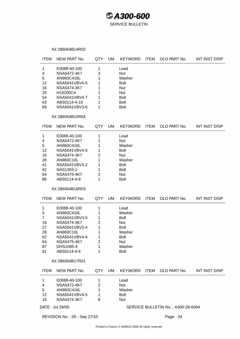
Kit 286064B14R02
ITEM NEW PART No. QTY UM KEYWORD ITEM OLD PART No. INT INST DISP
1 E0088-40-100 1 Lead4 NSA5472-4K7 3 Nut5 AN960C416L 1 Washer12 NSA5041VBV4-5 1 Bolt16 NSA5474-3K7 1 Nut25 H19200C4 1 Nut54 NSA5041VBV4-7 1 Bolt63 ABS0114-4-10 1 Bolt69 NSA5041VBV3-6 1 Bolt
Kit 286064B15R04
ITEM NEW PART No. QTY UM KEYWORD ITEM OLD PART No. INT INST DISP
1 E0088-40-100 1 Lead4 NSA5472-4K7 1 Nut5 AN960C416L 1 Washer12 NSA5041VBV4-5 1 Bolt16 NSA5474-3K7 2 Nut28 AN960C10L 1 Washer41 NSA5041VBV3-2 1 Bolt42 NAS1303-1 1 Bolt64 NSA5475-4K7 2 Nut86 ABS0114-4-9 1 Bolt
Kit 286064B16R03
ITEM NEW PART No. QTY UM KEYWORD ITEM OLD PART No. INT INST DISP
1 E0088-40-100 1 Lead5 AN960C416L 1 Washer7 NSA5041VBV3-5 1 Bolt16 NSA5474-3K7 2 Nut27 NSA5041VBV3-4 1 Bolt28 AN960C10L 1 Washer62 NSA5041VBV4-6 1 Bolt64 NSA5475-4K7 2 Nut87 DHS1085-4 1 Washer91 ABS0114-4-6 1 Bolt
Kit 286064B17R01
ITEM NEW PART No. QTY UM KEYWORD ITEM OLD PART No. INT INST DISP
1 E0088-40-100 1 Lead4 NSA5472-4K7 2 Nut5 AN960C416L 1 Washer12 NSA5041VBV4-5 1 Bolt16 NSA5474-3K7 8 Nut
DATE : Jul 28/05 SERVICE BULLETIN No. : A300-28-6064
REVISION No. : 05 - Sep 27/10 Page : 34
Printed in France © AIRBUS 2008 All rights reserved

A300-600A300-600SERVICE BULLETIN
ITEM NEW PART No. QTY UM KEYWORD ITEM OLD PART No. INT INST DISP
18 NSA5472-3K7 1 Nut20 NSA5474-4K7 1 Nut28 AN960C10L 1 Washer67 ABS0114-4-5 1 Bolt72 ABS0114-3-6 1 Bolt
Kit 286064B18R04
ITEM NEW PART No. QTY UM KEYWORD ITEM OLD PART No. INT INST DISP
1 E0088-40-100 1 Lead5 AN960C416L 1 Washer7 NSA5041VBV3-5 3 Bolt16 NSA5474-3K7 3 Nut20 NSA5474-4K7 1 Nut30 NAS1304-4 2 Bolt64 NSA5475-4K7 2 Nut65 DHS783-63-18 1 Washer78 NSA5041VBV4-4 1 Bolt79 ABS0114-4-4 1 Bolt87 DHS1085-4 1 Washer
Kit 286064B19R02
ITEM NEW PART No. QTY UM KEYWORD ITEM OLD PART No. INT INST DISP
16 NSA5474-3K7 1 Nut17 NSA5020-3-3 1 Bolt71 NSA5020-3-4 1 Bolt
Kit 286064B20R06
ITEM NEW PART No. QTY UM KEYWORD ITEM OLD PART No. INT INST DISP
14 E0088-41-160 1 Lead15 AN742D6 1 Clamp16 NSA5474-3K7 15 Nut17 NSA5020-3-3 3 Bolt20 NSA5474-4K7 5 Nut25 H19200C4 1 Nut27 NSA5041VBV3-4 1 Bolt28 AN960C10L 1 Washer34 NSA5041VBV3-10 2 Bolt35 NSA5519-2B 4 Clamp37 NAS1303-2 8 Bolt38 E0088-10-100 2 Lead39 E0088-41-100 2 Lead45 NSA5022-4-21 4 Screw46 NAS1304-3 2 Bolt52 A2824028520000 1 Washer
DATE : Jul 28/05 SERVICE BULLETIN No. : A300-28-6064
REVISION No. : 05 - Sep 27/10 Page : 35
Printed in France © AIRBUS 2008 All rights reserved

A300-600A300-600SERVICE BULLETIN
ITEM NEW PART No. QTY UM KEYWORD ITEM OLD PART No. INT INST DISP
53 AN960PD416 2 Washer74 AN960KD10L 2 Washer77 NSA5041VBV3-8 1 Bolt
Kit 286064B21R01
ITEM NEW PART No. QTY UM KEYWORD ITEM OLD PART No. INT INST DISP
16 NSA5474-3K7 2 Nut17 NSA5020-3-3 1 Bolt77 NSA5041VBV3-8 1 Bolt
Kit 286064B22R05
ITEM NEW PART No. QTY UM KEYWORD ITEM OLD PART No. INT INST DISP
16 NSA5474-3K7 7 Nut23 NAS1303-8 1 Bolt37 NAS1303-2 4 Bolt82 NSA5480PN3-5 2 Bolt
Kit 286064B23R01
ITEM NEW PART No. QTY UM KEYWORD ITEM OLD PART No. INT INST DISP
16 NSA5474-3K7 1 Nut17 NSA5020-3-3 1 Bolt38 E0088-10-100 1 Lead83 NSA5519-4B 1 Clamp
Kit 286064B25R01
ITEM NEW PART No. QTY UM KEYWORD ITEM OLD PART No. INT INST DISP
16 NSA5474-3K7 2 Nut20 NSA5474-4K7 2 Nut62 NSA5041VBV4-6 1 Bolt66 NAS1153-12 1 Screw68 NSA5041VBV4-14 1 Bolt69 NSA5041VBV3-6 1 Bolt
Kit 286064B26R01
ITEM NEW PART No. QTY UM KEYWORD ITEM OLD PART No. INT INST DISP
4 NSA5472-4K7 4 Nut10 A5715206420100 1 Plate13 NAS1252-416L 1 Washer
DATE : Jul 28/05 SERVICE BULLETIN No. : A300-28-6064
REVISION No. : 05 - Sep 27/10 Page : 36
Printed in France © AIRBUS 2008 All rights reserved

A300-600A300-600SERVICE BULLETIN
Kit 286064B27R01
ITEM NEW PART No. QTY UM KEYWORD ITEM OLD PART No. INT INST DISP
4 NSA5472-4K7 5 Nut9 A5715206420000 1 Plate12 NSA5041VBV4-5 4 Bolt13 NAS1252-416L 1 Washer
Kit 286064B28R01
ITEM NEW PART No. QTY UM KEYWORD ITEM OLD PART No. INT INST DISP
4 NSA5472-4K7 5 Nut10 A5715206420100 1 Plate12 NSA5041VBV4-5 4 Bolt13 NAS1252-416L 1 Washer
Kit 286064B39R00 (ADDITIONAL WORK Introduced by Rev 01)
ITEM NEW PART No. QTY UM KEYWORD ITEM OLD PART No. INT INST DISP
16 NSA5474-3K7 2 Nut20 NSA5474-4K7 2 Nut51 NAS1100-3-7 2 Screw59 E0088-41-304 2 Lead
NOTE : Refer to the AIRBUS Standards Manual (SM) if you find part numbers of hardwarecomponents in the related kit(s) which you cannot identify in the LIST OFCOMPONENTS of this Service Bulletin. The SM will give you the correct part numberto part number relationship.
D. LIST OF MATERIALS - OPERATOR SUPPLIED
(1) Consumable Materials
DESCRIPTION REFERENCE TO CML QTY PER A/C INST/DISPMAT No.
Sealant Mat. No. 09-001 As requiredSealant Mat. No. 09-002 As requiredLow Density Fuel Tank Sealant Mat. No. 09-002D As requiredCorrosion Inhibiting BrushConsistency
Mat. No. 09-013B As required
Corrosion Inhibiting FilletConsistency
Mat. No. 09-016B As required
Sealant Mat. No. 09-018 As requiredCorrosion Inhibiting SealantSprayable
Mat. No. 09-025 As required
Sealant Mat. No. 09-530 As requiredCleaning agent Mat. No. 11-026 As requiredAlodine Mat. No. 13-002 As requiredPrimer Mat. No. 16-001C As required
DATE : Jul 28/05 SERVICE BULLETIN No. : A300-28-6064
REVISION No. : 05 - Sep 27/10 Page : 37
Printed in France © AIRBUS 2008 All rights reserved

A300-600A300-600SERVICE BULLETIN
DESCRIPTION REFERENCE TO CML QTY PER A/C INST/DISPMAT No.
Varnish Mat. No. 16-021 As required
NOTE : To accomplish this Service Bulletin it is necessary to use the expendable partslisted in the AMM 28-25-21 P. Block 401.
(2) Components
Center Tank
ITEM NEW PART No. QTY UM KEYWORD ITEM OLD PART No. INT INST DISP
EN6115V5-15 1 ScrewEN6115V5-16 1 ScrewNSA5041VP4-11 2 ScrewNSA5041-3-9 1 ScrewNSA5061-3 1 WasherNSA5061-4 5 WasherNSA5112-03 1 WasherNSA5112-04 3 WasherNSA5050-3 48 NutNSA5050-4 21 NutNSA5050-5 2 NutNSA5050-6 4 NutNSA5075-6 2 NutNSA5182-4 2 NutNSA5182-3 2 NutNAS1726-3E 1 NutNAS1726-4E 7 NutASNA2529-4 2 NutASNA2529-5 2 NutASNA2029-3 2 NutNSA5355-4CA 1 NutASNA2050DXJ4828 2 RivetASNA2050DCJ3215 54 RivetASNA2050DCJ4020 2 Rivet
Additional Work on center tank (Introduced by revision 03)
ITEM NEW PART No. QTY UM KEYWORD ITEM OLD PART No. INT INST DISP
NSA5061-3 1 WasherNSA5112-04 1 Washer
ITEM NEW PART No. QTY UM KEYWORD ITEM OLD PART No. INT INST DISP
17 NAS1303-2 1 Screw20 NAS1149D0316H 1 Washer
DATE : Jul 28/05 SERVICE BULLETIN No. : A300-28-6064
REVISION No. : 05 - Sep 27/10 Page : 38
Printed in France © AIRBUS 2008 All rights reserved

A300-600A300-600SERVICE BULLETIN
E. PARTS TO BE RE-IDENTIFIED BY THE OPERATOR
None
F. TOOLING - PRICE AND AVAILABILITY
None
G. SPECIAL TOOLS
None
DATE : Jul 28/05 SERVICE BULLETIN No. : A300-28-6064
REVISION No. : 05 - Sep 27/10 Page : 39
Printed in France © AIRBUS 2008 All rights reserved

A300-600A300-600SERVICE BULLETIN
This Page Intentionally Left Blank
DATE : Jul 28/05 SERVICE BULLETIN No. : A300-28-6064
REVISION No. : 05 - Sep 27/10 Page : 40
Printed in France © AIRBUS 2008 All rights reserved

A300-600A300-600SERVICE BULLETIN
3. ACCOMPLISHMENT INSTRUCTIONS
A. GENERAL
WARNING : MAKE SURE THAT YOU OBEY ALL THE WARNINGS AND ALL THE CAUTIONSINCLUDED IN THE REFERENCED PROCEDURES.
WARNING : MAKE SURE THAT ALL THE FLIGHT CONTROLS GROUND SAFETY LOCKSAND NOTICES ARE IN POSITION BEFORE YOU START THIS MODIFICATION.
WARNING : BEFORE YOU DO ANY WORK ON THE FUEL SYSTEM OBEY THE SAFETYPRECAUTIONS (REFER TO AMM 28-00-00 PAGE BLOCK 301).
WARNING : DO NOT DO ANY WORK IN THE FUEL TANKS UNTIL THE VAPORCONCENTRATION IS BELOW 20% OF THE LOWER EXPLOSION LIMIT (LEL).
WARNING : OBEY THE MANUFACTURER’S SAFETY INSTRUCTIONS WHEN YOU USESEALANTS, VARNISH AND CLEANING AGENTS IN THE FUEL TANKS.
CAUTION : ALWAYS OBEY THE PRECAUTIONS THAT FOLLOW TO KEEP ELECTRICALWIRING IN A SATISFACTORY CONDITION (ELECTRICALLY AND MECHANICALLYSERVICEABLE). WHEN YOU DO MAINTENANCE WORK, REPAIRS ORMODIFICATIONS, ALWAYS KEEP ELECTRICAL WIRING, COMPONENTS ANDTHE WORK AREA AS CLEAN AS POSSIBLE, TO DO THIS :
- PUT PROTECTION, SUCH AS PLASTIC SHEETING, CLOTHS, ETC; ASNECESSARY ON WIRING AND COMPONENTS
- REGULARLY REMOVE ALL SHAVINGS, UNWANTED MATERIAL AND OTHERCONTAMINATION.
THESE PRECAUTIONS WILL DECREASE THE RISK OF CONTAMINATION ANDDAMAGE TO THE ELECTRICAL WIRING INSTALLATION.
IF THERE IS CONTAMINATION, REFER TO ESPM 20-55-00.
(1) Preparation
(a) De-energize the aircraft electrical circuits (Refer to AMM 24-41-00, Page block 301).
(b) Make sure that the aircraft is electrically grounded (Refer to AMM 24-00-00, Pageblock 301).
WARNING : MAKE SURE THAT PERSONNEL AND EQUIPMENT ARE CLEAR OF THETRAVEL RANGES OF THE SLATS/FLAPS.
(c) Fully extend the slats (Refer to AMM 27-80-00, Page block 301).
(d) Put access platforms in position as necessary.
DATE : Jul 28/05 SERVICE BULLETIN No. : A300-28-6064
REVISION No. : 05 - Sep 27/10 Page : 41
Printed in France © AIRBUS 2008 All rights reserved

A300-600A300-600SERVICE BULLETIN
(e) Open, safety and tag these circuit breakers :
For Aircraft on which Modification No. 04803S5726 (MODIFY COCKPIT DESIGN) isembodied.
PANEL DESIGNATION FIN LOCATION
22VU FUEL/TK LO LVL AND CAL/L OUTR &R INR & CTR R
1QJ 208/B26
22VU FUEL/TK LO LVL AND CAL/R OUTR &L INR & CTR L
2QJ 208/B27
132VU FUEL/FUELING HI LVL 6QJ 321/P57132VU FUEL/FUELING OVERFLOW AND CAL 5QJ 321/P58132VU FUEL/FUELING/XFR VALVE 2QU P55132VU FUEL/FQI/SUPPLY AND IND 1QT 321/P59132VU FUEL/FQI/CHAN SUPPLY 1 3QT 321/P60132VU FUEL/FQI/CHAN SUPPLY 2 4QT 321/P61
or
PANEL DESIGNATION FIN LOCATION
22VU FUEL/TK LO LVL/L OUTR & R INR &CTR R
1QJ 208/B26
22VU FUEL/TK LO LVL/R OUTR & L INR &CTR L
2QJ 208/B27
132VU FUEL/FUELING HI LVL 6QJ 321/P57132VU FUEL/FUELING OVERFLOW AND CAL 5QJ 321/P58132VU FUEL/FUELING/XFR VALVE 2QU P55132VU FUEL/FQI/SUPPLY AND IND 1QT 321/P59132VU FUEL/FQI/CHAN SUPPLY 1 3QT 321/P60132VU FUEL/FQI/CHAN SUPPLY 2 4QT 321/P61
For Aircraft on which Modification No. 04803S5726 (MODIFY COCKPIT DESIGN) isnot embodied.
PANEL DESIGNATION FIN LOCATION
22VU FUEL/TK LO LVL/L OUTR & R INR &CTR R
1QJ 208/B26
22VU FUEL/TK LO LVL OUTR & L INR & CTR L 2QJ 208/B27128VU FUEL/FUELING HI LVL 6QJ 805/L87128VU FUEL/FUELING OVERFLOW 5QJ 805/L86128VU FUEL/FUELING/TRANSFER VALVE 2QU P55128VU FUEL/FQI/SUPPLY AND IND 1QT 805/L83128VU FUEL/FQI/CHAN SUPPLY 1 3QT 805/L84128VU FUEL/FQI/CHAN SUPPLY 2 4QT 805/L85
(f) Open the Main Landing Gear (MLG) doors (Refer to AMM 32-12-11, Page block 301).
(g) Defuel and ventilate the center fuel tanks and the wing fuel tanks (Refer to AMM28-10-00, Page block 301 and AMM 28-25-00, Page block 301).
DATE : Jul 28/05 SERVICE BULLETIN No. : A300-28-6064
REVISION No. : 05 - Sep 27/10 Page : 42
Printed in France © AIRBUS 2008 All rights reserved

A300-600A300-600SERVICE BULLETIN
(h) Remove additional wing manhole covers as necessary (Refer to AMM 28-11-22,Page block 401).
NOTE : The center tank manhole covers, 147AZ and 148AZ, are removedduring the ventilation process.
(i) For Slat Track Canisters and Screwjack Canisters it is necessary to remove theinboard heat shields (as applicable) to allow the removal/installation of the applicablecanister-flange nut (Refer to AMM 57-20-43, Page block 401).
(j) For some Track Cans/Jack Cans it may be difficult to get access to the modificationareas due to the small work area. If necessary these Track Cans/Jack Canscan be temporarily removed to allow access for bonding preparation. For theremoval/installation of Track Cans/Jack Cans, refer to AMM 57-20-43, Page block401.
DATE : Jul 28/05 SERVICE BULLETIN No. : A300-28-6064
REVISION No. : 05 - Sep 27/10 Page : 43
Printed in France © AIRBUS 2008 All rights reserved

A300-600A300-600SERVICE BULLETIN
(k) For Slat Track Canisters and Screwjack Canisters it is necessary to remove theinboard heat shields (as applicable) to allow the removal/installation of the applicablecanister-flange nut (Refer to AMM 57-20-43, Page block 401).
(l) ADDITIONAL WORK on center tank introduced by revision 01
1 De-energize the aircraft electrical circuits (Refer to AMM 24-41-00, Page block301).
2 Make sure that the aircraft is electrically grounded (Refer to AMM 24-00-00,Page block 301).
WARNING : MAKE SURE THAT PERSONNEL AND EQUIPMENT ARE CLEAROF THE TRAVEL RANGES OF THE SLATS/FLAPS.
3 Fully extend the slats (Refer to AMM 27-80-00, Page block 301).
4 Put access platforms in position as necessary.
5 Open, safety and tag these circuit breakers :
For Aircraft on which Modification No. 04803S5726 (MODIFY COCKPITDESIGN) is embodied.
PANEL DESIGNATION FIN LOCATION
22VU FUEL/TK LO LVL AND CAL/L OUTR &R INR & CTR R
1QJ 208/B26
22VU FUEL/TK LO LVL AND CAL/R OUTR &L INR & CTR L
2QJ 208/B27
132VU FUEL/FUELING HI LVL 6QJ 321/P57132VU FUEL/FUELING OVERFLOW AND CAL 5QJ 321/P58132VU FUEL/FUELING/XFR VALVE 2QU P55132VU FUEL/FQI/SUPPLY AND IND 1QT 321/P59132VU FUEL/FQI/CHAN SUPPLY 1 3QT 321/P60132VU FUEL/FQI/CHAN SUPPLY 2 4QT 321/P61
6 or
PANEL DESIGNATION FIN LOCATION
22VU FUEL/TK LO LVL/L OUTR & R INR &CTR R
1QJ 208/B26
22VU FUEL/TK LO LVL/R OUTR & L INR &CTR L
2QJ 208/B27
132VU FUEL/FUELING HI LVL 6QJ 321/P57132VU FUEL/FUELING OVERFLOW AND CAL 5QJ 321/P58132VU FUEL/FUELING/XFR VALVE 2QU P55132VU FUEL/FQI/SUPPLY AND IND 1QT 321/P59132VU FUEL/FQI/CHAN SUPPLY 1 3QT 321/P60132VU FUEL/FQI/CHAN SUPPLY 2 4QT 321/P61
DATE : Jul 28/05 SERVICE BULLETIN No. : A300-28-6064
REVISION No. : 05 - Sep 27/10 Page : 44
Printed in France © AIRBUS 2008 All rights reserved

A300-600A300-600SERVICE BULLETIN
7 For Aircraft on which Modification No. 04803S5726 (MODIFY COCKPITDESIGN) is not embodied.
PANEL DESIGNATION FIN LOCATION
22VU FUEL/TK LO LVL/L OUTR & R INR &CTR R
1QJ 208/B26
22VU FUEL/TK LO LVL OUTR & L INR & CTR L 2QJ 208/B27128VU FUEL/FUELING HI LVL 6QJ 805/L87128VU FUEL/FUELING OVERFLOW 5QJ 805/L86128VU FUEL/FUELING/TRANSFER VALVE 2QU P55128VU FUEL/FQI/SUPPLY AND IND 1QT 805/L83128VU FUEL/FQI/CHAN SUPPLY 1 3QT 805/L84128VU FUEL/FQI/CHAN SUPPLY 2 4QT 805/L85
8 Defuel and ventilate the wing fuel tanks (Refer to AMM 28-25-00, Page block301).
9 Remove wing manhole covers as necessary (Refer to AMM 28-11-22, Pageblock 401).
(m) ADDITIONAL WORK LH wing tank (Introduced by Rev 01)
1 De-energise aircraft electrical circuits (Refer to AMM 24-41-00, Page block 301).
2 Make sure that the aircraft is electrically grounded (Refer to AMM 24-00-00,Page block 301).
WARNING : MAKE SURE THAT PERSONNEL AND EQUIPMENT ARE CLEAR OFTHE TRAVEL RANGES OF THE SLATS/FLAPS.
3 Fully extend the slats (Refer to AMM 27-80-00, Page block 301).
4 Open the Main Landing Gear (MLG) doors (Refer to AMM 32-12-11, Pageblock 301).
5 Put access platforms in position as necessary.
6 Defuel and ventilate the center fuel tanks and the wing fuel tanks (Refer to AMM28-10-00, Page block 301 and AMM 28-25-00, Page block 301).
7 Make sure that the circuit breakers of all systems that you will work on are open,in safety and tagged and warning notices are in position.
8 For Slat Track Canisters and Screwjack Canisters it is necessary to remove theinboard heat shields (as applicable) to allow the removal/installation of theapplicable canister-flange nut (Refer to AMM 57-20-43, Page block 401).
9 For some Track Cans/Jack Cans it may be difficult to get access to themodification areas due to the small work area. If necessary these TrackCans/Jack Cans can be temporarily removed to allow access for bondingpreparation. For the removal/installation of Track Cans/Jack Cans (Refer to AMM57-20-43, Page block 401).
DATE : Jul 28/05 SERVICE BULLETIN No. : A300-28-6064
REVISION No. : 05 - Sep 27/10 Page : 45
Printed in France © AIRBUS 2008 All rights reserved

A300-600A300-600SERVICE BULLETIN
(n) ADDITIONAL WORK on center tank (Introduced by Rev 03)
1 De-energize the aircraft electrical circuits (Refer to AMM 24-41-00, Page block301).
2 Make sure that the aircraft is electrically grounded (Refer to AMM 24-00-00,Page block 301).
3 Put the access platforms in position.
4 Make sure that the external connector(s) is (are) not connected to the aircraftreceptacle(s) EXT PWR.
5 Make sure that there is (are) warning notice(s) on the external powerreceptacle(s) to tell persons not to connect an external power source.
6 Make sure that the EMER EXIT LT pushbutton switch on the panel 26VU is onthe DISARM position.
7 In the flight compartment, on the overhead panel 51VU, release the BATpushbutton switch.
8 Display a warning notice on the overhead panel 51VU to tell persons not tooperate the batteries.
9 Display a warning notice on refuel/defuel panel 110VU to tell persons not tooperate the NORMAL BATTERY switch.
10 Display a warning notice in the cockpit to tell persons not to start the AuxiliaryPower Unit (APU).
11 Display a warning notice in the cockpit to tell persons not to start ENG 1, 2.
12 Open, safety and tag these circuit breakers :
Depending on aircraft configuration
PANEL DESIGNATION FIN LOCATION
22VU FUEL/TK LO LVL AND CAL/L OUTR &R INR & CTR R
1QJ 208/B26
22VU FUEL/TK LO LVL AND CAL/R OUTR &L INR & CTR L
2QJ 208/B27
132VU FUEL/FUELING HI LVL 6QJ 321/P57132VU FUEL/FUELING OVERFLOW AND CAL 5QJ 321/P58132VU FUEL/FUELING/CTL & REFUEL VALVE 1QU 321/P56132VU FUEL/FQI/SUPPLY AND IND 1QT 321/P59132VU FUEL/FQI/CHAN SUPPLY 1 3QT 321/P60132VU FUEL/FQI/CHAN SUPPLY 2 4QT 321/P61
or
PANEL DESIGNATION FIN LOCATION
DATE : Jul 28/05 SERVICE BULLETIN No. : A300-28-6064
REVISION No. : 05 - Sep 27/10 Page : 46
Printed in France © AIRBUS 2008 All rights reserved
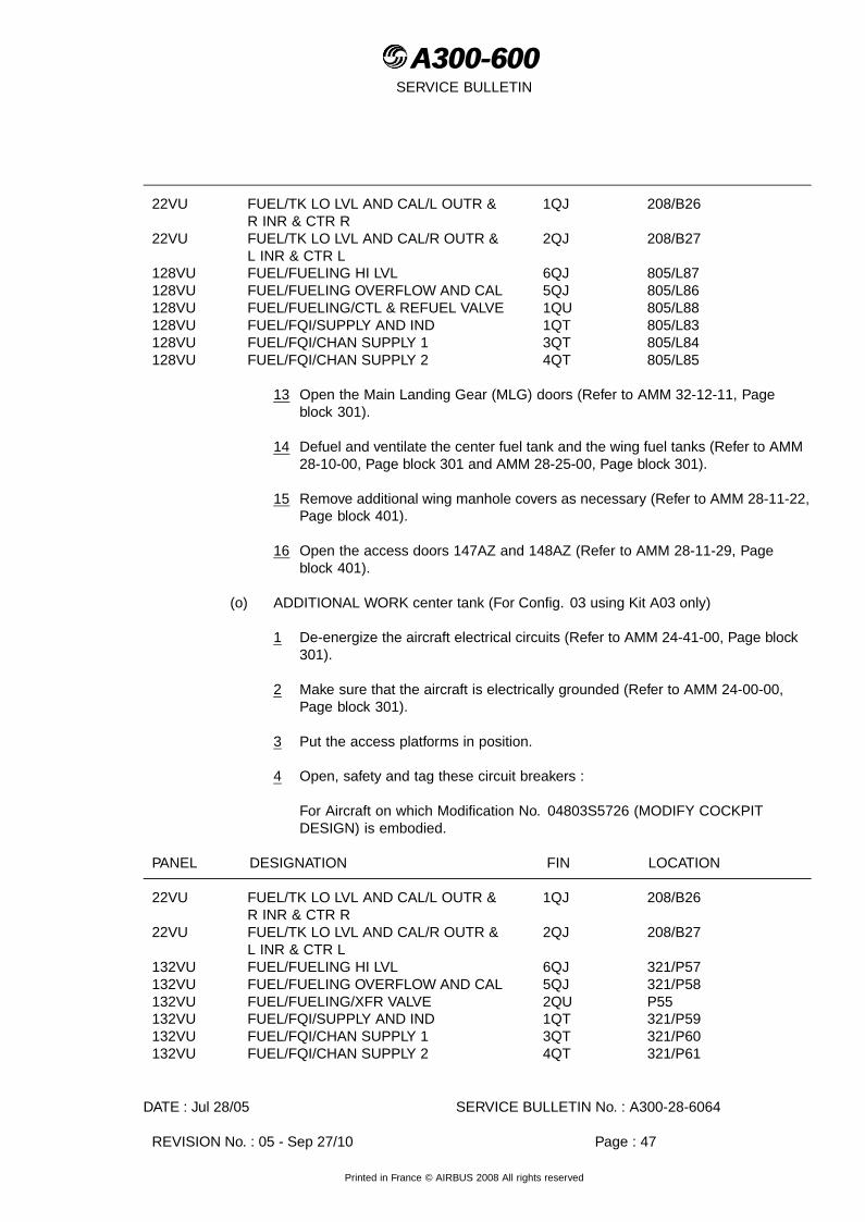
A300-600A300-600SERVICE BULLETIN
22VU FUEL/TK LO LVL AND CAL/L OUTR &R INR & CTR R
1QJ 208/B26
22VU FUEL/TK LO LVL AND CAL/R OUTR &L INR & CTR L
2QJ 208/B27
128VU FUEL/FUELING HI LVL 6QJ 805/L87128VU FUEL/FUELING OVERFLOW AND CAL 5QJ 805/L86128VU FUEL/FUELING/CTL & REFUEL VALVE 1QU 805/L88128VU FUEL/FQI/SUPPLY AND IND 1QT 805/L83128VU FUEL/FQI/CHAN SUPPLY 1 3QT 805/L84128VU FUEL/FQI/CHAN SUPPLY 2 4QT 805/L85
13 Open the Main Landing Gear (MLG) doors (Refer to AMM 32-12-11, Pageblock 301).
14 Defuel and ventilate the center fuel tank and the wing fuel tanks (Refer to AMM28-10-00, Page block 301 and AMM 28-25-00, Page block 301).
15 Remove additional wing manhole covers as necessary (Refer to AMM 28-11-22,Page block 401).
16 Open the access doors 147AZ and 148AZ (Refer to AMM 28-11-29, Pageblock 401).
(o) ADDITIONAL WORK center tank (For Config. 03 using Kit A03 only)
1 De-energize the aircraft electrical circuits (Refer to AMM 24-41-00, Page block301).
2 Make sure that the aircraft is electrically grounded (Refer to AMM 24-00-00,Page block 301).
3 Put the access platforms in position.
4 Open, safety and tag these circuit breakers :
For Aircraft on which Modification No. 04803S5726 (MODIFY COCKPITDESIGN) is embodied.
PANEL DESIGNATION FIN LOCATION
22VU FUEL/TK LO LVL AND CAL/L OUTR &R INR & CTR R
1QJ 208/B26
22VU FUEL/TK LO LVL AND CAL/R OUTR &L INR & CTR L
2QJ 208/B27
132VU FUEL/FUELING HI LVL 6QJ 321/P57132VU FUEL/FUELING OVERFLOW AND CAL 5QJ 321/P58132VU FUEL/FUELING/XFR VALVE 2QU P55132VU FUEL/FQI/SUPPLY AND IND 1QT 321/P59132VU FUEL/FQI/CHAN SUPPLY 1 3QT 321/P60132VU FUEL/FQI/CHAN SUPPLY 2 4QT 321/P61
DATE : Jul 28/05 SERVICE BULLETIN No. : A300-28-6064
REVISION No. : 05 - Sep 27/10 Page : 47
Printed in France © AIRBUS 2008 All rights reserved

A300-600A300-600SERVICE BULLETIN
or
PANEL DESIGNATION FIN LOCATION
22VU FUEL/TK LO LVL/L OUTR & R INR &CTR R
1QJ 208/B26
22VU FUEL/TK LO LVL/R OUTR & L INR &CTR L
2QJ 208/B27
132VU FUEL/FUELING HI LVL 6QJ 321/P57132VU FUEL/FUELING OVERFLOW AND CAL 5QJ 321/P58132VU FUEL/FUELING/XFR VALVE 2QU P55132VU FUEL/FQI/SUPPLY AND IND 1QT 321/P59132VU FUEL/FQI/CHAN SUPPLY 1 3QT 321/P60132VU FUEL/FQI/CHAN SUPPLY 2 4QT 321/P61
For Aircraft on which Modification No. 04803S5726 (MODIFY COCKPITDESIGN) is not embodied.
PANEL DESIGNATION FIN LOCATION
22VU FUEL/TK LO LVL/L OUTR & R INR &CTR R
1QJ 208/B26
22VU FUEL/TK LO LVL OUTR & L INR & CTR L 2QJ 208/B27128VU FUEL/FUELING HI LVL 6QJ 805/L87128VU FUEL/FUELING OVERFLOW 5QJ 805/L86128VU FUEL/FUELING/TRANSFER VALVE 2QU P55128VU FUEL/FQI/SUPPLY AND IND 1QT 805/L83128VU FUEL/FQI/CHAN SUPPLY 1 3QT 805/L84128VU FUEL/FQI/CHAN SUPPLY 2 4QT 805/L85
5 Open the Main Landing Gear (MLG) doors (Refer to AMM 32-12-11, Pageblock 301).
6 Defuel and ventilate the center fuel tank (Refer to AMM 28-10-00, Page block301 and AMM 28-25-00, Page block 301).
7 Open the access doors 147AZ and 148AZ (Refer to AMM 28-11-29, Pageblock 401).
(p) ADDITIONAL WORK on the wing tanks (For Config. 07 only) (Introduced by Rev 04)
1 De-energize the aircraft electrical circuits (Refer to AMM 24-41-00, Page block301).
2 Make sure that the aircraft is electrically grounded (Refer to AMM 24-00-00,Page block 301).
WARNING : MAKE SURE THAT PERSONNEL AND EQUIPMENT ARE CLEAROF THE TRAVEL RANGES OF THE SLATS/FLAPS.
3 Fully extend the slats (Refer to AMM 27-80-00, Page block 301).
4 Put access platforms in position as necessary.
DATE : Jul 28/05 SERVICE BULLETIN No. : A300-28-6064
REVISION No. : 05 - Sep 27/10 Page : 48
Printed in France © AIRBUS 2008 All rights reserved

A300-600A300-600SERVICE BULLETIN
5 Open, safety and tag these circuit breakers :
For Aircraft on which Modification No. 04803S5726 (MODIFY COCKPITDESIGN) is embodied.
PANEL DESIGNATION FIN LOCATION
22VU FUEL/TK LO LVL AND CAL/L OUTR &R INR & CTR R
1QJ 208/B26
22VU FUEL/TK LO LVL AND CAL/R OUTR &L INR & CTR L
2QJ 208/B27
132VU FUEL/FUELING HI LVL 6QJ 321/P57132VU FUEL/FUELING OVERFLOW AND CAL 5QJ 321/P58132VU FUEL/FUELING/XFR VALVE 2QU P55132VU FUEL/FQI/SUPPLY AND IND 1QT 321/P59132VU FUEL/FQI/CHAN SUPPLY 1 3QT 321/P60132VU FUEL/FQI/CHAN SUPPLY 2 4QT 321/P61
or
PANEL DESIGNATION FIN LOCATION
22VU FUEL/TK LO LVL/L OUTR & R INR &CTR R
1QJ 208/B26
22VU FUEL/TK LO LVL/R OUTR & L INR &CTR L
2QJ 208/B27
132VU FUEL/FUELING HI LVL 6QJ 321/P57132VU FUEL/FUELING OVERFLOW AND CAL 5QJ 321/P58132VU FUEL/FUELING/XFR VALVE 2QU P55132VU FUEL/FQI/SUPPLY AND IND 1QT 321/P59132VU FUEL/FQI/CHAN SUPPLY 1 3QT 321/P60132VU FUEL/FQI/CHAN SUPPLY 2 4QT 321/P61
For Aircraft on which Modification No. 04803S5726 (MODIFY COCKPITDESIGN) is not embodied.
PANEL DESIGNATION FIN LOCATION
22VU FUEL/TK LO LVL/L OUTR & R INR &CTR R
1QJ 208/B26
22VU FUEL/TK LO LVL/R OUTR & L INR &CTR L
2QJ 208/B27
128VU FUEL/FUELING HI LVL 6QJ 805/L87128VU FUEL/FUELING OVERFLOW 5QJ 805/L86128VU FUEL/FUELING/TRANSFER VALVE 2QU P55128VU FUEL/FQI/SUPPLY AND IND 1QT 805/L83128VU FUEL/FQI/CHAN SUPPLY 1 3QT 805/L84128VU FUEL/FQI/CHAN SUPPLY 2 4QT 805/L85
6 Defuel and ventilate the wing fuel tanks (Refer to AMM 28-25-00, Page block301).
DATE : Jul 28/05 SERVICE BULLETIN No. : A300-28-6064
REVISION No. : 05 - Sep 27/10 Page : 49
Printed in France © AIRBUS 2008 All rights reserved

A300-600A300-600SERVICE BULLETIN
7 Remove wing manhole covers as necessary (Refer to AMM 28-11-22, Pageblock 401).
(2) Standard Practices
(a) For access to the slat track canisters and screw-jack canisters (LH and RH wings),refer to AMM 57-20-43, Page block 401.
(b) For wing access panels/doors, refer to AMM 06-41-57, Page block 001.
(c) For the removal and installation of fasteners, refer to SRM 51-40-20.
(d) Cut rivets to the applicable length.
(e) For fastener hole and drill information, refer to SRM 51-40-44.
(f) For alternative fasteners, refer to SRM 51-40-30.
(g) For applicable torque values of fasteners, refer to SRM 51-43-00.
(h) For general sealant repair, refer to SRM 51-76-10.
(i) For the repair of integral tank sealing, refer to SRM 51-76-20.
(j) For the repair of paint coatings, refer to SRM 51-75-10.
(k) For the specification of material numbers (Mat.No.), refer to the CML.
(l) Clean the modification areas with cleaning agent (Mat. No. 11-026)as necessary.
(m) For the installation of the new bonding leads and new bonding positions in the wingsfuel tanks and the center fuel, refer to AMM 20-28-11, Page block 001 for:
- the preparation of the bonding positions.
- the installation of bonding leads, clamps and the installation of bolts as bondingbolts.
- the electrical-bonding resistance checks of the bonding positions.
- the application of protective coating to bonding items.
B. MODIFICATION
(1) Kit 286064A01R05, Kit 286064A02R02 and Kit 286064A03R00
(a) Check the bonding points in the center tank.
NOTE : In Fuel Center Tank, the modification consists in :- Checking the bonding points identified as potentially non conform, Refer to
Figure 1, Sheet 1.For each point identified check the presence of blue coat :
DATE : Jul 28/05 SERVICE BULLETIN No. : A300-28-6064
REVISION No. : 05 - Sep 27/10 Page : 50
Printed in France © AIRBUS 2008 All rights reserved

A300-600A300-600SERVICE BULLETIN
- If blue coat present, no further action.- If no blue coat then :
Measure the electrical resistance between part and the structure, (Referto AMM 20-28-11, Page block 001).
- If the ohmic resistance <10mhm, apply the blue coat.- If the ohmic resistance >10mhm, do the bonding, (Refer to AMM
20-28-11, Page block 001).
1 Check the bonding points Items 1 thru 5 at FR44.
Refer to Figure 1, Sheet 1, (General location)
Refer to Figure 2, Sheets 1 thru 6, (Detailed location)
Refer to Figure 3, Sheet 1, (Result table)
2 Check the bonding points Items 6 thru 24 at FR47.
Refer to Figure 1, Sheet 1, (General location)
Refer to Figure 4, Sheets 1 thru 17, (Detailed location)
Refer to Figure 5, Sheet 1, (Result table)
3 Check the bonding points Items 25 thru 29 on the rib 1 (LH side).
Refer to Figure 1, Sheet 1, (General location)
Refer to Figure 6, Sheets 1 thru 3, (Detailed location)
Refer to Figure 7, Sheet 1, (Result table)
4 Check the bonding points Items 30 thru 44 on the intrados panel.
Refer to Figure 1, Sheet 1, (General location)
Refer to Figure 8, Sheets 1 thru 10, (Detailed location)
Refer to Figure 9, Sheet 1, (Result table)
5 Check the bonding points Items 45 thru 51 on the rib 1 (RH side).
Refer to Figure 1, Sheet 1, (General location)
Refer to Figure 10, Sheets 1 thru 6, (Detailed location)
Refer to Figure 11, Sheet 1, (Result table)
6 Check the bonding points Items 52 thru 78 on the extrados panel.
Refer to Figure 1, Sheet 1, (General location)
DATE : Jul 28/05 SERVICE BULLETIN No. : A300-28-6064
REVISION No. : 05 - Sep 27/10 Page : 51
Printed in France © AIRBUS 2008 All rights reserved

A300-600A300-600SERVICE BULLETIN
Refer to Figure 12, Sheets 1 thru 8, (Detailed location)
Refer to Figure 13, Sheet 1, (Result table)
(2) Kit 286064A01R05
(a) Modify or install the bonding points.
1 Modify the refueling pipes on LH side between FR44 and FR47, valid for aircrafton which Mod. No. 04801H5078 (FUEL - INSTALL TRIM TANK SYSTEM) isembodied.Refer to Figure 14 Sheets 1 thru 3
a Remove :
1 screw Item (285) Retain1 washer Item (3) Retain
Disengage the bonding lead item (281) without complete removal.
- On the sleeve item (268), do a stripping to the dimensions given in thefigure 14 sheet 3
- Install on the sleeve item (268) :
1 Bonding Lead E0088-10-80 Item 151 Nut NAS1726-3E Item 51 Clamp AN735D40 Item 131 Screw NAS1801-3-8 Item 14
b Install the bonding leads item (281) and 15 with :1 Screw Item (285)1 Washer Item (3)
NOTE : Items (3) and (285) were retained at removal.
c For aircraft on which modification No. 06549 (FUEL - TRIM TANK SYSTEM- EMBODY ANTI-MODIFICATION TO ALLOW CHANGE FROM "WET" TO"DRY") is not embodied, do a stripping on the sleeve item (268) to thedimensions given in the figure 14 sheet 3 detail E.
- Install on the sleeve item (268) :
1 Bonding Lead E0088-10-80 Item 151 Nut NAS1726-3E Item 51 Clamp AN735D40 Item 131 Screw NAS1801-3-8 Item 14
- Remove :
1 Screw Item (220) Retain1 Nut Item (4) Discard1 Screw Item (285) Retain1 Washer Item (3) Retain
DATE : Jul 28/05 SERVICE BULLETIN No. : A300-28-6064
REVISION No. : 05 - Sep 27/10 Page : 52
Printed in France © AIRBUS 2008 All rights reserved

A300-600A300-600SERVICE BULLETIN
- Install the bonding lead Item 15 with :
1 Screw Item (285)1 Washer Item (3)
NOTE : Item (3) and (285) were retained at removal.
- Install :
1 Screw Item (220)1 Nut NAS1726-4E Item 4
NOTE : Item (220) was retained at removal.
2 Modify the tube item (283) from TTS pipes, valid for aircraft on which Mod. No.04801H5078 (FUEL - INSTALL TRIM TANK SYSTEM) is embodied.Refer to Figure 15 Sheets 1 thru 3
a Remove :
Refer to Figure 15 Sheets 2 and 3
1 Screw Item (285) Retain1 Washer Item (3) Retain
Disengage the bonding lead item (284) without complete removal.
b On the sleeve item (268), do a stripping to the dimensions given in thefigure 15 sheet 3
c Install on the sleeve item (268) :
1 Bonding Lead E0088-10-80 Item 151 Nut NAS1726-3E Item 51 Clamp AN735D40 Item 131 Screw NAS1801-3-8 Item 14
d Install the bonding leads item (284) and 15 with :
1 Screw Item (285)1 Washer Item (3)
NOTE : Items (3) and (285) were retained at removal.
3 Modify the sleeves item (268), valid for aircraft on which Mod. No. 04801H5078(FUEL - INSTALL TRIM TANK SYSTEM) is embodied.Refer to Figure 15 Sheets 1, 4 thru 6
a Remove :
Refer to Figure 15 Sheet 4
2 Screw Item (2) Retain
DATE : Jul 28/05 SERVICE BULLETIN No. : A300-28-6064
REVISION No. : 05 - Sep 27/10 Page : 53
Printed in France © AIRBUS 2008 All rights reserved

A300-600A300-600SERVICE BULLETIN
2 Washer Item (3) Retain1 Screw Item (269) Retain1 Nut Item (4) Discard
- Disengage the bonding lead item (16).
b On the sleeves item (268), do strippings to the dimensions given in thefigure 15 sheet 6.
c On the tee pipe, do strippings to the dimensions given in the figure 15sheet 6.
d Install on the sleeves item (268) :
Refer to Figure 15 Sheet 6
2 Bonding Lead E0088-10-160 Item 162 Clamp AN735D40 Item 132 Nut NAS1726-3E Item 52 Screw NAS1801-3-8 Item 14
e Put the bonding leads Item (16) and Item 16 in position on the tee pipe.
Refer to Figure 15 Sheet 5
f Install :
2 Screw Item (2)2 Washer Item (3)1 Screw Item (269)1 Nut NAS1726-4E Item 4
NOTE : Items (2), (3) and (269) were retained at removal.
4 Modify the sleeves item (268) from TTS pipes, valid for aircraft on which Mod.No. 04801H5078 (FUEL - INSTALL TRIM TANK SYSTEM) is embodied.Refer to Figure 15 Sheets 7 and 8
a On the sleeves item (268), do strippings to the dimensions given in thefigure 15 sheet 8.
b Install on the sleeves item (268) :
Refer to Figure 15 Sheet 8
3 Bonding Lead E0088-10-80 Item 153 Clamp AN735D40 Item 133 Nut NAS1726-3E Item 53 Screw NAS1801-3-8 Item 14
c Attach the bonding lead Item 15 on the flange of tee pipe :
Refer to Figure 15 Sheet 7
DATE : Jul 28/05 SERVICE BULLETIN No. : A300-28-6064
REVISION No. : 05 - Sep 27/10 Page : 54
Printed in France © AIRBUS 2008 All rights reserved

A300-600A300-600SERVICE BULLETIN
1 Bolt NAS1303-2 Item 171 Washer NAS1149D0316H Item 20
d Remove from the tee pipe :
Refer to Figure 15 Sheet 8
2 Screw Item (569) Retain2 Nut Item (5) Discard
e Put the bonding leads Item 15 in position on the tee pipe.
Refer to Figure 15 Sheets 7 and 8
f Install on the tee pipe :Refer to Figure 15 Sheet 8
2 Screw Item (569)2 Nut NAS1726-3E Item 5
NOTE : Item (569) was retained at removal.
5 Modify the feed pipes, valid for aircraft on which Mod. No. 04801H5078 (FUEL -INSTALL TRIM TANK SYSTEM) is embodied.Refer to Figure 16 Sheets 1 thru 3
a Remove from LH side :
1 Screw Item (285) Retain1 Washer Item (413) Retain
b On the tube item (333), do a stripping to the dimensions given in thefigure 16 sheet 2.
c Install :
1 Bonding Lead E0088-10-80 Item 151 Clamp NSA5519-2B Item 81 Bolt NAS1303-3 Item 21 Nut NAS1726-3E Item 51 Screw Item (285)1 Washer Item (413)
NOTE : Items (285) and (413) were retained at removal.
d Remove from RH side :
1 Screw Item (285) Retain1 Washer Item (413) Retain1 Nut Item (5) Discard
Disengage the bonding lead without complete removal.
DATE : Jul 28/05 SERVICE BULLETIN No. : A300-28-6064
REVISION No. : 05 - Sep 27/10 Page : 55
Printed in France © AIRBUS 2008 All rights reserved

A300-600A300-600SERVICE BULLETIN
e On the tube item (334), do a stripping to the dimensions given in thefigure 16 sheet 3.
f Install :
1 Bonding Lead E0088-10-160 Item 161 Clamp NSA5519-2B Item 81 Bolt NAS1303-3 Item 21 Nut NAS1726-3E Item 5
Put the bonding leads Item in position with :
1 Screw Item (285)1 Washer Item (413)1 Nut NAS1726-3E Item 5
NOTE : Items (285) and (413) were retained at removal.
6 Install new bonding lead on the cross feed pipe between FR46 and FR47Refer to Figure 17 Sheets 1 and 2
a Remove :
1 Screw Item (2) Retain1 Washer Item (3) Retain
- Disengage the bonding lead without complete removal.
b On the tube, do a stripping to the dimensions given in the figure 17 sheet 2.
c Install :
1 Nut NAS1726-3E Item 52 Bolt NAS1303-2 Item 172 Washer NAS1149F0332P Item 31 Bonding Lead E0088-10-125 Item 71 Clamp NSA5519-2B Item 8
- Install the bonding leads with :
1 Screw Item (2)1 Washer Item (3)
NOTE : Items (2) and (3) were retained at removal.
(3) Kit 286064A02R02
(a) Modify or install the bonding points.
1 Modify the refueling pipes on LH side between FR44 and FR47.Refer to Figure 18 Sheets 1 thru 3
a Remove :
DATE : Jul 28/05 SERVICE BULLETIN No. : A300-28-6064
REVISION No. : 05 - Sep 27/10 Page : 56
Printed in France © AIRBUS 2008 All rights reserved

A300-600A300-600SERVICE BULLETIN
1 Screw Item (285) Retain1 Washer Item (3) Retain
Disengage the bonding lead item (281) without complete removal.
- On the sleeve item (268), do a stripping to the dimensions given in thefigure 18 sheet 3
- Install on the sleeve item (268) :
1 Bonding Lead E0088-10-80 Item 151 Nut NAS1726-3E Item 51 Clamp AN735D40 Item 131 Screw NAS1801-3-8 Item 14
b Install the bonding leads item (281) and 15 with :1 Screw Item (285)1 Washer Item (3)
NOTE : Items (3) and (285) were retained at removal.
c For aircraft on which modification No. 06549 (FUEL - TRIM TANK SYSTEM- EMBODY ANTI-MODIFICATION TO ALLOW CHANGE FROM "WET" TO"DRY") is not embodied, do a stripping on the sleeve item (268) to thedimensions given in the figure 18 sheet 3 detail E.
- Install on the sleeve item (268) :
1 Bonding Lead E0088-10-80 Item 151 Nut NAS1726-3E Item 51 Clamp AN735D40 Item 131 Screw NAS1801-3-8 Item 14
- Remove :
1 Screw Item (220) Retain1 Nut Item (4) Discard1 Screw Item (285) Retain1 Washer Item (3) Retain
- Install the bonding lead Item 15 with :
1 Screw Item (285)1 Washer Item (3)
NOTE : Item (3) and (285) were retained at removal.
- Install :
1 Screw Item (220)1 Nut NAS1726-4E Item 4
NOTE : Item (220) was retained at removal.
2 Modify the tube item (283) from TTS pipes.
DATE : Jul 28/05 SERVICE BULLETIN No. : A300-28-6064
REVISION No. : 05 - Sep 27/10 Page : 57
Printed in France © AIRBUS 2008 All rights reserved
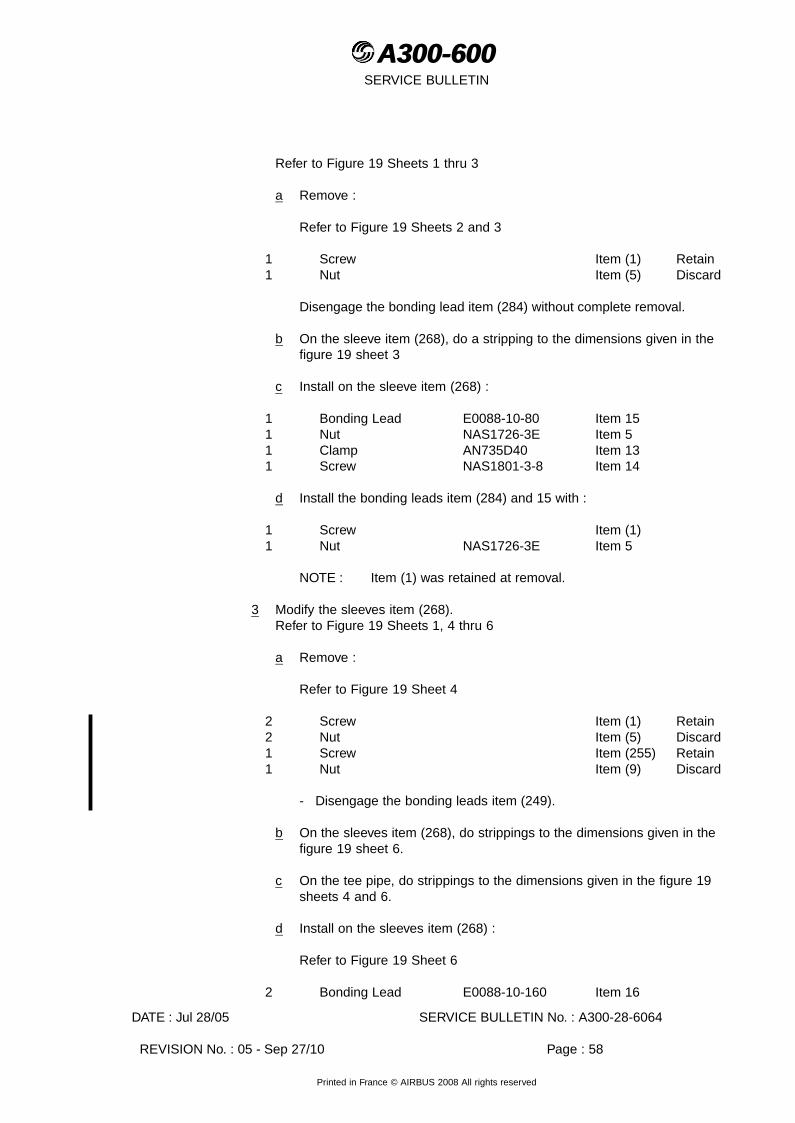
A300-600A300-600SERVICE BULLETIN
Refer to Figure 19 Sheets 1 thru 3
a Remove :
Refer to Figure 19 Sheets 2 and 3
1 Screw Item (1) Retain1 Nut Item (5) Discard
Disengage the bonding lead item (284) without complete removal.
b On the sleeve item (268), do a stripping to the dimensions given in thefigure 19 sheet 3
c Install on the sleeve item (268) :
1 Bonding Lead E0088-10-80 Item 151 Nut NAS1726-3E Item 51 Clamp AN735D40 Item 131 Screw NAS1801-3-8 Item 14
d Install the bonding leads item (284) and 15 with :
1 Screw Item (1)1 Nut NAS1726-3E Item 5
NOTE : Item (1) was retained at removal.
3 Modify the sleeves item (268).Refer to Figure 19 Sheets 1, 4 thru 6
a Remove :
Refer to Figure 19 Sheet 4
2 Screw Item (1) Retain2 Nut Item (5) Discard1 Screw Item (255) Retain1 Nut Item (9) Discard
- Disengage the bonding leads item (249).
b On the sleeves item (268), do strippings to the dimensions given in thefigure 19 sheet 6.
c On the tee pipe, do strippings to the dimensions given in the figure 19sheets 4 and 6.
d Install on the sleeves item (268) :
Refer to Figure 19 Sheet 6
2 Bonding Lead E0088-10-160 Item 16
DATE : Jul 28/05 SERVICE BULLETIN No. : A300-28-6064
REVISION No. : 05 - Sep 27/10 Page : 58
Printed in France © AIRBUS 2008 All rights reserved
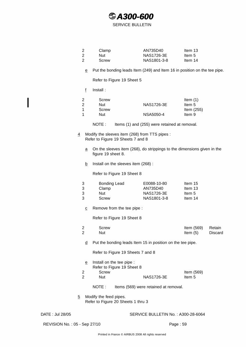
A300-600A300-600SERVICE BULLETIN
2 Clamp AN735D40 Item 132 Nut NAS1726-3E Item 52 Screw NAS1801-3-8 Item 14
e Put the bonding leads Item (249) and Item 16 in position on the tee pipe.
Refer to Figure 19 Sheet 5
f Install :
2 Screw Item (1)2 Nut NAS1726-3E Item 51 Screw Item (255)1 Nut NSA5050-4 Item 9
NOTE : Items (1) and (255) were retained at removal.
4 Modify the sleeves item (268) from TTS pipes :Refer to Figure 19 Sheets 7 and 8
a On the sleeves item (268), do strippings to the dimensions given in thefigure 19 sheet 8.
b Install on the sleeves item (268) :
Refer to Figure 19 Sheet 8
3 Bonding Lead E0088-10-80 Item 153 Clamp AN735D40 Item 133 Nut NAS1726-3E Item 53 Screw NAS1801-3-8 Item 14
c Remove from the tee pipe :
Refer to Figure 19 Sheet 8
2 Screw Item (569) Retain2 Nut Item (5) Discard
d Put the bonding leads Item 15 in position on the tee pipe.
Refer to Figure 19 Sheets 7 and 8
e Install on the tee pipe :Refer to Figure 19 Sheet 8
2 Screw Item (569)2 Nut NAS1726-3E Item 5
NOTE : Items (569) were retained at removal.
5 Modify the feed pipes.Refer to Figure 20 Sheets 1 thru 3
DATE : Jul 28/05 SERVICE BULLETIN No. : A300-28-6064
REVISION No. : 05 - Sep 27/10 Page : 59
Printed in France © AIRBUS 2008 All rights reserved
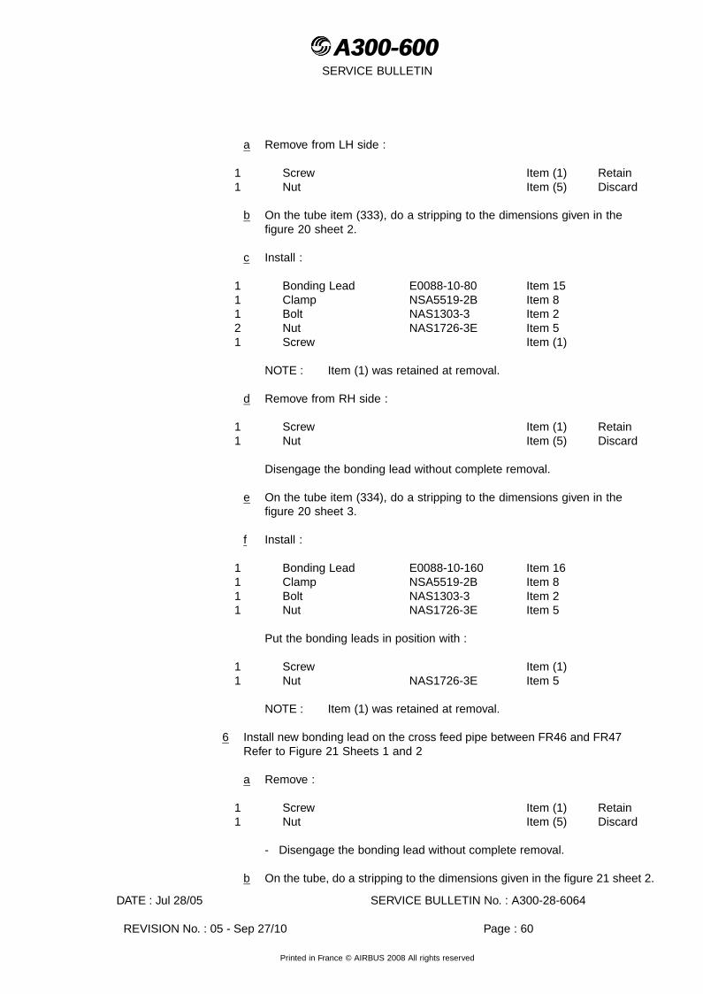
A300-600A300-600SERVICE BULLETIN
a Remove from LH side :
1 Screw Item (1) Retain1 Nut Item (5) Discard
b On the tube item (333), do a stripping to the dimensions given in thefigure 20 sheet 2.
c Install :
1 Bonding Lead E0088-10-80 Item 151 Clamp NSA5519-2B Item 81 Bolt NAS1303-3 Item 22 Nut NAS1726-3E Item 51 Screw Item (1)
NOTE : Item (1) was retained at removal.
d Remove from RH side :
1 Screw Item (1) Retain1 Nut Item (5) Discard
Disengage the bonding lead without complete removal.
e On the tube item (334), do a stripping to the dimensions given in thefigure 20 sheet 3.
f Install :
1 Bonding Lead E0088-10-160 Item 161 Clamp NSA5519-2B Item 81 Bolt NAS1303-3 Item 21 Nut NAS1726-3E Item 5
Put the bonding leads in position with :
1 Screw Item (1)1 Nut NAS1726-3E Item 5
NOTE : Item (1) was retained at removal.
6 Install new bonding lead on the cross feed pipe between FR46 and FR47Refer to Figure 21 Sheets 1 and 2
a Remove :
1 Screw Item (1) Retain1 Nut Item (5) Discard
- Disengage the bonding lead without complete removal.
b On the tube, do a stripping to the dimensions given in the figure 21 sheet 2.
DATE : Jul 28/05 SERVICE BULLETIN No. : A300-28-6064
REVISION No. : 05 - Sep 27/10 Page : 60
Printed in France © AIRBUS 2008 All rights reserved

A300-600A300-600SERVICE BULLETIN
c Install :
1 Nut NAS1726-3E Item 51 Bolt NAS1303-2 Item 171 Washer NAS1149F0332P Item 31 Bonding Lead E0088-10-125 Item 71 Clamp NSA5519-2B Item 8
- Install the bonding leads with :
1 Screw Item (1)1 Nut NAS1726-3E Item 5
NOTE : Item (1) was retained at removal.
(4) Kit 286064A03R00
(a) Install the bonding points.
1 Remove :2 Screw Item (206) Retain2 Washer Item (260) Retain
2 On the blanking plates item (310), do a stripping to the dimension given in thefigure 22, sheets 2 and 3.
3 Temporarily install the bonding lead item 10 on the angle item 12.
4 Temporarily install the angle item 12 on the structure as shown in the figure22, sheets 2 and 3.
5 Drill the structure to match the holes of the angle item 12 at the dimensionsgiven in the figure 22, sheet 3.
6 Install :2 Angle A9242127720000 Item 12
with
4 Rivet ASNA2050DCJ3215 Item 11
7 Install :2 Screw Item (206)2 Washer Item (260)2 Bonding Lead E0088-10-200 Item 102 Nut NAS1726-3E Item 52 Bolt NAS1303-3 Item 22 Washer NAS1149F0332P Item 3
NOTE : Items (206) and (260) were retained at removal.
(5) Wings Fuel Tanks
DATE : Jul 28/05 SERVICE BULLETIN No. : A300-28-6064
REVISION No. : 05 - Sep 27/10 Page : 61
Printed in France © AIRBUS 2008 All rights reserved

A300-600A300-600SERVICE BULLETIN
(a) The Tables that follow list all the equipment in the wings fuel tanks that are to bemodified for electrical bonding. The work is listed by rib bay. The detailed workstepsfor each rib bay is given in para. (6) thru (25) for pre Mod. 12226 aircraft andpara. (26) for Post Mod. 12226 aircraft.
Paragraph (27) refers to the ADDITIONAL WORK (Introduced by Rev 01) that isnecessary if this Service Bulletin has been embodied on aircraft at original issue,which were not Config. 05 aircraft.
The worksteps given are for the LH wing. The worksteps for the RH wing are thesame unless otherwise stated.
TABLE 1 - PRE. MOD. 12226 AIRCRAFT
LH AND RH WING
APPLICABLE RIB BAY
EQUIPMENT TOBE ELECTRICALLYBONDED
REFERENCEDFIGURES
APPLICABLE KIT
Rib Bay 1-2 Water Drain Valves.
Water Scavenge Pipes(Config. 03 aircraft).
MLI.
Fuel Feed Pipe.
Low Fuel PressureSwitches.
Fuel Booster Pumps.
Fuel Booster Pumps(Config. 06 aircraft).
Diffuser.
Fuel Level sensor.
Figure 23, Sheet 1
Figure 24, Sheet 1
Figure 25, Sheet 1
Figure 26, Sheet 1
Figure 27, Sheet 1
Figure 28, Sheet 1
Figure 29, Sheet 2
Figure 30, Sheet 2
Kit B01R05 all aircraft.
For Config. 03 aircraftKit B22R05.
For Config. 06 aircraftKit B23R01.
Rib Bay 2-3 Diffuser.
Calibration Sensor(Config. 04 aircraft)
Figure 29, Sheet 1
Figure 30, Sheet 1
Kit B01R05 all aircraft.
For Config. 04 aircraftKit B21R01.
Rib Bay 5-6 Slat Track Canister 3. Figure 31, Sheet 1,Sheet 2
Kit B03R03 all aircraftand Kit B02R02 orB26R01 for Config. 02aircraft
Rib Bay 8-9 Slat Track Canister 4.
MLI.
Figure 32, Sheet 1
Figure 31, Sheet 2
Figure 25, Sheet 1
Kit B04R03 all aircraftand Kit B02R02 orB26R01 for Config. 02aircraft.
DATE : Jul 28/05 SERVICE BULLETIN No. : A300-28-6064
REVISION No. : 05 - Sep 27/10 Page : 62
Printed in France © AIRBUS 2008 All rights reserved
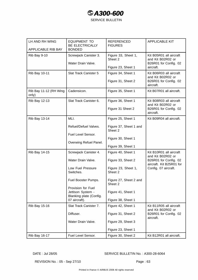
A300-600A300-600SERVICE BULLETIN
LH AND RH WING
APPLICABLE RIB BAY
EQUIPMENT TOBE ELECTRICALLYBONDED
REFERENCEDFIGURES
APPLICABLE KIT
Rib Bay 9-10 Screwjack Canister 3.
Water Drain Valve.
Figure 33, Sheet 1,Sheet 2
Figure 23, Sheet 1
Kit B05R01 all aircraftand Kit B02R02 orB26R01 for Config. 02aircraft.
Rib Bay 10-11 Slat Track Canister 5 Figure 34, Sheet 1
Figure 31, Sheet 2
Kit B06R03 all aircraftand Kit B02R02 orB26R01 for Config. 02aircraft.
Rib Bay 11-12 (RH Wingonly)
Cadensicon. Figure 35, Sheet 1 Kit B07R01 all aircraft.
Rib Bay 12-13 Slat Track Canister 6. Figure 36, Sheet 1
Figure 31 Sheet 2
Kit B08R03 all aircraftand Kit B02R02 orB26R01 for Config. 02aircraft.
Rib Bay 13-14 MLI.
Refuel/Defuel Valves.
Fuel Level Sensor.
Overwing Refuel Panel.
Figure 25, Sheet 1
Figure 37, Sheet 1 andSheet 2
Figure 30, Sheet 1
Figure 39, Sheet 1
Kit B09R04 all aircraft.
Rib Bay 14-15 Screwjack Canister 4.
Water Drain Valve.
Low Fuel PressureSwitches.
Fuel Booster Pumps.
Provision for FuelJettison System -Blanking plate (Config.07 aircraft).
Figure 40, Sheet 1
Figure 33, Sheet 2
Figure 23, Sheet 1,Sheet 2
Figure 27, Sheet 2 andSheet 2
Figure 41, Sheet 1
Figure 38, Sheet 1
Kit B10R01 all aircraftand Kit B02R02 orB26R01 for Config. 02aircraft. Kit B25R01 forConfig. 07 aircraft.
Rib Bay 15-16 Slat Track Canister 7.
Diffuser.
Water Drain Valve.
Figure 42, Sheet 1
Figure 31, Sheet 2
Figure 29, Sheet 3
Figure 23, Sheet 1
Kit B11R05 all aircraftand Kit B02R02 orB26R01 for Config. 02aircraft.
Rib Bay 16-17 Fuel Level Sensor. Figure 30, Sheet 2 Kit B12R01 all aircraft.
DATE : Jul 28/05 SERVICE BULLETIN No. : A300-28-6064
REVISION No. : 05 - Sep 27/10 Page : 63
Printed in France © AIRBUS 2008 All rights reserved

A300-600A300-600SERVICE BULLETIN
LH AND RH WING
APPLICABLE RIB BAY
EQUIPMENT TOBE ELECTRICALLYBONDED
REFERENCEDFIGURES
APPLICABLE KIT
Rib Bay 17-18 Provision for a FuelJettison System -Blanking Plates (Config.07 aircraft).
Figure 38, Sheet1 Kit B25R01 for Config.07 aircraft.
Rib Bay 18-19 Slat Track Canister 8. Figure 43, Sheet 1
Figure 31, Sheet 2
Kit B13R03 all aircraftand Kit B02R02 orB26R01 for Config 01and Config. 02 aircraft.
Rib Bay 20-21 Screwjack Canister 5.
MLI
Figure 44, Sheet 1
Figure 33, Sheet 2
Figure 25, Sheet 1
Kit B14R02 all aircraftand Kit B02R02 orB26R01 for Config. 02aircraft.
Rib Bay 21-22 Slat Track Canister 9. Figure 45, Sheet 1
Figure 31, Sheet 2
Kit B15R04 all aircraftand Kit B02R02 orB26R01 for Config 01and Config. 02 aircraft.
Rib Bay 24-25 Slat Track Canister 10 Figure 46, Sheet 1
Figure 31, Sheet 2
Kit B16R03 all aircraftand Kit B02R02 orB26R01 for Config. 01and Config. 02 aircraft.
Rib Bay 25-26 Fuel level Sensor Figure 30, Sheet 1 Kit B19R02 all aircraft.
Rib Bay 26-27 Screwjack Canister 6.
MLI.
Overwing Refuel Panel.
Figure 47, Sheet 1
Figure 25, Sheet 1
Figure 39, Sheet 1
Kit B17R01 all aircraftand Kit B27R01 orB28R01 for Config. 02aircraft.
Rib Bay 27-28 Slat Track Canister 11.
Water Drain.
Fuel Overflow Sensor.
Overpressure Protector.
Figure 48, Sheet 1
Figure 31, Sheet 2
Figure 23, Sheet 1
Figure 30, Sheet 4
Figure 49, Sheet 1
Kit B18R04 all aircraftand Kit B02R02 orB26R01 for Config. 01and Config. 02 aircraft.
CAUTION : DO NOT USE SELF SEALING NUTS AT ANY OF THE BONDING POINTS.
ADDITIONAL WORK (Introduced by Rev 01)
Rib Bay 13-14
Additional Work
Refuel/Defuel Valves LHWing
Figure 37, Sheet 1 andSheet 2
Kit B39R00
DATE : Jul 28/05 SERVICE BULLETIN No. : A300-28-6064
REVISION No. : 05 - Sep 27/10 Page : 64
Printed in France © AIRBUS 2008 All rights reserved

A300-600A300-600SERVICE BULLETIN
TABLE 2 - CONFIG 08 POST Mod. 12226 AIRCRAFT ONLY
LH and RH WING -APPLICABLE RIB BAY
EQUIPMENT TOBE ELECTRICALLYBONDED
REFERENCE FIGURES APPLICABLE KIT
Rib Bay 1-2 Water Drain Valves.
Water Scavenge Pipe.
MLI.
Fuel Feed Pipe SupportBracket.
Low Fuel PressureSwitches.
Fuel Booster PumpsCanisters.
Fuel Diffuser.
Low Level Fuel Sensor.
Figure 23, Sheet 1
Figure 24, Sheet 2
Figure 25, Sheet 1
Figure 26, Sheet 1
Figure 27, Sheet 1
Figure 28, Sheet 1
Figure 29, Sheet 4
Figure 30, Sheet 3
Kit B20R06
CAUTION : DO NOT USE SELF SEALING NUTS AT ANY OF THE BONDING POINTS.
(6) Rib Bay 1-2Kit 286064B01R05 all aircraftKit 286064B22R05 Config. 03 aircraftKit 286064B23R01 Config. 06 aircraft
(a) Forward Rib Bay Water Drain ValveKit 286064B01R05Refer to Figure 23, Sheet 1, Detail D
1 At the water drain valve, remove:
- one nut, Item (20), discard.
- one bolt, Item (19), retain.
2 At the base of the water drain valve prepare the bonding area. For the boltthrough the wing skin also prepare the countersink. Install:
- 1 retained bolt, Item (19).
1 Nut NSA5474-4K7 Item 20
(b) Aft Rib Bay Water Drain ValveKit 286064B01R05Refer to Figure 23, Sheet 1, Detail A
DATE : Jul 28/05 SERVICE BULLETIN No. : A300-28-6064
REVISION No. : 05 - Sep 27/10 Page : 65
Printed in France © AIRBUS 2008 All rights reserved

A300-600A300-600SERVICE BULLETIN
1 At the water drain valve, remove:
- one nut, Item (20), discard.
- one bolt, Item (19), retain.
2 At the water drain valve pipe prepare the bonding area and install:
1 Clamp AN742D6 Item 151 Lead E0088-41-160 Item 141 Bolt NSA5020-3-3 Item 171 Nut NSA5474-3K7 Item 16
3 At the base of the water drain valve prepare the bonding area. For the boltthrough the wing skin also prepare the countersink. Install:
- 1 retained bolt, Item (19).
- the other end of bonding lead, Item 14.
1 Nut NSA5474-4K7 Item 20
(c) Water Scavenge Pipe - Config. 03 aircraftKit 286064B22R05Refer to Figure 24, Sheet 1
1 At the pipe clamps (Refer to Detail A and Detail C), remove:
- five nuts, Item (16), discard.
- three bolts, Item (37), discard.
- two bolts, Item (82), discard.
- three clamps, Item (22), retain.
2 At the water drain-pipe support bracket (Refer to Detail B), remove:
- two nuts, Item (16), discard.
- one bolt, Item (37), discard.
- one bolt, Item (23), discard.
- one clamp, Item (22) retain.
If the support bracket is attached by rivets, remove one of the rivets and increasethe diameter of the hole to 4.826-4-877mm (0.1900-0.1920in.) to allow for theinstallation of a bolt.
3 On the support bracket and pipe clamp position (refer to Detail B) preparethe bonding area and install:
DATE : Jul 28/05 SERVICE BULLETIN No. : A300-28-6064
REVISION No. : 05 - Sep 27/10 Page : 66
Printed in France © AIRBUS 2008 All rights reserved

A300-600A300-600SERVICE BULLETIN
- 1 retained clamp, Item (22).
1 Bolt NAS1303-2 Item 371 Bolt NAS1303-8 Item 232 Nut NSA5474-3K7 Item 16
4 On the support brackets and pipe clamp positions (refer to Detail A and C)prepare the bonding areas and install:
- 3 retained clamps, Item (22).
2 Bolt NSA5480PN3-5 Item 823 Bolt NAS1303-2 Item 375 Nut NSA5474-3K7 Item 16
(d) MLIKit 286064B01R05Refer to Figure 25, Sheet 1, Detail B
1 At the base of the MLI, remove:
- one nut, Item (25), discard.
- the related bolt, Item (24), retain.
2 Prepare the bonding area and for the bolt that goes through the wing skin,prepare the countersink. Install:
- the retained bolt, Item (24)
1 Nut H19200C4 Item 25
(e) Fuel Feed Pipe SupportKit 286064B01R05Refer to Figure 26, Sheet 1
1 At the fuel pipe support bracket, upper section, remove:
- one nut, Item (16), discard.
- one bolt, Item (27), discard.
2 At the fuel pipe support bracket, lower section, remove:
- one nut, Item (16), discard.
- one bolt, Item (77), discard.
- one washer, Item (28), if installed, discard.
3 At the fuel pipe support bracket, upper section, prepare the bonding areaand install:
DATE : Jul 28/05 SERVICE BULLETIN No. : A300-28-6064
REVISION No. : 05 - Sep 27/10 Page : 67
Printed in France © AIRBUS 2008 All rights reserved

A300-600A300-600SERVICE BULLETIN
1 Bolt NSA5041VBV3-4 Item 271 Nut NSA5474-3K7 Item 16
4 At the fuel pipe support bracket, lower section, prepare the bonding area andinstall:
1 Bolt NSA5041VBV3-8 Item 771 Nut NSA5474-3K7 Item 16
and if applicable:
1 Washer AN960C10L Item 28
(f) Low Fuel Pressure SwitchesKit 286064B01R05Refer to Figure 27, Sheet 1
1 At each pressure switch attachment to the rear spar, remove:
- one nut, Item (16), discard.
- one bolt, Item (34), discard.
2 At the two pressure switch pipes prepare the bonding areas and install:
2 Clamp NSA5519-2B Item 352 Lead E0088-10-100 Item 382 Bolt NAS1303-2 Item 372 Nut NSA5474-3K7 Item 16
3 At the two pressure switches attachments to the rear spar prepare the bondingareas and attach the bonding leads, Item 38, with:
2 Bolt NSA5041VBV3-10 Item 342 Nut NSA5474-3K7 Item 16
4 Torque tighten the nuts, Item 16, to between 0.34-0.40 mdaN (30-35 lbf.in.).
(g) Fuel Booster Pumps Canisters - All AircraftKit 286064B01R05Refer to Figure 28, Sheet 1
1 At each canister flange (at the positions shown in the figure), remove:
- two bolts, Item (45), discard.
CAUTION : BOLTS THAT GO THROUGH THE FAIRING ARE NOT TO BE USEDAS BONDING BOLTS.
2 At the two canister flanges prepare the bonding areas and for the bolts throughthe wing skin prepare the countersinks only and install:
4 Bolt NSA5022-4-21 Item 45
DATE : Jul 28/05 SERVICE BULLETIN No. : A300-28-6064
REVISION No. : 05 - Sep 27/10 Page : 68
Printed in France © AIRBUS 2008 All rights reserved

A300-600A300-600SERVICE BULLETIN
3 At each of the canisters, at the fuel outlet flange (adjacent to the existing bondinglead, refer to Detail C) remove:
- one nut (20), discard.
- one bolt, Item (43), retain.
4 On the two pressure switch pipes prepare the bonding areas and install:
2 Clamp NSA5519-2B Item 352 Lead E0088-41-100 Item 392 Bolt NAS1303-2 Item 372 Nut NSA5474-3K7 Item 16
5 Torque tighten the bonding lead nuts, Item 16, to between 0.34-0.40 mdaN(30-35 lbf.in.).
6 At the two canisters, adjacent to the existing bonding leads, prepare the bondingareas and attach the bonding leads, Item 39, with:
- two retained bolts, Item (43).
2 Nut NSA5474-4K7 Item 20
7 Torque tighten the nuts, Item 20, to between 0.68-0.70 mdaN (60-70 lbf.in.).
(h) Fuel Booster Pump Config. 06 aircraftKit 286064B23R01Refer to Figure 28, Sheet 1
1 At the rear of the outboard canister, on the canister housing (refer to DetailB), remove:
- one bolt, Item (47), retain.
- one washer, Item (48), retain.
2 On the canister pipe prepare the bonding area and install:
1 Clamp NSA5519-4B Item 831 Lead E0088-10-100 Item 381 Bolt NSA5020-3-3 Item 171 Nut NSA5474-3K7 Item 16
3 Torque tighten the bonding lead nut, Item 16, to between 0.34-0.40 mdaN(30-35 lbf.in.).
4 Attach the bonding lead, Item 38, to the canister housing with:
- one retained bolt, Item (47).
- one retained washer, Item (48).
DATE : Jul 28/05 SERVICE BULLETIN No. : A300-28-6064
REVISION No. : 05 - Sep 27/10 Page : 69
Printed in France © AIRBUS 2008 All rights reserved

A300-600A300-600SERVICE BULLETIN
(i) DiffuserKit 286064B01R05Refer to Figure 29, Sheet 2, Detail B
1 At the diffuser, remove:
- one nut, Item (20), discard.
- one washer, Item (52), discard.
- two bolts, Item (46), discard.
- two washers, Item (53), discard.
2 At the support brackets attachment to the structure, remove:
- two nuts, Item (49), discard.
or
- two nuts, Item (4), discard.
NOTE : The bolts that attach the support brackets to the structure are aninterference fit through the wing skin and are therefore bonded,do not remove.
3 At the diffuser prepare the bonding areas and install:
2 Bolt NAS1304-3 Item 462 Washer AN960PD416 Item 531 Washer A2824028520000 Item 521 Nut NSA5474-4K7 Item 20
4 At the diffuser support bracket attachments to the structure, prepare the bondingareas around the bolt holes in the brackets only and install:
2 Nut NSA5472-5K7 Item 49
or
2 Nut NSA5472-4K7 Item 4
(j) Fuel Level SensorKit 286064B01R05Refer to Figure 30, Sheet 2, Detail E
NOTE : It is not necessary to disconnect the sensor for this modification.
1 At the sensor bracket, remove:
- one nut, Item (16), discard
- one washer, Item (74), discard.
DATE : Jul 28/05 SERVICE BULLETIN No. : A300-28-6064
REVISION No. : 05 - Sep 27/10 Page : 70
Printed in France © AIRBUS 2008 All rights reserved

A300-600A300-600SERVICE BULLETIN
- one bolt, Item (17), discard.
2 At the support bracket of the FQI Probe No.2, remove:
- one nut, Item (16), discard.
- one washer, Item (74), discard.
- one bolt (17), discard.
3 At the support bracket, where it is attached to the structure, remove:
- one nut, Item (49), discard.
NOTE : The bolt that attaches the support bracket to the structure is aninterference fit through the wing skin and is therefore bonded,do not remove.
4 At the support bracket, where it is attached to the structure, prepare the bondingarea that surrounds the bolt hole and install:
1 Nut NSA5472-5K7 Item 49
5 At the sensor bracket prepare the bonding area and install:
1 Bolt NSA5020-3-3 Item 171 Washer AN960KD10L Item 741 Nut NSA5474-3K7 Item 16
6 At the support bracket of the FQI Probe No.2 prepare the bonding areas andinstall:
1 Bolt NSA5020-3-3 Item 171 Washer AN960KD10L Item 741 Nut NSA5474-3K7 Item 16
(7) Rib Bay 2-3Kit 286064B01R05Kit 286064B21R01
(a) DiffuserKit 286064B01R05Refer to Figure 29, Sheet 1, Detail A
1 At the diffuser, remove:
- two nuts, Item (20), discard.
- two washers, Item (52), discard.
- one washer, Item (53), (if installed), discard.
- two bolts, Item (46), discard.
DATE : Jul 28/05 SERVICE BULLETIN No. : A300-28-6064
REVISION No. : 05 - Sep 27/10 Page : 71
Printed in France © AIRBUS 2008 All rights reserved

A300-600A300-600SERVICE BULLETIN
2 At the diffuser support brackets attachment to the structure, remove:
- two nuts, Item (49), discard.
or
- two nuts, Item (4), discard.
NOTE : The bolts that attach the support bracket to the structure are aninterference fit through the wing skin and are therefore bonded,do not remove.
3 At the diffuser prepare the bonding areas and install:
2 Bolt NAS1304-3 Item 462 Washer A2824028520000 Item 521 Washer AN960PD416 Item 532 Nut NSA5474-4K7 Item 20
4 At each diffuser support bracket, where it is attached to the structure, preparethe bonding area around the bolt hole in the bracket only and install:
2 Nut NSA5472-5K7 Item 49
or
2 Nut NSA5472-4K7 Item 4
(b) Calibration Sensor Config. 04 Aircraft.Kit 286064B21R01Refer to Figure 30, Sheet 1, Detail C
1 At the sensor bracket, remove:
- one nut, Item (16), discard.
- one bolt, Item (17), discard.
2 At the support bracket, remove:
- one nut, Item (16), discard.
- one bolt, Item (77), discard.
3 At the sensor bracket prepare the bonding area and install:
1 Bolt NSA5020-3-3 Item 171 Nut NSA5474-3K7 Item 16
4 At the support bracket prepare the bonding area and install:
1 Bolt NSA5041VBV3-8 Item 771 Nut NSA5474-3K7 Item 16
DATE : Jul 28/05 SERVICE BULLETIN No. : A300-28-6064
REVISION No. : 05 - Sep 27/10 Page : 72
Printed in France © AIRBUS 2008 All rights reserved

A300-600A300-600SERVICE BULLETIN
(8) Rib Bay 5-6Kit 286064B03R03 All AircraftKit 286064B02R02 or Kit 286064B26R01 Config. 02 Aircraft
(a) Slat Track Canister 3Kit 286064B03R03 All AircraftRefer to Figure 31, Sheet 1
1 At one of the canister attachment bracket positions (refer to Detail C), remove:
- two nuts, Item (4), discard.
- one washer, Item (5), discard.
- one bolt, Item (6), discard.
- one nut, Item (16), discard.
- one bolt, Item (2), discard.
retain any packing that you may find.
NOTE : The bolts that attach the support bracket to the structure are aninterference fit through the wing skin and are therefore bonded,do not remove.
2 At the canister attachment bracket prepare the bonding areas. At the supportbracket, where it is attached to the structure, prepare the bonding area aroundthe bolt hole only. Together with any retained packing, install:
1 Bolt NSA5041VBV4-2 Item 61 Washer AN960C416L Item 52 Nut NSA5472-4K7 Item 41 Bolt NSA5020-3-6 Item 21 Nut NSA5474-3K7 Item 161 Bolt NSA5020-3-2 Item 70
NOTE : If there is no spacer installed with Item 2 then use the alternatebolt, Item 70.
(b) Canister Drain Config. 02 AircraftKit 286064B02R02 or Kit 286064B26R01Refer to Figure 31, Sheet 2
1 At the canister drain, remove:
- four nuts, Item (4), discard.
- four washers, Item (13), discard.
- the two piece plate, Item (10), discard.
- four bolts, Item (11), retain.
DATE : Jul 28/05 SERVICE BULLETIN No. : A300-28-6064
REVISION No. : 05 - Sep 27/10 Page : 73
Printed in France © AIRBUS 2008 All rights reserved

A300-600A300-600SERVICE BULLETIN
2 At the canister drain install the one piece plate, LH or RH, as applicable:
1 Plate LH A5715206420000 Item 9
or:
1 Plate RH A5715206420100 Item 10
with:
- 3 retained bolts, Item (11).
3 Nut NSA5472-4K7 Item 4
NOTE : If Service Bulletin A300-57-6026 has been embodied, increasethe bolt holes diameter in the new plate, Item 9 or 10, to between7.142-7.193mm (0.2812-0.2832in.) for the second oversizebolts, Item (11).
3 Prepare the bonding area. For the bolt through the wing skin prepare thecountersink only. Install:
- 1 retained bolt, Item (11).
1* Washer NAS1252-416L Item 13
NOTE : * A second washer can be installed to allow correct installation ofbolt (11), if necessary.
1 Nut NSA5472-4K7 Item 4
4 Apply Sealant (Mat. No. 09-001) over the three nuts and a fillet of sealantaround the new plate to seal.
(9) Rib Bay 8-9Kit 286064B04R03 All AircraftKit 286064B02R02 or Kit 286064B26R01 Config. 02 Aircraft
(a) Slat Track Canister 4Kit 286064B04R03Refer to Figure 32, Sheet 1
1 At one of the canister attachment bracket positions (refer to Detail B), remove:
- two nuts, Item (4), discard.
- one washer, Item (5), discard.
- one bolt, Item (30), discard.
- one nut, Item (16), discard.
- one bolt, Item (17), discard.
DATE : Jul 28/05 SERVICE BULLETIN No. : A300-28-6064
REVISION No. : 05 - Sep 27/10 Page : 74
Printed in France © AIRBUS 2008 All rights reserved

A300-600A300-600SERVICE BULLETIN
- one washer, Item (88), discard.
retain any packing that you may find.
2 At the canister attachment bracket prepare the bonding areas.
NOTE : The bolt attaching the support bracket to the structure is aninterference fit in the skin and is therefore bonded, prepare onlyaround the bolt hole in the bracket at this position.
Install (together with any retained packing) :
1 Bolt NSA5041VBV4-3 Item 301 Washer AN960C416L Item 52 Nut NSA5472-4K7 Item 41 Bolt NSA5020-3-3 Item 171 Nut NSA5474-3K7 Item 161 Washer AN960KD10 Item 88
(b) Canister Drain Config. 02 AircraftKit 286064B02R02 or Kit 286064B26R01Refer to Figure 31, Sheet 2
1 At the canister drain remove:
- four nuts, Item (4), discard.
- four washers, Item (13), discard.
- the two piece plate, Item (10), discard.
- four bolts, Item (11), retain.
2 At the canister drain install:
1 Plate LH A5715206420000 Item 9
or:
1 Plate RH A5715206420100 Item 10
with:
- 3 retained bolts, Item (11).
3 Nut NSA5472-4K7 Item 4
NOTE : If Service Bulletin A300-57-6026 has been embodied, increasethe bolt holes diameter in the new plate, Item 9 or 10, to between7.142-7.193mm (0.2812-0.2832in.) for the second oversizebolts, Item (11).
3 Prepare the bonding area.
DATE : Jul 28/05 SERVICE BULLETIN No. : A300-28-6064
REVISION No. : 05 - Sep 27/10 Page : 75
Printed in France © AIRBUS 2008 All rights reserved

A300-600A300-600SERVICE BULLETIN
NOTE : For the bolt through the wing skin prepare the countersink only.
Install:
- one retained bolt, Item (11).
1* Washer NAS1252-416L Item 13
NOTE : * A second washer can be installed to allow correct installation ofbolt (11), if necessary.
1 Nut NSA5472-4K7 Item 4
4 Apply Sealant (Mat. No. 09-001) over the three nuts and a fillet of sealantaround the new plate to seal.
(c) MLIKit 286064B04R03Refer to Figure 25, Sheet 1, Detail B
1 At the base of the MLI, remove:
- one nut, Item (25), discard.
- one bolt, Item (24), retain.
2 Prepare the bonding area.
NOTE : For the bolt through the wing skin prepare the countersink.
Install:
- 1 retained bolt, Item (24).
1 Nut H19200C4 Item 25
(10) Rib Bay 9-10Kit 286064B05R01 All AircraftKit 286064B02R02 or Kit 286064B26R01 Config. 02 Aircraft
(a) Screwjack Canister 3Kit 286064B05R01Refer to Figure 33, Sheet 1
1 At the rib adjacent to the canister flange (refer to Detail B), remove:
- one nut, Item (4), discard.
- one bolt, Item (3), discard.
2 At the canister flange, remove:
- one nut, Item (4), discard.
DATE : Jul 28/05 SERVICE BULLETIN No. : A300-28-6064
REVISION No. : 05 - Sep 27/10 Page : 76
Printed in France © AIRBUS 2008 All rights reserved

A300-600A300-600SERVICE BULLETIN
- one bolt, Item (19), discard.
3 At the canister flange, prepare the bonding area and install:
1 Lead E0088-40-100 Item 11 Bolt ABS0114-4-18 Item 191 Washer AN960C416L Item 51 Nut NSA5472-4K7 Item 4
NOTE : The washer, Item 5, is only necessary under the nut, Item 4, if thebolt, Item 19, is installed from the front spar side and the nut isinstalled inside the fuel tank. This will give easier access at someflanges to torque tighten the nut.
4 At the rib adjacent to the canister flange prepare the bonding area and attachthe bonding lead, Item 1, with:
1 Bolt NSA5041VBV4-11 Item 31 Nut NSA5472-4K7 Item 4
5 Torque tighten the bonding lead nut, Item 4, to between 0.68-0.79 mdaN(60-70 lbf.in.).
6 At the canister attachment bracket, remove:
- two nuts, Item (16), discard.
- one bolt, Item (31), discard.
- one bolt, Item (7), discard.
retain any packing that you may find.
7 At the canister attachment bracket prepare the bonding areas and install(together with any retained packing) :
1 Bolt NAS1303-10 Item 311 Bolt NSA5041VBV3-5 Item 72 Nut NSA5474-3K7 Item 16
(b) Canister Drain Config. 02 AircraftKit 286064B02R02 or Kit 286064B26R01Refer to Figure 33, Sheet 2, Detail C
1 At the canister drain remove:
- four nuts, Item (4), discard.
- four washers, Item (13), discard.
- the two piece plate, Item 10), discard.
- four bolts, Item (11), retain.
DATE : Jul 28/05 SERVICE BULLETIN No. : A300-28-6064
REVISION No. : 05 - Sep 27/10 Page : 77
Printed in France © AIRBUS 2008 All rights reserved

A300-600A300-600SERVICE BULLETIN
2 At the canister drain install the one piece plate (LH or RH, as applicable) :
1 Plate LH A5715206420000 Item 9
or
1 Plate RH A5715206420100 Item 10
with:
- three retained bolts, Item (11).
3 Nut NSA5472-4K7 Item 4
NOTE : If Service Bulletin A300-57-6026 has been embodied, increasethe bolt holes diameter in the new plate, Item 9 or 10, to between7.142-7.193mm (0.2812-0.2832in.) for the second oversizebolts, Item (11).
3 Prepare the bonding area
NOTE : For the bolt through the wing skin prepare the countersink only.
Install:
- one retained bolt, Item (11).
1 Washer NAS1252-416L Item 131 Nut NSA5472-4K7 Item 4
4 Apply Sealant (Mat. No. 09-001) over the three nuts and a fillet of sealantaround the new plate to seal.
(c) Water Drain ValveKit 286064B05R01Refer to Figure 23, Sheet 1, Detail C
1 At the base of the water drain valve, remove:
- one nut, Item (20), discard.
- one bolt, Item (19), retain.
2 At the water drain pipe prepare the bonding area and install:
1 Clamp AN742D6 Item 151 Lead E0088-41-160 Item 141 Bolt NSA5020-3-3 Item 171 Nut NSA5474-3K7 Item 16
3 Torque tighten the bonding lead nut, Item 16 to between 0.34-0.40 mdaN(30-35 lbf.in.).
DATE : Jul 28/05 SERVICE BULLETIN No. : A300-28-6064
REVISION No. : 05 - Sep 27/10 Page : 78
Printed in France © AIRBUS 2008 All rights reserved

A300-600A300-600SERVICE BULLETIN
4 At the base of the water drain valve prepare the bonding area
NOTE : For the bolt through the wing skin prepare the countersink only.
Install:
- one retained bolt, Item (19).
- the other end of bonding lead, Item 14.
1 Nut NSA5474-4K7 Item 20
(11) Rib Bay 10-11Kit 286064B06R03 All AircraftKit 286064B02R02 or Kit 286064B26R01 Config. 02 Aircraft
(a) Slat Track Canister 5Kit 286064B06R03Refer to Figure 34, Sheet 1
1 At the rib adjacent to the canister flange, remove:
- one nut, Item (4), discard.
- one bolt, Item (32), discard.
2 At the canister flange, remove:
- one nut, Item (4), discard.
- one bolt, Item (40), discard.
3 At the canister flange prepare the bonding area and install:
1 Lead E0088-40-100 Item 11 Bolt ABS0114-4-16 Item 401 Washer AN960C416L Item 51 Nut NSA5472-4K7 Item 4
NOTE : The washer, Item 5, is only necessary under the nut, Item 4, if thebolt, Item 40, is installed from the front spar side and the nut isinstalled inside the fuel tank. This will give easier access at someflanges to torque tighten the nut.
4 At the rib adjacent to the canister flange prepare the bonding area and attachthe bonding lead, Item 1, with:
1 Bolt NSA5041VBV4-9 Item 321 Nut NSA5472-4K7 Item 4
5 Torque tighten the bonding lead nut, Item (4), to between 0.68-0.79 mdaN(60-70 lbf.in.).
DATE : Jul 28/05 SERVICE BULLETIN No. : A300-28-6064
REVISION No. : 05 - Sep 27/10 Page : 79
Printed in France © AIRBUS 2008 All rights reserved
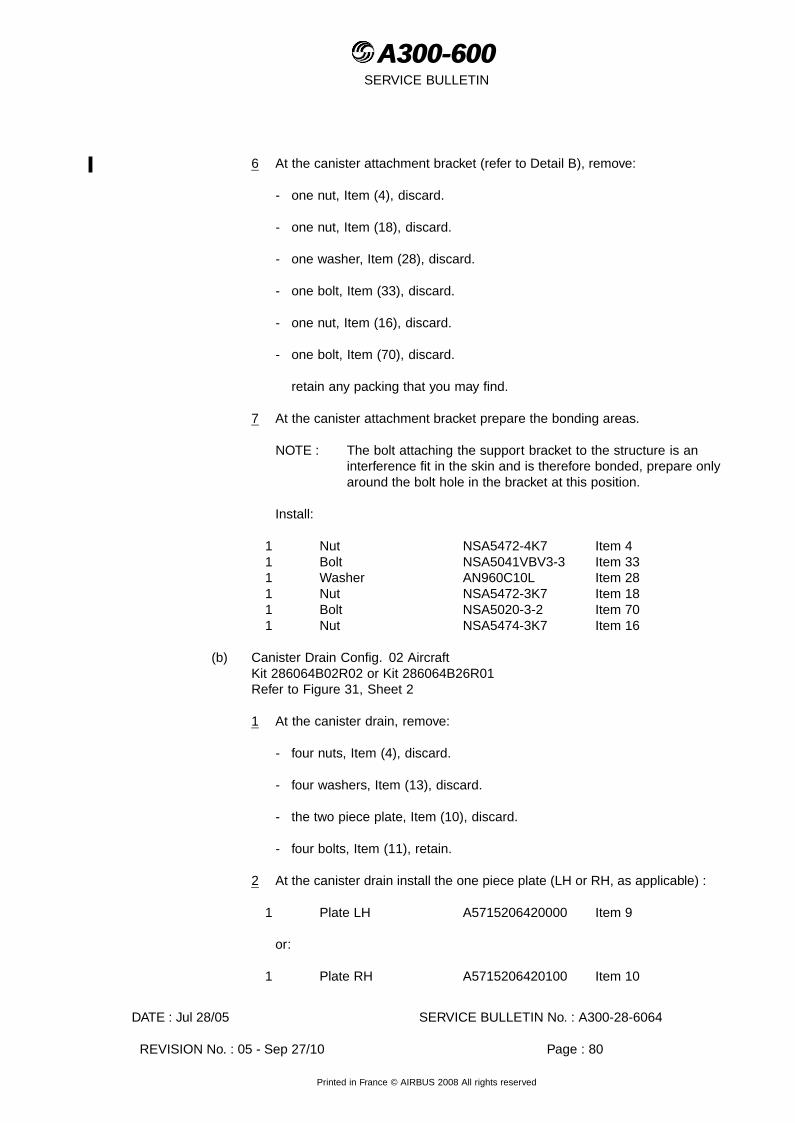
A300-600A300-600SERVICE BULLETIN
6 At the canister attachment bracket (refer to Detail B), remove:
- one nut, Item (4), discard.
- one nut, Item (18), discard.
- one washer, Item (28), discard.
- one bolt, Item (33), discard.
- one nut, Item (16), discard.
- one bolt, Item (70), discard.
retain any packing that you may find.
7 At the canister attachment bracket prepare the bonding areas.
NOTE : The bolt attaching the support bracket to the structure is aninterference fit in the skin and is therefore bonded, prepare onlyaround the bolt hole in the bracket at this position.
Install:
1 Nut NSA5472-4K7 Item 41 Bolt NSA5041VBV3-3 Item 331 Washer AN960C10L Item 281 Nut NSA5472-3K7 Item 181 Bolt NSA5020-3-2 Item 701 Nut NSA5474-3K7 Item 16
(b) Canister Drain Config. 02 AircraftKit 286064B02R02 or Kit 286064B26R01Refer to Figure 31, Sheet 2
1 At the canister drain, remove:
- four nuts, Item (4), discard.
- four washers, Item (13), discard.
- the two piece plate, Item (10), discard.
- four bolts, Item (11), retain.
2 At the canister drain install the one piece plate (LH or RH, as applicable) :
1 Plate LH A5715206420000 Item 9
or:
1 Plate RH A5715206420100 Item 10
DATE : Jul 28/05 SERVICE BULLETIN No. : A300-28-6064
REVISION No. : 05 - Sep 27/10 Page : 80
Printed in France © AIRBUS 2008 All rights reserved

A300-600A300-600SERVICE BULLETIN
with:
- three retained bolts, Item (11).
3 Nut NSA5472-4K7 Item 4
NOTE : If Service Bulletin A300-57-6026 has been embodied, increasethe bolt holes diameter in the new plate, Item 9 or 10, to between7.142-7.193mm (0.2812-0.2832in.) for the second oversizebolts, Item (11).
3 Prepare the bonding area
NOTE : For the bolt through the wing skin prepare the countersink only.
Install:
- one retained bolt, Item (11).
1* Washer NAS1252-416L Item 13
NOTE : * A second washer can be installed to allow correct installation ofbolt (11), if necessary.
1 Nut NSA5472-4K7 Item 4
4 Apply Sealant (Mat. No. 09-001) over the three nuts and a fillet of sealantaround the new plate to seal.
(12) Rib Bay 11-12 (RH Wing Only)Kit 286064B07R01 All Aircraft
(a) CadensiconRefer to Figure 35, Sheet 1
1 At the mounting plate attachment to the front spar (refer to Detail A and B)remove:
- one nut, Item (20), discard.
- one bolt (Post. Mod. 04741), Item (55), discard.
or:
- one bolt (Pre. Mod. 04741), Item (58), discard.
2 At the cadensicon mounting plate, remove:
- one nut, Item (16), discard.
- one bolt, Item (56), discard.
3 At the cadensicon pipe prepare the bonding area and install:
DATE : Jul 28/05 SERVICE BULLETIN No. : A300-28-6064
REVISION No. : 05 - Sep 27/10 Page : 81
Printed in France © AIRBUS 2008 All rights reserved
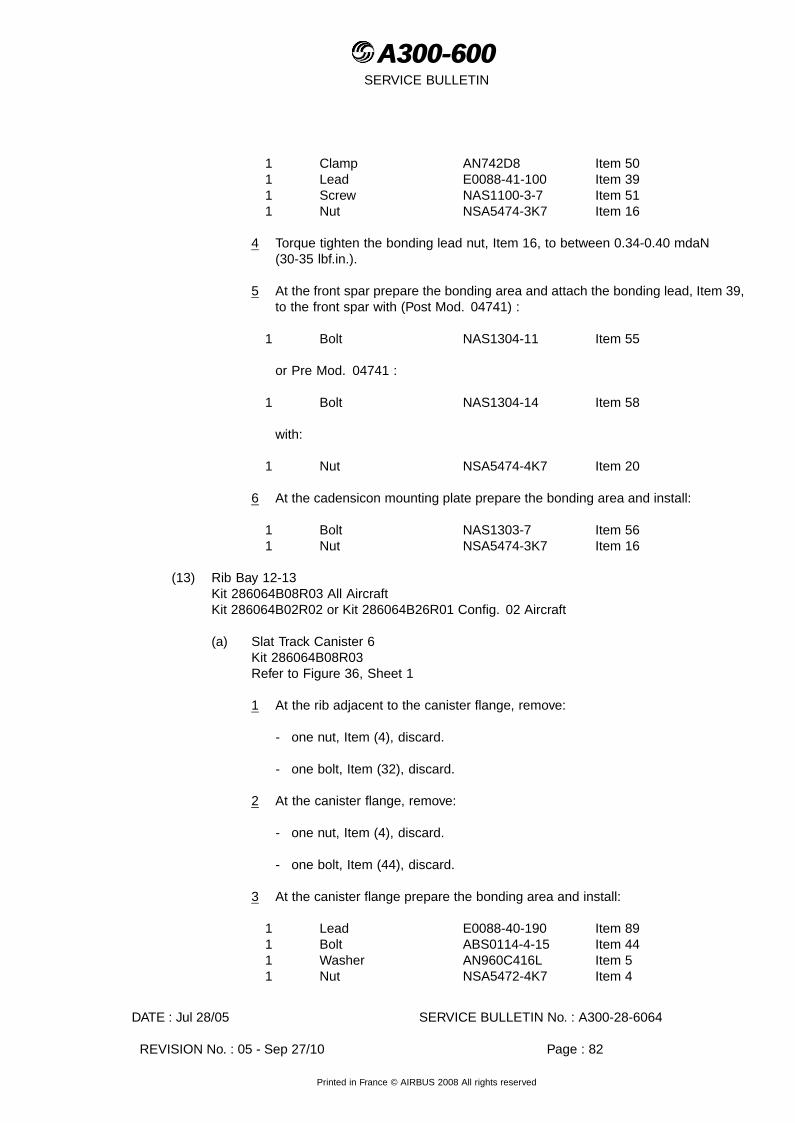
A300-600A300-600SERVICE BULLETIN
1 Clamp AN742D8 Item 501 Lead E0088-41-100 Item 391 Screw NAS1100-3-7 Item 511 Nut NSA5474-3K7 Item 16
4 Torque tighten the bonding lead nut, Item 16, to between 0.34-0.40 mdaN(30-35 lbf.in.).
5 At the front spar prepare the bonding area and attach the bonding lead, Item 39,to the front spar with (Post Mod. 04741) :
1 Bolt NAS1304-11 Item 55
or Pre Mod. 04741 :
1 Bolt NAS1304-14 Item 58
with:
1 Nut NSA5474-4K7 Item 20
6 At the cadensicon mounting plate prepare the bonding area and install:
1 Bolt NAS1303-7 Item 561 Nut NSA5474-3K7 Item 16
(13) Rib Bay 12-13Kit 286064B08R03 All AircraftKit 286064B02R02 or Kit 286064B26R01 Config. 02 Aircraft
(a) Slat Track Canister 6Kit 286064B08R03Refer to Figure 36, Sheet 1
1 At the rib adjacent to the canister flange, remove:
- one nut, Item (4), discard.
- one bolt, Item (32), discard.
2 At the canister flange, remove:
- one nut, Item (4), discard.
- one bolt, Item (44), discard.
3 At the canister flange prepare the bonding area and install:
1 Lead E0088-40-190 Item 891 Bolt ABS0114-4-15 Item 441 Washer AN960C416L Item 51 Nut NSA5472-4K7 Item 4
DATE : Jul 28/05 SERVICE BULLETIN No. : A300-28-6064
REVISION No. : 05 - Sep 27/10 Page : 82
Printed in France © AIRBUS 2008 All rights reserved

A300-600A300-600SERVICE BULLETIN
NOTE : The washer, Item 5, is only necessary under the nut, Item 4, if thebolt, Item 44, is installed from the front spar side and the nut isinstalled inside the fuel tank. This will give easier access at someflanges to torque tighten the nut.
4 At the rib adjacent to the canister flange prepare the bonding area and attachthe bonding lead, Item 89, with:
1 Bolt NSA5041VBV4-9 Item 321 Nut NSA5472-4K7 Item 4
5 Torque tighten the bonding lead nut, Item 4, to between 0.68-0.79 mdaN(60-70 lbf.in.).
6 At the canister attachment bracket, drill and remove one rivet.
7 Drill out the rivet hole to a finished size of 4.9 mm (0.1929 in.).
8 Deburr the hole.
9 At the canister attachment bracket, remove:
- one nut, Item (4), discard.
- one nut, Item (16), discard.
- one washer, Item (28), discard.
- one bolt, Item (41), discard.
retain any packing that you may find.
10 At the canister attachment bracket prepare the bonding areas.
NOTE : The bolt attaching the support bracket to the structure is aninterference fit in the skin and is therefore bonded, prepare onlyaround the bolt hole in the bracket at this position.
Install:
1 Nut NSA5472-4K7 Item 41 Bolt NSA5041VBV3-2 Item 411 Washer AN960C10L Item 282 Nut NSA5474-3K7 Item 161 Bolt NAS1303-1 Item 42
(b) Canister Drain Config. 02 AircraftKit 286064B02R02 or Kit 286064B26R01Refer to Figure 31, Sheet 2
1 At the canister drain, remove:
- four nuts, Item (4), discard.
DATE : Jul 28/05 SERVICE BULLETIN No. : A300-28-6064
REVISION No. : 05 - Sep 27/10 Page : 83
Printed in France © AIRBUS 2008 All rights reserved

A300-600A300-600SERVICE BULLETIN
- four washers, Item (13), discard.
- the two piece plate, Item (10), discard.
- four bolts, Item (11), retain.
2 At the canister drain install the one piece plate (LH or RH, as applicable) :
1 Plate LH A5715206420000 Item 9
or:
1 Plate RH A5715206420100 Item 10
with:
- three retained bolts, Item (11).
3 Nut NSA5472-4K7 Item 4
NOTE : If Service Bulletin A300-57-6026 has been embodied, increasethe bolt holes diameter in the new plate, Item 9 or 10, to between7.142-7.193mm (0.2812-0.2832in.) for the second oversizebolts, Item (11).
3 Prepare the bonding area.
NOTE : For the bolt through the wing skin prepare the countersink only.
Install:
- one retained bolt, Item (11).
1* Washer NAS1252-416L Item 13
NOTE : * A second washer can be installed to allow correct installation ofbolt (11), if necessary.
1 Nut NSA5472-4K7 Item 4
4 Apply Sealant (Mat. No. 09-001) over the three nuts and a fillet of sealantaround the new plate to seal.
(14) Rib Bay 13-14Kit 286064B09R04 All Aircraft
(a) MLIKit 286064B09R04Refer to Figure 25, Sheet 1, Detail B
1 At the base of the MLI, remove:
- one nut, Item (25), discard.
DATE : Jul 28/05 SERVICE BULLETIN No. : A300-28-6064
REVISION No. : 05 - Sep 27/10 Page : 84
Printed in France © AIRBUS 2008 All rights reserved
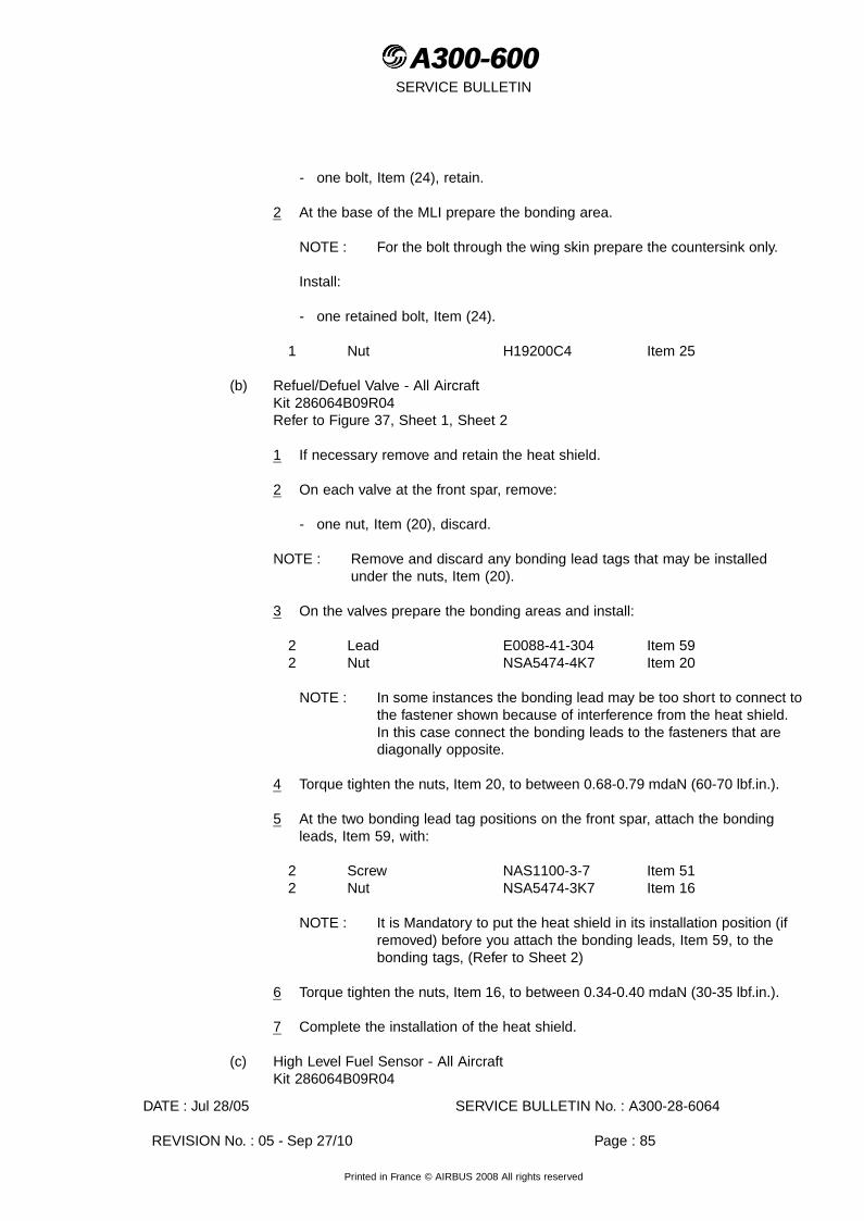
A300-600A300-600SERVICE BULLETIN
- one bolt, Item (24), retain.
2 At the base of the MLI prepare the bonding area.
NOTE : For the bolt through the wing skin prepare the countersink only.
Install:
- one retained bolt, Item (24).
1 Nut H19200C4 Item 25
(b) Refuel/Defuel Valve - All AircraftKit 286064B09R04Refer to Figure 37, Sheet 1, Sheet 2
1 If necessary remove and retain the heat shield.
2 On each valve at the front spar, remove:
- one nut, Item (20), discard.
NOTE : Remove and discard any bonding lead tags that may be installedunder the nuts, Item (20).
3 On the valves prepare the bonding areas and install:
2 Lead E0088-41-304 Item 592 Nut NSA5474-4K7 Item 20
NOTE : In some instances the bonding lead may be too short to connect tothe fastener shown because of interference from the heat shield.In this case connect the bonding leads to the fasteners that arediagonally opposite.
4 Torque tighten the nuts, Item 20, to between 0.68-0.79 mdaN (60-70 lbf.in.).
5 At the two bonding lead tag positions on the front spar, attach the bondingleads, Item 59, with:
2 Screw NAS1100-3-7 Item 512 Nut NSA5474-3K7 Item 16
NOTE : It is Mandatory to put the heat shield in its installation position (ifremoved) before you attach the bonding leads, Item 59, to thebonding tags, (Refer to Sheet 2)
6 Torque tighten the nuts, Item 16, to between 0.34-0.40 mdaN (30-35 lbf.in.).
7 Complete the installation of the heat shield.
(c) High Level Fuel Sensor - All AircraftKit 286064B09R04
DATE : Jul 28/05 SERVICE BULLETIN No. : A300-28-6064
REVISION No. : 05 - Sep 27/10 Page : 85
Printed in France © AIRBUS 2008 All rights reserved

A300-600A300-600SERVICE BULLETIN
Refer to Figure 30, Sheet 1, Detail B
1 At the sensor bracket, remove:
- one nut, Item (16), discard.
- one bolt, Item (70), discard.
2 At the support bracket, remove:
- one nut, Item (16), discard.
- one bolt, Item (17), discard.
or
- one bolt, Item (90), discard.
3 At the sensor bracket prepare the bonding area and install:
1 Bolt NSA5020-3-2 Item 701 Nut NSA5474-3K7 Item 16
4 At the support bracket prepare the bonding area and install:
1 Nut NSA5474-3K7 Item 161 Bolt NSA5020-3-3 Item 17
or
1 Bolt NSA5020-3-5 Item 90
NOTE : If bolt, Item 17, is too short the bolt, item 90, may be used asan alternative.
(d) Overwing Refuel PanelNo KitRefer to Figure 39, Sheet 1 and AMM 28-25-21, Page block 401
1 Put protective material or masking tape on the wing skin, around therefuel/defuel panels.
2 At the refuel panels loosen the bolts and lift the panel.
3 Put the panel on the protective material.
4 At the contact surfaces of the panel and the wing skin opening (Refer to theFigure) use abrasive paper grade 1 or Emery cloth, grade 320, to removeany protective coating. Clean the prepared surfaces with Cleaning agent(Mat. No. 11-026).
5 Apply Alodine (Mat. No. 13-002) to the contact surfaces of the panel andthe wing skin.
DATE : Jul 28/05 SERVICE BULLETIN No. : A300-28-6064
REVISION No. : 05 - Sep 27/10 Page : 86
Printed in France © AIRBUS 2008 All rights reserved

A300-600A300-600SERVICE BULLETIN
6 Apply sealant (Mat. No. 09-018) to the contact surface of the wing skin.
7 Align the panel offset bolt and put the panel into the wing skin opening. Makesure that the panel attachment chain is clear of the bolt holes.
8 Tighten the bolts.
9 Remove any unwanted sealant.
10 Remove the protective material that you put around the opening.
11 If necessary, apply paint to the heads of the bolts and the panel and/or wing skin(Refer to SRM 51-75-10).
(15) Rib Bay 14-15Kit 286064B10R01 All AircraftKit 286064B02R02 or Kit 286064B26R01 Config. 02 AircraftKit 286064B25R01 Config. 07 Aircraft
(a) Screwjack Canister 4Kit 286064B10R01Refer to Figure 40, Sheet 1
1 At the rib adjacent to the canister flange, remove:
- one nut, Item (4), discard.
- one bolt, Item (54), discard.
2 At the canister flange, remove:
- one nut, Item (4), discard.
- one bolt, Item (57), discard.
3 At the canister flange prepare the bonding area and install:
1 Lead E0088-40-100 Item 11 Bolt ABS0114-4-14 Item 571 Washer AN960C416L Item 51 Nut NSA5472-4K7 Item 4
NOTE : The washer, Item 5, is only necessary under the nut, Item 4, if thebolt, Item 57, is installed from the front spar side and the nut isinstalled inside the fuel tank. This will give easier access at someflanges to torque tighten the nut.
4 At the rib adjacent to the canister flange prepare the bonding area and attachthe bonding lead, Item 1, with:
1 Bolt NSA5041VBV4-7 Item 541 Nut NSA5472-4K7 Item 4
DATE : Jul 28/05 SERVICE BULLETIN No. : A300-28-6064
REVISION No. : 05 - Sep 27/10 Page : 87
Printed in France © AIRBUS 2008 All rights reserved
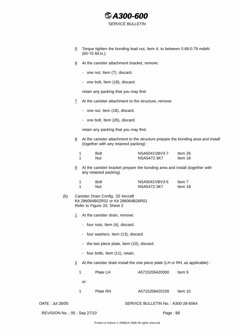
A300-600A300-600SERVICE BULLETIN
5 Torque tighten the bonding lead nut, Item 4, to between 0.68-0.79 mdaN(60-70 lbf.in.).
6 At the canister attachment bracket, remove:
- one nut, Item (7), discard.
- one bolt, Item (18), discard.
retain any packing that you may find.
7 At the canister attachment to the structure, remove:
- one nut, Item (18), discard.
- one bolt, Item (26), discard.
retain any packing that you may find.
8 At the canister attachment to the structure prepare the bonding area and install(together with any retained packing) :
1 Bolt NSA5041VBV3-7 Item 261 Nut NSA5472-3K7 Item 18
9 At the canister bracket prepare the bonding area and install (together withany retained packing)
1 Bolt NSA5041VBV3-5 Item 71 Nut NSA5472-3K7 Item 18
(b) Canister Drain Config. 02 AircraftKit 286064B02R02 or Kit 286064B26R01Refer to Figure 33, Sheet 2
1 At the canister drain, remove:
- four nuts, Item (4), discard.
- four washers, Item (13), discard.
- the two piece plate, Item (10), discard.
- four bolts, Item (11), retain.
2 At the canister drain install the one piece plate (LH or RH, as applicable) :
1 Plate LH A5715206420000 Item 9
or:
1 Plate RH A5715206420100 Item 10
DATE : Jul 28/05 SERVICE BULLETIN No. : A300-28-6064
REVISION No. : 05 - Sep 27/10 Page : 88
Printed in France © AIRBUS 2008 All rights reserved

A300-600A300-600SERVICE BULLETIN
with:
- three retained bolts, Item (11).
3 Nut NSA5472-4K7 Item 4
NOTE : If Service Bulletin A300-57-6026 has been embodied, increasethe bolt holes diameter in the new plate, Item 9 or 10, to between7.142-7.193mm (0.2812-0.2832in.) for the second oversizebolts, Item (11).
3 Prepare the bonding area.
NOTE : For the bolt through the wing skin prepare the countersink only.
Install:
- one retained bolt, Item (11).
1* Washer NAS1252-416L Item 13
NOTE : * A second washer can be installed to allow correct installation ofbolt (11), if necessary.
1 Nut NSA5472-4K7 Item 4
4 Apply Sealant (Mat. No. 09-001) over the three nuts and a fillet of sealantaround the new plate to seal.
(c) Water Drain Valve - All AircraftKit 286064B10R01Refer to Figure 23, Sheet 1, Sheet 2
1 At the water drain pipe (refer to Sheet 2, Detail A) disconnect the bonding lead,Item (84) from the bonding lug, remove:
- one nut, Item (80), discard.
- one bolt, Item (81), discard.
CAUTION : DO NOT REMOVE AND DISCARD ANY OTHER BONDING LEADSFROM RIB 14.
2 At the bonding leads attachment to rib 14 (adjacent to the compensator), remove:
- one nut, Item (16), discard.
- one bolt, Item (22), retain.
- one bonding lead, Item (84), discard.
NOTE : If necessary, temporarily remove any other bonding leads to getaccess to the bonding lead, Item (84) at rib 14.
DATE : Jul 28/05 SERVICE BULLETIN No. : A300-28-6064
REVISION No. : 05 - Sep 27/10 Page : 89
Printed in France © AIRBUS 2008 All rights reserved

A300-600A300-600SERVICE BULLETIN
3 At the bonding leads attachment to rib 14, install (together with any otherbonding leads that you temporarily removed for access) :
- one retained bolt, Item (22).
1 Nut NSA5474-3K7 Item 16
4 At the bonding leads attachment to rib 14, apply protective coating over thefastener and the bonding leads terminals (refer to AMM 20-28-11, Page block 1).
5 At the water drain pipe, apply Sealant (Mat. No. 09-001) over the bonding lug.
6 At the base of the water drain valve (refer to Sheet 1 Detail A), remove:
- one nut, Item (20), discard.
- one bolt, Item (19), retain.
7 At water drain valve-pipe prepare the bonding area and install:
1 Clamp AN742D6 Item 151 Lead E0088-41-160 Item 141 Bolt NSA5020-3-3 Item 171 Nut NSA5474-3K7 Item 16
8 At the base of the water drain valve prepare the bonding area.
NOTE : For the bolt through the wing skin prepare the countersink only.
Install:
- one retained bolt, Item (19).
- the other end of the lead, Item 14.
1 Nut NSA5474-4K7 Item 20
9 Torque tighten the bonding lead nut, Item 16, to between 0.34-0.40 mdaN(30-35 lbf.in.).
(d) Low Fuel Pressure SwitchesKit 286064B10R01Refer to Figure 27, Sheet 2, Detail D
1 At each pressure switch attachment to the rear spar, remove:
- one nut, Item (16), discard.
- one bolt, Item (69), discard.
2 At the pressure switches pipes prepare the bonding area and install:
2 Clamp NSA5519-2B Item 35
DATE : Jul 28/05 SERVICE BULLETIN No. : A300-28-6064
REVISION No. : 05 - Sep 27/10 Page : 90
Printed in France © AIRBUS 2008 All rights reserved

A300-600A300-600SERVICE BULLETIN
2 Lead E0088-10-100 Item 382 Nut NSA5474-3K7 Item 162 Bolt NAS1303-2 Item 37
3 At the pressure switches attachment to the rear spar prepare the bonding areasand attach the bonding leads, Item 38, with:
2 Bolt NSA5041VBV3-6 Item 692 Nut NSA5474-3K7 Item 16
4 Torque tighten the bonding lead nuts, Item 16, to between 0.34-0.40 mdaN(30-35 lbf.in.).
(e) Fuel Booster PumpsKit 286064B10R01Refer to Figure 41, Sheet 1
1 At each canister flange, remove from the positions shown in the figure:
- two bolts, Item (45), discard.
CAUTION : BOLTS THAT GO THROUGH THE FAIRING ARE NOT TO BE USEDAS BONDING POINTS.
2 At the canister flanges prepare the bonding areas and for the bolts through thewing skin prepare the countersink only.
Install:
4 Bolt NSA5022-4-21 Item 45
3 At each of the fuel pump canisters, adjacent to the existing bonding lead,(refer to Detail C) remove:
- one nut, Item (20), discard.
- one bolt, Item (43), retain.
4 On the two pressure switches pipes prepare the bonding areas and install:
2 Clamp NSA5519-2B Item 352 Lead E0088-41-100 Item 392 Bolt NAS1303-2 Item 372 Nut NSA5474-3K7 Item 16
5 Torque tighten the bonding lead nuts, Item 16, to between 0.34-0.40 mdaN(30-35 lbf.in.).
6 At the two fuel pump canisters, adjacent to the existing bonding lead, (refer toDetail C) prepare the bonding areas and attach the bonding leads, Item 39, with:
- 2 retained bolts, Item (43).
DATE : Jul 28/05 SERVICE BULLETIN No. : A300-28-6064
REVISION No. : 05 - Sep 27/10 Page : 91
Printed in France © AIRBUS 2008 All rights reserved

A300-600A300-600SERVICE BULLETIN
2 Nut NSA5474-4K7 Item 20
7 Torque tighten the nuts, Item 20, to between 0.68-0.79 mdaN (60-70 lbf.in.).
(f) Fuel Jettison System - Blanking PlatesKit 286064B25R01 Config. 07 AircraftRefer to Figure 38, Sheet 1, Detail A and B
NOTE : Access to rib bays 13-14 and 15-16 is also necessary.
1 At the blanking plate at rib 14 (refer to Detail A), remove:
- one nut, Item (20), discard.
- one bolt, Item (62), discard.
2 At the blanking plate prepare the bonding area and install:
1 Bolt NSA5041VBV4-6 Item 621 Nut NSA5474-4K7 Item 20
3 At the blanking plate at rib 15 (refer to Detail B), remove:
- one nut, Item (16), discard.
- one bolt, Item (69), discard.
4 At the blanking plate prepare the bonding area and install:
1 Bolt NSA5041VBV3-6 Item 691 Nut NSA5474-3K7 Item 16
(16) Rib Bay 15-16Kit 286064B11R05 All AircraftKit 286064B02R02 or Kit 286064B26R01 Config. 02 Aircraft
(a) Slat Track Canister 7Kit 286064B11R05Refer to Figure 42, Sheet 1
1 At the rib adjacent to the canister flange, remove:
- one nut, Item (4), discard.
- one bolt, Item (29), discard.
2 At the canister flange, remove:
- one nut, Item (4), discard.
- one bolt, Item (85), discard
3 At the canister flange prepare the bonding area and install:
DATE : Jul 28/05 SERVICE BULLETIN No. : A300-28-6064
REVISION No. : 05 - Sep 27/10 Page : 92
Printed in France © AIRBUS 2008 All rights reserved

A300-600A300-600SERVICE BULLETIN
1 Lead E0088-40-100 Item 11 Bolt ABS0114-4-13 Item 851 Washer AN960C416L Item 51 Nut NSA5472-4K7 Item 4
NOTE : The washer, Item 5, is only necessary under the nut, Item 4, if thebolt, Item 85, is installed from the front spar side and the nut isinstalled inside the fuel tank. This will give easier access at someflanges to torque tighten the nut.
4 At the rib adjacent to the canister prepare the bonding area and attach thebonding lead, Item 1, with:
1 Bolt NSA5041VBV4-8 Item 291 Nut NSA5472-4K7 Item 4
5 Torque tighten the bonding lead nut, Item 4, to between 0.68-0.79 mdaN(60-70 lbf.in.).
6 At the canister attachment bracket, drill and remove one rivet.
7 Drill out the rivet hole to a finished size of 4.9 mm (0.1929 in.).
8 Deburr the hole.
9 At the canister attachment bracket position (refer to Detail C), remove:
- one nut, Item (4), discard.
- one nut, Item (18), discard.
- one washer, Item (28), discard.
- one bolt, Item (33), discard.
retain any packing that you may find.
10 At the canister attachment bracket prepare the bonding areas.
NOTE : The bolt attaching the support bracket to the structure is aninterference fit in the skin and therefore bonded, prepare onlyaround the bolt hole in the bracket at this position.
Install:
1 Nut NSA5472-4K7 Item 41 Bolt NSA5041VBV3-3 Item 331 Washer AN960C10L Item 282 Nut NSA5472-3K7 Item 181 Bolt NSA5020-3-2 Item 70
(b) Canister Drain Config. 02 AircraftKit 286064B02R02 or Kit 286064B26R01
DATE : Jul 28/05 SERVICE BULLETIN No. : A300-28-6064
REVISION No. : 05 - Sep 27/10 Page : 93
Printed in France © AIRBUS 2008 All rights reserved

A300-600A300-600SERVICE BULLETIN
Refer to Figure 31, Sheet 2
1 At the canister drain, remove:
- four nuts, Item (4), discard.
- four washers, Item (13), discard.
- the two piece plate, Item (10), discard.
- four bolts, Item (11), retain.
2 At the canister drain install the one piece plate (LH or RH, as applicable) :
1 Plate LH A5715206420000 Item 9
or:
1 Plate RH A5715206420100 Item 10
with:
- three retained bolts, Item (11).
3 Nut NSA5472-4K7 Item 4
NOTE : If Service Bulletin A300-57-6026 has been embodied, increasethe bolt holes diameter in the new plate, Item 9 or 10, to between7.142-7.193mm (0.2812-0.2832in.) for the second oversizebolts, Item (11).
3 Prepare the bonding area.
NOTE : For the bolt through the wing skin prepare the countersink only.
Install:
- one retained bolt, Item (11).
1* Washer NAS1252-416L Item 13
NOTE : * A second washer can be installed to allow correct installation ofbolt (11), if necessary.
1 Nut NSA5472-4K7 Item 4
4 Apply sealant (Mat. No. 09-001) over the three nuts and a fillet of sealantaround the new plate to seal.
(c) Diffuser - All AircraftKit 286064B11R05Refer to Figure 29, Sheet 3
DATE : Jul 28/05 SERVICE BULLETIN No. : A300-28-6064
REVISION No. : 05 - Sep 27/10 Page : 94
Printed in France © AIRBUS 2008 All rights reserved

A300-600A300-600SERVICE BULLETIN
1 At the diffuser attachment brackets remove:
- two nuts, Item (20), discard.
- two washers, Item (52) (if installed), discard.
- two bolts, Item (46), discard.
- one washer if fitted, Item (53), discard.
2 At the diffuser attachment to the structure, remove:
- two nuts, Item (49), discard.
or
- two nuts, Item (4), discard.
3 At the diffuser prepare the bonding areas and install:
2 Bolt NAS1304-3 Item 462 Washer A2824028520000 Item 521 Washer AN960PD416 Item 532 Nut NSA5474-4K7 Item 20
4 At the diffuser attachment to the structure prepare the bonding areas and install:
NOTE : The bolts attaching the support brackets to the structure are aninterference fit in the skin and are therefore bonded, prepare onlyaround the bolt hole in the bracket at this position.
2 Nut NSA5472-5K7 Item 49
or
2 Nut NSA5472-4K7 Item 4
(d) Water Drain Valve - All AircraftKit 286064B11R05Refer to Figure 23, Sheet 1
1 At the base of the water drain valve, (refer to Detail A) remove:
- one nut, Item (20), discard.
- one bolt, Item (19), retain.
2 At the water drain pipe prepare the bonding area and install:
1 Clamp AN742D6 Item 151 Lead E0088-41-160 Item 141 Bolt NSA5020-3-3 Item 171 Nut NSA5474-3K7 Item 16
DATE : Jul 28/05 SERVICE BULLETIN No. : A300-28-6064
REVISION No. : 05 - Sep 27/10 Page : 95
Printed in France © AIRBUS 2008 All rights reserved

A300-600A300-600SERVICE BULLETIN
3 Torque tighten the bonding lead nut, Item 16, to between 0.34-0.40 mdaN(30-35 lbf.in.).
4 At the base of the water drain valve prepare the bonding area.
NOTE : For the bolt through the wing skin prepare the countersink only.
Install:
- one retained bolt, Item (19).
- the other end of bonding lead, Item 14.
1 Nut NSA5474-4K7 Item 20
5 Torque tighten the nut, Item 20, to between 0.68-0.79 mdaN (60-70 lbf.in.)
(17) Rib Bay 16-17Kit 286064B12R01 All Aircraft
(a) Fuel Level SensorRefer to Figure 30, Sheet 2, Detail D
1 At the sensor bracket, remove:
- one nut, Item (16), discard.
- one bolt, Item (70), discard.
2 At the support bracket, remove:
- one nut, Item (16), discard.
- one bolt, Item (71), discard.
3 at the sensor bracket prepare the bonding area and install:
1 Bolt NSA5020-3-2 Item 701 Nut NSA5474-3K7 Item 16
4 At the support bracket prepare the bonding area and install:
1 Bolt NSA5020-3-4 Item 711 Nut NSA5474-3K7 Item 16
(18) Rib Bay 17-18Kit 286064B25R01Refer to Figure 38, Sheet 1
(a) Fuel Jettison System Blanking Plates
1 At the blanking plates, remove:
DATE : Jul 28/05 SERVICE BULLETIN No. : A300-28-6064
REVISION No. : 05 - Sep 27/10 Page : 96
Printed in France © AIRBUS 2008 All rights reserved

A300-600A300-600SERVICE BULLETIN
- one bolt, Item (66), discard.
- one bolt, Item (68), discard.
- one nut, Item (16), discard.
- one nut, Item (20), discard.
2 At the blanking plates prepare the bonding areas and install:
1 Bolt NAS1153-12 Item 661 Nut NSA5474-3K7 Item 161 Bolt NSA5041VBV4-14 Item 681 Nut NSA5474-4K7 Item 20
(19) Rib Bay 18-19Kit 286064B13R03 All AircraftKit 286064B02R02 or Kit 286064B26R01 for Config. 01 and Config. 02 aircraft.
(a) Slat Track Canister 8Kit 286064B13R03Refer to Figure 43, Sheet 1
1 At the rib adjacent to the canister flange, remove:
- one nut, Item (4), discard.
- one bolt, Item (29), discard.
2 At the canister flange, remove:
- one nut, Item (4), discard.
- one bolt, Item (61), discard.
3 At the canister flange prepare the bonding area and install:
1 Lead E0088-40-100 Item 11 Bolt ABS0114-4-12 Item 611 Washer AN960C416L Item 51 Nut NSA5472-4K7 Item 4
NOTE : The washer, Item 5, is only necessary under the nut, Item 4, if thebolt, Item 61, is installed from the front spar side and the nut isinstalled inside the fuel tank. This will give easier access at someflanges to torque tighten the nut.
4 At the rib adjacent to the canister flange prepare the bonding area and attachthe bonding lead, Item 1, with:
1 Bolt NSA5041VBV4-8 Item 291 Nut NSA5472-4K7 Item 4
DATE : Jul 28/05 SERVICE BULLETIN No. : A300-28-6064
REVISION No. : 05 - Sep 27/10 Page : 97
Printed in France © AIRBUS 2008 All rights reserved

A300-600A300-600SERVICE BULLETIN
5 Torque tighten the bonding lead nut, Item 4, to between 0.68-0.79 mdaN(60-70 lbf.in.).
6 At the canister attachment bracket, drill and remove one rivet.
7 Drill out the rivet hole to a finished size of 4.9 mm (0.1929 in.).
8 Deburr the hole.
9 At the canister attachment brackets (refer to Detail C) remove:
- one nut, Item (4), discard.
- one bolt, Item (33), discard.
- one washer, Item (28), discard.
- one nut, Item (18), discard.
- one nut, Item (16), discard.
retain any packing that you may find.
10 At the canister attachment bracket prepare the bonding areas
NOTE : The bolt attaching the support bracket to the structure is aninterference fit in the skin and is therefore bonded, prepare onlyaround the bolt hole in the bracket at this position.
Install (together with any retained packing) :
1 Nut NSA5472-4K7 Item 41 Bolt NAS1303-1 Item 421 Nut NSA5474-3K7 Item 161 Bolt NSA5041VBV3-3 Item 331 Washer AN960C10L Item 281 Nut NSA5472-3K7 Item 18
(b) Canister Drain Config. 01 and Config. 02 aircraft.Kit 286064B02R02 or Kit 286064B26R01Refer to Figure 31, Sheet 2
1 At the canister drain, remove:
- four nuts, Item (4), discard.
- four washers, Item (13), discard.
- the two piece plate, Item (10), discard.
- four bolts, Item (11), retain.
DATE : Jul 28/05 SERVICE BULLETIN No. : A300-28-6064
REVISION No. : 05 - Sep 27/10 Page : 98
Printed in France © AIRBUS 2008 All rights reserved

A300-600A300-600SERVICE BULLETIN
2 At the canister drain install the one piece plate (Item 9 LH or Item 10 RH,as applicable) :
1 Plate LH A5715206420000 Item 9
or:
1 Plate RH A5715206420100 Item 10
with:
- three retained bolts, Item (11).
3 Nut NSA5472-4K7 Item 4
NOTE : If Service Bulletin A300-57-6026 has been embodied, increasethe bolt holes diameter in the new plate, Item 9 or 10, to between7.142-7.193mm (0.2812-0.2832in.) for the second oversizebolts, Item (11).
3 Prepare the bonding area.
NOTE : For the bolt through the wing skin prepare the countersink only.
Install:
- one retained bolt, Item (11).
1* Washer NAS1252-416L Item 13
NOTE : * A second washer can be installed to allow correct installation ofbolt (11), if necessary.
1 Nut NSA5472-4K7 Item 4
4 Apply sealant (Mat. No. 09-001) over the three nuts and a fillet of sealantaround the new plate to seal.
(20) Rib Bay 20-21Kit 286064B14R02 All AircraftKit 286064B02R02 or Kit 286064B26R01 Config. 02 Aircraft
(a) Screwjack Canister 5Kit 286064B14R02Refer to Figure 44, Sheet 1
1 At the rib adjacent to the canister flange, remove:
- one nut, Item (4), discard.
- one bolt, Item (54), discard.
2 At the canister flange, remove:
DATE : Jul 28/05 SERVICE BULLETIN No. : A300-28-6064
REVISION No. : 05 - Sep 27/10 Page : 99
Printed in France © AIRBUS 2008 All rights reserved

A300-600A300-600SERVICE BULLETIN
- one nut, Item (4), discard.
- one bolt, Item (63), discard.
3 At the canister flange prepare the bonding area and install:
1 Lead E0088-40-100 Item 11 Bolt ABS0114-4-10 Item 631 Washer AN960C416L Item 51 Nut NSA5472-4K7 Item 4
NOTE : The washer, Item 5, is only necessary under the nut, Item 4, if thebolt, Item 63, is installed from the front spar side and the nut isinstalled inside the fuel tank. This will give easier access at someflanges to torque tighten the nut.
4 At the rib adjacent to the canister flange prepare the bonding area and attachthe bonding lead, Item 1, with:
1 Bolt NSA5041VBV4-7 Item 541 Nut NSA5472-4K7 Item 4
5 At the canister attachment bracket, remove:
- one nut, Item (4), discard.
- one bolt, Item (12), discard.
6 At the bracket attachment to the structure, remove:
- one nut, Item (16), discard.
- one bolt, Item (69), discard.
7 At the canister attachment bracket prepare the bonding area and install:
1 Bolt NSA5041VBV4-5 Item 121 Nut NSA5472-4K7 Item 4
8 At the bracket attachment to the structure prepare the bonding area and install:
1 Bolt NSA5041VBV3-6 Item 691 Nut NSA5474-3K7 Item 16
(b) Canister Drain Config. 02 AircraftKit 286064B02R02 or Kit 286064B26R01Refer to Figure 33, Sheet 2
1 At the canister drain, remove:
- four nuts, Item (4), discard.
- four washers, Item (13), discard.
DATE : Jul 28/05 SERVICE BULLETIN No. : A300-28-6064
REVISION No. : 05 - Sep 27/10 Page : 100
Printed in France © AIRBUS 2008 All rights reserved

A300-600A300-600SERVICE BULLETIN
- the two piece plate, Item (10), discard.
- four bolts, Item (11), retain.
2 At the canister drain install the one piece plate (Item 9 LH or Item 10 RH,as applicable) :
1 Plate LH A5715206420000 Item 9
or:
1 Plate RH A5715206420100 Item 10
with:
- three retained bolts, Item (11).
3 Nut NSA5472-4K7 Item 4
NOTE : If Service Bulletin A300-57-6026 has been embodied, increase thebolt holes diameter in the new plate, Item 9 or 10, to between7.142-7.193mm (0.2812-0.2832in.) for the second oversize bolts,Item (11).
3 Prepare the bonding area.
NOTE : For the bolt through the wing skin prepare the countersink only.
Install:
- one retained bolt, Item (11).
1* Washer NAS1252-416L Item 13
NOTE : * A second washer can be installed to allow correct installation ofbolt (11), if necessary.
1 Nut NSA5472-4K7 Item 4
4 Apply sealant (Mat. No. 09-001) over the three nuts and a fillet of sealantaround the new plate to seal.
(c) MLI - All AircraftKit 286064B14R02Refer to Figure 25, Sheet 1, Detail B
1 At the base of the MLI, remove:
- one nut, Item (25), discard.
- one bolt, Item (24), retain.
2 At the base of the MLI prepare the bonding area.
DATE : Jul 28/05 SERVICE BULLETIN No. : A300-28-6064
REVISION No. : 05 - Sep 27/10 Page : 101
Printed in France © AIRBUS 2008 All rights reserved

A300-600A300-600SERVICE BULLETIN
NOTE : For the bolt through the wing skin prepare the countersink only.
Install:
- one retained bolt, Item (24).
1 Nut H19200C4 Item 25
(21) Rib Bay 21-22Kit 286064B15R04 All AircraftKit 286064B02R02 or Kit 286064B26R01 for Config. 01 and Config. 02 aircraft.
(a) Slat Track Canister 9Kit 286064B15R04Refer to Figure 45, Sheet 1
1 At the rib adjacent to the canister flange, remove:
- one nut, Item (64), discard.
- one bolt, Item (12), discard.
2 At the canister flange, remove:
- one nut, Item (64), discard.
- one bolt, Item (86), discard.
3 At the canister flange prepare the bonding area and install:
1 Lead E0088-40-100 Item 11 Bolt ABS0114-4-9 Item 861 Washer AN960C416L Item 51 Nut NSA5475-4K7 Item 64
NOTE : The washer, Item 5, is only necessary under the nut, Item 64, ifthe bolt, Item 86, is installed from the front spar side and the nut isinstalled inside the fuel tank. This will give easier access at someflanges to torque tighten the nut.
4 At the rib adjacent to the canister flange prepare the bonding area and attachthe bonding lead, Item 1, with:
1 Bolt NSA5041VBV4-5 Item 121 Nut NSA5475-4K7 Item 64
5 Torque tighten the bonding lead nut, Item 2, to between 0.68-0.79 mdaN(60-70 lbf.in.).
6 At the inboard canister attachment bracket position (refer to Detail C), remove:
- one nut, Item (4), discard.
DATE : Jul 28/05 SERVICE BULLETIN No. : A300-28-6064
REVISION No. : 05 - Sep 27/10 Page : 102
Printed in France © AIRBUS 2008 All rights reserved

A300-600A300-600SERVICE BULLETIN
- two nuts, Item (16), discard.
- one bolt, Item (41), discard.
- one bolt, Item (42), discard.
- one washer, Item (28), discard.
retain any packing that you may find.
7 At the canister attachment bracket prepare the bonding areas.
NOTE : The bolt attaching the support bracket to the structure is aninterference fit in the skin and is therefore bonded, prepare onlyaround the bolt hole in the bracket at this position.
Install (together with any retained packing) :
1 Nut NSA5472-4K7 Item 41 Bolt NAS1303-1 Item 422 Nut NSA5474-3K7 Item 161 Bolt NSA5041VBV3-2 Item 411 Washer AN960C10L Item 28
(b) Canister Drain Config. 01 and Config. 02 Aircraft.Kit 286064B02R02 or Kit 286064B26R01Refer to Figure 31, Sheet 2
1 At the canister drain, remove:
- four nuts, Item (4), discard.
- four washers, Item (13), discard.
- the two piece plate, Item (10), discard.
- four bolts, Item (11), retain.
2 At the canister drain install the plate (Item 9 LH or Item 10 RH, as applicable) :
1 Plate LH A5715206420000 Item 9
or:
1 Plate RH A5715206420100 Item 10
with:
- three retained bolts, Item (11).
3 Nut NSA5472-4K7 Item 4
DATE : Jul 28/05 SERVICE BULLETIN No. : A300-28-6064
REVISION No. : 05 - Sep 27/10 Page : 103
Printed in France © AIRBUS 2008 All rights reserved

A300-600A300-600SERVICE BULLETIN
NOTE : If Service Bulletin A300-57-6026 has been embodied, increase thebolt holes diameter in the new plate, Item 9 or 10, to between7.142-7.193mm (0.2812-0.2832in.) for the second oversize bolts,Item (11).
3 Prepare the bonding area.
NOTE : For the bolt through the wing skin prepare the countersink only.
Install:
- one retained bolt, Item (11).
1* Washer NAS1252-416L Item 13
NOTE : * A second washer can be installed to allow correct installation ofbolt (11), if necessary.
1 Nut NSA5472-4K7 Item 4
4 Apply sealant (Mat. No. 09-001) over the three nuts and a fillet of sealantaround the new plate to seal.
(22) Rib Bay 24-25Kit 286064B16R03 All AircraftKit 286064B02R02 or Kit 286064B26R01 for Config. 01 and Config. 02 Aircraft.
(a) Slat Track Canister 10Kit 286064B16R03Refer to Figure 46, Sheet 1
1 At the rib adjacent to the canister flange, remove:
- one nut, Item (64), discard.
- one bolt, Item (62), discard.
2 At the canister flange, remove:
- one nut, Item (64), discard.
- one bolt, Item (91), discard.
3 At the canister flange prepare the bonding area and install:
1 Lead E0088-40-100 Item 11 Bolt ABS0114-4-6 Item 911 Washer AN960C416L Item 51 Nut NSA5475-4K7 Item 64
NOTE : The washer, Item 5, is only necessary under the nut, Item 64, ifthe bolt, Item 91, is installed from the front spar side and the nut is
DATE : Jul 28/05 SERVICE BULLETIN No. : A300-28-6064
REVISION No. : 05 - Sep 27/10 Page : 104
Printed in France © AIRBUS 2008 All rights reserved

A300-600A300-600SERVICE BULLETIN
installed inside the fuel tank. This will give easier access at someflanges to torque tighten the nut.
4 At the rib adjacent to the canister flange prepare the bonding area and attachthe bonding lead, Item 1, with:
1 Bolt NSA5041VBV4-6 Item 621 Nut NSA5475-4K7 Item 64
5 Torque tighten the bonding lead nut, Item 2, to between 0.68-0.79 mdaN(60-70 lbf.in.).
6 At the canister attachment bracket (refer to Detail A), remove:
- two nuts, Item (16), discard.
- one washer, Item (28), discard.
- one bolt, Item (27), discard.
- one washer, Item (87), discard.
- one bolt, Item (7), discard.
retain any packing that you may find.
7 At the canister attachment bracket prepare the bonding areas and install(together with any retained packing) :
1 Bolt NSA5041VBV3-5 Item 71 Washer DHS1085-4 Item 871 Bolt NSA5041VBV3-4 Item 271 Washer AN960C10L Item 282 Nut NSA5474-3K7 Item 16
(b) Canister Drain, Config. 01 and Config. 02 Aircraft.Kit 286064B02R02 or Kit 286064B26R01Refer to Figure 31, Sheet 2
1 At the canister drain, remove:
- four nuts, Item (4), discard.
- four washers, Item (13), discard.
- the two piece plate, Item (10), discard.
- four bolts, Item (11), retain.
2 At the canister drain install the plate (Item 9 LH or Item 10 RH, as applicable) :
1 Plate LH A5715206420000 Item 9
DATE : Jul 28/05 SERVICE BULLETIN No. : A300-28-6064
REVISION No. : 05 - Sep 27/10 Page : 105
Printed in France © AIRBUS 2008 All rights reserved

A300-600A300-600SERVICE BULLETIN
or:
1 Plate RH A5715206420100 Item 10
with:
- three retained bolts, Item (11).
3 Nut NSA5472-4K7 Item 4
NOTE : If Service Bulletin A300-57-6026 has been embodied, increase the bolthole diameter in the new plate item 9 or 10, to between 7.142-7.193mm(0.2812-0.2832in) for the second oversize bolts, Item (11).
3 Prepare the bonding area.
NOTE : For the bolt through the skin prepare the countersink only.
Install:
- one retained bolt, Item (11).
1* Washer NAS1252-416L Item 13
NOTE : * A second washer can be installed to allow correct installation ofbolt (11), if necessary.
1 Nut NSA5472-4K7 Item 4
4 Apply sealant (Mat. No. 09-001) over the three nuts and a fillet of sealantaround the new plate to seal.
(23) Rib Bay 25-26Kit 286064B19R02 - All Aircraft
(a) Fuel Level SensorRefer to Figure 30, Sheet 1, Detail A
1 At the sensor bracket, remove:
- one bolt, Item (71), discard.
2 At the support bracket, remove:
- one nut, Item (16), discard.
- one bolt, Item (17), discard.
3 At the sensor bracket prepare the bonding area and install:
1 Bolt NSA5020-3-4 Item 71
4 At the support bracket prepare the bonding area and install:
DATE : Jul 28/05 SERVICE BULLETIN No. : A300-28-6064
REVISION No. : 05 - Sep 27/10 Page : 106
Printed in France © AIRBUS 2008 All rights reserved

A300-600A300-600SERVICE BULLETIN
1 Bolt NSA5020-3-3 Item 171 Nut NSA5474-3K7 Item 16
(24) Rib Bay 26-27Kit 286064B17R01 All AircraftKit 286064B27R01 or Kit 286064B28R01 Config. 02 Aircraft
(a) Screwjack Canister 6Kit 286064B17R01Refer to Figure 47, Sheet 1.
1 At the rib adjacent to the canister flange, remove:
- one nut, Item (4), discard.
- one bolt, Item (12), discard.
2 At the canister flange, remove:
- one nut, Item (4), discard.
- one bolt, Item (67), discard.
3 At the canister flange prepare the bonding area and install:
1 Lead E0088-40-100 Item 11 Bolt ABS0114-4-5 Item 671 Washer AN960C416L Item 51 Nut NSA5472-4K7 Item 4
NOTE : The washer, Item 5, is only necessary under the nut, Item 4, if thebolt, Item 67, is installed from the front spar side and the nut isinstalled inside the fuel tank. This will give easier access at someflanges to torque tighten the nut.
4 At the rib adjacent to the canister flange prepare the bonding area and attachthe bonding lead, Item 1, with:
1 Bolt NSA5041VBV4-5 Item 121 Nut NSA5472-4K7 Item 4
5 Torque tighten the bonding lead nut, Item 4, to between 0.68-0.79 mdaN(60-70 lbf.in.).
6 At the canister attachment bracket (refer to Detail A), remove
- one nut, Item (18), discard.
- one washer, Item (28), discard.
- one bolt, Item (72), discard.
retain any packing that you may find.
DATE : Jul 28/05 SERVICE BULLETIN No. : A300-28-6064
REVISION No. : 05 - Sep 27/10 Page : 107
Printed in France © AIRBUS 2008 All rights reserved

A300-600A300-600SERVICE BULLETIN
7 At the canister attachment bracket prepare the bonding area and install:
1 Bolt ABS0114-3-6 Item 721 Washer AN960C10L Item 281 Nut NSA5472-3K7 Item 18
(b) Canister Drain Config. 02 AircraftKit 286064B27R01 (LH) or Kit 286064B28R01 (RH)Refer to Figure 47, Sheet 2
1 At the canister drain remove:
- four nuts, Item (4), discard.
- the two piece plate, Item (10), discard.
- four bolts, Item (12), discard.
- packing, Item (6), retain.
2 At the drain spacer, Item (7) attachment to the wing skin, remove:
- one nut, Item (4), discard.
- one bolt, Item (5), retain.
3 At the drain spacer, Item (7) attachment to the wing skin prepare the bondingarea.
NOTE : For the bolt through the wing skin prepare the countersink only.
Install:
- 1 retained bolt, Item (5).
1 Nut NSA5472-4K7 Item 4
4 At the canister drain install the plate (Item 9 LH or Item 10 RH, as applicable) :
1 Plate LH A5715206420000 Item 9
or:
1 Plate RH A5715206420100 Item 10
with:
- retained packing, Item (6)
3 Bolt NSA5041VBV4-5 Item 123 Nut NSA5472-4K7 Item 4
5 Prepare the bonding area and install:
DATE : Jul 28/05 SERVICE BULLETIN No. : A300-28-6064
REVISION No. : 05 - Sep 27/10 Page : 108
Printed in France © AIRBUS 2008 All rights reserved
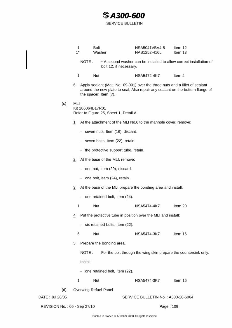
A300-600A300-600SERVICE BULLETIN
1 Bolt NSA5041VBV4-5 Item 121* Washer NAS1252-416L Item 13
NOTE : * A second washer can be installed to allow correct installation ofbolt 12, if necessary.
1 Nut NSA5472-4K7 Item 4
6 Apply sealant (Mat. No. 09-001) over the three nuts and a fillet of sealantaround the new plate to seal, Also repair any sealant on the bottom flange ofthe spacer, Item (7).
(c) MLIKit 286064B17R01Refer to Figure 25, Sheet 1, Detail A
1 At the attachment of the MLI No.6 to the manhole cover, remove:
- seven nuts, Item (16), discard.
- seven bolts, Item (22), retain.
- the protective support tube, retain.
2 At the base of the MLI, remove:
- one nut, Item (20), discard.
- one bolt, Item (24), retain.
3 At the base of the MLI prepare the bonding area and install:
- one retained bolt, Item (24).
1 Nut NSA5474-4K7 Item 20
4 Put the protective tube in position over the MLI and install:
- six retained bolts, Item (22).
6 Nut NSA5474-3K7 Item 16
5 Prepare the bonding area.
NOTE : For the bolt through the wing skin prepare the countersink only.
Install:
- one retained bolt, Item (22).
1 Nut NSA5474-3K7 Item 16
(d) Overwing Refuel Panel
DATE : Jul 28/05 SERVICE BULLETIN No. : A300-28-6064
REVISION No. : 05 - Sep 27/10 Page : 109
Printed in France © AIRBUS 2008 All rights reserved

A300-600A300-600SERVICE BULLETIN
No KitRefer to Figure 39 and AMM 28-25-21, Page block 401
1 Put protective material or masking tape on the wing skin, around therefuel/defuel panels.
2 At the refuel panels loosen the bolts and lift the panel.
3 Put the panel on the protective material.
4 At the contact surfaces of the panel and the wing skin opening (Refer to theFigure) use abrasive paper grade 1 or Emery cloth, grade 320, to removeany protective coating. Clean the prepared surfaces with Cleaning agent(Mat. No. 11-026).
5 Apply Alodine (Mat. No. 13-002) to the contact surfaces of the panel andthe wing skin.
6 Apply sealant (Mat. No. 09-018) to the contact surface of the wing skin.
7 Align the panel offset bolt and put the panel into the wing skin opening. Makesure that the panel attachment chain is clear of the bolt holes.
8 Tighten the bolts.
9 Remove any unwanted sealant.
10 Remove the protective material that you put around the opening.
11 If necessary, apply paint to the heads of the bolts and the panel and/or wing skin(Refer to SRM 51-75-10).
(25) Rib Bay 27-28Kit 286064B18R04 All AircraftKit 286064B02R02 or Kit 286064B26R01 for Config. 01 and Config. 02 Aircraft.
(a) Slat Track Canister 11Kit 286064B18R04Refer to Figure 48, Sheet 1
1 At the rib adjacent to the canister flange, remove:
- one nut, Item (64), discard.
- one bolt, Item (78), discard.
2 At the canister flange, remove:
- one nut, Item (64), discard.
- one bolt, Item (79), discard.
3 At the canister flange prepare the bonding area and install:
DATE : Jul 28/05 SERVICE BULLETIN No. : A300-28-6064
REVISION No. : 05 - Sep 27/10 Page : 110
Printed in France © AIRBUS 2008 All rights reserved

A300-600A300-600SERVICE BULLETIN
1 Lead E0088-40-100 Item 11 Bolt ABS0114-4-4 Item 791 Washer AN960C416L Item 51 Nut NSA5475-4K7 Item 64
NOTE : The washer, Item 5, is only necessary under the nut, Item 64, ifthe bolt, Item 79, is installed from the front spar side and the nut isinstalled inside the fuel tank. This will give easier access at someflanges to torque tighten the nut.
4 At the rib adjacent to the canister flange prepare the bonding area and attachthe bonding lead, Item 1, with:
1 Bolt NSA5041VBV4-4 Item 781 Nut NSA5475-4K7 Item 64
5 Torque tighten the bonding lead nut, Item 2, to between 0.68-0.79 mdaN(60-70 lbf.in.).
6 At the canister attachment bracket, remove:
- one nut, Item (16), discard.
- one washer, Item (87), discard.
- one bolt, Item (7), discard.
7 At the bracket attachment to the structure, remove:
- one nut, Item (16), discard.
- one washer, Item (65), discard.
- one bolt, Item (7), discard.
retain any packing that you may find.
8 At the bracket attachment to the structure prepare the bonding area and install(together with any retained packing) :
1 Bolt NSA5041VBV3-5 Item 71 Washer DHS783-63-18 Item 651 Nut NSA5474-3K7 Item 16
9 At the canister attachment bracket prepare the bonding area and install:
1 Bolt NSA5041VBV3-5 Item 71 Washer DHS1085-4 Item 871 Nut NSA5474-3K7 Item 16
(b) Canister Drain, Config. 01 and Config. 02 Aircraft.Kit 286064B02R02 or Kit 286064B26R01Refer to Figure 31, Sheet 2
DATE : Jul 28/05 SERVICE BULLETIN No. : A300-28-6064
REVISION No. : 05 - Sep 27/10 Page : 111
Printed in France © AIRBUS 2008 All rights reserved
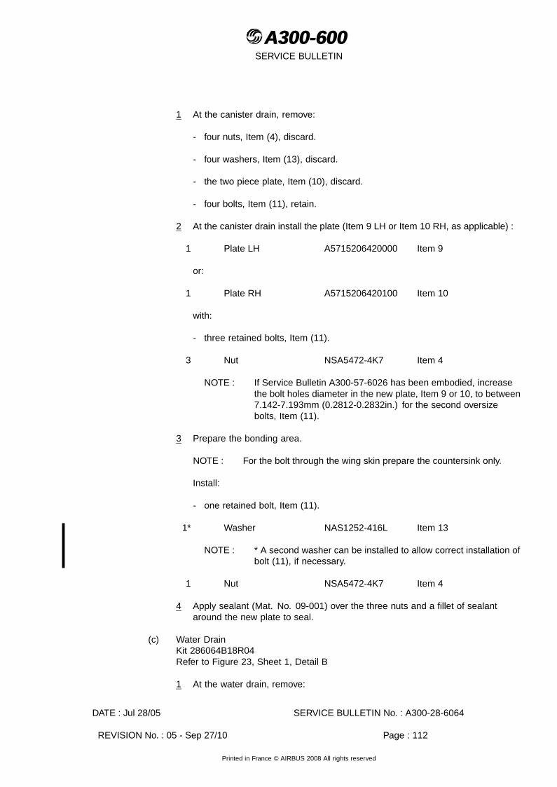
A300-600A300-600SERVICE BULLETIN
1 At the canister drain, remove:
- four nuts, Item (4), discard.
- four washers, Item (13), discard.
- the two piece plate, Item (10), discard.
- four bolts, Item (11), retain.
2 At the canister drain install the plate (Item 9 LH or Item 10 RH, as applicable) :
1 Plate LH A5715206420000 Item 9
or:
1 Plate RH A5715206420100 Item 10
with:
- three retained bolts, Item (11).
3 Nut NSA5472-4K7 Item 4
NOTE : If Service Bulletin A300-57-6026 has been embodied, increasethe bolt holes diameter in the new plate, Item 9 or 10, to between7.142-7.193mm (0.2812-0.2832in.) for the second oversizebolts, Item (11).
3 Prepare the bonding area.
NOTE : For the bolt through the wing skin prepare the countersink only.
Install:
- one retained bolt, Item (11).
1* Washer NAS1252-416L Item 13
NOTE : * A second washer can be installed to allow correct installation ofbolt (11), if necessary.
1 Nut NSA5472-4K7 Item 4
4 Apply sealant (Mat. No. 09-001) over the three nuts and a fillet of sealantaround the new plate to seal.
(c) Water DrainKit 286064B18R04Refer to Figure 23, Sheet 1, Detail B
1 At the water drain, remove:
DATE : Jul 28/05 SERVICE BULLETIN No. : A300-28-6064
REVISION No. : 05 - Sep 27/10 Page : 112
Printed in France © AIRBUS 2008 All rights reserved

A300-600A300-600SERVICE BULLETIN
- one nut, Item (20), discard.
- one bolt, Item (19), retain.
2 At the water drain prepare the bonding area and install:
- one retained bolt, Item (19).
1 Nut NSA5474-4K7 Item 20
(d) Fuel Overflow SensorKit 286064B18R04Refer to Figure 30, Sheet 4
NOTE : Access to Rib Bay 26-27 is also necessary.
1 At the sensor bracket, remove:
- one nut, Item (16), discard.
- one bolt, Item (7), discard.
2 At the sensor bracket prepare the bonding area and install:
1 Bolt NSA5041VBV3-5 Item 71 Nut NSA5474-3K7 Item 16
(e) Overpressure ProtectorKit 286064B18R04Refer to Figure 49, Sheet 1
1 At the flange of the overpressure protector, remove:
- two bolts, Item (30), discard.
2 Prepare the bonding areas and install:
2 Bolt NAS1304-4 Item 30
(26) Wings Fuel Tank Equipment - Rib Bay 1-2 Config. 08 AircraftKit 286064B20R06
(a) Forward Rib Bay Water Drain ValveRefer to Figure 23, Sheet 1, Detail D
1 At the water drain valve, remove:
- one nut, Item (20), discard.
- one bolt, Item (19), retain.
2 At the base of the water drain valve prepare the bonding area.
DATE : Jul 28/05 SERVICE BULLETIN No. : A300-28-6064
REVISION No. : 05 - Sep 27/10 Page : 113
Printed in France © AIRBUS 2008 All rights reserved
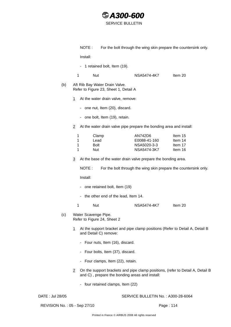
A300-600A300-600SERVICE BULLETIN
NOTE : For the bolt through the wing skin prepare the countersink only.
Install:
- 1 retained bolt, Item (19).
1 Nut NSA5474-4K7 Item 20
(b) Aft Rib Bay Water Drain Valve.Refer to Figure 23, Sheet 1, Detail A
1 At the water drain valve, remove:
- one nut, Item (20), discard.
- one bolt, Item (19), retain.
2 At the water drain valve pipe prepare the bonding area and install:
1 Clamp AN742D6 Item 151 Lead E0088-41-160 Item 141 Bolt NSA5020-3-3 Item 171 Nut NSA5474-3K7 Item 16
3 At the base of the water drain valve prepare the bonding area.
NOTE : For the bolt through the wing skin prepare the countersink only.
Install:
- one retained bolt, Item (19)
- the other end of the lead, Item 14.
1 Nut NSA5474-4K7 Item 20
(c) Water Scavenge Pipe.Refer to Figure 24, Sheet 2
1 At the support bracket and pipe clamp positions (Refer to Detail A, Detail Band Detail C) remove:
- Four nuts, Item (16), discard.
- Four bolts, Item (37), discard.
- Four clamps, Item (22), retain.
2 On the support brackets and pipe clamp positions, (refer to Detail A, Detail Band C) , prepare the bonding areas and install:
- four retained clamps, Item (22)
DATE : Jul 28/05 SERVICE BULLETIN No. : A300-28-6064
REVISION No. : 05 - Sep 27/10 Page : 114
Printed in France © AIRBUS 2008 All rights reserved
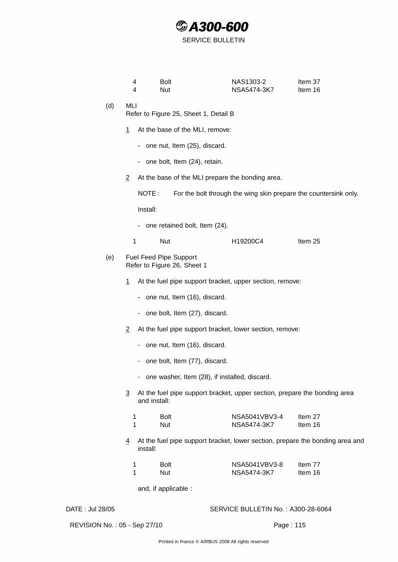
A300-600A300-600SERVICE BULLETIN
4 Bolt NAS1303-2 Item 374 Nut NSA5474-3K7 Item 16
(d) MLIRefer to Figure 25, Sheet 1, Detail B
1 At the base of the MLI, remove:
- one nut, Item (25), discard.
- one bolt, Item (24), retain.
2 At the base of the MLI prepare the bonding area.
NOTE : For the bolt through the wing skin prepare the countersink only.
Install:
- one retained bolt, Item (24).
1 Nut H19200C4 Item 25
(e) Fuel Feed Pipe SupportRefer to Figure 26, Sheet 1
1 At the fuel pipe support bracket, upper section, remove:
- one nut, Item (16), discard.
- one bolt, Item (27), discard.
2 At the fuel pipe support bracket, lower section, remove:
- one nut, Item (16), discard.
- one bolt, Item (77), discard.
- one washer, Item (28), if installed, discard.
3 At the fuel pipe support bracket, upper section, prepare the bonding areaand install:
1 Bolt NSA5041VBV3-4 Item 271 Nut NSA5474-3K7 Item 16
4 At the fuel pipe support bracket, lower section, prepare the bonding area andinstall:
1 Bolt NSA5041VBV3-8 Item 771 Nut NSA5474-3K7 Item 16
and, if applicable :
DATE : Jul 28/05 SERVICE BULLETIN No. : A300-28-6064
REVISION No. : 05 - Sep 27/10 Page : 115
Printed in France © AIRBUS 2008 All rights reserved

A300-600A300-600SERVICE BULLETIN
1 Washer AN960C10L Item 28
(f) Low Fuel Pressure SwitchesRefer to Figure 27, Sheet 1
1 At each pressure switch attachment to the rear spar, remove:
- one nut, Item (16), discard.
- one bolt, Item (34), discard.
2 At the two pressure switch pipes prepare the bonding areas and install:
2 Clamp NSA5519-2B Item 352 Lead E0088-10-100 Item 382 Bolt NAS1303-2 Item 372 Nut NSA5474-3K7 Item 16
3 At the two pressure switch attachments to the rear spar prepare the bondingareas and attach the bonding leads, Item 38, with:
2 Bolt NSA5041VBV3-10 Item 342 Nut NSA5474-3K7 Item 16
4 Torque tighten the bonding lead nuts, Item 16, to between 0.34-0.40 mdaN(30-35 lbf.in.).
(g) Fuel Booster Pump CanistersRefer to Figure 28, Sheet 1
1 At each canister flange, remove from the positions shown in the figure:
- two bolts, Item (45), discard.
CAUTION : BOLTS THAT GO THROUGH THE FAIRING ARE NOT TO BE USEDAS BONDING POINTS.
2 At the two canister flanges prepare the bonding areas.
NOTE : For the bolts through the wing skin prepare the countersinks only.
Install:
4 Bolt NSA5022-4-21 Item 45
3 At each of the fuel pump canisters, adjacent to the existing bonding lead,(refer to Detail C) remove:
- one nut, Item (20), discard.
- one bolt, Item (43), retain.
4 On the two pressure switches pipes prepare the bonding areas and install:
DATE : Jul 28/05 SERVICE BULLETIN No. : A300-28-6064
REVISION No. : 05 - Sep 27/10 Page : 116
Printed in France © AIRBUS 2008 All rights reserved

A300-600A300-600SERVICE BULLETIN
2 Clamp NSA5519-2B Item 352 Lead E0088-41-100 Item 392 Bolt NAS1303-2 Item 372 Nut NSA5474-3K7 Item 16
5 Torque tighten the bonding leads nuts, Item 16, to between 0.34-0.40 mdaN(30-35 lbf.in.).
6 At each of the fuel pump canisters, adjacent to the existing bonding lead, (refer toDetail C) prepare the bonding areas and attach the bonding leads, Item 39, with:
- one retained bolts, Item (43).
2 Nut NSA5474-4K7 Item 20
7 Torque tighten the nut, Item 20 to between 0.68-0.70 mdaN (60-70 lbf.in.).
(h) DiffuserRefer to Figure 29, Sheet 4, Detail B
1 At the diffuser, remove:
- one nut, Item (20), discard.
- one washer, Item (52), discard.
- two bolts, Item (46), discard.
- two washers, Item (53), discard.
2 At the diffuser prepare the bonding areas and install:
2 Bolt NAS1304-3 Item 462 Washer AN960PD416 Item 531 Washer A2824028520000 Item 521 Nut NSA5474-4K7 Item 20
(i) Low Level Fuel SensorRefer to Figure 30, Sheet 3, Detail E
NOTE : It is not necessary to disconnect the sensor for this modification.
1 At the sensor bracket, remove:
- one nut, Item (16), discard
- one washer, Item (74), discard.
- one bolt, Item (17), discard.
2 At the support bracket of the FQI Probe No.2, remove:
- one nut, Item (16), discard.
DATE : Jul 28/05 SERVICE BULLETIN No. : A300-28-6064
REVISION No. : 05 - Sep 27/10 Page : 117
Printed in France © AIRBUS 2008 All rights reserved

A300-600A300-600SERVICE BULLETIN
- one washer, Item (74), discard.
- one bolt, Item (17), discard.
3 At the sensor bracket prepare the bonding area and install:
1 Bolt NSA5020-3-3 Item 171 Washer AN960KD10L Item 741 Nut NSA5474-3K7 Item 16
4 At the support bracket of the FQI Probe No.2 prepare the bonding areas andinstall:
1 Bolt NSA5020-3-3 Item 171 Washer AN960KD10L Item 741 Nut NSA5474-3K7 Item 16
(27) ADDITIONAL WORK on the LH wing tank (Introduced by Rev 01)This additional work is necessary if this Service Bulletin, at the original issue, has beenembodied on aircraft which were not Config. 05 aircraft.
(a) Refuel/Defuel Valve LH Wing - Rib Bay 13-14Kit 286064B39R00Refer to Figure 37, Sheet 1, Sheet 2
1 Get access to Rib Bay 13-14 refer to para 3.A (1) Preparation.
2 If necessary remove and retain the heat shield.
3 On each valve at the front spar, remove:
- one nut, Item (20), discard.
NOTE : Remove and discard any bonding lead tags that may be installedunder the nuts, Item (20).
4 On the valves prepare the bonding areas and install:
2 Lead E0088-41-304 Item 592 Nut NSA5474-4K7 Item 20
5 Torque tighten the nuts, Item 20, to between 0.68-0.79 mdaN (60-70 lbf.in.).
6 At the two bonding lead tag positions on the front spar, attach the bondingleads, Item 59, with:
2 Screw NAS1100-3-7 Item 512 Nut NSA5474-3K7 Item 16
NOTE : It is Mandatory to put the heat shield in its installation position (ifremoved) before you attach the bonding leads, Item 59, to thebonding tags, (Refer to Sheet 2).
DATE : Jul 28/05 SERVICE BULLETIN No. : A300-28-6064
REVISION No. : 05 - Sep 27/10 Page : 118
Printed in France © AIRBUS 2008 All rights reserved

A300-600A300-600SERVICE BULLETIN
7 Torque tighten the nuts, Item 16, to between 0.34-0.40 mdaN (30-35 lbf.in.).
8 Complete the installation of the heat shield.
(28) ADDITIONAL WORK on the center tank (Introduced by Rev 03)
(a) Check the bonding points in the center tank.
NOTE : In Fuel Center Tank, the modification consists in :- Checking the bonding points identified as potentially non conform, Refer to
Figure 50, Sheet 1.For each point identified check the presence of blue coat :
- If blue coat present, no further action.- If no blue coat then :
Measure the electrical resistance between part and the structure, (Referto AMM 20-28-11, Page block 001).
- If the ohmic resistance <10mhm, apply the blue coat.- If the ohmic resistance >10mhm, do the bonding (Refer to AMM
20-28-11, Page block 001).
1 Check the bonding points Item 25 on the rib 1 (LH side).
Refer to Figure 50, Sheet 1, (General location)
Refer to Figure 51, Sheets 1 and 2, (Detailed location)
Refer to Figure 52, Sheet 1, (Result table)
(29) ADDITIONAL WORK on the center tank (For Config 03 aircraft using Kit A03 only)(Introduced by Rev 04)
(a) Install the bonding points.
1 Remove :2 Screw Item (206) Retain2 Washer Item (260) Retain
2 On the blanking plates item (310), do a stripping to the dimension given in thefigure 22, sheets 2 and 3.
3 Temporarily install the bonding lead item 10 on the angle item 12.
4 Temporarily install the angle item 12 on the structure as shown in the figure22, sheets 2 and 3.
5 Drill the structure to match the holes of the angle item 12 at the dimensionsgiven in the figure 22, sheet 3.
6 Install :
DATE : Jul 28/05 SERVICE BULLETIN No. : A300-28-6064
REVISION No. : 05 - Sep 27/10 Page : 119
Printed in France © AIRBUS 2008 All rights reserved

A300-600A300-600SERVICE BULLETIN
2 Angle A9242127720000 Item 12
with
4 Rivet ASNA2050DCJ3215 Item 11
(b) Install :2 Screw Item (206)2 Washer Item (260)2 Bonding Lead E0088-10-200 Item 102 Nut NAS1726-3E Item 52 Bolt NAS1303-3 Item 22 Washer NAS1149F0332P Item 3
NOTE : Items (206) and (260) were retained at removal.
(30) ADDITIONAL WORK on the wings tanks (For Config. 07 aircraft only) (Introduced byRev 04)
(a) Fuel Jettison System - Blanking PlatesKit 286064B25R01 Config. 07 AircraftRefer to Figure 38, Sheet 1, Detail A and B
NOTE : Access to rib bays 13-14 and 15-16 is also necessary.
1 At the blanking plate at rib 14 (refer to Detail A), remove:
- one nut, Item (20), discard.
- one bolt, Item (62), discard.
2 At the blanking plate prepare the bonding area and install:
1 Bolt NSA5041VBV4-6 Item 621 Nut NSA5474-4K7 Item 20
3 At the blanking plate at rib 15 (refer to Detail B), remove:
- one nut, Item (16), discard.
- one bolt, Item (69), discard.
4 At the blanking plate prepare the bonding area and install:
1 Bolt NSA5041VBV3-6 Item 691 Nut NSA5474-3K7 Item 16
(b) Config. 07Rib Bay 17-18Kit 286064B25R01Refer to Figure 38, Sheet 1
1 Get access to Rib Bay 17-18 refer to para 3.A (1) Preparation.
DATE : Jul 28/05 SERVICE BULLETIN No. : A300-28-6064
REVISION No. : 05 - Sep 27/10 Page : 120
Printed in France © AIRBUS 2008 All rights reserved

A300-600A300-600SERVICE BULLETIN
2 Fuel Jettison System Blanking Plates
a At the blanking plates, remove:
- one bolt, Item (66), discard.
- one bolt, Item (68), discard.
- one nut, Item (16), discard.
- one nut, Item (20), discard.
b At the blanking plates prepare the bonding areas and install:
1 Bolt NAS1153-12 Item 661 Nut NSA5474-3K7 Item 161 Bolt NSA5041VBV4-14 Item 681 Nut NSA5474-4K7 Item 20
C. TEST
(1) Wings Fuel Tanks
(a) Do a check of the electrical bonding (Refer to AMM 20-28-11, Page block 001).
NOTE : For maximum permissible resistance values : Refer to the table AMM20-28-11, Page block 001
(b) Preliminary Tests:
1 Initial conditions
a On each connectors that you disconnected, do a visual check as defined byESPM 20-51-10 to make sure that.
- The label of the plug is the same as the label on the receptacle.
- The plug is correctly locked.
2 Do the Functional Test of the Instrument and Panel Integral Lighting (Referto AMM 33-13-00, Page block 501).
3 Do the Operational Test of the Annunciator Light Test (Refer to AMM 33-14-00,Page block 501).
4 Do the Operational Test of the Quantity Indicating System (Refer to AMM28-42-00, Page block 501).
5 Do the test after the Disconnection/Reconnection of plugs 1076VC and 2022VC(If necessary).
(c) After the worksteps in para. D. CLOSE UP, (1) (a) thru (d) have been completed, doa leak test of the wings fuel tanks (Refer to AMM 28-11-00, Page block 501).
DATE : Jul 28/05 SERVICE BULLETIN No. : A300-28-6064
REVISION No. : 05 - Sep 27/10 Page : 121
Printed in France © AIRBUS 2008 All rights reserved

A300-600A300-600SERVICE BULLETIN
NOTE : Fuel leaks are not permitted.
(2) Center Tank
(a) Do a check of the electrical bonding (Refer to AMM 20-28-11, Page block 001).
NOTE : For maximum permissible resistance values : Refer to the table AMM20-28-11, Page block 001
(b) Preliminary Tests:
1 Initial conditions
a On each connectors that you disconnected, do a visual check as defined byESPM 20-51-10 to make sure that.
- The label of the plug is the same as the label on the receptacle.
- The plug is correctly locked.
2 Do the Functional Test of the Instrument and Panel Integral Lighting (Referto AMM 33-13-00, Page block 501).
3 Do the Operational Test of the Annunciator Light Test (Refer to AMM 33-14-00,Page block 501).
4 Do the Operational Test of the Quantity Indicating System (Refer to AMM28-42-00, Page block 501).
5 Do the test after the Disconnection/Reconnection of plugs 1076VC and 2022VC(If necessary).
(c) After the worksteps in para. D. CLOSE UP, (1) (a) thru (d) have been completed, doa leak test of the center fuel tank (Refer to AMM 28-11-00, Page block 501).
NOTE : Fuel leaks are not permitted.
(3) ADDITIONAL WORK on the LH wing (Introduced by Rev 01)
(a) Do a check of the electrical bonding (Refer to AMM 20-28-11, Page block 001).
NOTE : For maximum permissible resistance values : Refer to the table AMM20-28-11, Page block 001
(b) After the worksteps in para. D. CLOSE UP, (2) (a) thru (f) have been completed, do aleak test of the wings fuel tanks (Refer to AMM 28-11-00, Page block 501).
(c) Preliminary Tests:
1 Initial conditions
a On each connectors that you disconnected, do a visual check as defined byESPM 20-51-10 to make sure that.
DATE : Jul 28/05 SERVICE BULLETIN No. : A300-28-6064
REVISION No. : 05 - Sep 27/10 Page : 122
Printed in France © AIRBUS 2008 All rights reserved

A300-600A300-600SERVICE BULLETIN
- The label of the plug is the same as the label on the receptacle.
- The plug is correctly locked.
2 Do the Functional Test of the Instrument and Panel Integral Lighting (Referto AMM 33-13-00, Page block 501).
3 Do the Operational Test of the Annunciator Light Test (Refer to AMM 33-14-00,Page block 501).
4 Do the Operational (BITE) test after the reconnection of plugs 1076VC and2022VC (Refer to AMM 28-42-00, Page block 501).
(4) ADDITIONAL WORK on the center tank (Introduced by Rev 03)
(a) Do a check of the electrical bonding (Refer to AMM 20-28-11, Page block 001).
NOTE : For maximum permissible resistance values : Refer to the table AMM20-28-11, Page block 001
(b) Test
1 Preparation
a Close the access doors 147AZ and 148AZ (Refer to AMM 28-11-29,Page block 401).
b Install the manhole covers (Refer to AMM 28-11-22, Page block 401).
c Refuel the center fuel tank and wing fuel tanks (Refer to AMM 28-25-00,Page block 301).
2 Preliminary Tests:
a Initial conditions
- On each connectors that you disconnected, do a visual check as definedby ESPM 20-51-10 to make sure that.
. The label of the plug is the same as the label on the receptacle.
. The plug is correctly locked.
b Do the Functional Test of the Instrument and Panel Integral Lighting (Referto AMM 33-13-00, Page block 501).
c Do the Operational Test of the Annunciator Light Test (Refer to AMM33-14-00, Page block 501).
(5) ADDITIONAL WORK on the center tank (For Config. 03 aircraft using Kit A03 only)(Introduced by Rev 04)
(a) Do a check of the electrical bonding (Refer to AMM 20-28-11, Page block 001).
DATE : Jul 28/05 SERVICE BULLETIN No. : A300-28-6064
REVISION No. : 05 - Sep 27/10 Page : 123
Printed in France © AIRBUS 2008 All rights reserved
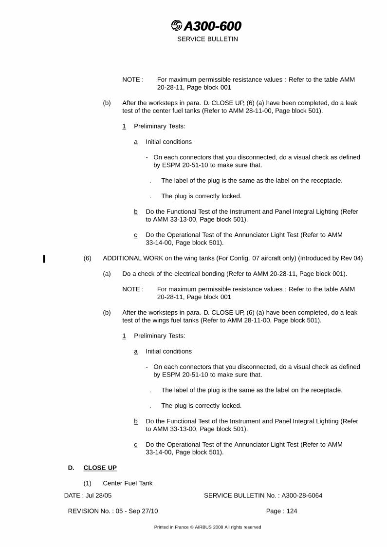
A300-600A300-600SERVICE BULLETIN
NOTE : For maximum permissible resistance values : Refer to the table AMM20-28-11, Page block 001
(b) After the worksteps in para. D. CLOSE UP, (6) (a) have been completed, do a leaktest of the center fuel tanks (Refer to AMM 28-11-00, Page block 501).
1 Preliminary Tests:
a Initial conditions
- On each connectors that you disconnected, do a visual check as definedby ESPM 20-51-10 to make sure that.
. The label of the plug is the same as the label on the receptacle.
. The plug is correctly locked.
b Do the Functional Test of the Instrument and Panel Integral Lighting (Referto AMM 33-13-00, Page block 501).
c Do the Operational Test of the Annunciator Light Test (Refer to AMM33-14-00, Page block 501).
(6) ADDITIONAL WORK on the wing tanks (For Config. 07 aircraft only) (Introduced by Rev 04)
(a) Do a check of the electrical bonding (Refer to AMM 20-28-11, Page block 001).
NOTE : For maximum permissible resistance values : Refer to the table AMM20-28-11, Page block 001
(b) After the worksteps in para. D. CLOSE UP, (6) (a) have been completed, do a leaktest of the wings fuel tanks (Refer to AMM 28-11-00, Page block 501).
1 Preliminary Tests:
a Initial conditions
- On each connectors that you disconnected, do a visual check as definedby ESPM 20-51-10 to make sure that.
. The label of the plug is the same as the label on the receptacle.
. The plug is correctly locked.
b Do the Functional Test of the Instrument and Panel Integral Lighting (Referto AMM 33-13-00, Page block 501).
c Do the Operational Test of the Annunciator Light Test (Refer to AMM33-14-00, Page block 501).
D. CLOSE UP
(1) Center Fuel Tank
DATE : Jul 28/05 SERVICE BULLETIN No. : A300-28-6064
REVISION No. : 05 - Sep 27/10 Page : 124
Printed in France © AIRBUS 2008 All rights reserved

A300-600A300-600SERVICE BULLETIN
(a) Make sure that the work areas are clean and clear of tools and other items ofequipment.
(b) Close the access doors 147AZ and 148AZ (Refer to AMM 28-11-29, Page block 401).
(c) Install the manhole covers (Refer to AMM 28-11-22, Page block 401).
(d) Remove all the warning notices.
(e) Close the Main Landing Gear (MLG) doors (Refer to AMM 32-12-11, Page block 301).
(f) Remove the safety clips and tags and close these circuit breakers :
CAUTION : IF OTHER TANKS HAVE BEEN OPENED ENSURE ALL TANKS ARE CLOSEDBEFORE YOU REMOVE THE SAFETY CLIPS, TAGS AND CLOSE THE CIRCUITBREAKERS.For Aircraft on which Modification No. 04803S5726 (MODIFY COCKPITDESIGN) is embodied.
PANEL DESIGNATION FIN LOCATION
22VU FUEL/TK LO LVL AND CAL/L OUTR &R INR & CTR R
1QJ 208/B26
22VU FUEL/TK LO LVL AND CAL/R OUTR &L INR & CTR L
2QJ 208/B27
132VU FUEL/FUELING HI LVL 6QJ 321/P57132VU FUEL/FUELING OVERFLOW AND CAL 5QJ 321/P58132VU FUEL/FUELING/XFR VALVE 2QU P55132VU FUEL/FQI/SUPPLY AND IND 1QT 321/P59132VU FUEL/FQI/CHAN SUPPLY 1 3QT 321/P60132VU FUEL/FQI/CHAN SUPPLY 2 4QT 321/P61
or
PANEL DESIGNATION FIN LOCATION
22VU FUEL/TK LO LVL/L OUTR & R INR &CTR R
1QJ 208/B26
22VU FUEL/TK LO LVL/R OUTR & L INR &CTR L
2QJ 208/B27
132VU FUEL/FUELING HI LVL 6QJ 321/P57132VU FUEL/FUELING OVERFLOW AND CAL 5QJ 321/P58132VU FUEL/FUELING/XFR VALVE 2QU P55132VU FUEL/FQI/SUPPLY AND IND 1QT 321/P59132VU FUEL/FQI/CHAN SUPPLY 1 3QT 321/P60132VU FUEL/FQI/CHAN SUPPLY 2 4QT 321/P61
For Aircraft on which Modification No. 04803S5726 (MODIFY COCKPIT DESIGN) isnot embodied.
PANEL DESIGNATION FIN LOCATION
22VU FUEL/TK LO LVL/L OUTR & R INR &CTR R
1QJ 208/B26
DATE : Jul 28/05 SERVICE BULLETIN No. : A300-28-6064
REVISION No. : 05 - Sep 27/10 Page : 125
Printed in France © AIRBUS 2008 All rights reserved

A300-600A300-600SERVICE BULLETIN
PANEL DESIGNATION FIN LOCATION
22VU FUEL/TK LO LVL OUTR & L INR & CTR L 2QJ 208/B27128VU FUEL/FUELING HI LVL 6QJ 805/L87128VU FUEL/FUELING OVERFLOW 5QJ 805/L86128VU FUEL/FUELING/TRANSFER VALVE 2QU P55128VU FUEL/FQI/SUPPLY AND IND 1QT 805/L83128VU FUEL/FQI/CHAN SUPPLY 1 3QT 805/L84128VU FUEL/FQI/CHAN SUPPLY 2 4QT 805/L85
(g) Remove the access platforms.
(h) Restore the systems and the aircraft to normal operating condition.
(2) Wings Fuel Tanks
(a) Make sure that the work areas are clean and clear of tools and other items ofequipment.
(b) Install the heat shields (Refer to AMM 57-23-11, Page block 401).
(c) Install the wings fuel tanks manhole covers and access doors/panels (Refer to AMM28-11-22, Page block 401 and AMM 28-11-29, Page block 401).
(d) Remove all the warning notices.
(e) Close the Main Landing Gear (MLG) doors (Refer to AMM 32-12-11, Page block 301).
(f) Refuel the center fuel tank and wing fuel tanks (Refer to AMM 28-25-00, Pageblock 301).
(g) Remove the safety clips and tags and close these circuit breakers :
WARNING : IF OTHER TANKS HAVE BEEN OPENED ENSURE ALL TANKS ARECLOSED BEFORE YOU REMOVE THE SAFETY CLIPS, TAGS ANDCLOSE THE CIRCUIT BREAKERS.
PANEL DESIGNATION FIN LOCATION
22VU FUEL/TK LO LVL AND CAL/L OUTR &R INR & CTR R
1QJ 208/B26
22VU FUEL/TK LO LVL AND CAL/R OUTR &L INR & CTR L
2QJ 208/B27
132VU FUEL/FUELING HI LVL 6QJ 321/P57132VU FUEL/FUELING OVERFLOW AND CAL 5QJ 321/P58132VU FUEL/FUELING/CTL & REFUEL VALVE 1QU 321/P56132VU FUEL/FQI/SUPPLY AND IND 1QT 321/P59132VU FUEL/FQI/CHAN SUPPLY 1 3QT 321/P60132VU FUEL/FQI/CHAN SUPPLY 2 4QT 321/P61
or
DATE : Jul 28/05 SERVICE BULLETIN No. : A300-28-6064
REVISION No. : 05 - Sep 27/10 Page : 126
Printed in France © AIRBUS 2008 All rights reserved
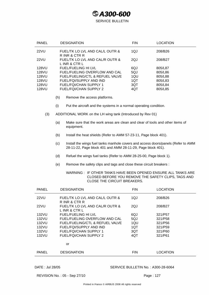
A300-600A300-600SERVICE BULLETIN
PANEL DESIGNATION FIN LOCATION
22VU FUEL/TK LO LVL AND CAL/L OUTR &R INR & CTR R
1QJ 208/B26
22VU FUEL/TK LO LVL AND CAL/R OUTR &L INR & CTR L
2QJ 208/B27
128VU FUEL/FUELING HI LVL 6QJ 805/L87128VU FUEL/FUELING OVERFLOW AND CAL 5QJ 805/L86128VU FUEL/FUELING/CTL & REFUEL VALVE 1QU 805/L88128VU FUEL/FQI/SUPPLY AND IND 1QT 805/L83128VU FUEL/FQI/CHAN SUPPLY 1 3QT 805/L84128VU FUEL/FQI/CHAN SUPPLY 2 4QT 805/L85
(h) Remove the access platforms.
(i) Put the aircraft and the systems in a normal operating condition.
(3) ADDITIONAL WORK on the LH wing tank (Introduced by Rev 01)
(a) Make sure that the work areas are clean and clear of tools and other items ofequipment.
(b) Install the heat shields (Refer to AMM 57-23-11, Page block 401).
(c) Install the wings fuel tanks manhole covers and access doors/panels (Refer to AMM28-11-22, Page block 401 and AMM 28-11-29, Page block 401).
(d) Refuel the wings fuel tanks (Refer to AMM 28-25-00, Page block 1).
(e) Remove the safety clips and tags and close these circuit breakers :
WARNING : IF OTHER TANKS HAVE BEEN OPENED ENSURE ALL TANKS ARECLOSED BEFORE YOU REMOVE THE SAFETY CLIPS, TAGS ANDCLOSE THE CIRCUIT BREAKERS.
PANEL DESIGNATION FIN LOCATION
22VU FUEL/TK LO LVL AND CAL/L OUTR &R INR & CTR R
1QJ 208/B26
22VU FUEL/TK LO LVL AND CAL/R OUTR &L INR & CTR L
2QJ 208/B27
132VU FUEL/FUELING HI LVL 6QJ 321/P57132VU FUEL/FUELING OVERFLOW AND CAL 5QJ 321/P58132VU FUEL/FUELING/CTL & REFUEL VALVE 1QU 321/P56132VU FUEL/FQI/SUPPLY AND IND 1QT 321/P59132VU FUEL/FQI/CHAN SUPPLY 1 3QT 321/P60132VU FUEL/FQI/CHAN SUPPLY 2 4QT 321/P61
or
PANEL DESIGNATION FIN LOCATION
DATE : Jul 28/05 SERVICE BULLETIN No. : A300-28-6064
REVISION No. : 05 - Sep 27/10 Page : 127
Printed in France © AIRBUS 2008 All rights reserved

A300-600A300-600SERVICE BULLETIN
PANEL DESIGNATION FIN LOCATION
22VU FUEL/TK LO LVL AND CAL/L OUTR &R INR & CTR R
1QJ 208/B26
22VU FUEL/TK LO LVL AND CAL/R OUTR &L INR & CTR L
2QJ 208/B27
128VU FUEL/FUELING HI LVL 6QJ 805/L87128VU FUEL/FUELING OVERFLOW AND CAL 5QJ 805/L86128VU FUEL/FUELING/CTL & REFUEL VALVE 1QU 805/L88128VU FUEL/FQI/SUPPLY AND IND 1QT 805/L83128VU FUEL/FQI/CHAN SUPPLY 1 3QT 805/L84128VU FUEL/FQI/CHAN SUPPLY 2 4QT 805/L85
(f) Remove the access platforms.
(g) Put the aircraft and the systems in a normal operating condition.
(4) ADDITIONAL WORK on the center tank (Introduced by Rev 03)
(a) Close-up
1 Make sure that the work areas are clean and clear of tools and other itemsof equipment.
2 Remove all the warning notices.
3 Close the Main Landing Gear (MLG) doors (Refer to AMM 32-12-11, Pageblock 301).
4 Remove the safety clips and tags and close these circuit breakers:
WARNING : IF OTHER TANKS HAVE BEEN OPENED ENSURE ALL TANKS ARE CLOSEDBEFORE YOU REMOVE THE SAFETY CLIPS, TAGS AND CLOSE THECIRCUIT BREAKERS.Depending on aircraft configuration
PANEL DESIGNATION FIN LOCATION
22VU FUEL/TK LO LVL AND CAL/L OUTR &R INR & CTR R
1QJ 208/B26
22VU FUEL/TK LO LVL AND CAL/R OUTR &L INR & CTR L
2QJ 208/B27
132VU FUEL/FUELING HI LVL 6QJ 321/P57132VU FUEL/FUELING OVERFLOW AND CAL 5QJ 321/P58132VU FUEL/FUELING/CTL & REFUEL VALVE 1QU 321/P56132VU FUEL/FQI/SUPPLY AND IND 1QT 321/P59132VU FUEL/FQI/CHAN SUPPLY 1 3QT 321/P60132VU FUEL/FQI/CHAN SUPPLY 2 4QT 321/P61
or
PANEL DESIGNATION FIN LOCATION
DATE : Jul 28/05 SERVICE BULLETIN No. : A300-28-6064
REVISION No. : 05 - Sep 27/10 Page : 128
Printed in France © AIRBUS 2008 All rights reserved

A300-600A300-600SERVICE BULLETIN
PANEL DESIGNATION FIN LOCATION
22VU FUEL/TK LO LVL AND CAL/L OUTR &R INR & CTR R
1QJ 208/B26
22VU FUEL/TK LO LVL AND CAL/R OUTR &L INR & CTR L
2QJ 208/B27
128VU FUEL/FUELING HI LVL 6QJ 805/L87128VU FUEL/FUELING OVERFLOW AND CAL 5QJ 805/L86128VU FUEL/FUELING/CTL & REFUEL VALVE 1QU 805/L88128VU FUEL/FQI/SUPPLY AND IND 1QT 805/L83128VU FUEL/FQI/CHAN SUPPLY 1 3QT 805/L84128VU FUEL/FQI/CHAN SUPPLY 2 4QT 805/L85
5 Remove the access platforms.
6 Restore the systems and the aircraft to normal operating condition.
(5) ADDITIONAL WORK on the center tank (For aircraft using Kit A03 only) (Introduced byRev 04)
(a) Make sure that the work areas are clean and clear of tools and other items ofequipment.
(b) Install the heat shields (Refer to AMM 57-23-11, Page block 401).
(c) Install the wings fuel tanks manhole covers and access doors/panels (Refer to AMM28-11-22, Page block 401 and AMM 28-11-29, Page block 401).
(d) Remove the safety clips and tags and close these circuit breakers:
CAUTION : IF OTHER TANKS HAVE BEEN OPENED ENSURE ALL TANKS ARE CLOSEDBEFORE YOU REMOVE THE SAFETY CLIPS, TAGS AND CLOSE THE CIRCUITBREAKERS.Depending on aircraft configuration
PANEL DESIGNATION FIN LOCATION
22VU FUEL/TK LO LVL AND CAL/L OUTR &R INR & CTR R
1QJ 208/B26
22VU FUEL/TK LO LVL AND CAL/R OUTR &L INR & CTR L
2QJ 208/B27
132VU FUEL/FUELING HI LVL 6QJ 321/P57132VU FUEL/FUELING OVERFLOW AND CAL 5QJ 321/P58132VU FUEL/FUELING/CTL & REFUEL VALVE 1QU 321/P56132VU FUEL/FQI/SUPPLY AND IND 1QT 321/P59132VU FUEL/FQI/CHAN SUPPLY 1 3QT 321/P60132VU FUEL/FQI/CHAN SUPPLY 2 4QT 321/P61
or
PANEL DESIGNATION FIN LOCATION
22VU FUEL/TK LO LVL AND CAL/L OUTR &R INR & CTR R
1QJ 208/B26
DATE : Jul 28/05 SERVICE BULLETIN No. : A300-28-6064
REVISION No. : 05 - Sep 27/10 Page : 129
Printed in France © AIRBUS 2008 All rights reserved

A300-600A300-600SERVICE BULLETIN
PANEL DESIGNATION FIN LOCATION
22VU FUEL/TK LO LVL AND CAL/R OUTR &L INR & CTR L
2QJ 208/B27
128VU FUEL/FUELING HI LVL 6QJ 805/L87128VU FUEL/FUELING OVERFLOW AND CAL 5QJ 805/L86128VU FUEL/FUELING/CTL & REFUEL VALVE 1QU 805/L88128VU FUEL/FQI/SUPPLY AND IND 1QT 805/L83128VU FUEL/FQI/CHAN SUPPLY 1 3QT 805/L84128VU FUEL/FQI/CHAN SUPPLY 2 4QT 805/L85
(e) Refuel the wings fuel tanks (Refer to AMM 28-25-00, Page block 1).
(f) Remove the access platforms.
(g) Put the aircraft and the systems in a normal operating condition.
(6) ADDITIONAL WORK on the wing tanks (For Config. 07 aircraft only) (Introduced by Rev 04)
(a) Close-up
1 Make sure that the work areas are clean and clear of tools and other itemsof equipment.
2 Install wing manhole covers as necessary (Refer to AMM 28-11-22, Pageblock 401).
3 Remove all the warning notices.
4 Remove the safety clips and tags and close these circuit breakers:
For Aircraft on which Modification No. 04803S5726 (MODIFY COCKPITDESIGN) is embodied.
PANEL DESIGNATION FIN LOCATION
22VU FUEL/TK LO LVL AND CAL/L OUTR &R INR & CTR R
1QJ 208/B26
22VU FUEL/TK LO LVL AND CAL/R OUTR &L INR & CTR L
2QJ 208/B27
132VU FUEL/FUELING HI LVL 6QJ 321/P57132VU FUEL/FUELING OVERFLOW AND CAL 5QJ 321/P58132VU FUEL/FUELING/XFR VALVE 2QU P55132VU FUEL/FQI/SUPPLY AND IND 1QT 321/P59132VU FUEL/FQI/CHAN SUPPLY 1 3QT 321/P60132VU FUEL/FQI/CHAN SUPPLY 2 4QT 321/P61
or
PANEL DESIGNATION FIN LOCATION
DATE : Jul 28/05 SERVICE BULLETIN No. : A300-28-6064
REVISION No. : 05 - Sep 27/10 Page : 130
Printed in France © AIRBUS 2008 All rights reserved
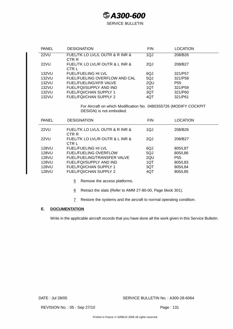
A300-600A300-600SERVICE BULLETIN
PANEL DESIGNATION FIN LOCATION
22VU FUEL/TK LO LVL/L OUTR & R INR &CTR R
1QJ 208/B26
22VU FUEL/TK LO LVL/R OUTR & L INR &CTR L
2QJ 208/B27
132VU FUEL/FUELING HI LVL 6QJ 321/P57132VU FUEL/FUELING OVERFLOW AND CAL 5QJ 321/P58132VU FUEL/FUELING/XFR VALVE 2QU P55132VU FUEL/FQI/SUPPLY AND IND 1QT 321/P59132VU FUEL/FQI/CHAN SUPPLY 1 3QT 321/P60132VU FUEL/FQI/CHAN SUPPLY 2 4QT 321/P61
For Aircraft on which Modification No. 04803S5726 (MODIFY COCKPITDESIGN) is not embodied.
PANEL DESIGNATION FIN LOCATION
22VU FUEL/TK LO LVL/L OUTR & R INR &CTR R
1QJ 208/B26
22VU FUEL/TK LO LVL/R OUTR & L INR &CTR L
2QJ 208/B27
128VU FUEL/FUELING HI LVL 6QJ 805/L87128VU FUEL/FUELING OVERFLOW 5QJ 805/L86128VU FUEL/FUELING/TRANSFER VALVE 2QU P55128VU FUEL/FQI/SUPPLY AND IND 1QT 805/L83128VU FUEL/FQI/CHAN SUPPLY 1 3QT 805/L84128VU FUEL/FQI/CHAN SUPPLY 2 4QT 805/L85
5 Remove the access platforms.
6 Retract the slats (Refer to AMM 27-80-00, Page block 301).
7 Restore the systems and the aircraft to normal operating condition.
E. DOCUMENTATION
Write in the applicable aircraft records that you have done all the work given in this Service Bulletin.
DATE : Jul 28/05 SERVICE BULLETIN No. : A300-28-6064
REVISION No. : 05 - Sep 27/10 Page : 131
Printed in France © AIRBUS 2008 All rights reserved

A300-600A300-600SERVICE BULLETIN
Figure 1, Sheet 1Decomposition of the Center TankDATE : Jul 28/05 SERVICE BULLETIN No. : A300-28-6064
REVISION No. : 05 - Sep 27/10 Page : 132
Printed in France © AIRBUS 2008 All rights reserved
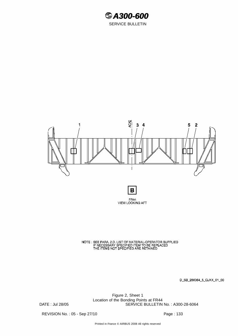
A300-600A300-600SERVICE BULLETIN
Figure 2, Sheet 1Location of the Bonding Points at FR44
DATE : Jul 28/05 SERVICE BULLETIN No. : A300-28-6064
REVISION No. : 05 - Sep 27/10 Page : 133
Printed in France © AIRBUS 2008 All rights reserved
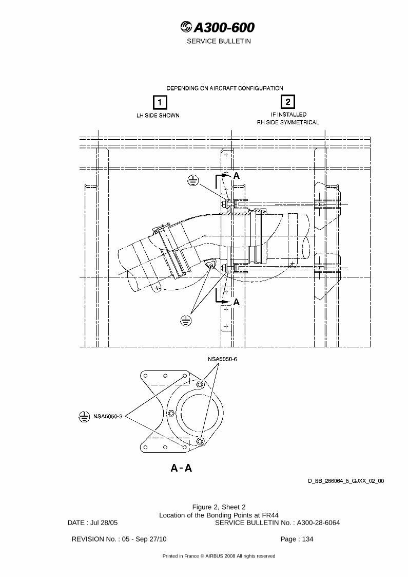
A300-600A300-600SERVICE BULLETIN
Figure 2, Sheet 2Location of the Bonding Points at FR44
DATE : Jul 28/05 SERVICE BULLETIN No. : A300-28-6064
REVISION No. : 05 - Sep 27/10 Page : 134
Printed in France © AIRBUS 2008 All rights reserved

A300-600A300-600SERVICE BULLETIN
Figure 2, Sheet 3Location of the Bonding Points at FR44
DATE : Jul 28/05 SERVICE BULLETIN No. : A300-28-6064
REVISION No. : 05 - Sep 27/10 Page : 135
Printed in France © AIRBUS 2008 All rights reserved

A300-600A300-600SERVICE BULLETIN
Figure 2, Sheet 4Location of the Bonding Points at FR44
DATE : Jul 28/05 SERVICE BULLETIN No. : A300-28-6064
REVISION No. : 05 - Sep 27/10 Page : 136
Printed in France © AIRBUS 2008 All rights reserved

A300-600A300-600SERVICE BULLETIN
Figure 2, Sheet 5Location of the Bonding Points at FR44
DATE : Jul 28/05 SERVICE BULLETIN No. : A300-28-6064
REVISION No. : 05 - Sep 27/10 Page : 137
Printed in France © AIRBUS 2008 All rights reserved
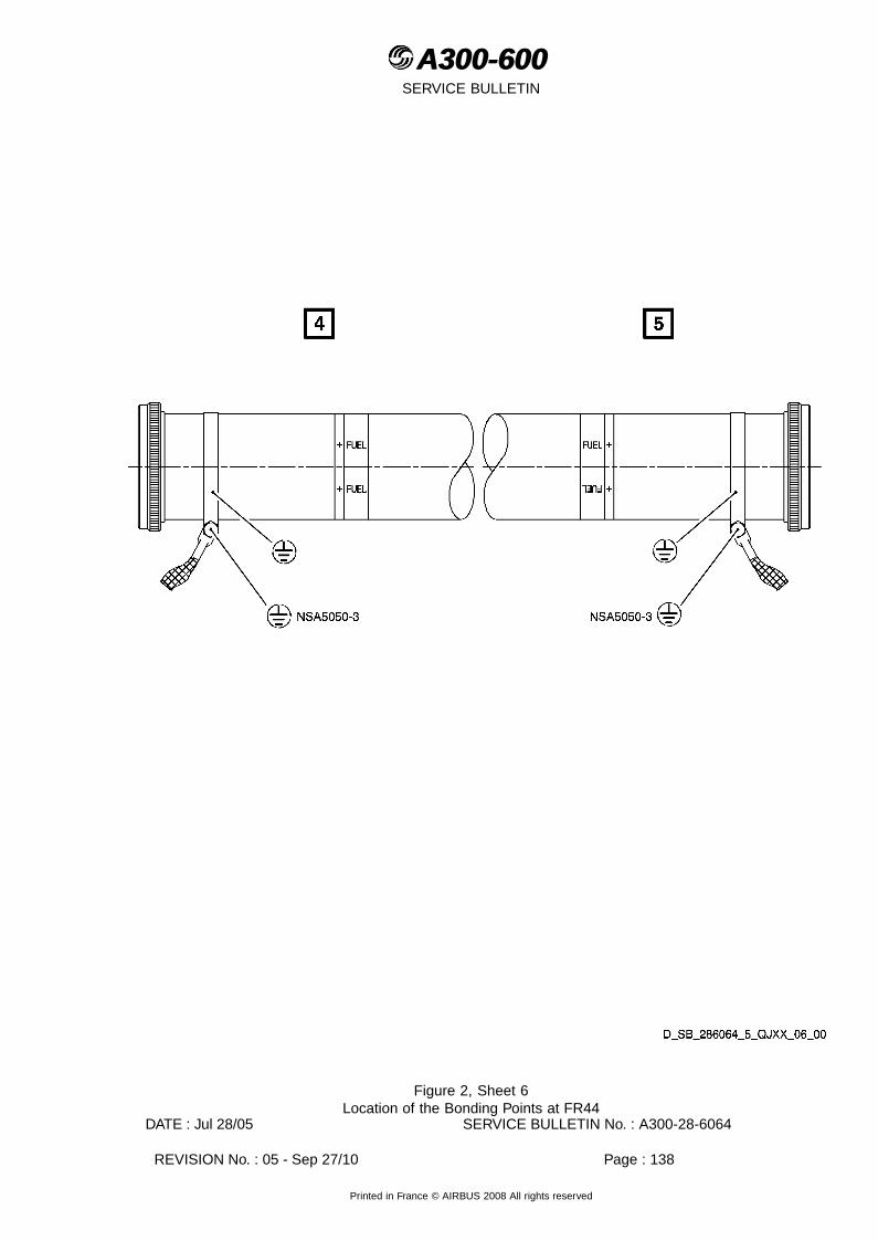
A300-600A300-600SERVICE BULLETIN
Figure 2, Sheet 6Location of the Bonding Points at FR44
DATE : Jul 28/05 SERVICE BULLETIN No. : A300-28-6064
REVISION No. : 05 - Sep 27/10 Page : 138
Printed in France © AIRBUS 2008 All rights reserved

A300-600A300-600SERVICE BULLETIN
Figure 3, Sheet 1Bonding Points to Check at FR44
DATE : Jul 28/05 SERVICE BULLETIN No. : A300-28-6064
REVISION No. : 05 - Sep 27/10 Page : 139
Printed in France © AIRBUS 2008 All rights reserved

A300-600A300-600SERVICE BULLETIN
Figure 4, Sheet 1Location of the Bonding Points at FR47
DATE : Jul 28/05 SERVICE BULLETIN No. : A300-28-6064
REVISION No. : 05 - Sep 27/10 Page : 140
Printed in France © AIRBUS 2008 All rights reserved
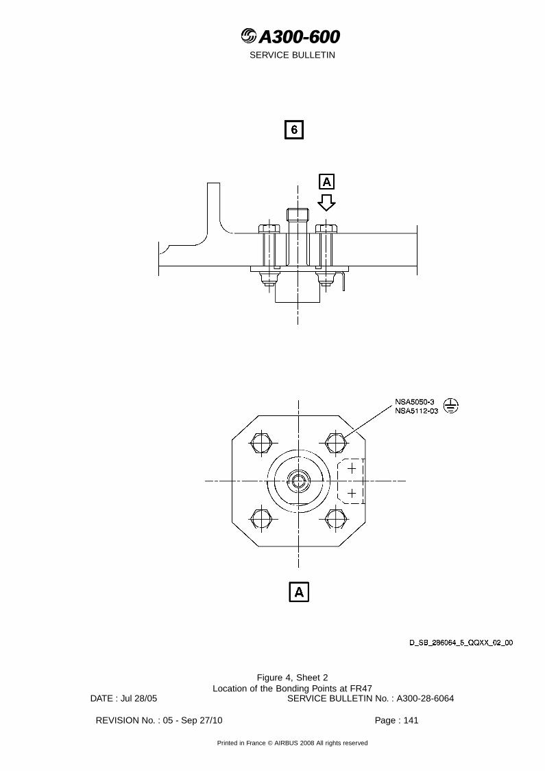
A300-600A300-600SERVICE BULLETIN
Figure 4, Sheet 2Location of the Bonding Points at FR47
DATE : Jul 28/05 SERVICE BULLETIN No. : A300-28-6064
REVISION No. : 05 - Sep 27/10 Page : 141
Printed in France © AIRBUS 2008 All rights reserved

A300-600A300-600SERVICE BULLETIN
Figure 4, Sheet 3Location of the Bonding Points at FR47
DATE : Jul 28/05 SERVICE BULLETIN No. : A300-28-6064
REVISION No. : 05 - Sep 27/10 Page : 142
Printed in France © AIRBUS 2008 All rights reserved
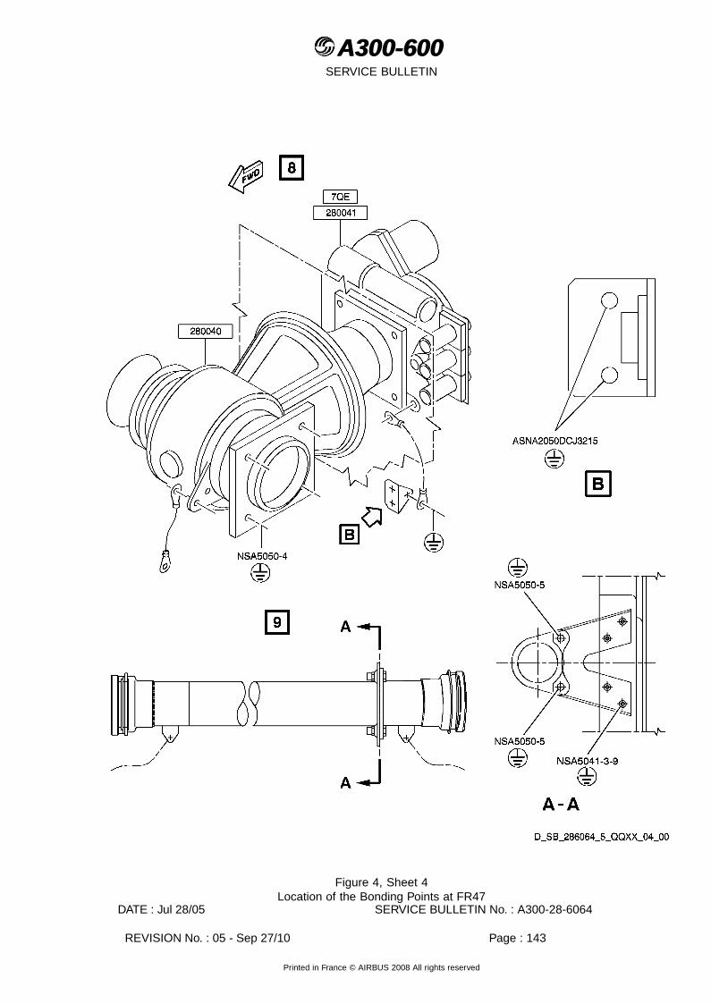
A300-600A300-600SERVICE BULLETIN
Figure 4, Sheet 4Location of the Bonding Points at FR47
DATE : Jul 28/05 SERVICE BULLETIN No. : A300-28-6064
REVISION No. : 05 - Sep 27/10 Page : 143
Printed in France © AIRBUS 2008 All rights reserved

A300-600A300-600SERVICE BULLETIN
Figure 4, Sheet 5Location of the Bonding Points at FR47
DATE : Jul 28/05 SERVICE BULLETIN No. : A300-28-6064
REVISION No. : 05 - Sep 27/10 Page : 144
Printed in France © AIRBUS 2008 All rights reserved
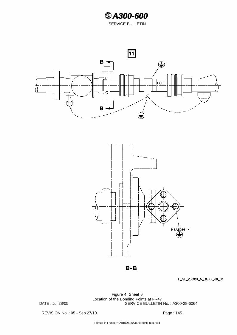
A300-600A300-600SERVICE BULLETIN
Figure 4, Sheet 6Location of the Bonding Points at FR47
DATE : Jul 28/05 SERVICE BULLETIN No. : A300-28-6064
REVISION No. : 05 - Sep 27/10 Page : 145
Printed in France © AIRBUS 2008 All rights reserved

A300-600A300-600SERVICE BULLETIN
Figure 4, Sheet 7Location of the Bonding Points at FR47
DATE : Jul 28/05 SERVICE BULLETIN No. : A300-28-6064
REVISION No. : 05 - Sep 27/10 Page : 146
Printed in France © AIRBUS 2008 All rights reserved

A300-600A300-600SERVICE BULLETIN
Figure 4, Sheet 8Location of the Bonding Points at FR47
DATE : Jul 28/05 SERVICE BULLETIN No. : A300-28-6064
REVISION No. : 05 - Sep 27/10 Page : 147
Printed in France © AIRBUS 2008 All rights reserved

A300-600A300-600SERVICE BULLETIN
Figure 4, Sheet 9Location of the Bonding Points at FR47
DATE : Jul 28/05 SERVICE BULLETIN No. : A300-28-6064
REVISION No. : 05 - Sep 27/10 Page : 148
Printed in France © AIRBUS 2008 All rights reserved
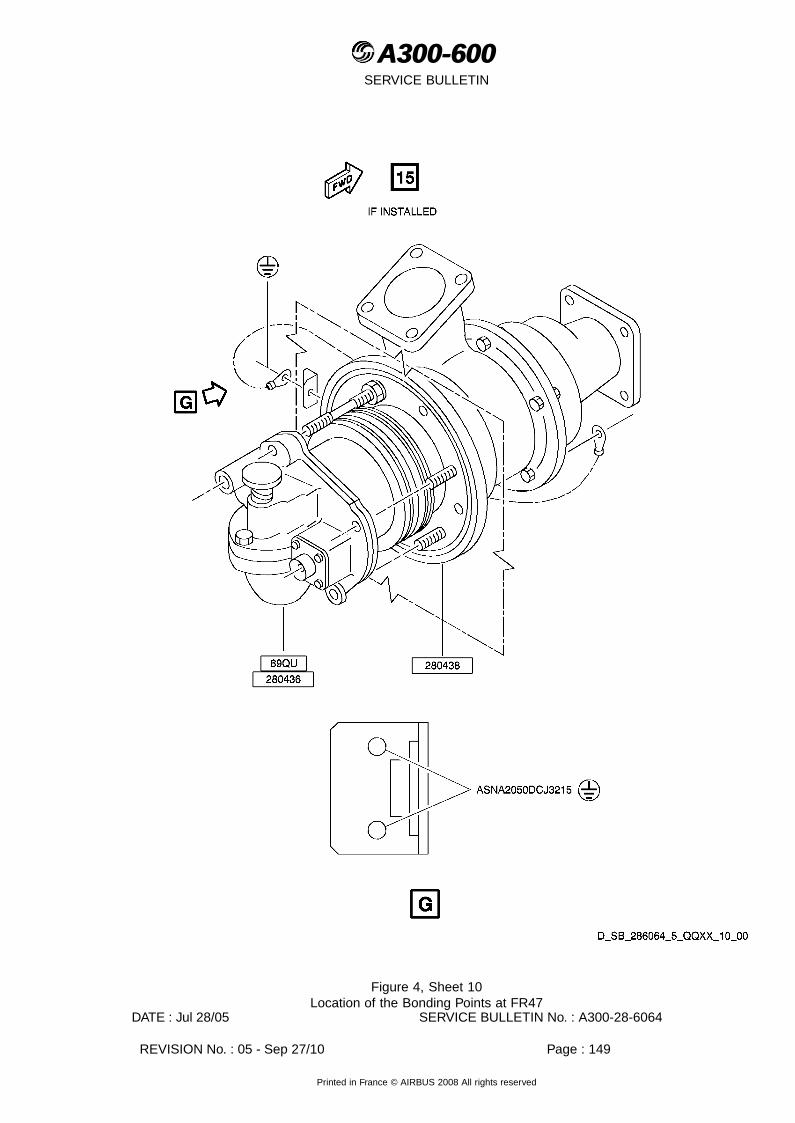
A300-600A300-600SERVICE BULLETIN
Figure 4, Sheet 10Location of the Bonding Points at FR47
DATE : Jul 28/05 SERVICE BULLETIN No. : A300-28-6064
REVISION No. : 05 - Sep 27/10 Page : 149
Printed in France © AIRBUS 2008 All rights reserved

A300-600A300-600SERVICE BULLETIN
Figure 4, Sheet 11Location of the Bonding Points at FR47
DATE : Jul 28/05 SERVICE BULLETIN No. : A300-28-6064
REVISION No. : 05 - Sep 27/10 Page : 150
Printed in France © AIRBUS 2008 All rights reserved

A300-600A300-600SERVICE BULLETIN
Figure 4, Sheet 12Location of the Bonding Points at FR47
DATE : Jul 28/05 SERVICE BULLETIN No. : A300-28-6064
REVISION No. : 05 - Sep 27/10 Page : 151
Printed in France © AIRBUS 2008 All rights reserved

A300-600A300-600SERVICE BULLETIN
Figure 4, Sheet 13Location of the Bonding Points at FR47
DATE : Jul 28/05 SERVICE BULLETIN No. : A300-28-6064
REVISION No. : 05 - Sep 27/10 Page : 152
Printed in France © AIRBUS 2008 All rights reserved

A300-600A300-600SERVICE BULLETIN
Figure 4, Sheet 14Location of the Bonding Points at FR47
DATE : Jul 28/05 SERVICE BULLETIN No. : A300-28-6064
REVISION No. : 05 - Sep 27/10 Page : 153
Printed in France © AIRBUS 2008 All rights reserved

A300-600A300-600SERVICE BULLETIN
Figure 4, Sheet 15Location of the Bonding Points at FR47
DATE : Jul 28/05 SERVICE BULLETIN No. : A300-28-6064
REVISION No. : 05 - Sep 27/10 Page : 154
Printed in France © AIRBUS 2008 All rights reserved

A300-600A300-600SERVICE BULLETIN
Figure 4, Sheet 16Location of the Bonding Points at FR47
DATE : Jul 28/05 SERVICE BULLETIN No. : A300-28-6064
REVISION No. : 05 - Sep 27/10 Page : 155
Printed in France © AIRBUS 2008 All rights reserved

A300-600A300-600SERVICE BULLETIN
Figure 4, Sheet 17Location of the Bonding Points at FR47
DATE : Jul 28/05 SERVICE BULLETIN No. : A300-28-6064
REVISION No. : 05 - Sep 27/10 Page : 156
Printed in France © AIRBUS 2008 All rights reserved

A300-600A300-600SERVICE BULLETIN
Figure 5, Sheet 1Bonding Points to Check at FR47
DATE : Jul 28/05 SERVICE BULLETIN No. : A300-28-6064
REVISION No. : 05 - Sep 27/10 Page : 157
Printed in France © AIRBUS 2008 All rights reserved

A300-600A300-600SERVICE BULLETIN
Figure 6, Sheet 1Location of the Bonding Points on the Rib 1 (LH side)
DATE : Jul 28/05 SERVICE BULLETIN No. : A300-28-6064
REVISION No. : 05 - Sep 27/10 Page : 158
Printed in France © AIRBUS 2008 All rights reserved

A300-600A300-600SERVICE BULLETIN
Figure 6, Sheet 2Location of the Bonding Points on the Rib 1 (LH side)
DATE : Jul 28/05 SERVICE BULLETIN No. : A300-28-6064
REVISION No. : 05 - Sep 27/10 Page : 159
Printed in France © AIRBUS 2008 All rights reserved
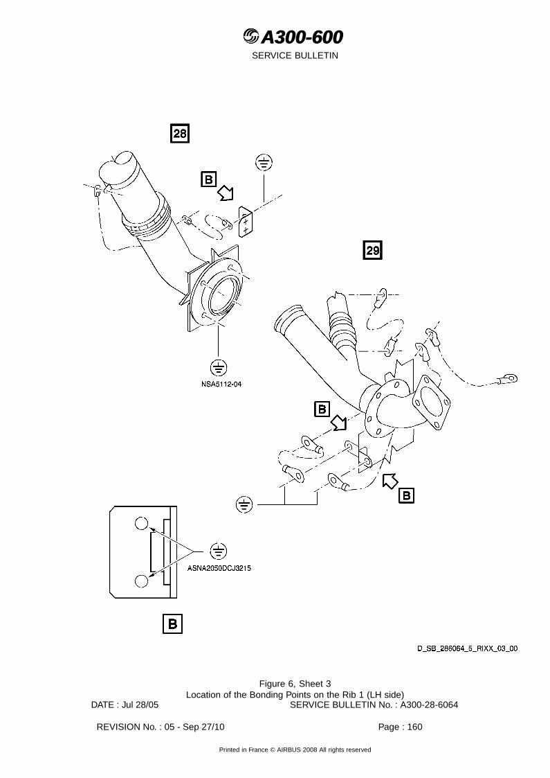
A300-600A300-600SERVICE BULLETIN
Figure 6, Sheet 3Location of the Bonding Points on the Rib 1 (LH side)
DATE : Jul 28/05 SERVICE BULLETIN No. : A300-28-6064
REVISION No. : 05 - Sep 27/10 Page : 160
Printed in France © AIRBUS 2008 All rights reserved
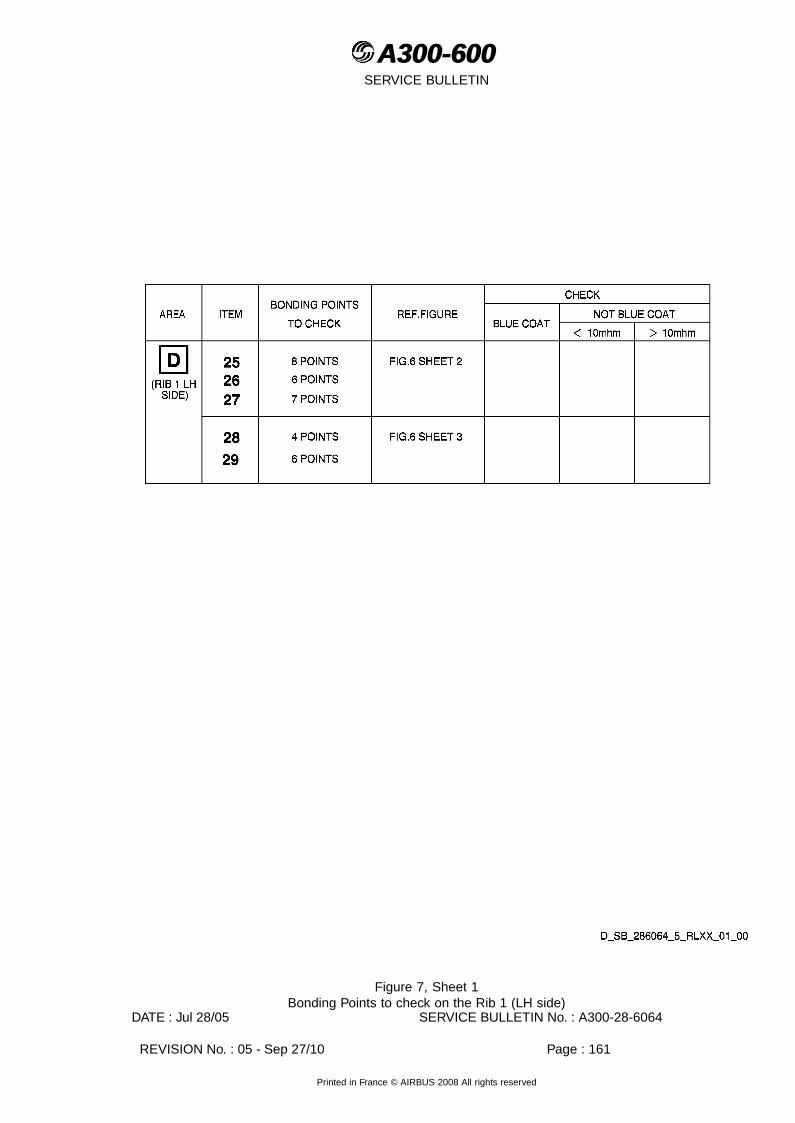
A300-600A300-600SERVICE BULLETIN
Figure 7, Sheet 1Bonding Points to check on the Rib 1 (LH side)
DATE : Jul 28/05 SERVICE BULLETIN No. : A300-28-6064
REVISION No. : 05 - Sep 27/10 Page : 161
Printed in France © AIRBUS 2008 All rights reserved

A300-600A300-600SERVICE BULLETIN
Figure 8, Sheet 1Location of the Bonding Points on the Intrados Panel
DATE : Jul 28/05 SERVICE BULLETIN No. : A300-28-6064
REVISION No. : 05 - Sep 27/10 Page : 162
Printed in France © AIRBUS 2008 All rights reserved
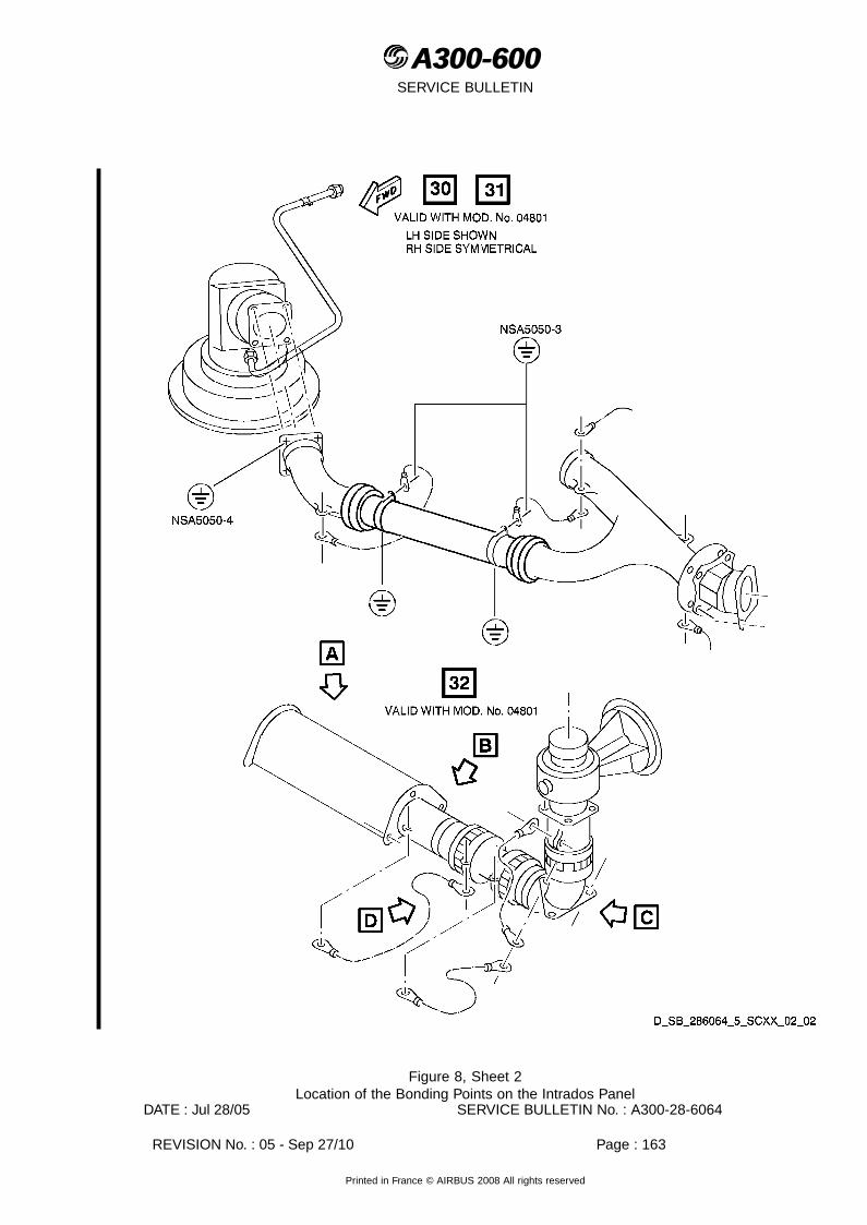
A300-600A300-600SERVICE BULLETIN
Figure 8, Sheet 2Location of the Bonding Points on the Intrados Panel
DATE : Jul 28/05 SERVICE BULLETIN No. : A300-28-6064
REVISION No. : 05 - Sep 27/10 Page : 163
Printed in France © AIRBUS 2008 All rights reserved

A300-600A300-600SERVICE BULLETIN
Figure 8, Sheet 3Location of the Bonding Points on the Intrados Panel
DATE : Jul 28/05 SERVICE BULLETIN No. : A300-28-6064
REVISION No. : 05 - Sep 27/10 Page : 164
Printed in France © AIRBUS 2008 All rights reserved

A300-600A300-600SERVICE BULLETIN
Figure 8, Sheet 4Location of the Bonding Points on the Intrados Panel
DATE : Jul 28/05 SERVICE BULLETIN No. : A300-28-6064
REVISION No. : 05 - Sep 27/10 Page : 165
Printed in France © AIRBUS 2008 All rights reserved

A300-600A300-600SERVICE BULLETIN
Figure 8, Sheet 5Location of the Bonding Points on the Intrados Panel
DATE : Jul 28/05 SERVICE BULLETIN No. : A300-28-6064
REVISION No. : 05 - Sep 27/10 Page : 166
Printed in France © AIRBUS 2008 All rights reserved

A300-600A300-600SERVICE BULLETIN
Figure 8, Sheet 6Location of the Bonding Points on the Intrados Panel
DATE : Jul 28/05 SERVICE BULLETIN No. : A300-28-6064
REVISION No. : 05 - Sep 27/10 Page : 167
Printed in France © AIRBUS 2008 All rights reserved
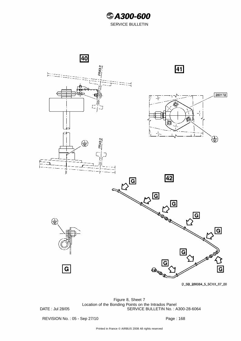
A300-600A300-600SERVICE BULLETIN
Figure 8, Sheet 7Location of the Bonding Points on the Intrados Panel
DATE : Jul 28/05 SERVICE BULLETIN No. : A300-28-6064
REVISION No. : 05 - Sep 27/10 Page : 168
Printed in France © AIRBUS 2008 All rights reserved

A300-600A300-600SERVICE BULLETIN
Figure 8, Sheet 8Location of the Bonding Points on the Intrados Panel
DATE : Jul 28/05 SERVICE BULLETIN No. : A300-28-6064
REVISION No. : 05 - Sep 27/10 Page : 169
Printed in France © AIRBUS 2008 All rights reserved

A300-600A300-600SERVICE BULLETIN
Figure 8, Sheet 9Location of the Bonding Points on the Intrados Panel
DATE : Jul 28/05 SERVICE BULLETIN No. : A300-28-6064
REVISION No. : 05 - Sep 27/10 Page : 170
Printed in France © AIRBUS 2008 All rights reserved

A300-600A300-600SERVICE BULLETIN
Figure 8, Sheet 10Location of the Bonding Points on the Intrados Panel
DATE : Jul 28/05 SERVICE BULLETIN No. : A300-28-6064
REVISION No. : 05 - Sep 27/10 Page : 171
Printed in France © AIRBUS 2008 All rights reserved

A300-600A300-600SERVICE BULLETIN
Figure 9, Sheet 1Bonding Points to check on the Intrados Panel
DATE : Jul 28/05 SERVICE BULLETIN No. : A300-28-6064
REVISION No. : 05 - Sep 27/10 Page : 172
Printed in France © AIRBUS 2008 All rights reserved
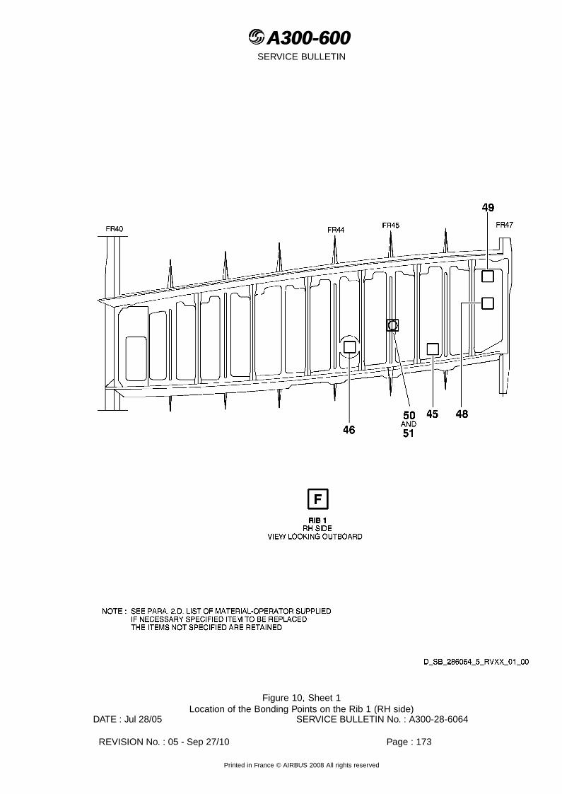
A300-600A300-600SERVICE BULLETIN
Figure 10, Sheet 1Location of the Bonding Points on the Rib 1 (RH side)
DATE : Jul 28/05 SERVICE BULLETIN No. : A300-28-6064
REVISION No. : 05 - Sep 27/10 Page : 173
Printed in France © AIRBUS 2008 All rights reserved

A300-600A300-600SERVICE BULLETIN
Figure 10, Sheet 2Location of the Bonding Points on the Rib 1 (RH side)
DATE : Jul 28/05 SERVICE BULLETIN No. : A300-28-6064
REVISION No. : 05 - Sep 27/10 Page : 174
Printed in France © AIRBUS 2008 All rights reserved

A300-600A300-600SERVICE BULLETIN
Figure 10, Sheet 3Location of the Bonding Points on the Rib 1 (RH side)
DATE : Jul 28/05 SERVICE BULLETIN No. : A300-28-6064
REVISION No. : 05 - Sep 27/10 Page : 175
Printed in France © AIRBUS 2008 All rights reserved
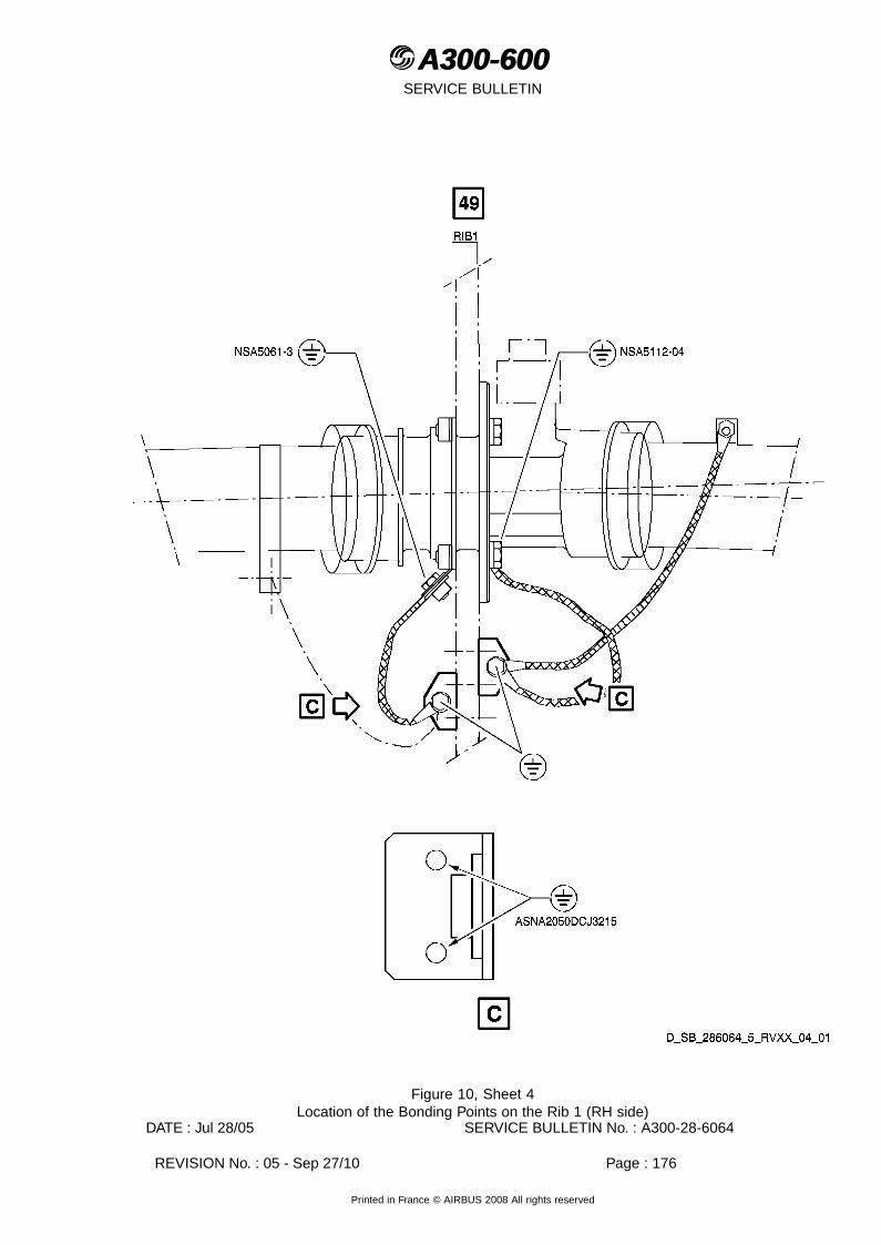
A300-600A300-600SERVICE BULLETIN
Figure 10, Sheet 4Location of the Bonding Points on the Rib 1 (RH side)
DATE : Jul 28/05 SERVICE BULLETIN No. : A300-28-6064
REVISION No. : 05 - Sep 27/10 Page : 176
Printed in France © AIRBUS 2008 All rights reserved

A300-600A300-600SERVICE BULLETIN
Figure 10, Sheet 5Location of the Bonding Points on the Rib 1 (RH side)
DATE : Jul 28/05 SERVICE BULLETIN No. : A300-28-6064
REVISION No. : 05 - Sep 27/10 Page : 177
Printed in France © AIRBUS 2008 All rights reserved

A300-600A300-600SERVICE BULLETIN
Figure 10, Sheet 6Location of the Bonding Points on the Rib 1 (RH side)
DATE : Jul 28/05 SERVICE BULLETIN No. : A300-28-6064
REVISION No. : 05 - Sep 27/10 Page : 178
Printed in France © AIRBUS 2008 All rights reserved

A300-600A300-600SERVICE BULLETIN
Figure 11, Sheet 1Bonding Points to check on the Rib 1 (RH side)
DATE : Jul 28/05 SERVICE BULLETIN No. : A300-28-6064
REVISION No. : 05 - Sep 27/10 Page : 179
Printed in France © AIRBUS 2008 All rights reserved

A300-600A300-600SERVICE BULLETIN
Figure 12, Sheet 1Location of the Bonding Points on the Extrados Panel
DATE : Jul 28/05 SERVICE BULLETIN No. : A300-28-6064
REVISION No. : 05 - Sep 27/10 Page : 180
Printed in France © AIRBUS 2008 All rights reserved

A300-600A300-600SERVICE BULLETIN
Figure 12, Sheet 2Location of the Bonding Points on the Extrados Panel
DATE : Jul 28/05 SERVICE BULLETIN No. : A300-28-6064
REVISION No. : 05 - Sep 27/10 Page : 181
Printed in France © AIRBUS 2008 All rights reserved

A300-600A300-600SERVICE BULLETIN
Figure 12, Sheet 3Location of the Bonding Points on the Extrados Panel
DATE : Jul 28/05 SERVICE BULLETIN No. : A300-28-6064
REVISION No. : 05 - Sep 27/10 Page : 182
Printed in France © AIRBUS 2008 All rights reserved

A300-600A300-600SERVICE BULLETIN
Figure 12, Sheet 4Location of the Bonding Points on the Extrados Panel
DATE : Jul 28/05 SERVICE BULLETIN No. : A300-28-6064
REVISION No. : 05 - Sep 27/10 Page : 183
Printed in France © AIRBUS 2008 All rights reserved

A300-600A300-600SERVICE BULLETIN
Figure 12, Sheet 5Location of the Bonding Points on the Extrados Panel
DATE : Jul 28/05 SERVICE BULLETIN No. : A300-28-6064
REVISION No. : 05 - Sep 27/10 Page : 184
Printed in France © AIRBUS 2008 All rights reserved

A300-600A300-600SERVICE BULLETIN
Figure 12, Sheet 6Location of the Bonding Points on the Extrados Panel
DATE : Jul 28/05 SERVICE BULLETIN No. : A300-28-6064
REVISION No. : 05 - Sep 27/10 Page : 185
Printed in France © AIRBUS 2008 All rights reserved

A300-600A300-600SERVICE BULLETIN
Figure 12, Sheet 7Location of the Bonding Points on the Extrados Panel
DATE : Jul 28/05 SERVICE BULLETIN No. : A300-28-6064
REVISION No. : 05 - Sep 27/10 Page : 186
Printed in France © AIRBUS 2008 All rights reserved

A300-600A300-600SERVICE BULLETIN
Figure 12, Sheet 8Location of the Bonding Points on the Extrados Panel
DATE : Jul 28/05 SERVICE BULLETIN No. : A300-28-6064
REVISION No. : 05 - Sep 27/10 Page : 187
Printed in France © AIRBUS 2008 All rights reserved

A300-600A300-600SERVICE BULLETIN
Figure 13, Sheet 1Bonding Points to check on the Extrados Panel
DATE : Jul 28/05 SERVICE BULLETIN No. : A300-28-6064
REVISION No. : 05 - Sep 27/10 Page : 188
Printed in France © AIRBUS 2008 All rights reserved
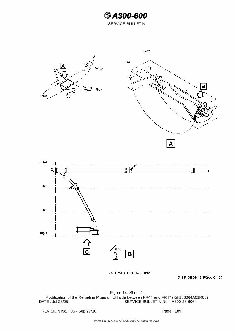
A300-600A300-600SERVICE BULLETIN
Figure 14, Sheet 1Modification of the Refueling Pipes on LH side between FR44 and FR47 (Kit 286064A01R05)
DATE : Jul 28/05 SERVICE BULLETIN No. : A300-28-6064
REVISION No. : 05 - Sep 27/10 Page : 189
Printed in France © AIRBUS 2008 All rights reserved

A300-600A300-600SERVICE BULLETIN
Figure 14, Sheet 2Modification of the Refueling Pipes on LH side between FR44 and FR47 (Kit 286064A01R05)
DATE : Jul 28/05 SERVICE BULLETIN No. : A300-28-6064
REVISION No. : 05 - Sep 27/10 Page : 190
Printed in France © AIRBUS 2008 All rights reserved

A300-600A300-600SERVICE BULLETIN
Figure 14, Sheet 3Modification of the Refueling Pipes on LH side between FR44 and FR47 (Kit 286064A01R05)
DATE : Jul 28/05 SERVICE BULLETIN No. : A300-28-6064
REVISION No. : 05 - Sep 27/10 Page : 191
Printed in France © AIRBUS 2008 All rights reserved

A300-600A300-600SERVICE BULLETIN
Figure 15, Sheet 1Modification of the TTS pipes (Kit 286064A01R05)
DATE : Jul 28/05 SERVICE BULLETIN No. : A300-28-6064
REVISION No. : 05 - Sep 27/10 Page : 192
Printed in France © AIRBUS 2008 All rights reserved

A300-600A300-600SERVICE BULLETIN
Figure 15, Sheet 2Modification of the TTS pipes (Kit 286064A01R05)
DATE : Jul 28/05 SERVICE BULLETIN No. : A300-28-6064
REVISION No. : 05 - Sep 27/10 Page : 193
Printed in France © AIRBUS 2008 All rights reserved

A300-600A300-600SERVICE BULLETIN
Figure 15, Sheet 3Modification of the TTS pipes (Kit 286064A01R05)
DATE : Jul 28/05 SERVICE BULLETIN No. : A300-28-6064
REVISION No. : 05 - Sep 27/10 Page : 194
Printed in France © AIRBUS 2008 All rights reserved
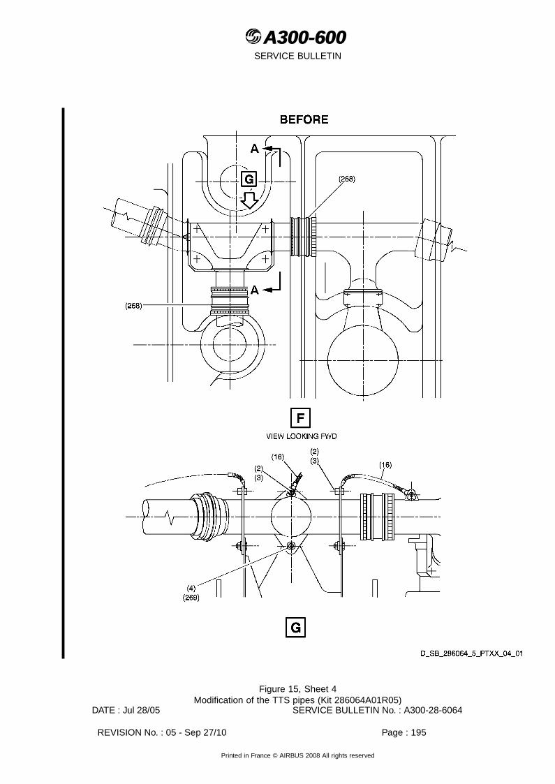
A300-600A300-600SERVICE BULLETIN
Figure 15, Sheet 4Modification of the TTS pipes (Kit 286064A01R05)
DATE : Jul 28/05 SERVICE BULLETIN No. : A300-28-6064
REVISION No. : 05 - Sep 27/10 Page : 195
Printed in France © AIRBUS 2008 All rights reserved

A300-600A300-600SERVICE BULLETIN
Figure 15, Sheet 5Modification of the TTS pipes (Kit 286064A01R05)
DATE : Jul 28/05 SERVICE BULLETIN No. : A300-28-6064
REVISION No. : 05 - Sep 27/10 Page : 196
Printed in France © AIRBUS 2008 All rights reserved

A300-600A300-600SERVICE BULLETIN
Figure 15, Sheet 6Modification of the TTS pipes (Kit 286064A01R05)
DATE : Jul 28/05 SERVICE BULLETIN No. : A300-28-6064
REVISION No. : 05 - Sep 27/10 Page : 197
Printed in France © AIRBUS 2008 All rights reserved

A300-600A300-600SERVICE BULLETIN
Figure 15, Sheet 7Modification of the TTS pipes (Kit 286064A01R05)
DATE : Jul 28/05 SERVICE BULLETIN No. : A300-28-6064
REVISION No. : 05 - Sep 27/10 Page : 198
Printed in France © AIRBUS 2008 All rights reserved

A300-600A300-600SERVICE BULLETIN
Figure 15, Sheet 8Modification of the TTS pipes (Kit 286064A01R05)
DATE : Jul 28/05 SERVICE BULLETIN No. : A300-28-6064
REVISION No. : 05 - Sep 27/10 Page : 199
Printed in France © AIRBUS 2008 All rights reserved

A300-600A300-600SERVICE BULLETIN
Figure 16, Sheet 1Modification of the Feed Pipes (Kit 286064A01R05)
DATE : Jul 28/05 SERVICE BULLETIN No. : A300-28-6064
REVISION No. : 05 - Sep 27/10 Page : 200
Printed in France © AIRBUS 2008 All rights reserved
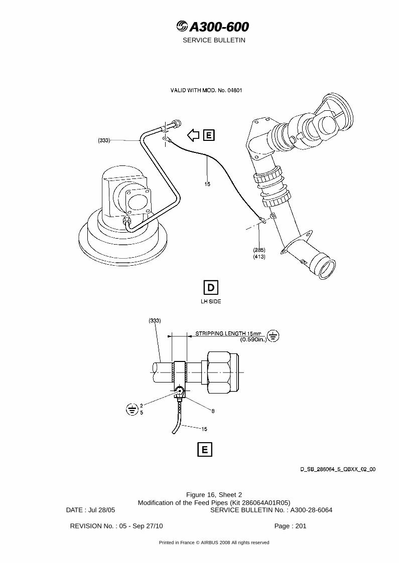
A300-600A300-600SERVICE BULLETIN
Figure 16, Sheet 2Modification of the Feed Pipes (Kit 286064A01R05)
DATE : Jul 28/05 SERVICE BULLETIN No. : A300-28-6064
REVISION No. : 05 - Sep 27/10 Page : 201
Printed in France © AIRBUS 2008 All rights reserved

A300-600A300-600SERVICE BULLETIN
Figure 16, Sheet 3Modification of the Feed Pipes (Kit 286064A01R05)
DATE : Jul 28/05 SERVICE BULLETIN No. : A300-28-6064
REVISION No. : 05 - Sep 27/10 Page : 202
Printed in France © AIRBUS 2008 All rights reserved
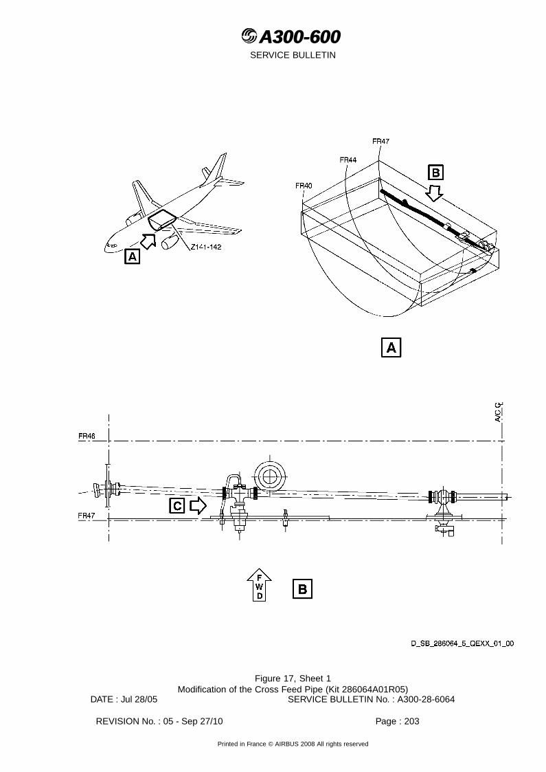
A300-600A300-600SERVICE BULLETIN
Figure 17, Sheet 1Modification of the Cross Feed Pipe (Kit 286064A01R05)
DATE : Jul 28/05 SERVICE BULLETIN No. : A300-28-6064
REVISION No. : 05 - Sep 27/10 Page : 203
Printed in France © AIRBUS 2008 All rights reserved

A300-600A300-600SERVICE BULLETIN
Figure 17, Sheet 2Modification of the Cross Feed Pipe (Kit 286064A01R05)
DATE : Jul 28/05 SERVICE BULLETIN No. : A300-28-6064
REVISION No. : 05 - Sep 27/10 Page : 204
Printed in France © AIRBUS 2008 All rights reserved

A300-600A300-600SERVICE BULLETIN
Figure 18, Sheet 1Modification of the Refueling Pipes on LH side between FR44 and FR47 (Kit 286064A02R02)
DATE : Jul 28/05 SERVICE BULLETIN No. : A300-28-6064
REVISION No. : 05 - Sep 27/10 Page : 205
Printed in France © AIRBUS 2008 All rights reserved

A300-600A300-600SERVICE BULLETIN
Figure 18, Sheet 2Modification of the Refueling Pipes on LH side between FR44 and FR47 (Kit 286064A02R02)
DATE : Jul 28/05 SERVICE BULLETIN No. : A300-28-6064
REVISION No. : 05 - Sep 27/10 Page : 206
Printed in France © AIRBUS 2008 All rights reserved

A300-600A300-600SERVICE BULLETIN
Figure 18, Sheet 3Modification of the Refueling Pipes on LH side between FR44 and FR47 (Kit 286064A02R02)
DATE : Jul 28/05 SERVICE BULLETIN No. : A300-28-6064
REVISION No. : 05 - Sep 27/10 Page : 207
Printed in France © AIRBUS 2008 All rights reserved

A300-600A300-600SERVICE BULLETIN
Figure 19, Sheet 1Modification of the TTS pipes (Kit 286064A02R02)
DATE : Jul 28/05 SERVICE BULLETIN No. : A300-28-6064
REVISION No. : 05 - Sep 27/10 Page : 208
Printed in France © AIRBUS 2008 All rights reserved

A300-600A300-600SERVICE BULLETIN
Figure 19, Sheet 2Modification of the TTS pipes (Kit 286064A02R02)
DATE : Jul 28/05 SERVICE BULLETIN No. : A300-28-6064
REVISION No. : 05 - Sep 27/10 Page : 209
Printed in France © AIRBUS 2008 All rights reserved

A300-600A300-600SERVICE BULLETIN
Figure 19, Sheet 3Modification of the TTS pipes (Kit 286064A02R02)
DATE : Jul 28/05 SERVICE BULLETIN No. : A300-28-6064
REVISION No. : 05 - Sep 27/10 Page : 210
Printed in France © AIRBUS 2008 All rights reserved

A300-600A300-600SERVICE BULLETIN
Figure 19, Sheet 4Modification of the TTS pipes (Kit 286064A02R02)
DATE : Jul 28/05 SERVICE BULLETIN No. : A300-28-6064
REVISION No. : 05 - Sep 27/10 Page : 211
Printed in France © AIRBUS 2008 All rights reserved

A300-600A300-600SERVICE BULLETIN
Figure 19, Sheet 5Modification of the TTS pipes (Kit 286064A02R02)
DATE : Jul 28/05 SERVICE BULLETIN No. : A300-28-6064
REVISION No. : 05 - Sep 27/10 Page : 212
Printed in France © AIRBUS 2008 All rights reserved

A300-600A300-600SERVICE BULLETIN
Figure 19, Sheet 6Modification of the TTS pipes (Kit 286064A02R02)
DATE : Jul 28/05 SERVICE BULLETIN No. : A300-28-6064
REVISION No. : 05 - Sep 27/10 Page : 213
Printed in France © AIRBUS 2008 All rights reserved

A300-600A300-600SERVICE BULLETIN
Figure 19, Sheet 7Modification of the TTS pipes (Kit 286064A02R02)
DATE : Jul 28/05 SERVICE BULLETIN No. : A300-28-6064
REVISION No. : 05 - Sep 27/10 Page : 214
Printed in France © AIRBUS 2008 All rights reserved

A300-600A300-600SERVICE BULLETIN
Figure 19, Sheet 8Modification of the TTS pipes (Kit 286064A02R02)
DATE : Jul 28/05 SERVICE BULLETIN No. : A300-28-6064
REVISION No. : 05 - Sep 27/10 Page : 215
Printed in France © AIRBUS 2008 All rights reserved
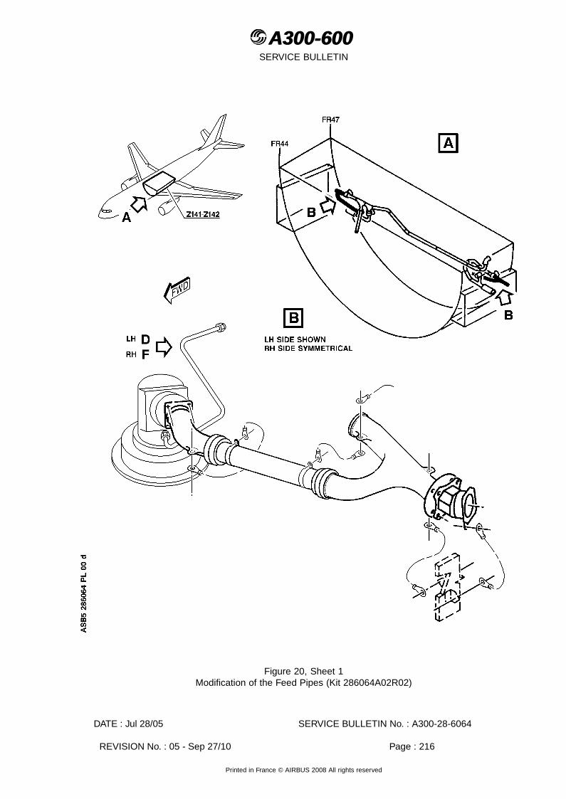
A300-600A300-600SERVICE BULLETIN
Figure 20, Sheet 1Modification of the Feed Pipes (Kit 286064A02R02)
DATE : Jul 28/05 SERVICE BULLETIN No. : A300-28-6064
REVISION No. : 05 - Sep 27/10 Page : 216
Printed in France © AIRBUS 2008 All rights reserved

A300-600A300-600SERVICE BULLETIN
Figure 20, Sheet 2Modification of the Feed Pipes (Kit 286064A02R02)
DATE : Jul 28/05 SERVICE BULLETIN No. : A300-28-6064
REVISION No. : 05 - Sep 27/10 Page : 217
Printed in France © AIRBUS 2008 All rights reserved

A300-600A300-600SERVICE BULLETIN
Figure 20, Sheet 3Modification of the Feed Pipes (Kit 286064A02R02)
DATE : Jul 28/05 SERVICE BULLETIN No. : A300-28-6064
REVISION No. : 05 - Sep 27/10 Page : 218
Printed in France © AIRBUS 2008 All rights reserved

A300-600A300-600SERVICE BULLETIN
Figure 21, Sheet 1Modification of the Cross Feed Pipe (Kit 286064A02R02)
DATE : Jul 28/05 SERVICE BULLETIN No. : A300-28-6064
REVISION No. : 05 - Sep 27/10 Page : 219
Printed in France © AIRBUS 2008 All rights reserved

A300-600A300-600SERVICE BULLETIN
Figure 21, Sheet 2Modification of the Cross Feed Pipe (Kit 286064A02R02)
DATE : Jul 28/05 SERVICE BULLETIN No. : A300-28-6064
REVISION No. : 05 - Sep 27/10 Page : 220
Printed in France © AIRBUS 2008 All rights reserved

A300-600A300-600SERVICE BULLETIN
Figure 22, Sheet 1Electrical Bonding of the Canister Pumps (Kit 286064A03R00)
DATE : Jul 28/05 SERVICE BULLETIN No. : A300-28-6064
REVISION No. : 05 - Sep 27/10 Page : 221
Printed in France © AIRBUS 2008 All rights reserved
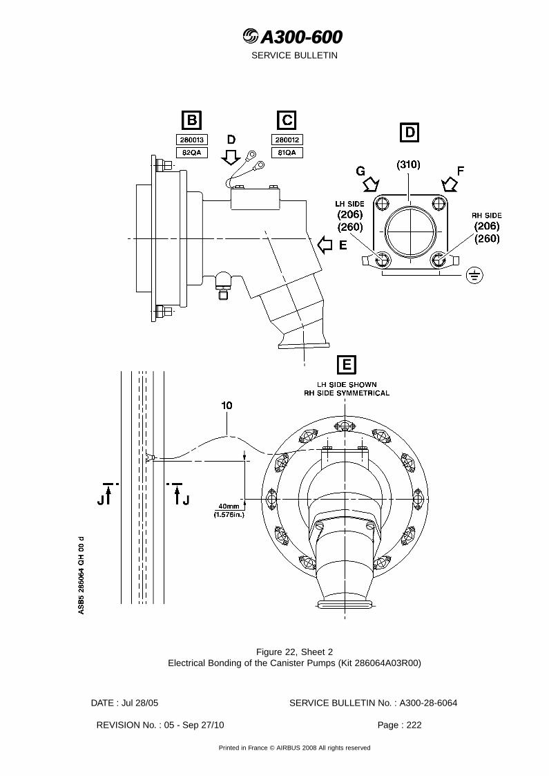
A300-600A300-600SERVICE BULLETIN
Figure 22, Sheet 2Electrical Bonding of the Canister Pumps (Kit 286064A03R00)
DATE : Jul 28/05 SERVICE BULLETIN No. : A300-28-6064
REVISION No. : 05 - Sep 27/10 Page : 222
Printed in France © AIRBUS 2008 All rights reserved

A300-600A300-600SERVICE BULLETIN
Figure 22, Sheet 3Electrical Bonding of the Canister Pumps (Kit 286064A03R00)
DATE : Jul 28/05 SERVICE BULLETIN No. : A300-28-6064
REVISION No. : 05 - Sep 27/10 Page : 223
Printed in France © AIRBUS 2008 All rights reserved

A300-600A300-600SERVICE BULLETIN
Figure 23, Sheet 1Water Drains and Water Drain Valves Electrical Bonding
DATE : Jul 28/05 SERVICE BULLETIN No. : A300-28-6064
REVISION No. : 05 - Sep 27/10 Page : 224
Printed in France © AIRBUS 2008 All rights reserved

A300-600A300-600SERVICE BULLETIN
Figure 23, Sheet 2Water Drains and Water Drain Valves Electrical Bonding
DATE : Jul 28/05 SERVICE BULLETIN No. : A300-28-6064
REVISION No. : 05 - Sep 27/10 Page : 225
Printed in France © AIRBUS 2008 All rights reserved
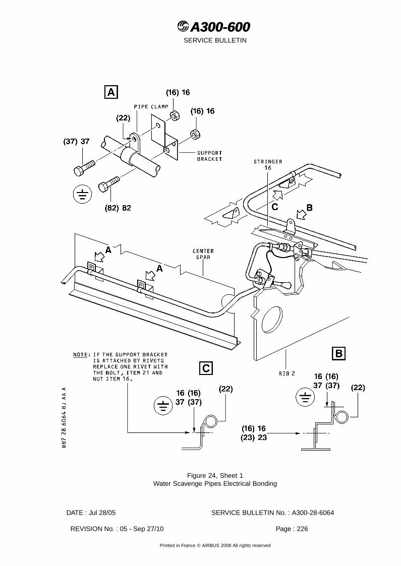
A300-600A300-600SERVICE BULLETIN
Figure 24, Sheet 1Water Scavenge Pipes Electrical Bonding
DATE : Jul 28/05 SERVICE BULLETIN No. : A300-28-6064
REVISION No. : 05 - Sep 27/10 Page : 226
Printed in France © AIRBUS 2008 All rights reserved

A300-600A300-600SERVICE BULLETIN
Figure 24, Sheet 2Water Scavenge Pipes Electrical Bonding
DATE : Jul 28/05 SERVICE BULLETIN No. : A300-28-6064
REVISION No. : 05 - Sep 27/10 Page : 227
Printed in France © AIRBUS 2008 All rights reserved

A300-600A300-600SERVICE BULLETIN
Figure 25, Sheet 1Magnetic Level Indicators Electrical Bonding
DATE : Jul 28/05 SERVICE BULLETIN No. : A300-28-6064
REVISION No. : 05 - Sep 27/10 Page : 228
Printed in France © AIRBUS 2008 All rights reserved
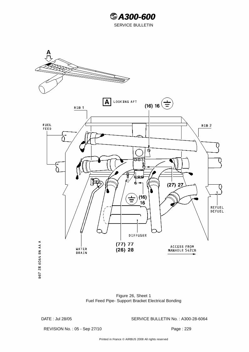
A300-600A300-600SERVICE BULLETIN
Figure 26, Sheet 1Fuel Feed Pipe- Support Bracket Electrical Bonding
DATE : Jul 28/05 SERVICE BULLETIN No. : A300-28-6064
REVISION No. : 05 - Sep 27/10 Page : 229
Printed in France © AIRBUS 2008 All rights reserved
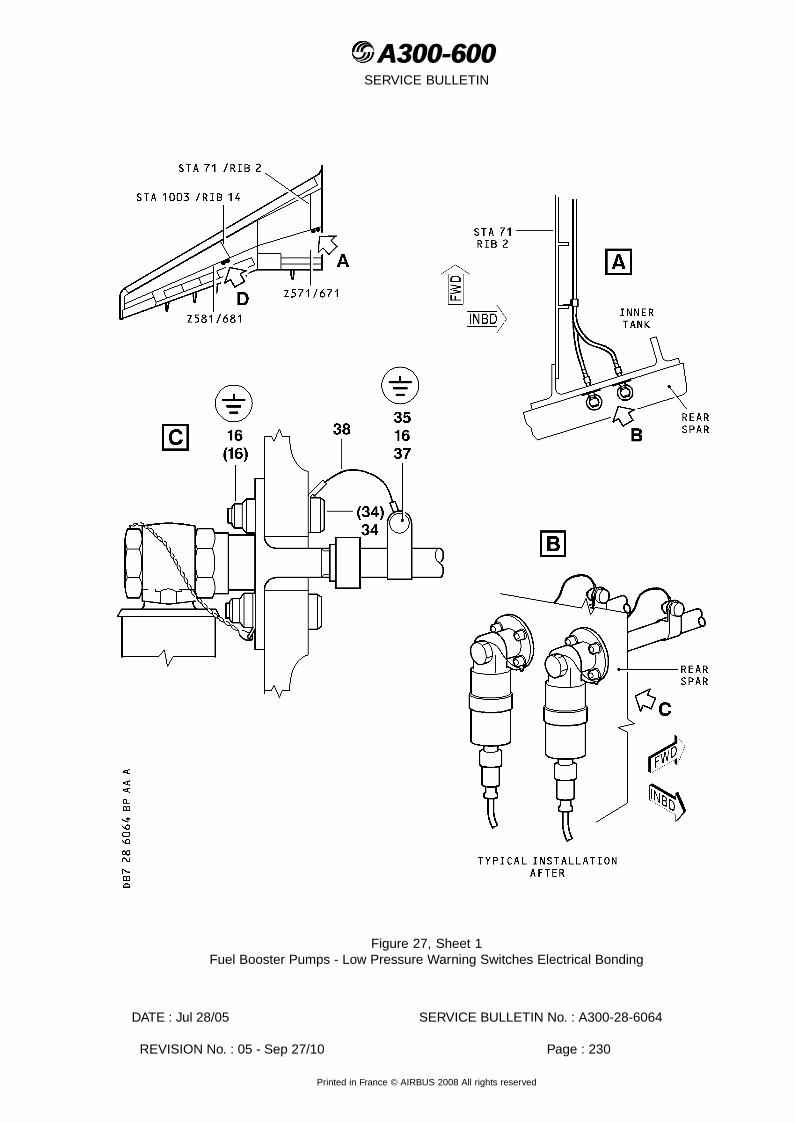
A300-600A300-600SERVICE BULLETIN
Figure 27, Sheet 1Fuel Booster Pumps - Low Pressure Warning Switches Electrical Bonding
DATE : Jul 28/05 SERVICE BULLETIN No. : A300-28-6064
REVISION No. : 05 - Sep 27/10 Page : 230
Printed in France © AIRBUS 2008 All rights reserved

A300-600A300-600SERVICE BULLETIN
Figure 27, Sheet 2Fuel Booster Pumps - Low Pressure Warning Switches Electrical Bonding
DATE : Jul 28/05 SERVICE BULLETIN No. : A300-28-6064
REVISION No. : 05 - Sep 27/10 Page : 231
Printed in France © AIRBUS 2008 All rights reserved
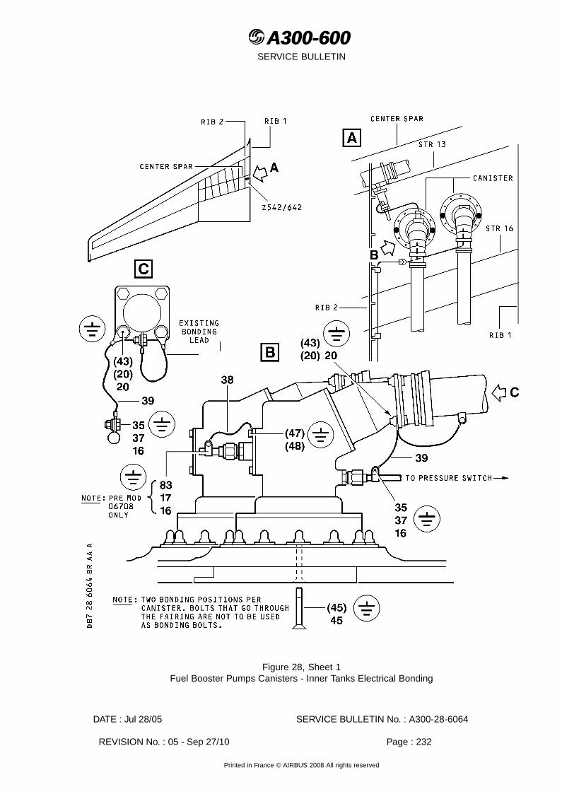
A300-600A300-600SERVICE BULLETIN
Figure 28, Sheet 1Fuel Booster Pumps Canisters - Inner Tanks Electrical Bonding
DATE : Jul 28/05 SERVICE BULLETIN No. : A300-28-6064
REVISION No. : 05 - Sep 27/10 Page : 232
Printed in France © AIRBUS 2008 All rights reserved

A300-600A300-600SERVICE BULLETIN
Figure 29, Sheet 1Fuel Diffusers - Inner and Outer Tanks Electrical Bonding
DATE : Jul 28/05 SERVICE BULLETIN No. : A300-28-6064
REVISION No. : 05 - Sep 27/10 Page : 233
Printed in France © AIRBUS 2008 All rights reserved

A300-600A300-600SERVICE BULLETIN
Figure 29, Sheet 2Fuel Diffusers - Inner and Outer Tanks Electrical Bonding
DATE : Jul 28/05 SERVICE BULLETIN No. : A300-28-6064
REVISION No. : 05 - Sep 27/10 Page : 234
Printed in France © AIRBUS 2008 All rights reserved

A300-600A300-600SERVICE BULLETIN
Figure 29, Sheet 3Fuel Diffusers - Inner and Outer Tanks Electrical Bonding
DATE : Jul 28/05 SERVICE BULLETIN No. : A300-28-6064
REVISION No. : 05 - Sep 27/10 Page : 235
Printed in France © AIRBUS 2008 All rights reserved
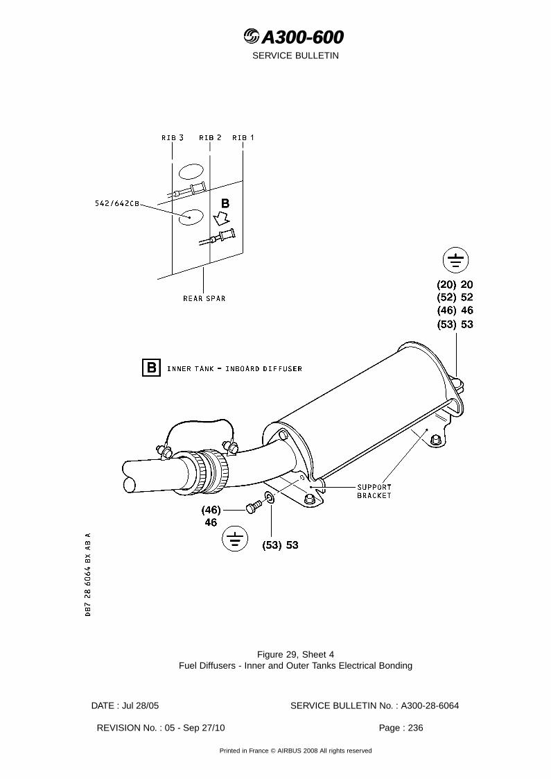
A300-600A300-600SERVICE BULLETIN
Figure 29, Sheet 4Fuel Diffusers - Inner and Outer Tanks Electrical Bonding
DATE : Jul 28/05 SERVICE BULLETIN No. : A300-28-6064
REVISION No. : 05 - Sep 27/10 Page : 236
Printed in France © AIRBUS 2008 All rights reserved

A300-600A300-600SERVICE BULLETIN
Figure 30, Sheet 1Wings - Fuel Level Sensors Electrical Bonding
DATE : Jul 28/05 SERVICE BULLETIN No. : A300-28-6064
REVISION No. : 05 - Sep 27/10 Page : 237
Printed in France © AIRBUS 2008 All rights reserved

A300-600A300-600SERVICE BULLETIN
Figure 30, Sheet 2Wings - Fuel Level Sensors Electrical Bonding
DATE : Jul 28/05 SERVICE BULLETIN No. : A300-28-6064
REVISION No. : 05 - Sep 27/10 Page : 238
Printed in France © AIRBUS 2008 All rights reserved

A300-600A300-600SERVICE BULLETIN
Figure 30, Sheet 3Wings - Fuel Level Sensors Electrical Bonding
DATE : Jul 28/05 SERVICE BULLETIN No. : A300-28-6064
REVISION No. : 05 - Sep 27/10 Page : 239
Printed in France © AIRBUS 2008 All rights reserved
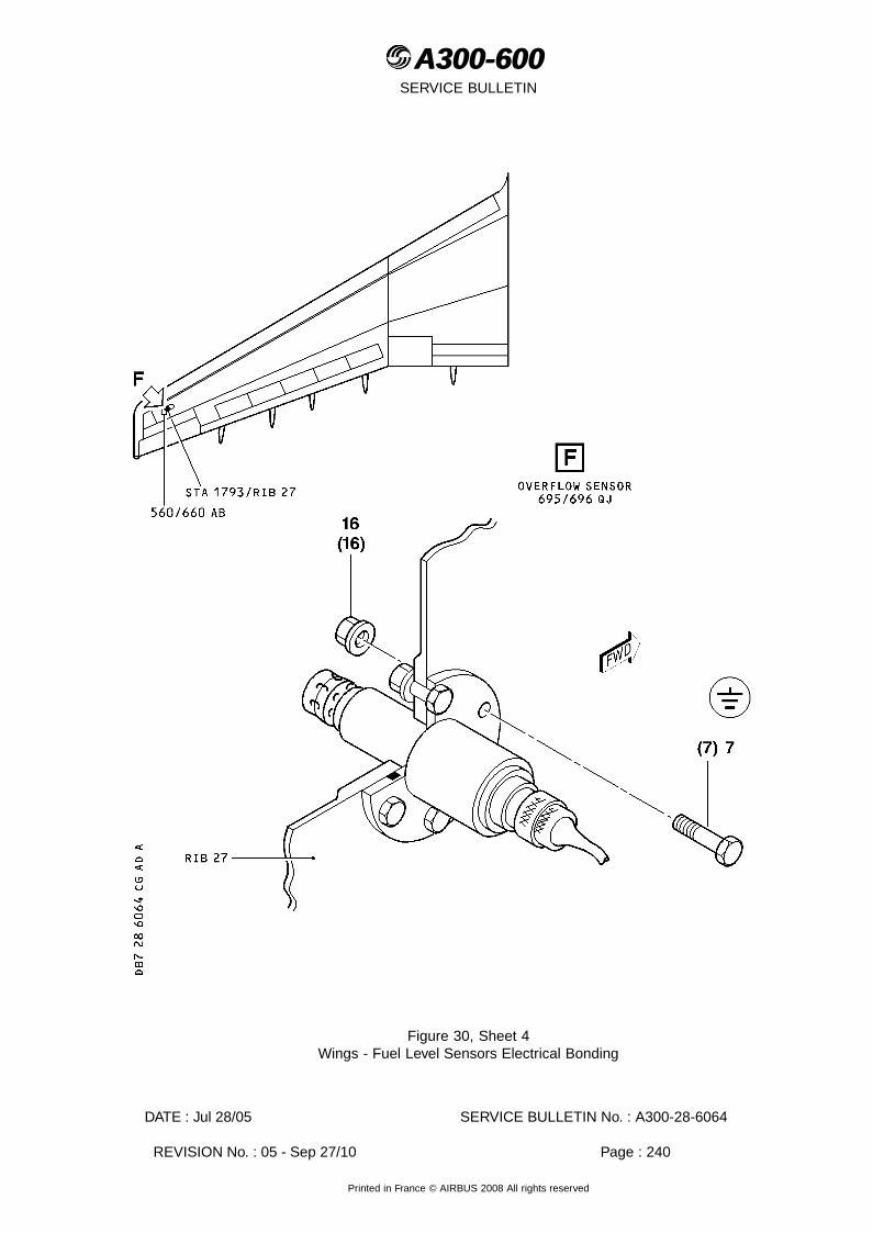
A300-600A300-600SERVICE BULLETIN
Figure 30, Sheet 4Wings - Fuel Level Sensors Electrical Bonding
DATE : Jul 28/05 SERVICE BULLETIN No. : A300-28-6064
REVISION No. : 05 - Sep 27/10 Page : 240
Printed in France © AIRBUS 2008 All rights reserved

A300-600A300-600SERVICE BULLETIN
Figure 31, Sheet 1Slat Track Canister 3 and Typical Canister Drain Attachment Electrical Bonding
DATE : Jul 28/05 SERVICE BULLETIN No. : A300-28-6064
REVISION No. : 05 - Sep 27/10 Page : 241
Printed in France © AIRBUS 2008 All rights reserved

A300-600A300-600SERVICE BULLETIN
Figure 31, Sheet 2Slat Track Canister 3 and Typical Canister Drain Attachment Electrical Bonding
DATE : Jul 28/05 SERVICE BULLETIN No. : A300-28-6064
REVISION No. : 05 - Sep 27/10 Page : 242
Printed in France © AIRBUS 2008 All rights reserved

A300-600A300-600SERVICE BULLETIN
Figure 32, Sheet 1Slat Track Canister 4 Electrical Bonding
DATE : Jul 28/05 SERVICE BULLETIN No. : A300-28-6064
REVISION No. : 05 - Sep 27/10 Page : 243
Printed in France © AIRBUS 2008 All rights reserved

A300-600A300-600SERVICE BULLETIN
Figure 33, Sheet 1Screwjack Canister 3 and Typical Canister Drain Attachment Electrical Bonding
DATE : Jul 28/05 SERVICE BULLETIN No. : A300-28-6064
REVISION No. : 05 - Sep 27/10 Page : 244
Printed in France © AIRBUS 2008 All rights reserved

A300-600A300-600SERVICE BULLETIN
Figure 33, Sheet 2Screwjack Canister 3 and Typical Canister Drain Attachment Electrical Bonding
DATE : Jul 28/05 SERVICE BULLETIN No. : A300-28-6064
REVISION No. : 05 - Sep 27/10 Page : 245
Printed in France © AIRBUS 2008 All rights reserved
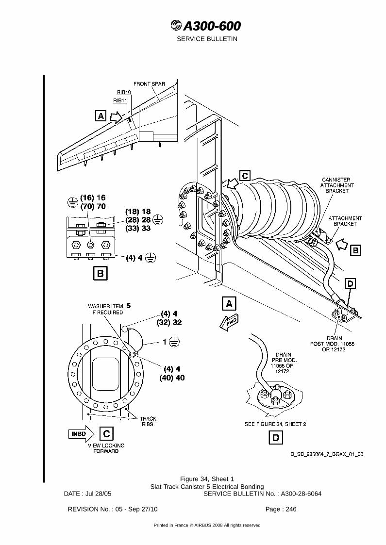
A300-600A300-600SERVICE BULLETIN
Figure 34, Sheet 1Slat Track Canister 5 Electrical Bonding
DATE : Jul 28/05 SERVICE BULLETIN No. : A300-28-6064
REVISION No. : 05 - Sep 27/10 Page : 246
Printed in France © AIRBUS 2008 All rights reserved

A300-600A300-600SERVICE BULLETIN
Figure 35, Sheet 1Cadensicon (RH Wing only) Electrical Bonding
DATE : Jul 28/05 SERVICE BULLETIN No. : A300-28-6064
REVISION No. : 05 - Sep 27/10 Page : 247
Printed in France © AIRBUS 2008 All rights reserved
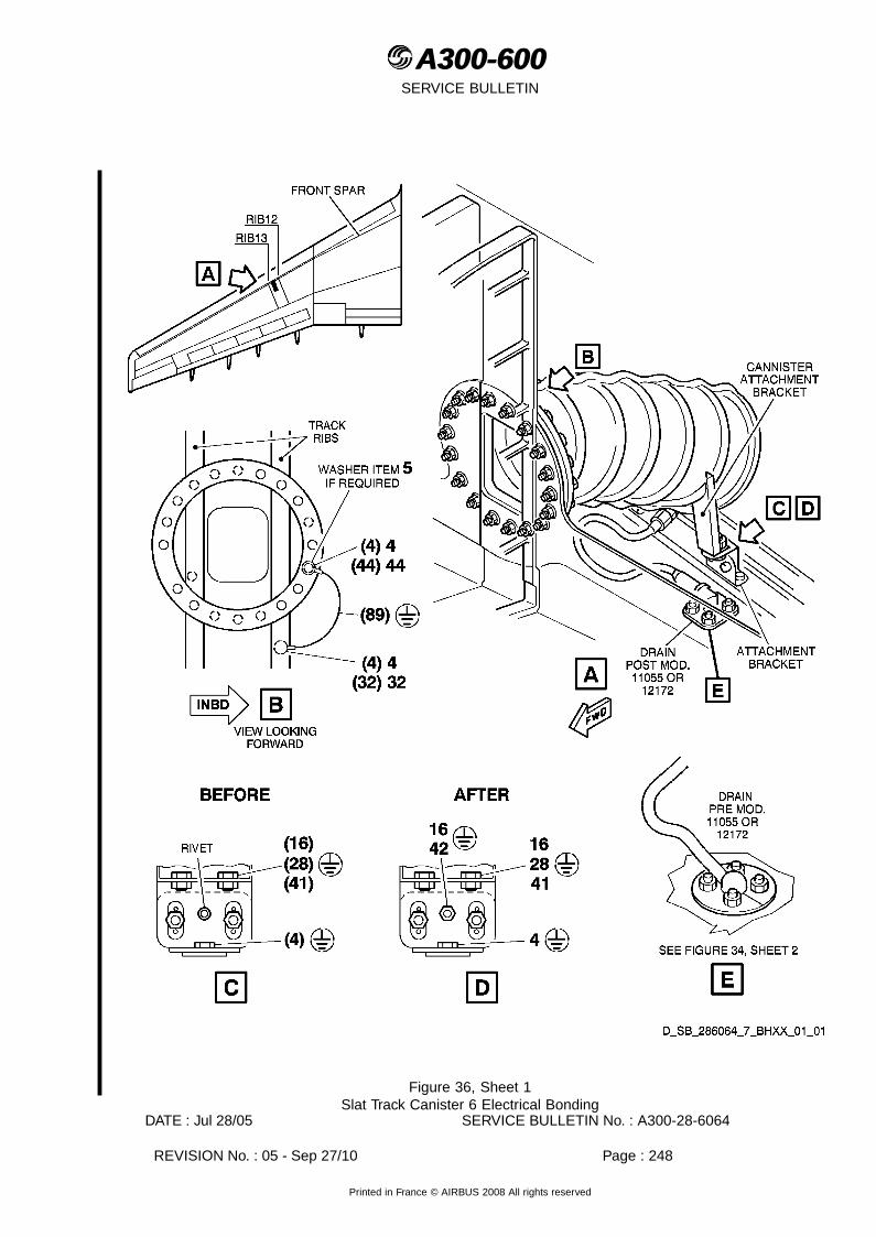
A300-600A300-600SERVICE BULLETIN
Figure 36, Sheet 1Slat Track Canister 6 Electrical Bonding
DATE : Jul 28/05 SERVICE BULLETIN No. : A300-28-6064
REVISION No. : 05 - Sep 27/10 Page : 248
Printed in France © AIRBUS 2008 All rights reserved

A300-600A300-600SERVICE BULLETIN
Figure 37, Sheet 1Refuel/Defuel Valves Electrical Bonding
DATE : Jul 28/05 SERVICE BULLETIN No. : A300-28-6064
REVISION No. : 05 - Sep 27/10 Page : 249
Printed in France © AIRBUS 2008 All rights reserved
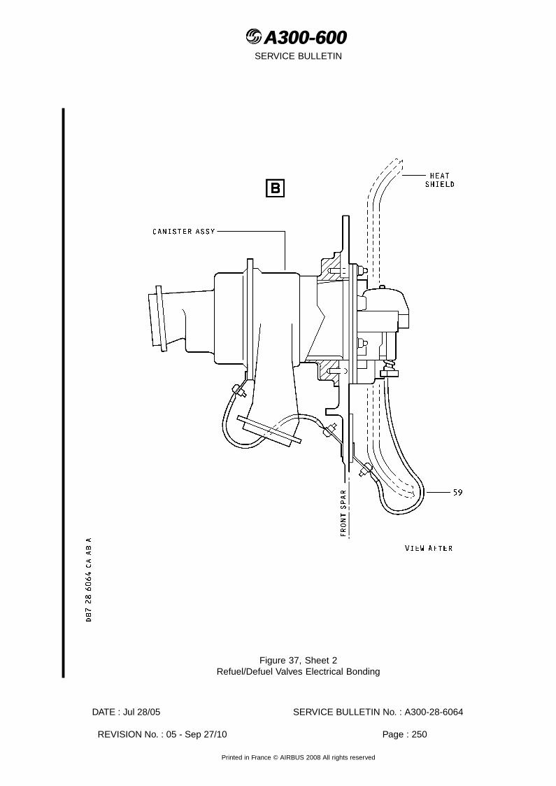
A300-600A300-600SERVICE BULLETIN
Figure 37, Sheet 2Refuel/Defuel Valves Electrical Bonding
DATE : Jul 28/05 SERVICE BULLETIN No. : A300-28-6064
REVISION No. : 05 - Sep 27/10 Page : 250
Printed in France © AIRBUS 2008 All rights reserved

A300-600A300-600SERVICE BULLETIN
Figure 38, Sheet 1Provision for a Fuel Jettison System - Blanking Plates Electrical Bonding
DATE : Jul 28/05 SERVICE BULLETIN No. : A300-28-6064
REVISION No. : 05 - Sep 27/10 Page : 251
Printed in France © AIRBUS 2008 All rights reserved
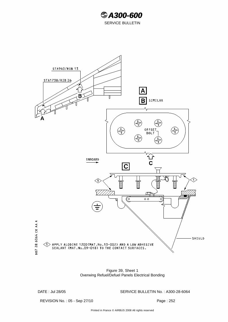
A300-600A300-600SERVICE BULLETIN
Figure 39, Sheet 1Overwing Refuel/Defuel Panels Electrical Bonding
DATE : Jul 28/05 SERVICE BULLETIN No. : A300-28-6064
REVISION No. : 05 - Sep 27/10 Page : 252
Printed in France © AIRBUS 2008 All rights reserved

A300-600A300-600SERVICE BULLETIN
Figure 40, Sheet 1Screwjack Canister 4 Electrical Bonding
DATE : Jul 28/05 SERVICE BULLETIN No. : A300-28-6064
REVISION No. : 05 - Sep 27/10 Page : 253
Printed in France © AIRBUS 2008 All rights reserved

A300-600A300-600SERVICE BULLETIN
Figure 41, Sheet 1Fuel Booster Pumps Canisters - Outer Tanks Electrical Bonding
DATE : Jul 28/05 SERVICE BULLETIN No. : A300-28-6064
REVISION No. : 05 - Sep 27/10 Page : 254
Printed in France © AIRBUS 2008 All rights reserved

A300-600A300-600SERVICE BULLETIN
Figure 42, Sheet 1Slat Track Canister 7 Electrical Bonding
DATE : Jul 28/05 SERVICE BULLETIN No. : A300-28-6064
REVISION No. : 05 - Sep 27/10 Page : 255
Printed in France © AIRBUS 2008 All rights reserved

A300-600A300-600SERVICE BULLETIN
Figure 43, Sheet 1Slat Track Canister 8 Electrical Bonding
DATE : Jul 28/05 SERVICE BULLETIN No. : A300-28-6064
REVISION No. : 05 - Sep 27/10 Page : 256
Printed in France © AIRBUS 2008 All rights reserved

A300-600A300-600SERVICE BULLETIN
Figure 44, Sheet 1Screwjack Canister 5 Electrical Bonding
DATE : Jul 28/05 SERVICE BULLETIN No. : A300-28-6064
REVISION No. : 05 - Sep 27/10 Page : 257
Printed in France © AIRBUS 2008 All rights reserved

A300-600A300-600SERVICE BULLETIN
Figure 45, Sheet 1Slat Track Canister 9 Electrical Bonding
DATE : Jul 28/05 SERVICE BULLETIN No. : A300-28-6064
REVISION No. : 05 - Sep 27/10 Page : 258
Printed in France © AIRBUS 2008 All rights reserved
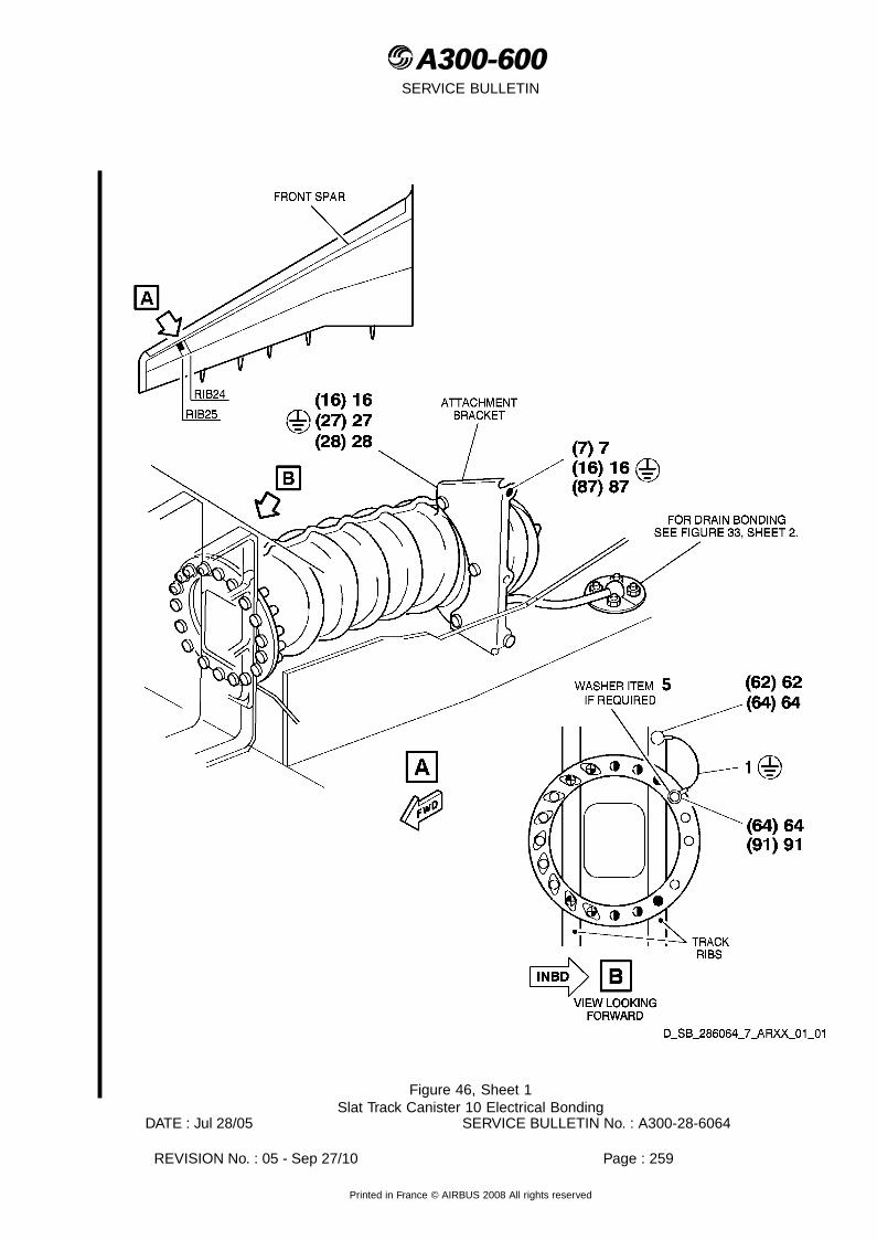
A300-600A300-600SERVICE BULLETIN
Figure 46, Sheet 1Slat Track Canister 10 Electrical Bonding
DATE : Jul 28/05 SERVICE BULLETIN No. : A300-28-6064
REVISION No. : 05 - Sep 27/10 Page : 259
Printed in France © AIRBUS 2008 All rights reserved

A300-600A300-600SERVICE BULLETIN
Figure 47, Sheet 1Screwjack Canister 6 Electrical Bonding
DATE : Jul 28/05 SERVICE BULLETIN No. : A300-28-6064
REVISION No. : 05 - Sep 27/10 Page : 260
Printed in France © AIRBUS 2008 All rights reserved

A300-600A300-600SERVICE BULLETIN
Figure 47, Sheet 2Screwjack Canister 6 Electrical Bonding
DATE : Jul 28/05 SERVICE BULLETIN No. : A300-28-6064
REVISION No. : 05 - Sep 27/10 Page : 261
Printed in France © AIRBUS 2008 All rights reserved

A300-600A300-600SERVICE BULLETIN
Figure 48, Sheet 1Slat Track Canister 11 Electrical Bonding
DATE : Jul 28/05 SERVICE BULLETIN No. : A300-28-6064
REVISION No. : 05 - Sep 27/10 Page : 262
Printed in France © AIRBUS 2008 All rights reserved

A300-600A300-600SERVICE BULLETIN
Figure 49, Sheet 1Overpressure Protector Electrical Bonding
DATE : Jul 28/05 SERVICE BULLETIN No. : A300-28-6064
REVISION No. : 05 - Sep 27/10 Page : 263
Printed in France © AIRBUS 2008 All rights reserved
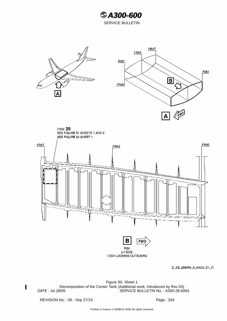
A300-600A300-600SERVICE BULLETIN
Figure 50, Sheet 1Decomposition of the Center Tank (Additional work, Introduced by Rev 03)
DATE : Jul 28/05 SERVICE BULLETIN No. : A300-28-6064
REVISION No. : 05 - Sep 27/10 Page : 264
Printed in France © AIRBUS 2008 All rights reserved

A300-600A300-600SERVICE BULLETIN
Figure 51, Sheet 1Location of the Bonding Points on the Rib 1 (LH side) (Additional work, Introduced by Rev 03)
DATE : Jul 28/05 SERVICE BULLETIN No. : A300-28-6064
REVISION No. : 05 - Sep 27/10 Page : 265
Printed in France © AIRBUS 2008 All rights reserved

A300-600A300-600SERVICE BULLETIN
Figure 51, Sheet 2Location of the Bonding Points on the Rib 1 (LH side) (Additional work, Introduced by Rev 03)
DATE : Jul 28/05 SERVICE BULLETIN No. : A300-28-6064
REVISION No. : 05 - Sep 27/10 Page : 266
Printed in France © AIRBUS 2008 All rights reserved

A300-600A300-600SERVICE BULLETIN
Figure 52, Sheet 1Bonding Points to check on the Rib 1 (LH side) (Additional work, Introduced by Rev 03)
DATE : Jul 28/05 SERVICE BULLETIN No. : A300-28-6064
REVISION No. : 05 - Sep 27/10 Page : 267
Printed in France © AIRBUS 2008 All rights reserved

A300-600A300-600SERVICE BULLETIN
This Page Intentionally Left Blank
DATE : Jul 28/05 SERVICE BULLETIN No. : A300-28-6064
REVISION No. : 05 - Sep 27/10 Page : 268
Printed in France © AIRBUS 2008 All rights reserved

A300-600A300-600SERVICE BULLETINREPORTING SHEET
TITLE : FUEL - GENERAL - MODIFY THE EQUIPMENT IN THE FUEL TANKS FOR ADDITIONALELECTRICAL BONDING
MODIFICATION No. : 12495H5555
Please complete the appropriate item (A or B):
A - SB WILL BE embodied .................................................................. YES/NO (if NO please comment)If YES, aircraft concerned (as per SB effectivity by default) and planned dates (month/year) of embodiement:..........................................................................................................................................................................................................................................................................................................................................................
B - SB HAS BEEN embodied on aircraft: ......................................................................................................................................................................................................................................................................................................................................................................................................................................................................
Operator comments:......................................................................................................................................................................................................................................................................................................................................................................................................................................................................................................
From Airline: ........................................................................................................................................................Name/Title: ..........................................................................................................................................................Signature:..................... Date: .....................................................
If operational documentation is affected (see Paragraph 1.K of this SB): If information is needed prior to nextnormal revision or prior to SB embodiment, please indicate required service(s):Either : Advance data................................................................................... YES/NOOr : Intermediate/Temporary revision ..................................................... YES/NO
Important Information: This SB will only be incorporated in your maintenance and operational documentationif this sheet is returned to Airbus and signed by a duly authorised representative. With the next feasiblerevision, this will result in
- updating of maintenance documentation to show pre and post SB data.- updating of maintenance and operational documentation to show post SB dataafter embodiment.
If this SB requires previous or simultaneous accomplishment of other SBs, Airbus shall automatically includethem in the manual revisions. Refer to SIL 00-037 for detailed information.
Please return this completed sheet to:
AIRBUSCUSTOMER SERVICES DIRECTORATE1 Rond Point Maurice Bellonte31707 BLAGNAC CEDEX FRANCE
Attn: SEDCC1 Technical Data and Documentation ServicesFAX: (+33) 5 61 93 28 06e-mail: [email protected] via your Resident Customer Support Office.
Alternatively, SB lists via letters or fax are also accepted.
DATE : Jul 28/05 SERVICE BULLETIN No. : A300-28-6064
REVISION No. : 05 - Sep 27/10 Page : 1 of 1
Printed in France © AIRBUS 2008 All rights reserved

A300-600A300-600SERVICE BULLETIN
REPORTING QUALITY
TITLE : FUEL - GENERAL - MODIFY THE EQUIPMENT IN THE FUEL TANKS FOR ADDITIONALELECTRICAL BONDING
MODIFICATION No. : 12495H5555
Use this form to tell us what is your perception of the quality of this Service Bulletin.The reported data that youprovide us will be used to analyse areas of difficulties and to take corrective action to futher improve the qualityof our Service Bulletins.We thank you for the time you have taken in completing this form.
(Please rate on a scale of 1 to 4, with 4 being the highest score)
-Quality rating of this SB 4 3 2 1
-Quality rating of the Accomplishment Instructions 4 3 2 1
-Quality rating of the Illustrations 4 3 2 1
-Is this SB easy to understand ? Y / N
If you have had difficulties in the accomplishment of this SB please quote below the area(s) and give a shortdescription of the issue.
Planning Material InstructionsX Effectivity X Kit Content X PreparationX Reason X List of Materials X Mod/InspectionX Manpower Operator Supplied X TestX References X Re-identification X Close-upX Publication X Tooling X Illustrations
Comments :
Operator : Date:
Name/Title :
Please return this form to:
AIRBUSCUSTOMER SERVICES DIRECTORATE1 Rond Point Maurice Bellonte31707 BLAGNAC CEDEX FRANCE
Attn: SEMB Service Bulletins ManagementFAX: (+33) 5 61 93 42 51Or via your Resident Customer Support Office.
DATE : Jul 28/05 SERVICE BULLETIN No. : A300-28-6064
REVISION No. : 05 - Sep 27/10 Page : 1 of 1
Printed in France © AIRBUS 2008 All rights reserved