Embed Size (px)
Citation preview
J. R. Soc. Interface (2012) 9, 2424–2436
on July 6, 2018http://rsif.royalsocietypublishing.org/Downloaded from
*Author for c
doi:10.1098/rsif.2012.0200Published online 9 May 2012
Received 13 MAccepted 18 A
Design of gecko-inspired fibrillarsurfaces with strong attachment andeasy-removal properties: a numerical
analysis of peel-zoneMing Zhou1, Noshir Pesika2, Hongbo Zeng3, Jin Wan1,
Xiangjun Zhang1, Yonggang Meng1, Shizhu Wen1 and Yu Tian1,*1State Key Laboratory of Tribology, Tsinghua University, Beijing 100084,
People’s Republic of China2Chemical and Biomolecular Engineering Department, Tulane University,
New Orleans, LA 70118, USA3Chemical and Materials Engineering Department, University of Alberta,
Edmonton, Alberta, Canada T6G 2V4
Despite successful fabrication of gecko-inspired fibrillar surfaces with strong adhesion forces,how to achieve an easy-removal property becomes a major concern that may restrict the wideapplications of these bio-inspired surfaces. Research on how geckos detach rapidly has inspiredthe design of novel adhesive surfaces with strong and reversible adhesion capabilities, whichrelies on further fundamental understanding of the peeling mechanisms. Recent studiesshowed that the peel-zone plays an important role in the peeling off of adhesive tapes or fibrillarsurfaces. In this study, a numerical method was developed to evaluate peel-zone deformationand the resulting mechanical behaviour due to the deformations of fibrillar surfaces detachingfrom a smooth rigid substrate. The effect of the geometrical parameters of pillars and the stiff-ness of backing layer on the peel-zone and peel strength, and the strong attachment and easy-removal properties have been analysed to establish a design map for bio-inspired fibrillar sur-faces, which shows that the optimized strong attachment and easy-removal properties canvary by over three orders of magnitude. The adhesion and peeling design map established pro-vides new insights into the design and development of novel gecko-inspired fibrillar surfaces.
Keywords: gecko-inspired surface; peel zone; easy removal; adhesion andpeeling design map
1. INTRODUCTION
Interfacial science and engineering has been widelystudied to achieve various functionalities based on thematerial chemistry and micro/nano surface structures[1–4]. Recently, fibrillar adhesion has attracted muchattention to develop gecko-inspired adhesive surfaces[2,5–12]. In these adhesion studies, peeling tests havebeen widely used to determine interfacial adhesionstrength [13,14]. For the adhesion between fibril endsand a rigid substrate, the peel-zone plays an extremelyimportant role in peeling behaviours, governed by theinterfacial strength and deformation of the fibrils [15].For instance, the fine hierarchical structures of geckosetae usually generate frictional adhesion from thepeel-zone and the contact region between a spatulaand a substrate [11,16–18]. Similarly, anisotropic tribo-logical properties are expected for anisotropic structuresof unidirectionally oriented carbon nanotubes [1].
In previous studies, researchers have explored the designand fabrication of gecko-inspired surfaces, based on the
orrespondence ([email protected]).
arch 2012pril 2012 2424
adhesive contact generated by several splits at the end ofsetae, and predicted that a higher extent of splittingcould generate a stronger adhesive force [5,19,20]. The useof micro- and nano-structured fibrillar surfaces to mimicgecko seta arrays has attracted much interest during thepast decade [9,12,21–28]. Micro-fibrillar surfaces that usemicrofabricated hole array masters [2,9,10,21] and a nano-wire surface with a larger aspect ratio and a high Young’smodulus [7] have also been fabricated. Despite mucheffort and the significant progress made on the design ofsurfaces with strong adhesive properties [9,29] and therecent successful development of sticky gecko-inspired sur-faces, how to achieve an easy-removal capability hasbecome a major concern that may restrict the wideapplications of bio-inspired adhesives.
Previous studies have considered the easy removal ofstrong adhesive surfaces with vertical micro-fibrillarstructures similar to that of a real gecko that canattach and detach from surfaces via controlling the peel-ing angle of its setae by gripping in or releasing its toes,in which the adhesion force can vary by more than twoor three orders of magnitude [18,30]. The detachment of
This journal is q 2012 The Royal Society

20 µm
bio-inspired fibrillar surface[7]
2 µm
seta array
end
h
z
y
neck shrink
P0
a
H
x
y
h0
substrate
P1
fibres2R
S(x)
S(x)
(a)
(c)
(b)
q
Figure 1. A schematic of a gecko-inspired surface with fibril and its peeling region. (a) Modelling of gecko-inspired surface.(b) A three-dimensional schematic of the numerical model considering the interfacial adhesion and the micro-fibrillar structures.(c) A schematic of the peel region and the deformation of the fibrils. Full details of numerical method can be found in appendixA. (Online version in colour.)
Strong attachment and easy-removal M. Zhou et al. 2425
on July 6, 2018http://rsif.royalsocietypublishing.org/Downloaded from
a gecko from a substrate is similar to the peeling of anadhesive tape, though the two processes are differentin size scales and molecular interactions involvedbetween surfaces. The peel angle, the length andshape of the peel region of the adhesive tapecan significantly influence its mechanical peelingproperties [6,17,30–32]. It is practicable to fabricateadhesive surfaces with specially designed micro-fibrillarstructures to modulate their reversible peeling andmechanical properties. Peeling tests have been widelyapplied to investigate bio-inspired conformal adhesionof fibrillar surfaces [27,33–35]. Therefore, it is veryimportant to understand the fundamental principlesof various peeling behaviours to develop innovativegecko-inspired surfaces/adhesives [30]. Yet, thegeometry of peel-zone, the deformation of fibrillar struc-tures during peeling process and their contributions topeel strength (peel force per unit width) have notbeen analysed quantitatively and systematically.Furthermore, an improved reversible design of bio-inspired adhesive surfaces based on peeling behaviourremains a problem.
In this study, we numerically studied the effect of thepeeling zone on the peeling behaviour of a gecko-inspiredmicro-fibrillar surface detaching from a smooth rigidsubstrate. The elastic deformation of fibrils within thepeel-zone was calculated to obtain the force contributionand the corresponding adhesion energy. The effects of thephysical properties of fibrillar surfaces, such as elasticmodulus, geometrical parameters of pillars and backinglayer, on peel forces and the strong attachment andeasy-removal properties are discussed. An adhesion andpeeling design map was proposed for modulatingthe strong attachment and easy-removal properties ofbio-inspired surfaces.
J. R. Soc. Interface (2012)
2. RESULTS AND DISCUSSION
The numerical analysis in this study focuses ona gecko-inspired surface with regular vertical cylin-drical fibrils, as shown in figure 1. When the surfaceis peeled off from a substrate at a certain angle,the fibrils will be stretched and deformed until thetension stress exceeds the pull-off stress, and thendetachment from the smooth substrate occurs. Thestress–strain relationship of the fibrils considers thelarge deformation and the neck shrink effect is shownin equation (2.1) as derived in appendix A, and thecritical pull-off stress of an individual fibril is given byequation (2.2):
sf ¼ Efh0
hIn
hh0; ð2:1Þ
sM ¼Pi
pR2 ¼1ffiffiffiffiffiffiffipRp
ffiffiffiffiffiffiffiffiffiffiffiffiffiffiffiffiffiffiffiffiffiffiffiffiffiffiffiffiffiffiffiffiffiffiffiffiffiffiffiffiffiffiffiffiffiffiffiffiffiffiffi8
1� n2f
Efþ 1� n2
s
Es
� ��1
Dg
s; ð2:2Þ
where Ef and Es are the Young’s modulus; nf and ns
are Poisson’s ratio of fibrils and the substrate, res-pectively; Dg ¼ gf þ gs2 gf,s is the work of adhesionbetween fibrils and the substrate, gf, gs, gf,s denotessurface and interfacial energies of fibrils and thesubstrate; R is the fibril radius; h0 is the fibril length;h is the length of stretched fibrils; sf is the tensilestress at the fibril ends; Pi and sM are the criti-cal pull-off force and pull-off stress of an individualfibril, respectively.
From figure 1c, the length of the deformed fibrilappears to be related to its displacement along x- andy-axes. When the upper end of the fibril moves from
peel
str
engt
h, F
/b (
N m
–1)
1001 3
2
enhancement10
10.01 0.1 1
1–cosq
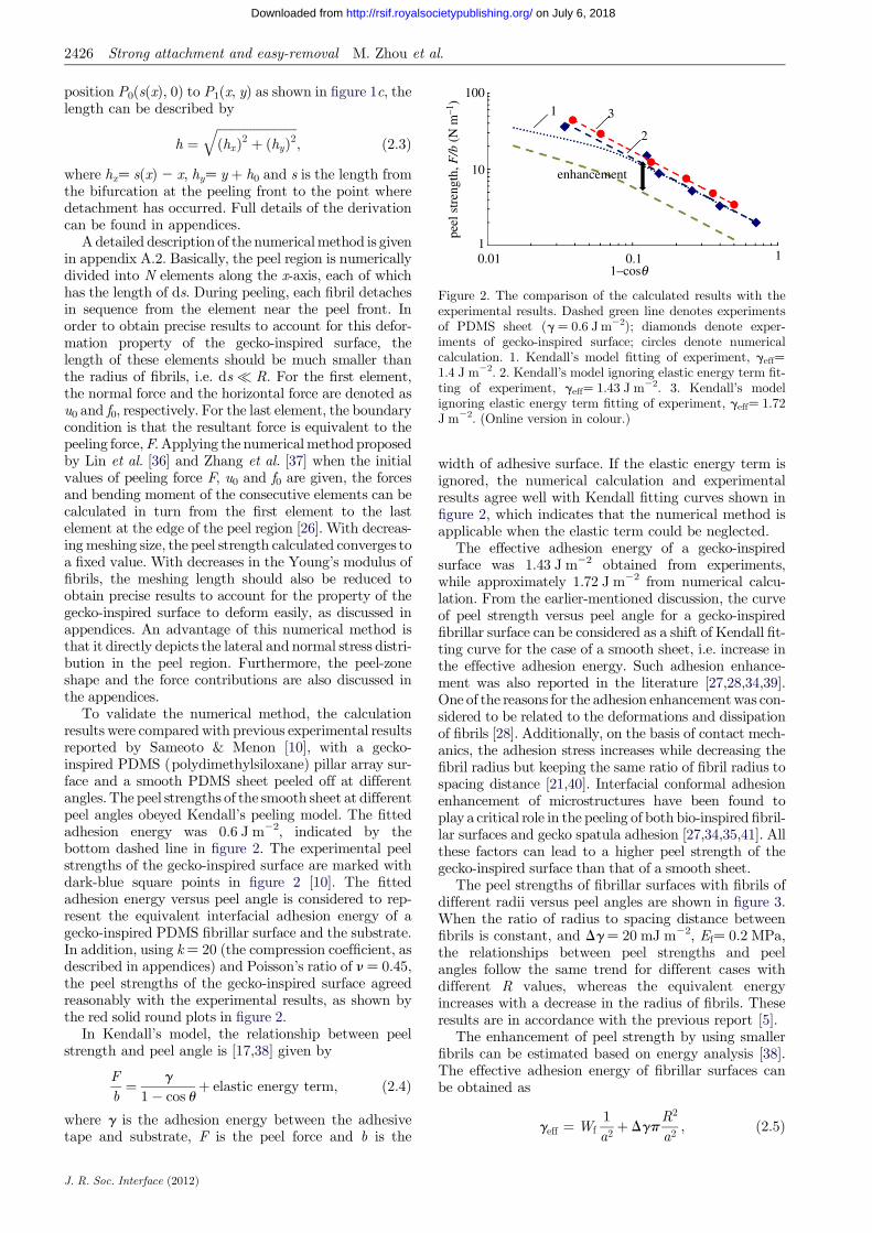
Figure 2. The comparison of the calculated results with theexperimental results. Dashed green line denotes experimentsof PDMS sheet (g ¼ 0.6 J m22); diamonds denote exper-iments of gecko-inspired surface; circles denote numericalcalculation. 1. Kendall’s model fitting of experiment, geff¼
1.4 J m22. 2. Kendall’s model ignoring elastic energy term fit-ting of experiment, geff¼ 1.43 J m22. 3. Kendall’s modelignoring elastic energy term fitting of experiment, geff¼ 1.72J m22. (Online version in colour.)
2426 Strong attachment and easy-removal M. Zhou et al.
on July 6, 2018http://rsif.royalsocietypublishing.org/Downloaded from
position P0(s(x), 0) to P1(x, y) as shown in figure 1c, thelength can be described by
h ¼ffiffiffiffiffiffiffiffiffiffiffiffiffiffiffiffiffiffiffiffiffiffiffiffiffiffiðhxÞ2 þ ðhyÞ2
q; ð2:3Þ
where hx¼ s(x) 2 x, hy¼ y þ h0 and s is the length fromthe bifurcation at the peeling front to the point wheredetachment has occurred. Full details of the derivationcan be found in appendices.
A detailed description of the numerical method is givenin appendix A.2. Basically, the peel region is numericallydivided into N elements along the x-axis, each of whichhas the length of ds. During peeling, each fibril detachesin sequence from the element near the peel front. Inorder to obtain precise results to account for this defor-mation property of the gecko-inspired surface, thelength of these elements should be much smaller thanthe radius of fibrils, i.e. ds� R. For the first element,the normal force and the horizontal force are denoted asu0 and f0, respectively. For the last element, the boundarycondition is that the resultant force is equivalent to thepeeling force, F. Applying the numerical method proposedby Lin et al. [36] and Zhang et al. [37] when the initialvalues of peeling force F, u0 and f0 are given, the forcesand bending moment of the consecutive elements can becalculated in turn from the first element to the lastelement at the edge of the peel region [26]. With decreas-ing meshing size, the peel strength calculated converges toa fixed value. With decreases in the Young’s modulus offibrils, the meshing length should also be reduced toobtain precise results to account for the property of thegecko-inspired surface to deform easily, as discussed inappendices. An advantage of this numerical method isthat it directly depicts the lateral and normal stress distri-bution in the peel region. Furthermore, the peel-zoneshape and the force contributions are also discussed inthe appendices.
To validate the numerical method, the calculationresults were compared with previous experimental resultsreported by Sameoto & Menon [10], with a gecko-inspired PDMS (polydimethylsiloxane) pillar array sur-face and a smooth PDMS sheet peeled off at differentangles. The peel strengths of the smooth sheet at differentpeel angles obeyed Kendall’s peeling model. The fittedadhesion energy was 0.6 J m22, indicated by thebottom dashed line in figure 2. The experimental peelstrengths of the gecko-inspired surface are marked withdark-blue square points in figure 2 [10]. The fittedadhesion energy versus peel angle is considered to rep-resent the equivalent interfacial adhesion energy of agecko-inspired PDMS fibrillar surface and the substrate.In addition, using k ¼ 20 (the compression coefficient, asdescribed in appendices) and Poisson’s ratio of n ¼ 0.45,the peel strengths of the gecko-inspired surface agreedreasonably with the experimental results, as shown bythe red solid round plots in figure 2.
In Kendall’s model, the relationship between peelstrength and peel angle is [17,38] given by
Fb¼ g
1� cos uþ elastic energy term; ð2:4Þ
where g is the adhesion energy between the adhesivetape and substrate, F is the peel force and b is the
J. R. Soc. Interface (2012)
width of adhesive surface. If the elastic energy term isignored, the numerical calculation and experimentalresults agree well with Kendall fitting curves shown infigure 2, which indicates that the numerical method isapplicable when the elastic term could be neglected.
The effective adhesion energy of a gecko-inspiredsurface was 1.43 J m22 obtained from experiments,while approximately 1.72 J m22 from numerical calcu-lation. From the earlier-mentioned discussion, the curveof peel strength versus peel angle for a gecko-inspiredfibrillar surface can be considered as a shift of Kendall fit-ting curve for the case of a smooth sheet, i.e. increase inthe effective adhesion energy. Such adhesion enhance-ment was also reported in the literature [27,28,34,39].One of the reasons for the adhesion enhancement was con-sidered to be related to the deformations and dissipationof fibrils [28]. Additionally, on the basis of contact mech-anics, the adhesion stress increases while decreasing thefibril radius but keeping the same ratio of fibril radius tospacing distance [21,40]. Interfacial conformal adhesionenhancement of microstructures have been found toplay a critical role in the peeling of both bio-inspired fibril-lar surfaces and gecko spatula adhesion [27,34,35,41]. Allthese factors can lead to a higher peel strength of thegecko-inspired surface than that of a smooth sheet.
The peel strengths of fibrillar surfaces with fibrils ofdifferent radii versus peel angles are shown in figure 3.When the ratio of radius to spacing distance betweenfibrils is constant, and Dg ¼ 20 mJ m22, Ef¼ 0.2 MPa,the relationships between peel strengths and peelangles follow the same trend for different cases withdifferent R values, whereas the equivalent energyincreases with a decrease in the radius of fibrils. Theseresults are in accordance with the previous report [5].
The enhancement of peel strength by using smallerfibrils can be estimated based on energy analysis [38].The effective adhesion energy of fibrillar surfaces canbe obtained as
geff ¼Wf1a2 þ Dgp
R2
a2 ; ð2:5Þ

0.01
0.1
1
0.01 0.1 1
peel
str
engt
h, F
/b (
N m
–1)
1 – cosq
Figure 3. The peel strength of fibrils with different radii versuspeel anglewhen the ratio of radius to the spacing of fibrils is con-stant. Solid line with diamonds (R ¼ 6 mm); solid line withsquares (R ¼ 9 mm); solid line with triangles (R ¼ 18 mm).(Online version in colour.)
Strong attachment and easy-removal M. Zhou et al. 2427
on July 6, 2018http://rsif.royalsocietypublishing.org/Downloaded from
where Wf is the maximum elastic energy of an individ-ual fibril prior to its detachment, and can be derived as
Wf;L , Wf , wf;maxpR2h0; ð2:6Þ
where Wf,L is the elastic energy of an individual fibrilfor linear elastic material and Wf,max is the maximumpossible elastic energy density for large neck shrinkdeformation. Full details of the derivation are givenin appendices.
The pull-off length h of fibrils by using thedetachment condition described in appendix A andequations (A 18–A 21) in appendix A can be appliedto determine the range of effective adhesion energy as1.06 J m22 , geff , 2.57 J m22, which concurs wellwith the results from the numerical calculations.
3. SURFACE DESIGN BASED ON PEELINGBEHAVIOURS
3.1. Geometrical design of fibrils
In order to achieve micro-fibrillar surfaces with reversiblepeeling, it is essential to combine the considerations ofstrong normal adhesion and optimized peeling beha-viours in the surface design principles. The earlier-mentioned discussion shows that the peel strengthincreases when the fibril radius decreases, with theratio of fibril radius to fibril spacing being kept constant.The enhancement of peel strength of the fibrillar surfaceobtained from the numerical method is shown in figure4a by taking typical values for the parameters in thenumerical analysis as u ¼ 308, Dg¼ 0.6 J m22, nf¼
0.45, h0¼ 10 mm, R/a ¼ 0.45, H ¼ 0.35 mm, where H isthe backing layer thickness of the fibrillar surface. How-ever, the normal adhesion stress of the gecko-inspiredsurface also increases when the fibril radius decreases,
J. R. Soc. Interface (2012)
with the ratio of fibril radius to fibril spacing beingkept constant, i.e.
sp ¼Pi
a2 ¼b2ffiffiffiffiRp
ffiffiffiffiffiffiffiffiffiffiffiffiffiffiffiffiffiffiffiffiffiffiffiffiffiffiffiffiffiffiffiffiffiffiffiffiffiffiffiffiffiffiffiffiffiffiffiffiffiffiffiffiffiffi8p
1� n2f
Efþ 1� n2
s
Es
� ��1
Dg
s; ð3:1Þ
where b ¼ R/a is the ratio of radius to spacing distancebetween fibrils. In addition, the normal adhesionstrength of a gecko-inspired surface can be expressed as
sp ¼lmPi
ðlaÞðmaÞ ; ð3:2Þ
where b and d are the width and length of thegecko-inspired surface, l ¼ b/a and m ¼ d/a, respectively.
As mentioned earlier, the peel force per unit width iscalled peel strength. The normal adhesion force per unitwidth, i.e. the so-called pull-off strength, is defined as
jp ¼lmPi
la¼ ma � sp
¼ db2ffiffiffiffiRp
ffiffiffiffiffiffiffiffiffiffiffiffiffiffiffiffiffiffiffiffiffiffiffiffiffiffiffiffiffiffiffiffiffiffiffiffiffiffiffiffiffiffiffiffiffiffiffiffiffiffiffiffiffiffi8p
1� n2f
Efþ 1� n2
s
Es
� ��1
Dg
s: ð3:3Þ
The gecko-inspired surface is expected to possessstrong attachment and easy-removal properties. Tocharacterize these properties, a parameter l is definedas follows:
l ¼jp
F=b; ð3:4Þ
where F/b is the ratio of the normal adhesion force perwidth (pull-off strength) to the peel strength. From thepeeling behaviour discussed earlier, the numericalresults obey F/b ¼ geff/(12cos u). Equation (3.4) canbe rewritten as
l ¼ db2ffiffiffiffiRp
geff
ffiffiffiffiffiffiffiffiffiffiffiffiffiffiffiffiffiffiffiffiffiffiffiffiffiffiffiffiffiffiffiffiffiffiffiffiffiffiffiffiffiffiffiffiffiffiffiffiffiffiffiffiffiffi8p
1� n2f
Efþ 1� n2
s
Es
� ��1
Dg
s� ð1
� cos uÞ¼ lr � dð1� cos uÞ; ð3:5Þ
where
lr ¼b2ffiffiffiffiRp
geff
ffiffiffiffiffiffiffiffiffiffiffiffiffiffiffiffiffiffiffiffiffiffiffiffiffiffiffiffiffiffiffiffiffiffiffiffiffiffiffiffiffiffiffiffiffiffiffiffiffiffiffiffiffiffi8p
1� n2f
Efþ 1� n2
s
Es
� ��1
Dg
s
is a reference value. Equation (3.5) indicates that l isrelated to physical parameters, including ðð1� n2
f =EfÞþð1� n2
s=EsÞÞ�1, Dg, the geometrical parameters andpeel angle. A larger l indicates better properties ofstrong adhesion and easy removal. The relationshipbetween lr and the radius of fibrils for cases with differentYoung’s modulus is shown in figure 4b. lr increases withan increase in the Young’s modulus and fibril radius.Therefore, the radius of fibrils should be designed inaccordance with material properties. When u ¼ 908,lr ¼ l/d, which indicates that the physical meaning oflr is l per length at the peel angle of 908.
Figure 4c shows that an increase in the lengthof fibrils is associated with an increase in the peel

0.5
1
2
4
8
16
32
1 2 4 8 16 0
5
10
15
20
25
30
0.5 1 1.5 2 2.5
peel
str
engt
h, F
/b (
N m
–1)
peel
str
engt
h, F
/b (
N m
–1)
peel
str
engt
h, F
/b (
N m
–1)
0
2000
4000
6000
8000
10 000
12 000
14 000
16 000
0
2
4
6
8
10
12
14
8 13 18 23 28
pull
off
stre
ss, x
p (N
m–1
)
60 000
240 000
960 000
3 840 000
8 13 18 23 28
(a)
(c) (d )
F/b (E = 2 MPa)
F/b (E = 8 MPa)
F/b (E = 16 MPa)
F/b (E = 2 MPa)
F/b (E = 8 MPa)
F/b (E = 16 MPa)
fibril radius, R (µm)fibril radius, R (µm)
F/b (E = 2 MPa) F/b (E = 8 MPa) F/b (E = 16 MPa) xp(E = 2 MPa) xp(E = 8 MPa)
lr (E = 2 MPa)
lr (E = 8 MPa)
lr (E = 16 MPa)
xp(E = 16 MPa)
(b)
fibril length, h0 (µm) aspect ratio, h0/R
l r
Figure 4. The influence of geometrical parameter on peel strength of gecko-inspired surface by taking typical parameters for u ¼308, Dg ¼ 0.6 J m22, nf ¼ 0.45, h0¼ 10 mm, R/a ¼ 0.45, H ¼ 0.35 mm. (a) The relationship between peel strength, pull-off stressjp and the radius of the fibril at different Young’s modulus. The solid points depict values of peel strength, whereas the hollowpoints indicate pull-off stress jp by choosing the typical value of equation (3.5) (b � 1022 m). (b) The relationship between lr andthe radius of fibrils at different Young’s modulus. (c) The peel strength versus the length of fibrils at different Young’s modulus offibrils. (d) The peel strength versus aspect ratio at different Young’s modulus of fibrils. (Online version in colour.)
2428 Strong attachment and easy-removal M. Zhou et al.
on July 6, 2018http://rsif.royalsocietypublishing.org/Downloaded from
strength, whereas the normal adhesion force does notchange according to equation (A 1). Figure 4d showsthat the relation of the peel strength of the gecko-inspired surface increases with the aspect ratio. Itshould be noted that fibrils cannot be too short owingto the roughness of actual substrate as very short fibrilscannot adapt to the roughness. Therefore, the rough-ness of the target substrates should be consideredwhen designing the length of fibril. Furthermore, anti-self-adhesion conditions should also be considered,which is given in §3.2.
On the basis of experimental results, Lamblet et al.[39] proposed that a correlation existed between theaspect of fibril and the peel strength of the gecko-inspired surface. During the peeling process, the elasticbending energy (Eb¼ 2P2h3/3pER4), the stretchingelastic energy (Ef¼ P2h/2pER3) and the deformationenergy of the substrate (Es¼ 8pP2/27ER) are fully dis-sipated. Therefore, the peel strength increases as theaspect ratio increases. However, when the aspect ratiois too large, the fibrils cannot resume their shapes fol-lowing peeling, or even form bundles, leading to adecrease in the peel strength. The earlier-mentioned
J. R. Soc. Interface (2012)
numerical method does not take Eb, Es and the bund-ling effect into account; thus, the method is notsuitable for gecko-inspired surfaces with large aspectratios. Therefore, anti-self-adhesion conditions shouldbe included to determine the critical aspect ratio [21],and then the numerical method can be applied todesign the geometrical parameters.
Previous studies have discussed the geometricaldesign. Spolenak et al. [24] and Gao et al. [29] discussedthe influence of the shape of the end of the fibril on theadhesion force. Zeng et al. [11] analysed the normaladhesion of inclined fibril by applying the JKR modeland van der Waals theory. The theoretical maximumadhesion force of a flat cylindrical fibril can be deter-mined by NFad ¼ Npr2A12=6pD3
0. Therefore, thesmaller the fibrils, the higher the normal adhesionforce. Zeng et al. [11] also analysed the relationshipbetween adhesion force and the incline angle of fibrils,and proposed that the normal adhesion force can bealtered by over two orders of magnitude. The previousstudies indicate a practical way to control the attach-ment and detachment of a gecko-inspired fibrillarsurface by varying the inclination angle.

1
10
100
1E – 05 1E – 04 1E – 03 1E – 02 1E – 01 1E + 00 1E + 01
300040005000600070008000900010 000
3.0
3.5
4.0
4.5
5.0
5 20 80
h0 = 200 µm
h0 = 100 µm
h0 = 50 µm
h0 = 10 µm
1
10
100
1E – 5 1E – 3 1E – 1 1E +11
10
100(a)
(c)
(b)
1E – 5 1E – 3 1E – 1 1E + 1
step 3:
inadaptabilitystep 1:
fibre fracture
step 2:
condensation
step 4:sapp<1 MPa
target areaoptimumpoint of sapp
lr = 2E6
lr = 3E6 (allowedin target area)
lr = 1E6
optimum pointof lr and sapp
Young’s modulus of fibres, Ef (GPa)
Young’s modulus of fibres, Ef (GPa)
Young’s modulus of fibres, Ef (GPa)
target area
fibr
il ra
dius
, R (
µm)
fibr
il ra
dius
, R (
µm)
fibr
il ra
dius
, R (
µm)
lr = 5E5
lr
lr allowedincreasing
xr
l r
sappallowedincreasing
length of fibres, h0(µm)‘conode’ points
pull
off
stre
ss, x
p (N
m–1
)
Figure 5. The adhesion and peeling design map with typical values for Dg ¼ 0.1 J m22, gf¼ 0.06 J m22, nf ¼ 0.45, R/a ¼ 0.45and H ¼ 0.35 mm, where gf is the work of adhesion between two fibrils. (a) The triangular target area, which is the optimizationof the gecko-inspired surface of h0¼ 10 mm. (b) lr obtained by the numerical method. (c) Further optimization of different fibrillengths, which is determined by the competition of the easy-removal property (increasing as the direction of the hollow arrow)and the strong adhesive property (increasing as the direction of the solid arrow). (Online version in colour.)
Strong attachment and easy-removal M. Zhou et al. 2429
on July 6, 2018http://rsif.royalsocietypublishing.org/Downloaded from
For a real gecko system, the adhesion force of geckoseta can be changed easily by more than three ordersof magnitude during attachment and detachment.The earlier-mentioned discussion and figure 4b indicatethat, under certain conditions, l ¼ lr.b(1 2 cos u), thechange of the peeling strength and the adhesionstrength can reach more than three orders of magni-tude. Therefore, on the basis of results in this study,the strong attachment and easy-removal properties ofgecko-inspired surfaces can be optimized by applyingthe design principle established based on the numericalmethod proposed.
3.2. Adhesion and peeling design map
The question of how to optimize the geometrical par-ameters of the fibrillar surfaces according to theirphysical properties has attracted widespread attention.Spolenak et al. [40] gave the optimization of the equiv-alent apparent contact strength. By taking typicalvalues for Dg ¼ 0.1 J m22, gf ¼ 0.06 J m22, nf ¼ 0.45,
J. R. Soc. Interface (2012)
h0¼ 10 mm, R/a ¼ 0.45 and H ¼ 0.35 mm, where gf
denotes the work of adhesion between two fibril tips,the optimization process can be summarized as follows.First, the fracture limit of a fibril with a flat end isexpressed as
R � 8EDg
pð1� n2Þsfth
2¼ 800Dg
pð1� n2ÞE ; ð3:6Þ
where sfth � E=10 is the theoretical fracture
strength. Second, the limit of fibril condensation andcontact adaptability of the flat end cylinder fibril isthe same as that of hemispherical end [40]. By takinga typical value for the fibril length h0¼ 10 mm, theselimits are shown in the respective shaded regimes infigure 5a. From equation (A 1) in appendix A, theequivalent apparent contact strength sapp¼ Pi/a2 con-dition is R ¼ 8EfDg=pð1� n2Þs2
app. The fourth step isto exclude the region where sapp , 1 MPa. Therefore,the remaining triangular target area gives the allowedparameter region for normal adhesion of an adhesivestructure with sapp of at least 1 MPa.

0.001
0.01
0.1
1
10
100
0.0001 0.001 0.01 0.1 1 10 100 1000
idea
l con
tact
fibre fracture
bioattachment
Young’s modulus of contact elements, Ef (GPa)
fibr
il ra
dius
, R (
µm)
h0 = 0.8 µm
h0 = 5 µm
h0 = 50 µm
‘conode’
s app
= 1
MPa
Figure 6. The allowed parameter for design of the attachmentelements of biological systems, where f ¼ pR2/a2¼ 10%, g ¼0.05 J m22. (Online version in colour.)
2430 Strong attachment and easy-removal M. Zhou et al.
on July 6, 2018http://rsif.royalsocietypublishing.org/Downloaded from
The design of surfaces with strong attachment andeasy-removal properties should be further optimized.Contours of constant lr can be obtained by the numeri-cal method, as shown in figure 5b. Only the segments onthese contours within the target area are allowed fordesign, at which the strong attachment and easy-removal properties are the same but sapp are different.The maximum sapp point is allowed at the intersectionof each equivalent lr condition line with the lowerborder of the triangular target area. Particularly, thepoint at the bottom of the triangular target area givesthe best optimum properties of lr and sapp.
By choosing the typical value of equation (3.5)(d � 1022 m, u ¼ 908), if lr is more than 105, thechange of the peeling strength and the adhesionstrength can reach three orders of magnitude. Further-more, figure 5c gives the target design area for cases ofdifferent fibril lengths, while the insets show the valuesof lr and sapp at the optimum points of different h0.With the increases in fibril length, smaller lr is allowedwithin the target area. Therefore, the direction of thehollow arrow represents that the easy-removal propertyallowed in the target area increases, whereas the direc-tion of the solid arrow represents that the strongadhesive property of the target area increases. Thecompetition of these two properties determines theoptimization of the gecko-inspired fibrillar surface.
The optimum parameters of normal adhesion that werementioned previously by Spolenak et al. [40] distributepoints of the triangular target areas at the bottom. How-ever, further optimization of these optimum points bythe actual requirement of the properties of strong adhesionand easy removal has not beendiscussed yet. Taking a typi-cal design as an example, for a material with the interfacialadhesion energy 0.1 J m22 with a substrate, the work ofadhesion between two fibrils 0.06 J m22, Poisson’s ratioof 0.45, the Young’s modulus of fibrils 32 MPa and thatof backing layer 2 MPa, the geometrical parameters,including the radius (2 mm), spacing distance (4.44 mm),and length of fibrils (10 mm) and also the thickness ofthe backing layer (0.35 mm), d¼ 5 � 1023 m and u¼
308, the change of the peeling strength and the adhesionstrength can reach over 2000 times and the adhesionstrength can reach 1.8 MPa, with no condensation andgood adaptability.
Therefore, by using the numerical calculation, theoptimum point to obtain a desired l can be selected. Pre-viously, Greiner et al. [42] proposed that the optimumpoint should be just at the intersection of the ‘conode’(shown as dashed dot line in figure 6) with the ideal con-tact strength limit (shown as dashed line in figure 6).However, by taking into account the strong attachmentand the easy-removal properties, the optimum pointis the balance of the two properties to some extent,which achieves qualitative agreement with the biologicalcontact elements (flies, beetles, spiders and lizards), asshown in figure 6 [40].
3.3. Design of backing layer
As expected, the numerical method can also be used todesign the backing layer. Kendall’s peeling model demon-strates that peel strength increases with increasing the
J. R. Soc. Interface (2012)
thickness, or Young’s modulus, of the backing layer,i.e. the stiffness of the backing layer [38]. For the gecko-inspired fibrillar surface, peel strength correlates with thestretch of fibrils. Equation (A 13) indicates that theshape of the peel region determines stretch or compressionof fibrils. Moreover, the deformation of fibrils influences thedeformation of the backing layer and then the shape of thepeel region. The theoretical results indicate that the influ-ence of backing layer thickness on the peel strength of thegecko-inspired fibrillar surface is similar to the prediction ofKendall’s peeling model for a smooth sheet; however, theincrease rate, i.e. the derivative of peel strength withrespect to the backing layer thickness, is not the same asthat predicted by the model (figure 7a). In Kendall’s peel-ing model, for a smooth elastic thin film, only the elasticdeformation energy of the backing layer, which increaseswith the backing layer thickness, influences the peelstrength. However, for the gecko-inspired micro-fibrillarsurface, the deformation of the backing layer determinesthe length of the peel-zone and the peel strength. There-fore, the peel strength, the effective adhesion energy andthen lr change with different backing layer thicknesses.According to equation (3.5), the strong attachment andeasy-removal properties of parameter l is inversely pro-portional to the effective adhesion energy; so theminimum backing layer thickness leading to the best per-formance can be achieved under the condition thatfracture of the backing layer does not occur.
The stiffness of backing layer can be given by
E�I ¼ E1� n2
bH 3
12; ð3:7Þ
where I is the moment of inertia, E* ¼ E/(12n2).Therefore, the influence of modulus of the backing layer
is the same as that of H3, whereas in Kendall’s model, theinfluence of thickness of backing is the same as that of E*.It is important to note that the earlier-mentioned discus-sions consider only the bending of the backing layerwithout including extension deformation. The peel

230 000
235 000
240 000
245 000
250 000
0.1 1 104.0
4.1
4.2
4.3
4.4
4.5
12.3
12.8
13.3
0 2 4 6backing layer thickness, H (mm)
peel
str
engt
h, F
/b (
N m
–1)
peel
str
engt
h, F
/b (
N m
–1)
(b) (a)
backing layer thickness, H (mm)
l r
Figure 7. The influence of the backing layer thickness on the peel strength of the gecko-inspired surface by taking typical par-ameters for u ¼ 308, Dg ¼ 0.6 J m22, nf ¼ 0.45, h0 ¼ 10 mm and R/a ¼ 0.45. (a) The peel strength versus backing layerthickness. (b) lr at different backing layer thicknesses. Solid line circles denote numerical calculation; solid line with diamondsdenote Kendall’s model. (Online version in colour.)
Strong attachment and easy-removal M. Zhou et al. 2431
on July 6, 2018http://rsif.royalsocietypublishing.org/Downloaded from
strength may, in actuality, be overvalued when the peelangle or the Young’s modulus of backing layer are small.
4. CONCLUSIONS
In this study, a numerical method was proposed to investi-gate the effect of peel-zone on the peeling behaviour offibrillar surfaces. The strong attachment and easy-removalproperties, and also the effect of the geometrical par-ameters of fibrils and the backing layer stiffness onthe peel-zone and the peel strength are all theoreticallyevaluated by using the numerical method proposed. Theadhesion and peeling design maps are developed for bio-inspired attachment systems by taking account of the peel-ing behaviours. The numerical analysis showed that theoptimization of the gecko-inspired surface is determinedby the competition between the easy-removal propertyand the strong adhesive property to some extent, whichachieves qualitative agreement with the biological contactelements. By choosing some typical values, the peelingstrength and adhesion strength can vary by over threeorders of magnitude. The adhesion and peeling designmap established provides new insights into the design anddevelopment innovative gecko-inspired fibrillar surfaces.
This work is sponsored by the Natural Science Foundation ofChina (grant no. 51175281) and the National Basic ResearchProgram of China (grant no. 2011CB707603). N.S.P. issupported by a PFund grant through the Louisiana Boardof Regents. H.Z. acknowledges the support of the Universityof Alberta China Opportunity Fund and an NSERCDiscovery Grant Award from the Natural Sciences andEngineering Research Council of Canada. We also thanktwo anonymous reviewers for helpful comments.
APPENDIX A. PEELING MODEL OFGECKO-INSPIRED SURFACE
A.1. Mechanical model at peel region
For a gecko-inspired surface with regular cylindricalfibrils, the radius of fibrils can be defined as R, the
J. R. Soc. Interface (2012)
spacing as a and the height as h0, as shown infigure 1. When these fibrils detach from the smooth sub-strate, based on contact mechanics, the pull-off force ofan individual fibril, denoted as vertical flat pillars Pi,can be approximated as [29,43]
Pi ¼
ffiffiffiffiffiffiffiffiffiffiffiffiffiffiffiffiffiffiffiffiffiffiffiffiffiffiffiffiffiffiffiffiffiffiffiffiffiffiffiffiffiffiffiffiffiffiffiffiffiffiffiffiffiffiffiffiffiffiffiffi8pR3 1� n2
f
Efþ 1� n2
s
Es
� ��1
Dg
s; ðA 1Þ
where Ef and Es are the Young’s modulus of fibrils andthe substrate, respectively; nf and ns are Poisson’s ratioof fibrils and the substrate, respectively; Dg ¼ gf þ gs2
gf,s is the work of adhesion between fibrils and the sub-strate, gf, gs, gf,s denote surface and interfacial energiesof fibrils and the substrate. Therefore, the pull-off stressof an individual fibril is [40]
sM ¼Pi
pR2 ¼1ffiffiffiffiffiffiffipRp
ffiffiffiffiffiffiffiffiffiffiffiffiffiffiffiffiffiffiffiffiffiffiffiffiffiffiffiffiffiffiffiffiffiffiffiffiffiffiffiffiffiffiffiffiffiffiffiffiffiffiffi8
1� n2f
Efþ 1� n2
s
Es
� ��1
Dg
s: ðA 2Þ
When the gecko-inspired surface is peeled off of a sub-strate at a certain angle, the fibrils stretch and deformuntil the tension stress exceeds the pull-off stress anddetach from the smooth substrate, as shown in figure 1c.With a large deformation, the relationship between strainand length of the fibril can be described as follows [44]:
d ¼ðh
h0
dhh¼ ln
hh0: ðA 3Þ
When fibrils are stretched, the neck becomes thinner,as shown in figure 1c. At the neck of fibrils, the relation-ship between stress and strain follows Hooke’s Laws:
sn ¼ Efd: ðA 4Þ
The area of the fibril end does not change prior todetachment, as the end of the fibril is continuouslyadherent to the substrate. Furthermore, the volumeof the fibril Vf does not change, and therefore anapproximate value can be obtained by
Vf ¼ Ah0 � Anh: ðA 5Þ

(b)
x
ds
fifi –1
ui
ui –1
ds fj
uj –1sj
dsfN
uNujpeel force: F
the ith element
the jth element
y
z
x
ds
trapezoid areaapproximation
fj –1
(a)
Figure 8. A schematic of force analysis of typical elements of gecko-inspired surface. (a) A schematic side view of the elementswith/without fibril segments. (b) A schematic bottom view of elements. For each element with a fibril segment, the area of tensileor compression stress is approximately equal to the trapezoidal area constituted by the borders of the element and the Arcsecants. (Online version in colour.)
2432 Strong attachment and easy-removal M. Zhou et al.
on July 6, 2018http://rsif.royalsocietypublishing.org/Downloaded from
The forces at the end and the neck remain the same,denoted by P, and thus, the stress at the end and theneck can be expressed, respectively, as
sn ¼PAn
; ðA 6Þ
and
sf ¼PA: ðA 7Þ
Combining equations (A 3–A 7), the relationshipbetween stress at the end and the length of the fibrilcan be determined as
sf ¼ Efh0
hln
hh0: ðA 8Þ
Alternatively, when the fibril is compressed, thecompression modulus becomes larger with an increase
J. R. Soc. Interface (2012)
in compression, usually described as an exponentialrelationship
sf ¼ ekðh0�hÞ=h0Efh0
hln
hh0; ðA 9Þ
where k is the compression coefficient.From figure 1c, the length of the deformed fibril
appears to be related to its displacement along x- andy-axes. When the upper end of the fibril moves fromP0(s(x),0) to P1(x, y), the length can be described asfollows:
h ¼ffiffiffiffiffiffiffiffiffiffiffiffiffiffiffiffiffiffiffiffiffiffiffiffiffiffiðhxÞ2 þ ðhyÞ2
q; ðA 10Þ
where hx¼ s(x) 2 x, hy¼ y þ h0 and s is the length fromthe bifurcation at the peeling front to the point wheredetachment has occurred. Therefore,
sf ¼
h0ffiffiffiffiffiffiffiffiffiffiffiffiffiffiffiffiffiffiffiffiffiffiffiffiffiffiðhxÞ2 þ ðhyÞ2
q Ef ln
ffiffiffiffiffiffiffiffiffiffiffiffiffiffiffiffiffiffiffiffiffiffiffiffiffiffiðhxÞ2 þ ðhyÞ2
qh0
hi . h0
0 hi ¼ h0
ekh0�
ffiffiffiffiffiffiffiffiffiffiffiffiffiffiðhx Þ2þðhy Þ2p
h0h0ffiffiffiffiffiffiffiffiffiffiffiffiffiffiffiffiffiffiffiffiffiffiffiffiffiffi
ðhxÞ2 þ ðhyÞ2q Ef ln
ffiffiffiffiffiffiffiffiffiffiffiffiffiffiffiffiffiffiffiffiffiffiffiffiffiffiðhxÞ2 þ ðhyÞ2
qh0
hi � h0
ðA 11Þ
8>>>>>>>>>><>>>>>>>>>>:
When sf¼ Pi/pR2, the fibril detaches from thesubstrate. Pi is given by equation (A 1).
A.2. Numerical method
The peel region is divided into N elements along the x-axis, each length of which is ds. During peeling, eachfibril detaches simultaneously from the element nearthe peel front. Therefore, the length of these elementsshould be smaller than the radius of fibrils, i.e.ds� R. Figure 8 presents the schematic of meshing.For each element of these fibrils, the area of tensile orcompression stress is approximately equal to the
trapezoidal area constituted by the borders of theelement and the Arc secants, as shown in figure 8b.
The force analysis of elements, with or without somepart of the fibril, is shown in figure 8a. In general, thebending stress is much smaller than tensile or compres-sion stresses in instances of large tensile or compressiondeformation. Therefore, the bending moment of thefibril can be ignored in order to simplify the calculation.In the following equation (A 13), the equivalent stress ofeach element can be determined as the product of thestress of the fibril at this element with the area fractionof stress.
0
2
4
6
8
10
12
14
1 10 100 1000
peel
str
engt
h, F
/b (
N m
–1)
compression coefficient, k
peel angle: 30°
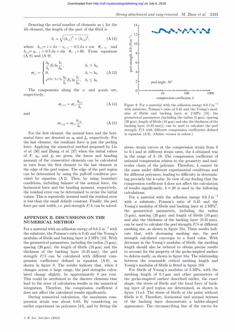
Figure 9. For a material with the adhesion energy 0.6 J m22
with substrate, Poisson’s ratio of 0.45 and the Young’s mod-ulus of fibrils and backing layer at 2 MPa [10], thegeometrical parameters (including the radius (5 mm), spacing(20 mm), length of fibrils (10 mm) and also the thickness of thebacking layer (0.35 mm)), can be used to calculate the peelstrength F/b with different compression coefficients definedin equation (A 9). (Online version in colour.)
Strong attachment and easy-removal M. Zhou et al. 2433
on July 6, 2018http://rsif.royalsocietypublishing.org/Downloaded from
Denoting the serial number of elements as i, for theith element, the length of the part of the fibril is
hi ¼ffiffiffiffiffiffiffiffiffiffiffiffiffiffiffiffiffiffiffiffiffiffiffiffiffiffiffiffiffiffiðhi;xÞ2 þ ðhi;yÞ2
q; ðA 12Þ
where hix¼ i � ds 2 xi21 2 0.5 ds � cos ui2 1, andhiy¼ yi2 1 þ 0.5 ds � sin ui2 1þh0. From equations(A 8) and (A 9)
sf;i ¼
h0
hiEf ln
hi
h0; hi . h0;
0; hi ¼ h0;
ekðh0�hiÞ=h0h0
hiEf ln
hi
h0; hi � h0:
8>>>><>>>>:
ðA 13Þ
The components along the x- and y-axis are,respectively,
sf;i;x ¼ sf;ihi;x
hiðA 14Þ
and
sf;i;y ¼ sf;ihi;y
hi: ðA 15Þ
For the first element, the normal force and the hori-zontal force are denoted as u0 and f0, respectively. Forthe last element, the resultant force is just the peelingforce. Applying the numerical method proposed by Linet al. [36] and Zhang et al. [37] when the initial valuesof F, u0, and f0 are given, the forces and bendingmoment of the consecutive elements can be calculatedin turn from the first element to the last element atthe edge of the peel region. The edge of the peel regioncan be determined by using the pull-off condition pro-vided by equation (A 2). Then, by using boundaryconditions, including balance of the normal force, thehorizontal force and the bending moment, respectively,the residual error can be determined to revise the initialvalues. This is repeatedly iterated until the residual erroris less than the small default constant. Finally, the peelforce per unit width, i.e. peel strength F/b, can be solved.
APPENDIX B. DISCUSSIONS ON THENUMERICAL METHOD
For a material with an adhesion energy of 0.6 J m22 withthe substrate, the Poisson’s ratio is 0.45 and the Young’smodulus of fibrils and backing layer is 2 MPa [10]. Withthe geometrical parameters, including the radius (5 mm),spacing (20 mm), the length of fibrils (10 mm) and thethickness of the backing layer (0.35 mm), the peelstrength F/b can be calculated with different com-pression coefficients defined in equation (A 9), asshown in figure 9. The results indicate that, when kchanges across a large range, the peel strengths calcu-lated change slightly, by approximately 8 per cent.This could be attributed to the discrete elements thatlead to the error of calculation results in the numericalintegration. Therefore, the compression coefficient kdoes not affect the calculated results significantly.
During numerical calculation, the maximum com-pression strain was about 0.05. By considering anearlier experiment on polymers [44], and by fitting the
J. R. Soc. Interface (2012)
stress–strain curves at the compression strain from 0to 0.1 and at different strain rates, the k obtained wasin the range of 3–19. The compression coefficient ofuniaxial compression relates to the geometry and mol-ecular chain of the polymer. Therefore, k cannot bethe same under different experimental conditions andfor different polymers, leading to difficulty in determin-ing precisely the k-value. In view of our finding that thecompression coefficient k does not affect the calculationof results significantly, k ¼ 20 is used in the followingcalculations.
For a material with the adhesion energy 0.6 J m22
with a substrate, Poisson’s ratio of 0.45 and theYoung’s modulus of fibrils and backing layer at 2 MPa8,the geometrical parameters, including the radius(5 mm), spacing (20 mm) and length of fibrils (10 mm)and also the thickness of the backing layer (0.35 mm),can be used to calculate the peel strength F/b at differentmeshing size, as shown in figure 10a. These results indi-cate that, with decreasing meshing size, the peelstrength calculated converges to a fixed value. Withdecreases in the Young’s modulus of fibrils, the meshinglength should also be reduced to obtain precise resultsto account for the property of the gecko-inspired surfaceto deform easily, as shown in figure 10a. The relationshipbetween the reasonable critical meshing length andYoung’s modulus of fibrils is fitted in figure 10b.
For fibrils of Young’s modulus of 3 MPa, with themeshing length of 0.1 mm and other parameters ofthe gecko-inspired surface described earlier, the exactshape, the stress of fibrils and the local force of back-ing layer of peel region are determined, as shown infigure 11a,b. The stress of fibrils at the point withoutfibrils is 0. Therefore, horizontal and normal stressesof the backing layer demonstrate a ladder-shapedappearance. The circumscribing line of the curves for

1
2
4
8
16
0.002 0.02 0.2 2
peel
str
engt
h, F
/b (
N m
–1)
32 MPa 16 MPa
8 MPa 6 MPa
4 MPa 3 MPa
ds = 0.0249 Ef 0.6628
0
0.05
0.10
0.15
0.20
0.25
0.30
10 20 30
peel angle: 30°
peel angle: 30°
criti
cal m
inim
um o
f ds
(µm
)
(b)(a)
ds/R Young's modulus of fibres, Ef (MPa)
Figure 10. For a material with the adhesion energy 0.6 J m22 with substrate, Poisson’s ratio of 0.45 and the Young’s modulus ofbacking layer at 2 MPa [10], the geometrical parameters (including the radius (5 mm), spacing (20 mm), length of fibrils (10 mm)and also the thickness of the backing layer (0.35 mm)), can be used to calculate the effect of meshing length on the peel strengthF/b. (a) The peel strength F/b calculated at different length meshing. (b) The fitting relationship between the reasonable criticalmeshing length and the Young’s modulus of fibrils. (Online version in colour.)
–9.8
–9.7
–9.6
–9.5
–10
–5
0
5
10
15
20
25
500 800 1100 1400
vert
ical
for
ce p
er w
idth
, v/b
(N
m–1
)
peel angle: 30°
–1
1
3
5
7
9
11
900 950 1000 1050 1100 200
210
220
230
240
0
3
6
9
20 40 60 80 100
peel
zon
e le
ngth
(µm
)
peel angle, q (°)
–1
–0.5
0
0.5
1.0
1.5
–2
0
2
4
6
8
10
12
14
500 800 1100 1400
peel angle: 30°
peel angle: 30°
norm
al c
ompo
nent
of
peel
stre
ngth
, F/b
× si
nq (
N m
–1)
(d)
x (µm)x (µm)ho
rizo
ntal
for
ce p
er w
idth
, F/b
(N
m–1
)
stre
ss o
f fi
bres
, sf
(MPa
)
(b)(a)
y (µ
m)
(c)
x (µm)
y (µ
m)
Figure 11. Results calculated for a material with adhesion energy of 0.6 J m22 with substrate, the Poisson’s ratio of 0.45, the Young’smodulus of backing layer of 2 MPa and the Young’s modulus of fibrils of 3 MPa, by using the geometrical parameter of the radius(5 mm) of fibrils are depicted here. (a) The shape of the peel region and force distribution. Forces greater than zero indicate that thefibril is stretched, and values less than zero indicate that the fibril is compressed (red curve denotes peel zone shapes; blue curvedenotes stress of fibres). (b) The normal and horizontal stress per width of the backing layer. The forward directions of thenormal and horizontal stresses are the same as the y, x direction, respectively, shown in figure 8 (purple curve denotes verticalstress of backing layer; red curve denotes horizontal stress of backing layer). (c) The apparent peel-zone of numerical calculationand its circular approximation (blue curve denotes numerical calculation; red curve denotes the circular approximation). (d) Atdifferent peeling angles, the normal component of peel strength and the apparent peel-zone length are presented here (blue circlesdenote normal component of peel strength; red triangles denote the peel zone length). (Online version in colour.)
2434 Strong attachment and easy-removal M. Zhou et al.
J. R. Soc. Interface (2012)
on July 6, 2018http://rsif.royalsocietypublishing.org/Downloaded from
Strong attachment and easy-removal M. Zhou et al. 2435
on July 6, 2018http://rsif.royalsocietypublishing.org/Downloaded from
stress of fibrils plotted against x is similar to the stressdistribution of pressure-sensitive adhesive tape duringpeeling that was calculated by Plaut & Ritchie [45].Furthermore, these results indicate that the length ofthe peel region is about 1 mm, and comprises twoparts: a compression region where fibrils are compressedand the apparent peel-zone where fibrils are stretched.The apparent peel-zone can be observed intuitively inexperiments, and has been discussed and analysedin several articles [17,30,32,36,45]. The shape of theapparent peel-zone can be calculated by the earlier-mentioned numerical method and is approximatelyequivalent to a circular shape as shown in figure 11c,which in accordance with the microscopic observationreported by Pesika et al. [17]. However, it is difficultto observe the compression region of peel region, asthere is only a slight deformation [46]. An advantageof this numerical method is that it depicts the distri-bution of several physical quantities at the peel regiondirectly. Furthermore, the apparent peel-zone lengthsat different peeling angles are shown in figure 11d.The trend in these lengths is consistent with thenormal component of peel strength. This indicatesthat the apparent peel-zone determines the adhesivepeel force, which is accordance with the report byPesika et al. [17] and Peng et al. [26].
APPENDIX C. ENERGY ANALYSIS ON THEPEELING BEHAVIOURS
During peeling, each fibril is stretched and the elastictensile stress increases until it exceeds the pull-offstress. As the fibrils are very small, the parameters,such as numbers of fibrils, the deformation of fibrilsand substrate and so on, can be considered to be thesame during the peeling process—i.e. with the sameelastic energy of the peel region Therefore, after peelingthe gecko-inspired surface with a length Dc, the dissi-pated elastic energy is actually the maximum elasticenergy of the fibrils stored in the peel-zone (the gecko-inspired surface with the length of Dc) prior to theirdetaching from the substrate. On the basis of earlier-mentioned analysis, the energy balance equation canbe described as follows:
Fð1� cos uÞDc þ 12
F2
bH;EDc
¼WfbDca2 þ Dgp
R2
a2 bDc; ðA 16Þ
where Wf is the maximum elastic energy of an individ-ual fibril prior to its detachment, and WfbDc/a2 is thedissipative elastic energy term. Equation (A 16) canbe simplified as
Fbð1� cos uÞ þ 1
2ðF=bÞ2
HE¼Wf
1a2 þ Dgp
R2
a2 : ðA 17Þ
As a comparison with Kendall’s equation, theeffective adhesion energy of fibrillar surfaces is
geff ¼Wf1a2 þ Dgp
R2
a2 : ðA 18Þ
J. R. Soc. Interface (2012)
For the linear elastic material,
Wf;L ¼ P2h=2pER3: ðA 19Þ
The linear elastic deformation may actually occuronly in a small area very close to the upper and thebottom ends of the fibril. At the neck of the fibril,there is a large neck shrink deformation. The maximumpossible elastic energy density wf,max is
wf;max ¼ðh
h0
Efddhh
¼ Ef12ðln hÞ2 � Ef ln h0 ln h þ Ef
12ðln h0Þ2;
ðA 20Þ
where d is described as equation (A 4). The actualdeformation is complex, non-uniform. Therefore, Ef
is in the range between those predicted in theearlier-mentioned two cases and is described as follows:
Wf;L , Wf , wf;maxpR2h0: ðA 21Þ
REFERENCES
1 Dickrell, P. L., Sinnott, S. B., Hahn, D. W., Raravikar, N.R., Schadler, L. S., Ajayan, P. M. & Sawyera, W. G. 2005Frictional anisotropy of oriented carbon nanotubesurfaces. Tribol. Lett. 18, 59–62. (doi:10.1007/s11249-004-1752-0)
2 Lee, H., Lee, B. P. & Messersmith, P. B. 2007 A reversiblewet/dry adhesive inspired by mussels and geckos. Nature448, 334–338. (doi:10.1038/nature05968)
3 Liley, M. et al. 1998 Friction anisotropy and asymmetry of acompliant monolayer induced by a small molecular tilt.Science 280, 273–275. (doi:10.1126/science.280.5361.273)
4 Qu, L., Dai, L., Stone, M., Xia, Z. & Wang, Z. L. 2008Carbon nanotube arrays with strong shear binding-onand easy normal lifting-off. Science 322, 238–242.(doi:10.1126/science.1159503)
5 Arzt, E., Gorb, S. & Spolenak, R. 2003 From micro tonano contacts in biological attachment devices. Proc.Natl Acad. Sci. USA 100, 10 603–10 606. (doi:10.1073/pnas.1534701100)
6 Gao, H. J. & Yao, H. M. 2004 Shape insensitive optimaladhesion of nanoscale fibrillar structures. Proc. NatlAcad. Sci. USA 101, 7851–7856. (doi:10.1073/pnas.0400757101)
7 Geim, A. K., Dubonos, S. V., Grigorieva, I. V., Novoselov,K. S., Zhukov, A. A. & Shapoval, S. Y. 2003 Microfabri-cated adhesive mimicking gecko foot-hair. Nat. Mater. 2,461–463. (doi:10.1038/nmat917)
8 Glassmaker, N. J., Jagota, A., Hui, C. Y. & Kim, J. 2011Design of biomimetic fibrillar interfaces: 1. Making con-tact. J. R. Soc. Interface 1, 23–33. (doi:10.1098/rsif.2004.0004)
9 Gorb, S., Varenberg, M., Peressadko, A. & Tuma, J. 2007Biomimetic mushroom-shaped fibrillar adhesive micro-structure. J. R. Soc. Interface 4, 271–275. (doi:10.1098/rsif.2006.0164)
10 Sameoto, D. & Menon, C. 2009 Direct molding of dryadhesives with anisotropic peel strength using an offsetlift-off photoresist mold. J. Micromech. Microeng. 19,1–5. (doi:10.1088/0960-1317/19/11/115026)
11 Zeng, H. B., Pesika, N., Tian, Y., Zhao, B. X., Chen, Y. F.,Tirrell, M., Turner, K. L. & Israelachvili, J. N. 2009

2436 Strong attachment and easy-removal M. Zhou et al.
on July 6, 2018http://rsif.royalsocietypublishing.org/Downloaded from
Frictional adhesion of patterned surfaces and implicationsfor gecko and biomimetic systems. Langmuir 25, 7486–7495. (doi:10.1021/la900877h)
12 Zhao, B. X., Pesika, N., Zeng, H. B., Wei, Z. S., Chen, Y.F., Autumn, K., Turner, K. & Israelachvili, J. 2009 Role oftilted adhesion fibrils (setae) in the adhesion and loco-motion of gecko-like systems. J. Phys. Chem. B 113,3615–3621. (doi:10.1021/jp806079d)
13 Verdier, C., Piau, J. M. & Benyahia, L. 1998 Peeling ofacrylic pressure sensitive adhesives: cross-linked versusuncross-linked adhesives. J. Adhesion 68, 93–116.(doi:10.1080/00218469808029581)
14 Wei, Y. & Hutchinson, J. W. 1998 Interface strength, workof adhesion and plasticity in the peel test. Int. J. Fracture93, 315–333. (doi:10.1023/A:1007545200315)
15 Lee, S., Jensen, L. & Langford, S. 1995 Electrical transi-ents generated by the peel of a pressure sensitiveadhesive tape from a copper substrate. J. Adhes. Sci.Technol. 9, 1–26. (doi:10.1163/156856195X00266)
16 Autumn, K., Dittmore, A., Santos, D., Spenko, M. &Cutkosky, M. 2006 Frictional adhesion: a new angle ongecko attachment. J. Exp. Biol. 209, 3569–3579. (doi:10.1242/jeb.02486)
17 Pesika, N. S., Tian, Y., Zhao, B. X., Rosenberg, K., Zeng,H. B., McGuiggan, P., Autumn, K. & Israelachvili, J. N.2007 Peel-zone model of tape peeling based on the geckoadhesive system. J. Adhesion 83, 383–401. (doi:10.1080/00218460701282539)
18 Tian, Y., Pesika, N., Zeng, H. B., Rosenberg, K., Zhao, B.X., McGuiggan, P., Autumn, K. & Israelachvili, J. 2006Adhesion and friction in gecko toe attachment and detach-ment. Proc. Natl Acad. Sci. USA 103, 19 320–19 325.(doi:10.1073/pnas.0608841103)
19 Persson, B. 2003 On the mechanism of adhesion in biologi-cal systems. J. Chem. Phys. 118, 7614–7621. (doi:10.1063/1.1562192)
20 Persson, B. & Gorb, S. 2003 The effect of surface rough-ness on the adhesion of elastic plates with application tobiological systems. J. Chem. Phys. 119, 11 437–11 444.(doi:10.1063/1.1621854)
21 Autumn, K. et al. 2002 Evidence for van der waalsadhesion in gecko setae. Proc. Natl Acad. Sci. USA 99,12 252–12 256. (doi:10.1073/pnas.192252799)
22 Chen, S. H. & Gao, H. J. 2007 Bio-inspired mechanics ofreversible adhesion: orientation-dependent adhesionstrength for non-slipping adhesive contact with transver-sely isotropic elastic materials. J. Mech. Phys. Solids 55,1001–1015. (doi:10.1016/j.jmps.2006.10.008)
23 Dai, Z. D., Tong, J. & Ren, L. Q. 2006 Researches anddevelopments of biomimetics in tribology. Chinese Sci.Bull. 51, 2681–2689. (doi:10.1007/s11434-006-2184-z)
24 Gao, H. J., Wang, X., Yao, H. M., Gorb, S. & Arzt, E.2005 Mechanics of hierarchical adhesion structures ofgeckos. Mech. Mater. 37, 275–285. (doi:10.1016/j.mechmat.2004.03.008)
25 Glass, P., Chung, H. Y., Washburn, N. R. & Sitti, M.2009 Enhanced reversible adhesion of dopamine methacryla-mide-coated elastomer microfibrillar structures under wetconditions. Langmuir 25, 6607–6612. (doi:10.1021/la9009114)
26 Peng, Z. L., Chen, S. H. & Soh, A. K. 2010 Peeling behav-ior of a bio-inspired nano-film on a substrate. Int. J. SolidsStruct. 47, 1952–1960. (doi:10.1016/j.ijsolstr.2010.03.035)
27 Shahsavan, H. & Zhao, B. X. 2011 Conformal adhesionenhancement on biomimetic microstructured surfaces.Langmuir 27, 7732–7742. (doi:10.1021/la200893n)
28 Poulard, C., Restagno, F., Weil, R. & Leger, L. 2011 Mech-anical tuning of adhesion through micro-patterning of
J. R. Soc. Interface (2012)
elastic surfaces. Soft Matter 7, 2543–2551. (doi:10.1039/c0sm01099e)
29 Spolenak, R., Gorb, S., Gao, H. J. & Arzt, E. 2005Effects of contact shape on the scaling of biological attach-ments. Proc. R. Soc. A 461, 305–319. (doi:10.1098/rspa.2004.1326)
30 Cheng, Q. H., Chen, B., Gao, H. J. & Zhang, Y. W. 2011Sliding-induced non-uniform pretension governs robustand reversible adhesion: a revisit of adhesion mechanismsof geckos. J. R. Soc. Interface 9, 283–291. (doi:10.1098/rsif.2011.0254)
31 Georgiou, I., Hadavinia, H., Ivankovic, A., Kinloch, A. J.,Tropsa, V. & Williams, J. G. 2003 Cohesive zone modelsand the plastically deforming peel test. J. Adhesion 79,239–265. (doi:10.1080/00218460390148121)
32 Pugno, N. M. 2011 The theory of multiple peeling.Int. J. Fract. 171, 185–193. (doi:10.1007/s10704-011-9638-2)
33 Ghatak, A., Mahadevan, L., Chung, J. Y., Chaudhury, M.K. & Shenoy, V. 2004 Peeling from a biomimetically pat-terned thin elastic film. Proc. R. Soc. Lond. A 460,2725–2735. (doi:10.1098/rspa.2004.1313)
34 Mahdavi, A. et al. 2008 A biodegradable and biocompati-ble gecko-inspired tissue adhesive. Proc. Natl Acad. Sci.USA 105, 2307–2312. (doi:10.1073/pnas.0712117105)
35 Vajpayee, S., Khare, K., Yang, S., Hui, C. Y. & Jagota, A.2011 Adhesion selectivity using rippled surfaces. Adv.Funct. Mater. 21, 547–555. (doi:10.1002/adfm.201001652)
36 Lin, Y. Y., Hui, C. Y. & Wang, Y. C. 2002 Modeling thefailure of an adhesive layer in a peel test. J. Polym. Sci.Pol. Phys. 40, 2277–2291. (doi:10.1002/polb.10289)
37 Zhang, L.& Wang, J. 2009 Ageneralized cohesive zone modelof the peel test for pressure-sensitive adhesives. Int. J. Adhes.Adhes. 29, 217–224. (doi:10.1016/j.ijadhadh.2008.05.002)
38 Kendall, K. 1975 Thin-film peeling: the elastic term.J. Phys. D Appl. Phys. 8, 1449–1452. (doi:10.1088/0022-3727/8/13/005)
39 Lamblet, M., Verneuil, E., Vilmin, T., Buguin, A.,Silberzan, P. & Leger, L. 2007 Adhesion enhancementthrough micropatterning at polydimethylsiloxane–acrylicadhesive interfaces. Langmuir 23, 6966–6974. (doi:10.1021/la063104h)
40 Spolenak, R., Gorb, S. & Arzt, E. 2005 Adhesion designmaps for bio-inspired attachment systems. Acta Biomater.1, 5–13. (doi:10.1016/j.actbio.2004.08.004)
41 Canas, N., Kamperman, M., Voelker, B., Kroner, E.,McMeeking, R. M. & Arzt, E. 2012 Effect of nano- andmicro-roughness on adhesion of bioinspired micropatternedsurfaces. Acta Biomater. 8, 282–288. (doi:10.1016/j.actbio.2011.08.028)
42 Greiner, C., Spolenak, R. & Arzt, E. 2009 Adhesion designmaps for fibrillar adhesives: the effect of shape. ActaBiomater. 5, 597–606. (doi:10.1016/j.actbio.2008.09.006)
43 Kendall, K. 1971 Adhesion and surface energy of elasticsolids. J. Phys. D Appl. Phys. 4, 1186–1195. (doi:10.1088/0022-3727/4/8/320)
44 Dupaix, R. B. & Boyce, M. C. 2005 Finite strain behaviorof poly(ethylene terephthalate) (pet) and poly(ethyleneterephthalate)-glycol (petg). Polymer 46, 4827–4838.(doi:10.1016/j.polymer.2005.03.083)
45 Plaut, R. H. & Ritchie, J. L. 2004 Analytical solutions forpeeling using beam-on-foundation model and cohesivezone. J. Adhesion 80, 313–331. (doi:10.1080/00218460490445832)
46 Williams, J. A. & Kauzlarich, J. J. 2006 Energy and forcedistributions during mandrel peeling of a flexible tape witha pressure-sensitive adhesive. J. Adhes. Sci. Technol. 20,661–676. (doi:10.1163/156856106777412464)