Embed Size (px)
Citation preview

SUBSEA TUNNELSPublication No. 18
NORWEGIAN TUNNELLING SOCIETY
2009
Design/print by Helli grafisk as, OslO, nOrway

NorwegiaN TuNNelliNg SocieT y PublicaTioN No. 18
4
Publication no. 18
ISBN-No. 978-82-92641-13-2
Front page picture: Statens vegvesen
Layout/Print:
Helli Grafisk AS
www.helligrafisk.n0
Disclaimer
”Readers are advised that the Publications from Norwegian Tunnelling Society NFF are issued solely for informational purposes. The opinions and statements included are based on reliable sources in good faith. In no event, however, shall NFF and/or the authors be liable for direct or indirect inciden-tal or consequential damages resulting from the use of this information”

NorwegiaN TuNNelliNg SocieT y PublicaTioN No. 18
5
NFF - the Norwegian Tunnelling Society, as part of its activities, prepares technical publications in the English language. These publications focus on selected segments of underground construction. NFF issued its first publication on subsea tunnelling in 1991. 18 years have passed, numerous new subsea projects were implemented, the industry has gained experience and techniques were improved. In conclusion, it is time for an update. The intention, as always, is the sharing with colleagues and friends internationally newly gained experience. The high level of subsea tunnelling activities taking place in Norway is a consequence of the special topography of the country with mountains, fjords and outlaying islands in combination with national support for improving communications in the coastal areas. Priorities were not necessarily governed by cost-benefit analyses.
The international underground community tends to believe that tunnelling in Scandinavia is straight forward with competent rock and few problems, a misconcep-tion partly shared by domestic non-professionals. The reality is different. Tunnelling over the last decades underscores the fact that serious tunnelling problems are encountered in most parts of the country; techniques must continuously be improved with focus on durability and maintenance costs in a lifetime perspective as seen from the owners; safety and reliability as seen from the public; methods, techniques and materials as seen from scientists, advisers, suppliers and contractors.
On behalf of NFF we express our sincere thanks to the authors and contributors of this publication. Without their efforts the distribution of Norwegian tunneling experience would not have been possible.
Oslo, May 2009
Norwegian Tunnelling SocietyInternational CommitteeThe Editorial Committee
Håvard Østlid Karl Melby Gunnar Gjæringen
SUBSEA TUNNELS

7
INTRODUCTION ..........................................................................................................................................................5
SUBSEA TUNNELS ......................................................................................................................................................7
ENGINEERING GEOLOGICAL ASPECTS OF SUBSEA TUNNELS .....................................................................11
GEOLOGICAL INVESTIGATIONS FOR TUNNELS ...............................................................................................15
SKATESTRAUMEN SUBSEA TUNNEL- GEOPHYSICAL AND GEOLOGICAL INVESTIGATION AND INTERPRETATION .........................................19
ROAD TUNNELS IN NORWAY, A FIFTY YEAR EXPERIENCE ............................................................................23
CONSTRUCTION OF LONG TRAFFIC TUNNELS IN NORWAY ..........................................................................27
SUBSEA TUNNEL PROJECTS IN HARD ROCK ENVIRONMENT ......................................................................31
SUBSEA TUNNELS AND LAKE TAPS IN NORWAY- A SHORT OVERVIEW ......................................................45
SUBSEA TUNNELING FOR OIL– CONCEPT STUDIES FOR DEVELOPING OFFSHORE OIL AND GAS FIELDS ..............................................49
NEW MILESTONES IN SUBSEA BLASTING AT WATER DEPTH OF 55M ........................................................53
TUNNELLING THROUGH A SANDZONE:GROUND TREATMENT EXPERIENCES FROM THE BJORØY SUBSEA ROAD TUNNEL ..............................59
THE OSLOFJORD SUBSEA TUNNEL, A CASE RECORD ....................................................................................67
THE FRÖYA TUNNEL- GOING SUBSEA ON THE BRINK OF THE CONTINENTAL SHELF ..........................73
RV64 ATLANTIC OCEAN TUNNEL LEAKAGE ZONE 230M BELOW SEA LEVEL ..........................................79
FINDINGS FROM AN INSPECTIONOF THE SUBSEA ROAD TUNNELS ...........................................................87
THEAM™– TUNNEL HEALTH MONITORING USING ACTIVE SEISMICS ......................................................91
GEOLOGY OF NORWAY ...........................................................................................................................................97
APPENDIX I ................................................................................................................................................................99
APPENDIX II .............................................................................................................................................................103
APPENDIX III ............................................................................................................................................................105
Contents

8
NORWEGIAN TUNNELLING SOCIET Y PUBLICATION NO. 16
148
YOUR partner inUndergroundTechnology
For more information;contact Eivind Grøv;[email protected]
• Laboratory Testing• In-situ Rock StressiiiMeasurements• Rock Mechanics• Engineering Geology• Numerical Modelling• Health, Environmentiiiand Safety Aspects• Construction MethodiiiEvaluation• Value Engineering & Independent Reviews
Going underground in the sense of rock engineering has proven to be well suited for many purposes. The publications of NFF has covered aspects like oil & gas, storage, hydro power, sports facilities, road and rail tunnelling and more. Safety, technical solutions and best economy are some of the reasons behind the subsurface projects. Even in scarcely populated Norway, space is becoming a valuable resource forcing limitations on urban expansion. The environment needs to be protected and the aesthetics considered.
For subsea road tunnelling, though, the situation is somewhat different. Topographical features and a policy of effi-cient utilisation of the coastline are important reasons for the numerous Norwegian projects in this sector.
Close to thirty subsea road projects were successfully finished. Plans for new projects are abundantly available, some of these with tunnel lengths and depths far beyond the achievements of today.
The engineers have, through a century of underground space application, gained wide experience in underground construction for most utilisation purposes. An able workforce adds to the valuable assets of the society.
We hope this publication can be a useful tool for colleagues and a constructive contribution towards an ever more improved use of the underground.
INTROdUCTION
Frode Nilsen

NorwegiaN TuNNelliNg SocieT y PublicaTioN No. 18
10
NORWEGIAN TUNNELLING SOCIET Y PUBLICATION NO. 16
34
Specialist waterproofing company
OwnershipGiertsen Tunnel AS is a privately owned,limited company based in Bergen, Norway.We offer our own patended waterproofingsolutions to tunnels and rock caverns worldwide. The company is a part of the GiertsenGroup, established in 1875.
StaffGiertsen Tunnel AS has a staff of profes-sional employies that have worked morethan 20 years in the field of waterproofing.
Main productsWG Tunnel Sealing System (WGTS) is apatended system, which in an effective andinexpensive way gives a permanent sealingof humid rock walls and ceilings.
The WGTS system is a complete package ofhumidity sealing of any rock surface in rockcaverns, shafts and adit tunnels. The systemsis offered complete installed or with use oflocal labour supervised by our specialists.
Combined with dehumidifiers, the systemprovides an ideal enviroment for corrosion-free storage of sensitive equipment etc. forboth civil and military purposes.
The WGTS will give you complete humiditycontrol year round and low energy cost outrange the alternative solutions.
The WGTS system can be used for- Hydro Electric Power Plants - Public Fresh Water Supply- Sports Centre- Military- Storage room- Civil Defence Shelter- Technical installations etc.
WG Tunnel Arch (WGTA) is a completesystem for water leakage, humidity protection and frost insulation of road tunnels. WGTA is designed for low traffictunnels, and is known as the most cost efficient waterproofing system in road tunnels
ReferencesThis systems have been used on projects in:Zimbabwe, Nepal, Pakistan, Sweden, Italy,South Korea, Switzerland, Singapore,Finland, Iceland and Norway.
Other productsWG Membranes used for waterproofing oftunnels. We have membranes in PVC,HDPE, LDPE, FPO and PP.
Installation of WG Tunnel Sealing System in rock cavernused for storage.
Installation of WG Tunnel Arch in the Rotsethorntunnel,Norway.
Giertsen Tunnel AS Tel: +47 55 94 30 30Nygaardsviken 1 Fax: +47 55 94 31 15P. O. Box 78 Laksevaag E-mail: [email protected] Bergen/Norway www.tunnelsealing.com
NTNUENGINEERING GEOLOGICAL ASPECTS OF SUBSEA TUNNELSBjørn Nilsen, Norwegian University of Science and Technology (NTNU),
Department of Geology and Mineral Resources Engineering (IGB), Trondheim, Norway
LOCATIONS OF NORWEGIAN SUBSEA TUNNELS
At NTNU, continuous research on engineering geological aspects of hard rock subsea tunnelshas been going since the mid 1980’s. The research mainly has focused on:• Correlation between pre-construction investigation results and conditions actually
encountered in the tunnels, and possibilities for improving the investigation strategy.• Stability and water leakage.• The effect of salt water on durability of rock support.• Optimization of minimum rock cover.As part of this activity, about 25 Master- and Phd-theses have been completed at IGB.
Precambrian
Carboniferous - Cretaceous(Permian in SE-Norway)
Cambro - Silurian(Caledonian)
Road tunnel
Oil/gas pipeline tunnel
Vardø
Frøya
Bjorøy
Hjartøy
Karmsund
Flekkerøy
Hvaler
Oslofjord
Bømlafjord
FannefjordEllingsøy/Valderøy/Godøy
HitraAtlanterhavs tunnel
Eiksund
FinnfastByfjord/Mastrafjord
Kollsnes/Troll
Halsnøy
Skatestraumen
Freifjord
RU
SS
IAFIN
LA
ND
SW
ED
EN
NO
RW
AY
Kvalsund
Maursund
Sløverfjord
TromsøysundIbestad
Nappstraumen
North Cape
Along the coastline of Norway, more than 40 subsea tunnels have been built since the early 1980’s; 25 road tunnels (2 and 3 lanes),8 pipeline tunnels for the petroleum industry, and 8 tunnels for water supply and severage.All tunnels are excavated by conventional drilling and blasting. The longest tunnel so far is 7.9 km (Bømlafjord) and the deepest goesdown to 287 m below sea level (Eiksund).

NorwegiaN TuNNelliNg SocieT y PublicaTioN No. 18
11
NORWEGIAN TUNNELLING SOCIET Y PUBLICATION NO. 16
34
Specialist waterproofing company
OwnershipGiertsen Tunnel AS is a privately owned,limited company based in Bergen, Norway.We offer our own patended waterproofingsolutions to tunnels and rock caverns worldwide. The company is a part of the GiertsenGroup, established in 1875.
StaffGiertsen Tunnel AS has a staff of profes-sional employies that have worked morethan 20 years in the field of waterproofing.
Main productsWG Tunnel Sealing System (WGTS) is apatended system, which in an effective andinexpensive way gives a permanent sealingof humid rock walls and ceilings.
The WGTS system is a complete package ofhumidity sealing of any rock surface in rockcaverns, shafts and adit tunnels. The systemsis offered complete installed or with use oflocal labour supervised by our specialists.
Combined with dehumidifiers, the systemprovides an ideal enviroment for corrosion-free storage of sensitive equipment etc. forboth civil and military purposes.
The WGTS will give you complete humiditycontrol year round and low energy cost outrange the alternative solutions.
The WGTS system can be used for- Hydro Electric Power Plants - Public Fresh Water Supply- Sports Centre- Military- Storage room- Civil Defence Shelter- Technical installations etc.
WG Tunnel Arch (WGTA) is a completesystem for water leakage, humidity protection and frost insulation of road tunnels. WGTA is designed for low traffictunnels, and is known as the most cost efficient waterproofing system in road tunnels
ReferencesThis systems have been used on projects in:Zimbabwe, Nepal, Pakistan, Sweden, Italy,South Korea, Switzerland, Singapore,Finland, Iceland and Norway.
Other productsWG Membranes used for waterproofing oftunnels. We have membranes in PVC,HDPE, LDPE, FPO and PP.
Installation of WG Tunnel Sealing System in rock cavernused for storage.
Installation of WG Tunnel Arch in the Rotsethorntunnel,Norway.
Giertsen Tunnel AS Tel: +47 55 94 30 30Nygaardsviken 1 Fax: +47 55 94 31 15P. O. Box 78 Laksevaag E-mail: [email protected] Bergen/Norway www.tunnelsealing.com
ENGINEERING GEOLOGICAL ASPECTS Of SUBSEA TUNNELS
Bjørn Nilsen
NTNUENGINEERING GEOLOGICAL ASPECTS OF SUBSEA TUNNELSBjørn Nilsen, Norwegian University of Science and Technology (NTNU),
Department of Geology and Mineral Resources Engineering (IGB), Trondheim, Norway
LOCATIONS OF NORWEGIAN SUBSEA TUNNELS
At NTNU, continuous research on engineering geological aspects of hard rock subsea tunnelshas been going since the mid 1980’s. The research mainly has focused on:• Correlation between pre-construction investigation results and conditions actually
encountered in the tunnels, and possibilities for improving the investigation strategy.• Stability and water leakage.• The effect of salt water on durability of rock support.• Optimization of minimum rock cover.As part of this activity, about 25 Master- and Phd-theses have been completed at IGB.
Precambrian
Carboniferous - Cretaceous(Permian in SE-Norway)
Cambro - Silurian(Caledonian)
Road tunnel
Oil/gas pipeline tunnel
Vardø
Frøya
Bjorøy
Hjartøy
Karmsund
Flekkerøy
Hvaler
Oslofjord
Bømlafjord
FannefjordEllingsøy/Valderøy/Godøy
HitraAtlanterhavs tunnel
Eiksund
FinnfastByfjord/Mastrafjord
Kollsnes/Troll
Halsnøy
Skatestraumen
Freifjord
RU
SS
IAFIN
LA
ND
SW
ED
EN
NO
RW
AY
Kvalsund
Maursund
Sløverfjord
TromsøysundIbestad
Nappstraumen
North Cape
Along the coastline of Norway, more than 40 subsea tunnels have been built since the early 1980’s; 25 road tunnels (2 and 3 lanes),8 pipeline tunnels for the petroleum industry, and 8 tunnels for water supply and severage.All tunnels are excavated by conventional drilling and blasting. The longest tunnel so far is 7.9 km (Bømlafjord) and the deepest goesdown to 287 m below sea level (Eiksund).

NorwegiaN TuNNelliNg SocieT y PublicaTioN No. 18
12
Shale, sandstone
Greenstone, sandstone,phyllite, gneiss
1984
1981
Main rock type
Vardø1
Karmsund(Statpipe)
ProjectNo. Completed
68
180
28
58
53
27
2.6
4.7
Lowest levelbelow sea, m
Min.rock cover,m
Cross section
m2
Lengthkm
Gneiss
Gneiss
Gneiss
Gneiss
Gneiss
Gneiss
Gneiss
Gneiss
Gneiss
1990
1990
1987
1986
1987
1988
1989
1989
1989
Gneiss2000
Gneiss2000
Greenstone, gneiss,phyllite
2000
Gneiss1992
Phyllite1992
Gneiss1994
1994
Shale, sandstone
Gneiss1996
1999
Nappstraumen
Fannefjord
Flekkerøy
Hvaler
Godøy
Kvalsund
Valderøy
Ellingsøy
Hjartøy (Oseberg)
2
3
4
5
6
7
8
9
Oslofjord19
Frøya20
Bømlafjord22
Freifjord13
Kollsnes (Troll)
Byfjord11
Hitra14
Tromsøysund15
North Cape
Bjorøy16
18
1994
Gneiss
Gneiss
63
56
140
110
153
121
101
100
137
28
27
29
33
35
23
42
26
34
52
54
55
68
26
68
43
45
46 2.3
2.3
2.7
3.5
3.8
3.8
4.2
1.6
1.8
1303279 7.2
1574152 5.2
2603574 7.9
1003070 5.2
2233470 5.8
2643870 5.6
82
212
35
45
4950
53
2 x 60
2.0
3.8
3.4
6.8
180
101
7 (at piercing)45 - 70
Gneiss, gabbro,limestone
Eiksund24
Gneiss, amphibolite
Gneiss
GneissNordåsstraumen
Finnfast
Atlanterhavs tunnel
26
27
28
2008
2009
2009
192.6
5.7 + 1.5
5.7
150
249
15
44
4571
50
2 x 74
7.8 28750712007
SOME KEY DATA
Optimization of the minimum rock cover is always a key factor in the planning of subsea tunnel projects. Excessive rock cover will make thetunnel unnecessarily long, causing excessive construction costs as well as increased operation and traffic-costs during the entire lifetimeof the project. Insufficient rock cover on the other hand may cause severe stability problems and unacceptable risk during excavation, aswell as large water inflow which may require very comprehensive grougtin and considerable water pumping. This may have very seriouseconomic consequences, and in worst case there may be risk of loosing control with the stability.
TYPICAL ALIGNMENT OF SUBSEA ROAD TUNNEL
Soil cover
Tunnel
Sea
Min. rock cover
BedrockMax. gradientMax. gradient
Weakness zones
Compared with “conventional tunnels” under land, subsea tunnels are in many ways special. Regarding engineering geology and rockengineering, the main characteristics are:• The main part of the project area is covered by water. Special methods for investigation therefore are required and the interpretation of
investigation results is more uncertain than for tunnels under land.• The locations of fjords and straits are defined often by regional faults and weakness zones. The deepest part of the fjord, and hence
the most critical section of the tunnel, often coincides with particulary distinct zones.The potential of water inflow is unlimited, and due to the down-slope geometry of the tunnel, all leakage water has to be pumped outof the tunnel.The corrosive character of leakage water represents considerable problems for tunnel excavation and rock support.
•
•
Most of the tunnels are excavated in hard, Precambrian rocks. Some are located, however, also in weak rocks such as shale, schist andphyllite. Almost all of the Norwegian subsea tunnels cross major faults or weakness zones under sea.
In order to analyze the significance of minimum rock cover, basically three methods have been applied:1) Analysis of maximum progress of potential cave-in.2) Numerical analyses of water inflow as function of rock cover.3) Empirical analyses based on experience from completed projects.For many of the completed Norwegian subsea tunnels, the minimum rock cover is less than 30 m, and the section with minimum rock coveroften coincides with seismic low velocity zones. In the few cases where signs of instability have been experienced during excavation, therock cover has been relatively large. According to regulations defined by the Norwegian Public Road Authorities, rock cover less than 50 mis accepted today only when detailed site investigations have documented fair rock conditions.
THE FRØYA TUNNEL - LONGITUDINAL PROFILE
MINIMUM ROCK COVER UNDER SEA
R Instability
2000 - 2900 m/s
5000 - 6000
Unknown
4000 - 4900
3000 - 3900
Seismic velocity, v:
200
Depth to bedrock (h + h ), mw s
Ro
ck
co
ve
r(h
),m
r
150100500
0
25
50
75
Soil
hw
h1 Tunnel
Minimum
rock cover
SeaBed-rock hs
22
14
14
22
11
28 28R
22
13
13
9
5
5
27 27
7
2
2R
2
12
5
3
3
26
6
1R 1R
1
1611
20
5
33
20
27
11
9
8
8 8
7 77
8
5
4
4
1
Frøya
0
-100
-200
1000 2000 3000 4000
Bh5-1Bh2Bh4-1
Soil
Tarva fault
Bh3-1Bh3-2
5000500 15000
Hitra
1
2,5
Core drilling
Low seismic velocity
Weakness zone in tunnel
The Frøya tunnel is one of several cases demonstrating that when engineering geological investigation and planning are of high quality,subsea tunnel projects can be completed on time and within budget, even in very difficult geological conditions.For this tunnel, pre-construction site investigations indicated very difficult ground conditions, including weakness zones with heavilycrushed rock, sand and swelling clay, as well as fault zones with very high permeability. Tunnel excavation started in early 1998, and dueto high quality investigation and planning as well as conscientious follow-up during excavation of the Frøya tunnel was completed withexcellent result in late 1999.

NorwegiaN TuNNelliNg SocieT y PublicaTioN No. 18
13
Shale, sandstone
Greenstone, sandstone,phyllite, gneiss
1984
1981
Main rock type
Vardø1
Karmsund(Statpipe)
ProjectNo. Completed
68
180
28
58
53
27
2.6
4.7
Lowest levelbelow sea, m
Min.rock cover,m
Cross section
m2
Lengthkm
Gneiss
Gneiss
Gneiss
Gneiss
Gneiss
Gneiss
Gneiss
Gneiss
Gneiss
1990
1990
1987
1986
1987
1988
1989
1989
1989
Gneiss2000
Gneiss2000
Greenstone, gneiss,phyllite
2000
Gneiss1992
Phyllite1992
Gneiss1994
1994
Shale, sandstone
Gneiss1996
1999
Nappstraumen
Fannefjord
Flekkerøy
Hvaler
Godøy
Kvalsund
Valderøy
Ellingsøy
Hjartøy (Oseberg)
2
3
4
5
6
7
8
9
Oslofjord19
Frøya20
Bømlafjord22
Freifjord13
Kollsnes (Troll)
Byfjord11
Hitra14
Tromsøysund15
North Cape
Bjorøy16
18
1994
Gneiss
Gneiss
63
56
140
110
153
121
101
100
137
28
27
29
33
35
23
42
26
34
52
54
55
68
26
68
43
45
46 2.3
2.3
2.7
3.5
3.8
3.8
4.2
1.6
1.8
1303279 7.2
1574152 5.2
2603574 7.9
1003070 5.2
2233470 5.8
2643870 5.6
82
212
35
45
4950
53
2 x 60
2.0
3.8
3.4
6.8
180
101
7 (at piercing)45 - 70
Gneiss, gabbro,limestone
Eiksund24
Gneiss, amphibolite
Gneiss
GneissNordåsstraumen
Finnfast
Atlanterhavs tunnel
26
27
28
2008
2009
2009
192.6
5.7 + 1.5
5.7
150
249
15
44
4571
50
2 x 74
7.8 28750712007
SOME KEY DATA
Optimization of the minimum rock cover is always a key factor in the planning of subsea tunnel projects. Excessive rock cover will make thetunnel unnecessarily long, causing excessive construction costs as well as increased operation and traffic-costs during the entire lifetimeof the project. Insufficient rock cover on the other hand may cause severe stability problems and unacceptable risk during excavation, aswell as large water inflow which may require very comprehensive grougtin and considerable water pumping. This may have very seriouseconomic consequences, and in worst case there may be risk of loosing control with the stability.
TYPICAL ALIGNMENT OF SUBSEA ROAD TUNNEL
Soil cover
Tunnel
Sea
Min. rock cover
BedrockMax. gradientMax. gradient
Weakness zones
Compared with “conventional tunnels” under land, subsea tunnels are in many ways special. Regarding engineering geology and rockengineering, the main characteristics are:• The main part of the project area is covered by water. Special methods for investigation therefore are required and the interpretation of
investigation results is more uncertain than for tunnels under land.• The locations of fjords and straits are defined often by regional faults and weakness zones. The deepest part of the fjord, and hence
the most critical section of the tunnel, often coincides with particulary distinct zones.The potential of water inflow is unlimited, and due to the down-slope geometry of the tunnel, all leakage water has to be pumped outof the tunnel.The corrosive character of leakage water represents considerable problems for tunnel excavation and rock support.
•
•
Most of the tunnels are excavated in hard, Precambrian rocks. Some are located, however, also in weak rocks such as shale, schist andphyllite. Almost all of the Norwegian subsea tunnels cross major faults or weakness zones under sea.
In order to analyze the significance of minimum rock cover, basically three methods have been applied:1) Analysis of maximum progress of potential cave-in.2) Numerical analyses of water inflow as function of rock cover.3) Empirical analyses based on experience from completed projects.For many of the completed Norwegian subsea tunnels, the minimum rock cover is less than 30 m, and the section with minimum rock coveroften coincides with seismic low velocity zones. In the few cases where signs of instability have been experienced during excavation, therock cover has been relatively large. According to regulations defined by the Norwegian Public Road Authorities, rock cover less than 50 mis accepted today only when detailed site investigations have documented fair rock conditions.
THE FRØYA TUNNEL - LONGITUDINAL PROFILE
MINIMUM ROCK COVER UNDER SEA
R Instability
2000 - 2900 m/s
5000 - 6000
Unknown
4000 - 4900
3000 - 3900
Seismic velocity, v:
200
Depth to bedrock (h + h ), mw s
Ro
ck
co
ve
r(h
),m
r
150100500
0
25
50
75
Soil
hw
h1 Tunnel
Minimum
rock cover
SeaBed-rock hs
22
14
14
22
11
28 28R
22
13
13
9
5
5
27 27
7
2
2R
2
12
5
3
3
26
6
1R 1R
1
1611
20
5
33
20
27
11
9
8
8 8
7 77
8
5
4
4
1
Frøya
0
-100
-200
1000 2000 3000 4000
Bh5-1Bh2Bh4-1
Soil
Tarva fault
Bh3-1Bh3-2
5000500 15000
Hitra
1
2,5
Core drilling
Low seismic velocity
Weakness zone in tunnel
The Frøya tunnel is one of several cases demonstrating that when engineering geological investigation and planning are of high quality,subsea tunnel projects can be completed on time and within budget, even in very difficult geological conditions.For this tunnel, pre-construction site investigations indicated very difficult ground conditions, including weakness zones with heavilycrushed rock, sand and swelling clay, as well as fault zones with very high permeability. Tunnel excavation started in early 1998, and dueto high quality investigation and planning as well as conscientious follow-up during excavation of the Frøya tunnel was completed withexcellent result in late 1999.

NorwegiaN TuNNelliNg SocieT y PublicaTioN No. 18
14
April 2009
Selected references:
Dahlø, T.S. & B. Nilsen 1994. Stability and rock cover of hard rock subsea tunnels., Vol. 9, Number 2: 151-158.Tunneling and Underground Space Technology
Kocheise, R-C. 1994. Svelleleire i undersjøiske tunneler.:124, NTH, Institutt for geologi og bergteknikk. 321 s.Dr.ing.-avhandling 1994
Nilsen, B. 1993. Empirical analysis of minimum rock cover for subsea rock tunnels.: 677-687.Proc. Int. ITA Conf. Options for Tunneling, Amsterdam
Nilsen, B., A. Palmström & H. Stille 1999. Quality control of a subsea tunnel project in complex. 137-144.ground conditions. Proc. ITA World Tunnel Congress, Oslo
Nilsen, B. 1999. Key factors determining stability and water leakage of hard rock subsea tunnels.: 593-599.37 US Rock Mech. Symp., Vailth
Nilsen, B. 1994. Analysis of potential cave-in from fault zones in hard rock subsea tunnels., Vol. 27, Number 2: 63-75.Rock Mechanics and Rock Engineering
Blindheim, O.T. & B. Nilsen 2001. Rock cover requirements for subsea tunnels.: 439-448.Proc. Int. Symp. Strait Crossings 2001, Bergen
Nilsen, B. & A. Palmström 2001. Stability and water leakage of hard rock subsea tunnels.. 497-502.Proc. ITA Conf. Modern Tunneling Science and Technology, Kyoto
Blindheim, O.T., E. Grøv & B. Nilsen 2005. Nordic subsea tunnel projects., Vol. 20, 570-580.Tunneling and Underground Space Technology
Nilsen, B. & J. E. Henning 2009. Thirty years of experience with subsea tunnels.Tapir, 10p.Proc. Strait Crossings 2009, Trondheim 2009,
Holmøy, K. 2008. Significance of geological parameters for predicting water leakage in hardrock tunnels. NTNU, 224p.Phd-thesis 2008:291,
Nilsen, B. & A. Palmstrøm 2009. Engineering geological key factors for planning andconstructing hard rock subsea tunnels. Tapir, 6p.Proc. Strait Crossings 2009, Trondheim 2009,
The following conclusions from the research activity on subsea rock tunnels are particularly emphasized:• The main challenge for subsea tunnel projects is in most cases represented by distinct faults and weakness
zones.• The gouge material of weakness zones often has a high content of very active swelling clay (montmorillonite).• The potential progress of a cave-in during excavation exceeds the normal minimum rock cover under sea.• Reliable prognoses regarding water inflow are generally very difficult to come up with, and for many projects
the water inflow is just as high (and sometimes higher) under land as under sea.
For optimum result regarding cost and technical quality, the following factors are crucial:• Appropriate and sufficient, stepwise pre-construction investigations to define the optimum alignment.• Continuous follow-up of engineering geological investigation during tunnel excavation.• High state of readness for being prepared of “unexpected” events during tunneling.• High level of quality control and assurance during all stages of investigation, planning, excavation and
construction.
A main principle concerning rock support is always to adjust type and extent to the appearing rock mass conditions. Heavy rock supportis used only when required, i.e. in poor rock conditions. Therefore, the extent of rock support varies considerably, reflecting the degree ofgeological difficulty of the respective projects. The trend today is that shotcrete ribs are used in poor rock conditions instead of concretelining.
EXTENT OF ROCK SUPPORT - SOME EXAMPLES
Vardø
Karmsund 34
17
Hitra
Freifjord
North Cape
Frøya
Bømlafjord
Oslofjord
Kvalsund
Ellingsøy
55
47
18/56
28
45
56
46
37
Excavation
rate m/week
15.0
21.0
0.0
1.0
34.0
3.0
2.1
0.0
0.2
5.0
Concreteliningrel. %
Tunnel
6.9
6.4
4.0
4.0
3.8
3.4
4.2
5.3
5.0
1.5
Bolts
No./m
>50
65
0.95
0.72
0.31
0.48
1.44
1.44
2.90
1.90
4.00
1.70
20
Shotcrete
m /m3
rel. %
7
9
31.7
13.4
0.0
99.1
13.7
11.4
197.0
36.0
10.0
165.0
22
Grouting
kg/m rel. %
THE FRØYA TUNNEL - PRINCIPLE FOR EXCAVATION THROUGH FAULT ZONE
Radial bolts, 2m longFan of 6m longspilling bolts
Ribs of reinforcedshotcrete,bolt anchored
Reduced lengthof blast round
Roof and walls:fibre reinforced shotcreteand rock bolts(alternatively concrete)
Tunnel faceAlt.
concreted invert

NorwegiaN TuNNelliNg SocieT y PublicaTioN No. 18
15
April 2009
Selected references:
Dahlø, T.S. & B. Nilsen 1994. Stability and rock cover of hard rock subsea tunnels., Vol. 9, Number 2: 151-158.Tunneling and Underground Space Technology
Kocheise, R-C. 1994. Svelleleire i undersjøiske tunneler.:124, NTH, Institutt for geologi og bergteknikk. 321 s.Dr.ing.-avhandling 1994
Nilsen, B. 1993. Empirical analysis of minimum rock cover for subsea rock tunnels.: 677-687.Proc. Int. ITA Conf. Options for Tunneling, Amsterdam
Nilsen, B., A. Palmström & H. Stille 1999. Quality control of a subsea tunnel project in complex. 137-144.ground conditions. Proc. ITA World Tunnel Congress, Oslo
Nilsen, B. 1999. Key factors determining stability and water leakage of hard rock subsea tunnels.: 593-599.37 US Rock Mech. Symp., Vailth
Nilsen, B. 1994. Analysis of potential cave-in from fault zones in hard rock subsea tunnels., Vol. 27, Number 2: 63-75.Rock Mechanics and Rock Engineering
Blindheim, O.T. & B. Nilsen 2001. Rock cover requirements for subsea tunnels.: 439-448.Proc. Int. Symp. Strait Crossings 2001, Bergen
Nilsen, B. & A. Palmström 2001. Stability and water leakage of hard rock subsea tunnels.. 497-502.Proc. ITA Conf. Modern Tunneling Science and Technology, Kyoto
Blindheim, O.T., E. Grøv & B. Nilsen 2005. Nordic subsea tunnel projects., Vol. 20, 570-580.Tunneling and Underground Space Technology
Nilsen, B. & J. E. Henning 2009. Thirty years of experience with subsea tunnels.Tapir, 10p.Proc. Strait Crossings 2009, Trondheim 2009,
Holmøy, K. 2008. Significance of geological parameters for predicting water leakage in hardrock tunnels. NTNU, 224p.Phd-thesis 2008:291,
Nilsen, B. & A. Palmstrøm 2009. Engineering geological key factors for planning andconstructing hard rock subsea tunnels. Tapir, 6p.Proc. Strait Crossings 2009, Trondheim 2009,
The following conclusions from the research activity on subsea rock tunnels are particularly emphasized:• The main challenge for subsea tunnel projects is in most cases represented by distinct faults and weakness
zones.• The gouge material of weakness zones often has a high content of very active swelling clay (montmorillonite).• The potential progress of a cave-in during excavation exceeds the normal minimum rock cover under sea.• Reliable prognoses regarding water inflow are generally very difficult to come up with, and for many projects
the water inflow is just as high (and sometimes higher) under land as under sea.
For optimum result regarding cost and technical quality, the following factors are crucial:• Appropriate and sufficient, stepwise pre-construction investigations to define the optimum alignment.• Continuous follow-up of engineering geological investigation during tunnel excavation.• High state of readness for being prepared of “unexpected” events during tunneling.• High level of quality control and assurance during all stages of investigation, planning, excavation and
construction.
A main principle concerning rock support is always to adjust type and extent to the appearing rock mass conditions. Heavy rock supportis used only when required, i.e. in poor rock conditions. Therefore, the extent of rock support varies considerably, reflecting the degree ofgeological difficulty of the respective projects. The trend today is that shotcrete ribs are used in poor rock conditions instead of concretelining.
EXTENT OF ROCK SUPPORT - SOME EXAMPLES
Vardø
Karmsund 34
17
Hitra
Freifjord
North Cape
Frøya
Bømlafjord
Oslofjord
Kvalsund
Ellingsøy
55
47
18/56
28
45
56
46
37
Excavation
rate m/week
15.0
21.0
0.0
1.0
34.0
3.0
2.1
0.0
0.2
5.0
Concreteliningrel. %
Tunnel
6.9
6.4
4.0
4.0
3.8
3.4
4.2
5.3
5.0
1.5
Bolts
No./m
>50
65
0.95
0.72
0.31
0.48
1.44
1.44
2.90
1.90
4.00
1.70
20
Shotcrete
m /m3
rel. %
7
9
31.7
13.4
0.0
99.1
13.7
11.4
197.0
36.0
10.0
165.0
22
Grouting
kg/m rel. %
THE FRØYA TUNNEL - PRINCIPLE FOR EXCAVATION THROUGH FAULT ZONE
Radial bolts, 2m longFan of 6m longspilling bolts
Ribs of reinforcedshotcrete,bolt anchored
Reduced lengthof blast round
Roof and walls:fibre reinforced shotcreteand rock bolts(alternatively concrete)
Tunnel faceAlt.
concreted invert
“Manual no 021 Road Tunnels” issued by the Norwegian Public Roads Administration in the Norwegian lan-guage governs all phases of the development of road tunnels in Norway. This paper in the English language based on “Manual no 021” is exclusively prepared for this publication.
IntroductIonRoad construction places special demands on geologi-cal investigations in connection with tunnel building. The investigations for tunnel projects should provide an account of alternatives and total costs together with a survey of conditions relating to safety, the commu-nity and the environment. The Norwegian Public Roads Administration (NPRA) presents norms and guidelines concerning planning, design, construction and mainte-nance of road projects.
The investigations shall include detailed geological and engineering geological mapping, in most cases supplemented by geotechnical, hydro-geological and geophysical investigations. A rational and qualitative procedure requires that the investigation is carried out systematically, ensuring that the data from previous investigations are carefully evaluated in each of the planning stages.Rock mass classificationA rock mass classification system (e.g. the Q-method) is to be used in all stages of the geological investigations. The methods and amount of rock support in the tunnel is stipulated by the NPRA based on the rock mass clas-sification.
GeophysIcal InvestIGatIonsGeophysical investigation methods are used to obtain information from areas with no rock exposure, for example areas along the tunnel route with soil cover above rock mass with uncertain quality or uncertain thickness. Seismic refraction shall be used in the inves-tigation for sub-sea tunnels, in particular along the sub-sea section of the tunnel route.
GeotechnIcal plannInG and qualIty controlBased on the Norwegian Standard NS 3480 ‘Geotechnical Planning’ and the registered rock mass quality, a sys-tem for quality control is worked out. In the NS 3480 the Geotechnical project class (1, 2 or 3) is defined. The same principle is used in the standard EN 1997 (Eurocode 7) ‘Geotechnical Design’. Road tunnels built through rock will, as a rule, be classified as class 3 projects. Some tunnels or sections of the tunnel may, however, be re-classified as class 2 based on information from geological and/or geophysical investigations. The quality control for each of the three geotechnical project classes is defined. For class 3 projects the control must be executed by an independent person or organization.
The quality control according to the NS 3480 shall include planning and design assumptions, the amount of geological investigations, the safety, the calculations, the specifications, the drawings, the control plans, etc. The control will be initiated along with the preliminary investigations, continues through the planning, design, during and after construction stage. For large and espe-cially complicated projects, it may be appropriate to appoint additional expert groups to ensure the quality control.
Each of the reports from the geological investigations shall include an overview of the expected type and amount of rock support in the tunnel.
The report from the “Zone Plan” investigation shall also outline the appropriate qualifications and experience of the tunnelling personnel to match the expected geologi-cal conditions.
FeasIbIlIty studyThe investigations at this stage shall provide the basis for an evaluation on whether the geological conditions are such that the project may be carried out. It is particu-larly important to study the regional geology.
GEOLOGICAL INvESTIGATIONS fOR TUNNELS
Mona Lindstrøm

NorwegiaN TuNNelliNg SocieT y PublicaTioN No. 18
16
the FollowInG studIes should be Included:• Locate suitable tunnel routes• Mapping of those areas which may be critical for costs
and safety, and the feasibility of the alternative tunnel routes.
Sub-sea tunnel projects must be planned according to the requirement of a minimum rock cover of 50 m (see Zone Plan).
Any risk of rock fall, snow and ice problems, or flooding in the tunnel portal areas must be evaluated especially.
as a mInImum the InvestIGatIons must Include:• Analysis of existing information, including geological
and topographic maps, and any reports from previous geological investigations
• Studies of aerial photographs • Field investigations. Geological mapping
(scale 1: 5 000) • Evaluation of areas which may be affected by the
tunnel excavation, in terms of drainage, soil subsidence, vibrations, runoff, etc.
• A map which give a broad estimate of the soil cover• Evaluation of any uncertainty concerning the rock
cover.
the InvestIGatIons shall be summarIzed In a report whIch Includes:• An overview of the geology and a description of the
geological structures and hydro-geologic conditions which may be significant for the feasibility of the project and the alternative routes
• Locate areas which require special measures• Feasibility study• Recommendations for further investigations
General planThe investigations at this level shall provide the geological basis for the selection of the road - and tunnel route.
the InvestIGatIons are based on the results From the prevIous InvestIGatIons and as a mInImum wIll Include:• Topographic maps (scale 1: 5 000 - 1: 1 000) and
aerial photographs as a basis for the mapping of rock exposures, soils, weakness zones and structures.
GEOFROST AS, Grinidammen 10, N-1359 Eiksmarka, Norway.Tel: (+47) 67 14 73 50 Fax (+47) 67 14 73 53 Mail: [email protected]
www.geofrost.no
20 years experience within ground freezing.
GEOFROST design and carry out ground freezing;an environmentally friendly and watertight method.

NorwegiaN TuNNelliNg SocieT y PublicaTioN No. 18
17
• Field and site investigations. The investigations and evaluations should include the following information:
- Soil cover, type and thickness. Water depths above sub-sea tunnels
- Rock types and rock boundaries. For sub-sea tunnel projects the geology of the on-shore areas including the portal areas must be investigated
- Bedding and foliation - Joint density and joint orientation - Weakness zones - Rock cover - Hydrology and hydrogeology: o Measuring programme for ground water level
and pore water pressure where necessary, including seasonal variations
o Sensitivity with regard to flora and fauna o Registration of areas liable to subsidence o Requirements for control of water ingress into
the tunnel - Quality of the rock materials related to possible
use in the road construction - Ground investigations for possible dumping sites - Location of optimal sites for tunnel cuttings and
portal areas, with emphasis to risks of avalanches or flooding
- Geophysical investigations - Core drilling or other methods of borehole
investigations
In areas where the ground water level and pore pressure is to be monitored, registrations must be carried out to document natural variations over time, for example at monthly intervals.
The ground investigations undertaken shall ensure that the technical solutions proposed may be implemented and that these provide the basis for quantity specifica-tions.
A geological report is to be presented from the General Plan investigations. In this report, a distinction has to be made between measurements, actual observations and the interpretation of these observations.
zone planThe investigations in the Zone Plan combined with the results from earlier investigations forms the basis for the design and tender documents.
The impact of the tunnel construction in the neigh-bouring district must be examined and evaluated in detail. All investigations should be completed during the Zone Plan.
the FollowInG must be carrIed out:• An evaluation of the results of previous investigations• Planning and execution of supplementary
investigations, including a verification of previous conclusions.
• Vibrations• Measures to avoid damage to neighbouring areas
due to vibrations during tunnel excavation, including a programme for building inspection and the monitoring and registration of any ground settlement and damage.
• Ground water, pore-pressure and risk of ground settlements
Using investigations undertaken as part of the General Plan, an evaluation of possible damage arising and the necessary protective measures must be made. Consideration must be made as to whether concession must be applied for in respect of water, drainage, etc. as an alternative to water sealing measures.
Reports are required for the following: - Areas of influence - Investigation of the thickness of sediments and
the potential for settlement - Registration of conditions for the foundation for
constructions - Determination of permitted water ingress along
the tunnel route - Evaluation of necessary measures to meet the
demands for water ingress
specIal condItIons relatInG to sub-sea tunnels Include: A rock cover of less than 50 m can only be accept-ed where it is well documented that the rock mass conditions are favourable. A rock cover of less than 50 m must be approved by the Directorate of Public Roads.
A geological report is to be presented from the Zone Plan investigations. The report must contain all information relevant to the tunnel excavation, and with reference to previous reports. In the report, a distinction has to be made between measurements, actual observa-tions and the interpretation of these observations.
tenderInGThe design of the tunnel is prepared for the tender docu-ments.

NorwegiaN TuNNelliNg SocieT y PublicaTioN No. 18
18
supplementary GeoloGIcal Inves-tIGatIonsIt may be appropriate to prepare supplementary inves-tigations in order to confirm quantity specifications, or following other circumstances which emerge during the design, for example details around the tunnel cuttings and portal areas. Further, it may be necessary to adjust the extent of registration and monitoring of the vicinity as a result of measurements obtained.
GeoloGIcal report as a part oF tenderInGA geological report is to be written specifically for the tender document, and the report will be based on the investigations conducted in the previous planning phases. This is because the specifications relative to the tunnelling support measures, completion etc. is dealt with in other parts of the tender documents.
The specifications of rock support etc. in the tender document must reflect the geological information. This shall be verified by the person responsible for the geological investigation and report.
The geological report shall include actual observations and measurements. The interpretations are included in a separate part of the report and will provide a basis for the tendering parties own evaluations of the geological conditions.
the GeoloGIcal report Is to Include:Part I: Observations / facts• Geological map and geological profile
(scale 1: 1 000 – 1: 5 000) • Geological map and geological profile of the tunnel
portal areas (scale 1: 1 000) • Description of rock types, foliation, structures• Joint density and joint orientation, presented in stereo-
gram or joint rosette• Results from core drilling, included photographs of
the core samples, RQD and registration of any swell-ing minerals
• Results from geophysical investigations. Locations shown on map and vertical profile, and position relative to the tunnel route
• Results from other investigations and measurements• Descriptions of any locations relevant to the
excavation (for example water wells)• Reference list containing all reports relevant to the
tunnel project.
Part II: Interpretations• Interpretations of the geology along the tunnel route,
such as uncertain rock boundaries, and the extrapola-tion of structures relative to the tunnel route
• Uncertainties with respect to rock cover• Rock mass classification (Q-values) from field map-
ping and from rock core samples• Soil overburden and ground conditions. Risks con-
cerning rock slides, settlements, the environment • Hydro-geological conditions, water wells, reservoirs• Sources of water which may affect the excavation• Accepted water ingress and extent of grouting• An indication of any conditions which may affect bor-
ing or blasting• Areas with possible tectonic stress• An indication of uncertainties or specific risks

NorwegiaN TuNNelliNg SocieT y PublicaTioN No. 18
19
IntroductIonDuring the planning of the Skatestraumen subsea tun-nel detailed geological mapping was carried out com-bined with refraction and reflection seismology. The Skatestraumen tunnel is built just south of Måløy in West Norway, linking the island Bremanger to the mainland. The tunnel is about 1.9 km long and goes down to 80m below sea level. Minimum rock cover is 40m below the sea bottom. Three approximately 10-15m deep subsea ravines with steep sides are parallel to the strait under which the tunnel is excavated. The ravines are flat at the bottom and are bordered by vertical slopes of well exposed rock.
The seismic velocities were apparently very low (from 1900-3200m/sec.) in the steep slopes. During the inter-pretation of the seismic data the ravines were interpreted as partly filled by soil along the slopes, and intersected by low velocity weakness zones in the lower part of the steep slopes. The flat areas in the bottom of the ravines had seismic velocities in the range of 4100-6100m/sec. Reinterpretation of the seismic data indicated that the extremely low apparent velocity may be caused by the cable hanging in the open sea water down the vertical slopes. The steep and well exposed rock slopes were examined by video recording from a mini submarine before the tunnel excavation started. Core drilling was carried out during the excavation of the tunnel in order to control the anticipated weakness zones in the slopes. The core drilling and the mapping of the tunnel during excavation did not unveil any weakness zone in the sub-sea part of the tunnel.
InterpretatIon oF seIsmIc proFIlesPerpendicular to the strait and almost parallel to the tunnel axis seismic profiles were measured along two continuous lines. In addition to this, some seismic profiles were taken perpendicular to the tunnel axis. The dominating rock type in the south part of the tun-nel is biotite-chlorite schist with some minor (2-50cm) lenses of talc. The northern part is dominated by high
metamorphic, banded gneisses interbedded with some layers of metaquartzite and mica gneiss. The highest velocities (5900-6100m/sec.) were measured in all rock types. Seismic velocities in the range between 1900 and 6100m/sec. were interpreted along the subsea part of the tunnel.
Because the steepest subsea slopes had the lowest inter-preted seismic velocities combined with anticipating the presence of thick soil deposits along the slopes, a reinterpretation of the seismology was done. During this process the theory of erroneous interpretation of the slopes, measuring the velocity of the water from cables hanging down the steep slopes was introduced. In order to control the slopes, video recording of the steep slopes was carried out from a mini submarine. The result gave evidence of vertical and even overhang-ing slopes in solid rock with no soil, except thin layers of soil at the flat bottom between the vertical slopes. At the flat bottom of the ravines the seismic velocity was 4100-6100m/s.
Figure 1. Interpretation of seismology and survey with a mini submarine. Red lines are the real shape of the slopes. Black lines combined with low velocity zones are the first seismic interpretation.
Even after the strong evidence of misinterpretation, it was during the excavation of the tunnel decided to carry out core drilling from the shoreline, parallel to the
SKATESTRAUMEN SUBSEA TUNNEL - GEOPHYSICAL ANd GEOLOGICAL INvESTIGATION ANd INTERPRETATION
Eystein GrimstadNorwegian Geotechnical Institute

NorwegiaN TuNNelliNg SocieT y PublicaTioN No. 18
20
tunnel axis, a few meters above the tunnel in order to control the earlier anticipated weakness zones below the vertical subsea slopes. Some people were afraid of deep gorges filled by gravel or soil.
no weakness zone was encoun-tered In the tunnelBased on the core logging it was soon clear that no real weakness zone existed in connection with the subsea ravines bordered by the earlier interpreted low velocity zones along the steep slopes. At some sections of the drill hole the biotite-chlorite schist was more schistose than other places. The only prominent joint set was the schistosity following the foliation of the rock. The early interpretation is shown with black lines in figure 1, com-bined with the anticipated weakness zones in the lower part of the slopes. The two seismic profiles shown in Figure 1 are parallel with a spacing of 10-20m, crossing the same ravines. The core log from the 302m long hole often showed high joint frequency where the diameter of
the drill cores were reduced from 46mm to 29mm dur-ing the deviation drilling. The jointing (schistosity) was parallel to the foliation of the schist. However under the vertical slopes the rock was in general of better quality than under the flat part of the sea bottom. An example of this is shown in the drill cores from 250 to 260m hole depth under the vertical slope at chainage 19385 shown in figure 4. The section of the drill hole, from which the drill cores in Figure 4 are taken, and tunnel chainage is shown in figures 2 and 3. At this point the originally interpreted seismic velocity was 1900-2400 m/sec. The rock mass quality of this section is estimated to Q = 15 with a range from 7-20 in dry state (Jw = 1). This is based both on the drill cores and on the mapping in the tunnel after excavation. The rock type in this drill cores are from the transition zone between biotite-chlorite schist and banded gneiss. This may be a healed and recrystallized Caledonian shear zone.
The geological longitudinal profile in Figure 2 is based on geological mapping on land and on islands in the strait, before the core drilling was carried out. The result of the core drilling is shown simplified in Figure 3, with sections of jointed rock and water loss during water leakage tests.
Another example of drill cores are shown in Figure 5, which show a section of cores closer to the shore line in south at chainage 19480, where the sea bottom is rather flat, as shown in Figure 2 and 3. These drill cores are far more jointed because the rocktype is biotite-chlorite schist, which easily brakes apart parallel to the schis-tosity plane, and partly due to reduced diameter of the cores during deviation drilling. The seismic velocity in this section is 4600 -6100m/sec. at the sea bottom. However an inclined zone of more schistose rock may
Figure 2. Longitudinal profile of the subsea part of the Skatestraumen tunnel, with the interpreted low velocity and weakness zones, which did not show up. Red dots give the section where the photos in Figure 4 and 5 are taken
Figure 3. Longitudinal profile of the core drilling hole marked with intervals of jointed rock and water loss. Seismic velocities are marked at the vertical slopes on each side of the submarine ridge. Localities from which the drill cores in figures 4 and 5are taken are also marked.

NorwegiaN TuNNelliNg SocieT y PublicaTioN No. 18
21
Figure 4. Drill cores from 250 to 260 m hole depth under the vertical slope at chainage 19385, with interpreted seismic velocity 1900-2400 m/sec. The rock mass quality is estimated to Q = 15 (7-20) in dry state. The rock type is banded gneiss, more schistose in the upper part.
Figure 5. Drill cores from 140 to 160m hole depth under flat sea bottom at chainage 19480, where the interpreted seismic velocity is 4600-6100m/s. The most jointed cores are 29mm in diameter from deviation drilling. The other cores are 46mm in diameter. The rock type is biotite-chlorite schist.
come down from a 15m wide section with velocity 4600m/s at the sea bottom. The average rock mass qual-ity in this section of the tunnel obtained both from the drill cores and from the tunnel under excavation is Q ≈ 5 in dry state (Jw = 1). In small sections, less than 1m Q-values down to 0.1 is observerd in the drill cores, but not in the tunnel. No heavy support was needed in the Skatestraumen subsea tunnel. The rock support in the whole tunnel consisted of rock bolts and fiber reinforced sprayed concrete. In addition to this water and frost shielding was installed.
conclusIon aFter the tunnel excavatIon• Early interpretation of seismic velocities indicated
very low velocities and weakness zones in connection with steep slopes.
• No weakness zone with crushed rock was encountered in the tunnel.
• No need for heavy tunnel support in the subsea part of the tunnel, even in the botite-chlorite schist. The schistosity is almost perpendicular to the tunnel axis in the subsea part of the tunnel. Under the land areas, where the schistosity went in acute angle to the tunnel axis, more rock support was installed with thicker lay-ers of sprayed concrete and reduced spacing between the rock bolts.
• Little water ingress in the subsea part of the tunnel. Mostly scattered dripping. Hardly any need for grout-ing in the subsea part. Far more leakage under land, where substantial amount of grouting was carried out in advance of the face during excavation.
• The large geological structures, probably trust planes from Caledonian time, parallel to the strait, are recrys-tallized.
• Simple interpretation of seismic data without other information about topography and thickness of soil may give wrong results.
• Refraction seismology should be calibrated with exact topographical models, particularly in steep slopes, control of soil thickness above bedrock, and if pos-sible, drilling in rock in order to avoid misinterpreta-tion.

NorwegiaN TuNNelliNg SocieT y PublicaTioN No. 18
22
Rescon Mapei ASVallsetvegen 6, 2120 Sagstua
Tel. +47 62 97 20 00Fax +47 62 97 20 99
Rescon Mapei
- special products for
tunnel and constructionRescon Mapei
- special products for
tunnel and construction
Shotcrete 2000• admixtures and accelerators for sprayed concrete
Bolt anchoring mortars
Grouting• micro cement, additives and chemical injektion
Fire protection• sprayable mortar
Surface treatment
Installation of precast concrete elements• elastic sealants
Fibres• steel fibre and polypropylene fibre
Ann_Spesprod_UTT_0409_eng_A4.qxd:Layout 1 28-04-09 15:23 Side 1

NorwegiaN TuNNelliNg SocieT y PublicaTioN No. 18
23
From low cost, acceptable standards to modern tun-nels of standards meeting the requirements of today.
IntroductIonThe cost estimate of a tunnel alternative may be a major reason for not proceeding with a project, the cost is considered to be too high. However, there are instances where tunnels may be built and maintained at much lower costs than gener-ally known and accepted, these tunnels will have a comparatively low standard but still acceptable safety. Examples are tunnels made for snow or rock ava-lanche protection, sometimes the only possible alterna-tive protecting the road users.
This presentation is based on about 50 years of experi-ence with tunnels of very variable standards, tunnels built and operated at low costs through developing spe-cial technologies and methods.
The standard of bridges, roads and tunnels undergo continuous changes in order to meet new requirements, these requirements may range from pure esthetical con-siderations to major changes in the geometrical design.
Norway has a topography ranging from flat lowlands to mountainous regions, with wide climatic changes throughout the year. Summers may be warm and winter may be very cold. The weather along the coast with strong winds and heavy rainfalls is a challenge both for people and structures. The distance from north to south by road is about 3000 km, a large number of fjords are cutting deep into the country presenting challenges in both bridge and tunnel engineering. Ferries and their shore structures have to meet strong winds, waves and harsh winter climate.
People are living all over the country. Densely populated in central regions, more remote areas are scarcely popu-lated. Communications (read roads, tunnels and bridges) are vital, inevitable calling for simple, cost efficient and cheap solutions. Road tunnels are in high demand as
protection against snow avalanches or unstable rock and also as means of getting traffic through the high moun-tains instead of a long and winding climb, crossing the mountains and a correspondingly long decent.
These conditions lead to the development of truly low cost tunnels, but still maintaining acceptable safety. The demand for tunnels from local people who had to travel to work through areas of constant threat of avalanches or sending their schoolchildren through the same areas every day was understandable to everybody. The motivation for constructing affordable tunnels were abundantly available, the alternative “no tunnels at all” less attractive.
Planning, building and maintaining a tunnel “just good enough” is a formidable task, many elements have to be taken into account, sometimes the importance of some element were ignored or simply not understood at the time of planning or construction. Later it became evident that smaller or bigger mistakes had been made and this was very important experience to be noted for use in future jobs.
After many years of planning, building and owning/maintaining tunnels, the Norwegian tunnel standards are based on the expected traffic density 20 years ahead of construction. (projected number of vehicles). Low traffic flow has to accept narrow tunnels, steeper gradi-ents, minimum lightening and perhaps also some visible water patches in the roof or on the walls.
Even if the tunnels are not looking nice, the safety of the tunnels meet the given safety requirements, i.e. the safety inside the tunnel to be as high as on the outside road system.
This approach in combination with long time experience have lead to tunnels constructed for low traffic intensity in many comparatively remote places, enabling people to travel safely in spite of adverse topographic or cli-matic environment.Site investigation may be performed on many levels.
ROAd TUNNELS IN NORWAY, A fIfTY YEAR EXPERIENCE
Håvard Østlid and Karl Melby
Rescon Mapei ASVallsetvegen 6, 2120 Sagstua
Tel. +47 62 97 20 00Fax +47 62 97 20 99
Rescon Mapei
- special products for
tunnel and constructionRescon Mapei
- special products for
tunnel and construction
Shotcrete 2000• admixtures and accelerators for sprayed concrete
Bolt anchoring mortars
Grouting• micro cement, additives and chemical injektion
Fire protection• sprayable mortar
Surface treatment
Installation of precast concrete elements• elastic sealants
Fibres• steel fibre and polypropylene fibre
Ann_Spesprod_UTT_0409_eng_A4.qxd:Layout 1 28-04-09 15:23 Side 1

NorwegiaN TuNNelliNg SocieT y PublicaTioN No. 18
24
Also in this area it is possible to keep the cost down provided experienced tunnellers and geologists working together from an early stage in a project.
It is often said that in countries with sound rock, which often is the case in Norway, it is easier to predict both technical and cost problems. This is only partly true.
Case studies of tunnels through poor rock conditions have shown that experience in combination with geo-logical knowledge and willingness to solve upcoming problems, still produces tunnels with acceptable quality at surprisingly low costs.
Some examples will illustrate this:
A road tunnel passing through reasonably good rock conditions, but with some poor areas, may cost about Euro 10-11000 per metre, all items even water and frost protection included.
Comparing this to the cost of maintaining a winding road up and down the mountainside, and also the col-lateral of a permanently open safe road section may offset the difference between the cost of the tunnel and the road in the open.
Fig. 1: Typical situation inside a Norwegian low traffic tun-nel. The low cost tunnel shown in the photo is not very nice looking, but provides a safe and reliable link with the other side of the mountain. For everyday life, this is often more important than nice designs.
The road network in Norway has about 1000 tunnels ranging from very short to the long Lærdal road tunnel of 24.500 metres.
The tunnel standards vary from simple low cost for less than 1.000 up to standards meeting the requirements of AADT of 100.000. That covers the whole range of low cost/low traffic to high cost/high traffic tunnels.
some detaIls oF plannInG and InvestIGatIon• Experienced personnel in this process is important,
“doing the right thing” will save money and problems both during the construction stage and also during the operation.
• The site investigation should be planned by using the experienced geologists preferably with experience gained in similar rock conditions. Placing of the boreholes, the recording, testing and reporting should be done by the same personnel and they should be attached to the project permanently during this phase.
• Experienced personnel in tunnel construction and
maintenance should also play an important role in the planning process, all elements in the whole operation should be understood at this stage.
• The type of contract and the selection of contractors will not be discussed in this presentation, however, this process may also be among the really important ones for getting a satisfactory result.
some detaIls oF constructIonThe drill and blast technology is continuously being developed in phase with the increasing demand for high performance and challenging projects. Details of the methods used will be found in the technical literature, some of the most important publications are listed at the end of this presentation. For Norway, Handbook 021 from the Norwegian Public Roads Administration (www.vegvesen.no) is important. Here one will find the governing standards, rules and regulations.
some detaIls oF maIntenance and rehabIlItatIonAn operational and maintenance function must contrib-ute positively to the function of the tunnel in relation to the expenses that have been used. There is only one way the tunnel owner can contribute in this context, and that is availability = quality concerning the flow of traf-fic. An optimal effort is therefore required in order to accomplish this.
Conditions affecting tunnel maintenance are already determined from the moment the planning of the tunnel begins. Already in the early stages of planning, as one starts to describe the design of the tunnel, knowledge is needed about which conditions that can affect operation and maintenance.
The standards and solutions that are chosen will always influence future operational procedures and mainte-nance requirements. A tunnel will, in the same way as
Skanska has built about 40 % of all tunnels in Norway and has world class competence on tunnels. Did you know that just between Ålesund and Bergen there are more than twenty subterranean tunnels? Norway, and especially the west coast, is pierced by them. Our expertise is applied by Skanska worldwide.
Supplier of tunnels for all conditions
www.skanska.no

NorwegiaN TuNNelliNg SocieT y PublicaTioN No. 18
25
any other section of a road, go through different stages. Altogether this amounts to the total life span of the tunnel.
some words oF warnInGOwning and operating large number of tunnels of vari-able standards facilitates “learning by doing” in the real sense, many mistakes have been done over the years.Most mistakes have been recorded and remembered and then forms the basis fora special database system produced and maintained by the Roads Administration.This is a system making it possible to find relevant information quickly and also identify experts in the actual field.
But admittedly, the best experience will be found in persons with many years of work inthe planning, building and maintaining tunnels in prac-tice. Combination of these two possibilities, the data based system and actual persons give the best possibility for good results.
some sImple poInts to watch:• Be very thorough in site investigations. This is nor-
mally a very cheap insurance.
• Make sure experienced people are staying with the projects till the end of the planning and construction phase. They should be involved in the daily routines in the tunnel production.
• Have future maintenance in mind all the time, select tunnel equipment and materials accordingly
• Pay special attention to tunnel entrances, keep climatic changes in mind
conclusIonsRoad tunnels in Norway are built to standards mostly governed by traffic intensity: Low volumes of traffic - low standards. High traffic intensity - high standards.
In both cases, safety and security inside the tunnel shall match the same on the outside roads.The accident records over many tens of years also show this to be true. In fact, there are fewer accidents per length of road inside the tunnels than on the outside.
The difficult point is the change of standards between roads with low volume traffic to roads with high vol-ume traffic. Experience with Norwegian tunnels has been that the forecasts in increase of traffic volume were underestimated with the result of choosing too low standards on some tunnels.
Skanska has built about 40 % of all tunnels in Norway and has world class competence on tunnels. Did you know that just between Ålesund and Bergen there are more than twenty subterranean tunnels? Norway, and especially the west coast, is pierced by them. Our expertise is applied by Skanska worldwide.
Supplier of tunnels for all conditions
www.skanska.no

NorwegiaN TuNNelliNg SocieT y PublicaTioN No. 18
26
Boomer E-series and Tunnel Manager MWD
Tunnel Manager MWD (Measure While Drilling) is an instrumentation and software for recording and interpretation of drilling data and enhanced presentation of geo-mechanical variation of rock ahead of the tunnel face.
One of the most difficult, yet extremely important steps in drifting and tunnelling is to predict the geological and geo-mechanical variations ahead of the tunnel face, particularly in stretches where rock formations are expected to vary considerably. An advance awareness of geo-mechanical properties ahead of the face can save large amount of valuable time and money and improve safety, by allowing to take appropri ate measures before reaching the difficult and dangerous formations.
The Tunnel Manager option with the MWD module is designed to be used on modern Atlas Copco drifting and tunneling Boomer rigs with Rig Control System (RCS) and equipped with the optional function Advanced Boom Control (ABC), Regular or Total.
Atlas Copco Anlegg og Gruveteknikk AS
www.atlascopco.no

NorwegiaN TuNNelliNg SocieT y PublicaTioN No. 18
27
1. IntroductIonIn Norway long tunnels have successfully been excavat-ed in rock for many purposes. Three of the longest road tunnels in the world with lengths exceeding 10km are located in Norway. A total of 25 road tunnels are longer than 5 km. Seven of these are sub-sea road tunnels.Based on the Norwegian tunnelling concept the follow-ing key-issues must be focused during construction:
Health and safety aspects during construction.VentilationHauling out/transportationPermanent support at an early stage if possibleConstruction time
During operation of the tunnel projects there are other essential key issues which are related to such topics as: ventilation, illumination (normal operation and emergency mode), safety aspects, rescue operations, long term stability and durability of rock support, drainage and water handling, contingencies, rescue and evacuation plans. These are important for an effective operation of any tunnel project, but local regulations and standards may govern the details. Norwegian tun-nels have been associated with a cost and time efficient tunnelling concept.
2. some maIn prIncIples oF norweGIan tunnellInGIn the following a brief description of the elements that are normally understood to be included in the Norwegian tunnelling practice will be listed, see also (1)
2.1 InvestIGatIonsThe main aim of the pre-investigations is to establish a geological model with sufficient confidence. The geo-logical model shall form the basis on which predictions for time scheduling, cost assessments, tunnelling prog-nosis, rock support and grout estimates will be made. Pre-investigations highlight the following elements:
Cost effective methods aimed at determining the vari-ability of the rock mass.Critical areas that call for specific investigations.Probe-drilling ahead of the tunnel face is acknowledged as a reliable investigation method and is standard proce-dure for sub-sea tunnels.
2.2 contractsTunnelling and underground works are inevitably asso-ciated with a certain risk taking. No matter the extent of the pre-investigations, a certain level of risk remains. Identification of risk and risk allocation is important. Norwegian tunnelling involves standard unit rate con-tracts with risk allocation and contractual handling following an ideal risk sharing model as is illustrated in Figure 1 below. The figure indicates risk sharing for a few typical contract types applied in the tunnelling industry. The Norwegian practice is claimed to produce the lowest project cost. Amongst others, the following aspects are included in the Norwegian contract practice to share risks between the owner and the contractor.
• The Owner carries the risk for the ground conditions as they occur during the tunnelling.
• The Owner is responsible for the collection of infor-mation on ground conditions. All information is disclosed to the tendering contractors for their own interpretation.
• The Owner’s engineers provide their interpretation of the situation in terms of presenting their estimate on quantities on rock support, rock mass grouting etc. and all expected measures are quantified in the tenders and contracts.
• The Contractor carries the risk for the appropriate and efficient handling of the works and focus on improving his technical and organisational performance.
• The contracts include regulations for extension of con-struction time based on actually performed quantities.
• Dedicated pre-investigations conducted by the Owner to assess the geological risks at an acceptable level .
CONSTRUCTION Of LONG TRAffIC TUNNELS IN NORWAY
Einar Broch and Eivind Grøv

NorwegiaN TuNNelliNg SocieT y PublicaTioN No. 18
28
2.3 constructIonA key element in the cost effective tunnelling is the Contractor`s performance during construction. Machines are becoming modernised with computer aided rigs (for drilling, bolting, sprayed concrete and grouting as well as a number of other activities). The Contractors per-formance could include typically:
• High capacity equipment, with multi-skilled workmen at the tunnelling face allowing high utilisation of the equipment.
• Adaptability to the actual ground conditions by careful following-up of the encountered rock conditions by mapping and classification for a best fit of the rock support measures.
• Observation of the ground behaviour by visual survey-ing and physical measurements if required, fulfilling the intentions of the Observational tunnelling method to ensure a stable tunnel profile.
• Installation of permanent rock support as close to the tunnel face as practically possible and advisable for the utilisation of the technical resources at the site. Installed primary support complies with the permanent work quality and will be approved as such.
• Experienced personnel at site and dedicated decision procedure to secure decisions on support and grouting to be taken without any unnecessary delay.
2.4 co-operatIonThe participants in underground construction have different objectives. However, in a broader perspec-tive there are probably more common interests at the construction site than interest of conflicts. This includes such topics as:
• Respect for the different roles and values as tunnelling is a complex process and various skills are needed at the construction site.
• Constructive co-operation between the representatives of the involved parties.
• Experienced professionals participating in the decision making.
• Conflicts being solved at the construction site through negotiations after the technical issues have been set-tled.
Figure 1. Risk sharing principle, (2)
Project Lærdal tunnel Folgefonn tunnel Bømlafjord tunnel
Type of tunnel project tunnel Road tunnel Road tunnel Subsea road
Tunnel length 24.5 km 11 km 7.9 km
Tunnel width 9 m 8 m 11 m
(dual lane, single tube) (dual lane, single tube) (triple lanes, single tube)
Number of exits/entrances 2 + 1 adit 2 2
Number of working faces 4 2 2
Maximum length of tunnel face Appr. 9 km Appr.6 km Appr. 4 km
Tunnelling method Drill & blast Drill & blast Drill & blast
Construction time July 1995 – May 1997 – September 1997 – (mobilisation to opening November 2000 May 2001 December 2001 of the tunnels)
Table 1. Project references

NorwegiaN TuNNelliNg SocieT y PublicaTioN No. 18
29
Figure 3. Entrance to the 11 km long Folgefonntunnel
• Blast and excavate the tunnel and the ditch simultaneously.
• Install all equipment in the ditch such as pipes and manholes in sections of 1000-1500m.
• Install all permanent rock support preferably at the tunnel face, or at least before the installation of the ventilation duct.
• Utilise the excavated rock as road embankment and reduce the need of replacing.
• A temporary asphalt layer to be laid allowing transport to take place on a covered surface.
• Installation works, except rock support, were not allowed to take place closer than 400m from the tun-nel face.
3.3 the bømlaFjord sub sea road tunnel outsIde berGenThe tunnel has a maximum descend on both sides of the fjord of 8.5%, and 5.5% in its middle part. The geology consists of various Precambrian metamorphic rock types as shown in Figure 4. The tunnel is about 7,9 km long and reaches down to 260m below sea level. It is a part of the Triangle project south of Bergen and connects the island of Føyno with the Sveio at the mainland.
Figure 4. The sub-sea tunnel starts at Sveio and ends at the island of Føyno
The pre-investigations for the project utilised the tech-nique of Directional Drilling of core holes. As a con-sequence of the directional drilled core hole BH-1 and BH-1b, was a lowering of the tunnel alignment to reduce the uncertainty of a moraine filled trench in the sea floor.
Figure 5. Dedicated pre-investigations for the Bømlafjordtunnel
The project was split into two tunnelling contracts. The intention of both contracts was that a sectional com-pletion should be aimed at. However, only one of the contractors followed this principle, thus it became easy to compare the differences and identify the benefits of the sectional completion procedure. The following work was associated with the sectional completion:• The contractor completed sections with length of
approximately 1000 m.• Due to the poor quality of the rock all blasted rock
needed to be replaced, and the sectional comple-tion included a complete re-establishing of the road embankment.
• The sectional completion included rock support, ditch-es, drain pipes, man holes, cable canals and electrical/fibre optic cables.

NorwegiaN TuNNelliNg SocieT y PublicaTioN No. 18
30
• The sectional completion included also a first layer of asphalt.
The Owner, the Norwegian Public Roads Administration, expressed that the solution with the sectional completion was advantageous. The following negative aspects were associated with the one tunnel face that was constructed without following the concept of sectional completion:
• A permanent sandfilter facility had to be established outside the tunnel to clean drainage water due to large production of fines.
• The material in the road embankment of the temporary road in the tunnel was crushed due to the load from the heavy traffic.
• Additional ventilation fans due to large amounts of dust and exhaust air.
• “Dirty” working conditions affected negatively the Health and Safety aspects in the tunnel.
• Frequent local replacement of road embankment to maintain construction traffic.
7. conclusIons Tunnelling projects have a strict focus on cost and time. The Owners would like their projects to enter operation as soon as possible. The contractors establish costly
mobilisations on the construction sites and see their benefits in a reduced construction time too. However, tunnelling is a process where traditionally work is undertaken in batches. Making the hole in the ground is normally a first priority, and the hole is often closed for other activities until breakthrough has been achieved. Then follow typical road works before the technical installations are allowed to enter the tunnel.
reFerences1. Broch, E., Grøv, E., Davik, K. I.:. The inner lining
system in Norwegian traffic tunnels. Tunnelling and Underground Space Technology. Vol 17, No.3, pp. 305-314, 2002.
2. Kleivan, E. “NoTCoS – Norwegian Tunnelling Contract System”, in Norwegian Tunnelling Today, Publication No. 5, Norwegian Soil and Rock Engineering Association, 1987.
3. Beitnes, A.: Lesson to be learned from Romeriksporten. Tunnels & Tunnelling Intl. June 2005, p 36-38, also in Water Control in Norwegian Tunnelling, Publication No.12 Norwegian Soil and Rock Engineering Association, 2002
www.vikorsta.no
08081 RollUP bergfront.indd 1 18.04.2008 11:28:11
● Quickly installed ● Easy grouted ● Long Lasting
www.ct-bolt.com
NorwegiaN TuNNelliNg SocieT y PublicaTioN No. 18
31
1 IntroductIonIn Norway, 26 sub sea road tunnels have been built since the Vardø tunnel was officially opened in 1983. In addition eight sub sea tunnels have been built for the oil industry as shore approach and pipeline tunnels, and another eight for water supply and sewerage. All these tunnels are excavated entirely in bedrock by drilling and blasting (no submerged culverts), with a strong reliance on probe drilling and pre-grouting, and with drained rock support structures (Ref.1).The Bømlafjord tunnel is presently the longest at 7.9km. The Eikesund tunnel is so far the deepest at 287m depth. These tunnels have successfully replaced many congested ferries on the stem roads and connected island communities to the mainland. In total, this represents no less than a new era in coastal communication and development. A record breaking 24km long sub sea road tunnel below a wide open fjord exposed to hard weather is at the planning stage.
The Norwegian sub sea tunnel concept has gradually been implemented in other Nordic countries. The first of these was Iceland, where a 5.8km long tunnel was built below Hvalfjördur and opened for traffic in 1998. The Hvalfjördur tunnel is located in an area prone to seismic activities and risk assessment of the seismic hazard was necessary to gain the confidence of both the financing institutions and the public.
In the Faroe Islands, further south in the North Atlantic, the first sub sea road tunnel was opened for public in 2002: the Vága tunnel (4.9km). Construction com-menced in 2004 for a second tunnel, the Nordoya tunnel (6.2km), which is due to open mid 2006. At present 2 more projects are under consideration. Sub sea road tunnels enable highly desired improvements of the road network reducing the number of ferry connections and vitalising local businesses. A widely scattered popula-tion of 50,000 welcomes these tunnels, which on a local scale are ‘major’ projects.
The concept is now spreading further. Similar sub sea road tunnels are under elaboration on other Atlantic
islands; Greenland, Orkney and Shetland, and on Åland in the Baltic sea. A sub sea tunnel connecting the island of Sareemaa to the mainland of Estonia is also being considered. Inspired by the success in Scandinavia, 2 sub sea tunnels in rock is under construction in China. And also in Siberia, in Russia next to the city of Anadyr the Russian mogul Abramowitch is planning a sub sea tunnel.
Concerning the other Nordic countries, Sweden has relatively few hard rock sub sea tunnels, although the first one (Muskö) was completed more than 40 years ago, and a system of sub sea tunnels has been built in connection with the Forsmark radioactive waste reposi-tory (Ref. 2). The railway tunnel for the Danish Great Belt Link was excavated with shielded TBMs in soft ground, but this is a another tunneling concept than the one applied in tunneling sub sea in a hard rock regime.
This paper presents the experience gained from com-pleted tunnel projects in Norway, Iceland and the Faroe Islands, with main focus on investigation strategy, con-struction methods and tunnelling guidelines, and based on hard rock.
However, for construction purposes the rock mass must be considered as a construction material. Throughout Scandinavia, general rock mass conditions are favour-able for such utilisation. The geological setting is domi-nated by igneous rock types such as granite, together with metamorphic rocks of various types and origins like gneiss, shale etc. and in some places volcanic rock as basalt The host rock is more or less intersected by weak zones, which may have an intense tectonic joint-ing, hydro-thermal alteration, or be faulted and sheared, constituting significant weaknesses in the rock and making the rock mass far from homogenous. These con-ditions may require rock strengthening measures.
The host rock in Scandinavia in general varies from poor or very poor to extremely good rock quality according to the Q-system. The zones of weakness can exhibit great variation in quality, their Q-classification ranging
SUBSEA TUNNEL PROJECTS IN HARd ROCK ENvIRONMENT
Eivind Grøv

NorwegiaN TuNNelliNg SocieT y PublicaTioN No. 18
32
from “extremely poor” rock mass at the lower end of the scale, to “good”, with width extending from only a few centimeters to tens of meters. The stand-up time of many of these zones may be limited to only a few hours. It is typical “hard rock” but not necessarily good rock.
Figure 1. Excavation for the portal of the Nappstraumen sub sea road tunnel
2 COMPLETED NORWEGIAN PROJECTSThe road tunnel projects are located on the trunk roads along the coast, replacing often congested ferry con-nections, and on ‘side-roads’ establishing ferry-free connection from the main land to island communities. A complete list of the projects is given in Table 1. In order to give an idea about the typical environment of these projects, the early stage of excavation for the Nappstraumen tunnel, crossing under very rough waters in Northern Norway, is shown in Figure 1. The interior environment of the more recent 3-lane Oslofjord tunnel is shown in Figure 2.
No water seepage visible due to cost-effective pre-grouting and water shielding (Ref. 3 (from Norwegian Public Roads Administration, 2002a).
Figure 2. The 3 lane Oslofjord tunnel with artistic illumina-tion effects for driver’s comfort.
Norwegian road tunnels are classified in six classes labelled from ’A’ to ’F’ according to tunnel length and the Annual Average Daily Traffic (AADT), see Figure 3. Focus in Norwegian road tunnels is particularly on the AADT, rather than the tunnel length which is common in many other countries.
Figure 3. Tunnel Classification according to the Norwegian Public Roads Authorities (2002a). “T” refers to tunnel width in metres (ÅDT = Annual Average Daily Traffic)
Figure 4. Typical section of a sub sea tunnel with critical parameters for the design

NorwegiaN TuNNelliNg SocieT y PublicaTioN No. 18
33
Pumping of remaining water inflow is always included. A water sump is located at the low point with capacity to store at least 24 hours of allowed inflow (typically 300 litres/min per km or less). The different requirements are gathered in a standard issued by the Norwegian Public Roads Administration (Norwegian Public Roads Administration 2002a). The standard is based on the experience gained from almost a thousand km of road tunnels, including also sub sea road tunnels. Any devia-tion from the specifications in the standard must be approved by the Directorate of Public Roads.
Contract types have, with one exception, been the tradi-tional Norwegian unit rate contract (Refs. 4 and 5). This includes payment according to experienced quantities of excavation, rock support, probe drilling and grouting and other waterproofing, which takes care of most of geological risks with respect to variations in rock mass quality. Notably, the contract also includes ‘standard capacities’ which allows automatic adjustment of con-struction time according to the experienced quantities. This provides for a risk sharing between the owner and the contractor which is especially suitable for sub sea tunnels. The owner maintains the risk for any ‘surpris-es’; after all he has decided the extent of the site inves-tigations. In addition to the road tunnels, several sub sea tunnels have been built by the oil industry for oil and gas pipelines, and some for water supply and sewerage.
3 desIGn prIncIples For sub sea tunnels 3.1 sIte InvestIGatIon strateGyBesides normal geological surveys on both sides of the fjord, and on any adjacent islands, the site investiga-tions rely heavily on seismic in the first stages. Acoustic profiling will first cover a large area to determine the most suitable corridor, then extensive refraction seis-mic surveys to select the best alignment and to provide
information about soil deposits above the bedrock and about weakness (low velocity) zones in the bedrock. If possible, directional core drilling as illustrated in Figure 5 is used from shore to the critical deepest points of the alignment, which typically also could be the location of major fault zones. Core drilling from drilling ships has been applied in a few cases, if other methods were not feasible, or the results in doubt. Such drilling is seldom cost effective and not always conclusive; if feasible it may be better to plan for more directional core drilling. The costs for the site investigations typically amount to 3-7% of the construction costs.
Figure 6. The eroded channel at the deepest point of the Oslofjord tunnel (based on Ref. 7).
The established practice of site investigations has proven to be reliable, but exceptions have occurred. In the Oslofjord tunnel, despite of an extensive program of seismics, directional core drilling, hole-to-bottom seis-mics and seismic tomographic interpretations, the glacial erosion along a known depression along the bottom of
Figure 5. Conventional and directional core drilling applied for investigation of critical part of the Oslofjord tunnel (based on Palmstrøm et al. 2003).

NorwegiaN TuNNelliNg SocieT y PublicaTioN No. 18
34
the fjord proved to be much deeper than interpreted and left the tunnel without rock cover over a short section. This was detected by probe drilling during construction; a by-pass tunnel was prepared to allow continued tunnel-ling under the fjord. The soil filled section was frozen (at 120m water pressure) and excavated through (Ref 6). Figure 6 demonstrates that if the core hole had been placed above the tunnel alignment, not within the cross section, the eroded channel could have been avoided.
A similar situation was close to occurring at the Bømlafjord tunnel. A 900m long directional core hole towards a low point in the bedrock (not the deepest) hit moraine where rock was expected. This was checked by further direc-tional core drilling and the tunnel alignment was adjusted (from 7.0 to 8.5% slope) to pass in the bedrock below the moraine deposit.
The length of the tunnel, and therefore the cost, is to a large extent decided by the maximum depth, the mini-mum allowed rock cover at the critical point(s), and the applied maximum slope. The allowable slope has typi-cally been between 6 and 8%, depending on the Annual Average Daily Traffic (AADT). Slopes up to 10% have been used for low traffic tunnels on side roads.
The requirement to rock cover has basically been the same for all the road tunnels built until 2002, i.e. mini-mum 30-50m. A rock cover of less than 50m could earlier be accepted when detailed site investigations demon-strated fair rock mass conditions (taking into account the typical occurrence of fault zones at the deepest point). This is left much open to interpretation, and rock cover less than 20m has been used, but then typically restricted to shallow waters and for good rock conditions (Ref. 8). In some cases, the economic feasibility of a low traffic tunnel project depends on the minimum rock cover being cut to a safe minimum (Ref. 9).
Basically, the rock cover can be looked upon as includ-ing an rock mass arch of sufficient bearing capacity (considering the water pressure), a margin for undetec-ted variation (‘surprises’), and a margin for ‘reaction time’ should a fallout occur. The latter proved useful in the Ellingsøy tunnel (Ref. 10), where a cave-in started in a blasting round through a fault zone and developed upwards at a rate of 1m/h. It stopped however after 10m. Due to such incidents, and a couple of other ‘surprises’, the Norwegian Public Roads Administration now (since 2002), unless fair rock mass conditions have been proved, insists on a minimum rock cover of 50m.
Smaller cover has to be approved by the Directorate of Public Roads, and is checked by independent review.As always in tunnelling, much effort is put into avoiding ‘surprises’. Many so-called unexpected geological condi-tions are indeed foreseeable. But they may be more dif-
ficult to check out due to the sub sea conditions. A certain remaining risk has to be considered, even after significant and relevant site investigations. This is why risk control during planning and construction becomes important. For the Frøya tunnel, an external team of experts provided an independent risk assessment (Ref. 12). This is now rec-ommended for all sub sea tunnels. Continuity in planning and investigation should always be aimed at to ensure that interpretations from early phases are brought forward to the detailed design and construction phases.
3.2 excavatIon, probInG, GroutInG and rock supportAll sub sea tunnels in Norway have been excavated by D&B, as illustrated in Figure 7. This method provides great flexibility and adaptability to varying rock mass conditions and is cost effective. The 6.8km North Cape tunnel was considered for TBM, but the risks connected to the potential water inflow were considered too large. In hindsight, this would not have been critical, as the main problem proved to be thinly bedded rock caus-ing stability problems in the D&B drives, which would likely have been less in a TBM drive.
The most difficult rock mass conditions often occur in fault zones along the deepest parts of the fjord. Any uncontrolled major water inflow will have severe con-sequences. Major water in-bursts have been avoided so far.
Figure 7. Drill and blast excavation in difficult rock mass conditions in the Frøya tunnel where extensive shotcreting and concrete lining were required
The systematic percussive probe drilling by the drill-ing jumbo is the single most important element for safety. By applying criteria related to inflow per probe hole on when to pre-grout, the remaining inflow can be controlled and adapted to preset quantities for eco-nomical pumping, which is normally 300 litres/min per km. Follow-up at the tunnel face by well qualified engineering geologists (and rock engineers) is of great

NorwegiaN TuNNelliNg SocieT y PublicaTioN No. 18
35
importance. All rock support structures are drained, whether they are made of cast-in-place concrete (mostly horseshoe) lining, sprayed concrete ribs (see Figure 8) or sprayed concrete. Sprayed concrete is dominantly applied as wet mix steel fibre reinforced. Extensive testing demonstrates that, if the thickness of the sprayed concrete is above a minimum of 80mm, and the concrete quality is good (C45), corrosion of steel fibres is not a problem. The use of sprayed concrete has increased over the years from 0.7-1.0m3/metre tunnel to about 1.5-2.0m3/metre tunnel (Ref. 12Norwegian Public Roads Administration, 2002b). This reflects the increased demands to detailed stability and reduced maintenance. Rock bolts have extensive corrosion protection. In the Eiksundet tunnel, the multiple corrosion protection provided by the CT-bolt, by hot-dip galvanising, epoxy coating and cement grouting applied on both sides of a plastic sleeve, provides excellent corrosion protection on the sub sea sections. For the different tunnels, the average number of rock bolts has varied from 1.5 to 7 bolts/metre tunnel.
3.3 experIence From the deepest tunnels (>250m)The three deepest tunnels, Hitra 264m, Bømlafjord 260m and Eiksundet 287m have not experienced any special problems. Grouting against water pressures of 2~3MPa can be efficiently achieved with modern pack-ers, pumps and grouting materials. Grouting pressures up to10MPa are today quite common with modern grouting rigs as shown in Figure 9.
Figure 8. Andersen Mek. Verksted high pressure grouting rig
4 sub sea tunnel projects In other nordIc countrIes
4.1 overvIewThe Norwegian sub sea tunnel concept, as described above, has been implemented in other Nordic countries. This implementation was related to design and construc-tion according to Norwegian guidelines and experience. Three tunnels have so far been built following this concept, the Hvalfjördur tunnel (Iceland) and the Vága tunnel (Faroe Islands), the Nordoya tunnel also on Faroe Islands. Several other projects have been subject to fea-sibility studies.
Table 3 above gives an overview of the sub sea tun-nels completed and under construction in other Nordic countries demonstrating that the concept is viable under various contractual and geological conditions than those prevailing in Norway.
Figure 9. Various project sites in the Nordic region

NorwegiaN TuNNelliNg SocieT y PublicaTioN No. 18
36
4.2 the hvalFjördur tunnel (Iceland)The Icelandic Public Roads Administration (IPRA) concluded in the late 1980s that a sub-sea road tunnel crossing the Hvalfjördur would be both technically feasible and economically profitable. After years of extensive planning and a successful construction, the tunnel has proven to be one of the most economically viable, major road projects ever completed in Iceland. The current traffic volume (4,200 AADT) is more than twice the most optimistic estimate (1,800 AADT) before construction started.
Figure 10. Hvalfjördur tunnel entrance
The project (see Figure 10) is located some 30 km north west of the capital Reykjavik. The 5.8 km tunnel reduces the travelling distance around the Hvalfjördur to the northern and western parts of the country with 40~60km, slashing the travelling time with almost 1 hour. The Owner was a private enterprise, Spölur hf, which was granted the concession to design, built, own and operate the tunnel based on toll revenues. After a toll collection period of 20 years to repay the investment, the ownership and control of the tunnel will be taken over by the IPRA, free of charge. The project has been executed in accord-ance with a modified FIDIC turn-key contract. A joint venture was awarded the construction contract, which included delivery of the tunnel in full operation, guar-antee for the financing during the construction period, detailed design and as-built documentation (Ref. 14).
The Hvalfjordur tunnel is located in an area prone to seismic activities and due caution was taken during design and construction to handle the dimensioning seismic loads. Iceland is exposed to low to moderate seismicity, with the most active seismic area in Iceland located east and north of the Hvalfjördur area. Being the first sub sea tunnel in the country, the public opinion was quite sceptical in particular with respect to the risks of water inflow and earthquakes; some even assumed it would end as an “engineering fiasco”.A risk assessment of different tectonic events was per-formed and several scenarios were considered. The costs associated with necessary measures for each scenario were estimated. Seismic events with 50 and 500 years
return period were found to be decisive for the design of the tunnel. The former return period corresponds to the design life, the latter is close to the maximum credible earthquake.
The Contractor made his own risk assessment for the execu-tion of the works. A system analysis group was established in order to, in Phase 1, identify and describe the potential geological and organizational hazards that could jeopard-ize the construction of the tunnel, i.e. the fulfillment of the contract. This analysis identified a number of possible geological hazards, such as large water flow that cannot be handled, stability problems, rock/water heat problems, harmful gases, seismic damage and unacceptable tunnel durability. In a later Phase 2, the analysis identified prob-able geological hazards and concluded that the event of a ″large water-flow that cannot be handled″ was the most serious threat. Finally in Phase 3, the analysis provided a description of geological hazards and mitigation measures to minimize the effects. Included in Phase 3 were also concerns on organizational demands and decision making routines. These efforts provided ‘peace of mind’ for the financers. Site investigations followed the same principles as for Norwegian tunnels, and the construction went well.
The traffic increase that has been experienced during these 10 years of operation reflects the great engineering success of the project. The average traffic density reached more than 6000 vehicles in the last years, which is more than a triplication of the design traffic load, and during the holi-days season the peak load daily is 4 to 5 times the design basis. It is fully understandable that the concept is stressed to the utmost, however the tunnel has seen a impressive operation mode with marginal disturbance operationally. The tunnel has re-vitalized the industrial activity on the Akranes side of the fjord, and further traffic growth due to increased industrialization is expected. Consequently, the Owner has started to look at the possibility of construct-ing a new tube parallel to the existing one, in part or full length.
A special study has been undertaken to evaluate various solutions and feasibilities of a possible second parallel tube. The output is shown in the figure above, with a new tunnel being planned to be excavated some 15-25m apart from the existing tube. The construction of the new tunnel is required to disturb the traffic in the existing one with a minimum.
The financial crisis that hit global was extremely hard on Iceland, resulting that the project is currently on hold as far as further development towards a second, parallel tube.

NorwegiaN TuNNelliNg SocieT y PublicaTioN No. 18
37
Figure 11. Existing tunnel in red colour and new parallel tunnel shown in dotted line
4.3 sub sea tunnels In the Faroe IslandsIn the Faroe Islands, with a population of only about 50,000, the 4.9km Vága sub sea road tunnel was opened for traffic in 2002. The construction commenced in 2004 for a second tunnel, the Nordoya tunnel (6.2km), due to open mid 2006. At present 2 more projects are under consideration for the future, between Eysturoy and Streymoy, and between Streymoy and Sandoy, see Figure 12.
Figure 12. Locations of sub sea tunnel projects in the Faroe Islands.
With the first two sub sea tunnels completed, 86% of the population will live in one interconnected area with at most 1½ hours ferry free travel time between any two points.
4.3.1 the váGa tunnelIn September 2000, the tunnelling work commenced for the Vága tunnel. A private enterprise, Vágatunnilin p/f as Owner, was granted the concession to design, build and operate the tunnel, the first of its kind in the islands. The state authority guaranteed public investments to partly finance the project, and partly the financial basis included private funding. The invested capital will be repaid over 15-20 years (Ref. 15).
The Faroe Islands is like Iceland formed from volcanic deposits. The volcanic plateau consists mainly of extru-sive lava flows assessed to be about 50 million years old. Contrary to Iceland, the Faroe Islands is a seismic stable area. The Owner included a number of incentives in the contract to encourage the contractor to prepare and implement time- and cost effective methods for rock support and rock mass grouting, ensuring a hand-over of the tunnel within the predicted cost budget and time schedule. Such incentives were:
Early completion bonus if hand over of the tunnel took place prior to a preset date of completion. Alternatively, late completion carried a penalty. Share of cost sav-ings on technical alternative solutions, on a 50/50 basis between the Owner and the contractor.
Compensation of reduced amounts of rock support and rock mass grouting measures. If the total of rock sup-port and rock grouting efforts became less than provided for in the tender remuneration the contractor would receive part of his calculated profit. Vice versa, a quan-tity exceeding the tendered would be remunerated with reduced unit rates.
Figure 13. Opening of the Vága tunnel (photo: Kalmar, Dimmalætting).
As shown in Figure 13, most of the inhabitants of the small island Vagar showed up for an enthusiastic cele-bration of the opening of the Vága tunnel, demonstrat-ing the importance of this local ‘major’ project.

NorwegiaN TuNNelliNg SocieT y PublicaTioN No. 18
38
4.3.2 nordoya tunnel
The In the light of the great success of the Vága tunnel the public was keen on getting ahead with the second sub sea tunnel, the 6.2km long Norđoya tunnel. Before the Vága tunnel was even completed and commissioned, the necessary legal and political regulations were settled to allow a similar project structure. Consequently, in the fall 2003, a contract was signed with a joint venture of local contractors and one large Scandinavian contrac-tor. In January 2004 the contractor commenced tunnel excavation and the tunnel is due to open for the public August 2006 after 2.5 years construction time, the same as for the 1.3km shorter Vága tunnel.
Figure 14. The interior of the Nordoyatunnilin
The key element to enable such a short construction time is the principle of sectional completion of the tun-nel. This implies that sections behind the tunnel face of appr. 500m each are subsequently completed, including the permanent road embankment with its infrastructure (drain pipes, cable canals etc. and one layer of asphalt). Permanent rock support determination is also done for each section so that the contractor can install the perma-nent rock support at any time he prefers. Further details on the description of this methodology will be provided in later sections in this paper as it has been tested on certain long tunnel projects in Norway also.
The Nordoya tunnel project has focused strongly on Health and Safety aspects during construction. Thus, a bonus of 0.5 mill DKK was awarded if the contrac-tor managed to satisfy the goal of H<15. (H = number of injuries causing absence per million work hours). This bonus does not constitute a significant amount of money, but it is a reward from the owner for a serious effort towards improved HS conditions. The contractor likely saves more money than the bonus as a result of improved HS conditions.
Sub sea road tunnels enable highly desired improve-ments in the road network in the Faroe Islands reducing the number of ferry connections and vitalising the local businesses. The widely scattered population of ~50.000 welcome these local scaled ‘major’ projects allowing new possibilities for decentralised business growth and development.
4.3.3 new sub sea tunnelInG projects In the Faroe IslandsAt present studies are undertaken on two more sub sea tunnels in the Faroe Islands. See the map of the islands in figure 12 above One such project is the Skalafjardtunnilin, which will be about 11.5km long, with a round-about at the 2/3 point and with two branches that goes to each side of the fjord. Another possible project is a tunnel in the south-western islands of Streymøy and Sandøy. This will also be a tunnel that could reach a length of almost 11km. At present the pre-feasibility studiesand pre-planning have been undertaken with a set of various pre-investigations. The pre-investigation programs for both of these tunnels are fully in compliance with the tradition and guidelines of Norwegian sub sea tunnels.
Cost and time estimates have been made for both these projects. The estimated traffic densities for the tunnels are: AADT of 3000 vehicles for the Skalafjordtunnel and AADT = 1500 for the Sandøytunnel respectively. At present political discussions are ongoing as regards
Figure 15. Geological longitudinal section of the Skalafjardtunnilin, in the Faroe Islands

NorwegiaN TuNNelliNg SocieT y PublicaTioN No. 18
39
the ownership, the concessions and how these tunnel projects are going to be operated in the future. One project might be a fully public project whilst the other might be a private ownership.
The Sandøyartunnel will reach to a maximum depth of 130 meters below sea level with a maximum gradient of 6,5%. The Skalafjordtunnel will reach to 230 meters below sea level and with a maximum gradient of 7%. Risk analsysis have been undertaken in both projects to evaluate the geometry and safety installations.
4.4 sub sea tunnel In ÅlandÅland is a scenic archipelago of small islands located in the Botnic sea, right between Finalnd and Sweden, being a part of Finland still claiming to have their own local parliament. A total of 6500 islands comprise Åland. At present some 30.000 inhabitants are living at the Island, the majority in the beautiful capitol of Mariehamn. Mariehamn is called “Main Åland”. A number ferry connections are required to serve these islands. Ferries which are operating as part of the responsibility of the parliament with subsidies fees. There are no tunnels within islands except a small tunnel of length about 50 meters.
The idea of connecting one of the major islands to the “Main Åland” has been gradually merging through the politicians and the administration and has matured to a relevant scenario. The project in subject is the tunnel to Föglö. Föglö is an island with about 1000 inhabitants and the driving time to Mariehamn would be some 20 minutes when the tunnel is in operation and without any ferry connections. The effect of the tunnel is not limited to the traveling time but also to the fact that by install-ing this tunnel the whole inter island ferry pattern will change and open new possibilities and shorter time for commuting.
During the year 2007 seismic investigations were per-formed in terms of reflection seismic (acoustic survey) and refractions seismic using a hydrophone cable low-ered to the ottom of the fjord. Based on the findings from these investigations a tunnel alignment was found. The basis for the design of the alignment has been the guidelines of the Norwegian public roads administra-tion, Handbook 021. During 2008 the project has been due to political discussions and decisions. It is political census to go on with the project and take it to a detailed level to check its feasibility and viability. For the 2009 pre-investigations are being planned to be executed. These are basically surface mapping, core drilling, verti-cal coring and if necessary horizontal directional drill-ing also, and more seismic work. Also an environmental
Figure 17. Overview map of Yell Sound and Bluemull Sound crossings and geology

NorwegiaN TuNNelliNg SocieT y PublicaTioN No. 18
40
impact assessment is ongoing.
Figure 16. Map of the archipelago of Åland
The rock mass in the project area is dominated by so-called Rapakivi-granite. It is a solid, hard in strength and a competent rock mass for construction of tunnels. Also the muck from the excavation will be an asset with its applicability to be used in a wide range of purposes. The tunnel is planned to be about 5,5 km long and reaches to a low level of 100 m below the mean sea level. It will have an inclination at both sides to a maximum of 6 %. A cost estimate that suggested the following in 2006 cost level: • Total construction cost including planning and design
59,4 mill Euro +/- ca. 28% (finance cost and external infrastructure not included)
• Average cost per running meter is 10.800 Euro• Low estimate per running meter 7600 Euro (10 %
percentil)• High estimate per running meter 13.400 Euro (90%
percentil)
A risk analysis has been undertaken to document the geometry of the tunnel and the planned safety installa-tions.
4.5 sub sea tunnels In the shetland IslandsThe Shetland Islands Council is considering establish-ing fixed links projects connecting the Mainland with the island of Yell across the Yell Sound, and also con-necting the islands of Yell and Unst, across the Bluemull Sound, see Figure 1. At present, ferries are operating the crossing of these sounds. One optional solution for fixed links is sub sea rock tunnels.
The fixed link projects currently under planning will be the first of such kind in the Shetlands, and even the first road tunnels ever built in the islands. Thus, it is required
that the tunnelling solution represents a sufficient level of confidence with regards to the responsible authori-ties, and also amongst funding institutions and the general public that shall be the users. Information is a key word in this context, and on the technical side, docu-mented and tested solutions must be used. However, the solutions must be designated to the actual traffic volume constituting a cost-effective solution with a favourable cost-benefit ratio
For the feasibility studies of these tunnel projects and also for this report existing material that are accessible from such sources as the British Geological Survey, [Ref. 6] has been used as no site specific geological or geotechni-cal surface mapping are available at this stage.
The most dominant geological feature in the area is Walls Boundary Fault, striking in a NNE direction as a continuation of the Great Glen Fault in Scotland. The Nesting Fault, which is actually striking right through the Yell Sound in a NNW direction is one of its splays and it short-cuts across a major bend in the Walls Boundary Fault. Another prevailing fault zone associ-ated with the Nesting Fault is the Bluemull Sound Fault. This fault strikes in NNE direction and is one of the splays off the Nesting Fault.
Geological classification of the bedrock indicates that at toft (mainland) the igneous intrusive rocks as gran-ite and granodiorite are present. Rock exposures and samples from the core holes for the ferry terminal are mainly granodiorite, with some occurrence of alkali granite. At the other side of the Yell sound, at Ulsta the bedrock consists of mica-plagioclase gneiss, and gneis-sic metagranite, metamorphic rocks belonging to the gneisses of Yell.
A traffic volume in the range of 2000 to 2500 vehicles 20 years after opening could be a realistic assessment for these projects. The following design criteria were used for the evaluation and determination of tunnel standard and alignment: annual daily traffic (AADT20) is assessed to 2500 vehicles with signed traffic speed of 80 km/hour and the heavy vehicles portion 10 to 15 %. A 50 m cover has been used at the location of the maximum water depth according to the bathymetric map with practically no soil deposits on the rock head, and 8% gradients at the steepest inclination.
The construction of these projects is expected to be completed within a construction time frame ranging from 19 to 30 months for the Bluemull Sound and 31 to 42 months for the Yell Sound. An average tunnelling advance of 35 to 45 per face per week has been used and with excavation going on simultaneously at 2 tunnelling faces for each tunnel.

NorwegiaN TuNNelliNg SocieT y PublicaTioN No. 18
41
In the Shetland Islands no road tunnels for public trans-portation purpose have been excavated in rock. The basis for the cost analysis is therefore the experiences gained from the construction of more than 20 sub sea road tunnels in Norway over the last 20 years. Also the successful construction of two sub sea tunnels in Iceland and the Faroe Islands over the last 5 years have been included in the “price reference bank” applied for this cost estimate.
The construction cost for these tunnel projects in the islands have bee estimated to approximately 14 mill. £ and 25 mill £ for the Bluemull Sound and Yell Sound respectively. In addition costs for investigations, plan-ning, project management and access roads must be included. These amounts to some 4 to 6 mill. £ per tun-nel project. Financial costs must be added. All in 2002 cost levels.
4.6 sub sea tunnel In anadyr In sIberIa/russIaThe Administration of Chukotka Autonomous Okrug is considering establishing a fixed link connecting the City of Anadyr with the airport. The fixed link will be estab-lished across the Anadyr strait. The findings and conclu-sions from the study are presented herein, together with cost estimates and time schedules appropriate for the current stage of the project planning. This pre-feasibility report is based on design guidelines and recommenda-tions for such tunnels as issued by the Norwegian Public Roads Administration and combined with the experi-ences from other Scandinavian sub sea tunnels.
This pre-feasibility study provides proposals on alterna-tive tunnel alignments for such a crossing and includes a description of technical installations and cost estimates for two alternatives. The traffic volume is expected to be in the range of 1500 vehicles with a 20 years perspective as a realistic estimate. The following design criteria was used for the evaluation and determination of the tunnel standard and alignment: annual daily traffic (ADT20) is estimated to be 2500 vehicles with signed traffic speed of 70 km/hour and heavy vehicles portion 10 to 15 %. A 50 m rock cover has been used at the location of the maximum water depth according to the bathymetric map with practically no soil deposits on the rock surface, and 8% gradients at the steepest inclination.
The dominating bedrock in the area is of volcanic nature, mainly basalt close to the city of Anadyr, and rhyolite/dacite at the Mys Peninsula. In the sub sea sec-tion of the tunnel it is expected that basalt is prevailing. During the pre-feasibility study a number of alternative routes and tunnel entrances have been studied. At the Anadyr side two possible entrance areas were identified during the site visit in August 2002, whilst 3 possible
entrance areas were found at the Mys side. Combining these possibilities a total of 6 different tunnel alterna-tives are possible. The length of these varies from 4.887 m to 6.046 m.
Figure 18. Overview map of the tunnel area
The construction of the project is expected to be com-pleted within a construction time frame ranging from 27 to 54 months depending on which alternative is chosen. An average tunnelling advance of 35 to 45 meters per face per week has been used and with excavation going on simultaneously at 2 tunnelling faces for each tunnel. The basis for the cost analysis is the experiences gained from the construction of more than 20 sub sea road tun-nels in Norway over the last 20 years. Also the success-ful construction of two sub sea tunnels in Iceland and the Faroe Islands over the last 5 years have been includ-ed in the “price reference bank” applied for this cost estimate. The construction cost for the tunnel project has been estimated to 50.2 to 63.4 mill. USD for the shortest alternative, and 59.3 to 74.3 mill. USD for the longest which includes estimated costs for investigations, plan-ning and project management, all in 2002cost levels. The costs related to access roads and a connection road to existing infrastructure comes in addition. Financial costs must also be added. At present little information has been acquired on geology and geotechnical aspects. Consequently, geotechnical pre-investigations will be needed for further implementation.
Figure 19. Overview over tunnel entrance inside the city of Anadyr, the strait is seen in the back round

NorwegiaN TuNNelliNg SocieT y PublicaTioN No. 18
42
4.7 sub sea tunnels In chInaIn China there is currently ongoing construction work for 2 sub sea tunnels. One is located in the very south east of the Mainland China next to the city of Xiamen. The other project is located close to the city of Qingdao, famous for its beer. Qingdao is locate along the coast straight east of the capitol of Beijing.
4.7.1 the qInGdao subsea tunnelThe Qingdao subsea tunnel is located in the Jiaozhouwan bay of the Qingdao city in the Shandong province, China. The 6170 m long tunnel, of which 3950 m is under sea, provides a new link between the old Qingdao city and the new developing district Huangdao.
Figure 20. Location of sub sea tunnel in conjunction with other infra structure in Qingdao
It is anticipated that the tunnel in addition to the existing ferry and the bridge, the latter being also under con-struction, will meet the increasing demand for transport of personnel and goods. As illustrated in Figure 21 below the tunnel project consists of two main tunnels and a service tunnel. The inner section of each main tun-nel is 14.4 m wide and 10.4 m high with three driving lanes in the same direction. The spacing between the two main tunnels is 55 m. The service tunnel is located between the main tunnels and has a cross section area about 35 m2. The maximum water depth above the tun-nel roof is about 90 m and the minimum rock cover is 25 m.The dominating rock type in the project area is granite and lava, and the jointing is moderately to slightly developed. According to Chinese rock mass classification system the majority of the rock mass along the tunnel route belongs to Grade II and III, which is equivalent to a Q-value of 3-20 according to a rough conversion that we have done for this project.
The three tunnels are all planned to be excavated with conventional drill and blast method. The tunnel exca-vation started in October 2007 and is expected to be completed in 2011. At the time this paper is written the
excavation work is going on on full swing for both the service tunnel and the main tunnels, the former some meters ahead.
Figure 21. A detailed plan showing the alignment of the Qingdao sub sea tunnel and some facilities of the tunnel
Figure 22. Typical cross sections for the various tunnels of the Qingdao sub sea tunnel project.
As can be seen in figure 3 above, all tunnels for the project was planned to be constructed according to a concept of cast-in-place concrete lining throughout the tunnel length, and independent of the rock mass condi-tions.
Figure 23. Original rock support design for (a) the main tun-nel and (b) the service tunnel.
The original design of the rock support for both the service tunnel and the main tunnel was in full based on so-called composite lining, i.e. bolting and shotcreting as the temporary support and cast-in-place concrete as the second lining. Further details of the rock support and the geometry of cross sections are illustrated in Figure 4.
Despite the fact that single-shell sprayed concrete linin-ing is a common practice in Norway, it is beyond the specifications given in China’s design code for road tunnels. A study convincingly demonstrated that the Norwegian concept, being well in compliance with the Single Shell Shotcrete Lining, is also well suitable for the Qingdao subsea tunnel project. Part of the study results is now being implemented, and as such it is mak-ing a significant breakthrough in Chinese tunnelling. It

NorwegiaN TuNNelliNg SocieT y PublicaTioN No. 18
43
is believed that the Single Shell Shotcrete Lining will be used in more and more tunnels as the permanent rock support in China following this important step forward.
4.7.2 xIanG’an road tunnel oF xIamen
The 5.95km long Xiang’an road tunnel of Xiamen is the first subsea tunnel to be constructed in China. It is a high traffic tunnel, much larger and costly – and also in part more challenging than any of the Norwegian sub-sea tunnel projects. The two large traffic tunnels, each with 3 lanes + a service tunnel are half as steep as the Norwegian low traffic tunnels.
The similarities between Norwegian tunnels and the Xiang’an tunnel are mainly connected to the ground conditions, as a large part of the Xiang’an tunnel will be located in granitic rocks penetrated by some faults where water inflow and poor stability (in faults) may be encountered. Many Norwegian subsea tunnels are located in similar, fair to good rocks having comparable conditions; however, few of the Norwegian tunnels are located to pass highly weathered troughs.
Also the cross sections of the tunnels are in the same range: 13 - 14m span for the Xiang’an main tunnels and 5 - 6m span for the service tunnel, compared to 8 -13m for the Norwegian tunnels, which are horse-shoe shaped. Therefore, the Norwegian subsea tunnelling experiences have been applied to a successful result of
Known main challenging ground for Solution used Alternative tunnel excavation not used
A. Highly weathered rock from both portals, where sectional excavation with steel arches must be used for safe tunnel excavation.
B. Additional problems in permeable parts from inflowing water eroding the fine-grained, friable materials, which is difficult to seal by grouting.
Sectional excavation with steel arches (CRD excavation) and a progress around 0.5 - 1m/day.
*Local pre-grouting where permeable materials are detected.
*Freezing from the surface
C. 2 to 3 large fault zones to pass beneath the sea bottom. Two of them are expected to have weathered trough consisting of completely and highly weathered rocks, comparable to the conditions in the weathered rocks at the tunnel portals mentioned above.
*Comprehensive pre-grouting before CRD sectional excavation with rock support of steel arches.
*Freezing from the tunnel face
D. Other faults to cross, but below the weathered trough. Open water-conducting, open joints.
*Pre-grouting and support adapted to the local conditions.
-
*Where Norwegian experience has been utilized.
Table 1. Challenges forecasted from the field investigations
Figure 23. Longitudinal section of the Xiamen tunnel
Figure 24. Sectional excavation in the completely decomposed granite, Installation of permanent concrete lining and portal area at the mainland (Pictures by Arild Palmstørm)

NorwegiaN TuNNelliNg SocieT y PublicaTioN No. 18
44
the construction of the Xiang’an subsea tunnel. The two main aspects here have been connected to:
• prevent inflow of water, and/or • prevent large cave-in, especially where flowing
water occurs.
For the Xiang’an tunnel, similar, special excavation methods or systems have been used during the tunnel excavation in Norway, namely:
• measures to detect water, and • sealing of potential water zones ahead of the tunnel
working face.
The major portion of the tunnel pass through slightly weathered granites rock. Along the longitudinal axis of the tunnel, three strongly weathered rock zones (troughs) were identified by the field investigations. The weakness zones (faults) developed along these intersect the tunnel. Outside of the faults, the granite is massive and exhibit good qualities for tunnel excavation.
Per March 2009, when approximate 80% of the tunnel has been finished, the tunnelling has been successful, though many of the works have taken longer time than expected.
Norconsult has been adviser to the Bridge and Tunnel Construction and Investment Corporation of Xiamen during planning of the tunnel. Dr. Arild Palmström, Norconsult is adviser to the Xiamen community during construction of the tunnel.
reFerences:Grøv, E., Blindheim, O.T.., Nilsen, B. 2005 Nordic sub sea tunnels. Open Session ITA 2005 on Major Sub sea tunnelling projectsAndersson P., Bodén A. & Stille, H. 2001. Some Swedish Experience of longevity of Rock Support in Sub Sea Tunnels. Proc. Strait Crossings 2001, Bergen, Balkema: 477-481.Norwegian Public Roads Administration 2002a.Handbook 021: Road Tunnels. Directorate of Public Roads (in Norwegian), 139 p.Blindheim, O. T. & Grøv, E. 2003. Contract suitability – unit or fixed price. Tunnels & Tunnelling International, Vol. 35:12, 36-39.Grøv, E. & Blindheim, O. T. 2003. Risks in adjustable fixed price contracts. Tunnels & Tunnelling International, Vol. 35:6, 45-47.Backer, L. & Blindheim, O. T. 1999. Tunnelling through frozen soil at 120 m water pressure. The Oslofjord chal-lenge. Tunnels & Tunnelling, Vol. 31:12, 39-43.Palmstrøm, A. 2007. Application of Norwegian subsea tunnel experiences to construction of Xiamen Xiang’an
subsea tunnel. Conference on sub sea tunnellin in Xiamen, China 2007 Palmstrøm, A., Nilsen, B., Pedersen, K.B. & Grundt, L. 2003. Correct extent of site investigations for under-ground facilities. Publication no. 101, Directorate of Public Roads (in Norwegian), 116 pNilsen, B. 1993. Empirical analysis of minimum rock cover for subsea rock tunnels. In: Options for tunnelling 1993, Proc. Proc. ITA World Congress, Amsterdam, Elsevier (Developments in Geotechnical Engineering, 74): 677-687.Blindheim, O. T. & Nilsen, B. 2001. Rock cover require-ments for subsea road tunnels. Proc. Strait Crossings 2001, Bergen, Balkema: 439-448.Olsen, A. & Blindheim, O.T. 1989. Prevention is better than cure. Experience with probe drilling, stability con-trol and pre-grouting in the Ålesund-Giske subsea road tunnels. Tunnels & Tunnelling, Vol. 21:3, 4 p.Nilsen, B. & Palmstrøm, A. 2001. Stability and water leakage of hard rock subsea tunnels. In: Modern Tunnelling Science and Technology, Proc. Int. Symp. IS-Kyoto 2001, Balkema: 497-502.Nilsen, B., Palmstrøm A. & Stille H. 1999. Quality control of a sub-sea tunnel project in complex ground conditions. In: Challenges for the 21st Century, Proc. World Tunnel Congress ’99, Oslo, Balkema: 137-145.Norwegian Public Roads Administration, 2002b. Subsea road tunnels in Norway. Publication no. 98, Directorate of Public Roads, 30p.Grøv, E. & Haraldsson, H. 1999. Hvalfjördur sub-sea road tunnel Iceland. Pre-construction forecasts and construction experiences. Proc. ITA conference Oslo, Balkema: 523-533.Grøv, E. & Hansen, D.R. 2001. Sub-sea tunnelling the Vestmannasund with a 30 m rock pillar to the Atlantic Ocean. Proc. Strait Crossings 2001, Bergen, Balkema: 425-433.Grøv, E 2007. Urban tunneling in hard rock. ITA Training course in Prague in conjunction with World Tunnelling ConferenceBeitnes, A. 1994. Proposed tunnel Hareid-Sula: Is a sub sea tunnel down to 630 m bsl. feasible? Proc. Strait Crossings 1994, Ålesund, Balkema: 365-369.

NorwegiaN TuNNelliNg SocieT y PublicaTioN No. 18
45
Looking back on earlier tunnel pro jects in Norway, there are many tun nels, especially in conjunction with hydro-power projects, which pass under rivers and lakes and which may be classified as sub-sea tunnels. Specially, in this connection are the in takes to reser voirs con sisting of submerged bottom piercings or "lake taps", a specialty in Norwe gian tunnel construction, see Figure 2. More than 500 of these have been constructed over the years, and more than 70 have been made since 1980. A list of some lake taps/tunnel piercings is shown in Table 3.
The total length of all sub-sea tunnels constructed in Norway dur ing the last 75 years is not known, but is crudely estimated at 100km. The first sub-sea road tunnel
was constructed in 1982, see Table 1. Since then, more than 85km of such tunnels have been excavated. Their locations are shown in Figure 4.
From Table 1 it can be seen that the deepest sub-sea tunnel in Norway - the Hitra tunnel - was constructed in 1994. It has 40m rock cover at its deepest point 267m below sea level.
All sub-sea tunnels in Norway have been excavated by the drill and blast meth od. Lake taps have also been per-formed by blast ing the final rock plug, except for some of the piercings made for the oil-/gas pipe landfalls for which the final holes through have been made by the ream ing meth od (not shown in this article).
SUBSEA TUNNELS ANd LAKE TAPS IN NORWAY - A SHORT OvERvIEW
Arild Palmström, Ph.D., Norconsult as
FIGURE 1 MAIN FEATURES DETERMINING THE ALIGN MENT OF A SUB-SEA TUNNEL
FIGURE 3 NORWEGIAN PRACTICE REGARDING MINIMUM ROCK COVER

NorwegiaN TuNNelliNg SocieT y PublicaTioN No. 18
46
Alignment of a sub-sea tunnel is deter mined by geological and topo graphical conditions as well as the tunnel's maxi-mum gradient require ment (see Figure 1). The minimum distance for safety between the tunnel roof and the rock surface under the sea, otherwise known as the rock cover,
is a crucial dimen sion for locating a sub-sea tunnel, Figure 3. Figure 4 shows the minimum rock cover used in Norwegian sub-sea tunnels.
Year Tunnel name Type Length Deepest Cross section Rocks completed (km) point (m) ( m2 ) encountered1976 Frierfjord O 3.6 -253 16 gneiss, claystone1976 Vollsfjord W 1.5 -80 8 / 16 gneiss1980 Slemmestad W 1.0 -93 10 claystone, limestone1982 Vardö R 2.6 -88 46 slate and sandstone1983 Kårstö I W 0.4 -58 20 phyllite1983 Kårstö II W 0.3 -30 20 phyllite1984 Karmsund O 4.7 -180 26 gneiss, phyllite1984 Fördesfjord O 3.4 -160 26 gneiss1984 Förlandsfjord O 3.9 -170 26 gneiss, phyllite1987 Ellingsöy R 3.5 -140 68 gneiss1987 Valderöy R 4.2 -137 68 gneiss1987 Hjartöy O 2.3 -110 26 gneiss1987 Alvheimsund O 1.3 -60 20 gneiss1988 Kvalsund R 1.5 -56 43 gneiss1989 Godöy R 3.8 -153 48 gneiss1989 Flekkeröy R 2.3 -101 46 gneiss1989 Hvaler R 3.8 -120 45 gneiss1990 Nappstraum R 1.8 -60 55 gneiss1990 Maursundet R 2.3 -93 43 gneiss1990 Fannefjord R 2.7 -100 43 gneiss1991 IVAR, Jaeren W 1.9 -80 20 phyllite1991 Kalstö O 1.2 -100 38 greenstone1992 Byfjord R 5.8 -223 70 phyllite1992 Mastrafjord R 4.4 -132 70 gneiss1992 Freifjord R 5.2 -130 70/54 gneiss1994 Tromsöysund (two tubes) R 3.4 -101 2 x 57 dioritic gneiss1994 Hitra R 5.3 -267 70 gneiss1995 Troll O 3.8 -260 66 gneiss1996 Bjoröy R 2.0 - 88 43 gneiss1997 Slöverfjord R 3.3 - 120 55 gneiss, mangerite1997 Lysaker W 0.6 -73 19 claystone1999 Nordkapp (Magerøysund) R 6.9 - 150 43 mica schist, quartzite1999 Kårstö III W 3.0 -60 22 phyllite1999 Kårstö IV W 0.6 -10 22 phyllite2000 Fröya R 5.3 - 164 43 gneiss2000 Oslofjord R 7.3 - 120 70 gneiss, amphibolite2000 Ibestad R 3.4 - 112 43 gneiss2000 Bömlafjord R 7.9 - 263 70 greenstone, gneiss2002 Skatestraum R 1.9 - 80 43 gneiss
39 tunnels Total length = 124 km R = SUB-SEA ROAD TUNNEL; W = SUB-SEA WATER TUNNEL; O = SUB-SEA TUNNEL FOR OIL / GAS PIPELINE
Table 1 Sub-sea tunnels constructed in Norway after 1975

NorwegiaN TuNNelliNg SocieT y PublicaTioN No. 18
47
Table 2 Some planned Norwegian sub-sea road tunnels
Tunnel name County Length (km) Rocks Comments
Björvika - Bispevika Oslo 0.7 claystone Immersed tunnel. Planning started 2003
Hadselfjorden Nordland 9.0 gneissEiksund Möre og Romsdal 7.8 gneiss Construction started 2004Averöy Möre og Romsdal 5.8 gneissRyfast Rogaland 13.0 gneissFinnfast Rogaland 5.0 - 6.0 gneissHidrasundet Vest-Agder 2.6 gneissSande Möre og Romsdal 2.4 gneissBoknafjorden Rogaland 24.5 gneiss
Although there has been a continu ous development in sub-sea tunnel construc tion since the start of lake taps in 1905, more systematic improvements have taken place dur ing the last 20 years due to the increase in sub-sea tunnelling activ ity. Here, the improvements in geophysical site investiga-tion techniques have been important. Results from acoustic pro filing and refraction seismic meas-urements are vital for tun-nel align ment planning. A map of the sea bottom is obtained from the acoustic profiling which gives the distribution and thick ness of loose deposits (soil). The re fraction seismic meas-urements give additional informa tion on the rock mass quality and a more accurate location of the rock surface.
Developments in equipment have also resulted in a faster execution of field investiga-tions, better data pro cessing, and consequently, a reduc-tion of investigation cost, which now, for sub-sea tun-nels amounts to 2.5 - 7% of the total con struction cost.
In addition to the use of advanced field investigation methods, the spe cial chal-
Oslo
Stavanger
Kristiansand
Kristiansund
NO
RWAY
Bergen
Tromsø
Vadsø
Bodø
0 100 km
N
SW
EDEN
Trondheim
Narvik
Moldelesund
FINLAND
RU
SSIA
Figure 3 Norwegian sub-sea tunnels

NorwegiaN TuNNelliNg SocieT y PublicaTioN No. 18
48
Year Project Type Number of piercings Water depth (m) Rocks1980 Aurland H 4 15 - 22 gneiss1980 Kjela H 1 48 gneiss1980 Holen H 1 45 gneiss1980 Vangen H 2 21 - 22 gneiss1980 Oksla H 1 85 gneiss, granite1980 Eidfjord H 5 9 - 52 gneiss1980 Slemmestad W 1 40 claystone1981 - 83 Reppa H 2 10 - 15 phyllite1981 - 84 Aurland II H 10 10 - 30 gneiss, phyllite1982 Sörfjord H 1 70 mica schist1983 Lomen H 2 20 phyllite
1983 Mosvik H 1 40 amphiboli te, mica gneiss
1984 Tjodan H 4 15 - 25 gneiss1984 Bergsbotn H 1 12 granitic gneiss1986 Ulla Förre H 8 36 - 101 gneiss, phyllite1986 Skarje H 2 6 - 20 gneiss1986 Eikelandso sen H 1 60 granitic gneiss, phyllite1986 Kobbelv H 7 5 - 120 gneiss, mica schist1986 - 89 Jostedal H 6 16 - 73 gneiss1987 Hjartöy O 1 80 gneiss1989 Mel H 4 30 - 90 gneiss 1986 Nyset-Steggje H 2 10 - 17 gneiss1991 IVAR, Jaeren W 2 40 - 80 phyllite1991 Kalstö O 1 60 gneiss1995 Troll O 2 250 gneiss1995 Froystul H 1 25 gneiss1998 Kaarstö O 2 20 / 60 phyllite1999 Florli H 1 5 gneiss2002 Kolsnes O 1 66 gneiss2003 Melkoya O 2 30 / 80 gneissH = LAKE TAP/TUNNEL PIERCING FOR HYDROPOWER DEVELOP MENTW = TUNNEL PIERCING FOR SEWERAGE OUTLETO = TUNNEL PIERCING FOR SHORE APPR OACH OF GAS/OIL PIPELINE
Table 3 Some lake taps/tunnel piercings performed in Norway after 1980
lenges of sub-sea tun nelling require thorough planning and execu tion of the excavation works. The following safety mea sures, important for safe tunnel construction, are stand-ard today in sub-sea tunnelling:• Systematic 20 - 30m long ex plor atory drill holes ahead of
the tunnel working face.• Additions, longer explor atory core drill holes where
possi ble poor quality rock masses can be expect ed.• High pressure pre-grouting if water bearing zones and/
or poor rock mass qual ities have been detected in the explor atory holes.
• A high pumping capacity for de-wa tering the tunnel in case of unfore seen water ingress.
High capacity application of fibre crete quickly after blas-ting in order to sup port poor sta bili ty rock mass es of short stand-up time.
These measures reduce the pos si bility of tunnelling prob-lems caused by unforeseen ground condi tions. In addition, a continuous exchange of experience and a close coop-eration between engi neering geologists, planners and con-tractors has been the key to the successful constructions.
A good number of studies have been made for possible sub-sea tunnels in the last 20 years, amongst which are 60km long tunnels from the Norwegian mainland to some of the nearer off shore oil fields and a 45km long railway tunnel beneath a deep fjord. Several other sub-sea projects are at the planning stage. A list of planned sub-sea road tunnels is shown in Table 2.

NorwegiaN TuNNelliNg SocieT y PublicaTioN No. 18
49
IntroductIonThe Norwegian oil company, Statoil has through the years placed considerable efforts into finding the best suitable solutions to facilities and equipment in order to bring oil and gas from the reservoirs to the markets.
In the late 70-ies, beginning of the 80-ties the petro-leum activity on the Norwegian Continental Shelf was extended to greater depths and exposed to more extreme environmental conditions, and consequentially leading to larger and more complex installations.
The need for alternative field development solutions increased and Statoil was considering tunnels as part of a field development as one alternative. Several concepts of application of field tunnels were studied:
• Platforms plus placing pipeline(s) in a tunnel to trans-port hydrocarbons from the oil field to shore terminals and thus overcome complex shore approach, as well.
• Connecting of a sub sea wellhead template to tunnel based equipment for processing and transportation to shore based facilities.
• Placing and operating all equipment for drilling, processing and transportation to shore in a tunnel system
The Troll field was used as an example for the study. The Field Tunnel concept assumed a number of techni-cal solutions which would demand extensive develop-ment of new technology.
In February 1984 Statoil entered into an agreement with a group of consulting engineers for a pre-feasi-bility study on a field tunnel concept. The group con-sisted of Ødegård & Grøner A/S (head of the group), A/S Geoteam, Jernbeton A/S, Resconsult A/S, A/S Gaute Flatheim, Department of Geology, Department of Mining Engineering and Department of Construction Engineering at NTH –University of Trondheim. Block 31 East at The Troll field was chosen for an investiga-tion of a possible field tunnel system from Fedje Island to the oil field.
In the autumn of 1984 two separate joint ventures between contractors and consulting engineers were awarded contracts by Statoil for a feasibility study on tunneling to the Troll Field some 55km ashore.
the petromIne conceptIn 1978 two Norwegian consulting engineers and a contractor started to explore the feasibility of an oil mine concept on the Norwegian continental shelf. In November 1984 two of the companies that started the oil mine studies in 1978, Ing. A.B.Berdal A/S and contractor Ing. Thor Furuholmen A/S founded The Petromine Company. In the end of 1985 the company was reorganized with additional partners, Norwegian Rig Consultants a/s and Norcem Cement A/S. The Petromine Company continued with the second phase of the study for Statoil as well as its own R&D work.
“troll I Fjell”The other joint venture, The HAG Group consisted of contractor Astrup Høyer A/S and consulting engineer Grøner A/S. They named their concept study “Troll i Fjell” (Troll in Rock). The basic concept of the HAG Group was similar to the Petromine concept.
task oF the GroupsThe task of the groups was to investigate:
• geology along the tunnel alignment from shore to the oil field
• construction technology of a tunnel system to the oil field
• oil production drilling from underground chambers• oil processing underground at the oil field• transport of the hydrocarbons from the field to shore
based facilities• safety and• economical aspects of the concept
SUBSEA TUNNELING fOR OIL – CONCEPT STUdIES TUNNELS fOR dEvELOPING OffSHORE OIL ANd GAS fIELdS
Arnulf M. Hansen, AMH Consult ASJan K.G. Rohde, SWECO Grøner AS

NorwegiaN TuNNelliNg SocieT y PublicaTioN No. 18
50
descrIptIon oF conceptThe tunnel concept comprises a network of tunnels containing and connecting the required equipment for drilling, processing and transportation to a shore based terminal.The main tunnel system consists of three parallel tun-nels excavated upward from a Base Station near the shore towards the oil field. At 8-10km intervals the three tunnels are interconnected enabling divided sec-tion to be established. From the main tunnel system two parallel tunnels to each drainage area at the field would be constructed. These tunnels are connected with transverse tunnels where the oil drilling equipment and a major part of the processing equipment are located inside pressure tight locks.The three main tunnels are reserved for transport of hydrocarbon in pipes, transport of equipment and per-sonnel, support facilities, ventilation etc. From the Base Station four tunnels lead to surface where the shore terminal is located.
GeoloGyThe geology along the oil field tunnels has a great vari-ety from precambrian crystalline rocks to young and soft sedimentary rock formations, partly influenced by tectonical features, faults and fracture zones.
In brief the crystalline bedrock consists of various types of granites, gneiss and schists while the younger sedimentary rock formations are layers of limestones, sandstones, shales and mudstones of various quality. The sedimentary rock formations are mainly from the cretaceous, paelocene and eocene periods. The subsea rock formations are covered by tertiary and quarternary sediments.
From more than 30 subsea strait crossings and sev-eral shore approaches in Norway, excavation methods and techniques are developed to cover the challenges expected for subsea tunnelling in the crystalline forma-tions.
Tunnelling deep below sea level through soft sedimen-tary rock formation includes several challenges like high rock stresses, squeezing rock, structure collapse with water inflow at high pressure, flowing ground with sand and mudflow, gas pockets, mainly methane with high explosive risk. Studies were made to develop methods to detect soft structures and gas pockets ahead of the tunnel face.
constructIon oF tunnelsThe success of a field tunnel concept will highly depend upon the construction rate of the tunnels. In order to achieve a sufficient high rate of tunneling, use of TBMs
(tunnel boring machines) was considered to be a must. Open Hard Rock TBMs and Single Shielded TBMs would be used for boring of the tunnels in the precam-brian rocks (Gneiss, Granite) the first kilometers from the shore, and in the sedimentary rocks (Sandstones) respectively. The TBM would be equipped with rock drills for probing ahead of the cutterhead. Cement and or chemicals would be injected as required to protect the tunnels from leakage. Another important purpose of the probing is to get a pre-warning of shallow gas. Should gas be found, the rock would be injected with chemicals to lower its permeability and gas would be drained from the tunnel heading.
A major challenging factor for the feasibility of the field tunnel concept was the tunnel logistics. High TBM advance rates would consequently require large transport capacity of tunnel muck, materials and con-crete segments for lining of tunnel and other support measures.
tunnel constructIon dataDistance from ashore: 55kmTotal length of tunnels to be bored: 240kmInside diameter of tunnel: 5m (after lining)Depth below sea level at production area: 600mDepth below sea level at base station: 700mNumber of tunnel boring machines: 8Volume of bored rock (In-Situ): 6 Million cubic metersConcrete lining: 1 Million cubic metersDesign load on lining: 10-11 MPaBack fill: 200,000 cubic metersProbe drilling, minimum: 800kmConstruction time: 8 years
advantaGes oF FIeld tunnelsCompared with fixed production platforms, the field tunnel concept offers the following advantages:Low operating and maintenance costsNot affected by weather conditionsSafer both for the personnel and for the environmentNational security - Low sabotage risk – Protection from war actionsReliability – low corrosion riskProtecting a vulnerable environment from uncontrolled blow-outsNo conflict of interest with the fishing industryNo hazards to ship navigation
conclusIons In 1985 after the concept studies, Statoil drew the con-clusion that it is possible to construct tunnels from shore underneath the sea bed as far as 50-60 km in rocks of
NorwegiaN TuNNelliNg SocieT y PublicaTioN No. 18
51
qualities equivalent to the Troll area and that it is pos-sible to install and operate equipment for processing and transportation of hydrocarbons in the tunnel system. To enable drilling of production wells from the tunnels would require extensive technology development of drilling equipment and procedures. The concept including drilling of production wells from the tunnels was showing the most promising economical potential. Further, the concept is most suited for fields close to shore and for fields in deep and hostile waters.
Further developmentBeside methods and equipment for drilling and operat-ing production wells in tunnel, Statoil listed the follow-ing topics for further development:• TBMs for high advance rates and able to cope with
high ground pressure in sedimentary rocks at great depths.
• Effective and reliable mapping of geology and moni-toring of water and gas under high pressure ahead of the tunnel face.
• Grouting for stabilizing of rock and leakage prevention against water and gas under high pressure.
possIbIlItIes For the FutureStatoil had through the concept studies established the feasibility of the major elements involved and identi-fied the areas which would need further technology
development in the future. They were of the opinion that the field tunnel concept was showing such promis-ing economic and technical potential that it should be further developed.
In the mid 80-ies similar concept studies as for the Troll field were, as well, made for the “Haltenbanken” oil reservoir, 40-50km from shore west of Mid Norway. Today these oil fields are operated by conventional plat-forms and sea bottom equipment.
Further north, outside the coast of Northern Norway and in the Barents Region where oil fields are closer to the coast line and the weather condition are extreme dur-ing winter time, field tunnels could be an alternative to consider again in the years to come.
reFerences:1. M.K. Dørheim and Ottar Rekdal, Statoil (1985):
“Tunnels for developing offshore fields”2. Ødegård & Grøner A/S (1984): Feasibility study
report – “Tunnels to the Continental Shelf” 3. K/S Petromine A.S (1987): “The Petromine Concept
– An Introduction to the Oil Mine Concept of Norway”
4. HAG Group (1985): Feasibility study report – “Troll i Fjell”
5. A.M. Hansen’s notes from: Mr. John Gerhardsen of Statoil’s presentation of the Troll Field Tunnel Concept at NIF seminar, Oslo, December 4, 1985
Codan AS Strømsveien 314, N - 1081 OsloTlf.: 0047-22906550 - www.codan-gummi.no
Problems with injection?We offer the solutions!
Thorbolt®

NorwegiaN TuNNelliNg SocieT y PublicaTioN No. 18
52
NORWEGIAN TUNNELLING SOCIET Y PUBLICATION NO. 16
10
VEIDEKKE ASA - P.O. Box 505 Skøyen, N-0214 Oslo, NorwayTel: +47 21 05 50 00 - Fax: + 47 21 05 50 01
Contact: Espen MoeE-mail address: [email protected]
CONTRACTING, ENGINEERING, PROJECT DEVELOPMENT & FINANCING
Veidekke is one of Scandinavias leading construction and property development companies.It is the largest in its field in Norway. Veidekke has an annual turnover of approximatelyUSD 1.5 billion and 7,000 employees.
Veidekke’s vision is to build a better future for people in all aspects of life. Its business concept isto create value through designing, building and managing projects in partnership with customerswho inspire growth and development.
www.veidekke.no
Extensive ExpertiseVeidekke offers specialised know-how forthe construction of
• Residential and non-residential buildings• Roads and highways• Conventional and subsea tunnels• Bridges, railways and airports• Harbours• Industrial and oil & gas facilities• Underground facilities
The Skarnsundet Bridge is a 1,010 m long cable stayed bridge with12 spans. The main span is 530 m long and the A-towers are 152 mhigh. Veidekke was honoured by the National Association ofArchitects for this project.
Excavation workin the GjøvikOlympic MountainHall, which wasice-hockey arenaduring the 1994Olympic WinterGames inLillehammer,Norway. This isthe world’s largestpublic mountainhall.
International ExperienceSince 1982 more than 60 companies have merged intoVeidekke, giving it a wide range of expertise andresources. Veidekke has participated in the develop-ment and construction of a large number of infrastruc-ture projects in Norway and abroad. In addition to theother Scandinavian countries, the company’s interna-tional experience includes countries such as Iceland,Greenland, Germany, Italy, East-Africa, Thailand andChina.
A shotcrete robot working its way
through theNorwegian mountains.
Veidekke had thecontract for 4,000 mof the 11,000 m longroad tunnel throughFolgefonna in western Norway.

NorwegiaN TuNNelliNg SocieT y PublicaTioN No. 18
53
NEW MILESTONES IN SUBSEA BLASTING AT WATER dEPTH Of 55M
A. PalmstömA. Skogheim
Published in Tunnelling and Underground Space Technology, Vol. 15, No. 1, 1999, pp. 65 – 69.
New Milestones in Subsea Blasting at Water Depth of 55m
A. Palmström A. Skogheim Norconsult as AF Spesialprosjekt as
Abstract – Considerable rock construction and tunnelling activity takes place in Norway, annually excavating approximately 100 km of tunnels. The paper describes two tunnelling milestones in sub-sea tunnelling that were achieved in 1998: 1) excavation of a large sub-sea chamber with only 15 m to the sea bottom at 55 m water depth and 2) dry piercing to the sea bottom and pull-in of a pipeline without use of divers.
1. INTRODUCTION
Among the works performed for the Åsgard Transportation Project the following are described: − Blasting for enlarging a sub-sea chamber to 11 m span. The chamber is located only 15 to 20 m
below the sea bed at 55 m water depth. − Cautious blasting in tunnel only 5 m from an existing condensate pipeline in operation. − Piercing from the "dry" pull-in chamber to sea bottom by reaming up a 0.3 m pilot hole to 1.6
m. − Pull-in of the 42” Åsgard gas pipeline into the "dry" chamber without use of divers.
These works have earlier been presented in Norway [1,2].
The offshore Åsgard oil and gas field is located Northwest of Trondheim. Gas from this field will be pumped through the 42” Åsgard Transport pipeline to Statoil's gas treatment plant at Kårstö. Here, natural gas will be stripped from the lean gas to bring the latter to sales specification before it is sent to Emden in Germany through the Europipe II export line (Figure 1).
Before arriving onshore from the North Sea the pipeline enters into an existing landfall tunnel at 60 m water depth to be protected from sea wave damage. This landfall tunnel was constructed in 1990 - 92 for the Sleipner condensate pipeline. It is 1350 m long with the deepest point 100 m below sea level. In the first 300 m, the tunnel is 5.3 m wide, in the rest the span is 6.2 m, as shown on Figure 2. The rock cover (overburden) is 30 to 60 m.
The ground consists of gabbro, often metamorphosed to a gneissic rock. The rocks are generally moderately jointed with Q-value 4 – 25 (fair to good). A few large weakness zones were encountered, having a quality Q = 0.01 to 1 (extremely to very poor). In addition, many small shears and minor weakness zones occur.
Figure 1: Overview
Oslo
Stavanger
Kristiansand
ÅSGARD
Kalstø
Emden
Euro
p ipe
IIÅs
gard
Tran
spor
t
NORWAY
Kårstø
N
Trondheim
Bergen
Kristiansund
NORWEGIAN TUNNELLING SOCIET Y PUBLICATION NO. 16
10
VEIDEKKE ASA - P.O. Box 505 Skøyen, N-0214 Oslo, NorwayTel: +47 21 05 50 00 - Fax: + 47 21 05 50 01
Contact: Espen MoeE-mail address: [email protected]
CONTRACTING, ENGINEERING, PROJECT DEVELOPMENT & FINANCING
Veidekke is one of Scandinavias leading construction and property development companies.It is the largest in its field in Norway. Veidekke has an annual turnover of approximatelyUSD 1.5 billion and 7,000 employees.
Veidekke’s vision is to build a better future for people in all aspects of life. Its business concept isto create value through designing, building and managing projects in partnership with customerswho inspire growth and development.
www.veidekke.no
Extensive ExpertiseVeidekke offers specialised know-how forthe construction of
• Residential and non-residential buildings• Roads and highways• Conventional and subsea tunnels• Bridges, railways and airports• Harbours• Industrial and oil & gas facilities• Underground facilities
The Skarnsundet Bridge is a 1,010 m long cable stayed bridge with12 spans. The main span is 530 m long and the A-towers are 152 mhigh. Veidekke was honoured by the National Association ofArchitects for this project.
Excavation workin the GjøvikOlympic MountainHall, which wasice-hockey arenaduring the 1994Olympic WinterGames inLillehammer,Norway. This isthe world’s largestpublic mountainhall.
International ExperienceSince 1982 more than 60 companies have merged intoVeidekke, giving it a wide range of expertise andresources. Veidekke has participated in the develop-ment and construction of a large number of infrastruc-ture projects in Norway and abroad. In addition to theother Scandinavian countries, the company’s interna-tional experience includes countries such as Iceland,Greenland, Germany, Italy, East-Africa, Thailand andChina.
A shotcrete robot working its way
through theNorwegian mountains.
Veidekke had thecontract for 4,000 mof the 11,000 m longroad tunnel throughFolgefonna in western Norway.

NorwegiaN TuNNelliNg SocieT y PublicaTioN No. 18
54
2
SLOPE 1:7
1250 1000 750 500 250 0
SLOPE 1:7.5
leakage reservoir with pumps
Piercingsee detail
0
-50
-100
Crushed zone,concrete lined
Åsgard pipeline shaft
Existing shaft for SleipnerShaft forwater drainage
5.9
m
5.3 m
6.2 m
6.5
m
Cross section
Cross section inthe first 300 m
0 100 m
N
Sleipner chamber
Pull-in chamber
low-point withleakage reservoir
old piercingnew piercing
Svarteislet
reamed shaft
weakness zoneblasting works
Svar
te is
let
Figure 2: The conditions at the Kalstö landfall tunnel
The rock support in the tunnel was tailored to the rock mass conditions encountered. No support was performed where few joints occurred, else the support was shotcrete and fully grouted rock bolts. Concrete lining was only applied at of the large weakness zone near the low-point of the tunnel, making a total of 38 m, or 3 % of the tunnel length.
After completing the Sleipner condensate pipeline installation in 1992 the tunnel was flooded with sea water. Therefore, prior to commencing the work for Åsgard in 1997 the tunnel had to be dewatered, and the necessary supplementary rock support performed.
2. BLASTING WORKS PERFORMED
An extra piercing chamber had already been excavated in 1991, see Figure 3. Some modifications in the landfall tunnel and chamber had, however, to be made for the installation of the Åsgard gas pipeline. This consisted of the excavation of 3500 m3 by drilling and blasting, partly performed as close as 5 m from the existing Sleipner condensate pipeline, which was in operation.
Figure 3: Left: Plan showing areas enlarged in the pull-in chamber from blasting. Right: Cross section of chamber.
geophone on pipeold chamber sizeblasted in wallblasted in roof
SLEIPNER CHAMBER
Concrete plug for Sleipner piercing in 1992
Piercing hole
13 m
Seabottom
Condensate pipeline
Piercing hole
10.9
m
11.5 m
2 mPULL-IN CHAMBER
PIERCING FACE

NorwegiaN TuNNelliNg SocieT y PublicaTioN No. 18
55
3
The existing Statpipe piercing chamber was enlarged to accommodate the pull-in of the Åsgard gas pipeline. Located at 60 m water depth with only 15 to 20 m rock cover, the chamber was widened from 8 m to 11 m span, and the height lifted from 7 to 9 m.
The large dimensions of the piercing chamber and the water depth caused extra challenges during the blasting, rock support and piercing works. The small rock cover of only 15 - 20 m resulted in low rock stresses, which imposed an extra risk for joint opening and development of water leakage.
There were strict requirements to avoid damage of the Sleipner condensate pipeline. Therefore, the following measures were taken: • Prior to commencing the work, a full-scale test-blasting program in the piercing chamber was
carried out to determine the drilling, charge and ignition plan. • The condensate pipeline was protected with rubber and fibre mats, timber, concrete slabs and
gravel during the blasting works. • The vibration velocity limit was set to 30 mm/s. During blasting, the vibrations on the
condensate pipeline, surrounding rock and concrete foundations were closely monitored. See Figure 3.
• An experienced engineering geologist from Norconsult closely followed-up the tunnel works and the need for rock support and water sealing by grouting.
Upon completion of the rock blasting and rock securing works, the piercing operation could start.
3. PIERCING TO THE SEA BOTTOM
Piercing of tunnels to the sea bed is not a new concept in Norway. In connection with hydropower plants, some 600 - 700 of so-called "lake taps" or "bottom piercings" have been used [3 to 6]. For the landing of pipelines from the North Sea, this vast experience has been utilised.
At Kalstö, two other landfall solutions had earlier been applied: • For the Statpipe in 1982, a prefabricated concrete culvert, which involved extensive use of
divers. • For the Sleipner condensate pipeline in 1992, a concrete pull-in chamber was constructed to
perform the piercing operation; a method using divers.
A main goal for landing of the Åsgard gas pipeline was to pull in the pipeline without use of divers.
3.1 Preparations
The piercing was performed using a well planned drilling and reaming procedure. The client, Statoil, determined the specifications and the method to be applied, while the contractor, AF Spesialprosjekt, was responsible for the planning and performance of the works in compliance with the strict specifications, both to HSE and QA/QC. For this, AF Spesialprosjekt had experience from similar operations, among others for the Troll Phase I Project in 1991-1995, comprising 3 piercings at 160 – 170 m water depth [7, 8].
A special steel structure, the so-called seal tube system (ESD-valve, pipe receiver, stripper valves, drill string bearings, flushing system etc.) was developed and delivered by Statoil to provide a “dry” piercing and pull-in operation into the piercing chamber.

NorwegiaN TuNNelliNg SocieT y PublicaTioN No. 18
56
4
After piercing, the rock face had been reinforced with rock bolts and shotcrete, the following works were performed: 1. Drilling of several probe holes to check the distance to the sea, and to collect information about
the rock quality and water leakage conditions. 2. Rock grouting/injection of the rock masses in the piercing area to prevent potential water
leakage. 3. Rock mass reinforcement by fully grouted rock bolts in a pattern adjacent to the planned piercing
hole. 4. Blasting of a 2.2 m diameter and 4 m deep “cylinder” along the piercing hole centreline for seal
tube system anchoring purposes. 5. Drilling of grouting, casting and sea water holes for future casting around the Åsgard pipeline. 6. Installation of the seal tube system with:
• Anchoring systems (casting and rock bolts). • Mechanical installation (steel structures, pumps, valves, computer systems, hydraulic systems,
etc.). • Testing and commissioning.
After extensive grouting works the water leakage into the piercing chamber was reduced to 30 l/min.
Figure 4: Layout of the piercing with the small pilot hole (made by directional drilling). The cementing holes were used for filling cement grout around the pipeline in the piercing hole after pull-in.
3.2 Drilling of the piercing hole and pull in of the 42" Åsgard gas pipeline
The piercing operation can be divided into the following steps, as shown in Figures 4 and 5: • Directional core drilling of the first 56mm diameter pilot hole until 3 metres from the sea bed.
The hole was then enlarged to 76 mm diameter using a standard core drilling rig. • Installation of the seal tube system, which was anchored to the rock face. • Installation of a drill rig behind the seal tube system for reaming of the pilot hole • Reaming of the 76 mm hole to 308 mm (12¼") diameter including drilling of the remaining 3 m
to the seabed. • Drill string was then disconnected from drilling rig and the messenger wire attached to the drill
string. Marine vessel (DSV) pulled the drill string with messenger wire attached out of the piercing hole and up to on the vessels deck. A new drill string with the 1.6 m dia. reamer head was then connected to the messenger wire and lowered down to the sea bed.
• The drill string was then pulled into the 12¼" pilot hole and the reaming of the 1.6 m diameter hole started. Initially, the reaming was performed very carefully to minimise vibrations from the
Pilot hole Pull-in chamber
Sealtube
15 m
-30
-50
-40
-60
cementing hole
Sealtube anchor
Sea
Drill rig

NorwegiaN TuNNelliNg SocieT y PublicaTioN No. 18
57
5
drill string/reamer head. Drilling debris/cutting ships was removed by a water jet system installed behind the reamer head. See Figure 6.
• Upon completion of the bore hole, the drill string and messenger wire were pushed/pulled out and hoisted onboard the DSV.
• The 90 mm dia. pull-in wire was then attached to the messenger wire and pulled into piercing chamber via the seal tube system and finally connected to the winching system.
ROVs (remote operated vehicle) equipped with video cameras were used for all sub sea works (connections, inspections, etc.). All sub sea activities was closely monitored in the observation/control centre via TV-links and UHF radio communication (land – sea – tunnel).
The pipeline was later pulled in from the lay barge (LB 200) using a linear winch with a pull capacity of 500 metric tons, see Figure 5. After the pull in the Åsgard pipeline was anchored to rock by grouting between the pipeline and piercing bore hole walls.
Figure 5: After the pilot hole had been drilled, the reamer was pulled into the hole.
All the challenges were solved and accomplished according to schedule and given specifications, thanks to well-planned preparations and great achievements from all parties involved.
Figure 6: The reaming of the pilot hole and the later pull-in of the pipeline.
Pull-in chamber
Seal tube
START OF REAMING THE PILOT HOLE TO 2 m DIAMETER
REAMING OF PILOT HOLE FINISHED
REMOVING OG REAMER HEAD AND PULLING-IN OF PIPELINE
Removing drill stringand reaming head
Drill rig
Pull-in winch
ROV
Pilot hole
-30
-60
INSTALLATION OF REAMING STRING
ROV (remote operated vehicle)
Drill string withreaming head
Pull-in wire
Drill rig

NorwegiaN TuNNelliNg SocieT y PublicaTioN No. 18
58
6
4. REFERENCES
[1] Gullikstad J. (1998): Åsgard landfall, challenges at 60 m depth. (in Norwegian) Proc. Fjellsprengnings-konferansen (National annual tunnelling conference) 1998, 10 p.
[2] Fuhre B. (1998): Landing of gas from Åsgard with new technology. (in Norwegian) Byggeindustrien, No. 4, pp. 6 - 10.
[3] Stormo Ö. H. (1981): Successful piercing at 85 m depth. (in Norwegian) Bygg, Bd 29, No 1, 2 p.
[4] Solvik Ö (1984): Underwater piercing of a tunnel. Water Power & Dam Construction, November 1984, pp. 33-36.
[5] Berdal B., Buen B. and Johansen J. (1985): Lake tap – the Norwegian method. Proc. Tunnelling ’85, 5 p.
[6] Hoel S. (1987): Works for the piercing at Sture. (in Norwegian) Proc. Fjellsprengnings-konferansen 1987, 4 p.
[7] Robstad E. (1992): Requirements to quality and safety for the Troll shore approach tunnels. (in Norwegian) Proc. Fjellsprengningskonferansen 1992, 16 p.
[8] Klüver H. (1991: Troll phase 1 – shore approach tunnels. (in Norwegian) Proc. Fjellsprengningskonferansen 1992, 12 p.

NorwegiaN TuNNelliNg SocieT y PublicaTioN No. 18
59
TUNNELLING THROUGH A SANdzONE: GROUNd TREATMENT EXPERIENCES fROM THE BJORøY SUBSEA ROAd TUNNEL

NorwegiaN TuNNelliNg SocieT y PublicaTioN No. 18
60

NorwegiaN TuNNelliNg SocieT y PublicaTioN No. 18
61

NorwegiaN TuNNelliNg SocieT y PublicaTioN No. 18
62

NorwegiaN TuNNelliNg SocieT y PublicaTioN No. 18
63

NorwegiaN TuNNelliNg SocieT y PublicaTioN No. 18
64

NorwegiaN TuNNelliNg SocieT y PublicaTioN No. 18
65
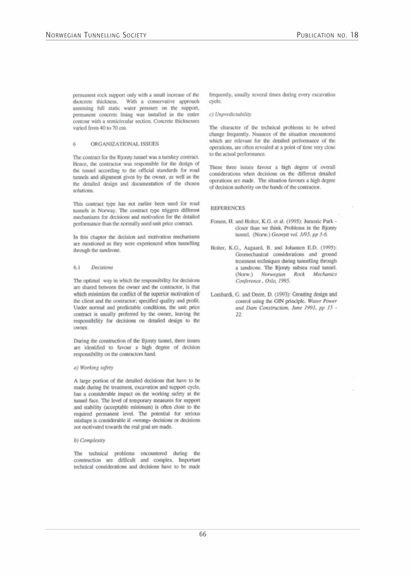
NorwegiaN TuNNelliNg SocieT y PublicaTioN No. 18
66

NorwegiaN TuNNelliNg SocieT y PublicaTioN No. 18
67
THE OSLOfJORd SUBSEA TUNNEL, A CASE RECORd
Arild Palmstrøm

NorwegiaN TuNNelliNg SocieT y PublicaTioN No. 18
68

NorwegiaN TuNNelliNg SocieT y PublicaTioN No. 18
69

NorwegiaN TuNNelliNg SocieT y PublicaTioN No. 18
70

NorwegiaN TuNNelliNg SocieT y PublicaTioN No. 18
71
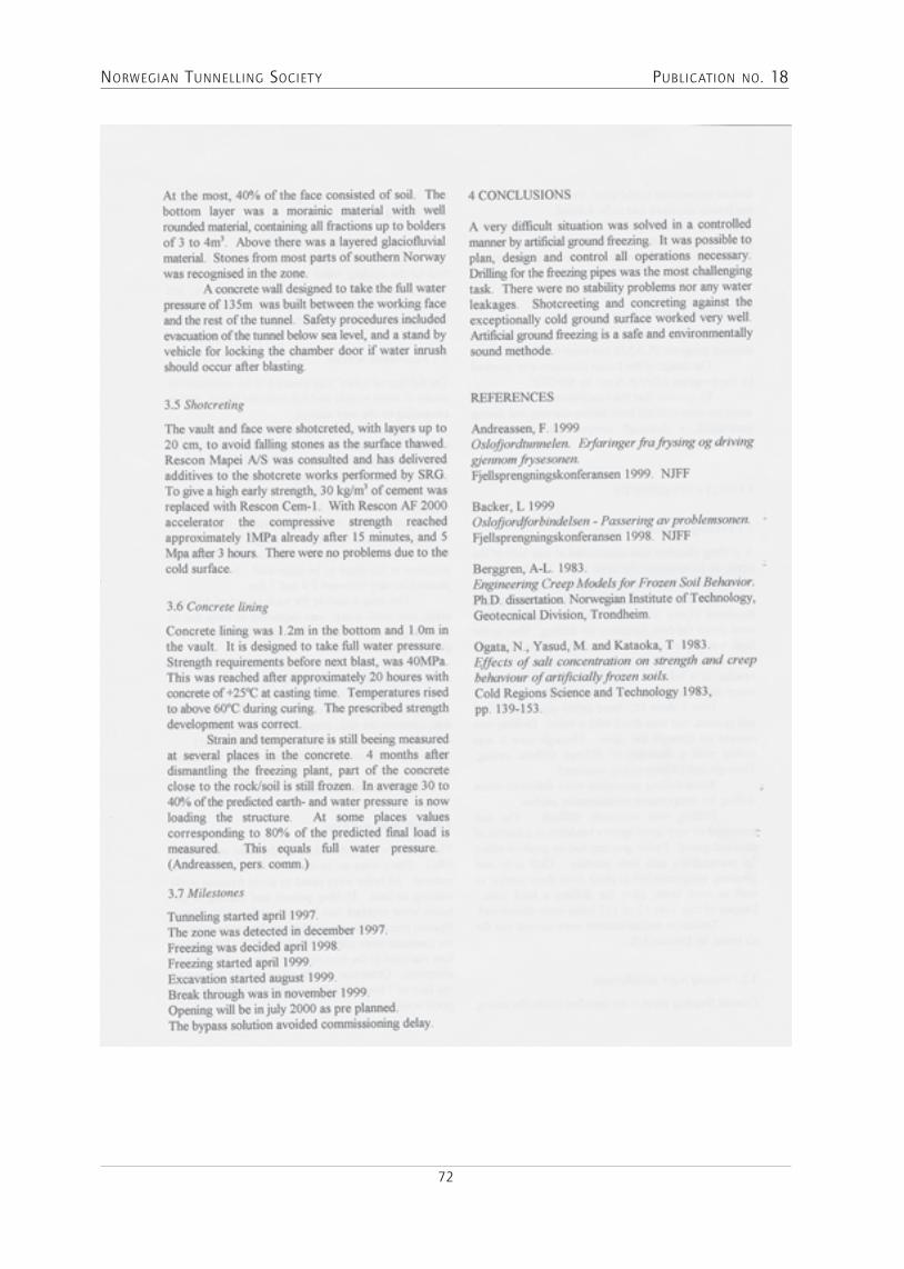
NorwegiaN TuNNelliNg SocieT y PublicaTioN No. 18
72

NorwegiaN TuNNelliNg SocieT y PublicaTioN No. 18
73
ARTICLE ABSTRACT: Underground projects today are often characterised by difficult ground condi-tions, complex contracts and environmental focus. For subsea tunnels in particular, the consequences of a tunnel collapse can be enormous. Quality control therefore is an essential part of such projects. Key factors for success are adequate geological investiga-tion and good planning of the tunnel work. In this paper some general aspects of new trends in geo-physical and geotechnical planning and control are described, as well as the investigation and planning of the 5.3 km long and 160 m deep Fröya sub-sea tunnel between two islands, Hitra and Fröya off the Tröndelag coast, in Norway. The area has been exposed to complex faulting, resulting in extreme tunnelling conditions. Special precautions, extensive investigations, and measures for quality control have therefore been taken to ensure completion of the project within time and at budget.
1. INTRODUCTIONThe Fröya sub-sea tunnel is presently under construc-tion on the north-west coast of Norway, see Figure 1.About 30 sub-sea rock tunnels have previ-ously been successfully completed along the coastline of Norway. Thus, valuable in-put from a number of comparable projects could be benefited from in the planning of the Fröya tunnel. When the Road Authori-ties still wanted this project to be thor-oughly evaluated, in fact by two independ-ent panels of experts, this was based on the anticipated very difficult ground condi-tions of the Fröya tunnel
The Fröya tunnel is the second sub-sea tunnel of the Hitra-Fröya project. The 5.7 km long and 264 m deep Hitra tunnel was completed in 1994. See Figure 2. The pre-investigations for both tunnels started in 1982, and for the Fröya tunnel it went on more or less con-tinuously until construction started in early February 1998. (Horvli - 1992, Heggstad and Nålsund - 1996). Compared to other, similar projects, very comprehen-sive investigations were carried out, revealing compli-
cated and, in some cases, rather uncertain geological condi-tions. Thus, very challenging tunnelling condi-tions were anticipated, with several large, and probably difficult, weakness zones to pass through, and in addi-tion, possibilities of encountering young, sedi-mentary rocks.
2. BACKGROUNDThe Fröya Tunnel is the final leg of the Hi-tra & Fröya Mainland Fixed Link. The project is completing a package allotted by the Ministry of Transport and Communications in order to replace ferries and improve ac-cess to the national road network and boost a flour-ishing local industry, mainly fish farming. The project stand up to com-petition to other projects in more rural ar-eas only when you factor in a public policy to provide
The Fröya Tunnel - GoinG subsea on The brink oF The ConTinenTal shelF
Kristin Hilde Holmöy, Engineering GeologistJon E. Lien, Project ManagerArild Palmström, Advisor
Figure 1. Location of the Fröya Tunnel where exception-ally poor rock conditions has been experienced.
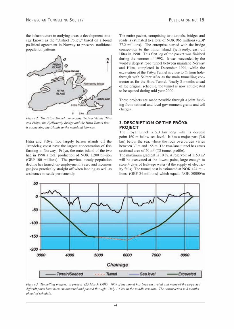
NorwegiaN TuNNelliNg SocieT y PublicaTioN No. 18
74
the infrastructure to outlying areas, a development strat-egy known as the “District Policy,” based on a broad po-litical agreement in Norway to preserve traditional population patterns.
Hitra and Fröya, two largely barren islands off the Tröndelag coast have the largest concentration of fish farming in Norway. Fröya, the outer island of the two had in 1998 a total production of NOK 1.200 bil-lion (GBP 100 millions). The previous steady population decline has turned, un-employment is zero and incomers get jobs practically straight off when landing as well as assistance to settle permanently.
The entire packet, comprising two tunnels, bridges and roads is estimated to a total of NOK 965 millions (GBP 77.2 millions). The enterprise started with the bridge connec-tion to the minor island Fjellvaeröy, east off Hitra in 1990. This first leg of the packet was finished during the summer of 1992. It was succeeded by the world’s deepest road tunnel between mainland Norway and Hitra, completed in December 1994, while the excavation of the Fröya Tunnel is close to ¾ from hole-through with Selmer ASA as the main tunnelling con-tractor as for the Hitra Tunnel. Nearly 8 months ahead of the original schedule, the tunnel is now antici-pated to be opened during mid year 2000.
These projects are made possible through a joint fund-ing from national and local gov-ernment grants and toll charges.
3. descrIptIon oF the Fröya projectThe Fröya tunnel is 5.3 km long with its deepest point 160 m below sea level. It has a major part (3.6 km) below the sea, where the rock overburden varies between 37 m and 155 m. The two-lane tunnel has cross sectional area of 50 m² (T8 tunnel profile).The maximum gradient is 10 %. A reservoir of 1150 m³ will be excavated at the lowest point, large enough to store 4 days of leak-age water (if the supply of electric-ity fails). The tunnel cost is estimated at NOK 424 mil-lions. (GBP 34 millions) which equals NOK 80000/m
Figure 2. The Fröya Tunnel, connecting the two islands Hitra and Fröya, the Fjellvaeröy Bridge and the Hitra Tunnel that is connecting the islands to the mainland Norway.
Figure 3. Tunnelling progress at present (25 March 1999). 70% of the tunnel has been excavated and many of the ex-pected difficult parts have been encountered and passed through. Only 1.6 km in the middle remains. The construction is 8 months ahead of schedule.

NorwegiaN TuNNelliNg SocieT y PublicaTioN No. 18
75
tunnel (GBP 6.400/m). The tunnelling works started in February 1998, with a planned hole-through in August 2000, and opening of the tunnel for traffic in June 2001. Only 1.6 km in the middle remains. The construction is 8 months ahead of schedule and the tunnel might be opened already summer 2000.
3.1 GeoloGyThe metamorphic rocks in the area are of Precambrian age with gradual transitions between various gneissic rocks, such as granitic gneiss, micagneiss, and migma-tite. A few bands or layers of limestone/marble have been observed in the actual area. The strike of the rocks is mainly ENE-WSW with steep dip towards NW. The area has been exposed to major fault-ing in Precambrian as well as the Caledonian and the Alpine Orogenesis. Several depressions and valleys represent-ing faults and thrusts can bee seen in the topography. Similarly, also the map of the sea bottom showed topog-raphy with marked depressions indicating the presence
of fault or other weakness zones. The refraction seismic measurements con-firmed this. A main geological feature is the Tarva fault (see Figure 4) which can be followed more than 150 km towards NW on the Norwe-gian mainland. This probably old fault is as-sumed reactivated during the Juras-sic/Cretaceous, maybe also in the Tertiary time.
3.2 FIeld InvestIGatIonsThe field investigations for the project started in 1982 with construction of maps, collection of available geo-logical material, and the initial seismic measurements, con-sisting of shallow reflection seismic (acous-tic) measurements and the first refraction seismic profiles. In 1995, during the final design, core drill-ings were per-formed from both sides of the Fröy Fjord. Unexpected, exceptionally poor ground conditions were then dis-covered in the northern side of the fjord. The tunnel alignment was adjusted to the East in this part, where
Figure 4. Assumed main weakness zones in the tunnel area, as interpreted from geological maps, aerial photos and field inves-tigations.
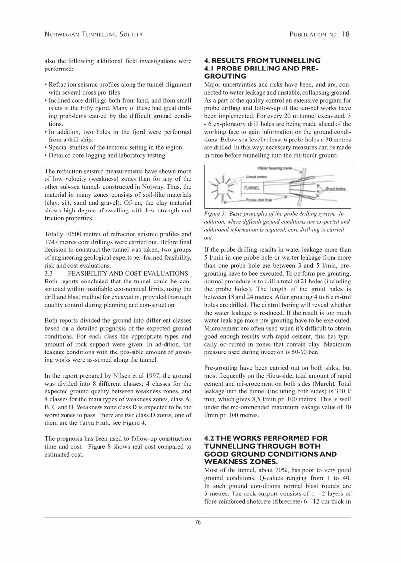
NorwegiaN TuNNelliNg SocieT y PublicaTioN No. 18
76
also the following additional field investigations were performed: • Refraction seismic profiles along the tunnel alignment
with several cross pro-files • Inclined core drillings both from land, and from small
islets in the Fröy Fjord. Many of these had great drill-ing prob-lems caused by the difficult ground condi-tions.
• In addition, two holes in the fjord were performed from a drill ship.
• Special studies of the tectonic setting in the region.• Detailed core logging and laboratory testing
The refraction seismic measurements have shown more of low velocity (weakness) zones than for any of the other sub-sea tunnels constructed in Norway. Thus, the material in many zones consists of soil-like materials (clay, silt, sand and gravel). Of-ten, the clay material shows high degree of swelling with low strength and friction properties.
Totally 10500 metres of refraction seismic profiles and 1747 metres core drillings were carried out. Before final decision to construct the tunnel was taken, two groups of engineering geological experts per-formed feasibility, risk and cost evaluations.3.3 FEASIBILITY AND COST EVALUATIONSBoth reports concluded that the tunnel could be con-structed within justifiable eco-nomical limits, using the drill and blast method for excavation, provided thorough quality control during planning and con-struction.
Both reports divided the ground into differ-ent classes based on a detailed prognosis of the expected ground conditions. For each class the appropriate types and amount of rock support were given. In ad-dition, the leakage conditions with the pos-sible amount of grout-ing works were as-sumed along the tunnel.
In the report prepared by Nilsen et al 1997, the ground was divided into 8 different classes; 4 classes for the expected ground quality between weakness zones, and 4 classes for the main types of weakness zones, class A, B, C and D. Weakness zone class D is expected to be the worst zones to pass. There are two class D zones, one of them are the Tarva Fault, see Figure 4.
The prognosis has been used to follow-up construction time and cost. Figure 8 shows real cost compared to estimated cost.
4. results From tunnellInG 4.1 probe drIllInG and pre-GroutInGMajor uncertainties and risks have been, and are, con-nected to water leakage and unstable, collapsing ground. As a part of the quality control an extensive program for probe drilling and follow-up of the tun-nel works have been implemented. For every 20 m tunnel excavated, 3 - 6 ex-ploratory drill holes are being made ahead of the working face to gain information on the ground condi-tions. Below sea level at least 6 probe holes a 30 metres are drilled. In this way, necessary measures can be made in time before tunnelling into the dif-ficult ground.
Figure 5. Basic principles of the probe drilling system. In addition, where difficult ground conditions are ex-pected and additional information is required, core drill-ing is carried out.
If the probe drilling results in water leakage more than 5 l/min in one probe hole or wa-ter leakage from more than one probe hole are between 3 and 5 l/min, pre-grouting have to bee executed. To perform pre-grouting, normal procedure is to drill a total of 21 holes (including the probe holes). The length of the grout holes is between 18 and 24 metres. After grouting 4 to 6 con-trol holes are drilled. The control boring will reveal whether the water leakage is re-duced. If the result is too much water leak-age more pre-grouting have to be exe-cuted. Microcement are often used when it’s difficult to obtain good enough results with rapid cement, this has typi-cally oc-curred in zones that contain clay. Maximum pressure used during injection is 50-60 bar.
Pre-grouting have been carried out on both sides, but most frequently on the Hitra-side, total amount of rapid cement and mi-crocement on both sides (March). Total leakage into the tunnel (including both sides) is 310 l/min, which gives 8,5 l/min pr. 100 metres. This is well under the rec-ommended maximum leakage value of 30 l/min pr. 100 metres.
4.2 the works perFormed For tunnellInG throuGh both Good Ground condItIons and weakness zones.Most of the tunnel, about 70%, has poor to very good ground conditions, Q-values ranging from 1 to 40. In such ground con-ditions normal blast rounds are 5 metres. The rock support consists of 1 - 2 layers of fibre reinforced shotcrete (fibrecrete) 6 - 12 cm thick in

NorwegiaN TuNNelliNg SocieT y PublicaTioN No. 18
77
roof and partly the walls, in conjunction with 3 m long CT-bolts (fully grouted).
In weakness zones more thorough meas-ures and rock support are necessary. In ad-dition to probe drilling and occasionally grouting, some of the measures in difficult ground are:
1) To stabilise the ground over and on both sides of the next round by 6 m long spil-ing bolts spaced 0.3 - 0.5 m.
2) To use short blasting rounds and spray-ing of fibrec-rete on roof, walls and face shortly after blasting.
3) To use stepwise excavation and concrete lining in addition to 2) where stability is very poor.
4) Concrete invert5) Availability of equipment to quickly and fully con-
crete the tunnel face, in case of dangerous situations, such as cave-in, progressive sliding, etc.
6) High pumping capacity and modern equipment for rock support operating at short notice.
To check the stability of the construction, convergence measurements are started some time after the zones are passed through. Usually the displacement ceases after a few months. But in one of the weakness zones the dis-placement was 17 mm, concrete invert were executed to sta-bilise the movements. Latest measure-ments show that the concrete invert has slowed down the displace-ment, see Figure 6.
4.3 example From the tunnellInG works In the tarva-Fault at chaInaGe 4435 - 4510The Tarva-fault is one of two class D weak-ness zones. The refraction seismic meas-urement show a 65 m wide zone with 3,0 km/s velocity. The rock overburden is minimum 40 m.
Probing by core drilling performed from a recess in the tunnel showed that the zone consisted of altered marble, marblebrec-cia/conglomerate, sandstone, calcite and pegmatite containing clay seams with thickness 5 cm to 4 m. In the midst of the fault there were several places with core loss of 0,5 to 1 m. Tests of the clay at chain-age 4444 showed swelling pressure of 0,7 MPa.
There was a sharp boundary between good rock condi-tions (gneiss) and the fault. The weakness zone started with a 4m wide zone consisting of mainly clay. There were no leakage and therefore no problem con-cerning the stability.
Probe drilling at chainage 4469 gave a wa-ter leakage of totally 59 l/min in 6 probe holes, grouting was necessary in the re-maining part of the weakness zone.
Approximately 100 tons of cement was in-jected in the Tarva-fault, 60 tons thereof were microcement. Poor ground conditions (soil-like material) combined with minor leakage resulted in less stabile conditions. The following steps were implemented in tunnelling through the zone:
Figure 6. Convergence measurement at chainage 7370

NorwegiaN TuNNelliNg SocieT y PublicaTioN No. 18
78
• reduced excavation round, only 3 m (in-stead of 5 m);
• 6 m long fully grouted spiling bolts with 0.2 - 0.4 m spacing (36 - 95 bolts per round). Steel straps and shotcrete are used to fix the outer end of the bolts to the rock;
• 1 - 2 layers of fibre reinforced shot-crete (fibrecrete) 6 - 12 cm thick in roof and walls, immediately after blast-ing;
• 3 m long CT-bolts (fully grouted), in average spaced 1.5 m; and
• additionally 2 - 3 layers of fibrecrete, total shotcrete thickness 12 - 31 cm.
• three reinforced ribs of sprayed con-crete• the floor along the zone was concreted (69 m) • concrete lining (64 m)
In the poorest ground quality, chainage 4476 - 4483, the excavation was carried out using the excavator.
4.4 comparIson oF estImates and encountered condItIons.The detailed assumption of expected ground conditions, rock support, and con-struction cost has been used to compare the real cost accumulated to the estimated cost for these operations. (Exchange rate NOK 100 = GBP 8). As shown in Figure 8, there is a very good accord-
ance between estimated and real cost for rock support and grouting. This is also the case for the southern (Hitra) part of the tunnel.
reFerencesHeggstad, S. and Nålsund, R. (1996): The Fröya tunnel - Challenging field investigations of a ground resembling soil. Fjellsprengningskonferansen (National tunnelling conference) 1996, 20 p.Nålsund R., Heggstad S., Mehlum A. and Aagaard B. (1996b): Analysis of excavation methods and rock sup-port. Internal project report, 21 p.Horvli, I. (1992): Geological and geophysical investiga-tions for the Hitra and Fröya sub-sea tunnels. Norwegian Soil and Rock Eng. Assoc., Pub. No. 8, p. 59-65.Lillevik S., Holmöy K. and Lien J. E. (1998): The Fröya tunnel - Passing through problematic zones - Experience from investigations and the conditions encountered (in Norwegian) Fjellsprengningskonferansen 1998, 22 p.Nilsen B., Palmström A. and Stille H. (1997): Analysis of excavation and rock support methods as basis for cost estimate, feasibility and risk assessments. Internal project report, 50 p.
Fig 7. Details of the zone at chainage 3975 – 4025

NORWEGIAN TUNNELLING SOCIET Y PUBLICATION NO. 18
79
SUMMARY The subsea-tunnel Atlanterhavstunnelen will replace the present ferry-connection between Kristiansund and Averøy in Møre and Romsdal county.
During the building of this tunnel a weakness zone in this subsea-tunnel collapsed 230 mbelow sea level. This collapse caused a substantial leak-age of seawater. The leakage reached a maximum of 500 litres pr minute in one 64 mm drilling-hole. The waterpressure sometimes reached 23 bar. The collapsed weakness-zone had to be plugged with concrete and it was necessary to do a comprehensive and time-consuming grouting before passing through the 40 metres wide fault-zone. The period from the moment the collapse occurred and until the fault-zone was passed lasted about 10 months and about 1000 tons of grouting was required.
INTRODUCTIONRv64 Atlantic Ocean Tunnel will link the municipalities of Averøy and Kristiansund in Møre and Romsdal. The
project includes about 3,9km of highway in Averøy, about 5,7km of undersea tunnel and about 0,6km of highway in Kristiansund.The project will be financed thus:Collection of toll fees 70,5%Municipal subsidies/loans 20,0%Alternative use of ferry subsidies 4,0%Highway Capital 5,5%Total 100%Cost estimates are 635million. 2005-Kr which is the equivalent of 700million 2008Kr. Johs.Syltern A/S are the main contractors for roads both in Averøy and Kristiansund. Mesta A/S are the main contractor on the undersea tunnel. The remainder of the address will deal with the undersea tunnel.
THE ATLANTIC OCEAN TUNNELThe Atlantic Ocean tunnel will be 5727m long and go down to 250m below sea level. From Averøy the tunnel slopes with a 10% gradient for about 2600m down to the lowest point. From the lowest point the gradient is about 6% for about 1200m before the last 1900m rises with a 10% gradient up towards Kristiansund. Parts of
RV64 ATLANTIC OCEAN TUNNEL LEAKAGE ZONE230M BELOW SEA LEVEL
Construction Manager Kåre Ingolf Karlson, Highways Directorate Midland Regio
Fig. 1 Perspective view of Rv64 Atlantic Ocean Tunnel

NorwegiaN TuNNelliNg SocieT y PublicaTioN No. 18
80
the tunnel with 10% gradient are blasted with profile T11,5, whilst parts with 6% gradient are blasted with profile T8,5.The tunnel is constructed with a gradual pumping out of leakage water. There were established 2 pumping stations in gradients on each side of the lowest point. In addition to the basin in the lowest point, there was established a smaller resevoir to collect and store leak-age water for a minimum 4 hours on the Averøy side and a minimum 24 hours on the Kristiansund side.
GeoloGyThe ground rock belongs to the Gneiss region of the Western region and consists in the main of gneissoid granite with elements of amphibolite, pegmatite and mica rich rock types. The gneissoid granite has tract direction ENE – WSW with moderate to steep drop which variates frequently. The most usual fissure for-mation direction is N – S with a steep drop. In addition there appears frequent fissures in the direction ENE – WSW, E – W and SE – NW – all with a moderate to steep drop.
Seismic investigations on this part of the tunnel which goes under the sea shows 13 weak-zones with a seismic velocity under 3500m/s. This constitutes about 3,5% of the length of the tunnel. Of these, 3 of the weak zones have a seismic velocity of 2500m/s. Seismic velocity between 3500m/s and 4500m/s are found in about 2,7% of the length of the tunnel. Otherwise the seismic velocity lies between 5000m/s and 6000m/s.
low velocIty zones 230m under sea levelAt the end of February 2008 there were blasted 2380m of tunnel at Averøy. The rock had given relatively little leakage problems and few grouting treatments were needed. Several of the weak-zones with seismic velocity in the area of 2800m/s – 3100m/s were surpassed with-
out any great challenges. This was probably because of regular and good overhead rock depths and little or no leakages in these zones.The last week of February 2008 we were confronted with seismic velocity 2800m/s and overhead rock depths down to 45m at about 230m under sea level. Above, the rock overhead depths were around 20m with estimated morainic material. A section of a geological engineering profile for the area is shown in fig.3.Tuesday 26th February there was carried out an extend-ed probe drilling with 6 holes in a length of 29m from profile 6229. The probing showed poor rock, but with little leakage. Data from the probe drilling gave no signal on any worse conditions than those that had been encountered in earlier weak- zones. It was decided to complete a grouting that would, in addition to filling this rock would also have a stabilising effect. The 6 probe holes were supplemented with a further 4 holes in a length of 26m such that the grouting screen in total covered 10 holes.
Fig.3 Section of geological engineering profile at the lowest point There were used 11,000kg of industrial cement in the screen.
Fig.2 Geological engineers profile.

NorwegiaN TuNNelliNg SocieT y PublicaTioN No. 18
81
The tunnel was blasted forward in relatively good rock until profile 6242 where the face stopped until Thursday 28th February. Two previous pulls were secured with concrete spray at night, whilst the last pull would be cleared on the morning of Thursday 28th February. Mesta reported early in the morning of poor rock with a small rock fallout on the face.This was secured with 24m3 sprayed concrete and radial bolts. It was also decided to move forward with an extended profile and reduced pull length Bolting with 16 x 6m long reinforced rod bolts at a distance of 50cm apart was completed before a 3m long pull was blasted. The rock was very poor with signs of rock fallout between bolts. There was about 20cm thick layer of spray concrete sat up around the profile and all the way down to the invert. Work on the laying of spray concrete was finished in the early hours of the night.
On the morning of Friday 29th February Mesta reported that the safety work carried out that night had begun to fall down. There was more spray concrete ordered, but the rock fall advanced so quickly that it became impos-sible to lay anymore. After a short consultation between contractors and developers it was decided that the face would be closed off with the tunnel waste stone in the overhead area and backwards to a secure area. The transport of the waste stone started at about 10am and by 19.30 the tunnel was plugged. There were used just over 2000m3. The last observation up in the rock fall area indicated that there had fallen 5 –6m overhang in the whole of the overhangs width and in the whole of the length of the pull of 3m, profile 6242 – 6245. In the course of the time it took to transport the stone in, the volume of water increased considerably. Later drilling of air and drainage holes indicated that the rock fall had spread to 10m of the overhang.
Fig.4 Drawing of the grouting screen carried out on profile 6229.
Fig.5 Drawing showing rock fall development
There were no signs of rock fall development behind profile 6242, but there was however laid extra sprayed concrete and fitted 5m long CT-bolts in a pattern of 2 x 2m. The bolts were grouted immediately. Sprayed con-crete was also used to seal the transition between the overhang/walls and heaps of stone.
Fig. 6 Drawing showing the sealing of the rock fall area with the tunnel waste stone and spray concrete.
After completion of the safety work there were drilled holes for and installed 100m of pipes to pump concrete mortar into the rock fall area over the stone screes. To allow for the possibility of evacuation of water and air in the rock fall area, there were drilled 64mm holes in the rock over the pump pipes. Preparations to start pumping on Saturday morning were complete. Initially it was attempted to pump in mor-tar with a maximum grain size of 22mm, but this failed. Afterwards the grain size was reduced to 16mm and this suc-ceeded. Initially there was pumped 130m3 but the pressure became too much. Inspection drilling revealed a cavity and a rock fall mass mixed in the concrete just 3,5 – 4m above the overhang. There were then drilled for and installed 2 new 100mm pipes and pumped in another 110m3 concrete.

NORWEGIAN TUNNELLING SOCIET Y PUBLICATION NO. 18
82
Fig. 7 There was pumped in a total of 240m3 into the rock fall area above the overhang.
Fig. 8 The pumping in of concrete into the rock fall area.
A hazard assessment jointly carried out by the contrac-tors and developers concluded that there should be a wall casted to ensure against possible large quantities of water under high pressure. A concrete wall would also function as a barrier to grout against. After some hard-ening time for the concrete in the rock fall area, heaps of stone were hauled up and cleared down to the tunnel invert. There were drilled and grouted 32mm reinforced steel over the whole of the breadth of the tunnel to secure the concrete. The concrete screen was transported up to the face on March 4th. On the morning of March 6th pumping of the concrete was started and on Saturday March 8th it was finished. A total of 1200m3.On Sunday 9th March it was reported that a leakage had washed out the concrete. There was installed a 110mm pipe for drainage and pumped in a further 20m3 of con-crete were pumped in.
Fig. 9 Concrete screen under construction for installation.
Fig. 10 Drawing of the concrete plug
On 11th March, after the screen was dismantled, drilling started to enable grouting through the concrete plug. It was drilled into the transition area between concrete and the screes of waste stone. In total 21 holes with a length of 6,5m to 16,5m.Contact with professor Bjørn Nilsen from NTNU was established on the 11th March for a review of the situ-ation. He was at the construction site on March 12th. Professoe Bjørn Nilsen had no objections to the meas-ures that were taken once the rock fall had actually happened. He realised that we had to prepare for core drilling through the rock fall zone and as long as the zones extent was established, he also gave his agreement on the planned grout work through the concrete plug.

NorwegiaN TuNNelliNg SocieT y PublicaTioN No. 18
83
Fig. 11 The concrete plug ready for drilling for grouting work.
Thursday 13th March the grouting through the concrete plug was finished. Grouting pressures were up to 80bar. 297 tons of industrial cement were used. After the clean up of equipment was completed it was the Easter holidays.After Easter, March 25th, drilling was started for grout-ing in the rock around the contours in front of the rock fall zone. There was drilled a 29m long hole with varying lak out such that an outer and inner screen were established. The whole of the screen around the profile consisted of 35 holes. In addition there were 12 holes drilled in the face through the concrete plug divided by 3 rows. These holes were drilled as far forward as was possible. Drilling revealed that not all of the stone screes were filled with grout. Drilling was stopped when the drilling water disappeared. The lowest row reached into profile 6234, the middle row to profile 6238, whilst the highest row reached to profile 6243. Drilling of holes around the contours and through the rock fall zone went relatively well. There was leakage in most of the holes. They were grouted with pressure up to 100bar and 93 tons of industrial cement were used. After hardening overnight, there were drilled 2 inspection holes in the overhang up to about 6245, both holes were dry. From the 28th March work began on blasting away the concrete plug. This was time consuming because of high heat in the concrete plug and a reaction to ammonia gas development between blasting material and concrete. There were measured up to 60 degrees in the drill holes. Mesta had close contact with Orica Mining in connection with blasting and gas development in the concrete plug.The length of the pull varied between 3 and 5 m in to profile 6237. In the process of penetration of the concrete plug there were probe drillings from the profile 6228 and in to 6250, and from profile 6231 and in to 6250.Nearly all of them were almost dry. There were some problems with the drilling through the rock fall zone, but between profile 6245 and 6250 the impression was given of a better quality of rock.
Fig. 12 The concrete plug ready for drilling for grouting work.
From profile 6237 it was bolted with 28 x 12m long Ischebeck stay bolts and 12 x 12m long 32mm rein-forced steel bolts through the concrete in the rock fall zone over the overhang to secure that the onncrete plug would be kept in place when it was blasted.
After 3m pull towards profile 6240, it was bolted with 16 x 12m long Ischebeck stay bolts, 24 x 12m long 32mm reinforced steel and 34 x 8m long 32mm reinforced steel bolts. The distance between the bolts was about 30cm. The pulls from the profile 6230 and forwards was a combination of blasting and machine scaling The grouted stone screes held up well, but were easy to the machine scaling, see fig.14.On April 8th, approximately 5,5 weeks after the collapse, the tunnelling had continued forward to the edge of the rock fall zone, profile 6242. This pull was divided into 2 , where the uppermost part of the face was blasted first and secured with spray concrete and CT bolts before the bottom part of the face was blasted and secured.Fig. 13 Principle bolting through the rock fall zone. Approximate pull length through the affected area.
The following day, April 9th, the uppermost part of the face was blasted in to profile 6243,5, cleared and secured with sprayed concrete. Bolting with 32mm reinforced steel in lengths of 8m mounted over and underneath. The 10th April the lower part of the face was blasted in to the same profile, before the bolting was mounted in the walls. The face was secured with sprayed concrete and it was prepared for core drilling.

NorwegiaN TuNNelliNg SocieT y PublicaTioN No. 18
84
Core drilling started late on Friday evening and was stopped early on Monday the 14th April. By then the core drilling rig was almost inundated by water. The reason for this was the leakages from the core drill holes of well over 300litres pr.min. combined with the poor effect of the pumps. The core drill holes were stopped after 27,2m, that is near the profile 6270. The drilling rig could not rotate the drill string because the water brought so much crushed stone into the middle of the
drill hole. The leakages in the core drill hole started at about 12m, but increased strongly on the last few metres. The rock quality was poor in the whole drill holes length, but at a section in the middle of the hole it was somewhat better.In consultation with the Directorate of Roads it was decided to establish a panel of experts to help them get through the strong water flowing weak zones. Professor Bjørn Nilsen from NTNU was already called in as a consulent and was asked to lead the panel. In addition, civil engineer Bent Aargaard, Sweco Norge, Doctor of Engineering Steinar Roald, company owner and geo-logical engineer Knut Borge Pedersen, The Directorate of Roads were also engaged. The construction leader on the Averøy face, Tormod Magne Steine, Mesta and the undersigned were also included in the expert panel. Untill the panel of experts could start work, it was agreed with Bjørn Nilsen that the face be reinforced further with spray concrete to a thickness of about 25cm before it was bolted systematically 2,5m and installed with rock belts in a scissor pattern. There was installed a pipe in the core drilling holes before spray concrete was laid such that the water could run through to pre-vent a build up of pressure. Before work could continue forward from the face profile 6243,5, the tunnel was secured with full grouting from profile 6238 to profile 6242. The bolting which was put in from profile 6243,5 protruded so far out that they penetrated into the grout-
Fig. 14 Grouted screes of tunnel stone.
Fig. 15 Cores from 14 – 21 m (profile 6257,5 – 6264,5)
Fig. 16 Cores from 21 – 27,2 m (profile 6264,5 – 6270,7)
fig. 13. Ischebeck stay bolts were used where it was difficult to insert reinforced steel bolts.

NorwegiaN TuNNelliNg SocieT y PublicaTioN No. 18
85
ing. Grouting was completed and the shield transported from the face on April 25th.The panel of experts had its first meeting on April 23rd.
the panel recommended:• At least 10m of compact rock in front of the face.• The grouting screen should reach 7m outside the
tunnel contours. • Grouting pressure max. 50 bar • Micro cement • The face moves forward by taking out the uppermost
section which is secured before the lower section is blasted as described earlier.
• Maximum pull length 2m.• Bolting of 30cm for every 2m.• Securing with reinforced spray concrete arches of
1,0m • Establishment of a systematic inspection of the tunnel
contours with a extensometer measurement as close up to the face as is practically possible.
• Grouting pressures and the types of grouting materials were discussed at great lengths.
After the concrete shield was transported from the face, there were drilled 16 x 6m long probe holes through the last section of the partly grouted stone screes and further in towards the weak zone. Because of the stone screes, it was impossible to plug the hole. It was therefore decided to move the face forward in to profile 6245 where it was when the rock fall happened. After blasting of the uppermost section there came down some rock fall mass in small portions between the bolts. This made spray concreting work difficult, but it was ulti-mately finished. It took 8,5 weeks to work the tunnel forward in to where it was before the rock fall happened. Reinforced sprayed concrete arches were mounted at profile 6243.The face at about profile 6245 showed the most signs of rock fall mass. Short probe holes 8 –9m, indicated a lit-tle better situation from profile 6247. Probe holes gave leakages from 1,0 – 18,0litres pr. min.. from 5 – 8m in from the face. The face was worked forward into this by the same formula used earlier. ”The rock” is taken out partly by blasting and partly by machine scaling/digging. There are established new reinforced spray concrete arches.
The 6th May saw the start of drilling on a 8m long grout-ing screen to press the water forward and out of the face. This proved to be the start of a long battle against out-lets in the face and in the invert and overhang/bolt holes behind the face. It was deemed necessary to have 90 – 100 holes in every screen, but this variated according to which results were gained. In the main, micro cement
was used, but controlled hardening, clogging material and polyurethane foam were also used to control outlets. After every completed screen, the screen length was increased by 3m. To ease installation of packers and reduce outlets of grouting mass on the face, there was in some of the holes fixed in 5m long pipes. This clearly had its advantages, but the pipe was smooth and the packings came more easily out than they held in the rock. Where the pipes were installed, they were used in several grouting rounds by drilling new and deeper holes along the same pipes. After a while it was also attempted to fix in grouting rods as anchorage. This gave good results where there was no significant leak-age in the screen holes.The 13th June the leakages were pressed to 16 – 18m in front of the face. The face could then be worked for-wards in 2m sections as described earlier, up to profile 6253.After many new rounds of grouting with variable results, the tunnel could be blasted up to profile 6258 where it has been since the 12th of September.It was shown by the first grouting screen that the spread-ing of grouting mass was apparently small. The drilling inspection holes near to the grouted holes could give leakages further out than the drilled length of the grout-ing hole and there was in most of the screens little effect further in than the grouting hole was drilled. An example of this grouting of the screen with 14m long poles from profile 6258. In total there were 152 grouting rounds around the contours and in the face of the screen. There were pumped in just over 153 tons of grouting mass. The impression was, after the grouting were com-pleted that it was a successful screen. Upon drilling of the next screen from the same location, profile 6258, with a hole length of 17m, the drill rods locate cavi-ties without drill resistance about 12m in which leads to great quantities of water. This happens in 2 adjacent holes. When 17m of the screen is completed and it is drilled for a 20m long screen, it is met with water in parts even further out than the 12m from the face.It was also quickly recognised that to have pre drilled holes in every grouting round was favourable. This was favourable both with consideration to inspection of leakages and to reduce outlets on the face. After every forward movement of the face to a new location for grout-ing, it was strengthened with 0,5m spray concrete and systematic bolting undertaken combined with rock belts in a scissor pattern. It was nonetheless a problem that the spray concrete cracked because of the grouting pressure on the transition of rock/spray concrete instead of press-ing the grouting mass out through the fissures in the rock. Spray concrete was necessary for safety, but it made it dif-ficult to get a view over where outlets and water leakages came out of the face. Because of the cracking, the face was cleared of spray concrete and secured many times. There measured leakages of up to 500litres per. min. from a drill hole and measured pressure up to 23 bar.

NorwegiaN TuNNelliNg SocieT y PublicaTioN No. 18
86
Grouting pressure was eventually increased to 70 bar when the water was pressed about 15m in front of the face in the central area of the zone with somewhat bet-ter rock quality. This resulted in better communication between grouting holes and better results from every grouting screen.Whilst the Averøy face has almost stood still, there has been good progress on the Kristiansund face. The Kristiansund face has also exceeded low velocity zones with seismic velocity down in 2500m/s. The rock how-ever has been compact and the zones have been driven through without any great problems.It was always the plan that core drilling from the Averøy face would survey how far the zone extended but we were dependant on getting leakages under control first. When the Kristiansund face had arrived at profile 6315, then the core drilling would be carried out from Kristiansund. Before the core drilling started , it was decided to drill into profile 6280 if possible. The first core drill hole was drilled into the right side of profile 6280 without reaching the zone boundaries. There were also small leakages. There was then drilled a core drill hole on the left side. Before starting it was decided that this hole would be drilled in to profile 6275. In this core drill hole lay the zone boundary of profile 6283,5 and a leakage in the bottom of the hole, profile 6275, was 160litres pr.min. After the core drilling it was decided to begin a systematic grouting for every 5m with 20m long screens.The situation per 2nd November is that the Averøy face is at profile 6258 and grouted with 20m long holes into the area profile 6278. The Kristiansund face is at profile 6305 and is com-pletely grouted to profile 6285. The distances between the faces is about 47m. After the Kristiansund face is blasted to profile 6300, it will not be blasted any further before the zone is closed up. Almost 9 months after the rock fall, the Averøy face has advanced 13m and used almost 1000 tons of grouting mass. We must expect that much of the tenth month will also og over before there will be a breakthrough.
I have covered little about the findings of the panel of experts. This does not mean that they have not been use-ful. The guidelines which were laid down by the panel at the start, have been present through the whole work. The panel has supported and given new initiative when dejection has threatened to take over. So far the panel has had 11 meetings in addition to contact by telephone and e-mail.To conclude it should be emphasised both the contrac-tors employees and the developers inspection engineers for an excellent contribution and their determination. There has been shown a level of patience far surpassing that which could have been expected.The last pull was blasted the 19. March.2009 at 1300 hours.
Fig.18 Drawings of the zone after core drilling from Kristiansund.
Fig.17 Grouting
NorwegiaN TuNNelliNg SocieT y PublicaTioN No. 18
87
IntroductIonOver the last 25 years 25 subsea tunnels have been com-pleted in Norway. As a result of an unforeseen incident that took place in the Oslofjord tunnel in August 2003 a programme for inspection of all subsea tunnels in Norway was initiated. The main purpose of the inspec-tions is to safeguard that signals from dewatering pumps are safely sent to the Public Roads Administrations control centres. Additionally all other safety equipment in the tunnels was checked. A work procedure for the planning of the inspection and how the inspection itself should be done for each tunnel was established.
pumps and alarmsIn the light of the incident with the pumping equipment in the Oslofjord tunnel in August 2003, one of the areas it was important to examine during the inspection was the control and monitoring of the pumps. Interest lay in particular in seeing which pump conditions and level conditions trigger alarms, how alarms are transmitted and how they are received at a manned control centre.
The inspected tunnels have an age spread of about 20 years and in addition are characterised by having a different basis for project planning and equipment selection. The differences found between the different tunnels related to elements including alarm texts at road traffic control centres, forced operation of the pumps at critical high and critical low levels, utilisation of all pumping power at high or critical high levels, critical low alarms and monitoring of internal and external com-munication.
No logic block for critical high alarms at lower levels in the sump was found, but in some cases where a critical high alarm was not transmitted as it should be, it was difficult to establish whether this was due to a logic block or whether the alarm is generated in control apparatus on the basis of the actual level in the sump. Still, this uncertainty serves to highlight the need for frequent visual inspections until these matters have been clarified.
There was found to be a substantial variation in the spare capacity of the reservoirs, ranging from a few hours to two weeks or more. The pumping capacity in relation to leakage also varies greatly from the case where all pumping power has to be used in the event of heavy rainfall to tunnels equipped with three pumps where only one is in operation at a time.
In all the tunnels, bar one, the alarms from the pumps are an integral part of the monitoring and control sys-tem. The safety level of the alarm path from level sensor to monitoring centre varies considerably in older equip-ment. In some places there is absolutely no guarantee of receiving a warning of faults in control apparatus or in the communication internally in the tunnel or externally between the tunnel and the road traffic control centre.The alarm texts at road traffic control centres for the critical alarms vary depending on which tunnel they come from. This is highly inadvisable, and the texts should be made the same for the whole country, or at least for each region.
InspectIon routInesThe inspection routines are agreed in the contract entered with the contractor. In many cases the electrics are dealt with separately and are covered by a separate subcontract with an electrical contractor, or they may be included in the functional contracts or in the transitional agreements with the maintenance contractor.
In two cases the Norwegian Public Roads Administration (NPRA) itself is responsible for checking the techni-cal installations and safety equipment. NPRA has a separate system for MOM (Management, Operation, and Maintenance) and internal checks of the tunnels, PLANIA (or SPEKTRUM as it was known before). This system is only in limited use, but where it is in opera-tion, methodology and documentation are in place.
Before the reorganisation of NPRA, it was for the most part the Production Division that used SPEKTRUM. They drew up check routines, conducted checks and
fINdINGS fROM AN INSPECTION Of THE SUBSEA ROAd TUNNELS
Asbjørn Martinussen

NorwegiaN TuNNelliNg SocieT y PublicaTioN No. 18
88
documented their findings. Much of the old way of working still seems to prevail in some places, especially where there are transitional agreements with the main-tenance contractor.
Although checks are carried out in different ways and are documented differently, they always focus on the most important factors. However, the documentation may seem rather incomplete and unsystematic.
It is recommended that PLANIA be used in all tunnels.
emerGency telephones and FIre extInGuIshersAll the tunnels we inspected are equipped with emer-gency telephones and fire extinguishers.The emergency telephones are mounted in SOS cabinets or in telephone booths. The telephones were tested (ran-dom tests) in all the tunnels; all of them worked.In some tunnels, the telephones are equipped with self-testing capability, which is a good solution. There was some variation in the alarms that are tripped when SOS cabinets are opened or when fire extinguishers are removed, and in the responses triggered. This should be standardised. Routines for closing the tunnel and call-out of emergency services vary quite considerably, and local agreements have been made with the police and fire service. This may be sensible on account of local conditions and is in accordance with the proposal NPRA has for emergency response planning.The sound quality of all the telephones we tested was satisfactory, with the exception of two.In general, it is difficult to hear the duty operator where the telephones are mounted in SOS cabinets and there is background noise from traffic and fans. The telephone booths which allow the user to go behind a closed door are a much more effective solution for shielding against background noise than the SOS cabinets, and it is recommended that they be used when upgrading older tunnels.
emerGency response plansEmergency response plans have been drawn up for all the tunnels and a fire protection manager appointed. The emergency response plans have principally the same format and have become a fairly comprehensive document.A separate crisis management plan for technical inci-dents has not been prepared for all tunnels. For about one third of the tunnels, a little information about cri-sis management has been included in the emergency response plan.No-one has drawn up written detailed plans for larger incidents, for example, lengthy and extensive power cuts, where the public road authorities must share avail-able resources with others.Back-up generators are found in a number of tunnels, and back-up pumps are quite common. Strategic parts other than these are only stored to a limited extent.
health, saFety and the envIronment (hse)The NPRA Handbook 213, relating to HSE when work-ing in road tunnels carrying traffic, appears to be well known.The setting out of warning signs for work in tunnels seems to be a problem area and a hazard factor. By the pump stations, at the bottom of the tunnel, it is always possible to pull into the side, but in the vicinity of other installations such as transformers and so on, it is often impossible to park a car off the carriageway.In the pump station we find several potential danger areas:• Live cables on the ground and electrical cabinets• Pump sump containing water, with large fall height
from the pump floor• Possibility of gas concentration in the sump, which
constitutes the lowest point of the tunnel.On the wholes cables have been laid safely, but we have seen examples of poor and slipshod workmanship.The HSE conditions vary a good deal. Some stations have no life-buoys and ladders are without fall protec-tion.

NorwegiaN TuNNelliNg SocieT y PublicaTioN No. 18
89
Corrosion is a general problem in subsea tunnels and there are instances of safety equipment that is heavily corroded. Ventilation of the pumping station and pump sump has not been the focus of much attention. CO is heavier than air and will tend to collect at the bottom. There were only a few instances of portable CO gauges being used in the sump. The use of such gauges should be compulsory.
other FactorsMost subsea tunnels are basically built according to the same concept. Nevertheless, we find a great variation in
the details of solution choices, of which some are good and some are less good. We have also noticed that at the end of the building period cuts in tunnel equipment have been made for budgetary reasons. The operating organisation has to cope with the result of these cuts for a long time afterwards.Corrosion is a general problem, and requires care and knowledge in the selection of materials. Unfortunately we see a great deal of corrosion of some components, also those that are vital.In the tunnels there is a lot of dust which penetrates eve-rywhere. Doors of high airtightness class and ventilation fitted with dust filters have limited effect. Dust and salt water evaporation can cause short circuits in the electri-cal installations, and necessitate thorough cleaning in cabinets and other structures.In two tunnels it was only possible to switch to the stand-by power generator at the bottom of the tunnel. This is an extremely poor solution.Pump stations are built as a cross-cut at a right angle from the tunnel. They are separated from the traffic area by fencing and a gate, or by a continuous wall with built-in gate and door. The introduction of access con-trol should be considered.

NorwegiaN TuNNelliNg SocieT y PublicaTioN No. 18
90
LNS - the mining- and tunnel contractor from the arctic
Telephone: +47 76 11 57 00 Email: fi [email protected] Web: www.lns.no
Leonhard Nilsen & Sønner AS (LNS) was established in 1961, and the LNS-group consistsof a total 15 companies. In 2008 the turnover was approx. NOK 2 billion (USD 304 million). The group’s number of employees is about 800. LNS main products are:• Tunnels, caverns• Mining contracts• Rock support, grouting• Earth moving• Ready mixed concrete plant• Production of modules and elements in wood
In 2008 LNS had the largest excavated underground volume by any Norwegian contractor.The last years LNS also has been engaged in Spitsbergen, all over Norway, Iceland, Russia,Greenland and the Antarctic. LNS has recently completed tunnelprojects in Lofast andFjøsdalen in Lofoten, Svalbard Global Seed Vault in Spitzbergen, road and accesstunnel toopening a new graphite mine in Senja, PPP E18 Kristiansand – Grimstad, 7 two-tubes tunnels of a new 4-lane motorway. Total length is 12 km and two tunnels on the new highway E18 Tønsberg. Some of LNS projects at the moment:• Mining operations, Spitzbergen• Mining operations for Elkem Tana, quartzite mine• Mining operations for Fransefoss in Ballangen, limestone mine• Ore handling, Narvik• SILA, Narvik new harbor• Salten Road Project, new two-lane road and tunnel, Røvik - Strømsnes• Project of securing road and tunnel, Lian in Grytøya• Transfer tunnel, 7 km, Kvænangen Hydro Power Project• Construction of a new main level for Rana Gruber AS iron ore mine• New dobbel track, Barkåker - Tønsberg, modernisation of the Vestfold line
vizuelli.no

NorwegiaN TuNNelliNg SocieT y PublicaTioN No. 18
91
backGround and motIvatIonOver the last years a number of road tunnels in Norway have experienced serious collapses of the tunnel roof due to failures of the surrounding rocks. One of the best known incidents happened on December 25, 2006 at Hanekleiv tunnel in Vestfold county when a roof segment collapsed. The 200 cubic meters of debris blocked a 25 m long stretch of the road and lead to the tunnel’s closure for more than 6 months. Apart from the direct risk rock falls pose to road users which might get harmed, these incidents lead to large economic losses when a tunnel has to be closed for repair or reconstruc-tion (Dagens Næringsliv, 2007).
In general, tunnels are complex three-dimensional struc-tures which are often characterized by heterogeneous rock materials that include faults and weakness zones, rapidly varying hydrogeological conditions, and other local disturbances of the rock body. When a new tunnel is constructed and opened for traffic it is automatically assumed by the users that the tunnel’s roof integrity is sound. However, over the years small cracks may open up with ground water penetrating, and hence the roof may gradually approach a state of collapse when large blocks loosen. The observation of these processes based on what may become visible at the rock surface is complicated since modern tunnels in Norway are mostly provided with an inner lining which prevents an easy inspection of the rock surface. In addition, the rock itself is mostly furnished with a layer of steel fiber-reinforced shotcrete immediately after drilling or blasting in order to safeguard the construction works and to prevent smaller rocks of falling down.
According to Norwegian road authorities (Statens vegvesen), the most common procedure for checking the tunnel roof condition today is through visual inspec-tion. This is a time-consuming, expensive, dangerous and to some extent also an unreliable process where inspectors crawl between the lining and the tunnel roof in order to identify visible changes or peculiarities at the surface. Recently, the first attempts were initiated by Statens Vegvesen to develop camera-equipped robotic
vehicles which are able to survey those parts behind the lining where the narrowness between rock and lining does not allow a manual inspection (Statens vegvesen, 2007).
technIcal approach towards tunnel health monItorInG (theam™)The current situation with regard to possibilities for tunnel monitoring in Norway and also worldwide calls for the development of alternative procedures. In recent years geophysical investigations have been applied suc-cessfully during tunnel excavation works in order to do predictions ahead of the tunnel face (Inazaki et al., 1999; Petronio et al., 2007; Lüth et al., 2008). This is especially conducted to foresee fault zones or danger-ous voids in the tunnel track to prevent construction downtime and to improve safety during the construction phase.
The presented approach on Tunnel Health Monitoring (THEAMTM) combines applied geophysical analysis methods with available technologies coming from sur-face seismics and geotechnical engineering with the objective to conduct a long-term structural safety moni-toring of existing rock tunnels.
Road or railway tunnels in general are traffic arteries which provide a number of unfavorable boundary con-ditions for the conduct of any inspection or monitoring measure. We suggest that a suitable procedure to moni-tor the integrity of existing tunnel structures should be:• non-invasive (any harm or damage to the existing
structure should be avoided),• cost-effective and easy to accomplish,• quick, so that road traffic is not disturbed or inter-
rupted,• robust, with regard to the hardware’s resistance against
humidity and dust exposure.Considering these constraints, the monitoring procedure THEAMTM was developed which uses changes in the seismic response of the rock material to a predefined
ThEAM™ – TUNNEL HEALTH MONITORING USING ACTIvE SEISMICS
Dominik H. Lang, Conrad D. Lindholm, NORSAR, P.O.Box 53, 2027 Kjeller, NorwayUlrich Polom, LIAG, Leibniz Institute for Applied Geophysics, 30655 Hannover, Germany
LNS - the mining- and tunnel contractor from the arctic
Telephone: +47 76 11 57 00 Email: fi [email protected] Web: www.lns.no
Leonhard Nilsen & Sønner AS (LNS) was established in 1961, and the LNS-group consistsof a total 15 companies. In 2008 the turnover was approx. NOK 2 billion (USD 304 million). The group’s number of employees is about 800. LNS main products are:• Tunnels, caverns• Mining contracts• Rock support, grouting• Earth moving• Ready mixed concrete plant• Production of modules and elements in wood
In 2008 LNS had the largest excavated underground volume by any Norwegian contractor.The last years LNS also has been engaged in Spitsbergen, all over Norway, Iceland, Russia,Greenland and the Antarctic. LNS has recently completed tunnelprojects in Lofast andFjøsdalen in Lofoten, Svalbard Global Seed Vault in Spitzbergen, road and accesstunnel toopening a new graphite mine in Senja, PPP E18 Kristiansand – Grimstad, 7 two-tubes tunnels of a new 4-lane motorway. Total length is 12 km and two tunnels on the new highway E18 Tønsberg. Some of LNS projects at the moment:• Mining operations, Spitzbergen• Mining operations for Elkem Tana, quartzite mine• Mining operations for Fransefoss in Ballangen, limestone mine• Ore handling, Narvik• SILA, Narvik new harbor• Salten Road Project, new two-lane road and tunnel, Røvik - Strømsnes• Project of securing road and tunnel, Lian in Grytøya• Transfer tunnel, 7 km, Kvænangen Hydro Power Project• Construction of a new main level for Rana Gruber AS iron ore mine• New dobbel track, Barkåker - Tønsberg, modernisation of the Vestfold line
vizuelli.no

NorwegiaN TuNNelliNg SocieT y PublicaTioN No. 18
92
excitation signal as an indicator for changes, i.e. crack-ing of the rock material near the tunnel surface. The procedure’s main task is to identify emerging cracks in the rocks in a non-invasive way before any hazardous collapses of the rock material occur. The main idea of the methodology basically is to excite the tunnel by well-defined, artificially generated seismic source signals and to record the response of the tunnel-bedrock-system at fixed receiver locations attached to the tunnel surface (Figure 1). The receivers can be either distributed at equidistant locations over the tunnel wall and roof surface or concentrated to those tunnel seg-ments where weak rock materials previously have been identified (weakness zones) and the generation of cracks is likely to occur.By repeating these experiments at regular time intervals (e.g. weekly, monthly, quarterly) and by correlating the seismic waveforms of the same sensor site over time, those tunnel parts can be identified where the seismic response and thus the integrity characteristics have changed over time. Assuming that all constraints and boundary conditions (e.g. technical equipment) remain unchanged, variations in the waveform characteris-tics over time can be allocated to changes in the rock integrity. This facilitates a more precise and targeted visual inspection of the rock materials in the vicinity of
the concerned sensor sites and hence a more thorough investigation of the causes.
In order to allow the long-term monitoring of large tunnel segments while meeting the defined prerequi-sites, the THEAMTM methodology as described above requires three main characteristics which will be succes-sively addressed in more detail:1. Penetration depth/length of the generated seismic
signals2. Reproducibility of the generated seismic signals3. Sensitivity towards mechanical changes in the rock
medium.
These characteristics call for actively generated seismic signals which are fully predictable both in amplitude and phase, highly reproducible, and of controlled total energy. Such well-defined signals are commonly in use during state-of-the-art land seismic exploration utilizing so-called Vibroseis methods (Crawford et al., 1960). The third characteristic calls for seismic signals sensi-tive to cracks or other changes in the mechanical behav-ior of the rock matrix irrespective of variations in the pore filling. Since shear waves fulfill this prerequisite, shear-wave generators (shaker, exciter) of different type come into operation .
Figure 1. Sketch illustrating the operation principle of THEAMTM. The electrodynamic shaker attached to the rock surface generates a deterministic sweep over a certain frequency range. The generated seismic signals are recorded on an array of geo-phones.

NorwegiaN TuNNelliNg SocieT y PublicaTioN No. 18
93
However, in order to develop a cost-effective procedure which can be applied over several years, the system must allow a fully automated mode that can run unat-tended and be operated by remote control.
penetratIon depth/lenGthThe determining factor for the procedure’s practical application and to achieve a good cost-benefit relation consists in the penetration length of the generated seis-mic signals. This means, that the applied shaker must be able to introduce a certain amount of energy into the rocks so that seismic waves of a certain amplitude and frequency travel over a long distance through the rock medium.
How far the excited shear waves penetrate i.e. travel through the rocks is, of course, dependent on a number of factors such as frequency and amplitude (i.e. the force with which the frequency is introduced into the rock) of the seismic signals, shear-wave velocity, damp-ing (elastic and inelastic) and geological integrity of the rock medium and the level of background noise. The latter is especially important with regard to the system’s application while the (road) tunnel is in use. However, experimental tests conducted under different noise lev-els reveal that higher levels of background noise can be easily tackled by the application of stacking techniques. Correlated time series between the artificially generated shear-wave signal and the response of the tunnel mate-rials at different distances to the source are illustrated in Figure 2. A suitable resolution of the signals at high frequencies can be observed at 100 m distance to the source. This clearly allows for an efficient investiga-tion of larger tunnel segments at once especially when placing the source site in the center point of a segment to observe.
Figure 2. Correlated time series between the generated source signals and the receiver response at different dis-tances (top: 5 to 38 m, bottom: 50 to 100 m). All receiver are placed along a line at the same tunnel wall as the shaker is mounted. The illustrated direction of motion complies with the direction of shaking. Note the different amplitude scaling between the two figures.
reproducIbIlIty A major prerequisite of the THEAMTM procedure consists in the ability to generate seismic signals which are fully reproducible over time both in phase and amplitude. This requires a high fidelity electronic con-trol of the source which at best is coupled with a sweep generator.
Figures 3 and 4 shows example results at two receiver sites which clearly demonstrate the system’s capability to produce identical signals over time. While Figure
Figure 3. Correlated recordings of 10 subsequent sweeps at receiver R20 (20 m distance, tunnel wall). The reproducibility of the seismic signals for subsequently conducted tests is a prerequisite for further investigations.

NorwegiaN TuNNelliNg SocieT y PublicaTioN No. 18
94
3 compares the correlated time series of ten consecu-tively conducted records within a 20 minute time frame, Figure 4 illustrates the stacked records at four different days over a one month period.
In order to accomplish reproducible signals, the mount-ing conditions of the shaker and the receivers (sensors) must remain unchanged. Investigations have proven that the slightest change of any of these conditions will
result in different results both in terms of amplitude and phase.
An important feature consists in the fact that the seismic signals are reproducible in all components of motion irrespective of the direction of excitation as well as at all locations on the tunnel surface irrespective of the mounting site of the shaker. As Figure 4 clearly dem-onstrates, reproducible signals can be achieved even at
Figure 4. Stacked correlated signals of several testings conducted over a month period at receiver D38 (38 m distance, tunnel deck). Both, shaker and receiver have remained in place during the testing period.
Figure 5. Correlated signals of several measurements which had been recorded over a two day period before and after changes had been applied to the immediate surroundings of receiver R5. After the first two recordings (before changes), changes were applied to the rock conditions at receiver R5 by drilling four holes of 12 mm diameter and 350 mm depth. Records conducted after the changes demonstrate a clear phase shift which can not be observed in the records at sensor D5.

NorwegiaN TuNNelliNg SocieT y PublicaTioN No. 18
95
receiver sites placed at the deck (or the opposite tunnel wall) when the shaker is mounted to the wall.
sensItIvIty towards chanGesThe most challenging part of the THEAMTM procedure is the demonstration of its sensitivity towards changes in the rock materials. Changes which will be potentially dangerous for the integrity of the tunnel are especially slowly developing cracks in the rock body. Gradually evolving cracks in the rock mass alter the seismic waves traveling through the rocks and will influence the recordings at nearly located receivers (sensors). This especially since shear waves are sensitive to ruptures in the propagation medium.
In order to investigate the sensitivity of changes, the system’s ability to reproduce identical signals had to be shown firstly (Figures 3 and 4). However, the artificial generation of deep seated changes in the tunnel rocks cannot be easily realized in a controlled test situation since this would involve severe security problems. The fallback solution was to simulate small changes to the near-surface rock layer through a number of holes (12 mm diameter and 200 – 400 mm depth) that were drilled in the immediate surroundings of a sensor (receiver R5). The excitation and recording was conducted before and after these holes were drilled.
Figure 5 compares the seismic responses of sensor R5 (exciter wall, close to the shaker) and sensor D5 (tunnel deck). A change of the seismic signals can be clearly identified at sensor R5 where a number of holes had been drilled after the first two recording cycles. In addi-tion to minor modification of the amplitudes a clear phase shift can be observed after 40 ms. In contrast, no changes except for the marginal amplitude variations can be observed for sensor D5 which is located at a cer-tain distance to sensor R5. Another interesting feature of these experiments consists in the fact that the changes conducted at sensor R5 also influenced the response of those sensors which were located in the shadow zone of the source location and the site of the changes.
In conclusion, the conducted tests demonstrate a high sensitivity even to these very limited and small perfora-tions that were deliberately introduced. This implies that an unambiguous identification of developing cracks in the rock body is possible. Until now, the procedure’s capability to reveal and quantify realistic changes that are slowly developing in the rock materials could not be investigated. In combination with a fully automated recording mode this will be the subject for long-term observations in selected tunnel structures in Norway.
conclusIonsRecent incidents at tunnel structures in Norway which partially lead to severe implications and high economic losses called for alternative procedures in order to monitor the tunnels’ state of health. With the described THEAMTM methodology, a non-invasive and straight-forward monitoring of any rock tunnel is proposed.
During the conduct of the experimental testings several interesting findings could be investigated in the field of tunnel seismics. The three main tasks: penetration, reproducibility, and sensitivity towards changes, which were defined as prerequisite in order to develop a suita-ble tool for Tunnel Health Monitoring could be resolved and satisfied successfully.
Further advantageous features of the procedure can be summarized as follows:• Independency of noise level: Especially in terms of
reproducibility and sensitivity towards changes, results are independent of the noise level in the tunnel. For the frequency ranges applied, variations in the noise level during the measurement campaign over several weeks did not have any influence on the results. This, however, is not valid with regard to penetration where a certain signal-to-noise ratio is required in order to resolve the seismic signals in larger distances to the source. This means that recording is done without traf-fic interruption but at hours with little traffic.
• Independency of shaking direction or placement of the exciter: It could be demonstrated that the direction of the shear-wave excitation (tangential or longitudinal) does not have large influence on the results. In addi-tion, the placement of the shaker at the wall is suf-ficient in order to produce waves which are traveling over the whole tunnel cross-section. Signals recorded at the opposite tunnel walls or at the tunnel deck show no decrease in amplitude or resolution.
• Independency of the sensor component: Comparable results can be observed in all sensor components (radial, longitudinal, and tangential w.r.t. tunnel ori-entation). Understandably, those receiver components parallel to the excitation direction will show highest amplitudes.
Especially these last findings corroborate the proposed THEAMTM methodology since they emphasize the procedure’s cost-effectiveness. Thus, THEAMTM has the potential to substitute or complement existing meth-ods to observe and monitor existing rock tunnels or any other underground structure.
outlookThe system’s applicability to be operated in a fully automated mode by remote control will facilitate a long-term observation and thereby again increase its cost-

NorwegiaN TuNNelliNg SocieT y PublicaTioN No. 18
96
effectiveness. After each testing cycle the recorded data will be transferred via GPRS to a central data processing unit. The real-time data processing will compare the newest data with data recorded the last day, last week and last month. An implemented ‘traffic light’ deci-sion logic will automatically issue red and yellow alert messages to the road authorities when changes in the signals larger than predefined thresholds are detected (Figure 6).
acknowledGmentsThe development of the presented THEAMTM proce-dure has been supported by The Research Council of Norway (Norges forskningsråd). Assistance received by Statens Vegvesen and Jernbaneverket in order to provide test tunnels in the Oslo region is gratefully acknowledged. We thank Dr. Jochen Schwarz, Lars Abrahamczyk and Dr. Christian Golbs of Earthquake Damage Analysis Center at Bauhaus-University Weimar for jointly conducting experimental tests and valuable input.
The authors would further like to thank the follow-ing individuals for their commitment and help dur-ing the conduct of the project: Mr. Stig K. Thoresen (Multiconsult, Ski), Mr. Rune Lindvik (NORSAR, Kjeller), Mr. Hom Nath Gharti (NORSAR, Kjeller), Mrs. Nicole Müller (University of Hamburg), and Mr. Jan Fredrik Olsen (Campus Kjeller),.
reFerencesCrawford, J.M., Doty, W.E.N., and Lee, M.R. (1960). Continuous signal seismograph, Geophysics 25, 95–105.
Dagens Næringsliv (2007). Stenger sju tunneler på E18. Web report published on http://www.dn.no/forsiden/politikkSamfunn/article1066091.ece, 11.04.2007.
Inazaki, T., Isahai, H., Kawamura, S., Kurahashi, T., and Hayashi, H. (1999). Stepwise application of horizontal seismic profiling for tunnel prediction ahead of the face, The Leading Edge 18, no. 12, 1429–1431.
Lüth S., Giese R., Otto P., Krüger K., Mielitz S., Bohlen T., and Dickmann T. 2008. Seismic investigations of the Piora Basin using S-wave conversions at the tunnel face of the Piora adit (Gotthard Base Tunnel). International Journal of Rock Mechanics and Mining Sciences 45 (1), 86–93.
Petronio, L., Poletto, F., and Schleifer, A. (2007). Interface prediction ahead of the excavation front by the tunnel-seismic-while-drilling (TSWD) method, Geophysics 72, DOI:10.1190/1.2740712.
Statens vegvesen (2007). Robot gjer jobb en i tronge tunnelrom, Vegen og vi 20, 18. desember 2007, 18–19.
Figure 6. Fully automated mode of THEAMTM with real-time data transfer via GPRS to a central data processing unit. In case that changes in the seismic records exceed a certain predefined threshold, alert messages are sent to the traffic control center.

NorwegiaN TuNNelliNg SocieT y PublicaTioN No. 18
97
GEOLOGY Of NORWAY
Arild Palmstrøm

NorwegiaN TuNNelliNg SocieT y PublicaTioN No. 18
98
norway In brIeF NORWAY (originally Nordweg,meaning the "northern way") is a part of Scandinavia, the large peninsula in northwest Europe. It borders with Sweden (1619 km), Finland 716 km) andthe Soviet Union (196 km). The land area is 324,000 km2 (excluding Spitsbergen and Jan Mayen). About 50% of the country is made up of exposedbedrock. A mere 2.8% of the area is culti-vated soil, 5% lakes, 20%productive forest, while less than 1% is populated. Although Norway is the country with the second lowestpopulation density in Europe, it is the fifth largest in terms of area.Norway has a population of 4,538,400(2002), with about 45% living in towns and built-up areas.The first people came to Norway at least 10,000 years ago when the huge inlandglacier receded.Oslo is the capital and the largest city with a population of 974,500 (2002).
a short IntroductIon to the GeoloGIcal hIstory oF norwayPrecambrianThe Norwegian continent is part of the Baltic shield, one of the bigger continental shields in the world. It includes Fenoscandia (Norway,Sweden, Finland) and the west-ern part of Russia. The dominating rocks originated in medium and late Precambrian, presently some of the older types of rocks on earth. The Baltic shield is limited by the Caledonian mountain range on the western edge,
and by the much younger sedimentary types of rocks on the continental shelf towards the Norwegian Sea and the North Sea.
PaleozoicThe geology of Norway and Scandinavia is basi-cally a result of folding and metamorphism during the Caledonian orogeny 550-400 mill. years ago, when the sea bottom with sediments from Cambrian-Silurian time was compressed to form this Caledonian mountain range. It is assumed that the range was eroded down to a low hilly scenery over a period of 50 mill. years.
MesozoicDuring this era Scandinavia was mostly flatland. There are only very few remnants left from the eventsduring this 160 mill. years long era.
CenozoicTertiary sediments are not found onshore in Norway. The flat Scandinavian landmass only a few meters high is believed to have been uplifted and tilted in connec-tion with faults outside western Norway. This event is responsible for the characteristic highlands in Norway. In the following periods, rivers and later glaciers were eroding their way down to create the valleys we find in Norway today.The glacier erosion in Quarternary during several ice ages ending some 10.000 years ago has effectively removed the weathered rocks. The rock surface of today is therefore fresh and in many parts uncovered by soils. This feature frequently offers excellent possibilities to study the bedrock conditions from simple surface observations.

NorwegiaN TuNNelliNg SocieT y PublicaTioN No. 18
99
ACKNOWLEdGEMENTS
Publication No. 18 from the Norwegian Tunnelling Society NFF, a presentation of subsea tunnelling, is prepared by NFF members, all professionals with in-depth theoretical expertise and wide practical experience.
edItorIal commIttee
GJÆRINGEN, GunnarSenior Principal Engineer, Soil Mechanics and Tunnel Technology. Experience within design, systems development and road tunnel construction.Address: Norwegian Public Roads Administration, P.O .Box 8142 Dep, NO-0033 OSLOTel.: +47 02030; Cell +47 950 88 783; e-m:[email protected] or [email protected], www.vegvesen.no
Melby, KarlMSc , PhD Civil Engineering, Wide experience within road construction, underground engineering and administra-tion. Head construction department and Director Roads Authority, now privately active.Address: NO – 7105 Stadsbygd.Tel.: +47 73 85 41 01, +47 908 68 635, [email protected]
ØSTLID, Håvard Civil Eng. PhD soil mechanics, Post.Grad. Diploma Highway Engineering;extensive experience in design, construc-tion and instrumentation of road structures. Project manager of large R & D projects, especially for the instrumen-tation and development of submerged floating tunnels. Development and implementatation of experience transfer system. Retired 2006 from the Public Roads Administration as Chief Engineer. Now working as consultant.Address: Sydoverveien 36, NO - 1900 Fetsund, NorwayTel.: +47 913 75 945, [email protected]
authors
BERGGREN, Anne-LisePh.D., M.Sc., M.Sc. in Civil Engineering, Director of Geofrost AS. 2005-present Member of the “Frost in Ground” committee. 2003-2004 Board of Directors; FriGeo AB 1997-present International Advisory Committee, for International Symposium on Ground Freezing (ISGF); Co-chairman in Louvain-La-Neuve, France 2000, Luleå, Sweden 1997, Beijing, China 1991, Nottingham, UK 1988. 1996-2008 Lecturer at “Frozen ground engineering for arctic infrastructure”, AT205 The University Courses on Svalbard (UNIS), 1985-2006 External examiner The Norwegian University of science and technology, NTNU, Faculty for engineering, science and technology Address: Grinidammen 10, N-1359 EIKSMARKA, NORWAY
BROCH, EinarPh.D., M.Sc., professor em. of Geological Engineering at NTNU, previous president of ITA, Senior Editor of “Tunnelling and Underground Space Technology”, advisor to several international hydro power projects, author of numerous technical papers. Member of NFF International committee.Address: Institute of Geology and Rock Engineering, NTNU, NO-7491 TRONDHEIM, NorwayTel.: +47.71 59 48 16, +47.91 60 26 17; Fax: +47.71 59 08 98, e-mail: [email protected]

NorwegiaN TuNNelliNg SocieT y PublicaTioN No. 18
100
DAHL JOHANSEN, ErikMSc Civil Engineering. Experience within hydropower development, underground engineering, also extensive experience within hard rock TBM operation. Now retained by Messrs. SORME ASAddress: Hermannstolvn.17, NO ˆ 8226 StraumenTel.: +47 75 69 73 41 or +47 913 90 813 [email protected]
GJÆRINGEN, Gunnar.Pls see Editorial Committee above
GRIMSTAD, EysteinM.Sc. University of Oslo in engineering geology. The professional experience includes work in 15 countries with more than 35 years activity in engineering geology including the updating of the Q-system for rock mass classifica-tion, advisory services for about 200 km tunnels during construction and the geological investigation for some 350km of tunnels and caverns. Address: Norwegian Geotechnical Institute NGI, P.O.Box 3930 Ullevål Stadion, NO-0806 OSLOTel.: +47.22 02 3157 Fax.: +47.22 23 04 48; [email protected] ; www.ngi.no
GRØV, Eivind M.Sc. Engineering Geology. Director of the Board of NFF, Vice president ITA Executive Council. Mr. Grøv is a senior adviser in geotechnique and rock engineering and has executed numerous assignments in Norway and abroad within hydro power, subsea tunnels, oil- and gas storing caverns, numeric modelling, rock mass classification and support determination.Address: Sintef Building & Infrastructure, Rock and Soil Mechanics, NO-7465 TRONDHEIM, Norway Tel. +47. 73 59 11 38, Fax. +47.73 59 33 50, [email protected], www.sintef.no HANSEN, Arnulf M.M.Sc. Mining Engineering. Professional career started with copper mining in Sulitjelma, introducing the first Robbins Raisedrill and TBM ever in Norway. Employed by MCS and Atlas Copco representing Robbins equipment in Scandinavia, then working in the construction sector through Statkraft Anlegg and NCC. Mr. Hansen has prepared numerous papers mainly on mechanical excavation of rocks. He is now head of AMH Consult AS.Address: Kastanjev. 14E, NO-3022 DRAMMEN, Norway. Tel.: +47.32 82 12 00 / +47.901 69 726, e-mail: [email protected]
HEGRENÆS, Arild Civil Engineer, Head of Section Roads Authority Region West. Wide experience within road construction including subsurface engineering.Address: Public Roads Authority West, Spelhaugen 12, NO – 5147 FyllingsdalenTel.: +47 55 51 62 27, [email protected] www.vegvesen.no
HOLMØY, Kristin HildeMSc, Dr.Ing, Research Scientist. Rock Engineering GeologistAddress: Sintef Building & Infrastructure, Rock and Soil Mechanics, NO-7465 TRONDHEIM, NorwayTel.:+47.73 59 11 38, Fax. +47.73 59 68 65, [email protected], www.sintef.no
HOLTER, Karl GunnarMSc Rock Engineering. Experience within advisory and construction services from Norway, Italy and Singapore. Employed by BASF UGC Europa in the capacity of section head for grouting operations.Address: BASF Construction Chemicals Europe AG, Vulkanstr. 110, CH-8048 ZürichTel.:+41 58 958 2211, Fax: +41 58 958 2246, email: [email protected]
KARLSON, Kåre IngolfMSc Rock Engineering Geologist. Experience within hydropower development, advisory services related to hydro-power and road design with emphasis on underground engineering. Now retained by the Roads Authority.Address: Statens vegvesen, NO – 6404 Molde.Tel.: +47 905 95 096, [email protected], www.vegvesen.no
NorwegiaN TuNNelliNg SocieT y PublicaTioN No. 18
101
LANG, Dominik H. Dr.-ing., Dipl.-Ing. in structural engineering. Postdoc researcher within earthquake engineering and engineeering sei-mology with focus on seismic risk and loss computation, structural vulnerability assessment and applied seismology. More than 10 years experience in earthquake reconnaissance and project work in developing countries. Associate Editor of EERI/IAEE's World Housing Encyclopedia. Address: NORSAR, P.O.Box 53, NO-2027 KJELLER, NorwayTel.: +47 63 80 59 36, Fax: +47 63 81 87 19, email: [email protected], www.norsar.no
LIEN, Jon E.MSc Civil Engineering. Post graduate studies within construction and site management. Experienced within plan-ning, administration and implementation of development projects in Norway and abroad. Employed by the Roads Authority Central Norway as department manager, head of division. Previously retained within private sector for advisory services, mainly communication projects. Sub-sea tunnelling expertise as Owner’s representative. During periods retained by roads authorities in Africa.Address: Norwegian Public Roads Administration, Central Region, Lademoen stasjon, Strandveien 40, NO-7042 Trondheim, NORWAY http://www.vegvesen.no/Vegprosjekter/e6ostTel.:+47 815 44 040 Fax: +47 741 36909 Mobile: +47 90578300 ; [email protected]
LINDHOLM, Conrad D.PhD in geophysics. Head of the “Department of Earthquakes and the Environment”. Work experience from various fields of seismology with focus on earthquake hazard and risk. Extensive experience from industry consultancy and collaboration projects in developing countries.Addres: NORSAR, P.O.Box 53, NO-2027 KJELLER, NorwayTel.: +47 63 80 59 35, Fax: +4763 81 87 19, email: [email protected], www.norsar.no
MARTINUSSEN, AsbjørnCivil Engineer, Senior Principal Engineer, Head of section planning, Public Roads Administration region Nordland. 40 years experience within roads planning, construction and operation. During the recent 6 years in charge of upgrad-ing of tunnels northern part of Norway and assignments within management.Address: Norwegian Public Roads Administration , Region nord, Dreyfushammarn 31, NO - 8002 BODØ Tel.: +47. 75 55 29 / +47.909 34 554; [email protected] www.vegvesen.no
LINDSTRØM, MonaMSc, Dr.Ing, Geology and mineral resources, research and development, project manager development projects within underground engineering. Address: Norwegian Public Roads Authority, Technology Department, P.O.Box 8142 Dep, NO – 0033 OsloTel.:+47 22 07 32 13, [email protected]
MELBY, Karl.Pls see Editorial Committee above
NILSEN, BjørnPh.D., M.Sc., Professor Department of Geology and Mineral Resources, Engineering Geology and Rock Mechanics NTNU, previous president of NFF, advisor to several international hydro power projects, author of numerous techni-cal papers. Address: Institute of Geology and Rock Engineering Bergbygget*B414, S. Sælands v 1, NTNU, Bergbygget*B414, S. Sælands v 1, NO-7491 TRONDHEIM, NorwayTel.: 47 73594819; Fax: +47.71 59 08 98, e-mail: [email protected]
NILSEN, Frode.MSc Civil Engineering, Vice President construction/mining company. He is a Director of the NFF Board, Chairman NFF International Committee from June 2008 onwards. Nilsen has wide experience within underground mining and civil engineering; this includes mining of coal and iron and the excavation of tunnels and caverns. Areas of operation were Svalbard (Spitsbergen) in the Arctics and the mainland Norway. Address: LNS, NO – 8484 Risøyhamn, NorwayTel.: +47.76 11 57 00, Fax +47.76 11 57 01, [email protected], www.lns.no

NorwegiaN TuNNelliNg SocieT y PublicaTioN No. 18
102
PALMSTRØM, ArildDr.Scient, M.Sc Senior adviser within geology, rock engineering and rock mass classification. Author and lecturer, founder of the rmi rock classification system. He has wide experience within rock quality assessment and rock sup-port. Retained as adviser for numerous projects world wide.Address: Norconsult, NO-1338 SANDVIKA, NorwayTel.: +47.67 57 10 00, Fax +47.67 54 45 76, e-mail: [email protected], www.norconsult.no
POLOM, UlrichDr. rer. nat., M.Sc. in geophysics. Senior geophysicist in seismic research, development, data processing and inter-pretation, seismic device development, party chief. More than 20 years experience in all scales from deep to shallow seismics, project organization and leadership. Addres: Leibniz Institute for Applied Geophysics (LIAG), Stilleweg 2, D-30655 HANNOVER, Germany Phone: +49 511 643 3555, Fax: +49 511 643 3665 , [email protected], www.liag-hannover.de
ROHDE, Jan K.G. M.Sc. Mr.Rohde is a Senior Adviser within Rock Engineering, member of NFF International committee, Animateur ITA Working Group No.15, Past President Norwegian Branch of ISRM, assignments in Norway and abroad.Address: SWECO Grøner, P.O.Box 400, NO-1327 LYSAKER, NorwayTel.: +47. 67 12 80 00, Fax: +47.67 12 58 40, [email protected], www.swecogroner.no
SKOGHEIM, ACivil Engineer. Experienced as manager heavy construction, rock engineering including subsea tunnelling. Employed by major Norwegian construction companiesAddress: P.O.Box 34 Grefsen, NO – 0409 OsloTel.:+47 22 89 11 00, Fax: +47 22 89 11 01, [email protected] www.afgruppen.no
ØSTLID, Håvard.Pls see Editorial Committee above
rewIew and productIonRavlo, Aslak,MSc. Past president and Secretary of the Society. Member NFF International Committee. Professional background in design, construction and contracting, management. Assignments within major companies in Norway and abroad.Address: P.O.Box 245, NO -1319 BEKKESTUA, NorwayPhone: +47 67 14 13 34, Fax: + 47 67 14 86 03, [email protected]
Skjeggedal, Thor,MSc, Secretary of the Norwegian Tunnelling Society. Owner of Skjeggedal Construction Services AS and working as consultant for project owners as well as major consultants and contractors in Norway and abroad. Specialized in tunnelling by TBM and heavy construction in general. Wide contractual and technical experience. Address: Utsiktsveien 18A, NO - 1369 STABEKK, NorwayTel.: +47 67 10 57 66, Fax: +47 67 10 57 67, Mobile:+47 913 44 190, [email protected], www.skjeggedal.com
Pictures Pictures and illustrations are provided by the authors where no further information is given.

NorwegiaN TuNNelliNg SocieT y PublicaTioN No. 18
103
NORWEGIAN TUNNELLING SOCIETY Nff INTERNATIONAL SUPPORT GROUP
The Norwegian Tunnelling Society NFF has some 1000 members, among those approximately 60 corporate members covering private sector, governmental agencies, research and education. Their representatives are active in the vari-ous permanent committees. One of these - The International Committee responsible for this publication, is specially supported by the core group presented below:
Andersens Mek. Verksted A.S Supplier of tunnelling equipment and machinery P.O. Box 194, N - 4401 FLEKKEFJORD to the international market. Shotcrete robots and computerised
drill rigs
TEL. +47.38 32 0420 www.amv-as.noFAX. +47.38 32 33 30 [email protected]
ATLAS COPCO AS Supplier of machinery and equipment for theP.O. Box 334, N - 1401 SKI mining, tunnelling and surface excavation industry World wide presence
TEL. +47.64 86 03 00 www.atlascopco.comFAX. +47.64 86 03 30 ac.anlegg@ no.atlascopco.com
AVINOR, Owner and operator of Norwegian airports &The Norwegian Civil Aviation Administration support facilitiesP.O. Box 150, N - 2061 GARDERMOEN
TEL. +47.815 30 550 www.avinor.noFAX. +47.64 81 20 01 [email protected]
BASF CC Norway Supplier of chemical products and equipment GRANERUD INDUSTRIOMRÅDE, for rock support and water control in tunnellingP.O.Box 13, N - 2120 SAGSTUA
TEL. +47.62 97 00 20 www.ugc.basf.comFAX. +47.62 97 18 85 [email protected]
Celsa Steel Service AS Producers and suppliers of steel products, re-barsP.O. Box 59 Grefsen, N - 0409 OSLO Shotcrete specialists
TEL.+47.23 39 38 00 www.celsa-steelservice.com/no FAX.+47.23 39 38 03

NorwegiaN TuNNelliNg SocieT y PublicaTioN No. 18
104
GEOMAP AS Consulting Services, specialities: Geophysics,Haraldsv.13, N - 1471 LØRENSKOG Geotechniques and Rock Engineering
TEL. +47.67 91 18 70FAX. +47.67 91 18 80 [email protected]
GIERTSEN TUNNEL AS Waterproof lining in rock caverns and tunnels.P.O. Box 78 Laksevåg, N - 5847 BERGEN Membranes for tunnels, shafts and rock galleries.
TEL. +47.55 94 30 30 [email protected] +47.55 94 31 15 www.tunnelsealing.com
MULTICONSULT Complete deliveries of consulting servicesP.O.Box 265 Skøyen, N – 0213 OSLO Energy, oil & gas, underground engineering
TEL +47.21 58 00 00 [email protected] +47.21 58 00 01 www.multiconsult.no
NCC Construction General Contractors, Heavy constructionP.O. Box 93 Sentrum, N - 0663 OSLO Underground engineering
TEL + 47.22 98 68 00 [email protected] + 47.22 89 68 01 www.ncc.no
NORCONSULT AS Multi-Discipline Consulting and EngineeringVestfjordgt. 4, N - 1338 SANDVIKA services. Underground facilities, geotechnical and rock engineering.
TEL. + 47.67 57 10 00 [email protected]. +47.67 54 45 76 www.norconsult.no
Norwegian Geotechnical Institute NGI Consulting and engineering servicesP.O. Box 3930 Ullevål Hageby, N - 0806 OSLO Geotechnical, geology, rock engineering
TEL. +47.22 02 30 00 www.ngi.noFAX. +47.22 23 04 48 [email protected]
ORICA MINING SERVICES AS Supplier of explosives and advanced P.O. Box 664 Skøyen, N - 0214 OSLO charging systems.
TEL. +47.22 31 70 00 www.orica.comFAX. +47.22 31 78 56 [email protected]
PROTAN AS Intelligent tunnel ventilation, ducts, electronicP.O. Box 420, N - 3002 DRAMMEN tunnel tagging systems
TEL. +47.32 22 16 00 www.protan.comFAX. +47.32 22 17 00 [email protected]

NorwegiaN TuNNelliNg SocieT y PublicaTioN No. 18
105
RESCON MAPEI AS Supplier of concrete additives for rock supportVallsetvn.6, N - 2120 SAGSTUA and water control in tunnelling
TEL. +47.62 97 20 00 www.rescon.noFAX. +47.62 97 20 99 [email protected]
SINTEF Research and consulting services.Rock and soil mechanics N - 7465 TRONDHEIM
TEL. +47.73 59 30 00 www.sintef.noFax. +47.73 59 33 50 [email protected]
SKANSKA NORGE AS General contractor. Tunnelling expertise.P.O. Box 1175 Sentrum, N - 0107 OSLO
TEL. +47.40 00 64 00 www.skanska.noFAX. +47.23 27 17 30 [email protected]
SWECO NORGE AS Multidiscipline Consulting and engineeringP.O. Box 400, N - 1327 LYSAKER services. Hydropower, underground facilities, geotechnical and rock engineering. TEL. +47.67 12 80 00 www.sweco.noFAX. +47.67 12 58 40 [email protected]
VEIDEKKE ENTREPRENØR AS General contractor. Tunnelling expertise.P.O. Box 504 Skøyen, N - 0214 OSLO
TEL. +47.21 05 50 00 www.veidekke.noFAX. +47.21 05 50 01 [email protected]
VIK ØRSTA AS Supplier of rock support qualityP.O. Box 194, N - 6151 ØRSTA steel items e.g. the CT-bolt.
www.ct-bolt.comTEL. +47.70 04 70 00 www.orsta.comFAX. +47.70 04 70 04 [email protected]
YARA INDUSTRIAL AS Industrial conglomerate, fertilizers, gas and P.O.Box 23 Haugenstua, N -0915 OSLO chemicals TEL. +47.24 15 76 00 www.yara.comFAX. +47.24 15 75 50 [email protected]
NFF Prosjekt Section of the Norwegian Tunnelling Society NFFP.O. Box 34 Grefsen, N – 0409 OSLO Project handling, services
TEL. +47.22 89 11 84 [email protected] FAX +47.22 89 11 01 www.tunnel.no www.nff.no

NorwegiaN TuNNelliNg SocieT y PublicaTioN No. 18
106
www.sweco.no
Nearly 100 years of experience within:Energy•EnvironmentandWaterResources•Industry/Structures•Transportation•UndergroundWorksandEngineeringGeology•SoilMechanicsandFoundationEngineering•
For Rock Engineering and Underground Planning please contact:SWECONorgeASP.O.Box400NO-1327Lysaker,NorwayTel:+4767128000,Fax:+4767125840,E-mail:[email protected]
Sweco - Combined skills in consulting engineering, environmental management and architecture.

NorwegiaN TuNNelliNg SocieT y PublicaTioN No. 18
107
ORdERfORMPlease mail or fax this order form to:NORWEGIAN TUNNELLING SOCIETY NFFP. 0. Box 34 GrefsenN-0409 Oslo, NorwayTelefax:+ 47 22 08 00 01e-mail: [email protected]
publIcatIons In the enGlIsh lanGuaGe avaIlable From norweGIan tunnellInG socIety nFFPrices in NOK (Postage incl.): ■ Publication No. I Norwegian Hard Rock Tunnelling (104 pp) 100■ Publication No. 2 Norwegian Tunnelling Technology (84 pp) 100■ Publication No. 3 Norwegian Hydropower Tunnelling (I19 pp) 100■ Publication No. 4 Norwegian Road Tunnelling (172 pp) – sold out 50 ■ Publication No. 5 Norwegian Tunnelling Today (I 35 pp) 100■ Publication No. 6 Geology of Norway (4 pp. and geol. map) 100■ Publication No. 7 Norwegian Tunnels & Tunnelling (130 pp) – sold out 50■ Publication No. 8 Norwegian Subsea Tunnelling (100 pp) 100■ Publication No. 9 Norwegian Underground Storage (103 pp) 100■ Publication No. 10 Norwegian Urban Tunnelling (86 pp) 100■ Publication No. 11 Norwegian TBM Tunnelling (118 pp) 100■ Publication No.12 Water Control in Norwegian Tunnelling (105 pp) 150 ■ Publication No. 13 Health and Safety in Norwegian Tunnelling (90 pp) 200■ Publication No 14 Norwegian Tunnelling ( 105 pp) 200 ■ Publication No 15 Sustainable Underground Concepts( 130 pp) 200■ Road Tunnels, standard requirements, manual 021 (139 pp) Road Authoritities ■ Publication No 16 Underground Construction for the Norwegian
Oil and Gas Industry (177 pp) 200■ Publication No 17 Underground Openings
– Operations, Maintenance and Repair 200■ Publication No 18 Norwegian Subsea Tunnelling 200
Most of the above publications can be downloaded at no cost from internet http://www.tunnel.no
Application for membership in the Norwegian Tunnelling Society (NFF):■ I apply for individual membership. Language: English 250 per year■ My company applies for corporate membership. Language: English 4,000 per year■ Vi søker om firma- og støttemedlemskap for internasjonal virksomhet 7,500 per year
Name: ................................................................................................................................................................................
Company: ..........................................................................................................................................................................
Address: ............................................................................................................................................................................
Place, Date and Signature: ................................................................................................................................................
www.sweco.no
Nearly 100 years of experience within:Energy•EnvironmentandWaterResources•Industry/Structures•Transportation•UndergroundWorksandEngineeringGeology•SoilMechanicsandFoundationEngineering•
For Rock Engineering and Underground Planning please contact:SWECONorgeASP.O.Box400NO-1327Lysaker,NorwayTel:+4767128000,Fax:+4767125840,E-mail:[email protected]
Sweco - Combined skills in consulting engineering, environmental management and architecture.