Embed Size (px)
Citation preview
RULES
PUBLICATION NO. 112/P
OFFSHORE CONTAINERS
2016
Publications P (Additional Rule Requirements) issued by Polski Rejestr Statków complete or extend the Rules and are mandatory where applicable.
GDAŃSK
Publication No. 112/P – Offshore Containers – 2016, was approved by the PRS Board on 22 December 2015 and enters into force on 1 January 2016.
© Copyright by Polski Rejestr Statków S.A., 2015
PRS/OP, 12/2015
CONTENTS Page
1 General Provisions ..................................................................................................................................... 5 1.1 Application.......................................................................................................................................... 5 1.2 Terms and Definitions.......................................................................................................................... 5 1.3 Scope of Survey................................................................................................................................... 6 1.4 Technical Documentation .................................................................................................................... 6
2 Supervision of Series Containers Manufacture ......................................................................................... 7 2.1 Inspection at Manufacturer................................................................................................................... 7 2.2 Survey of Manufacture......................................................................................................................... 7
3 Technical Requirements ............................................................................................................................ 7 3.1 Welding and Weld Control in the Primary Structure ............................................................................. 7 3.2 Secondary Structure Welding............................................................................................................... 8 3.3 Materials ............................................................................................................................................. 9
4 Design of Offshore Container .................................................................................................................... 12 4.1 General................................................................................................................................................ 12 4.2 Structural Strength............................................................................................................................... 12
5 Tests of Offshore Containers ..................................................................................................................... 12 5.1 General................................................................................................................................................ 12 5.2 Test Equipment.................................................................................................................................... 13 5.3 Lifting Test.......................................................................................................................................... 13 5.4 Vertical impact test .............................................................................................................................. 13 5.5 Other Prototype Tests .......................................................................................................................... 14 5.6 Tests of Containers Manufactured in Series.......................................................................................... 14
6 Marking of Offshore Containers ............................................................................................................... 15
7 Periodical Inspections, Examinations and Repairs of Offshore Containers ............................................. 15 7.1 General................................................................................................................................................ 15 7.2 Periodical Inspections and Examinations.............................................................................................. 15 7.3 Repair of Offshore Containers.............................................................................................................. 15
Attachment – Offshore Container Lifting Sets............................................................................................... 16
1. General....................................................................................................................................................... 16
2. Designing and Selection of Lifting Sets...................................................................................................... 16 2.2 General................................................................................................................................................ 16 3.2 Dimensions and Strength of Lifting Sets............................................................................................... 16 2.3 Requirements for Lifting Set Components............................................................................................ 17 2.4 Materials and Welding......................................................................................................................... 18 2.5 Acceptance Certificates........................................................................................................................ 18

5
1 GENERAL PROVISIONS
1.1 Application
1.1.1 Publication 112/P – Offshore Containers, further referred to as Publication, applies to sea-going freight and service containers of a maximum gross mass not exceeding 25 000 kg, intended for repeated use, handled to, from and between offshore installations and ships.
1.1.2 This Publication does not specify requirements for loading and unloading machinery, systems and their methods of use.
1.2 Terms and Definitions
The following terms have been used in this Publication:
Offshore container – portable unit for repeated use in the transport of goods or equipment handled in open seas to, from and between fixed and/or floating installations and ships. The unit incorporates permanently installed equipment for lifting and handling and may include equipment for filling, emptying, cooling, heating, etc. Permanent equipment – any equipment that is attached to the container and which is not cargo. This may include, e.g. lifting sets, refrigeration units, shelves, securing points, garbage compactors, etc.
Primary structure – load carrying and supporting frames and load carrying panels. Primary structure is divided into two subgroups:
Essential/non-redundant primary structure – main structural elements which transfer the cargo load to the crane hook (i.e. forming the “load path” from the payload to the lifting sling) and include, at least : – top and bottom side rails, – top and bottom end rails, – corner posts, – pad eyes. Other primary structure may also be considered as essential /non-redundant.
Non-essential primary structure – other structural elements for which the main function is other than that described for essential and non-redundant primary structure, e.g. floor plates and protective frame members. Side and roof panels, including corrugated panels, are not considered to be part of the primary structure Secondary structure – parts which are not considered as load carrying for the purposes of the design calculations, including the following components: – doors, wall and roof panels; – panel stiffeners and corrugations, – structural components used for tank protection only, – internal cargo securing points. NOTE: Not all container walls are corrugated.
Offshore freight container – offshore container intended for the transport of goods.
Examples of offshore freight containers are: – general cargo container: a closed container with doors; – cargo basket: an open top container for general or special cargo; – tank container: a container for the transport of dangerous or non-dangerous fluids; – bulk container: a container for the transport of solids in bulk; – special container: a container for the transport of special cargo e.g. equipment boxes, gas cylinder
racks, etc.
Offshore service container – offshore container built and equipped for a special service task, usually as a temporary installation e.g. a laboratory, a workshop, a store, a power plant, a control station. Waste skip – open or closed offshore container used for the storage and removal of waste.
6
Prototype – equipment item, used for type testing, considered to be representative of the product. It may either be fabricated especially for type testing or selected at random from a production series. Owner – legal owner of the offshore container or the delegated nominee of that body. Li ft ing set – items of integrated lifting equipment used to connect the offshore container to the lifting appliance.
Maximum gross mass (rating) (R) – the maximum permitted mass of the container including its cargo, kg.
Tare mass (T) – the mass of an empty container including any permanent equipment but excluding lifting set, kg.
Payload (P) – the maximum permissible mass of cargo which may be safely transported by the container (P = R – T), kg.
Note: R, T and P are, by definition in units of mass, kilograms (kg). Where design requirements are based on the gravitational forces derived from these values, those forces are indicated respectively: Rg, Tg and Pg the units of which are in newtons.
Design air temperature (TD) – minimum reference temperature used for the selection of steel grades used in offshore containers and equipment, in °C.
1.3 Scope of Survey
1.3.1 The PRS technical survey of the offshore containers in construction covers: .1 consideration and approval of technical documentation, .2 survey of construction, .3 survey of testing, .4 marking and stamping, .5 issue of documents.
1.3.2 The survey is carried out in accordance with the provisions of this Publication, taking into account applicable requirements specified in PRS issued Supervision Activity Regulations.
1.4 Technical Documentation
1.4.1 Prior to manufacture of a single container or a batch of containers of specified type, a request for documentation consideration and survey of container(s) manufacture shall be sent to PRS Head Office. The request shall be attached with technical documentation including:
.1 Specification of the container, including a description of its construction with used materials, dimensions, maximum gross mass, payload, assembly and painting procedure;
.2 Assembly drawing of the container, sections drawings and details drawings including used materials, methods of joining and/or connecting (welding, screw joints, rivet joints). Welded connections shall be marked with symbols of welds. Container marking shall be shown on separate drawings;
.3 Non-destructive examination schedule;
.4 Design calculations.
1.4.2 When necessary, PRS may require that additional documentation should be submitted.
1.4.3 The Surveyor from the PRS Field Organizational Unit supervising container manufacture shall receive for information:
.1 welder’s qualification certificates;
.2 welding procedure specifications (WPS);
.3 material certificates;
.4 report on the control of material manufacture process;
.5 non-destructive examination records;
.6 container measurement records;
.7 non-destructive examination reports.
7
1.4.4 The documentation referred to in 1.4.1 and 1.4.3, and: .1 prototype test record; .2 weatherproofness test record; .3 quality control records of manufacturer
shall be kept by the manufacturer for at least 5 years. It is recommended that collected documentation, which is commercially insignificant, should also be transferred to the Owner to be kept for the period of container use.
2 SUPERVISION OF SERIES CONTAINERS MANUFACTURE
2.1 Inspection at Manufacturer
Prior to commencement of series manufacture of containers, PRS performs an inspection at the manufacturing plant to check:
.1 welder’s qualification certificates;
.2 welding procedure specifications (WPS);
.3 measuring equipment verification certificates;
.4 forms of non-destructive examination records and container measurement records;
.5 manufacturing plant equipment and manufacturing conditions;
.6 conditions of containers materials and spare parts storage;
.7 control methods of material and service deliveries conformity with appropriate data contained in PRS approved documentation.
2.2 Survey of Manufacture
2.2.1 The survey of manufacture is conducted based on an approved manufacturing documentation. The documentation shall be prepared and approved before the manufacturing process starts.
2.2.2 The manufacturer shall ensure the required quality of applied procedures through operation of a quality assurance system being in accordance with PN-EN ISO 9001 which shall be confirmed by a certificate issued by an accredited body. Other applied quality system will be considered separately by PRS.
2.2.3 Both during manufacture and at the finished product stage it shall be possible to identify the materials used for the primary structure and link them with the submitted acceptance certificates. If the marking is not visible on the finished product, a log shall be kept of the components to identify and ensure traceability of the materials used in the primary structure.
3 TECHNICAL REQUIREMENTS
3.1 Welding and Weld Control in the Primary Structure
3.1.1 Welders’ Approval
Welders shall have the Welder’s Qualification Test Certificate complying with PN-EN ISO 9606-1 and PN-EN ISO 9606-2 Standards, respective to welded materials. Other qualifications will be separately considered by PRS.
3.1.2 Welding Procedures
A qualified welding procedure shall be applied at welding primary structure components. Welding procedure specifications (WPS), qualifying and approval of welding procedures shall be in
accordance with the requirements of respectively EN ISO 15607, EN ISO 15609-1, EN ISO 15614-1 or EN ISO 15614-2 Standards.
Impact tests are required as part of the welding procedure tests. Test temperatures and test results shall comply with the requirements given in 3.3.1. For t > 12 mm, four sets of impact tests shall be made: one set in the weld metal, one set at the fusion line, one set in the heat affected zone (HAZ) 2 mm away from fusion line and one set 5 mm away from fusion line.
8
3.1.3 Examination of Welds
Welds shall be subject to non-destructive examination as specified in Table 1. The percentages specified in the Table shall apply to the total length of weld for the type of structure in question. Welds between essential and non essential structure components shall be examined as for non-essential primary structure components. When fuel gas welding is applied, magnetic particle examination shall be required in addition to radiographic and ultrasonic examination.
Table 1
Non-destructive examination (NDE) of structural welds
Type of examination
Category of member I Visual examination
II Magnetic particle
examination1)
III Ultrasonic or radiographic
examination2)
Essential/non-redundant primary structure 100% 100% 100% pad eyes
20% all other
Non-essential primary structure 100% 20% 20%
Secondary structure 100% 1) Dye penetrant examination shall be used where magnetic particle examination is not possible. 2) Depending on material thickness and practicability. Note: The categories of applicable structural members shall be agreed with PRS in each case.
Table 2 Standards relevant to NDE methods
Visual examination Magnetic particle examination
Dye penetrant examination
Ultrasonic examination
Radiographic examination
EN ISO 17637 EN ISO 17638 EN ISO 3452-1 EN ISO 17640 EN ISO 17636-1 or EN ISO 17636-2
Table 3 Standards and required quality levels of examined welds
Visual examination Magnetic particle examination
Dye penetrant examination
Ultrasonic examination
Radiographic examination
EN ISO 58171) EN ISO 23278 EN ISO 23277 EN ISO 11666 EN ISO 10675-11)
Quality level „B” Acceptance level 1 Acceptance level 1 Acceptance level 2 Acceptance level 1 1) for aluminium : EN ISO 10042.
Personnel executing non-destructive examinations
NDE operators shall be qualified in accordance with PN-EN ISO 9712 Standard. Other qualification systems will be separately considered by PRS. Required level of qualification – at least level 2. The NDE records shall contain as a minimum: – number of repairs carried out to meet the specified quality/acceptance standard, – NDE methods and procedures used , – NDE-parameters necessary for a proper assessment, – confirmation of weld acceptance or rejection.
3.2 Secondary Structure Welding
Welds between primary and secondary structures shall be performed as for secondary structures. The welding procedure used for the secondary structure shall be in accordance with: EN ISO 15607, EN ISO 15609-1, EN ISO 15614-1 or respectively EN ISO 15614-2.
9
3.3 Materials
3.3.1 Steel – General
The chemical composition, heat treatment, weldability, mechanical properties and impact energy properties shall be suitable for the purpose. Extra high strength steels, with Re above 500 N/mm2, shall not be used. Materials conforming to standards other than those specified in this Publication may be used provided they have properties that can be demonstrated to be at least equivalent.
When materials of different galvanic potential are joined together, the design shall be such that galvanic corrosion is avoided.
Welding consumables shall be according to the relevant valid standards for such materials. Tensile testing shall be carried out according to EN 6892-1. Steels for primary structures shall be tested by the Charpy impact (V-notch) method according to EN
ISO 148-1. Depending on the used material thickness, test temperatures shall be as given in Table 4.
Table 4
Charpy impact test temperature - Structural steel for primary structural members
Material thickness (t), in mm Impact test temperature, in °C
t ≤ 12
12 ≤ t ≤ 25 t > 25
TD + 10
TD TD – 20
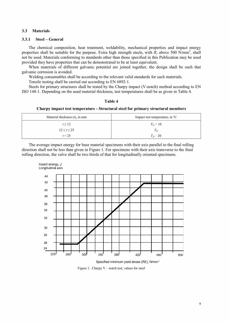
The average impact energy for base material specimens with their axis parallel to the final rolling direction shall not be less than given in Figure 1. For specimens with their axis transverse to the final rolling direction, the valve shall be two thirds of that for longitudinally oriented specimens.
Figure 1. Charpy V – notch test, values for steel
10
3.3.2 Rolled and Extruded Steel Components in Offshore Container Structures
3.3.2.1 General
Where required, steels for welding shall be made by open hearth, electric furnace or the basic oxygen steel process. Steels for the primary structure shall be killed and fine grain treated. Only materials with non-ageing properties shall be used.
3.3.2.2 Groups of Steels Structural steels for the primary structure shall be carbon, carbon-manganese, carbon-manganese
micro-alloyed steels or low-alloyed steels. For hot rolled plates and profiles, material grades specified in EN 10025, Parts 1-4, which meet the requirements in 6.1 and 6.2 shall be used.
3.3.2.3 Steel Forgings
When required forged carbon and carbon-manganese steels shall be used in the offshore container structure. Such forgings shall be made from fully-killed and fine-grain treated non-ageing steel.
For chemical and mechanical properties of alloyed steels, reference shall be made to EN 10250-2 and to EN 10250-3 Standards. The chemical composition shall be suitable for the thickness in question. Alloy steels shall be delivered in quenched and tempered condition.
The impact test temperature shall be equal to the design air temperature, TD.
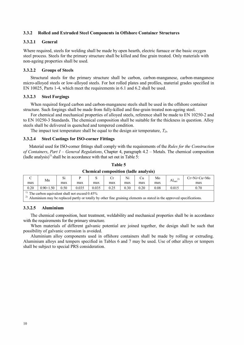
3.3.2.4 Steel Castings for ISO-corner Fittings
Material used for ISO-corner fittings shall comply with the requirements of the Rules for the Construction of Containers, Part I – General Regulations, Chapter 4, paragraph 4.2 – Metals. The chemical composition (ladle analysis)1) shall be in accordance with that set out in Table 5:
Table 5 Chemical composition (ladle analysis)
C max Mn Si
max P
max S
max Cr
max Ni
max Cu
max Mo max Almet
2) Cr+Ni+Cu+Mo max
0.20 0.90÷1.50 0.50 0.035 0.035 0.25 0.30 0.20 0.08 0.015 0.70 1) The carbon equivalent shall not exceed 0.45% 2) Aluminium may be replaced partly or totally by other fine graining elements as stated in the approved specifications.
3.3.2.5 Aluminium The chemical composition, heat treatment, weldability and mechanical properties shall be in accordance
with the requirements for the primary structure. When materials of different galvanic potential are joined together, the design shall be such that
possibility of galvanic corrosion is avoided. Aluminium alloy components used in offshore containers shall be made by rolling or extruding.
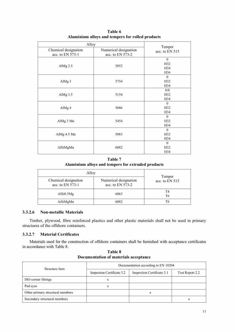
Aluminium alloys and tempers specified in Tables 6 and 7 may be used. Use of other alloys or tempers shall be subject to special PRS consideration.
11
Table 6 Aluminium alloys and tempers for rolled products
Alloy Chemical designation
acc. to EN 573-1 Numerical designation
acc. to EN 573-2
Temper acc. to EN 515
AlMg 2.5 5052
0 H32 H34 H36
AlMg 3 5754 0
H32 H34
AlMg 3.5 5154 0/0 H32 H34
AlMg 4 5086 0
H32 H34
AlMg 3 Mn 5454 0
H32 H34
AlMg 4.5 Mn 5083 0
H32 H34
AlSiMgMn 6082 0
H32 H34
Table 7 Aluminium alloys and tempers for extruded products
Alloy
Chemical designation acc. to EN 573-1
Numerical designation acc. to EN 573-2
Temper acc. to EN 515
AlSi0.5Mg 6063 T4 T6
AiSiMgMn 6082 T6
3.3.2.6 Non-metallic Materials
Timber, plywood, fibre reinforced plastics and other plastic materials shall not be used in primary structures of the offshore containers.
3.3.2.7 Material Certificates
Materials used for the construction of offshore containers shall be furnished with acceptance certificates in accordance with Table 8.
Table 8 Documentation of materials acceptance
Documentation according to EN 10204 Structure item
Inspection Certificate 3.2 Inspection Certificate 3.1 Test Report 2.2
ISO-corner fittings x
Pad eyes x
Other primary structural members x
Secondary structural members x
12
4 DESIGN OF OFFSHORE CONTAINER
4.1 General
An offshore container shall have sufficient strength to allow loading and unloading from supply vessels offshore operating in a sea state with significant wave heights up to 6 m and to withstand impact from heavy seas. In designing offshore container it shall be taken into account that local impacts, e.g. from hitting other deck cargo or rigid parts of the ship structure, may cause extreme loads in such conditions. For containers with exposed aluminium, the danger of sparking caused by the impact of aluminium against corroded steel (the thermite reaction) shall be taken into account.
Containers shall be designed as structural frames (primary structure), with non-load bearing secondary structure where necessary. Only the primary structure shall be considered in the design calculations; however, on certain types of containers, e.g. waste skips with trapezium shaped sides, with only a non-stressed cover above the bracing where the pad eyes are attached, the whole structure may be considered as a primary structure, and the design calculations may treat such a container as a monocoque construction.
Where containers are designed for stacking, and the lifting set components hang over the side of the top frame, a method of protection for those exposed parts shall be ensured, e.g. corners raised to sufficient height above the frame and roof to prevent unintentional contact with, and damage to, the lifting set.
Protruding parts on the outside of the offshore container that may catch other containers or structures shall be avoided. Protruding parts (doors handles, hatch cleats, etc.) shall be so placed or so protected that they do not catch the lifting set.
To prevent the containers from overturning (tipping) on a moving deck, they shall be designed to withstand tilting at 30° in any direction, without overturning when loaded at its maximum gross mass, with the centre of gravity considered to be at the half height of the container. For dedicated purpose containers (e.g. tank containers) the actual centre of gravity shall be used.
When preparing the specification for a service container, it is advised that the rating is chosen higher than the estimated fitted out mass. This will allow for changes in the amount and mass of equipment fitted in a container during its operational life, and carrying a certain amount of non-permanent equipment.
The design air temperature TD shall not be higher than the (statistically) lowest daily average temperature for the area where the offshore container is to operate and in no case shall be higher than –20°C.
4.2 Structural Strength
The strength of container structure shall conform to the requirements of EN 12079-1 paragraph 5.2.
5 TESTS OF OFFSHORE CONTAINERS
5.1 General
The tests described in 5.3 to 5.5 of this Chapter are required for all offshore container prototypes, and shall be considered as design requirements.
A container selected for type testing (a prototype) shall be representative of the production units and not a hand built pre-production development container. It shall be built in conformity with an approved documentation and using technology comparable to those planned for subsequent production.
The test load shall be evenly distributed inside the container. If it is not possible to place all the test load inside the container, some of it may be placed outside or under the container, provided that this gives a loading on the structure similar to the distribution of the container loading in operating condition.
If the container has an additional cargo deck, the test load shall be evenly divided between the floor and the additional deck. If the additional deck is removable, it will be necessary to carry out the test with the test load divided between the additional deck and the floor, as well as with the whole test load on the floor.
13
5.2 Test Equipment
5.2.1 Test Load
The test load shall be verified using calibrated weights or calibrated load cells. Use of the following forms of test load is permitted: water or sand bags, calibrated test blocks, free weights and suitable test rigs.
5.2.2 Calibration
The load cells shall be calibrated annually in accordance with the requirements of EN ISO 7500-1 Standard, to an accuracy of ±2%. Test blocks shall be calibrated at least every 2 years. The measured mass, in kilograms, shall be legibly and durably marked on each block. Care shall be taken in the storage of calibrated concrete blocks so as to prevent absorption of the water having influence on the actual block mass.
5.3 Lifting Test
5.3.1 General
The container shall be lifted by a lifting set with a single strand angle to the vertical equal to the design angle. Where the lifting set intended for use with the container is used for lifting, care shall be taken to ensure that no overloading, deformation or distortion is induced in the lifting set. Such a set shall be visually inspected after the load test.
The container shall be carefully lifted in such a way that no significant acceleration forces occur. It shall be held for 5 minutes before measurements are taken and examinations made.
5.3.2 All-point Lifting
The container shall be loaded to give a total mass of 2.5R (the test load mass shall amount to 2.5R – T) and lifted using all the pad eyes.
After the test, the container shall show no permanent deformation or other damage.
5.3.3 Two-point Lifting
An offshore container fitted with four pad eyes, loaded to gross mass 1.5R (the mass of test load shall be 1.5R – T) shall also be lifted from only two pad eyes, situated diagonally opposite each other.
After the test, the container shall show no permanent deformation or other damage.
5.4 Vertical impact test
5.4.1 General
The container, with its internal test load corresponding to payload P, shall be either lowered or dropped on to a workshop floor of concrete or other rigid structure. This floor may be covered with a sheathing of wooden planks with a thickness not exceeding 50 mm.
If the container is lowered from a crane, the suspending wire and hook may dampen the impact compared to a free-fall drop test. Therefore the impact speed should be greater if a lowering test is used.
In both cases, the container shall be so inclined that each of the bottom side and end rails connected to the lowest corner forms an angle of not less than 5° with the floor. However, the greatest height difference between the highest and lowest point of the underside of the container corners should not be more than 400 mm.
The impacting corner shall be the one expected to have the lowest rigidity. On closed dry bulk cargo containers this will normally be at the door end.
After the lowering or drop test, the container shall show no permanent deformations or other damages. Cracks in welds and minor deformations may be repaired.
14
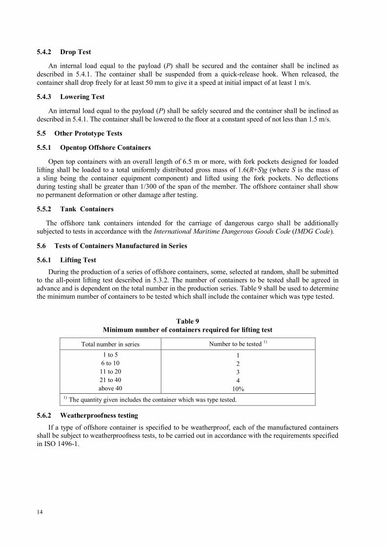
5.4.2 Drop Test
An internal load equal to the payload (P) shall be secured and the container shall be inclined as described in 5.4.1. The container shall be suspended from a quick-release hook. When released, the container shall drop freely for at least 50 mm to give it a speed at initial impact of at least 1 m/s.
5.4.3 Lowering Test
An internal load equal to the payload (P) shall be safely secured and the container shall be inclined as described in 5.4.1. The container shall be lowered to the floor at a constant speed of not less than 1.5 m/s.
5.5 Other Prototype Tests
5.5.1 Opentop Offshore Containers
Open top containers with an overall length of 6.5 m or more, with fork pockets designed for loaded lifting shall be loaded to a total uniformly distributed gross mass of 1.6(R+S)g (where S is the mass of a sling being the container equipment component) and lifted using the fork pockets. No deflections during testing shall be greater than 1/300 of the span of the member. The offshore container shall show no permanent deformation or other damage after testing.
5.5.2 Tank Containers
The offshore tank containers intended for the carriage of dangerous cargo shall be additionally subjected to tests in accordance with the International Maritime Dangerous Goods Code (IMDG Code).
5.6 Tests of Containers Manufactured in Series
5.6.1 Lifting Test During the production of a series of offshore containers, some, selected at random, shall be submitted
to the all-point lifting test described in 5.3.2. The number of containers to be tested shall be agreed in advance and is dependent on the total number in the production series. Table 9 shall be used to determine the minimum number of containers to be tested which shall include the container which was type tested.
Table 9 Minimum number of containers required for lifting test
Total number in series Number to be tested 1)
1 to 5 6 to 10 11 to 20 21 to 40 above 40
1 2 3 4
10% 1) The quantity given includes the container which was type tested.
5.6.2 Weatherproofness testing
If a type of offshore container is specified to be weatherproof, each of the manufactured containers shall be subject to weatherproofness tests, to be carried out in accordance with the requirements specified in ISO 1496-1.
15
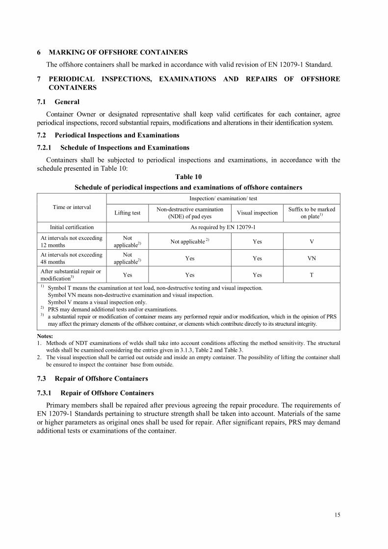
6 MARKING OF OFFSHORE CONTAINERS
The offshore containers shall be marked in accordance with valid revision of EN 12079-1 Standard.
7 PERIODICAL INSPECTIONS, EXAMINATIONS AND REPAIRS OF OFFSHORE CONTAINERS
7.1 General
Container Owner or designated representative shall keep valid certificates for each container, agree periodical inspections, record substantial repairs, modifications and alterations in their identification system.
7.2 Periodical Inspections and Examinations
7.2.1 Schedule of Inspections and Examinations
Containers shall be subjected to periodical inspections and examinations, in accordance with the schedule presented in Table 10:
Table 10 Schedule of periodical inspections and examinations of offshore containers
Inspection/ examination/ test Time or interval
Lifting test Non-destructive examination (NDE) of pad eyes Visual inspection Suffix to be marked
on plate1)
Initial certification As required by EN 12079-1
At intervals not exceeding 12 months
Not applicable2) Not applicable 2) Yes V
At intervals not exceeding 48 months
Not applicable2) Yes Yes VN
After substantial repair or modification3) Yes Yes Yes T
1) Symbol T means the examination at test load, non-destructive testing and visual inspection. Symbol VN means non-destructive examination and visual inspection. Symbol V means a visual inspection only. 2) PRS may demand additional tests and/or examinations. 3) a substantial repair or modification of container means any performed repair and/or modification, which in the opinion of PRS
may affect the primary elements of the offshore container, or elements which contribute directly to its structural integrity.
Notes: 1. Methods of NDT examinations of welds shall take into account conditions affecting the method sensitivity. The structural
welds shall be examined considering the entries given in 3.1.3, Table 2 and Table 3. 2. The visual inspection shall be carried out outside and inside an empty container. The possibility of lifting the container shall
be ensured to inspect the container base from outside.
7.3 Repair of Offshore Containers
7.3.1 Repair of Offshore Containers
Primary members shall be repaired after previous agreeing the repair procedure. The requirements of EN 12079-1 Standards pertaining to structure strength shall be taken into account. Materials of the same or higher parameters as original ones shall be used for repair. After significant repairs, PRS may demand additional tests or examinations of the container.
16
ATTACHMENT
Offshore Container Lifting Sets
1. GENERAL
The lifting set (wire rope or chain type) shall be specially designed for use with given type of offshore container. The sling legs shall be secured to pad eyes located on the container by shackles, where the shackle pins shall be protected against unauthorized or accidental unscrewing. In service, the lifting sets shall not be removed from containers, unless for replacement if necessary.
2. DESIGNING AND SELECTION OF LIFTING SETS
2.1 General
Slings shall be rated for their intended angle of their legs inclination to vertical. In all cases four leg slings shall be rated as for three leg slings. In no case shall a sling be rated for an angle of the sling leg to the vertical in excess of 45°
Note: For specific angles less than 45° the sling may be rated at the working load limit (WLL) according to the particular angle of the legs to the vertical. This should be calculated by the formula: – For two leg slings used at an angle β to the vertical: WLL = 2 x WLL for a single leg x cos β , – For four leg slings used at an angle β of any leg to the vertical: WLL = 3 x WLL for a single leg x cos β .
Where two 2-leg slings are selected to function as a 4-leg sling, they shall be calculated as for a 4-leg sling
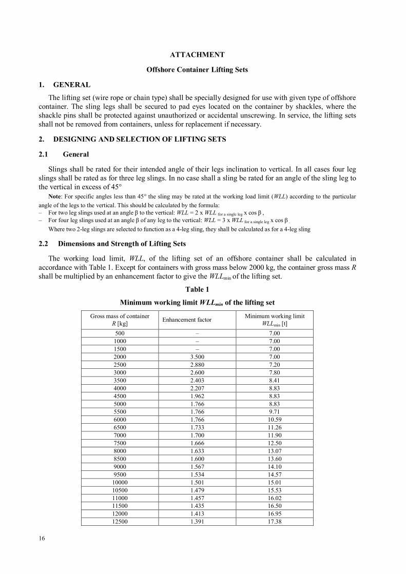
2.2 Dimensions and Strength of Lifting Sets
The working load limit, WLL, of the lifting set of an offshore container shall be calculated in accordance with Table 1. Except for containers with gross mass below 2000 kg, the container gross mass R shall be multiplied by an enhancement factor to give the WLLmin of the lifting set.
Table 1
Minimum working limit WLLmin of the lifting set
Gross mass of container R [kg] Enhancement factor Minimum working limit
WLLmin [t] 500 – 7.00 1000 – 7.00 1500 – 7.00 2000 3.500 7.00 2500 2.880 7.20 3000 2.600 7.80 3500 2.403 8.41 4000 2.207 8.83 4500 1.962 8.83 5000 1.766 8.83 5500 1.766 9.71 6000 1.766 10.59 6500 1.733 11.26 7000 1.700 11.90 7500 1.666 12.50 8000 1.633 13.07 8500 1.600 13.60 9000 1.567 14.10 9500 1.534 14.57
10000 1.501 15.01 10500 1.479 15.53 11000 1.457 16.02 11500 1.435 16.50 12000 1.413 16.95 12500 1.391 17.38
17
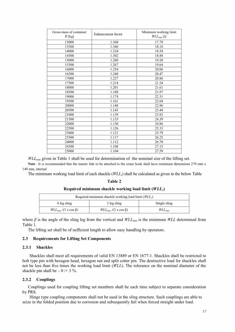
Gross mass of container R [kg] Enhancement factor Minimum working limit
WLLmin [t] 13000 1.368 17.79 13500 1.346 18.18 14000 1.324 18.54 14500 1.302 18.88 15000 1.280 19.20 15500 1.267 19.64 16000 1.254 20.06 16500 1.240 20.47 17000 1.227 20.86 17500 1.214 21.24 18000 1.201 21.61 18500 1.188 21.97 19000 1.174 22.31 19500 1.161 22.64 20000 1.148 22.96 20500 1.143 23.44 21000 1.139 23.92 21500 1.135 24.39 22000 1.130 24.86 22500 1.126 25.33 23000 1.121 25.79 23500 1.117 26.25 24000 1.112 26.70 24500 1.108 27.15 25000 1.104 27.59
WLLmin given in Table 1 shall be used for determination of the nominal size of the lifting set. Note : It is recommended that the master link to be attached to the crane hook shall have minimum dimensions 270 mm x
140 mm, internal The minimum working load limit of each shackle (WLLs) shall be calculated as given in the below Table
Table 2
Required minimum shackle working load limit (WLLs)
Required minimum shackle working load limit (WLLs)
4 leg sling 2 leg sling Single sling
WLLmin /(3 x cos β) WLLmin /(2 x cos β) WLLmin
where β is the angle of the sling leg from the vertical and WLLmin is the minimum WLL determined from Table 1.
The lifting set shall be of sufficient length to allow easy handling by operators.
2.3 Requirements for Lifting Set Components
2.3.1 Shackles
Shackles shall meet all requirements of valid EN 13889 or EN 1677-1. Shackles shall be restricted to bolt type pin with hexagon head, hexagon nut and split cotter pin. The destructive load for shackles shall not be less than five times the working load limit (WLL). The tolerance on the nominal diameter of the shackle pin shall be – 0 /+ 3 %.
2.3.2 Couplings
Couplings used for coupling lifting set members shall be each time subject to separate consideration by PRS.
Hinge type coupling components shall not be used in the sling structure. Such couplings are able to seize in the folded position due to corrosion and subsequently fail when forced straight under load.
18
2.3.3 Wire Rope Slings Wire rope slings shall meet the requirements of EN 13414-1 Standard with the below restrictions:
– wire rope shall be 6-stranded and of one of type 6 x 19 or 6 x 36; – the termination of wire rope shall be a ferrule secured thimble.
The wire ropes shall be manufactured by PRS approved manufacturers. Round section, galvanized steel wires of grade 1770 or 1960 shall be used for the manufacture of wire ropes. The working load limit (WLL) shall be calculated on the basis of the actual rope grade used.
2.3.4 Chain Slings
The chain slings shall meet the requirements of EN 13414-1 Standard.
2.4 Materials and Welding
2.4.1 Impact Testing
Steels used for slings shall be impact tested by the Charpy impact (V-notch) method in accordance with valid EN ISO 148-1 Standard. The impact test temperature shall be equal to the design air temperature and the minimum average impact energy shall be 42 J. However, for welded components (chains, links, rings) it shall be sufficient only to take impact test samples in the weld with the notch centred in the fusion line. Where the cross-section of the material to be tested is too small to allow the standard test specimen (10 x 10 mm) to be taken, the required energy values shall be reduced as follows: – 10 mm × 7.5 mm: 5/6 of the above value, – 10 mm × 5 mm: 2/3 of the above value.
For tests where the size of the test piece is too small (diameter less than 13 mm), tests may be carried out on sample material which shall be of the same specification and heat treatment.
2.4.2 Galvanising of Sling Components
Galvanising shall only be carried out under the control of the manufacturer of the component.
2.4.3 Welding
Welding of sling components shall be performed in accordance with qualified welding procedure, acc. to valid revision of EN ISO 15613 Standard. Welders shall be certified by PRS.
2.5 Acceptance Certificates
2.5.1 Material Certificates
The materials used in all sling components shall be supplied with an inspection certificate type 3.1 or, in the case of materials in ferrules and thimbles, inspection certificate type 2.2 (designation according to EN 10204 Standard).
2.5.2 Acceptance Certificates for Single Components of Slings
Single components used in slings, shall have certificates containing the information specified in the relevant product standard together with the following, as a minimum: – manufacturer’s name, logo and contact data, – date of issue for the certificate (YYYY-MM-DD), – certificate number, – identification of the relevant product standard, – material specification including chemical composition and mechanical properties, – results from tests specified in the relevant product standard and this standard, – record of the unique identification number or mark carried by the component, – manufacturer’s authorized signature.
19
2.5.3 Sling Acceptance Certificates
Certificates of complete sling acceptance shall contain the below data, as a minimum: – manufacturer’s name, logo and contact data, – date of issue for the certificate (YYYY-MM-DD), – certificate number, – description of the sling, including unique identification number or mark, – reference to each single component unique identification mark (if new components are installed,
before re-certification reference shall be given to previous certificate number and the new component unique identification mark),
– nominal size and length of the sling, – working load limit (WLL) together with the appropriate angle to the vertical for multi-leg slings, – date of sling manufacture or re-certification, – a statement that the sling described has been designed, manufactured and tested in accordance with
this Publication and valid revision of EN 12079-2 Standard, – manufacturer’s authorized signature, – for wire rope slings, the grade of terminal fittings and the rope, together with a statement that the sling
conforms to valid EN 13414-1, – for chain slings, the grade mark 8 and a statement confirming that the sling conforms to valid EN 818-4
and providing cross reference to the results of any final testing of mechanical properties after heat treatment.
2.6 Marking of Slings
Slings used for lifting offshore containers shall be marked in accordance with valid EN 12079-2 Standard.