Embed Size (px)
Citation preview
GUIDE FOR CERTIFICATION OF
OFFSHORE CONTAINERSFEBRUARY 2020
American Bureau of ShippingIncorporated by Act of Legislature ofthe State of New York 1862
© 2020 American Bureau of Shipping. All rights reserved.1701 City Plaza DriveSpring, TX 77389 USA
Foreword (1 February 2020)IMO has issued MSC/Circ.860 Guidelines for the approval of offshore containers handled in open seas.This circular is intended to assist the competent authorities in developing the requirements for approvingthe offshore containers. IMO requires that all intermodal containers conform to the requirements of theInternational Convention for Safe Containers (CSC). The requirements of the CSC convention may not beapplicable to offshore containers primarily due to non-standard designs, exposure to the marineenvironment for extended periods as well as the lifting of offshore containers by padeyes. EN 12079 hasbeen published based on the MSC/Circ.860 and is currently used as an International industry standard toapprove offshore containers.
Containers built to the ABS Guide for Certification of Offshore Containers will meet all the requirementsof MSC/Circ.860, EN 12079:2006 and ISO 10855:2018. This Guide provides guidance for manufacturingfacilities to build offshore containers. It also serves to assist the ABS Engineers and Surveyors in certifyingoffshore containers around the globe.
This Guide becomes effective on the first day of the month of publication.
Users are advised to check periodically on the ABS website www.eagle.org to verify that this version ofthis Guide is the most current.
We welcome your feedback. Comments or suggestions can be sent electronically by email [email protected].
ABS GUIDE FOR CERTIFICATION OF OFFSHORE CONTAINERS • 2020 ii
GUIDE FOR CERTIFICATION OF
OFFSHORE CONTAINERS
CONTENTSCHAPTER 1 General Information.............................................................................1
Section 1 General.............................................................................. 3Section 2 Certification Procedure...................................................... 5Section 3 Definitions.......................................................................... 9Section 4 Symbols........................................................................... 12Section 5 Quality Assessment......................................................... 13Section 6 Terms and Conditions...................................................... 17
CHAPTER 2 Offshore Containers.......................................................................... 21Section 1 General............................................................................ 24Section 2 Materials and Welding..................................................... 26Section 3 Design..............................................................................30Section 4 Prototype Testing............................................................. 38Section 5 Production........................................................................41Section 6 Marking and Data Plate................................................... 44
CHAPTER 3 Lifting Sets......................................................................................... 47Section 1 General............................................................................ 48Section 2 Materials and Welding..................................................... 49Section 3 Design..............................................................................50Section 4 Marking............................................................................ 55
CHAPTER 4 In-Service Inspections.......................................................................58Section 1 General............................................................................ 59Section 2 Schedule of Inspections for Offshore Containers............ 60Section 3 Schedule of Inspections for Lifting Sets...........................62Section 4 Inspection Plates/Tags.....................................................63Section 5 Repair and Modification Procedures................................67Appendix 1 ABS Recognized Standards ........................................... 69Appendix 2 Certification Requirements for Offshore Tank
Containers/Portable Tanks and MEGC ...........................73Appendix 3 Determination of Working Load Limit of the WLLmin
Lifting Set.........................................................................75Appendix 4 Container Corner Castings ............................................. 77Appendix 5 Existing Offshore Containers........................................... 80
ABS GUIDE FOR CERTIFICATION OF OFFSHORE CONTAINERS • 2020 iii
C H A P T E R 1 General Information
CONTENTSSECTION 1 General..................................................................................................3
1 Scope..............................................................................................32 Relationship with Other Standards, Codes and Regulations..........3
2.1 IMO-MSC/Circ.860............................................................ 32.2 ISO 10855:2018.................................................................32.3 EN 12079:2006..................................................................42.4 IMDG, US DOT, RID/ADR................................................. 42.5 ABS Guide for Dropped Object Prevention on
Offshore Units and Installations.........................................4
SECTION 2 Certification Procedure....................................................................... 51 Certification Procedure for Offshore Containers.............................5
1.1 Application for Certification................................................ 51.2 Design Review...................................................................51.3 Quality Control................................................................... 51.4 Production..........................................................................61.5 ABS Production Certificate................................................ 61.6 Certification to Other Standards........................................ 6
2 Certification procedure for the Lifting Set....................................... 72.1 Components...................................................................... 72.2 Application for Certification................................................ 72.3 Design Review...................................................................82.4 Quality Control................................................................... 82.5 Production..........................................................................82.6 ABS Production Certificate................................................ 8
SECTION 3 Definitions............................................................................................ 91 Assembly Secured Shackle............................................................92 Breaking Force............................................................................... 93 Corner Fitting..................................................................................94 Designer......................................................................................... 95 Lifting Set........................................................................................96 Non-conformance........................................................................... 97 Offshore Container......................................................................... 98 Original Equipment Manufacturer (OEM)....................................... 99 Owner............................................................................................. 910 Permanent Equipment....................................................................911 Primary Structure............................................................................9
11.1 Essential/Non-redundant Primary Structure.................... 1011.2 Non-essential Primary Structure......................................10
12 Production Units........................................................................... 10
ABS GUIDE FOR CERTIFICATION OF OFFSHORE CONTAINERS • 2020 1
13 Proof Load.................................................................................... 1014 Proof Test......................................................................................1015 Prototype...................................................................................... 1016 Prototype Testing .........................................................................1017 Secondary Structure.....................................................................10
SECTION 4 Symbols.............................................................................................. 12
SECTION 5 Quality Assessment...........................................................................131 General.........................................................................................132 Quality Manual..............................................................................133 Quality Plan.................................................................................. 134 Quality Assessment......................................................................14
4.1 Initial Assessment............................................................144.2 Annual Assessment......................................................... 154.3 Renewal Assessment...................................................... 154.4 Quality Assessment Report............................................. 154.5 Overdue Assessment...................................................... 15
5 Factory Approval Certificate......................................................... 165.1 Certificate.........................................................................165.2 Validity............................................................................. 16
SECTION 6 Terms and Conditions....................................................................... 171 Container/Lifting Set Certification Application...............................172 Representations as to Certification...............................................173 Suspension of Certification...........................................................174 Validity.......................................................................................... 175 Disagreement............................................................................... 186 Limitation...................................................................................... 187 Hold Harmless.............................................................................. 188 Arbitration..................................................................................... 189 Time Bar to Legal Action.............................................................. 1910 Limitation of Liability..................................................................... 1911 Scope of Certification....................................................................1912 Confidentiality............................................................................... 2013 Emblem.........................................................................................20
FIGURE 1 Emblem – ABS Offshore Container (ABS OC).................... 20
ABS GUIDE FOR CERTIFICATION OF OFFSHORE CONTAINERS • 2020 2
C H A P T E R 1 General Information
S E C T I O N 1 General
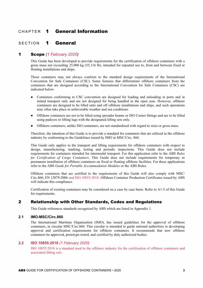
1 Scope (1 February 2020)This Guide has been developed to provide requirements for the certification of offshore containers with agross mass not exceeding 25,000 kg (55,116 lb), intended for repeated use to, from and between fixed orfloating installations and ships.
These containers may not always conform to the standard design requirements of the InternationalConvention for Safe Containers (CSC). Some features that differentiate offshore containers from thecontainers that are designed according to the International Convention for Safe Containers (CSC) areindicated below:
● Containers conforming to CSC convention are designed for loading and unloading in ports and ininland transport only and are not designed for being handled in the open seas. However, offshorecontainers are designed to be lifted onto and off offshore installations and ships, and such operationsmay often take place in unfavorable weather and sea conditions.
● Offshore containers are not to be lifted using spreader beams or ISO Corner fittings and are to be liftedusing padeyes or lifting lugs with the designated lifting sets only.
● Offshore containers, unlike ISO containers, are not standardized with regard to sizes or gross mass.
Therefore, the intention of this Guide is to provide a standard for containers that are utilized in the offshoreindustry by conforming to the Guidelines issued by IMO in MSC/Circ. 860.
This Guide only applies to the transport and lifting requirements for offshore containers with respect todesign, manufacturing, marking, testing and periodic inspections. This Guide does not includerequirements for containers intended for intermodal transport. For this application refer to the ABS Rulesfor Certification of Cargo Containers. This Guide does not include requirements for temporary orpermanent installation of offshore containers on fixed or floating offshore facilities. For these applicationsrefer to the ABS Guide for Portable Accommodation Modules or the ABS Rules.
Offshore containers that are certified to the requirements of this Guide will also comply with MSC/Circ.860, EN 12079:2006 and ISO 10855:2018. Offshore Container Production Certificates issued by ABSwill indicate this compliance.
Certification of existing containers may be considered on a case by case basis. Refer to A1-5 of this Guidefor requirements.
2 Relationship with Other Standards, Codes and RegulationsThis Guide references standards recognized by ABS which are listed in Appendix 1.
2.1 IMO-MSC/Circ.860The International Maritime Organization (IMO), has issued guidelines for the approval of offshorecontainers, in circular MSC/Circ.860. This circular is intended to guide national authorities in developingapproval and certification requirements for offshore containers. It recommends that new offshorecontainers be approved, prototype tested, and certified by duly authorized bodies.
2.2 ISO 10855:2018 (1 February 2020)ISO 10855:2018 is a standard used in the offshore industry for the certification of offshore containers andassociated lifting sets.
ABS GUIDE FOR CERTIFICATION OF OFFSHORE CONTAINERS • 2020 3
This standard consists of three parts as described below:
● EN 10855:2018, Part 1: Design, Manufacturing and Marking of Offshore Containers
● EN 10855:2018, Part 2: Manufacturing and Marking of Lifting Set
● EN 10855:2018, Part 3: Periodic Inspection, Examination and Testing
2.3 EN 12079:2006EN 12079:2006 is a standard used in the offshore industry for the certification of offshore containers andassociated lifting sets.
This standard consists of three parts as described below:
● EN 12079:2006, Part 1: Offshore Containers - Design, Manufacturing and Marking
● EN 12079:2006, Part 2: Lifting sets - Design, Manufacturing and Marking
● EN 12079:2006, Part 3: Periodic Inspection, Examination and Testing
2.4 IMDG, US DOT, RID/ADROffshore Containers that are intended for the carriage of dangerous cargo are required to be in compliancewith the International Maritime Dangerous Goods (IMDG) Code.
Some of the offshore containers may also be required to conform to other national and internationalstandards and regulations such as United States Department of Transport (US DOT), Regulationsconcerning the International Carriage of Dangerous Goods by Rail (RID) and European Agreementconcerning the International Carriage of Dangerous Goods by Road (ADR), etc.
2.5 ABS Guide for Dropped Object Prevention on Offshore Units and Installations(1 February 2020)The ABS Guide has been developed to provide users with specific guidance and criteria on a droppedprevention program, which corresponds to a growing industry-wide development to mitigate and eliminatethe hazards imposed by dropped objects. The application of the Guide to offshore containers is optional.Offshore containers may be reviewed for compliance to the ABS Guide for the Prevention of DroppedObjects on Offshore Units and Installations at the request of the designer.
Chapter 1 General InformationSection 1 General 1-1
ABS GUIDE FOR CERTIFICATION OF OFFSHORE CONTAINERS • 2020 4
C H A P T E R 1 General Information
S E C T I O N 2 Certification Procedure
1 Certification Procedure for Offshore ContainersThe certification procedure outlined below is a typical procedure which will facilitate the certification ofoffshore containers to this Guide. ABS may consider alternative procedures, provided they are not lesseffective than the requirements indicated in this Guide.
1.1 Application for CertificationAn application is to be submitted by the designer or manufacturer who has legal rights to the design. Thedesigner and manufacturer may not be the same entity and are to be indicated on the application.
The application is to be submitted with, but not limited to, the following:
i) Design drawings including but not limited to the following information:
● Dimensions
● Maximum gross mass and payload
● Scantling of members
● Material properties
● Padeye details
● Welding details
● Markings
ii) Design calculations
iii) Testing results (if applicable)
iv) Declaration for the absence of asbestos
Applications for additional units to be certified under an approved design are to include at least theapplication and marking drawings if the owner has changed them.
Revisions to an existing ABS approved design will require an application which is to be submitted with,but not limited to, the applicable documents indicated above. Submitted documents are to completelydescribe the changes.
1.2 Design ReviewThe documents submitted with the application will be reviewed by an ABS engineer. The engineer willevaluate the design under the requirements of this Guide and any other requested Rules, regulations orstandards. Upon a successful review, an ABS review letter with test agenda, if applicable, will be returnedindicating that the design meets the requirements of this Guide. The prototype test agenda is provided onlyafter all review items are addressed.
The design is not approved until the prototype test is conducted in the presence of an ABS Surveyor inaccordance with the prototype test agenda specified by ABS.
1.3 Quality ControlThe manufacturing facility is to submit a quality manual to the ABS Surveyor which describes the qualitysystem. The Surveyor will review the manual to verify aspects of the production of the container are
ABS GUIDE FOR CERTIFICATION OF OFFSHORE CONTAINERS • 2020 5
addressed in the manual. Following a successful review of the manual, a quality audit will be performed atthe manufacturing facility to verify that the system outlined in the manual is in place and functioningproperly.
Upon a successful quality audit, the ABS Surveyor will issue a Factory Approval Certificate. Thecertificate will be valid for 5 years with annual endorsements required.
Notes:
1 A quality control document for the manufacturing facility is required to be submitted only if the facility issubmitting for the first design to be manufactured at the facility.
2 Any updates to the quality control documents are to be submitted for review. The document is to be updated if anew design requiring additional quality procedures is to be produced at the facility.
1.4 ProductionUpon a successful design review, prototype test and quality assessment, the manufacturing facility maybegin production under the surveillance of an ABS Surveyor.
The ABS Surveyor will initially request a meeting to discuss inspection schedules, hold points and otherrelated items. The Welding Procedure Specifications (WPS) and Welder Qualifications will be reviewedand approved by the ABS Surveyor prior to production.
Production testing is to be carried out in the presence of an ABS Surveyor or quality representativenominated by the manufacturer as indicated in the ABS approved quality document. The Surveyor is to“walk the production line” during each attendance to verify that the quality system continues to functionproperly.
The below documents are to be presented to the ABS Surveyor at the time of final inspection in an as-builtdossier in order to support the certification of the offshore container. The documents are to include, but arenot limited to the following:
i) Material certificates
ii) Material Traceability Reports (MTR) for primary structure
iii) Fabrication inspection reports
iv) Dimensional control reports
v) Nondestructive Testing (NDT) reports
vi) Production testing reports
vii) Pressure testing records
1.5 ABS Production CertificateAn ABS Production Certificate will be issued by the Surveyor following a successful review of the as-builtdossier and final inspection. Additionally, the certificate will reference the ABS engineering approval letterand prototype test certificate, applicable to the container design.
1.6 Certification to Other StandardsWhen the application includes a request for certification to governmental requirements, internationalconventions, or other standards, the submittal is to include all necessary required information. Theseadditional requirements are to be indicated in the certificate.
Chapter 1 General InformationSection 2 Certification Procedure 1-2
ABS GUIDE FOR CERTIFICATION OF OFFSHORE CONTAINERS • 2020 6
2 Certification procedure for the Lifting SetThe certification procedure outlined below is a typical procedure which will facilitate the certification ofthe lifting sets. ABS may consider alternative procedures, provided they are not less effective than therequirements indicated in this Guide.
Lifting sets are to be assembled from the various components described within this Guide. Thecomponents are to meet the requirements of this Guide and applicable standards and be presented to themanufacturer of the lifting set with supporting documentation. The lifting set will be certified in theassembled condition by the attending ABS Surveyor.
2.1 ComponentsManufacturers of the following components are to submit the component for certification through the ABSType Approval program.
● Shackles
● Chains
● Links (master links and master link assemblies, intermediate links, end links)
● Couplings
The ABS Type Approval procedure as well as the application can be found on the ABS web site,www.eagle.org. The above components are to be presented to the lifting set manufacturer with traceabilityto the ABS Type Approval certificate.
Other components such as wire rope, ferrules, and thimbles do not require ABS Type Approval. However,they are to be presented to the lifting set manufacturer with a 3.1 Certificate in accordance with ISO 10474or another standard recognized by ABS.
2.2 Application for CertificationAn application is to be submitted by the designer or manufacturer who has legal rights to the design of thelifting set. The designer and manufacturer may not be the same entity and are to be indicated on theapplication.
The application is to be submitted with, but not limited to, the following:
i) Specification of the lifting set, along with the following
● Applicable standards
● Material specification
● Dimensions of all the components
● Working Load Limit (WLL)
● Proof Load (PL)
● Breaking Load (BL)
ii) Drawings of lifting set and its components
iii) Calculations demonstrating how the lifting set components were selected, including determinationof required strength
iv) Description of all the manufacturing/assembly procedures (e.g. for wire rope sling: the assemblyof the sling legs with terminal, etc.)
v) Marking details on the tags
vi) Description of the test methods and procedures for all relevant prototype and production tests
Chapter 1 General InformationSection 2 Certification Procedure 1-2
ABS GUIDE FOR CERTIFICATION OF OFFSHORE CONTAINERS • 2020 7
vii) Type approval/3.1 certificates for the components according to 1-2/2.1
Applications for additional units to be certified under an approved design are to include at least theapplication and marking drawings if the owner has changed them.
Revisions to an existing ABS approved design will require an application which is to be submitted with,but not limited to, the applicable documents indicated above. Submitted documents are to completelydescribe the changes.
2.3 Design ReviewThe documents submitted with the application will be reviewed by an ABS engineer. The engineer willevaluate the design under the requirements of this Guide and any other requested Rules, regulations orstandards. Upon a successful review, an ABS review letter with test agenda, if applicable, will be returnedindicating that the design meets the requirements of this Guide. The prototype test agenda is only providedafter all review items are addressed.
The design is not approved until the prototype test is conducted in the presence of an ABS Surveyor inaccordance with the test agenda specified by ABS.
2.4 Quality ControlThe manufacturing facility is to submit a quality manual to the ABS Surveyor which describes the qualitysystem. The Surveyor will review the manual to verify aspects of the production of the lifting set areaddressed in the manual. Following a successful review of the manual, a quality audit will be performed atthe manufacturing facility to verify that the system outlined in the manual is in place and functioningproperly.
Upon a successful quality audit, the ABS Surveyor will issue a Factory Approval Certificate. Thecertificate will be valid for 5 years with annual endorsements required.
Notes:
1 A quality control document for the manufacturing facility is required to be submitted only if the facility issubmitting for the first design to be manufactured at the facility.
2 Any updates to the quality control documents are to be submitted for review. The document is to be updated if anew design requiring additional quality procedures is to be produced at the facility.
2.5 ProductionUpon a successful design review, prototype testing and quality assessment, the manufacturing facility maybegin production of lifting sets in accordance with the approved design.
Testing carried out during the production phase are to be in accordance with the relevant sling orcomponent standards.
2.6 ABS Production CertificateAn ABS Production Certificate will be issued by the Surveyor following a successful review of the as-builtdossier (which includes the ABS Type Approval or 3.1 certificates for the components of the Lifting Set)and final inspection. Additionally, the certificate will reference the ABS engineering approval letter andprototype test certificate, applicable to the lifting set design.
Chapter 1 General InformationSection 2 Certification Procedure 1-2
ABS GUIDE FOR CERTIFICATION OF OFFSHORE CONTAINERS • 2020 8
C H A P T E R 1 General Information
S E C T I O N 3 Definitions
1 Assembly Secured ShackleA shackle fitted to a sling leg and secured by a seal or similar device, so as to signal unambiguously,whether or not the shackle has been exchanged.
2 Breaking ForceThe maximum load at which a tensile failure occurs in the sample of wire rope being tested.
3 Corner FittingA corner fitting is a fixture consisting of standard apertures and faces which provide a common interfacefor handling and securing containers.
4 DesignerThe person or legal entity that has proprietary rights to the design and its use. This may be the OEM.
5 Lifting SetItems of integrated equipment used to connect the offshore container to the lifting appliance. This cancomprise one or multi leg slings (with or without a top leg) and shackles, whether assembly secured or not.
6 Non-conformanceNon-fulfilment of a specified requirement.
7 Offshore ContainerA portable unit with gross mass not exceeding 25,000 kg (55116 lb), for repeated use in the transport ofgoods or equipment handled in open seas to, from and between fixed and/or floating installations andships.
Note: The unit incorporates permanently installed equipment for lifting and handling and may include equipment forfilling, emptying, cooling, heating, etc.
8 Original Equipment Manufacturer (OEM)The person or legal entity that has the legal or patent rights to produce the material, component, product, orsystem.
9 OwnerLegal owner of the offshore container or the delegated nominee of that body.
10 Permanent EquipmentEquipment that is attached to the container and which is not cargo.
Note: This may include lifting sets, refrigeration units, shelves, securing points, garbage compactors.
11 Primary StructureLoad carrying and supporting frames, load carrying panels, supporting structures for tanks, padeyes, etc.
ABS GUIDE FOR CERTIFICATION OF OFFSHORE CONTAINERS • 2020 9
Primary structure is divided into the following two subgroups:
11.1 Essential/Non-redundant Primary Structure (1 February 2020)Main structural elements which transfer the cargo load to the crane hook (i.e., forming the “load path”from the payload to the lifting sling) include but are not limited to:
● Top and bottom side rails
● Top and bottom end rails
● Corner posts
● Padeyes
● Fork lift pockets
Other primary structure may also be considered as essential/non-redundant.
11.2 Non-essential Primary StructureStructural elements such as floor plates, protective frame members, etc. which do not have their functionalrequirement as specified in 1-3/11.1 are to be categorized here. Side and roof panels (including corrugatedpanels), are not considered to be part of primary structure and are not be taken into account whenevaluating the strength of the container.
12 Production UnitsProduction units are identical containers built under conditions which duplicate, insofar as is practicable,the conditions under which the prototype was built.
13 Proof LoadThe specific tension applied to a sling or component in the performance of a proof test
14 Proof TestA non-destructive tension test of the sling or components.
15 PrototypePrototype is a representative unit of a series of identical containers built under conditions which duplicate,insofar as is practicable, the conditions under which all of the containers in the series are to be fitted.
16 Prototype TestingThis is the destructive and nondestructive testing of the materials and components presented for evaluationof the original design of a product. If a Surveyor’s witness is required, this may not be waived under anysections of the Rules, unless it is done by a recognized third party.
17 Secondary StructureParts which are not considered as load carrying for the purpose of the design calculations, including thefollowing components:
● Doors, wall and roof panels;
● Panels stiffeners and corrugations;
● Structural components used for tank protection only;
● Internal securing points.
Chapter 1 General InformationSection 3 Definitions 1-3
ABS GUIDE FOR CERTIFICATION OF OFFSHORE CONTAINERS • 2020 10
Note: Not all container walls are corrugated.
Chapter 1 General InformationSection 3 Definitions 1-3
ABS GUIDE FOR CERTIFICATION OF OFFSHORE CONTAINERS • 2020 11
C H A P T E R 1 General Information
S E C T I O N 4 Symbols
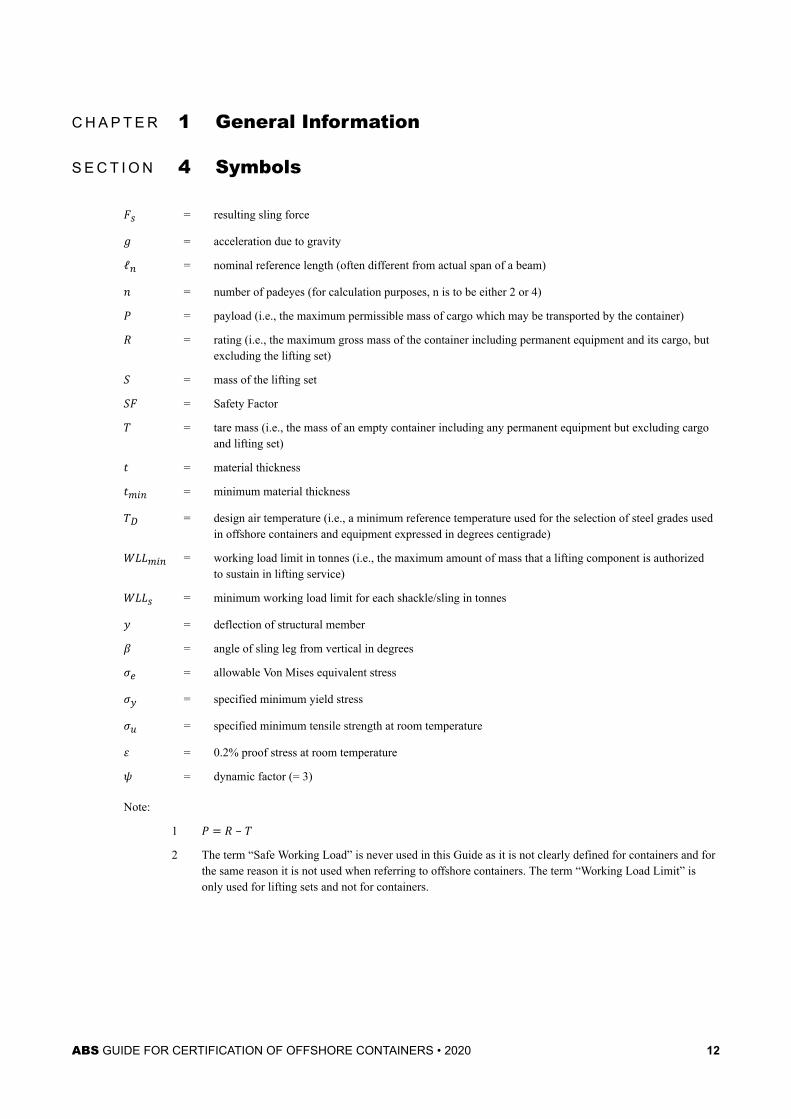
Fs = resulting sling forceg = acceleration due to gravityℓn = nominal reference length (often different from actual span of a beam)n = number of padeyes (for calculation purposes, n is to be either 2 or 4)P = payload (i.e., the maximum permissible mass of cargo which may be transported by the container)R = rating (i.e., the maximum gross mass of the container including permanent equipment and its cargo, butexcluding the lifting set)S = mass of the lifting setSF = Safety FactorT = tare mass (i.e., the mass of an empty container including any permanent equipment but excluding cargoand lifting set)t = material thicknesstmin = minimum material thicknessTD = design air temperature (i.e., a minimum reference temperature used for the selection of steel grades usedin offshore containers and equipment expressed in degrees centigrade)WLLmin = working load limit in tonnes (i.e., the maximum amount of mass that a lifting component is authorizedto sustain in lifting service)WLLs = minimum working load limit for each shackle/sling in tonnesy = deflection of structural memberβ = angle of sling leg from vertical in degreesσe = allowable Von Mises equivalent stressσy = specified minimum yield stressσu = specified minimum tensile strength at room temperatureε = 0.2% proof stress at room temperatureψ = dynamic factor (= 3)
Note:
1 P = R – T2 The term “Safe Working Load” is never used in this Guide as it is not clearly defined for containers and for
the same reason it is not used when referring to offshore containers. The term “Working Load Limit” isonly used for lifting sets and not for containers.
ABS GUIDE FOR CERTIFICATION OF OFFSHORE CONTAINERS • 2020 12
C H A P T E R 1 General Information
S E C T I O N 5 Quality Assessment
1 GeneralIn general, the ABS Quality Assessment will consist of a review of the Quality Manual and audit of thefacility to verify manufacturing is being performed in accordance with the manual.
The quality assessment will consist of:
i) Contract or application
ii) Quality Manual review
iii) Quality Plan review
iv) Management assessment
v) Production assessment
vi) Certification
2 Quality ManualThe purpose of the Quality Manual is to describe the scope and extent of the company’s quality system in aconcise and brief format.
The company is to establish and maintain a quality manual that includes but is not limited to,
i) The scope of quality management system, including details of and justification for any exclusions
ii) The documented procedures established for the quality management system, or reference to them
iii) A description of the interaction between the various processes within the quality managementsystem
The Quality Manual to be submitted to ABS for review and approval prior to requesting an initialassessment. Where a recognized certification body has approved the Quality Manual, ABS will not requirethe manual to be submitted to ABS for review. The Quality Manual is to be available for the ABSSurveyor to assess the performance of the quality system in place at the manufacturing facility.
3 Quality Plan (1 February 2020)A typical Quality Plan is to describe methods of assuring and controlling quality during production as maybe required by the product specifications and will be subject to review by ABS. In particular, the QualityPlan is to reflect specific inspections, tests, etc., required by the Rules, Guides, regulations and standards.The manufacturer is to present a representative sample of the product “type” to the Surveyor for thepurpose of verifying that the “type” has been manufactured in conformance with the design documents.
Prior to the assessment, the manufacturer is to submit the Quality Plan to the Surveyor.
The plan is to include but not to be limited to the following:
● Issuance of material specification for purchasing
● Receiving inspection of materials
● Receiving inspection of finished components and parts
● Calibration certification
ABS GUIDE FOR CERTIFICATION OF OFFSHORE CONTAINERS • 2020 13
● Dimensional and functional checks on finished components and parts
● Edge preparation and fit-up tolerances
● Welding procedure qualifications
● Welder qualification
● Welding defect tracking
● NDT written procedures and qualification documentation
● NDT plan
● Casting and weld defect resolutions
● Assembly and fit specifications
● Subassembly inspection: alignment and dimensional checks, functional tests
● Testing of safety devices
● Hydrostatic testing plan
● Factory acceptance test plan
● Identification of dropped object prevention features (if applicable)
4 Quality AssessmentAn assessment is a systematic and independent examination to determine whether quality, environmental,financial, other management activities and the related results comply with planned arrangements, andwhether these arrangements are implemented effectively and suitable to achieve objectives.
i) Management Assessment. Evaluating the quality assurance and quality control system of themanufacturing facility in order to verify its capability to consistently meet the manufacturer’sspecified level of product quality and satisfy the requirements of the Rules, Guides, regulations orstandards.
ii) Production Assessment. Evaluating the product specific manufacturing process in order to verifythat the manufacture and inspections of the products are established to meet the manufacturer’sspecified level of quality control and, to satisfy the requirements of the Rules, Guides, regulationsor standards.
Items that are periodically renewed which require verification by the ABS Surveyor is to be obtained,verified and attached to the assessment report.
4.1 Initial AssessmentThe manufacturer shall submit an application to ABS requesting an initial assessment. The application areto include a copy of the manufacturer’s Quality Manual which shall be reviewed by ABS prior to the initialassessment at the manufacturer’s location.
The quality assurance system is more comprehensive than the manufacturing process, since it considers allof the factors that affect the process. The system includes, but is not limited to, the following:
● Design Assessment
● Quality Manual
● Quality Plan
● Control of process inputs
● Process controlling factors (e.g., competency of personnel, procedures, facilities and equipment,training, etc.)
Chapter 1 General InformationSection 5 Quality Assessment 1-5
ABS GUIDE FOR CERTIFICATION OF OFFSHORE CONTAINERS • 2020 14
● Process outputs
● Measurements of quality
● Process and product for continual improvement
● Control of contracted vendors, service providers, and suppliers.
4.2 Annual AssessmentThe manufacturer must be able to produce records of the products continued compliance with the standard.
Calibration certificates for each piece of equipment used in the production of the container are to becollected during the annual quality assessment and retained as part of the endorsement.
4.3 Renewal AssessmentThe manufacturer shall submit an application to ABS for renewal of an existing quality assessment at least90 days prior to the expiration date of the current quality Factory Approval Certificate. Where for apractical reason the renewal process of the Factory Approval Certificate cannot be completed before theexpiration date of the current certificate, a short-term extension may be considered upon application. Whenthe certificate is renewed within 90 days of the expiration date, the new certificate shall be valid for fiveyears from the expiration of the previous certificate.
The renewal assessment is to be no less detailed than an initial or annual assessment.
During the renewal process, the ABS Surveyor shall verify the following:
● There have been no changes to the design
● The design assessment indicates the most current Rules, Guides, regulations and standards.
● The Quality Plan remains effective to control quality during production.
4.4 Quality Assessment ReportThe applicant is expected to acknowledge any comments or observations. The applicant is expected to takecorrective action on all non-conformances and the conditions found. Corrective actions are to be detailedin the auditor’s report.
4.4.1 Findings, Non-Conformances and Observationsi) Finding. A statement of fact supported by objective evidence about a process whose
performance characteristics meet the definition of non-conformance or observation.
ii) Non-Conformance. A non-conformance is the identification of a non-fulfillment of aspecified requirement.
iii) Observation. An observation is a statement of fact made during a system audit andsubstantiated by objective evidence. It may also be a statement made by the auditorreferring to a situation within the Management System which, if not corrected, may leadto a nonconformity in the future. Therefore, in all subsequent audits, previousobservations are to be reviewed to determine if they have become non-conformities.
Initial, annual or renewal certification is not to be credited if a non-conformance is present. Non-conformances found at initial, annual or renewal assessments must be addressed within 90 days ofthe audits.
4.5 Overdue AssessmentIf an annual or renewal audit is not completed within 90 days after the anniversary date of the FactoryApproval Certificate, all production work is to be inspected for verification of compliance with the latestRules, Guides, regulations or standards.
Chapter 1 General InformationSection 5 Quality Assessment 1-5
ABS GUIDE FOR CERTIFICATION OF OFFSHORE CONTAINERS • 2020 15
5 Factory Approval CertificateThe approval of the factory is based on the assessment outlined above.
5.1 CertificateManufacturing facilities will be issued a Factory Approval Certificate once they are successfully auditedand are found to comply with the following requirements:
i) Have undergone a satisfactory design evaluation
ii) Comply with a quality assurance standard
iii) Have manufacturing quality control that meets the applicable provisions of the Rules, productstandard, or manufacturer’s specification.
5.2 ValidityEach Factory Approval Certificate is valid for 5 years subject to annual endorsements. ABS reserves theright to carry out unscheduled assessments without notice.
The Factory Approval certificate is not transferable and is issued to a unique manufacturer, at a specificaddress, with specific ownership and a specific organization.
Chapter 1 General InformationSection 5 Quality Assessment 1-5
ABS GUIDE FOR CERTIFICATION OF OFFSHORE CONTAINERS • 2020 16
C H A P T E R 1 General Information
S E C T I O N 6 Terms and Conditions
1 Container/Lifting Set Certification ApplicationUnless otherwise agreed in writing, all services rendered and certificates issued in connection withoffshore container and lifting set are governed by the terms and conditions of this Section and the offshorecontainer/lifting set certification application (“Agreement”) specification. By requesting offshorecontainer/lifting set certification, the client agrees to be bound by these terms and conditions.
2 Representations as to CertificationCertification is a representation by ABS as to the structural fitness for a particular use or service inaccordance with its Rules, Guides and standards. The ABS Rules and Guides are not meant as a substitutefor the independent judgment of professional designers, naval architects and marine engineers nor as asubstitute for the quality control procedures of shipbuilders, container manufacturers, steel makers,suppliers, manufacturers, and sellers of marine materials, machinery or equipment. ABS, being a technicalsociety can only act through Surveyors or others who are believed by it to be skilled and competent.
ABS represents solely to the container/lifting set manufacturer, container/lifting set Owner or client ofABS that when certifying it will use due diligence in the development of Rules, Guides and standards andin using normally applied testing standards, procedures and techniques as called for by the Rules, Guides,standards and other criteria of ABS. ABS further represents to the container/lifting set manufacturer,container/lifting set Owner or other client of ABS that its certificates and reports evidence compliance onlywith one or more of the Rules, Guides, standards or other criteria of ABS in accordance with the terms ofsuch certificate or report. Under no circumstances whatsoever are these representations to be deemed torelate to any third party.
3 Suspension of CertificationAny of the following events will cause immediate suspension of the Design Assessment unless a request issubmitted to ABS for a new review and audit.
i) Redesign of the product or products covered by a Design Assessment certificate
ii) Change in production methods
iii) Substantial change in management organization
iv) Substantial change in frequency or curriculum for personnel training
v) Refusing access to ABS personnel for periodic or annual audits
vi) Failure to correct a non-compliance identified during an audit or in service
vii) Failure to pay ABS fees
4 ValidityThe validity, applicability and interpretation of a certificate issued under the terms of or in contemplationof ABS Container Certification are governed by the Rules, Guides and standards of ABS which shallremain the sole judge thereof. Nothing contained in a Design Assessment or Factory Approval Certificateor in any report issued in contemplation of such a Certificate shall be deemed to relieve any designer,builder, owner, manufacturer, seller, supplier, repairer, operator, insurer, or other entity of any duty toinspect or any other duty or warranty express or implied, nor create any interest, right, claim or benefit inany third party. Nothing expressed herein or in any Certificate or report issued under these Rules isintended or shall be construed to give any person, firm or corporation other than the parties hereto, any
ABS GUIDE FOR CERTIFICATION OF OFFSHORE CONTAINERS • 2020 17
right, remedy, or claim hereunder or under any provisions herein contained; all provisions hereof are forthe sole and exclusive benefit of the parties hereto.
5 DisagreementAny disagreement regarding either the proper interpretation of the Guide or translation of the Guide fromthe English language edition is to be referred to ABS for resolution.
6 LimitationABS makes no representations beyond those contained herein and in the provisions of the Agreementregarding its reports, statements, plan review, surveys, certificates or other services. Except as otherwisespecifically set out in this Agreement, neither ABS nor any of its officers, committees, directors,employees, subcontractors, or agents shall be liable for any loss, damage, or expense of whatever type orkind sustained by any person due to any act, omission or error of any nature caused by ABS, its officers,committees, directors, employees, subcontractors, or agents, or due to any inaccuracy of any nature, even ifheld to amount to a breach of warranty.
7 Hold HarmlessClient, or its assignee or successor in interest, agree to release ABS and all ABS officers, directors,employees, subcontractors and agents (collectively “ABS Representatives”), and to indemnify and holdharmless ABS and ABS Representatives against any and all claims, demands, lawsuits, or actions fordamages, including legal fees, to persons and/or property, tangible, intangible, or otherwise which may bebrought against ABS or ABS Representatives incidental to, arising out of or in connection with theAgreement, the work to be done, the services to be provided or material to be furnished under ABScertificates, except for those claims caused solely and completely by the negligence of ABS or ABSRepresentatives.
Any other individual, corporation, partnership, limited liability company, or other entity who in any wayparticipates in, is engaged in connection with or is a beneficiary of, any portion of the services describedherein shall also release ABS and all ABS Representatives and shall indemnify and hold ABS and all ABSRepresentatives harmless from and against all claims, demands, lawsuits or actions for damages, includinglegal fees, to persons and/or property, tangible, intangible or otherwise, which may be brought against ABSor ABS Representatives by any person or entity as a result of the services performed pursuant to thisAgreement, except for those claims caused solely and completely by the negligence of ABS or ABSRepresentatives.
8 ArbitrationAny and all differences and disputes of whatsoever nature arising out of this Agreement shall be put toarbitration in the City of New York pursuant to the laws relating to the arbitration there in force, before aboard of three persons, consisting of one arbitrator to be appointed by ABS, one by Client, and one by thetwo so chosen. The decision of any two of the three on any point or points shall be final. Subject to 1-6/9until such time as the arbitrators finally close the hearings either party shall have the right by written noticeserved on the arbitrators and on an officer of the other party to specify further disputes or difference underthis Agreement for hearing and determination. The arbitration is to be conducted in accordance with therules of the Society of Maritime Arbitrators, Inc. in the English language. The governing law shall be thelaw of the State of New York, U.S.A. The arbitrators may grant any relief which they, or a majority ofthem, deem within the scope of the agreement of the parties, including, but not limited to, specificperformance. Awards made in pursuance to this clause may include costs including a reasonable allowancefor attorney's fees and judgment may be entered upon any award made hereunder in any court havingjurisdiction. ABS and Client hereby mutually waive any and all claims to punitive damages in any forum.
Client shall be required to notify ABS within thirty (30) days of the commencement of any arbitration orany other legal proceeding between it and third parties which may concern ABS’s work in connection with
Chapter 1 General InformationSection 6 Terms and Conditions 1-6
ABS GUIDE FOR CERTIFICATION OF OFFSHORE CONTAINERS • 2020 18
this Agreement and shall afford ABS an opportunity, at ABS’s sole option, to participate in the arbitrationor legal proceeding ling.
9 Time Bar to Legal ActionAny statutes of limitation notwithstanding, Client expressly agrees that its right to bring or to assert againstABS any and all claims, demands or proceedings whether in arbitration or otherwise shall be waivedunless (a) notice is received by ABS within ninety (90) days after Client had notice of or should reasonablyhave been expected to have had notice of the basis for such claims; and (b) arbitration or legal proceedings,if any, based on such claims or demands of whatever nature are commenced within one (1) year of the dateof such notice to ABS.
10 Limitation of LiabilityIf Client, any licensee, subcontractor or anyone claiming through, or in the name of Client relies on anyinformation or advice given by ABS or ABS Representatives and suffers loss, damage or expense directlythereby which is proven to have been caused by the negligent act, omission or error of ABS, ABSRepresentatives or from any breach of any implied or express warranty of workmanlike performance inconnection with the services, or from any other reason, then the combined liability of ABS or ABSRepresentatives to Client or any other person, corporation, partnership, business entity, sovereign, countryor nation, will be limited to the greater of a) $100,000 or b) an amount equal to ten (10) times the sumactually paid for the services alleged to be deficient.
The limitation of liability may be increased up to an amount twenty-five (25) times that sum paid forservices alleged to be deficient upon receipt of Client's written request at or before the time of performanceof those services and upon payment by Client of an additional fee of $10 for every $1,000 increase in theaggregate limitation of liability for all services.
Neither ABS nor ABS Representatives shall in any circumstances be liable for indirect or consequentialloss or damage (including, but without limitation, loss of profit, loss of contract, or loss of use) suffered byany person including Client from any failure by ABS in the performance of its obligations under thisAgreement. Under no circumstances whatsoever shall any individual who may have personally caused theloss, damage or expense be held personally liable.
11 Scope of CertificationNothing contained in any certificate, Design Assessment, Factory Approval, or report is to be deemed torelieve any designer, builder, owner, manufacturer, seller, supplier, repairer, operator, insurer or other entityor person of any duty to inspect or any other duty or warranty, expressed or implied. Any certificate,Design Assessment, Factory Approval, or report evidences only that at the time of the review or audit thematerial, component, product or system, or any other item covered by a certificate, Design Assessment,Factory Approval, or report complied with one or more of the Rules, Guides, standards or other criteria ofABS, or, where there is no ABS standard, complied with the industry or manufacturer’s standard specifiedin the Design Assessment. Any listing or certificate is issued solely for the use of ABS, its committees, itsclients or other authorized entities. Nothing contained in any listing, certificate, Design Assessment,Factory Approval, or report is to be deemed in any way a representation or statement beyond thosecontained herein. ABS is not an insurer or guarantor of the integrity, safety or suitability of a container orof the material, components, products, systems, equipment, machinery and other items incorporated in it.The validity, applicability and interpretation of any certificate, report, plan or document review or approvalare governed by the Rules, Guides, standards or other criteria of ABS who shall remain the sole judgethereof. ABS is not responsible for the consequences arising from the use by other parties of the Rules,Guides, standards or other criteria of ABS, without review, plan approval and survey by ABS.
The term “approved” shall be interpreted to mean that the plans, reports or documents have been reviewedfor compliance with one or more of the Rules, Guides, standards or other criteria acceptable to ABS.
Chapter 1 General InformationSection 6 Terms and Conditions 1-6
ABS GUIDE FOR CERTIFICATION OF OFFSHORE CONTAINERS • 2020 19
12 ConfidentialityAll plans, drawings, specifications and information given to and reports prepared by ABS in connectionwith performance under this Agreement shall be treated as confidential by ABS and shall not be used forany other purposes than those for which furnished without prior written consent, except as may be requiredby judicial order, by governmental order or regulation, by subpoena or by direction of a governmentalagency with subpoena power, by the European Commission, by the flag Administration, or as necessary toenforce any of ABS’s rights hereunder or to defend any claim hereunder. ABS may release specificinformation related to the statutory certification application and status. This information may be publishedon the ABS website or by other media and may include the names, dates and locations of all surveysperformed by ABS, the expiration date of all statutory certificates issued by ABS, transfers, suspensions,withdrawals, cancellations and reinstatements of approval, and other related information as may berequired.
13 EmblemThis Emblem is a representation that will be affixed to each offshore container that meets the criteria ofthis Guide and is certified by ABS
FIGURE 1 Emblem – ABS Offshore Container (ABS OC)
Chapter 1 General InformationSection 6 Terms and Conditions 1-6
ABS GUIDE FOR CERTIFICATION OF OFFSHORE CONTAINERS • 2020 20
C H A P T E R 2 Offshore Containers
CONTENTSSECTION 1 General................................................................................................24
1 Scope............................................................................................242 Offshore Containers......................................................................24
2.1 Offshore Freight Container.............................................. 242.2 Offshore Service Container............................................. 242.3 Offshore Waste Skip........................................................ 24
FIGURE 1 Offshore General Cargo Container...................................... 25
SECTION 2 Materials and Welding....................................................................... 261 General.........................................................................................262 Identification of Materials..............................................................263 Steels............................................................................................26
3.1 Toughness Requirements................................................ 264 Steel Casting in ISO-Corner Fittings.............................................265 Aluminum .....................................................................................276 Non-metallic Materials.................................................................. 287 Material Certificates......................................................................288 Welding.........................................................................................28
8.1 Welding Procedure.......................................................... 298.2 Welding of Primary Structure...........................................298.3 Welding of Secondary Structure...................................... 298.4 Welder/Welder Operator Qualification............................. 29
TABLE 1 Charpy Impact Test – Structural Steel for PrimaryStructural Members..............................................................26
TABLE 2 Aluminum Alloys and Tempers for Rolled Products............. 27TABLE 3 Aluminum Alloys and Tempers for Extruded Products.........28TABLE 4 Documentation of Materials................................................. 28
SECTION 3 Design................................................................................................. 301 General.........................................................................................30
1.1 Structural Design............................................................. 301.2 Stability from Overturning................................................ 301.3 Protection for Protruding Parts........................................ 301.4 Top Protection..................................................................301.5 Intermediate Cargo Decks............................................... 311.6 Design Temperature ( T D )............................................. 311.7 Stacking and Stacking Fittings.........................................31
2 Structural Strength .......................................................................322.1 Lifting with Lifting Set.......................................................32
ABS GUIDE FOR CERTIFICATION OF OFFSHORE CONTAINERS • 2020 21
2.2 Lifting with Forklift Truck.................................................. 322.3 Impact Loads................................................................... 332.4 Padeye Design................................................................ 342.5 Internal Forces on the Container Walls............................35
3 Other Structural Requirements and Construction.........................353.1 Primary Structure.............................................................353.2 Secondary Structure........................................................ 363.3 Additional Structure......................................................... 36
4 Equipment.....................................................................................375 Coating and Corrosion Protection ................................................37
SECTION 4 Prototype Testing...............................................................................381 Test Equipment and Calibration....................................................38
1.1 Test Mass.........................................................................381.2 Calibration........................................................................38
2 Prototype Testing..........................................................................383 Lifting Test.....................................................................................38
3.1 General............................................................................ 383.2 All-point Lifting................................................................. 383.3 Two-point Lifting...............................................................393.4 Post-lifting Test Inspection and Examination of Padeye..39
4 Vertical Impact Test.......................................................................394.1 General............................................................................ 39
5 Other Tests................................................................................... 395.1 Fork lift pockets ...............................................................395.2 Driving Ramps................................................................. 405.3 Stability from Overturning................................................ 40
6 Dangerous Goods Cargo..............................................................40
SECTION 5 Production.......................................................................................... 411 General.........................................................................................412 Primary Structure..........................................................................41
2.1 Examination of Welds...................................................... 413 Secondary Structure.....................................................................424 Production Testing........................................................................ 42
4.1 Lifting Test........................................................................424.2 Weatherproofness Testing............................................... 43
TABLE 1 Nondestructive Examination (NDE) of Structural Welds...... 41TABLE 2 Standards Relevant (NDE) Methods....................................42TABLE 3 NDE Acceptance Criteria..................................................... 42TABLE 4 Number of Containers Required for Lifting Test...................42
ABS GUIDE FOR CERTIFICATION OF OFFSHORE CONTAINERS • 2020 22
SECTION 6 Marking and Data Plate..................................................................... 441 Safety Marking .............................................................................442 Identification Markings .................................................................44
2.1 Container Number........................................................... 443 Information Marking......................................................................444 Marking for Containers with Intermediate Deck ...........................455 Container Data Plate.................................................................... 45
5.1 General............................................................................ 455.2 Contents on the Data Plate..............................................45
TABLE 1 Safety Marking..................................................................... 44TABLE 2 Container Number................................................................44
FIGURE 1 Example of Data Plate Layout..............................................46
ABS GUIDE FOR CERTIFICATION OF OFFSHORE CONTAINERS • 2020 23
C H A P T E R 2 Offshore Containers
S E C T I O N 1 General
1 ScopeThis Chapter specifies the requirements for the design, manufacture and marking of offshore freight, wasteskip and service containers intended for repeated use to, from and between fixed or floating installationsand ships.
2 Offshore ContainersAn offshore container is a portable unit with gross mass not exceeding 25,000 kg (55116 lb) for repeateduse in the transport of goods or equipment handled in open seas to, from and between fixed and/or floatinginstallations and ships.
Offshore containers are subdivided into the following three categories:
2.1 Offshore Freight ContainerOffshore freight containers are offshore containers built for the transport of goods. Examples of offshorecontainers are:
● General Cargo Container. A closed container with doors
● Cargo Basket. An open top container for general or special cargo
● Tank Container. A container for transport of dangerous or non-dangerous fluids
● Multiple Element Gas Containers (MEGCs)
● Bulk Container. A container for the transport of solids in bulk
● Special Container. A container for the transport of special cargo (e.g., garbage containers, equipment)
● Boxes, gas cylinder racks
2.2 Offshore Service ContainerAn offshore service container is an offshore container built and equipped for a special service task, usuallyas a temporary installation (e.g., laboratories, workshops, stores, power plants, control stations).
Offshore service containers on a fixed or floating offshore facilities are to be in accordance with the ABSGuide for Portable Accommodation Modules.
Portable accommodations are considered offshore service containers for the purpose of transit only.
2.3 Offshore Waste SkipAn offshore waste skip is an open or closed offshore container used for the storage and removal of waste.
Note: Normally constructed from flat steel plate forming the load bearing sections of the container, with bracing in theform of steel profiles (e.g., channel or hollow section) fitted horizontally and/or vertically around sides and ends.In addition to the padeyes for the lifting set, these containers may have side mounted lugs suitable for use with thelifting equipment mounted on a skip lift vehicle.
ABS GUIDE FOR CERTIFICATION OF OFFSHORE CONTAINERS • 2020 24
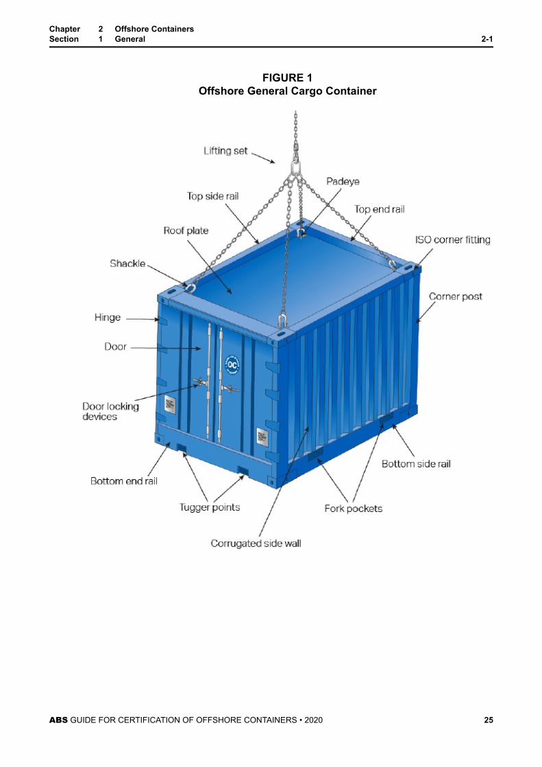
FIGURE 1Offshore General Cargo Container
Chapter 2 Offshore ContainersSection 1 General 2-1
ABS GUIDE FOR CERTIFICATION OF OFFSHORE CONTAINERS • 2020 25
C H A P T E R 2 Offshore Containers
S E C T I O N 2 Materials and Welding
1 GeneralMaterials made of steel are to be suitable for the intended service conditions. They are to be of goodquality, free of defects and are to exhibit satisfactory formability and weldability characteristics. Materialsother than steels are to be specially considered under ABS review.
2 Identification of MaterialsThe manufacturer is to adopt a system for the identification of finished plates, shapes, castings andforgings which will enable the material to be traced to its original heat; and the Surveyor is to be givensufficient documentation such as a Material Test Report (MTR) and a process for verifying the grademarkings and traceability of the material.
3 SteelsStructural steels for the primary structure are to be carbon steel, carbon-manganese steel, carbon-manganese micro-alloyed steel or low-alloyed steel. Rolled (plates, profiles or hollow sections) or forgedor extruded or cast steels are to be produced in accordance with a standard recognized by ABS. Steels inthe primary structure are to be killed and fine grain treated.
Steels with yield strength σy above 500 N/mm2 (51 kgf/mm2, 73 ksi) are not to be used. Where required,steels for welding are to be made by open hearth, electric furnace or the basic oxygen steel process.
Stainless steels are to comply with the requirements of a standard recognized by ABS.
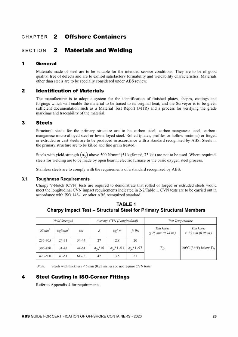
3.1 Toughness RequirementsCharpy V-Notch (CVN) tests are required to demonstrate that rolled or forged or extruded steels wouldmeet the longitudinal CVN impact requirements indicated in 2-2/Table 1. CVN tests are to be carried out inaccordance with ISO 148-1 or other ABS recognized standard.
TABLE 1Charpy Impact Test – Structural Steel for Primary Structural Members
Yield Strength Average CVN (Longitudinal) Test Temperature
N/mm2 kgf/mm2 ksi J kgf-m ft-lbsThickness
≤ 25 mm (0.98 in.)Thickness
> 25 mm (0.98 in.)
235-305 24-31 34-44 27 2.8 20 TD 20°C (36°F) below TD305-420 31-43 44-61 σy/10 σy/1 . 01 σy/1 . 97420-500 43-51 61-73 42 3.5 31
Note: Steels with thickness < 6 mm (0.23 inches) do not require CVN tests.
4 Steel Casting in ISO-Corner FittingsRefer to Appendix 4 for requirements.
ABS GUIDE FOR CERTIFICATION OF OFFSHORE CONTAINERS • 2020 26
5 AluminumThe chemical composition, heat treatment, weldability and mechanical properties are to be suitable for thepurpose.
When materials of different galvanic potential are joined together, the design is to be such that galvaniccorrosion to be avoided.
Aluminum alloys used in offshore containers are to be made by rolling or extruding.
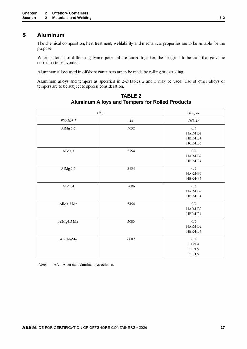
Aluminum alloys and tempers as specified in 2-2/Tables 2 and 3 may be used. Use of other alloys ortempers are to be subject to special consideration.
TABLE 2Aluminum Alloys and Tempers for Rolled Products
Alloy Temper
ISO 209-1 AA ISO/AA
AlMg 2.5 5052 0/0HAR/H32HBR/H34HCR/H36
AlMg 3 5754 0/0HAR/H32HBR/H34
AlMg 3.5 5154 0/0HAR/H32HBR/H34
AlMg 4 5086 0/0HAR/H32HBR/H34
AlMg 3 Mn 5454 0/0HAR/H32HBR/H34
AlMg4.5 Mn 5083 0/0HAR/H32HBR/H34
AlSiMgMn 6082 0/0TB/T4TE/T5TF/T6
Note: AA – American Aluminum Association.
Chapter 2 Offshore ContainersSection 2 Materials and Welding 2-2
ABS GUIDE FOR CERTIFICATION OF OFFSHORE CONTAINERS • 2020 27
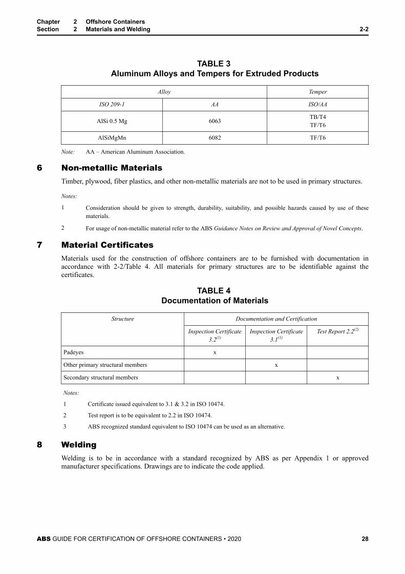
TABLE 3 Aluminum Alloys and Tempers for Extruded Products
Alloy Temper
ISO 209-1 AA ISO/AA
AlSi 0.5 Mg 6063 TB/T4TF/T6
AlSiMgMn 6082 TF/T6
Note: AA – American Aluminum Association.
6 Non-metallic MaterialsTimber, plywood, fiber plastics, and other non-metallic materials are not to be used in primary structures.
Notes:
1 Consideration should be given to strength, durability, suitability, and possible hazards caused by use of thesematerials.
2 For usage of non-metallic material refer to the ABS Guidance Notes on Review and Approval of Novel Concepts.
7 Material CertificatesMaterials used for the construction of offshore containers are to be furnished with documentation inaccordance with 2-2/Table 4. All materials for primary structures are to be identifiable against thecertificates.
TABLE 4 Documentation of Materials
Structure Documentation and Certification
Inspection Certificate3.2(1)
Inspection Certificate3.1(1)
Test Report 2.2(2)
Padeyes x
Other primary structural members x
Secondary structural members x
Notes:
1 Certificate issued equivalent to 3.1 & 3.2 in ISO 10474.
2 Test report is to be equivalent to 2.2 in ISO 10474.
3 ABS recognized standard equivalent to ISO 10474 can be used as an alternative.
8 WeldingWelding is to be in accordance with a standard recognized by ABS as per Appendix 1 or approvedmanufacturer specifications. Drawings are to indicate the code applied.
Chapter 2 Offshore ContainersSection 2 Materials and Welding 2-2
ABS GUIDE FOR CERTIFICATION OF OFFSHORE CONTAINERS • 2020 28
8.1 Welding ProcedureA written Welding Procedure Specification (WPS) is to be prepared in accordance with a standardrecognized by ABS. The WPS and the supporting Procedure Qualification Record (PQR) are to bereviewed and accepted by the attending ABS Surveyor.
Impact tests are required as part of the welding procedure qualification. Test temperatures and test resultsare to comply with the requirements given in 2-2/Table 1.
Welding procedures that are not in accordance with a recognized standard are to be submitted for reviewand approval by ABS Materials Department.
8.2 Welding of Primary StructureAll primary structure is to be welded by full penetration welds.
Non-essential primary structure may be joined by fillet welds with the approval of ABS.
Unwelded primary structures may be accepted by special consideration.
8.3 Welding of Secondary StructureSecondary structure is to be joined by continuous fillet welds including the welding of secondary structureto the primary structure. Intermittent fillet welds may be considered with the approval of ABS.
8.4 Welder/Welder Operator QualificationBefore proceeding with welding, the welder or the welding operator is to be qualified to the intendedwelding procedure. Properly documented Welder Performance Qualification Records (WPQR) conductedin accordance with a recognized welding standard (such as the ASME Boiler and Pressure Vessel Code,Section IX or AWS D1.1) and certified by a recognized body may be presented to the ABS Surveyor foracceptance as evidence of qualification. A qualified welder or welding operator is permitted to performsimilar welding, provided the welding essential variables (e.g., position, with or without backing, pipe size,etc.) are within specified ranges defined by the recognized welding standard being applied.
Chapter 2 Offshore ContainersSection 2 Materials and Welding 2-2
ABS GUIDE FOR CERTIFICATION OF OFFSHORE CONTAINERS • 2020 29
C H A P T E R 2 Offshore Containers
S E C T I O N 3 Design
1 General (1 February 2020)All offshore containers are to be designed and constructed such that they can withstand impact loadsresulting from heavy seas or contact with any structure during transportation. The design is to facilitateloading and unloading operations while the vessel is operating at a maximum wave height of 6 meters (20ft).
Suitable means are to be taken to avoid direct contact of faying surfaces of aluminum to steel.
The designer is responsible for designing the offshore container with sufficient strength to withstand thedesign loads/testing loads and is to include factors of safety allowing for fatigue, normal wear and tear,manufacturing fabrication techniques, and material properties.
1.1 Structural DesignOnly the primary structure as a structural frame is to be considered in design calculations. Specialconsideration to the definition of primary structure may be given to certain types of containers (e.g., wasteskip). Structural design is to be performed in accordance with 2-3/2.
Transition is to be provided for structural continuity to reduce stress concentrations.
1.2 Stability from OverturningOffshore containers are to be designed to withstand an incline of 30° in any direction loaded at itsmaximum gross mass applied at its center of gravity. If the actual center of gravity is not known, themaximum gross mass is to be applied at the half height of the container.
Calculations are to be provided verifying the inclining requirement, alternatively an incline test is to beperformed.
1.3 Protection for Protruding PartsProtruding parts are to be clear from damaging other containers and lifting sets during operations.
Padeyes are to be designed in such a way that they do not protrude outside the boundaries of the containerother than vertically upward, and as far as possible they are to be designed to avoid damage from othercontainers.
1.4 Top Protection (1 February 2020)Open top containers with permanently installed fixtures or equipment and open frame containers are to beprovided with top protection made from a robust material (e.g. plates, grating, GRP, tarpaulin, nets/mesh,webbing).
Top protections are not to be located lower than the lower flange of the top frame members. Fixtures forthe top protection are not to cause snagging hazards.
Top protections can be rigid or flexible. Where possible, the top protection shall cover entire roof of thecontainer; small openings may be incroprated to permit the passage of slings when pad eyes are locatedbelow the protection.
1.4.1 Rigid Top Protections (1 February 2020)Rigid top protections are to have the following characteristics:
ABS GUIDE FOR CERTIFICATION OF OFFSHORE CONTAINERS • 2020 30
● Designed for a uniformly distributed load of 3kN distributed over an area of 600x300 mm(24x12 in).
● Non-slip surface
● Opening size not more than 1,500 mm2 (2 in2)
Examples of rigid top protections are gratings and plates.
1.4.2 Flexible Top Protections (1 February 2020)Flexible top protections are to be designed for a central load of 0.03Rg, but not less than 1kN(2245 lbf) and not more than 3kN (674 lbf), without making contact with internal fittings orequipment.
Examples of flexible top protections are nets/mesh, webbing and tarpaulin.
Note: Nets and webbing are to have an opening size not more than (50 × 50) mm (2 x 2 in).
1.5 Intermediate Cargo DecksWhen intermediate cargo decks are fitted, they are to be designed for the following load, applied uniformlydistributed on the deck:Pi = αPgψwhereα = minimum of 0.5P = payloadg = acceleration due to gravityψ = dynamic factor (= 3)
Intermediate cargo decks are to be designed for a minimum load of half of the total payload (minimum αof 0.5). Values of α other than 0.5 may be modified accordingly.
1.6 Design Temperature (TD)The design temperature (TD) is not to be more than –20°C (–4°F).
When a dedicated service is specified with a lowest daily mean temperature greater than 0°C (32°F), thedesign temperature may be taken as no more than 0°C (32°F). This requirement on design temperature tobe 0°C (32°F) is applicable to regions of temperate climates between 36° North and 36° South and inAustralian waters only. Marking requirements for containers operated in these regions is specified in2-6/3f).
1.7 Stacking and Stacking FittingsOffshore containers are not to be stacked during transportation on ships.
If an offshore freight or service container is intended for stacking on fixed or floating platforms, thecontainer is to be designed for stacking and stacking height is not to exceed two levels. Empty waste skipswith trapezium shaped sides may be designed for stacking at multiple levels.
The stacking guides on the top rails or on the underside of a container are to be designed to prevent lateralmovement under normal operating conditions.
Chapter 2 Offshore ContainersSection 3 Design 2-3
ABS GUIDE FOR CERTIFICATION OF OFFSHORE CONTAINERS • 2020 31
2 Structural StrengthThe structural strength of the containers are to be verified through design calculations and tests asindicated in Chapter 2, Section 4.
2.1 Lifting with Lifting Set2.1.1 Loads
The primary structure is to be analyzed for a total load of 2.5Rg, considering an internal load of(2 . 5R – T)g evenly distributed over the container floor, where:R = rating (i.e., the maximum gross mass of the container including permanent equipment and its cargo,but excluding the lifting set)T = tare mass (i.e., the mass of an empty container including any permanent equipment but excludingcargo and lifting set)g = acceleration due to gravity
For tank containers, the actual distribution of the tare mass is to be used.
2.1.2 CriteriaVon Mises equivalent stress is not to exceed the allowable stress for plate elements, se, obtainedfrom the following equation:σe = 0 . 85CwhereC = σy for steel
= ε for aluminum base material
= 0.7Bσu for aluminum heat affected zoneσy = specified minimum yield stressβ = 0.8 for ISO AIMg4.5Mn-HAR/AA5083-H32
= 0.7 for all other aluminum alloys and tempersσu = specified minimum tensile strength at room temperature
Beam elements are to meet the requirements of a standard recognized by ABS such as AISC.
2.2 Lifting with Forklift Truck2.2.1 Loads (1 February 2020)
The primary structure is to be analyzed for a total load of 1 . 6(R+ S)g, considering an internalload of [1 . 6(R+ S) – T)]g evenly distributed over the container floor. Design force on theprimary structure is to be calculated as 1 . 6(R+ S)g.
whereR , T and g are specified in 2-3/2.1.1.
Where fork pockets are intended only for handling of the empty container, the design load is to betaken as 1 . 6(T+ S)g. Such containers are to be marked in accordance with 2-6 Table 1.
Chapter 2 Offshore ContainersSection 3 Design 2-3
ABS GUIDE FOR CERTIFICATION OF OFFSHORE CONTAINERS • 2020 32
The weight of the lifting set is to be taken into account when the strength of the fork pockets are tobe calculated.
S = mass of the lifting set
2.2.2 CriteriaVon Mises equivalent stress is not to exceed the allowable stress for plate elements, σe, indicatedin 2-3/2.1.2.
Beam elements are to meet the requirements of a standard recognized by ABS such as AISC.
2.3 Impact LoadsImpact loads are dynamic loads of very short duration.
The ability of a container unit to withstand impact loads is to be determined by calculation. Testing is to becarried out to demonstrate that the container can withstand impact loads (refer to 2-4/4).
When simplified calculations are used, each beam is to be considered separately and assumptionsconcerning support conditions are to be stated in the calculations.
2.3.1 Horizontal Impact2.3.1(a) Loads.The primary structure is to be designed to withstand a localized horizontal impact force acting atany point. This force may act in any horizontal direction on the corner post. On all other framemembers in the sides, the load may be considered as acting orthogonal to the side.
The calculated (static equivalent) stress due to impact is to be combined with the lifting stressesresulting from static lifting forces (Rg).The following loads are to be considered for the calculation of the stress due to impact:
● For corner posts and side rails of the bottom structure: –0.25Rg● For other frame members of the side structure, including the top rails: –0.15Rg● For horizontal impact on the tank containers for dangerous cargoes, refer to Appendix 2.R and g are defined in 2-3/2.1.1.
2.3.1(b) Criteria.Maximum calculated deflections at these loadings are not to exceed:
i) For corner posts and bottom side rails: ℓn/250
where is the total length of the rail or post
ii) For other frame members : ℓn /250
where ℓn is the shortest edge of the wall being considered, in mm (in.).
Note: ℓn is a (nominal) reference length and it is often different from actual span of a beam.
For loads indicated in 2-3/2.3.1(a), the von Mises equivalent stress is not to exceed the allowablestress for plate elements σe, obtained from the following equation:σe = C
Chapter 2 Offshore ContainersSection 3 Design 2-3
ABS GUIDE FOR CERTIFICATION OF OFFSHORE CONTAINERS • 2020 33
where C is defined in 2-3/2.1.2.
Beam elements are to meet the requirements of a standard recognized by ABS such as AISC.
2.3.2 Vertical ImpactMaximum vertical impact forces are likely to occur when a container is lowered onto the deck of aheaving supply vessel. If the deck is at an angle, the first impact is likely on a corner. Such impactforces cannot be readily simulated by static forces. Therefore, as an alternative, the strength is tobe verified through vertical impact test as described in with 2-4/4.
In addition the following applies:
2.3.2(a) Loads.The side rails and end rails in the base are to be able to withstand vertical point forces of 0.25Rgat the center span.R and g are defined in 2-3/2.1.1.
2.3.2(b) Criteria.Calculated deflections are not to exceed ( ℓn /250), where ℓn is the total length of the rail.
Von Mises equivalent stress is not to exceed the allowable stress σe, defined in 2-3/2.3.1(b).
Beam elements are to meet the requirements of a standard recognized by ABS such as AISC.
2.4 Padeye Design2.4.1 Loads
Padeyes are to be designed to withstand a total vertical force of 3Rg.
The force is to be considered as distributed uniformly between (n – 1) padeyes, where the valueof ‘n’ is not to exceed 4 and not to be less than 2.
The resulting sling force on each padeye is calculated as follows:Fs = 3Rgn − 1 cosβwhereβ = mass of the lifting setR and g are defined in 2-3/2.1.1.
Containers with only one padeye may be approved by ABS with special consideration. That singlepadeye of the container is to be designed for a total vertical force of 5Rg.
Note: Containers without a roof may have insufficient strength and stiffness to pass the 2 point lifting test, referto 2-4/3.3. Therefore, the open top container is to be analyzed to withstand the load occurring in the 2-point lifting test. In these calculations, the nominal yield stress of the material should not be exceeded.These calculations do not replace the prototype testing.
2.4.2 CriteriaThe maximum concentrated stresses at the hole edge are not to exceed 2σy at design load.
Chapter 2 Offshore ContainersSection 3 Design 2-3
ABS GUIDE FOR CERTIFICATION OF OFFSHORE CONTAINERS • 2020 34
2.5 Internal Forces on the Container WallsThe walls of the containers are to withstand a force of 0.6Pg (60% of the payload) evenly distributed overthe whole surface without experiencing any permanent deformation.
3 Other Structural Requirements and Construction
3.1 Primary Structure3.1.1 Minimum Material Thickness for Primary Structure
The following minimum material thickness (tmin) requirements apply:
i) For external parts of the corner posts and bottom rails (i.e., parts forming the outside ofthe container):
● For R ≥ 1000 kg (2205 lb) tmin= 6 mm (0.24 in.)
● For R < 1000 kg (2205 lb) tmin= 4 mm (0.16 in.)
ii) For all other parts of the primary structure: tmin= 4 mm (0.16 in.)
iii) Waste skips which are designed to utilize the external skin to support most or all of theload:
● tmin = 6 mm (0.24 in.), the area up to 100 mm (4.0 in.) from the side edges.
● tmin= 4 mm (0.16 in.), for the remaining part of the side structure.
whereR = rating (i.e., the maximum gross mass of the container including permanent equipment and its cargo,but excluding the lifting set)tmin = minimum material thickness, in mm (in.)
Note: The thickness may have to be increased beyond these values to take account of special considerationssuch as rating, design, corrosion allowances, the need for impact tests of the material, etc.
3.1.2 PadeyesThe padeyes are to align with the sling to the center of lift, with a maximum manufacturingtolerance of ± 2.5 degrees.
The difference in the diagonal measurements between lifting point centers not to exceed 0.2% ofthe length of the diagonal, or 5 mm (0.2 in.), whichever is the greater.
Clearance between the shackle pin and padeye hole is not to exceed 6% of the nominal shackle pindiameter.
The tolerance between padeye thickness and inside width of shackle are not exceed 25% of theinside width of the shackle.
Padeyes are to be designed as to permit free movement of the shackle and sling terminationwithout fouling the padeye.
Lifting points are to be positioned to minimize the risk of slings fouling against the container or itscargo during operation.
If the lifting force is transferred through the thickness of a plate, plates with specified throughthickness properties in accordance with an ABS recognized standard are to be used.
Chapter 2 Offshore ContainersSection 3 Design 2-3
ABS GUIDE FOR CERTIFICATION OF OFFSHORE CONTAINERS • 2020 35
3.1.3 ISO Corner FittingsRefer to Appendix 4 for requirements.
3.2 Secondary Structure3.2.1 Minimum material thickness
For Secondary structures made from metallic materials, the required minimum material thicknessis:tmin = 2mm 0 . 08in .
3.2.2 FloorsIn the case that there is a possibility that water may collect within the container, provisions are tobe provided for drainage.
3.2.3 Doors and HatchesDoors and hatches, including hinges and securing devices, are to be designed to equivalentenvironmental forces as surrounding structure.
Doors are to be capable of being secured by a locking device in the closed position against thestructural framing of the opening. Each of the double doors are to be secured by a locking deviceagainst the top and bottom structural framing of the opening.
All doors are to be capable to be secured in the open position.
Locking devices are to be secured in such a manner that they do not allow any disengagementduring operations.
3.2.4 Internal Securing PointsContainers for general cargo are to have internal securing points that are designed to withstand aforce of at least 10 kN (1 tf, 2248 lbf).
A secondary securing device is to be provided for all removal parts.
3.3 Additional Structure3.3.1 Fork Lift Pockets
Fork lift pockets may be provided for handling containers in the loaded or unloaded condition.The fork lift pockets are to pass completely through the base structure. Forklift pockets are to haveclosed tops and be provided with means to prevent the container from toppling from the forks.
Fork lift pockets are to meet the following dimensional requirements:
● The minimum internal dimensions of the forklift pockets are to be 200 mm × 90 mm (8 in. ×3.5 in.).
● Forklift Pockets are be located as far apart as practicable but need not be more than 2,050 mm(81 in.) or less than 900 mm (35 in.) apart from center to center of pockets.
Notes:
1 Special requirements apply for fork pockets on tank containers and MEGCs used offshore for the carriagedangerous cargoes, (Refer to Appendix 2).
2 The bottom face of the pocket may be fully closed but it is recommended that openings be provided to facilitatemaintenance and to minimize the risk of loose items being retained in the pockets which could subsequently fallout during lifting operations. These openings should be dimensioned and positioned so as to minimize thelikelihood of the fork tines penetrating or seizing in the opening, or of damaging the free edges at the cut-out.
Chapter 2 Offshore ContainersSection 3 Design 2-3
ABS GUIDE FOR CERTIFICATION OF OFFSHORE CONTAINERS • 2020 36
3 In order to compensate for strength reduction in the bottom side rails in the way of forklift pockets, additionalstrengthening can be placed on the top of the side girders, and it is be in line with the webs of the bottom girder. Itis also required to have full penetration welds on the strengthening members and extend at least 100 mm (4 in.)outside the pocket opening at each end. These strengthening members also serve as protections against the forklifttruck rupturing the side girder.
3.3.2 Tugger PointsTugger points are the attachments to the container that facilitate handling the container withoutlifting. They are to be attached to the primary structure of the container only and are to bepositioned as low on the structure as possible within the outer edges of the container. Tuggerpoints are to be designed to withstand a load equal to the rating of the container.
4 EquipmentSupporting structure of equipment on offshore containers is to be designed for the following factors:
● Dynamic factor: ψ = 3.0
● Safety factor against breaking: SF= 2.0
External connections of the equipment are to be protected from damage.
Note: Certification of equipment is not covered by this Guide.
5 Coating and Corrosion ProtectionCoatings, corrosion protection, paint protection and materials of offshore containers are to be suitable forenvironmental conditions.
All offshore container roofs are to be coated with a permanent non-slip medium.
Chapter 2 Offshore ContainersSection 3 Design 2-3
ABS GUIDE FOR CERTIFICATION OF OFFSHORE CONTAINERS • 2020 37
C H A P T E R 2 Offshore Containers
S E C T I O N 4 Prototype Testing
1 Test Equipment and Calibration
1.1 Test MassCalibrated weights are to be used for verification of the test mass.
1.2 CalibrationCalibration of load cell and hand set are to be carried out annually in accordance with ISO 7500-1 orsimilar national or international standard.
Calibration of test blocks is to be carried out every 24 months to a national or international standard.Measured mass is to be marked on each block.
Calibration certificates for each piece of equipment used in the prototype test of the container are to becollected during attendance and retained as part of the prototype test report.
2 Prototype TestingA container selected for prototype testing is to be representative of the manufacturing process to be usedfor production units. It is to be constructed in conformity with the approved drawings intended forsubsequent production units.
Modifications to the offshore container design require engineering revaluation as per 4-5/2 and mayrequire additional prototype testing.
Test loads are to be uniformly distributed on the container floor, otherwise test loads are to be distributed insuch a way that it represents the actual load distribution in operating conditions.
For offshore containers with additional cargo decks, test loads are to be divided between the floor and theadditional deck in accordance with 2-3/1.5. In the case that the additional deck is detachable, the test loadsare to be placed on the floor.
3 Lifting Test
3.1 GeneralLifting tests are to be carried out with lifting set placed at an angle to the vertical equal to the design angleand held for 5 minutes.
Lifting sets used for the prototype testing of the container are not to be used in service.
Lifting tests are to be carried out carefully at a gradual speed in order to avoid significant acceleration.
3.2 All-point LiftingThe container under test is to be loaded to a total mass of 2.5R and lifted clear off the ground. The test is tobe carried out using all the padeyes and with internal load equal to 2.5R – T.
3.2.1 Acceptance Criteria● During Test: No deflections are to exceed 1/300 of the span of the member.
● After Test: No permanent deformations or other damages are to be observed
ABS GUIDE FOR CERTIFICATION OF OFFSHORE CONTAINERS • 2020 38
3.3 Two-point LiftingThe container under test, is to be loaded to a total mass of 1.5R and lifted clear off the ground. The test isto be carried out using only two diagonally opposite padeyes and with an internal load equal to 1.5R – T.
3.3.1 Acceptance Criteria● After Test: No permanent deformation or other damage is to be observed after testing.
3.4 Post-lifting Test Inspection and Examination of PadeyeNondestructive examination and visual inspection as per 2-5/2.1 of the padeyes, are to be carried out afterthe lifting test.
4 Vertical Impact Test
4.1 GeneralThe containers are to be loaded to their maximum permissible payload (P), and are to be dropped orlowered onto a solid floor. The floor may be covered by wooden planks not exceeding 50 mm (2 in.) inthickness.
The container is to be inclined to form an angle with the floor not less than 5 degrees but in no case is thegreatest vertical distance between the highest point and lowest point of the underside of the containercorners to be more than 400 mm (16 in.).
The corner with lowest rigidity is to be the impacted corner. The corner with lowest rigidity is normally atthe door end for dry cargo container.
One of the following test options are required:
● Option 1 – Drop Test: For drop test, the container is to be suspended from a quick release hook anddropped freely for at least 50 mm (2 in.) for an initial impact of at least one (1) m/s.
● Option 2 – Lowering Test: For lowering test, the container is to be lowered to the floor with aminimum constant speed of 1.5 m/s.
Whenever the container is lowered from a crane, impact speed is to be observed as there is apossibility for the suspending wire and the hook to dampen the free-fall drop speed.
ABS may consider alternative procedures for loading on testing.
4.1.1 Acceptance Criteria● After Test: No major deformation or other damage is to be observed.
5 Other Tests (1 February 2020)
5.1 Fork lift pockets (1 February 2020)Open top containers with an overall length of 6.5 meters (21 ft) or more designated to be lifted by fork liftpockets while loaded, are to be tested with a total uniform distributed gross mass of 1 . 6(R+ S)g andlifted clear of the ground using the fork pockets.
Note: Fork lift pockets testing is not mandatory for other types of containers that have fork lift pockets.
5.1.1 Acceptance Criteria● During Test: No deflections are to exceed 1/300 of the span of the member.
● After Test: No significant deformations or other damages are to be observed after the test iscarried out.
Chapter 2 Offshore ContainersSection 4 Prototype Testing 2-4
ABS GUIDE FOR CERTIFICATION OF OFFSHORE CONTAINERS • 2020 39
5.2 Driving Ramps (1 February 2020)Driving ramps when fitted in offshore containers are to be tested for an axle load of 1.25P, but need not tobe more than 7,260 kg (16,006 lb), evenly distributed between two tires of a test vehicle. Each tire is tohave a surface area not exceeding 142 cm2 (22 in2) with a nominal centre distance of 760 mm (30 in).
If the container is specially designed to transport one or more unit cargoes with a weight (UC) that wouldgive a test axle load higher than 7,260 kg (16,006 lb), the test load is to be 2 times UC. For example, if theunit cargo weighs 6,000 kg (13228 lb), then the test load is to be 2 times 6,000 kg.
Driving ramps are to be clearly marked with the maximum allowable axle load, which shall be 0.8 timesthe test load.
5.3 Stability from Overturning (1 February 2020)Refer to section 2-3/1.2
6 Dangerous Goods CargoContainers intended for the transport of dangerous goods are to be tested in accordance with the IMDGCode and other relevant Rules, regulations and standards as per Appendix 2 of this Guide.
Chapter 2 Offshore ContainersSection 4 Prototype Testing 2-4
ABS GUIDE FOR CERTIFICATION OF OFFSHORE CONTAINERS • 2020 40
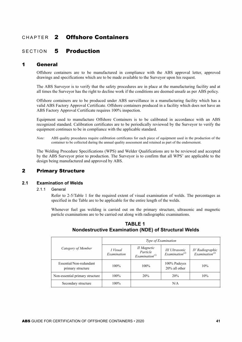
C H A P T E R 2 Offshore Containers
S E C T I O N 5 Production
1 GeneralOffshore containers are to be manufactured in compliance with the ABS approval letter, approveddrawings and specifications which are to be made available to the Surveyor upon his request.
The ABS Surveyor is to verify that the safety procedures are in place at the manufacturing facility and atall times the Surveyor has the right to decline work if the conditions are deemed unsafe as per ABS policy.
Offshore containers are to be produced under ABS surveillance in a manufacturing facility which has avalid ABS Factory Approval Certificate. Offshore containers produced in a facility which does not have anABS Factory Approval Certificate requires 100% inspection.
Equipment used to manufacture Offshore Containers is to be calibrated in accordance with an ABSrecognized standard. Calibration certificates are to be periodically reviewed by the Surveyor to verify theequipment continues to be in compliance with the applicable standard.
Note: ABS quality procedures require calibration certificates for each piece of equipment used in the production of thecontainer to be collected during the annual quality assessment and retained as part of the endorsement.
The Welding Procedure Specifications (WPS) and Welder Qualifications are to be reviewed and acceptedby the ABS Surveyor prior to production. The Surveyor is to confirm that all WPS’ are applicable to thedesign being manufactured and approved by ABS.
2 Primary Structure
2.1 Examination of Welds2.1.1 General
Refer to 2-5/Table 1 for the required extent of visual examination of welds. The percentages asspecified in the Table are to be applicable for the entire length of the welds.
Whenever fuel gas welding is carried out on the primary structure, ultrasonic and magneticparticle examinations are to be carried out along with radiographic examinations.
TABLE 1 Nondestructive Examination (NDE) of Structural Welds
Category of Member
Type of Examination
I VisualExamination
II MagneticParticle
Examination(1)
III UltrasonicExamination(2)
IV RadiographicExamination(2)
Essential/Non-redundantprimary structure 100% 100% 100% Padeyes
20% all other 10%
Non-essential primary structure 100% 20% 20% 10%
Secondary structure 100% N/A
ABS GUIDE FOR CERTIFICATION OF OFFSHORE CONTAINERS • 2020 41
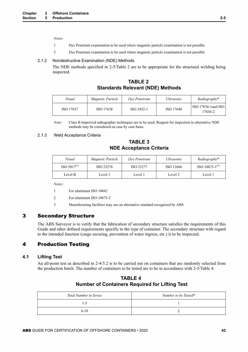
Notes:
1 Dye Penetrant examination to be used where magnetic particle examination is not possible
2 Dye Penetrant examination to be used where magnetic particle examination is not possible
2.1.2 Nondestructive Examination (NDE) MethodsThe NDE methods specified in 2-5/Table 2 are to be appropriate for the structural welding beinginspected.
TABLE 2 Standards Relevant (NDE) Methods
Visual Magnetic Particle Dye Penetrant Ultrasonic Radiography*
ISO 17637 ISO 17638 ISO 3452-1 ISO 17640 ISO 17636-1and ISO17636-2
Note: Class B Improved radiographic techniques are to be used. Request for inspection to alternative NDEmethods may be considered on case by case basis.
2.1.3 Weld Acceptance CriteriaTABLE 3
NDE Acceptance Criteria
Visual Magnetic Particle Dye Penetrant Ultrasonic Radiography*
ISO 5817(1) ISO 23278 ISO 23277 ISO 11666 ISO 10675-1(2)
Level B Level 1 Level 1 Level 2 Level 1
Notes:
1 For aluminum ISO 10042
2 For aluminum ISO 10675-2
3 Manufacturing facilities may use an alternative standard recognized by ABS
3 Secondary StructureThe ABS Surveyor is to verify that the fabrication of secondary structure satisfies the requirements of thisGuide and other defined requirements specific to the type of container. The secondary structure with regardto the intended function (cargo securing, prevention of water ingress, etc.) is to be inspected.
4 Production Testing
4.1 Lifting TestAn all-point test as described in 2-4/3.2 is to be carried out on containers that are randomly selected fromthe production batch. The number of containers to be tested are to be in accordance with 2-5/Table 4.
TABLE 4 Number of Containers Required for Lifting Test
Total Number in Series Number to be Tested*
1-5 1
6-10 2
Chapter 2 Offshore ContainersSection 5 Production 2-5
ABS GUIDE FOR CERTIFICATION OF OFFSHORE CONTAINERS • 2020 42
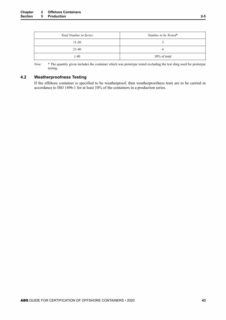
Total Number in Series Number to be Tested*
11-20 3
21-40 4
≥ 40 10% of total
Note: * The quantity given includes the container which was prototype tested excluding the test sling used for prototypetesting.
4.2 Weatherproofness TestingIf the offshore container is specified to be weatherproof, then weatherproofness tests are to be carried inaccordance to ISO 1496-1 for at least 10% of the containers in a production series.
Chapter 2 Offshore ContainersSection 5 Production 2-5
ABS GUIDE FOR CERTIFICATION OF OFFSHORE CONTAINERS • 2020 43
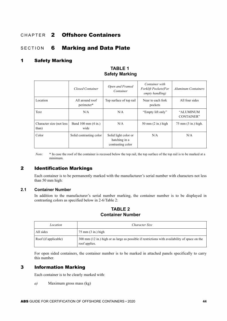
C H A P T E R 2 Offshore Containers
S E C T I O N 6 Marking and Data Plate
1 Safety MarkingTABLE 1
Safety Marking
Closed ContainerOpen and Framed
Container
Container withForklift Pockets(For
empty handling)Aluminum Containers
Location All around roofperimeter*
Top surface of top rail Near to each forkpockets
All four sides
Text N/A N/A “Empty lift only” “ALUMINUMCONTAINER”
Character size (not lessthan)
Band 100 mm (4 in.)wide
N/A 50 mm (2 in.) high 75 mm (3 in.) high.
Color Solid contrasting color Solid light color orhatching in a
contrasting color
N/A N/A
Note: * In case the roof of the container is recessed below the top rail, the top surface of the top rail is to be marked at aminimum.
2 Identification MarkingsEach container is to be permanently marked with the manufacturer’s serial number with characters not lessthan 50 mm high:
2.1 Container NumberIn addition to the manufacturer’s serial number marking, the container number is to be displayed incontrasting colors as specified below in 2-6/Table 2:
TABLE 2Container Number
Location Character Size
All sides 75 mm (3 in.) high
Roof (if applicable) 300 mm (12 in.) high or as large as possible if restrictions with availability of space on theroof applies.
For open sided containers, the container number is to be marked in attached panels specifically to carrythis number.
3 Information MarkingEach container is to be clearly marked with:
a) Maximum gross mass (kg)
ABS GUIDE FOR CERTIFICATION OF OFFSHORE CONTAINERS • 2020 44
b) Tare mass (kg)
c) Payload (kg)
d) Relevant electrical hazard classification and zone marking in accordance with ABS recognizedstandards indicated in Appendix 1/11
e) Relevant dangerous goods placarding in accordance with the IMDG Code. (Refer to Appendix 2for further information)
f) The text “ONLY TO BE USED IN TEMPERATE CLIMATES” displayed on the same side of thedata plate, whenever the containers are operated in temperate climates as specified in 2-3/1.6
a), b) and c) are to be displayed in characters of a contrasting color not less than 50 mm (2 in.) high and f)is to be displayed in characters of a contrasting color not less than 75 mm (3 in.)
Notes:
1 An offshore Container carrying dangerous goods which is taken out of service is to have all dangerous goodsplacarding removed.
2 A matte black panel of appropriate size may be provided for the application of temporary information. It isrecommended that this panel be located on a door, where fitted. Other information (e.g., destination) may be addedif desired.
4 Marking for Containers with Intermediate DeckPayload of the deck is to be displayed on the inside of the container, clearly visible, with characters ofcontrasting colors not less than 50 mm (2 in.) high.
5 Container Data Plate
5.1 GeneralThe container data plate is to be:
● Made of non-corrosive materials
● Attached externally to the doors, although for containers with no doors the data plate may be attachedin a position that it is clear visible place at all times.
● Marked in English language with characters not less than 4 mm high (provision to include additionallanguages may be considered).
Note: Aluminum rivets are not allowed for the attachment of data plates.
5.2 Contents on the Data Plate (1 February 2020)The data plate to be headed:
OFFSHORE CONTAINER DATA PLATE
ABS O.C: YYYY (Where YYYY indicates the latest publication year of ABS OC Guide)
EN 12079 / ISO 10855
The plate is to indicate the following information:
● Manufacturer’s Name
● Manufacturer’s serial number
● Month and year of manufacture
● Maximum gross mass in kilograms excluding lifting set at the design sling angle
Chapter 2 Offshore ContainersSection 6 Marking and Data Plate 2-6
ABS GUIDE FOR CERTIFICATION OF OFFSHORE CONTAINERS • 2020 45
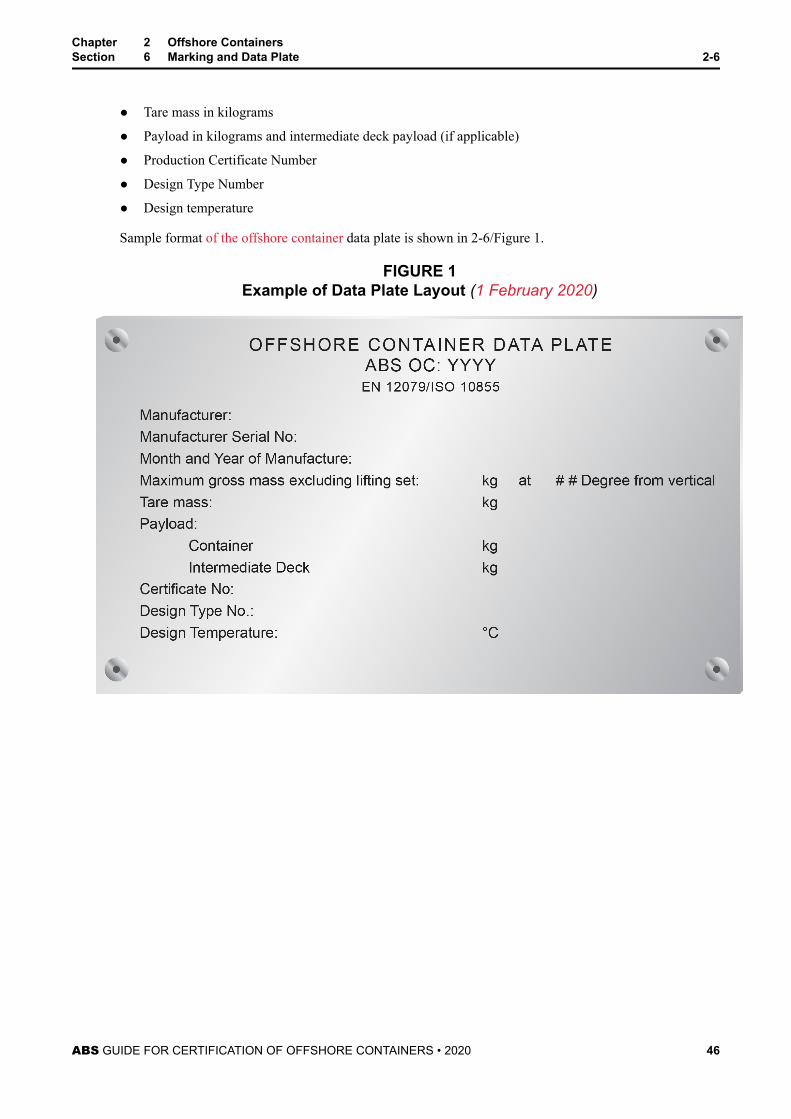
● Tare mass in kilograms
● Payload in kilograms and intermediate deck payload (if applicable)
● Production Certificate Number
● Design Type Number
● Design temperature
Sample format of the offshore container data plate is shown in 2-6/Figure 1.
FIGURE 1Example of Data Plate Layout (1 February 2020)
Chapter 2 Offshore ContainersSection 6 Marking and Data Plate 2-6
ABS GUIDE FOR CERTIFICATION OF OFFSHORE CONTAINERS • 2020 46
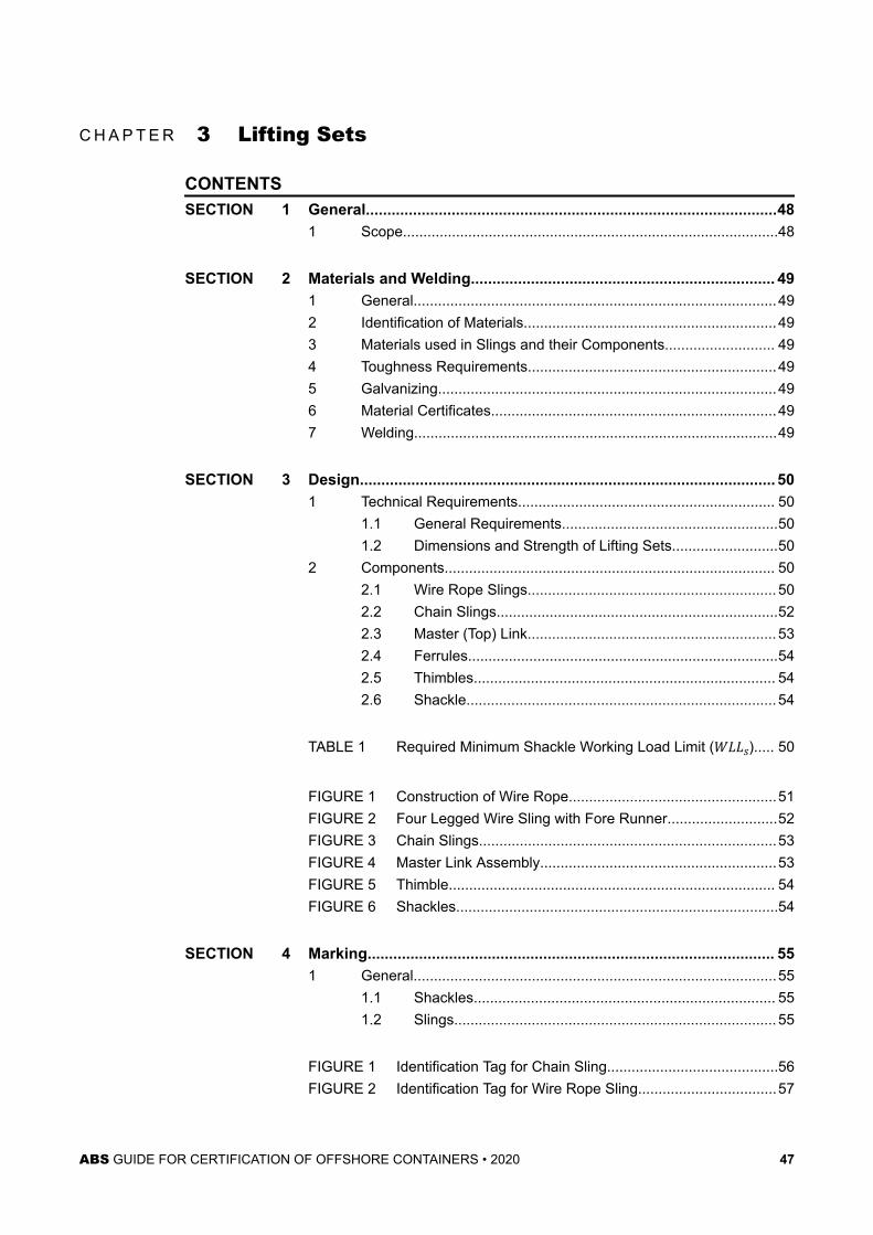
C H A P T E R 3 Lifting Sets
CONTENTSSECTION 1 General................................................................................................48
1 Scope............................................................................................48
SECTION 2 Materials and Welding....................................................................... 491 General.........................................................................................492 Identification of Materials..............................................................493 Materials used in Slings and their Components........................... 494 Toughness Requirements.............................................................495 Galvanizing...................................................................................496 Material Certificates......................................................................497 Welding.........................................................................................49
SECTION 3 Design................................................................................................. 501 Technical Requirements............................................................... 50
1.1 General Requirements.....................................................501.2 Dimensions and Strength of Lifting Sets..........................50
2 Components................................................................................. 502.1 Wire Rope Slings............................................................. 502.2 Chain Slings.....................................................................522.3 Master (Top) Link............................................................. 532.4 Ferrules............................................................................542.5 Thimbles.......................................................................... 542.6 Shackle............................................................................ 54
TABLE 1 Required Minimum Shackle Working Load Limit (WLLs)..... 50
FIGURE 1 Construction of Wire Rope...................................................51FIGURE 2 Four Legged Wire Sling with Fore Runner...........................52FIGURE 3 Chain Slings.........................................................................53FIGURE 4 Master Link Assembly..........................................................53FIGURE 5 Thimble................................................................................ 54FIGURE 6 Shackles...............................................................................54
SECTION 4 Marking............................................................................................... 551 General.........................................................................................55
1.1 Shackles.......................................................................... 551.2 Slings............................................................................... 55
FIGURE 1 Identification Tag for Chain Sling..........................................56FIGURE 2 Identification Tag for Wire Rope Sling..................................57
ABS GUIDE FOR CERTIFICATION OF OFFSHORE CONTAINERS • 2020 47
C H A P T E R 3 Lifting Sets
S E C T I O N 1 General
1 ScopeThe lifting set is to be used on a designated container and is to be with the container at all times. It isremoved only for the purpose of maintenance or replacement. In case, there is a necessity for replacement,the new lifting set is to be manufactured to the original specification and it is also necessary to complywith the requirements of an ABS recognized standard.
Lifting set is to be assembled with components as specified in 1-2/2.1.
The Quality control procedures of the facility that is intended to manufacture the lifting set is required tocomply with requirements specified in 1-5
ABS GUIDE FOR CERTIFICATION OF OFFSHORE CONTAINERS • 2020 48
C H A P T E R 3 Lifting Sets
S E C T I O N 2 Materials and Welding
1 GeneralMaterials are to be suitable for the intended service conditions. The materials used for manufacturing ofthe lifting sets are required to comply with the requirements of an ABS recognized standard and able toresist dynamic loads.
2 Identification of MaterialsThe manufacturer is to adopt a system for the identification of finished plates, shapes, castings andforgings which will enable the material to be traced to its original heat; and the Surveyor is to be givensufficient documentation and means for verifying the traceability of the material.
3 Materials used in Slings and their ComponentsMaterials used in wire ropes, chain slings, ferrules and thimbles are to be in accordance with an ABSrecognized standard.
4 Toughness RequirementsTests are required to demonstrate that steels meet the Charpy V-Notch (CVN) impact requirements inaccordance with ISO 148-1 or an ABS recognized standard.
The CVN requirements are to be attained when tested at the design air temperature (TD) with minimumaverage impact energy of 42 J (4.3 kgf-m, 31 ft-lb). For welded components (chains, links etc.) the test isto be sufficient to take impact test samples in the weld with the notch centered in the fusion line withminimum average impact energy of 27 J (2.8 kgf-m, 20 ft-lb). The position of the weld is to be accuratelyidentified by etching with a suitable reagent before cutting the notches.
When standard specimens cannot be made, the required energy values are to be reduced as follows:
● 10 mm (0.39 in.)×7.5 mm (0.29 in.) : 5/6 of the above value;
● 10 mm (0.39 in.)×5.0 mm (0.19 in.) : 2/3 of the above value.
5 GalvanizingGalvanizing of a component is to be carried out under the control of the manufacturer. Materials forgalvanized structures are to be fabricated and designed in accordance with industry-recommendedpractices.
6 Material CertificatesThe materials used in all components are to be supplied with an inspection certificate in accordance withISO 10474 or similar ABS recognized standard.
7 WeldingBefore undertaking the welding of any structure subject to the requirements of this Guide, a manufactureris to prove to the satisfaction of the Surveyor that the welding consumables and the proposed process areacceptable by ABS and that welders and welding operators are duly qualified for the work intended.
ABS GUIDE FOR CERTIFICATION OF OFFSHORE CONTAINERS • 2020 49
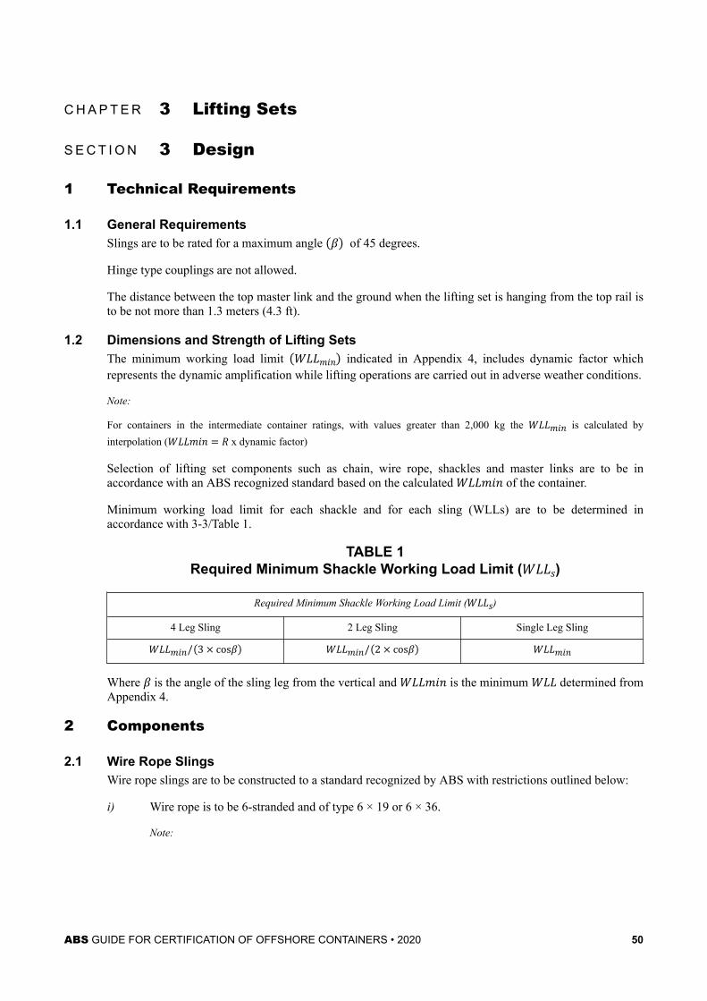
C H A P T E R 3 Lifting Sets
S E C T I O N 3 Design
1 Technical Requirements
1.1 General RequirementsSlings are to be rated for a maximum angle β of 45 degrees.
Hinge type couplings are not allowed.
The distance between the top master link and the ground when the lifting set is hanging from the top rail isto be not more than 1.3 meters (4.3 ft).
1.2 Dimensions and Strength of Lifting SetsThe minimum working load limit WLLmin indicated in Appendix 4, includes dynamic factor whichrepresents the dynamic amplification while lifting operations are carried out in adverse weather conditions.
Note:
For containers in the intermediate container ratings, with values greater than 2,000 kg the WLLmin is calculated byinterpolation (WLLmin = R x dynamic factor)
Selection of lifting set components such as chain, wire rope, shackles and master links are to be inaccordance with an ABS recognized standard based on the calculated WLLmin of the container.
Minimum working load limit for each shackle and for each sling (WLLs) are to be determined inaccordance with 3-3/Table 1.
TABLE 1Required Minimum Shackle Working Load Limit (WLLs)
Required Minimum Shackle Working Load Limit (WLLs)4 Leg Sling 2 Leg Sling Single Leg SlingWLLmin/ 3 × cosβ WLLmin/ 2 × cosβ WLLmin
Where β is the angle of the sling leg from the vertical and WLLmin is the minimum WLL determined fromAppendix 4.
2 Components
2.1 Wire Rope SlingsWire rope slings are to be constructed to a standard recognized by ABS with restrictions outlined below:
i) Wire rope is to be 6-stranded and of type 6 × 19 or 6 × 36.
Note:
ABS GUIDE FOR CERTIFICATION OF OFFSHORE CONTAINERS • 2020 50
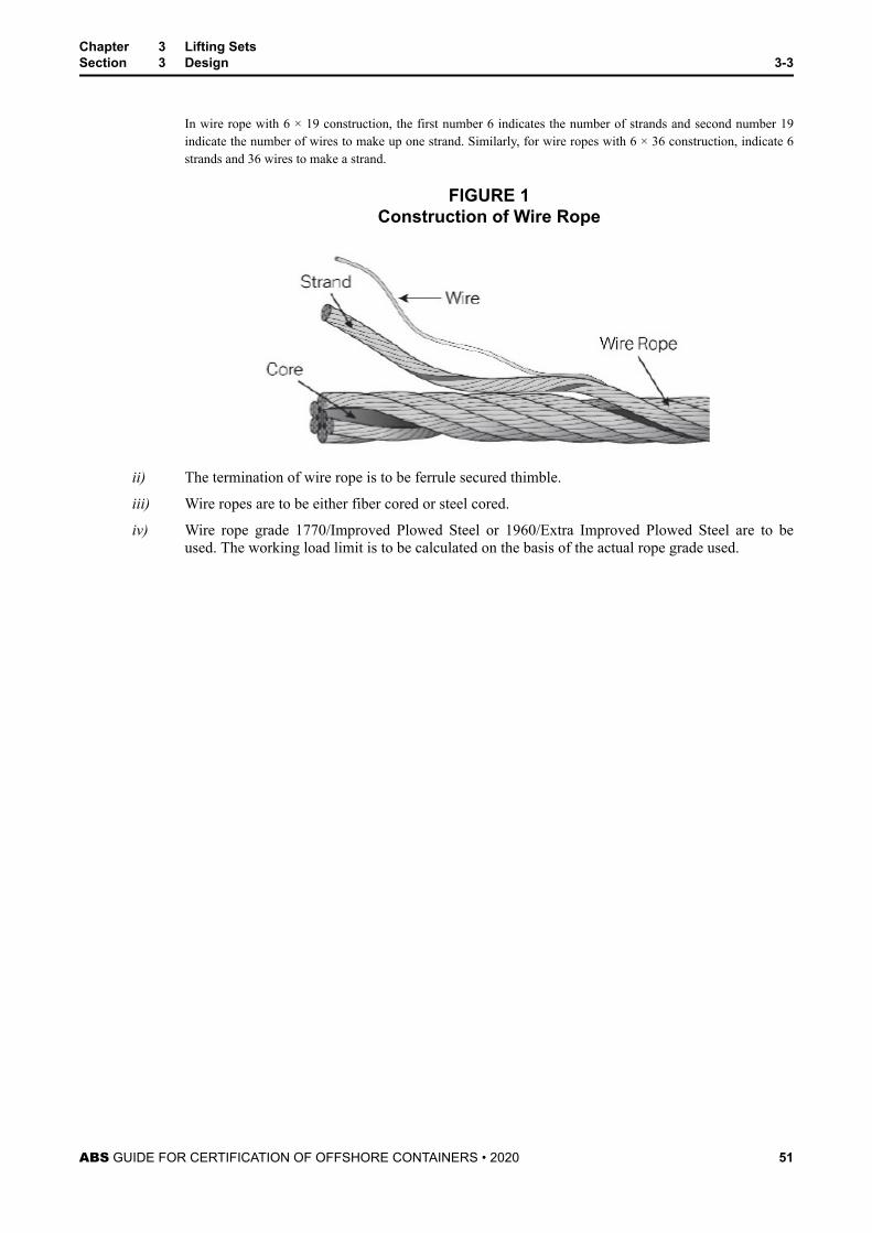
In wire rope with 6 × 19 construction, the first number 6 indicates the number of strands and second number 19indicate the number of wires to make up one strand. Similarly, for wire ropes with 6 × 36 construction, indicate 6strands and 36 wires to make a strand.
FIGURE 1Construction of Wire Rope
ii) The termination of wire rope is to be ferrule secured thimble.
iii) Wire ropes are to be either fiber cored or steel cored.
iv) Wire rope grade 1770/Improved Plowed Steel or 1960/Extra Improved Plowed Steel are to beused. The working load limit is to be calculated on the basis of the actual rope grade used.
Chapter 3 Lifting SetsSection 3 Design 3-3
ABS GUIDE FOR CERTIFICATION OF OFFSHORE CONTAINERS • 2020 51
FIGURE 2 Four Legged Wire Sling with Fore Runner
2.2 Chain SlingsChain slings are to be of Grade 8, and are to meet the requirements of the applicable ABS recognizedstandards. Other grades may be accepted after special consideration by ABS.
Chapter 3 Lifting SetsSection 3 Design 3-3
ABS GUIDE FOR CERTIFICATION OF OFFSHORE CONTAINERS • 2020 52
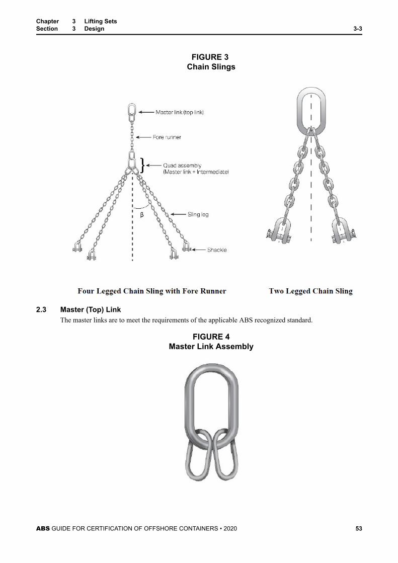
FIGURE 3 Chain Slings
2.3 Master (Top) LinkThe master links are to meet the requirements of the applicable ABS recognized standard.
FIGURE 4Master Link Assembly
Chapter 3 Lifting SetsSection 3 Design 3-3
ABS GUIDE FOR CERTIFICATION OF OFFSHORE CONTAINERS • 2020 53
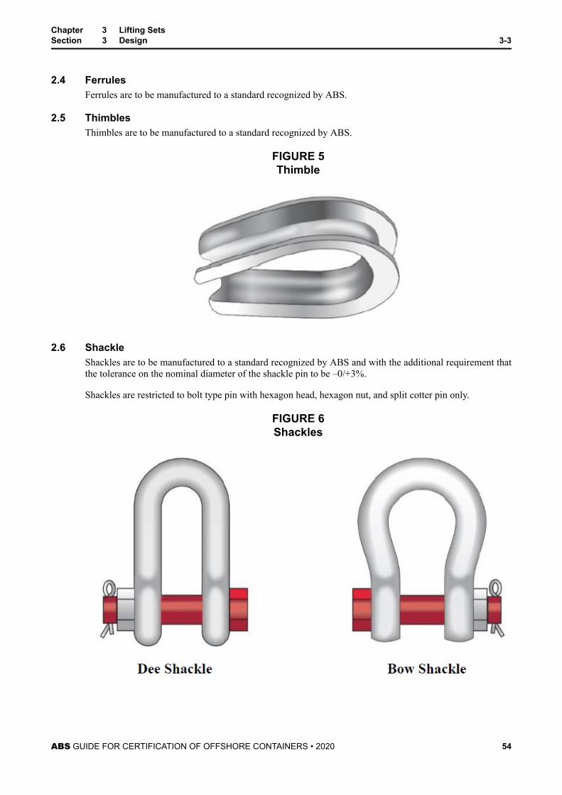
2.4 FerrulesFerrules are to be manufactured to a standard recognized by ABS.
2.5 ThimblesThimbles are to be manufactured to a standard recognized by ABS.
FIGURE 5Thimble
2.6 ShackleShackles are to be manufactured to a standard recognized by ABS and with the additional requirement thatthe tolerance on the nominal diameter of the shackle pin to be –0/+3%.
Shackles are restricted to bolt type pin with hexagon head, hexagon nut, and split cotter pin only.
FIGURE 6Shackles
Chapter 3 Lifting SetsSection 3 Design 3-3
ABS GUIDE FOR CERTIFICATION OF OFFSHORE CONTAINERS • 2020 54
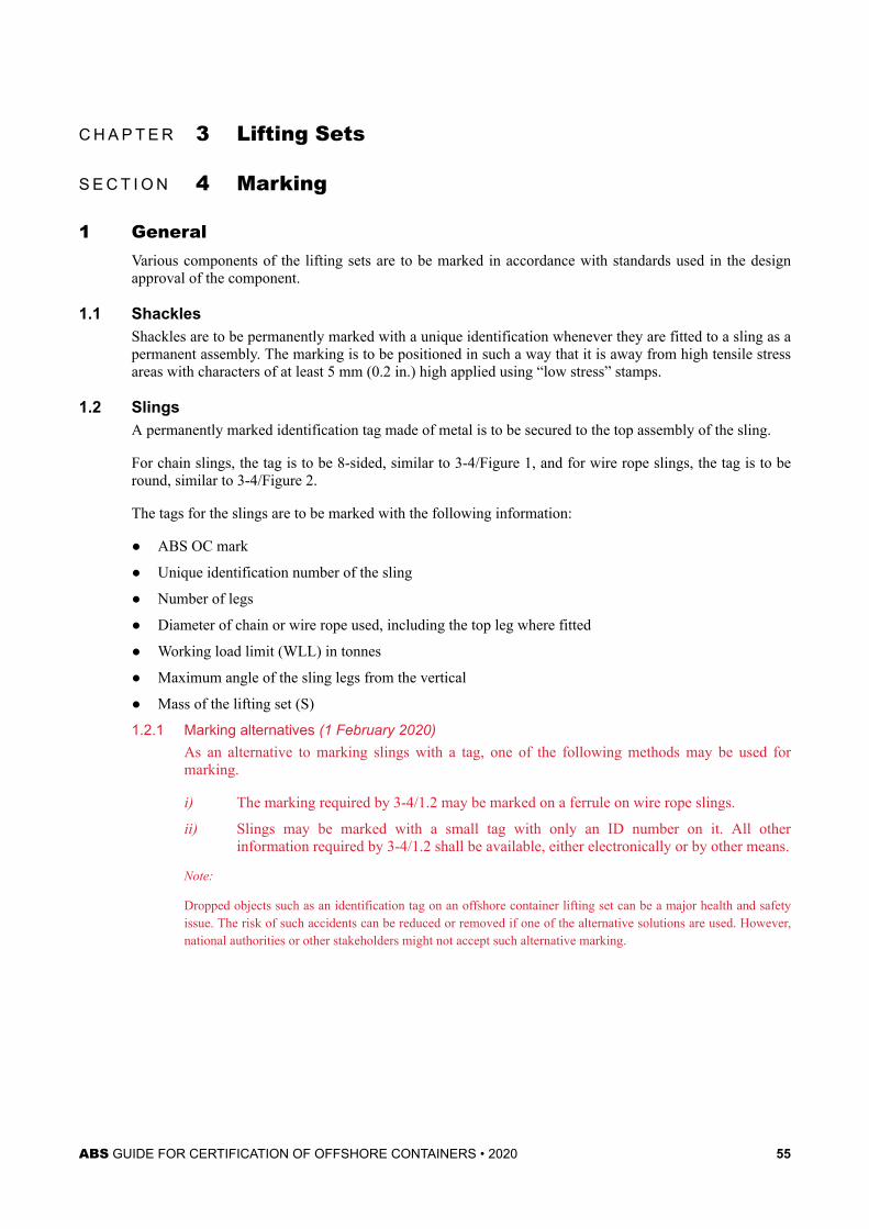
C H A P T E R 3 Lifting Sets
S E C T I O N 4 Marking
1 GeneralVarious components of the lifting sets are to be marked in accordance with standards used in the designapproval of the component.
1.1 ShacklesShackles are to be permanently marked with a unique identification whenever they are fitted to a sling as apermanent assembly. The marking is to be positioned in such a way that it is away from high tensile stressareas with characters of at least 5 mm (0.2 in.) high applied using “low stress” stamps.
1.2 SlingsA permanently marked identification tag made of metal is to be secured to the top assembly of the sling.
For chain slings, the tag is to be 8-sided, similar to 3-4/Figure 1, and for wire rope slings, the tag is to beround, similar to 3-4/Figure 2.
The tags for the slings are to be marked with the following information:
● ABS OC mark
● Unique identification number of the sling
● Number of legs
● Diameter of chain or wire rope used, including the top leg where fitted
● Working load limit (WLL) in tonnes
● Maximum angle of the sling legs from the vertical
● Mass of the lifting set (S)
1.2.1 Marking alternatives (1 February 2020)As an alternative to marking slings with a tag, one of the following methods may be used formarking.
i) The marking required by 3-4/1.2 may be marked on a ferrule on wire rope slings.
ii) Slings may be marked with a small tag with only an ID number on it. All otherinformation required by 3-4/1.2 shall be available, either electronically or by other means.
Note:
Dropped objects such as an identification tag on an offshore container lifting set can be a major health and safetyissue. The risk of such accidents can be reduced or removed if one of the alternative solutions are used. However,national authorities or other stakeholders might not accept such alternative marking.
ABS GUIDE FOR CERTIFICATION OF OFFSHORE CONTAINERS • 2020 55
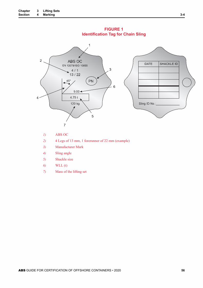
FIGURE 1Identification Tag for Chain Sling
1) ABS OC
2) 4 Legs of 13 mm, 1 forerunner of 22 mm (example)
3) Manufacturer Mark
4) Sling angle
5) Shackle size
6) WLL (t)
7) Mass of the lifting set
Chapter 3 Lifting SetsSection 4 Marking 3-4
ABS GUIDE FOR CERTIFICATION OF OFFSHORE CONTAINERS • 2020 56
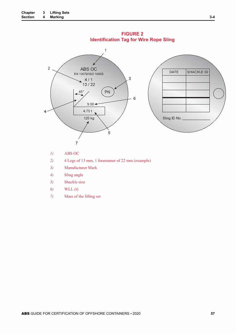
FIGURE 2Identification Tag for Wire Rope Sling
1) ABS OC
2) 4 Legs of 13 mm, 1 forerunner of 22 mm (example)
3) Manufacturer Mark
4) Sling angle
5) Shackle size
6) WLL (t)
7) Mass of the lifting set
Chapter 3 Lifting SetsSection 4 Marking 3-4
ABS GUIDE FOR CERTIFICATION OF OFFSHORE CONTAINERS • 2020 57
C H A P T E R 4 In-Service Inspections
CONTENTSSECTION 1 General................................................................................................59
1 Scope............................................................................................59
SECTION 2 Schedule of Inspections for Offshore Containers.......................... 601 Schedule of Periodic Inspection, Examination and Test –
Offshore Containers......................................................................602 Lifting Test.....................................................................................603 Nondestructive Examination.........................................................604 Visual Inspection...........................................................................60
TABLE 1 Schedule of Inspection, Examination and Tests forOffshore Containers............................................................. 60
SECTION 3 Schedule of Inspections for Lifting Sets......................................... 621 Schedule of Inspection, Examination and Tests – Lifting sets......622 Load Test of Chain Sling Legs......................................................623 Nondestructive Examination of Sling Components except
Wire Rope Legs............................................................................624 Visual Inspection of the Lifting Set................................................62
TABLE 1 Schedule of Periodic Inspection, Examination andTesting of Lifting Sets...........................................................62
SECTION 4 Inspection Plates/Tags...................................................................... 631 Offshore Containers Inspection Plate........................................... 63
1.1 Contents of the Inspection plate...................................... 631.2 Marking............................................................................ 63
2 Inspection Tag for Lifting Set........................................................ 652.1 Marking............................................................................ 65
FIGURE 1 Example of Inspection Plate layout......................................64FIGURE 2 Template of Combined Data Plate and Inspection Plate......65
SECTION 5 Repair and Modification Procedures............................................... 671 Damage and Repair Procedures.................................................. 672 Modification Procedures............................................................... 673 Record Keeping............................................................................67
ABS GUIDE FOR CERTIFICATION OF OFFSHORE CONTAINERS • 2020 58
C H A P T E R 4 In-Service Inspections
S E C T I O N 1 General
1 ScopeThis part of the Guide specifies requirements for the periodic inspection, examination and testing ofoffshore freight, waste skips, and service containers built in accordance with this Guide. Inspectionrequirements following damage and repair of offshore containers are included in 4-5.
ABS requires the container to be periodically inspected, examined and tested in the presence of an ABSSurveyor in accordance with the requirements detailed in Chapter 4, Sections 2 and 3. The ABS Surveyorhas the authority to request additional inspections, examinations and/or tests in order to provide confidencethe container or lifting set is satisfactory for service.
Compliance with the schedule of periodic inspections, examinations and tests for offshore containerscertified to this Guide is the responsibility of the Owner or Operator.
The periodic inspection, examinations or tests may be performed within one (1) month of the test datewithout affecting the schedule of inspection, examination and tests. Any container or lifting set which hasexceed the test date is to be removed from service until the applicable tests have been satisfactorilyperformed to the requirements of this Guide. Containers and lifting sets which are out of test for more thansix (6) months are to be tested in accordance with the test criteria at the four (4) year interval indicated in4-2/Table 1 and 4-3/Table 1.
ABS GUIDE FOR CERTIFICATION OF OFFSHORE CONTAINERS • 2020 59
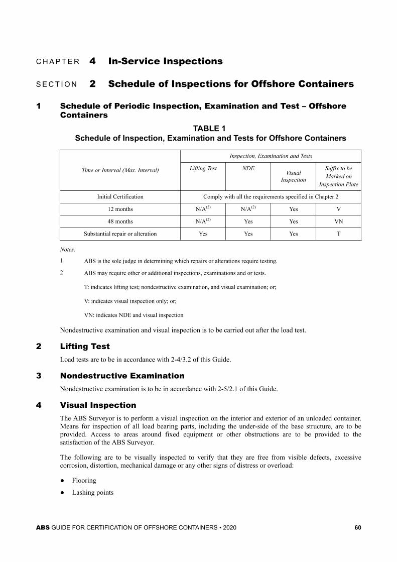
C H A P T E R 4 In-Service Inspections
S E C T I O N 2 Schedule of Inspections for Offshore Containers
1 Schedule of Periodic Inspection, Examination and Test – OffshoreContainers
TABLE 1 Schedule of Inspection, Examination and Tests for Offshore Containers
Time or Interval (Max. Interval)
Inspection, Examination and Tests
Lifting Test NDEVisual
Inspection
Suffix to beMarked on
Inspection Plate
Initial Certification Comply with all the requirements specified in Chapter 2
12 months N/A(2) N/A(2) Yes V
48 months N/A(2) Yes Yes VN
Substantial repair or alteration Yes Yes Yes T
Notes:
1 ABS is the sole judge in determining which repairs or alterations require testing.
2 ABS may require other or additional inspections, examinations and or tests.
T: indicates lifting test; nondestructive examination, and visual examination; or;
V: indicates visual inspection only; or;
VN: indicates NDE and visual inspection
Nondestructive examination and visual inspection is to be carried out after the load test.
2 Lifting TestLoad tests are to be in accordance with 2-4/3.2 of this Guide.
3 Nondestructive ExaminationNondestructive examination is to be in accordance with 2-5/2.1 of this Guide.
4 Visual InspectionThe ABS Surveyor is to perform a visual inspection on the interior and exterior of an unloaded container.Means for inspection of all load bearing parts, including the under-side of the base structure, are to beprovided. Access to areas around fixed equipment or other obstructions are to be provided to thesatisfaction of the ABS Surveyor.
The following are to be visually inspected to verify that they are free from visible defects, excessivecorrosion, distortion, mechanical damage or any other signs of distress or overload:
● Flooring
● Lashing points
ABS GUIDE FOR CERTIFICATION OF OFFSHORE CONTAINERS • 2020 60
● Padeyes
● Structure
● Welds
The above is not a comprhensive list and does not include all possible items.
Additionally, the following are to be visually inspected to verify that they are functioning as intended:
● Door Closures
● Drainage facilities
● Hatches
● Locking devices
● Other appendages
The above is not a comprhensive list and does not include all possible items.
Chapter 4 In-Service InspectionsSection 2 Schedule of Inspections for Offshore Containers 4-2
ABS GUIDE FOR CERTIFICATION OF OFFSHORE CONTAINERS • 2020 61
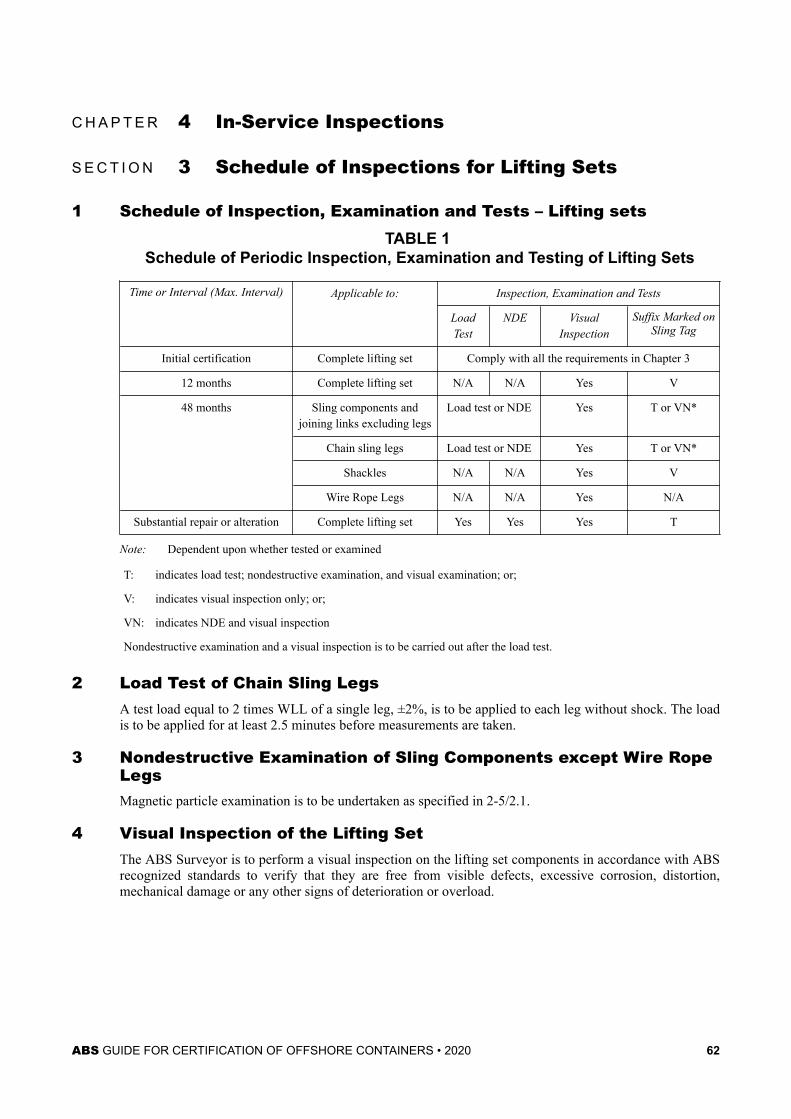
C H A P T E R 4 In-Service Inspections
S E C T I O N 3 Schedule of Inspections for Lifting Sets
1 Schedule of Inspection, Examination and Tests – Lifting setsTABLE 1
Schedule of Periodic Inspection, Examination and Testing of Lifting Sets
Time or Interval (Max. Interval) Applicable to: Inspection, Examination and Tests
LoadTest
NDE VisualInspection
Suffix Marked onSling Tag
Initial certification Complete lifting set Comply with all the requirements in Chapter 3
12 months Complete lifting set N/A N/A Yes V
48 months Sling components andjoining links excluding legs
Load test or NDE Yes T or VN*
Chain sling legs Load test or NDE Yes T or VN*
Shackles N/A N/A Yes V
Wire Rope Legs N/A N/A Yes N/A
Substantial repair or alteration Complete lifting set Yes Yes Yes T
Note: Dependent upon whether tested or examined
T: indicates load test; nondestructive examination, and visual examination; or;
V: indicates visual inspection only; or;
VN: indicates NDE and visual inspection
Nondestructive examination and a visual inspection is to be carried out after the load test.
2 Load Test of Chain Sling LegsA test load equal to 2 times WLL of a single leg, ±2%, is to be applied to each leg without shock. The loadis to be applied for at least 2.5 minutes before measurements are taken.
3 Nondestructive Examination of Sling Components except Wire RopeLegsMagnetic particle examination is to be undertaken as specified in 2-5/2.1.
4 Visual Inspection of the Lifting SetThe ABS Surveyor is to perform a visual inspection on the lifting set components in accordance with ABSrecognized standards to verify that they are free from visible defects, excessive corrosion, distortion,mechanical damage or any other signs of deterioration or overload.
ABS GUIDE FOR CERTIFICATION OF OFFSHORE CONTAINERS • 2020 62
C H A P T E R 4 In-Service Inspections
S E C T I O N 4 Inspection Plates/Tags
1 Offshore Containers Inspection PlateContainers plates are to be fitted with a plate carrying all the information specified in this Section.
The plate is to be as follows:
● Made of non-corrosive material
● Attached externally to the door in a manner to avoid unauthorized or accidental removal (forcontainers with no doors the data plate is to be attached in a clear visible place)
● Marked permanently in English language with characters not less than 4 mm high (additionallanguages may be considered)
Aluminum rivets have been found to be unsuitable as a fixing method in the offshore environment and arenot be used.
1.1 Contents of the Inspection plate (1 February 2020)The containers certified by ABS are to have an Inspection plate that is headed:
OFFSHORE CONTAINER INSPECTION PLATE
ABS O.C:YYYY
EN 12079 / ISO 10855
The plate is to indicate the following information:
● Owner’s container number
● Owner’s name
● Date of last inspection
The date of last inspection is to be the date on which the most recent inspection was carried out to thesatisfaction of the ABS Surveyor.
The date of next inspection is not to be indicated on the data plate. Provision to facilitate permanentmarking to record a minimum of nine inspections is to be provided.
1.2 MarkingUpon satisfactory completion of the inspection, examination and when applicable, test(s), the plate is to bepermanently marked, in accordance with 4-2/Table 1, as follows:
● The date (YYYY-MM-DD) of the inspection, examination, and when applicable, test(s) together withthe unique identification mark of the competent person together with either:
● Suffix T; indicating a lifting test, non-destructive examination and visual inspection; or
● Suffix VN; indicating nondestructive examination, and visual inspection; or
● Suffix V; indicating visual inspection only.
Notes:
ABS GUIDE FOR CERTIFICATION OF OFFSHORE CONTAINERS • 2020 63
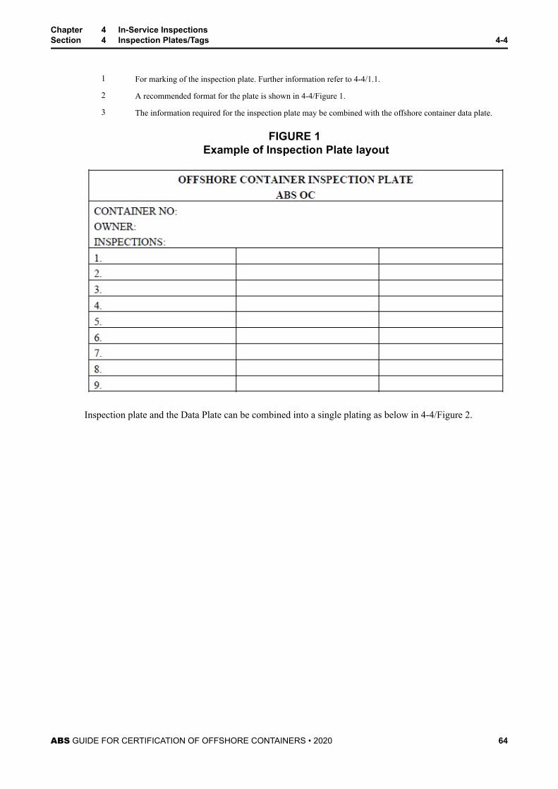
1 For marking of the inspection plate. Further information refer to 4-4/1.1.
2 A recommended format for the plate is shown in 4-4/Figure 1.
3 The information required for the inspection plate may be combined with the offshore container data plate.
FIGURE 1 Example of Inspection Plate layout
Inspection plate and the Data Plate can be combined into a single plating as below in 4-4/Figure 2.
Chapter 4 In-Service InspectionsSection 4 Inspection Plates/Tags 4-4
ABS GUIDE FOR CERTIFICATION OF OFFSHORE CONTAINERS • 2020 64
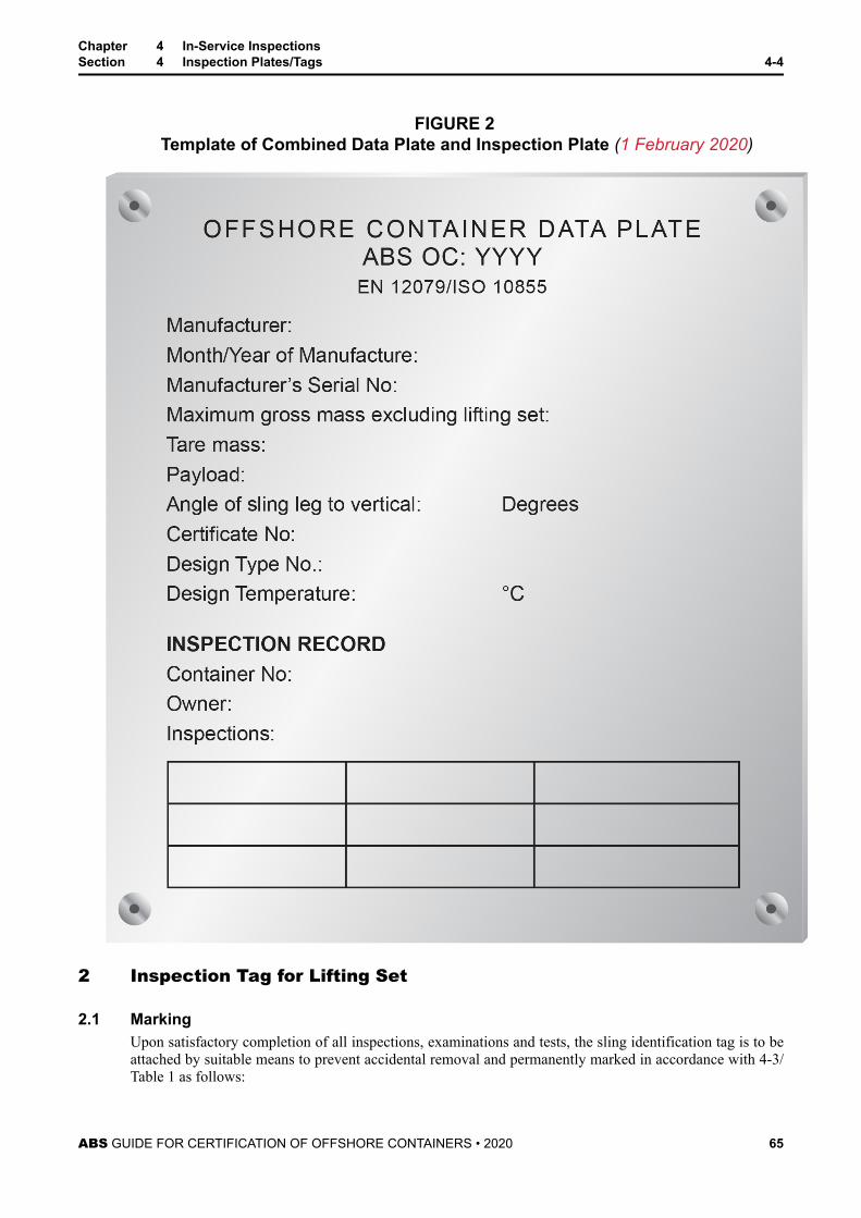
FIGURE 2 Template of Combined Data Plate and Inspection Plate (1 February 2020)
2 Inspection Tag for Lifting Set
2.1 MarkingUpon satisfactory completion of all inspections, examinations and tests, the sling identification tag is to beattached by suitable means to prevent accidental removal and permanently marked in accordance with 4-3/Table 1 as follows:
Chapter 4 In-Service InspectionsSection 4 Inspection Plates/Tags 4-4
ABS GUIDE FOR CERTIFICATION OF OFFSHORE CONTAINERS • 2020 65
● The date YY-MM-DD of the inspection/test, as applicable, together with the unique identificationmark of the ABS together with either:
● Suffix T: indicating load test; nondestructive examination, and visual examination; or
● Suffix V: indicating visual inspection only; or
● Suffix VN: indicating NDE and visual inspection
Chapter 4 In-Service InspectionsSection 4 Inspection Plates/Tags 4-4
ABS GUIDE FOR CERTIFICATION OF OFFSHORE CONTAINERS • 2020 66
C H A P T E R 4 In-Service Inspections
S E C T I O N 5 Repair and Modification Procedures
1 Damage and Repair ProceduresPeriodic inspections are required by this Guide to determine whether damage or wear sustained duringoperation is extensive enough to require the container or lifting set to be repaired or replaced. Damage andwear is generally measured against the original condition. The ABS Surveyor is the sole judge with regardsto certification under this Guide in determining the extent of the damage or wear and whether the containeror lifting set is to be repaired.
A container or lifting set which is considered damaged to the extent that a repair is required, is to beremoved from service until repairs are carried out and inspected by an ABS Surveyor. Means to transportthe container or lifting set are to be arranged which does not include the utilization of the damagedcomponents of the container or lifting set.
The repair facility is to operate under an established quality control system in accordance with therequirements of this Guide. The ABS Surveyor is to review and accept the Welding ProcedureSpecifications (WPS) and Welder Qualifications being used for the repair.
Repairs are to be carried out in accordance with the requirements of this Guide. The damaged or wornareas are to be repaired to their original dimensions and profiles in equivalent grades of material.
The ABS Surveyor is to review all records detailing the repair to verify that the container or lifting set hasbeen repaired to the original condition. The container or lifting set is to be tested and inspected in thepresence of an ABS Surveyor in accordance with 4-2/Table 1 or 4-3/Table 1 of this Guide.
2 Modification ProceduresModifications or revisions to an existing design are to be submitted to ABS in accordance with Chapter 2or Chapter 3 of this Guide.
The facility modifying the container or lifting set is to operate under an established quality control systemin accordance with the requirements of this Guide. The ABS Surveyor is to review and accept the WeldingProcedure Specifications (WPS) and Welder Qualifications being used for the repair.
The ABS Surveyor is to review records detailing the modification to verify if the container or lifting sethas been modified in accordance with the approved drawings. The container or lifting set is to be tested, ifrequired by the ABS approval letter, and inspected in the presence of an ABS Surveyor in accordance withChapter 2 or Chapter 3 of this Guide.
3 Record KeepingThe Owner is to retain all records of approval and inspection for traceability of the container or lifting setduring its life cycle. The records are to include, but are not limited to the following:
● Engineering approval
● Prototype testing certificate
● Production records
● Production certificate
● Records of repair
● Records of modification
ABS GUIDE FOR CERTIFICATION OF OFFSHORE CONTAINERS • 2020 67
● Changes in identification
● Transfer of ownership
All records supporting the certification of the container or lifting set are to be made available to theABS Surveyor upon his request.
Chapter 4 In-Service InspectionsSection 5 Repair and Modification Procedures 4-5
ABS GUIDE FOR CERTIFICATION OF OFFSHORE CONTAINERS • 2020 68
S E C T I O N 1 ABS Recognized Standards
The following list consists of standards which are used in industry and are recognized by ABS. Additionalstandards may be recognized contingent on a review to determine whether the standard is at leastequivalent to that recognized by ABS.
1 Materials
ISO 6892-1 Metallic materials – Tensile testing – Part 1: Method of test at room temperature
ISO 148-1 Metallic materials – Charpy impact test – Part 1: Test method
ISO 10474 Steel and steel products- Inspection documents
EN 10204 Metallic products-Types of inspection documents
EN 10025-1 Hot-rolled products of structural steels – Part 1: General Technical delivery conditions
EN 10025-2 Hot-rolled products of structural steels – Part 2: Technical delivery conditions for non-alloystructural steels
EN 10025-3 Hot-rolled products of structural steels – Part 3: Technical delivery conditions for normalized/normalized rolled weldable fine grain structural steels
EN 10025-4 Hot-rolled products of structural steels – Part 4: Technical delivery conditions for thermomechanical rolled weldable fine grain structural steels
EN 10210-1 Hot finished structural hollow sections of non-alloy and fine grain structural steels. Technicaldelivery requirements
EN 10219-1 Cold formed welded structural sections of non-alloy and fine grain steels. Technical deliveryrequirements
EN 10088-2 Stainless Steels – Part 2: Technical delivery conditions for sheet/plate and strip of corrosionresisting steels for general purposes
ASTM A240/240 M Standard specification for chromium and chromium – nickel stainless steel plate, sheet, and stripfor pressure vessels and for general applications
EN 10250-2 Open die steel forgings for general engineering purposes – Part 2:Non-alloy quality and specialsteels
EN 10250-3 Open die Steel Forgings for General Engineering purposes – Part 3: Alloy special steels
ISO 209-1 Aluminium and Aluminium Alloys – Chemical Composition
2 Quality Control for Manufacturing Facilities
ISO 9001 Quality Management Systems – Requirements
3 ISO Corner Fittings
ISO 1161 Series 1 freight containers – Corner fittings – Specification
ISO 668 Series 1 freight containers – Classification, dimensions and ratings
ABS GUIDE FOR CERTIFICATION OF OFFSHORE CONTAINERS • 2020 69
4 Padeyes
EN 10164 Steel products with improved deformation properties perpendicular to the surface of the product –Technical delivery conditions
5 Welding
EN 9606-1 Qualification test of welders. Fusion welding. Steels
EN ISO 9606-2 Qualification test of welders. Fusion welding-Part 2: Aluminium and Aluminium alloys
ASME ASME Boiler and Pressure Vessel Code, Section IX
AWS D1.1 Structural welding code – Steel
ISO 15607 Specification and qualification of welding procedures for metallic materials – General rules
ISO 15609-1 Specification and qualification of welding procedures for metallic materials – Welding procedurespecification – Part 1: Arc welding
ISO 15614-1 Specification and qualification of welding procedures for metallic materials – Welding proceduretest – Part 1: Arc and gas welding of steels and arc welding of nickel alloys
ISO 15614-2 Specification and qualification of welding procedures for metallic materials – Welding proceduretest – Part 2: Arc welding of Aluminium and its alloys
EN ISO 15613 Specification and qualification of welding procedures for metallic materials – based on pre-production welding test
6 Calibration
EN ISO 7500-1 Metallic materials. Verification of static uniaxial testing machines. Tension/ compression testingmachines. Verification and calibration of the force – measuring system
7 Nondestructive Testing
ISO 17637 Non-destructive testing of welds. Visual testing of fusion –welded joints
ISO 17638 Non-destructive testing of welds. Magnetic particle testing
EN ISO 3452-1 Non-destructive testing. Penetrant testing-Part 1: General Principals
ISO 17640 Non-destructive testing of welds. Ultrasonic testing- techniques, testing levels and assessment
EN ISO 17636-1 Non-destructive testing of welds. Radiographic testing. X- and gamma- ray technique with film
EN ISO 17636-2 Non-destructive testing of welds. Radiographic testing. X- and gamma- ray technique with digitaldetectors
ISO 23278 Non-destructive testing of welds. Magnetic particle testing of welds-Acceptance levels
ISO 23277 Non-destructive examination of welds. Penetrant testing of welds. Acceptance levels
EN ISO 17643 Non-destructive testing of welds. Eddy current testing of welds by complex – plane analysis
EN ISO11666 Non-destructive testing of welds. Ultrasonic testing – Acceptance levels
EN ISO 5817 Welding. Fusion-welded joints in steel, nickel, titanium and their alloys (beam welding excluded).Quality levels for imperfections
ISO 10675-1 Non-destructive testing of welds. Acceptance levels for radiographic testing. Steel, nickel,titanium and their alloys
ISO 10042 Arc-welded joints in aluminum and its alloys – Quality levels for imperfections
Chapter 4 In-Service InspectionsAppendix 1 ABS Recognized Standards 4-A1
ABS GUIDE FOR CERTIFICATION OF OFFSHORE CONTAINERS • 2020 70
ISO 10675-2 Non-destructive testing of welds. Acceptance levels for radiographic testing. aluminum and itsalloys
EN ISO 3834-2 Quality requirements for fusion welding of metallic materials – Part 2: Comprehensive QualityRequirements
ISO 9712 Non-destructive testing. Qualification and certification of NDT personnel
8 Weatherproofness Testing
ISO 1496-1 Series 1 freight containers – Specification and testing – Part 1: General Cargo containers forgeneral purposes
9 Tank Containers
ISO 1496-3 Series 1 freight containers – Specification and testing. Tank containers for liquids, gases andpressurized dry bulk
10 Containers for Bulk Solids
ISO 1496-3 Series 1 freight containers – Specification and testing. Tank containers for liquids, gases andpressurized dry bulk
ISO 1496-4 Series 1 freight container. Specification and testing. Non-pressurized containers for dry bulk
11 Hazardous Areas
ATEX Directive Equipment intended for use in Potentially Explosive Atmospheres
IECEx International Electrotechnical Commission for use in Explosive atmospheres
12 Analysis – Beam Elements
Manual of Steel Construction, AISC, 9th Edition
13 Standards for Lifting Set and their components
ASME B30.9 Slings – Safety Standard for Cableways, Cranes, Derricks, Hoists, Hooks, Jacks, and Slings
ASME B30.26 Rigging Hardware – Safety Standard for Cableways, Cranes, Derricks, Hoists, Hooks, Jacks, andSlings
ISO 898-1 Mechanical properties of fasteners made of carbon steel and alloy steel – Part 1: Bolts, screw andstuds with specified property classes – coarse thread and fine pitch thread
API Spec. 9A Specification for Wire Rope
EN 12385-4 Steel wire ropes. Safety. Stranded ropes for general lifting applications
EN 13411-3 Terminations for steel wire ropes. Safety. Ferrules and ferrule – securing
EN 13411-1 Terminations for steel wire ropes. Safety. Thimbles for steel wire rope slings
EN 818-4 Short link chain for lifting purposes – Safety – Part 4 – Chain slings – Grade 8
EN 818-6 Short link chain for lifting purposes. Safety. Chain slings. Specification for information for useand maintenance to be provided by the manufacturer
EN 1677-1 Components for slings. Safety. Forged steel components, Grade 8
EN 13414-1 Steel wire rope slings. Safety. Slings for general lifting service
Chapter 4 In-Service InspectionsAppendix 1 ABS Recognized Standards 4-A1
ABS GUIDE FOR CERTIFICATION OF OFFSHORE CONTAINERS • 2020 71
EN 13414-2 Steel wire rope slings. Safety. Specification for information for use and maintenance to beprovided by the manufacturer
ABNT NBR 13545 Lifting purposes – Shackles (Brazilian Standard)
ISO 2415 Forged shackles for general lifting purposes – Dee shackles and bow shackles
EN 13889 Forged steel shackles for general lifting purposes. Dee shackles and bow shackles Grade 6. Safety
Chapter 4 In-Service InspectionsAppendix 1 ABS Recognized Standards 4-A1
ABS GUIDE FOR CERTIFICATION OF OFFSHORE CONTAINERS • 2020 72
S E C T I O N 2 Certification Requirements for Offshore TankContainers/Portable Tanks and MEGC
1 Tank Containers for Dangerous GoodsAll tank containers intended for marine transport of dangerous goods are to be certified to the InternationalMaritime Dangerous Goods Code (the IMDG Code). Tank containers built after January 1st 2003 must bebuilt and certified in accordance to the requirements for UN Type tanks (Ch. 6.7 in the IMDG Code). Tankcontainers built before that date may be in accordance with chapter 13 of the older IMDG code (i.e. up toamendment 29 of that code) Tank containers that are certified according to these requirements are alsoallowed for road and rail transport.
1.1 Tank Containers – GeneralIn addition to complying with other relevant design codes and requirements, tank containers are to besuitable for offshore service.
1.2 FrameTank container frames are to be designed to protect the tank/elements and the equipment.
1.3 Tanks for FluidsTanks design are to conform to the relevant sections of ISO 1496-3.
Tanks for dangerous cargoes are to fulfil the requirements of the IMDG Code, and are to be designedaccording to recognized standards such as ISO 1496-3 or to ABS recognized standards. A tank and itssupport are to be able to withstand lifting and impact loads. In addition due account is to be taken of fluidsurge arising from partly filled tanks.
Note: The IMDG Code has restrictions for loaded handling of tanks over a certain length, by forklift. Reference shouldbe made to Chapters 4.2 and 6.7 of the IMDG Code.
1.4 Impact Protection on Tank Containers for Dangerous CargoesAll parts of the tank containers are to be protected from impact damage and in addition to the requirementsof 2-3/2.3 of the Guide, the following requirements apply:
i) Protective covers or housings are to be provided to minimize the risk of damage to the tankcontainers top and its fittings due to impact.
ii) A clearance of at least 100 mm (4 in.) is to be provided between external fittings and the top of thecontainer.
iii) Measures are to be taken to prevent any part of the lifting set from fouling the fittings, manholes,cleats or other protrusions on the tank
iv) Protective beams are to be provided to give necessary protection to the tank shell when the same isnearest to the outer plane of the sides.
v) The residual clearance of at least 10 mm (0.4 in.) is to be provided between the member and anypart of the tank shell or its fittings at the maximum calculated elastic deflection of any sidemember.
ABS GUIDE FOR CERTIFICATION OF OFFSHORE CONTAINERS • 2020 73
vi) The underside of the tank shell (including sumps) and bottom valves or other fittings, are toextend below a level 150 mm (6 in.) above the bottom of the framework (the underside of the sideor end rails). Any such part extending below 300 mm (12 in.) above the bottom of the framework,is to be protected by beams or plating.
Special considerations are to be given to tank containers with direct connections between the tank and theframework.
1.5 Periodic Inspections for Tank ContainersOffshore tank containers that are certified for dangerous goods according to IMDG code are subject to 5year periodic inspections and tests, and to intermediate 2.5 year periodic inspections and tests.
1.6 Multiple Element Gas Containers (MEGCs)Multiple Element Gas Containers are multimodal assemblies of pressure receptacles or elements that areinterconnected by a manifold for filling and discharge which are assembled within an ISO framework andinclude service equipment necessary for the transport of gases. Additional information on this type ofcontainer can be found in the latest edition of ABS Rules for Certification of Cargo Containers.
Chapter 4 In-Service InspectionsAppendix 2 Certification Requirements for Offshore Tank Containers/Portable Tanks and MEGC 4-A2
ABS GUIDE FOR CERTIFICATION OF OFFSHORE CONTAINERS • 2020 74
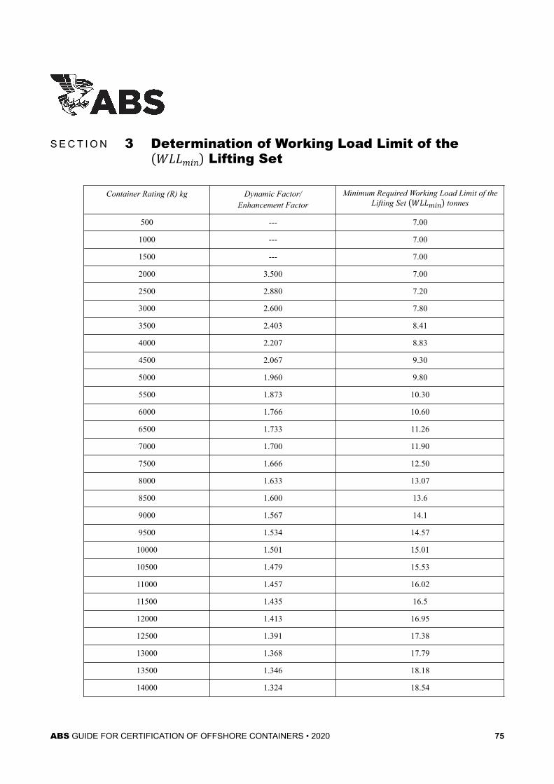
S E C T I O N 3 Determination of Working Load Limit of theWLLmin Lifting Set
Container Rating (R) kg Dynamic Factor/Enhancement Factor
Minimum Required Working Load Limit of theLifting Set WLLmin tonnes
500 --- 7.00
1000 --- 7.00
1500 --- 7.00
2000 3.500 7.00
2500 2.880 7.20
3000 2.600 7.80
3500 2.403 8.41
4000 2.207 8.83
4500 2.067 9.30
5000 1.960 9.80
5500 1.873 10.30
6000 1.766 10.60
6500 1.733 11.26
7000 1.700 11.90
7500 1.666 12.50
8000 1.633 13.07
8500 1.600 13.6
9000 1.567 14.1
9500 1.534 14.57
10000 1.501 15.01
10500 1.479 15.53
11000 1.457 16.02
11500 1.435 16.5
12000 1.413 16.95
12500 1.391 17.38
13000 1.368 17.79
13500 1.346 18.18
14000 1.324 18.54
ABS GUIDE FOR CERTIFICATION OF OFFSHORE CONTAINERS • 2020 75
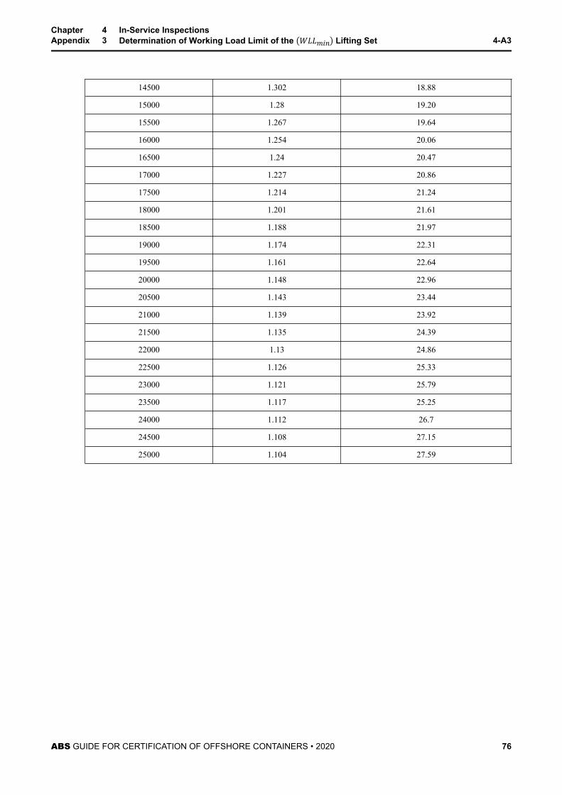
14500 1.302 18.88
15000 1.28 19.20
15500 1.267 19.64
16000 1.254 20.06
16500 1.24 20.47
17000 1.227 20.86
17500 1.214 21.24
18000 1.201 21.61
18500 1.188 21.97
19000 1.174 22.31
19500 1.161 22.64
20000 1.148 22.96
20500 1.143 23.44
21000 1.139 23.92
21500 1.135 24.39
22000 1.13 24.86
22500 1.126 25.33
23000 1.121 25.79
23500 1.117 25.25
24000 1.112 26.7
24500 1.108 27.15
25000 1.104 27.59
Chapter 4 In-Service InspectionsAppendix 3 Determination of Working Load Limit of the WLLmin Lifting Set 4-A3
ABS GUIDE FOR CERTIFICATION OF OFFSHORE CONTAINERS • 2020 76
S E C T I O N 4 Container Corner Castings
1 GeneralContainer corner castings are required to be certified in accordance with the requirements prescribed in thisAppendix. The certification procedure is indicated in Chapter 1, Section 2. Corner fittings are to conformto the requirements of ISO 1161.
Lifting offshore containers with shackles in corner fittings is not acceptable.
Corner fittings of unique design for special purpose containers will also be considered for certificationprovided the strength requirements are not less than those specified by ISO Standard 1161.
Corner castings are to be produced under ABS Surveyor witness in a manufacturing facility which has avalid ABS Factory Approval Certificate (refer to 1-5/5). Corner castings produced in a facility which doesnot have an ABS Factory Approval Certificate will require a certification by heat treatment lot specified inSection 14 of the ABS Rules for Certification of Cargo Containers.
ABS may accept certification of ISO Corner Fittings by other IACS Societies under special considerationsprovided that all the data and supporting document are submitted for review.
Corner fittings are not allowed to carry out lifting operations on offshore containers.
2 Process of ManufactureThe steel is to be made by the open-hearth, electric furnace, or basic oxygen process. Other processes ofmanufacture will be specially considered.
3 Heat TreatmentAll castings are to be either fully annealed, normalized, or normalized and tempered.
4 Material SpecificationsCorner castings are to be made of carbon steel according to the chemical and mechanical properties listedin A4/4.2 and A4/5.3 of this Guide. Other material specifications submitted for certification of cornercastings will be specially considered.
4.1 Chemical AnalysisAn analysis of each heat of steel is to be made by the manufacturer to determine the percentages of theelements specified below. The chemical analysis is to be made from a sample taken during the pouring ofthe heat. If drillings are used from a finished casting, they are to be taken not less than 6 mm (0.24 in.)beneath the surface. The chemical composition thus determined is to conform to the requirementsprescribed in Appendix 4, Table 1 of this Guide. Chemical analysis certificates are to be provided to theSurveyor.
ABS GUIDE FOR CERTIFICATION OF OFFSHORE CONTAINERS • 2020 77
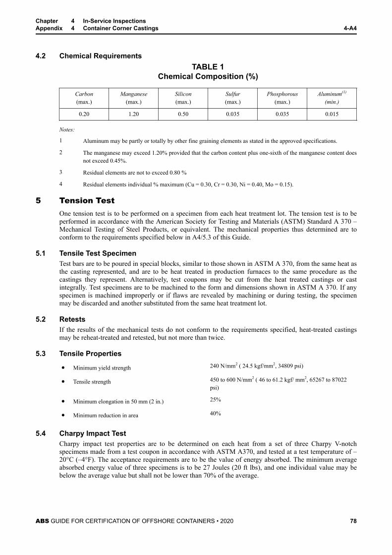
4.2 Chemical RequirementsTABLE 1
Chemical Composition (%)
Carbon(max.)
Manganese(max.)
Silicon(max.)
Sulfur(max.)
Phosphorous(max.)
Aluminum(1)
(min.)
0.20 1.20 0.50 0.035 0.035 0.015
Notes:
1 Aluminum may be partly or totally by other fine graining elements as stated in the approved specifications.
2 The manganese may exceed 1.20% provided that the carbon content plus one-sixth of the manganese content doesnot exceed 0.45%.
3 Residual elements are not to exceed 0.80 %
4 Residual elements individual % maximum (Cu = 0.30, Cr = 0.30, Ni = 0.40, Mo = 0.15).
5 Tension TestOne tension test is to be performed on a specimen from each heat treatment lot. The tension test is to beperformed in accordance with the American Society for Testing and Materials (ASTM) Standard A 370 –Mechanical Testing of Steel Products, or equivalent. The mechanical properties thus determined are toconform to the requirements specified below in A4/5.3 of this Guide.
5.1 Tensile Test SpecimenTest bars are to be poured in special blocks, similar to those shown in ASTM A 370, from the same heat asthe casting represented, and are to be heat treated in production furnaces to the same procedure as thecastings they represent. Alternatively, test coupons may be cut from the heat treated castings or castintegrally. Test specimens are to be machined to the form and dimensions shown in ASTM A 370. If anyspecimen is machined improperly or if flaws are revealed by machining or during testing, the specimenmay be discarded and another substituted from the same heat treatment lot.
5.2 RetestsIf the results of the mechanical tests do not conform to the requirements specified, heat-treated castingsmay be reheat-treated and retested, but not more than twice.
5.3 Tensile Properties
● Minimum yield strength 240 N/mm2 ( 24.5 kgf/mm2, 34809 psi)
● Tensile strength 450 to 600 N/mm2 ( 46 to 61.2 kgf/ mm2, 65267 to 87022psi)
● Minimum elongation in 50 mm (2 in.) 25%
● Minimum reduction in area 40%
5.4 Charpy Impact TestCharpy impact test properties are to be determined on each heat from a set of three Charpy V-notchspecimens made from a test coupon in accordance with ASTM A370, and tested at a test temperature of –20°C (–4°F). The acceptance requirements are to be the value of energy absorbed. The minimum averageabsorbed energy value of three specimens is to be 27 Joules (20 ft lbs), and one individual value may bebelow the average value but shall not be lower than 70% of the average.
Chapter 4 In-Service InspectionsAppendix 4 Container Corner Castings 4-A4
ABS GUIDE FOR CERTIFICATION OF OFFSHORE CONTAINERS • 2020 78
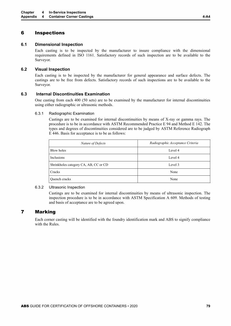
6 Inspections
6.1 Dimensional InspectionEach casting is to be inspected by the manufacturer to insure compliance with the dimensionalrequirements defined in ISO 1161. Satisfactory records of such inspection are to be available to theSurveyor.
6.2 Visual InspectionEach casting is to be inspected by the manufacturer for general appearance and surface defects. Thecastings are to be free from defects. Satisfactory records of such inspections are to be available to theSurveyor.
6.3 Internal Discontinuities ExaminationOne casting from each 400 (50 sets) are to be examined by the manufacturer for internal discontinuitiesusing either radiographic or ultrasonic methods.
6.3.1 Radiographic ExaminationCastings are to be examined for internal discontinuities by means of X-ray or gamma rays. Theprocedure is to be in accordance with ASTM Recommended Practice E 94 and Method E 142. Thetypes and degrees of discontinuities considered are to be judged by ASTM Reference RadiographE 446. Basis for acceptance is to be as follows:
Nature of Defects Radiographic Acceptance Criteria
Blow holes Level 4
Inclusions Level 4
Shrinkholes category CA, AB, CC or CD Level 3
Cracks None
Quench cracks None
6.3.2 Ultrasonic InspectionCastings are to be examined for internal discontinuities by means of ultrasonic inspection. Theinspection procedure is to be in accordance with ASTM Specification A 609. Methods of testingand basis of acceptance are to be agreed upon.
7 MarkingEach corner casting will be identified with the foundry identification mark and ABS to signify compliancewith the Rules.
Chapter 4 In-Service InspectionsAppendix 4 Container Corner Castings 4-A4
ABS GUIDE FOR CERTIFICATION OF OFFSHORE CONTAINERS • 2020 79
S E C T I O N 5 Existing Offshore Containers (15 December 2017)
1 GeneralExisting containers that have not previously been certified by ABS according to the provisions of thisGuide may be considered for certification. Contact the ABS Corporate Container Certification group forcomplete details.
The certification procedure will include general compliance with this guide and as agreed by ABS. Thecertification procedure will include a technical design review, inspection and testing of the existing designprior to issuance of the applicable certification.
This certification process may be applied on a case by case basis for the purpose of bringing existingcontainers into the ABS in-service inspection program per Chapter 4 of this Guide.
2 Marking and Date PlateContainer markings and date plates are to be in accordance with Chapter 2, Section 6 of this Guide.
3 EmblemThis Emblem is a representation that will be affixed to each existing offshore container that meets thecriteria contained in this document and is approved by ABS:
ABS GUIDE FOR CERTIFICATION OF OFFSHORE CONTAINERS • 2020 80