Embed Size (px)
Citation preview

Public Works Standard Specifi cations and
Standard Plans
April 2012
City of City of
Connell, WashingtonConnell, Washington
TABLE OF CONTENTS
04/2012 1 Table of Contents S:\DOCS\CONNELL\W68‐208 WTR SWR ST STNDS\STANDARDS\APRIL 2012\TOC.doc
INTRODUCTION / PURPOSE GENERAL REQUIREMENTS STANDARD SPECIFICATIONS Section 1 – Excavation and Backfill of Trenches .............................. 04/2012 Section 2 – Water Lines ................................................................... 04/2012 Section 3 – Sanitary Sewer Lines ..................................................... 04/2012 Section 4 – Storm Drainage System ................................................. 04/2012 Section 5 – Concrete Curb and Gutter, Sidewalk, ........................... 04/2012 and Driveway Transitions Section 6 – Surface Restoration ....................................................... 04/2012 Section 7 – Road Work ..................................................................... 04/2012 STANDARD PLANS ........................................................................... 04/2012 (See page ii)
04/2012 i Table of Contents S:\DOCS\CONNELL\W68‐208 WTR SWR ST STNDS\STANDARDS\APRIL 2012\STANDARD PLANS TOC.doc
CITY OF CONNELL STANDARD PLANS
TABLE OF CONTENTS
NO. CATEGORY / PLAN GENERAL 1‐1 .......................................... STREET UTILITY LOCATIONS 1‐2 .......................................... MONUMENT CASE AND COVER 1‐3 .......................................... TRENCH EXCAVATION AND BACKFILL 1‐4 .......................................... CONTINUOUS LOCATING WIRE AND IDENTIFYING TAPE 1‐5 .......................................... MINIMUM AIR GAP FOR WATER TRUCKS 1‐6 .......................................... MANHOLE FRAME AND COVER 1‐7 PAGE 1 ............................. STREET SIGN INSTALLATION‐TYPICAL SIGN LOCATION 1‐7 PAGE 2 ............................. STREET SIGN INSTALLATION‐STREET NAME SIGN 1‐7 PAGE 3 ............................. STREET SIGN INSTALLATION‐TYPICAL SIGN POST 1‐8 .......................................... STORM DRAIN INLET PROTECTION STREET 2‐1 .......................................... TRENCH RESTORATION 2‐2 .......................................... UTILITY COVER ADJUSTMENTS 2‐3 .......................................... TYPICAL STREET SECTIONS AND TABLE 2‐4 .......................................... CONCRETE DRIVEWAY AND ALLEY APPROACH 2‐5 .......................................... CONCRETE CURBS AND CURB AND GUTTER 2‐6 .......................................... CONCRETE SIDEWALK 2‐7 PAGE 1 ............................. CONCRETE CURB RAMPS 2‐7 PAGE 2 ............................. CONCRETE CURB RAMPS 2‐8 .......................................... CONCRETE VALLEY GUTTER WATER 3‐1 .......................................... FUTURE MAINLINE EXTENSIONS 3‐2 .......................................... CONNECTION TO EXISTING WATER MAIN 3‐3 PAGE 1 ............................. FIRE HYDRANT AND AUXILIARY VALVE 3‐3 PAGE 2 ............................. FIRE HYDRANT BARRICADE 3‐4 PAGE 1 ............................. THRUST BLOCK SIZING 3‐4 PAGE 2 ............................. THRUST BLOCK REQUIREMENTS AND LOCATIONS 3‐5 .......................................... VALVE BOX 3‐6 .......................................... DOUBLE CHECK VALVE FOR 3/4" TO 2 1/2” WATER SERVICE 3‐7 .......................................... REDUCED PRESSURE BACKFLOW FOR 3/4” AND LARGER WATER SERVICE
TABLE OF CONTENTS (CONT.)
04/2012 ii Table of Contents S:\DOCS\CONNELL\W68‐208 WTR SWR ST STNDS\STANDARDS\APRIL 2012\STANDARD PLANS TOC.doc
WATER (cont.) 3‐8 PAGE 1 ............................. WATER SERVICE CONNECTIONS 3‐8 PAGE 2 ............................. WATER SERVICE LINE FUTURE STUB 3‐9 PAGE 1 ............................. WATER METER INSTALLATION, 2” OR SMALLER 3‐9 PAGE 2 ............................. WATER METER INSTALLATION IN TRAFFIC AREAS 3‐10 PAGE 1 ........................... BLOW‐OFF/FLUSH TYPE HYDRANT
SANITARY SEWER 4‐1 .......................................... SANITARY SEWER CLEANOUT 4‐2 PAGE 1 ............................. MANHOLE BASE AND NOTES 4‐2 PAGE 2 ............................. STANDARD MANHOLE 4‐3 .......................................... MINIMUM WATER/SEWER SEPARATION 4‐4 .......................................... SEWER SERVICE LINE
STORM SEWER 5‐1 PAGE 1 ............................. CATCH BASIN 5‐1 PAGE 2 ............................. CATCH BASIN AND GUTTER INSTALLATION 5‐2 .......................................... CATCH BASIN FRAME 5‐3 .......................................... CATCH BASIN GRATES
INTRODUCTION/PURPOSE
04/2012 S:\DOCS\CONNELL\W68‐208 WTR SWR ST STNDS\STANDARDS\APRIL 2012\INTRO‐PURPOSE.doc
CITY OF CONNELL, WASHINGTON PUBLIC WORKS STANDARDS
INTRODUCTION / PURPOSE These City of Connell Public Works Standards, Standard Specifications, and City of Connell Standard Plans have been prepared by City Staff and Anderson Perry & Associates, Inc., under authorization of the City Council. The standards are intended to establish the requirements for designing, building, and modifying infrastructure that is or will be owned and maintained by the City. The City engineers, developers, contractors, homeowners, and others engaged in the construction or repairs of the City facilities shall comply with the requirements of the document. All users of these documents shall incorporate the requirements into the specific project for which they will be used. Plans and specifications shall be stamped and signed by the responsible Engineer and shall be submitted to the City for review prior to their use on a project within the City.
GENERAL REQUIREMENTS
GENERAL REQUIREMENTS
TABLE OF CONTENTS
04/2012 i Table of Contents S:\DOCS\CONNELL\W68‐208 WTR SWR ST STNDS\STANDARDS\APRIL 2012\GEN REQ.doc
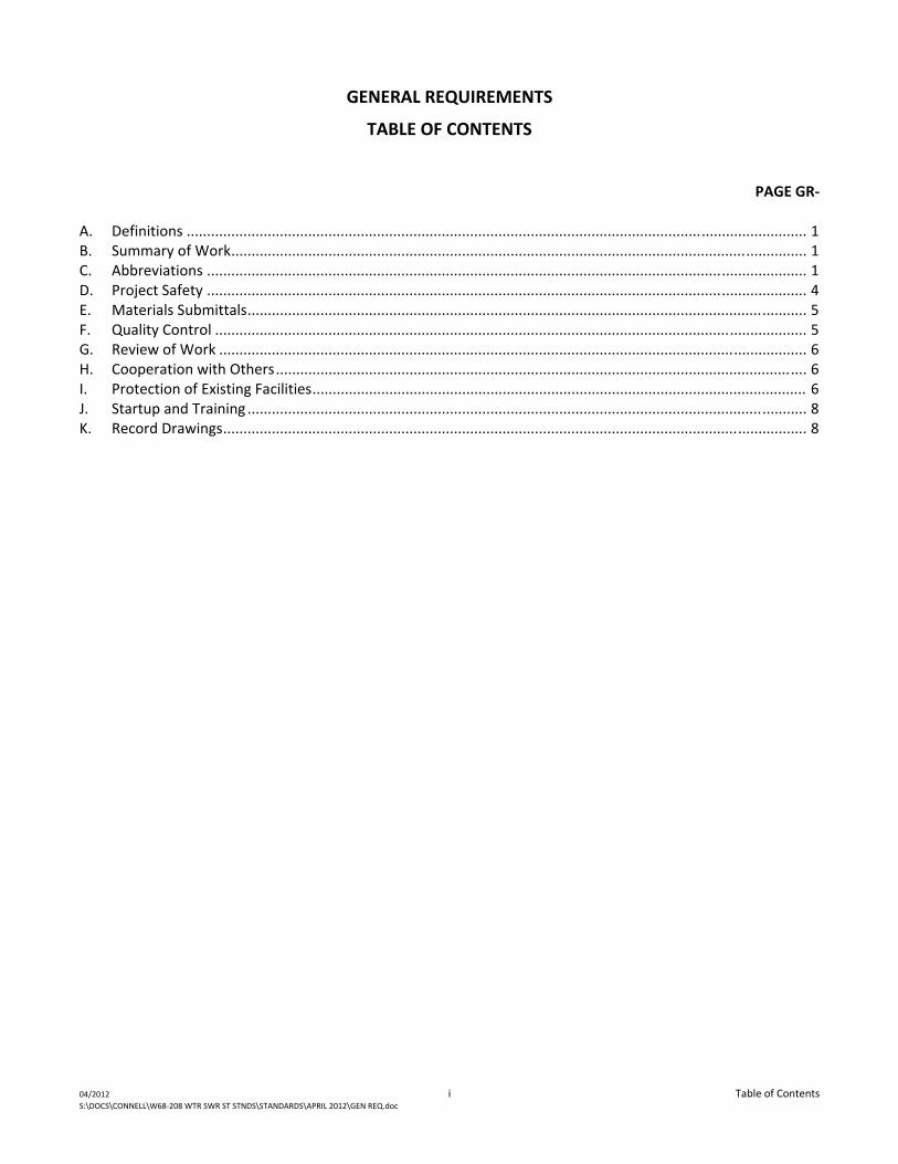
PAGE GR‐
A. Definitions ......................................................................................................................................................... 1 B. Summary of Work .............................................................................................................................................. 1 C. Abbreviations .................................................................................................................................................... 1 D. Project Safety .................................................................................................................................................... 4 E. Materials Submittals .......................................................................................................................................... 5 F. Quality Control .................................................................................................................................................. 5 G. Review of Work ................................................................................................................................................. 6 H. Cooperation with Others ................................................................................................................................... 6 I. Protection of Existing Facilities .......................................................................................................................... 6 J. Startup and Training .......................................................................................................................................... 8 K. Record Drawings ................................................................................................................................................ 8
GENERAL REQUIREMENTS
04/2012 GR‐1 General Requirements S:\DOCS\CONNELL\W68‐208 WTR SWR ST STNDS\STANDARDS\APRIL 2012\GEN REQ.doc
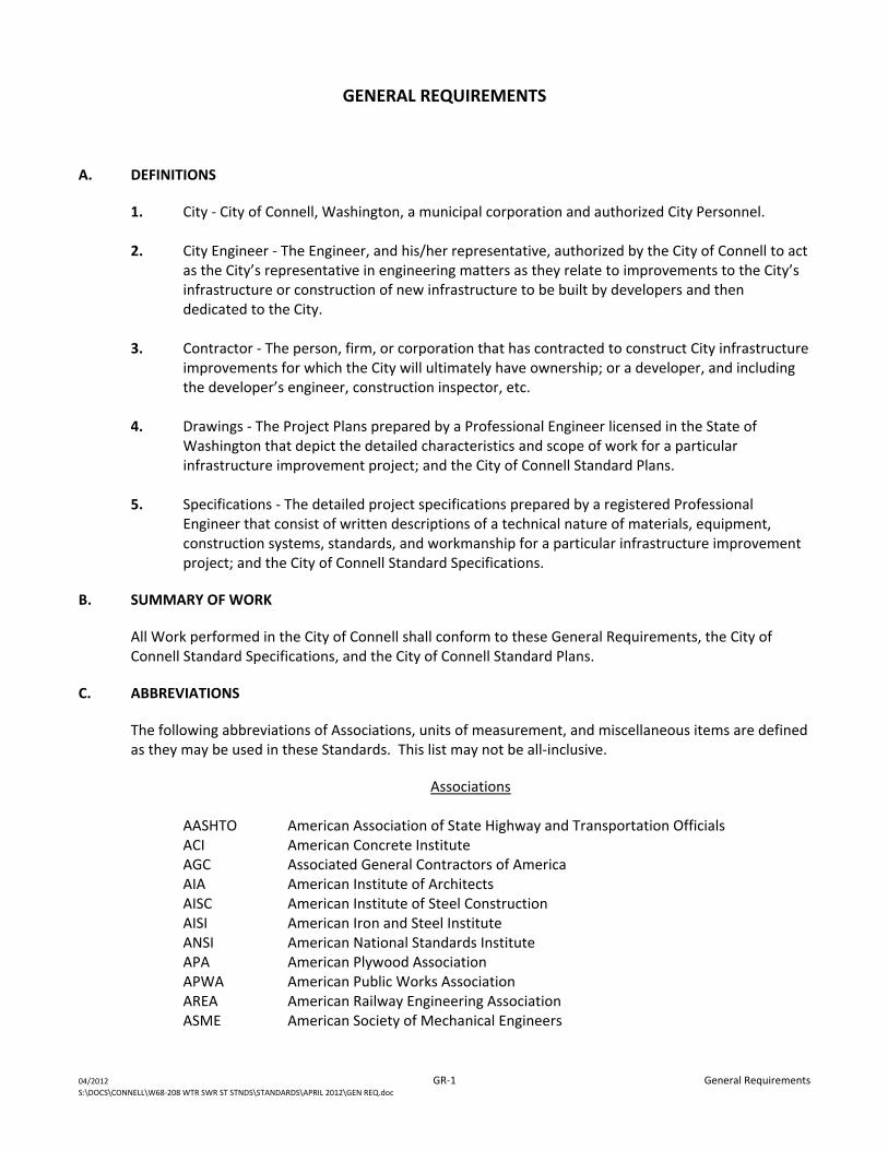
A. DEFINITIONS
1. City ‐ City of Connell, Washington, a municipal corporation and authorized City Personnel.
2. City Engineer ‐ The Engineer, and his/her representative, authorized by the City of Connell to act as the City’s representative in engineering matters as they relate to improvements to the City’s infrastructure or construction of new infrastructure to be built by developers and then dedicated to the City.
3. Contractor ‐ The person, firm, or corporation that has contracted to construct City infrastructure
improvements for which the City will ultimately have ownership; or a developer, and including the developer’s engineer, construction inspector, etc.
4. Drawings ‐ The Project Plans prepared by a Professional Engineer licensed in the State of
Washington that depict the detailed characteristics and scope of work for a particular infrastructure improvement project; and the City of Connell Standard Plans.
5. Specifications ‐ The detailed project specifications prepared by a registered Professional
Engineer that consist of written descriptions of a technical nature of materials, equipment, construction systems, standards, and workmanship for a particular infrastructure improvement project; and the City of Connell Standard Specifications.
B. SUMMARY OF WORK
All Work performed in the City of Connell shall conform to these General Requirements, the City of Connell Standard Specifications, and the City of Connell Standard Plans.
C. ABBREVIATIONS
The following abbreviations of Associations, units of measurement, and miscellaneous items are defined as they may be used in these Standards. This list may not be all‐inclusive.
Associations
AASHTO American Association of State Highway and Transportation Officials ACI American Concrete Institute AGC Associated General Contractors of America AIA American Institute of Architects AISC American Institute of Steel Construction AISI American Iron and Steel Institute ANSI American National Standards Institute APA American Plywood Association APWA American Public Works Association AREA American Railway Engineering Association ASME American Society of Mechanical Engineers
GENERAL REQUIREMENTS
04/2012 GR‐2 General Requirements S:\DOCS\CONNELL\W68‐208 WTR SWR ST STNDS\STANDARDS\APRIL 2012\GEN REQ.doc
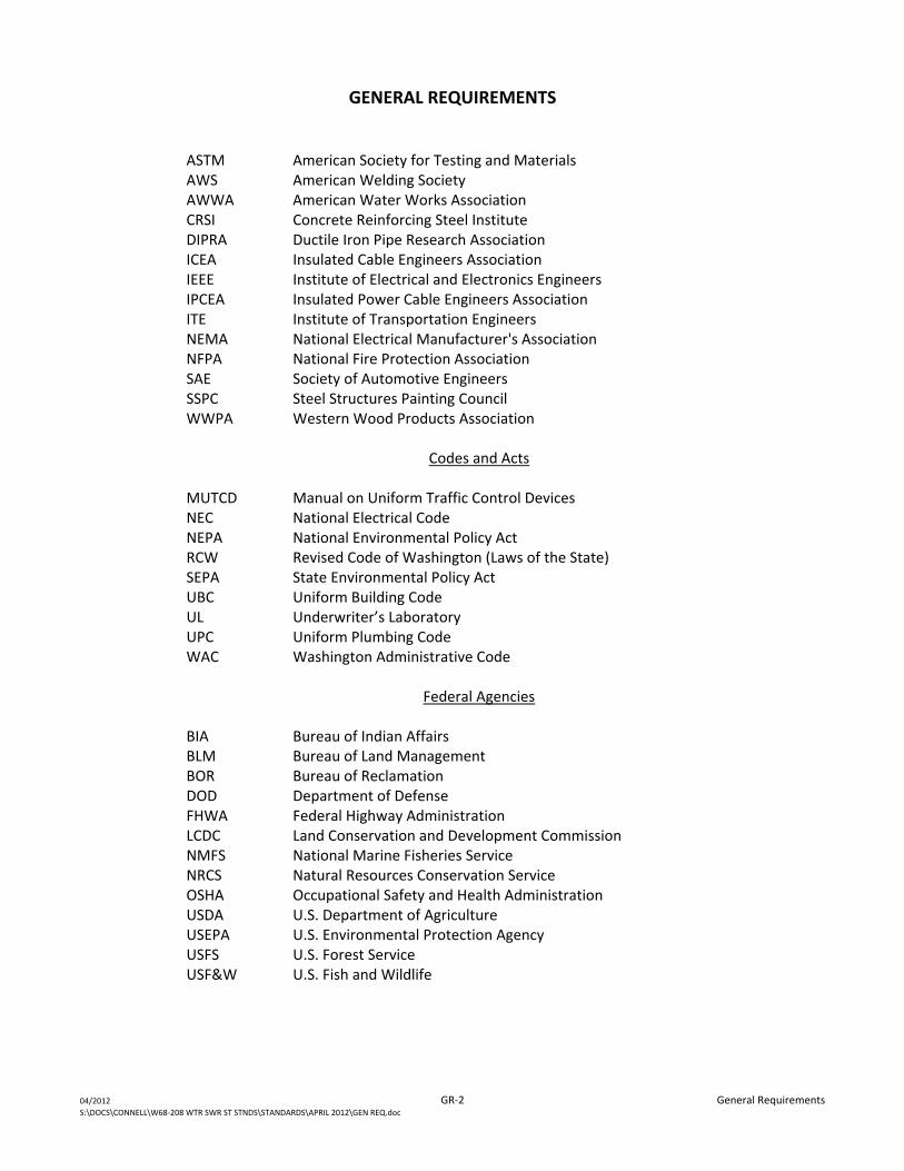
ASTM American Society for Testing and Materials AWS American Welding Society AWWA American Water Works Association CRSI Concrete Reinforcing Steel Institute DIPRA Ductile Iron Pipe Research Association ICEA Insulated Cable Engineers Association IEEE Institute of Electrical and Electronics Engineers IPCEA Insulated Power Cable Engineers Association ITE Institute of Transportation Engineers NEMA National Electrical Manufacturer's Association NFPA National Fire Protection Association SAE Society of Automotive Engineers SSPC Steel Structures Painting Council WWPA Western Wood Products Association
Codes and Acts
MUTCD Manual on Uniform Traffic Control Devices NEC National Electrical Code NEPA National Environmental Policy Act RCW Revised Code of Washington (Laws of the State) SEPA State Environmental Policy Act UBC Uniform Building Code UL Underwriter’s Laboratory UPC Uniform Plumbing Code WAC Washington Administrative Code
Federal Agencies
BIA Bureau of Indian Affairs BLM Bureau of Land Management BOR Bureau of Reclamation DOD Department of Defense FHWA Federal Highway Administration LCDC Land Conservation and Development Commission NMFS National Marine Fisheries Service NRCS Natural Resources Conservation Service OSHA Occupational Safety and Health Administration USDA U.S. Department of Agriculture USEPA U.S. Environmental Protection Agency USFS U.S. Forest Service USF&W U.S. Fish and Wildlife
GENERAL REQUIREMENTS
04/2012 GR‐3 General Requirements S:\DOCS\CONNELL\W68‐208 WTR SWR ST STNDS\STANDARDS\APRIL 2012\GEN REQ.doc
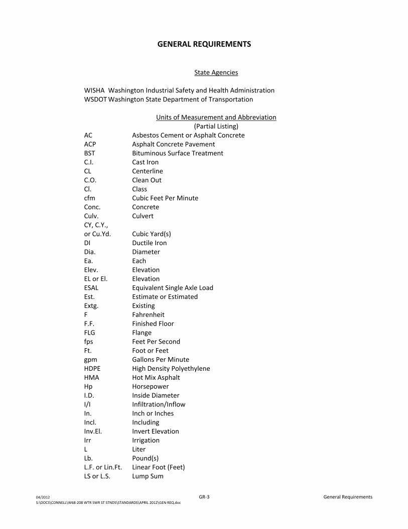
State Agencies
WISHA Washington Industrial Safety and Health Administration WSDOT Washington State Department of Transportation
Units of Measurement and Abbreviation
(Partial Listing) AC Asbestos Cement or Asphalt Concrete ACP Asphalt Concrete Pavement BST Bituminous Surface Treatment C.I. Cast Iron CL Centerline C.O. Clean Out Cl. Class cfm Cubic Feet Per Minute Conc. Concrete Culv. Culvert CY, C.Y., or Cu.Yd. Cubic Yard(s) DI Ductile Iron Dia. Diameter Ea. Each Elev. Elevation EL or El. Elevation ESAL Equivalent Single Axle Load Est. Estimate or Estimated Extg. Existing F Fahrenheit F.F. Finished Floor FLG Flange fps Feet Per Second Ft. Foot or Feet gpm Gallons Per Minute HDPE High Density Polyethylene HMA Hot Mix Asphalt Hp Horsepower I.D. Inside Diameter I/I Infiltration/Inflow In. Inch or Inches Incl. Including Inv.El. Invert Elevation Irr Irrigation L Liter Lb. Pound(s) L.F. or Lin.Ft. Linear Foot (Feet) LS or L.S. Lump Sum
GENERAL REQUIREMENTS
04/2012 GR‐4 General Requirements S:\DOCS\CONNELL\W68‐208 WTR SWR ST STNDS\STANDARDS\APRIL 2012\GEN REQ.doc
Max. Maximum MH Manhole MJ Mechanical Joint Min. Minimum MPH Miles Per Hour N.T.S. Not to Scale O.C. On Center O.D. Outside Diameter PL Plate PVC Polyvinyl Chloride psi Pounds Per Square Inch Q Flow Rate R Radius REQD. Required RPM Revolutions Per Minute R/W Right‐of‐Way S Sanitary Sewer SCH Schedule SD Storm Drain Sht. Sheet Stl. Steel SWL Static Water Level SY, S.Y., or Sq.Yd. Square Yard TDH Total Dynamic Head TM Test Method Typ. Typical W Water WS Wood Stave
D. PROJECT SAFETY
The Contractor shall be solely responsible for initiating, maintaining, and supervising all safety precautions and programs in connection with the Work, including excavation safety. The Contractor shall comply with all applicable laws, ordinances, rules, regulations, and orders of any public body having jurisdiction as it relates to project and work safety.
The Contractor shall maintain local access to area residents and emergency traffic throughout the life of the project and coordinate construction activities closely with area residents to keep them informed of operations that may impact their use of any streets or roadways.
All signs, barricades, barriers, lights, cones, trench boxes, shoring/bracing, and other such "devices" required to warn, protect, or direct the public and workmen during the lift of the Contract shall be furnished, installed, moved, and removed by the Contractor. When conditions warrant their use, flagpersons shall also be provided by the Contractor.
GENERAL REQUIREMENTS
04/2012 GR‐5 General Requirements S:\DOCS\CONNELL\W68‐208 WTR SWR ST STNDS\STANDARDS\APRIL 2012\GEN REQ.doc
The City is not responsible for determining whether proper safety precautions, etc., are being utilized. Should the Contractor fail to furnish the necessary protective measures, the City may, but shall not be required to, bring to the Contractor's attention by written notice of such failure and the Contractor shall undertake such corrective measures as is proper.
All construction work shall be performed in accordance with the provisions of the Industrial Safety Health Administrative Safety Standards of the State of Washington Department of Labor and Industry, and other applicable regulations. It shall be the Contractor's responsibility to meet all requirements of Chapter 296 of the State of Washington Administrative Rules.
The materials used for and the installation of all warning and traffic control devices shall conform to the Standard Specifications for Road, Bridge, and Municipal Construction ‐ current edition, Washington State Department of Transportation, and the Manual of Uniform Traffic Control Devices for Streets and Highways, U.S. Department of Transportation, Federal Highway Administration, current edition.
It shall be the Contractor's sole responsibility to provide a "competent person" as defined in the regulations to be on the project site during all trenching operations. The "competent person" appointed by the Contractor shall fulfill all requirements of the regulations.
Prior to opening an excavation, the Contractor shall arrange for field location of utility installations such as sewer, telephone, fuel, electric, gas, water lines, or any other underground installations that reasonably may be expected to be encountered during the excavation work. When excavation operations approach the estimated location of underground installations, the Contractor shall determine the exact location of the installations by safe and acceptable means. While the excavation is open, underground installations shall be protected, supported, or removed as necessary to safeguard workers.
It shall be the Contractor's responsibility to provide all physical barrier protection at all excavations. All wells, pits, shafts, etc., shall be barricaded or covered. Further, no trenches shall be left open at any time unless guarded with adequate barricades, warning lamps, and signs. Proper traffic and pedestrian control shall be provided by the Contractor.
E. MATERIALS SUBMITTALS
The Contractor shall submit Shop Drawings, samples of materials, and/or manufacturer's data sheets as deemed necessary by the City.
All submittals or resubmittals shall be accompanied by and furnished in accordance with the Transmittal of Shop Drawings, Equipment Data, Material Samples, or Manufacturer’s Certificates of Compliance form provided at the end of these General Requirements. All submittals shall be submitted at a time sufficiently early to allow review of same by the City.
F. QUALITY CONTROL
The Contractor shall be responsible for providing his/her own construction testing, monitoring, and quality control program to ensure the materials used on the project and in the Contractor’s operations are in compliance with these Standard Specifications and City of Connell Standard Plans. The Contractor
GENERAL REQUIREMENTS
04/2012 GR‐6 General Requirements S:\DOCS\CONNELL\W68‐208 WTR SWR ST STNDS\STANDARDS\APRIL 2012\GEN REQ.doc
will perform tests and use test methods as required in the Standard Specifications for Road, Bridge, and Municipal Construction ‐ current edition, Washington State Department of Transportation. A written quality control program shall be provided to the City for review prior to any work being performed. The plan shall describe how the Contractor will monitor and ensure quality control throughout the work. Materials, equipment, or work that fails to meet these Standard Specifications and City of Connell Standard Plans shall not be used in the Work.
The City or representative will at all times have access to the Work. In addition, authorized representatives and agents of any participating federal or state agency shall be permitted to review all Work, materials, invoices of materials, and other relevant data and records. The Contractor will provide proper facilities for such access and observation of the Work and also for any review or testing thereof. The Contractor shall notify testing personnel, including testing personnel provided by the City, at least 24 hours in advance of operations to allow for personnel assignments and test scheduling. All materials to be tested shall be provided by the Contractor at his/her expense. After tests are completed, the Contractor shall be responsible for repairing test areas to match original conditions. The Contractor shall pay for all additional reviews and retesting required because of defective work or ill‐timed notices.
Tests or reviews by the City or others shall not relieve the Contractor from his/her obligations to perform the Work in accordance with the requirements of these Standard Specifications and City of Connell Standard Plans and does not make the City, or others, an insurer of the Contractor’s Work.
G. REVIEW OF WORK
It is not the intent of the City to provide continuous or full‐time observation of all Work. When required by the City, the Contractor shall fax the City a daily report of his Work progress and proposed Work schedule for the next two days.
H. COOPERATION WITH OTHERS
The Contractor shall cooperate with the residents and business owners in the area to provide good access to private property whenever possible. Sidewalks shall be kept clear at all times of any construction materials. Barricades, traffic cones, blinkers, and signing shall be used to direct the public through the Work area safely.
I. PROTECTION OF EXISTING FACILITIES
1. The Contractor shall be responsible for the protection and perpetuation of existing land survey, property, or construction monuments. The Contractor shall give the City a minimum of 48 hours notice prior to working in the vicinity of any such monument that he/she may disturb so the City can arrange for such monuments to be referenced. When proper notice is provided, the City shall have any disturbed monuments restored following construction. Should the Contractor fail to provide adequate notice to the City, he/she shall be responsible for the expense of having the disturbed monument restored by a qualified surveyor.
The Contractor shall carefully preserve benchmarks, reference points, and stakes set by others. In the case of willful or careless destruction by the Contractor, he/she shall be charged with the
GENERAL REQUIREMENTS
04/2012 GR‐7 General Requirements S:\DOCS\CONNELL\W68‐208 WTR SWR ST STNDS\STANDARDS\APRIL 2012\GEN REQ.doc
resulting expense of replacement and shall be responsible for any mistakes or liability that may be caused by the loss or disturbance.
2. The Contractor shall be responsible for the actual locating and protecting of existing utilities. The Contractor, prior to commencement of work, shall contact existing Utility Companies such as water, sewer, power, telephone, gas, etc., to have the Utility Companies locate all utilities which will be affected by the work to be performed. The Contractor shall give 48‐hour notification in accordance with RCW 19.122. The "call before you dig" number is 1‐800‐553‐4344 or 811. The Contractor shall perform all necessary coordination work with the Utility Companies in performing the work and shall be fully responsible for any damage to existing utilities caused by the Contractor's operations. The Contractor shall make any advance exploration necessary to protect all existing utilities and to properly plan the installation of pipelines or other work to the design line and grade.
The owner of the utilities shall normally be responsible for taking the utility out of service if necessary for the performance of the work; i.e., shutting valves, etc. In the case of water valves, the owner of the water system may operate the valves or request the Contractor to do so. When the Contractor is requested to do so, the Contractor shall operate water valves as a normal part of the work at no additional cost to the City. All water valves shall be operated as instructed by the owner of the valves. It can be expected that some valves may not fully operate properly which may require that additional valves be operated. This situation shall be considered a normal requirement of the work.
3. The Contractor shall receive prior approval from the appropriate authority or utility owner before any public or private utility service is interrupted. The Contractor shall give a minimum of 4 hours notice to all utility customers who will be affected by the Contractor's operations. No utility service shall be disconnected or interrupted for more than 9 hours or as required by the utility owner, whichever is less, in any 24‐hour period. When disruption of service will be longer than 9 hours in any one day, the Contractor shall provide safe and appropriate temporary service. All temporary service shall be coordinated with the utility owner. When regular utility service interruption is required during the course of the work, the Contractor shall submit a written plan to the City and utility owner which details proposed work plan notification procedures, and estimated extent of service interruption. The Contractor must obtain written approval of his plan from the utility owner prior to interrupting the utility service. As a minimum, notification shall include door hangers and public notification in the newspaper and radio, as appropriate. Personal contact shall be made where practical. The Contractor shall make every effort possible to provide continuous utility service to all utility customers.
4. The Contractor shall arrange his/her work schedule such that all phases of Work, once started,
shall be diligently pursued until completed. The intent is that the work area shall not be disturbed for undue periods of time. Work shall not be left uncompleted. If the City determines that Work is not being diligently completed, he/she shall request the Contractor to complete said Work.
Cleaning up shall be a continuing process from the start of the Work to final acceptance of the project. The Contractor shall, at all times, at his/her own expense and without further order,
GENERAL REQUIREMENTS
04/2012 GR‐8 General Requirements S:\DOCS\CONNELL\W68‐208 WTR SWR ST STNDS\STANDARDS\APRIL 2012\GEN REQ.doc
keep property on which Work is in progress free from accumulations of waste material or rubbish caused by employees or by the Work, and at all times during the construction period shall maintain structure sites, rights‐of‐way, easements, adjacent property, and the surfaces of streets and roads on which Work is being done in a safe condition for the Contractor's workers and the public. Accumulations of waste materials that might constitute a fire hazard will not be permitted. Spillage from the Contractor's hauling vehicles on traveled public or private roads shall be promptly cleaned up. The Contractor shall take appropriate action to control dust caused by his/her operations. This shall include, but not be limited to, watering of exposed areas, cleaning of roadways, etc. This is considered a normal part of the construction project. Upon completion of the Work, the Contractor shall, at his/her own expense, remove all temporary structures, rubbish, waste material, equipment, and supplies resulting from his/her operations. He/she shall leave such lands in a neat and orderly condition that is at least as good as the condition in which he/she found them prior to his/her operations. Should the Contractor fail to provide said cleanup upon 24‐hour written notice, the City shall have the right to perform such Work at the expense of the Contractor and withhold the cost from the Contractor's payments.
The Contractor shall replace or restore, equivalent to their original condition, all surfaces or existing facilities disturbed by his work, whether within or outside of the work areas. Restoration work will include, but is not limited to, roadways, utilities, structures, landscaping, etc.
J. STARTUP AND TRAINING
It shall be the Contractor's responsibility to install all system components in accordance with the Manufacturer's recommendations.
As part of this Work, the Contractor shall provide startup training to the City in sufficient detail so the City is fully familiar with the proper operation and maintenance of project components and systems. The startup training shall occur after the construction work is complete and properly functioning. This work may also include development of an Operation and Maintenance Manual.
K. RECORD DRAWINGS
The Contractor shall maintain on the job site an up‐to‐date, complete, and accurate set of record drawings. These drawings shall include all Work performed by the Contractor and shall note any changes or deviations made from the details shown on the construction drawings. Such deviations would include, but not be limited to, dimensional changes, location, grade changes, elevation changes, material type, configuration, etc. All changes shall be neatly and accurately shown on the record drawings. The record drawings shall also include all required job photos.
The Contractor shall provide at least two swing tie references to all buried service line taps, valves, manholes, etc., from an above‐ground reference point. Swing tie measurements shall be from some permanent reference point, i.e., house corner, fire hydrant, power pole, etc. All ties shall be provided in such a way that the buried utility can be accurately located after construction work is complete. All buried improvements shall be described in detail including location, type, size, depth, brand name,
GENERAL REQUIREMENTS
04/2012 GR‐9 General Requirements S:\DOCS\CONNELL\W68‐208 WTR SWR ST STNDS\STANDARDS\APRIL 2012\GEN REQ.doc
model numbers, etc. Buried improvements shall include valves, fittings, repair clamps, connections to existing lines, etc. All offsets shall be appropriately noted on the drawings.
The Contractor shall also note the locations, types, size, depth, etc., of any existing utilities encountered during the performance of the Work. The record drawings shall be available for inspection during the project by the City. The Contractor shall keep the record drawings current each day to avoid loss of critical or important information.
Upon completion, two paper copies on 11" x 17" paper and one electronic copy in PDF format shall be submitted to the City. Incomplete or inaccurate drawings will be returned for revision and resubmittal. Final acceptance will not be granted without acceptable record drawings.
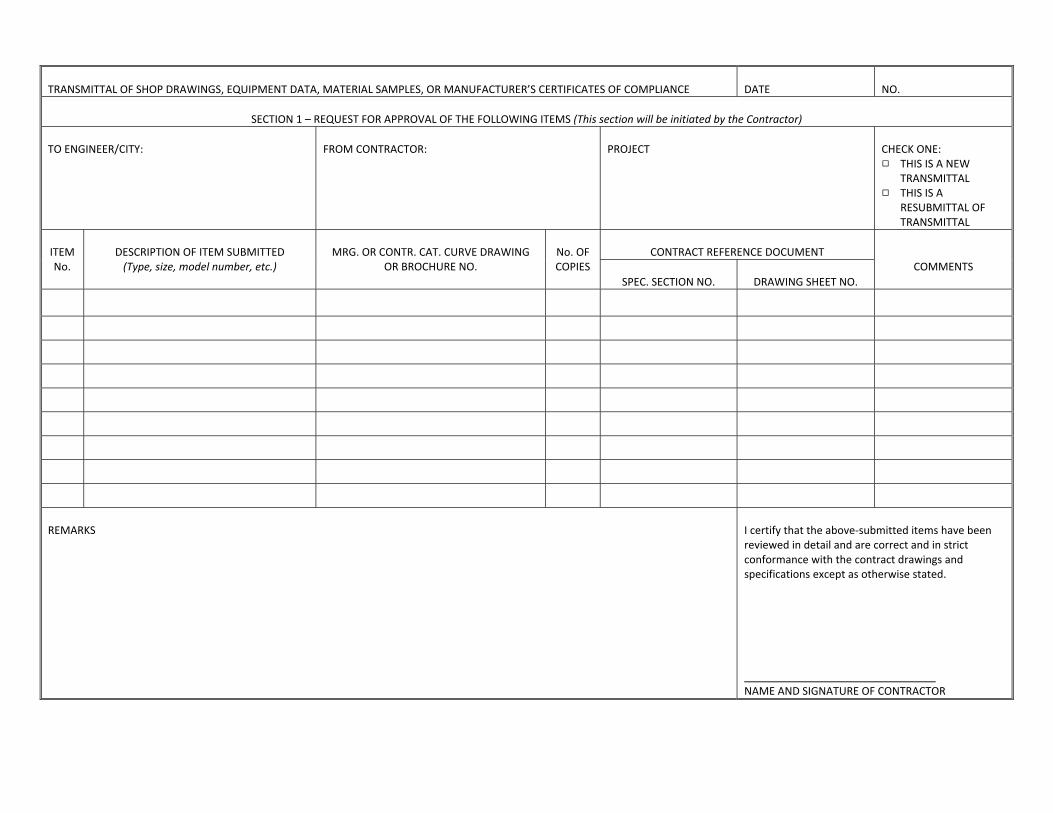
TRANSMITTAL OF SHOP DRAWINGS, EQUIPMENT DATA, MATERIAL SAMPLES, OR MANUFACTURER’S CERTIFICATES OF COMPLIANCE
DATE
NO.
SECTION 1 – REQUEST FOR APPROVAL OF THE FOLLOWING ITEMS (This section will be initiated by the Contractor)
TO ENGINEER/CITY:
FROM CONTRACTOR:
PROJECT
CHECK ONE: 9 THIS IS A NEW TRANSMITTAL 9 THIS IS A RESUBMITTAL OF TRANSMITTAL
ITEM No.
DESCRIPTION OF ITEM SUBMITTED (Type, size, model number, etc.)
MRG. OR CONTR. CAT. CURVE DRAWING
OR BROCHURE NO.
No. OF COPIES
CONTRACT REFERENCE DOCUMENT
COMMENTS SPEC. SECTION NO.
DRAWING SHEET NO.
REMARKS
I certify that the above‐submitted items have been reviewed in detail and are correct and in strict conformance with the contract drawings and specifications except as otherwise stated. NAME AND SIGNATURE OF CONTRACTOR
STANDARD SPECIFICATIONS
SECTION 1 EXCAVATION AND BACKFILL OF TRENCHES
TABLE OF CONTENTS
SECTION 1
EXCAVATION AND BACKFILL OF TRENCHES
04/2012 i Table of Contents S:\DOCS\CONNELL\W68‐208 WTR SWR ST STNDS\STANDARDS\APRIL 2012\EXCAVATION & BACKFILL OF TRENCHES.docx Anderson Perry & Associates, Inc.
PART 1 ‐ General ..................................................................................................................................................... 1‐1 1.1 Summary ................................................................................................................................................. 1‐1
PART 2 ‐ Materials .................................................................................................................................................. 1‐1 2.1 Bedding and Select Backfill ..................................................................................................................... 1‐1 2.2 General Backfill ....................................................................................................................................... 1‐1
PART 3 ‐ Execution .................................................................................................................................................. 1‐1 3.1 Clearing and Grubbing ............................................................................................................................ 1‐1 3.2 Cutting of Asphalt Pavement and Concrete Sidewalks, Curbs and Driveways ....................................... 1‐2 3.3 Trench Excavation................................................................................................................................... 1‐2 3.4 Shoring, Sheeting, and Bracing of Trenches ........................................................................................... 1‐3 3.5 Dewatering Excavated Areas .................................................................................................................. 1‐3 3.6 Location of Excavated Materials ............................................................................................................ 1‐3 3.7 Disposal of Excavated Materials ............................................................................................................. 1‐3 3.8 Trench Backfill ........................................................................................................................................ 1‐4 3.9 Execution of Dust and Mud Control ....................................................................................................... 1‐4 3.10 Restoration, Finishing, and Cleanup ....................................................................................................... 1‐4
STANDARD SPECIFICATIONS
SECTION 1
EXCAVATION AND BACKFILL OF TRENCHES
04/2012 1‐1 Excavation and Backfill of Trenches S:\DOCS\CONNELL\W68‐208 WTR SWR ST STNDS\STANDARDS\APRIL 2012\EXCAVATION & BACKFILL OF TRENCHES.docx Anderson Perry & Associates, Inc.
PART 1 ‐ GENERAL
1.1 Summary
These specifications cover the excavation and backfill of trenches for the installation of storm sewer, sanitary sewer, water lines, service lines, pressure sewer lines, and other underground utilities. This work must also conform to the City of Connell Standard Plans and the General Requirements.
PART 2 ‐ MATERIALS
2.1 Bedding and Select Backfill
Bedding and select backfill shall be crushed surfacing top course per WSDOT Standard Specification 9‐03.9(3) or native sand when approved by the City and shall conform to the Standard Specifications for Road, Bridge, and Municipal Construction ‐ current edition, Washington State Department of Transportation.
2.2 General Backfill
A. General backfill will consist of material excavated from the trench, or material imported by the Contractor. General backfill material shall be free of vegetative matter, boulders (10‐inch plus), frozen material and any other unsuitable material, and shall have a moisture content that will allow for the required compaction of the general backfill material unless approved otherwise by the City. Use of backfill material containing consolidated masses 10‐inch in diameter or greater is prohibited.
B. When necessary, the Contractor shall selectively separate suitable general backfill material from unsuitable general backfill material.
PART 3 ‐ EXECUTION
3.1 Clearing and Grubbing
A. Contractor shall do all clearing and grubbing and removal of structures, etc. necessary to permit proper installation of the pipeline and to eliminate the possibility of stumps, logs, brush, or rubbish being mixed with the backfill material. A sufficient amount of all stumps and stump roots shall be removed so that any future removal of any remaining parts of the stumps and/or roots will not damage the pipeline. All stumps, roots, logs, brush, and rubbish shall be removed and disposed of in conformance with the requirements of local authorities controlling air pollution, and solid waste disposal.
B. Should the area in which construction takes place be served by rural mail carrier service, the Contractor shall cooperate with the mail service and re‐install, in a convenient location, any rural mail boxes which will have to be removed or be blocked by construction operations. As soon as the work is completed, all mail boxes removed shall be replaced undamaged in their original location.
STANDARD SPECIFICATIONS
SECTION 1
EXCAVATION AND BACKFILL OF TRENCHES
04/2012 1‐2 Excavation and Backfill of Trenches S:\DOCS\CONNELL\W68‐208 WTR SWR ST STNDS\STANDARDS\APRIL 2012\EXCAVATION & BACKFILL OF TRENCHES.docx Anderson Perry & Associates, Inc.
C. As soon as the work is completed, all signs, guardrails, utility poles, fences, etc., which were moved for the construction operation shall be replaced undamaged in their original location. Damaged items shall be replaced by the Contractor with new items of equal quality.
3.2 Cutting of Asphalt Pavement and Concrete Sidewalks, Curbs and Driveways
A. Where the excavation is made in a paved street, the asphalt surface shall be cut on each side of the trench prior to excavation, to provide a vertical joint in the surface. Cutting of the asphalt will be made with a saw designed for the cutting of asphalt.
B. Prior to excavating across a concrete structure such as a curb, sidewalk, or driveway, the Contractor shall saw cut and remove a section of the structure in order to provide for his excavation. The dimensions of the removed section shall be such that the Contractor's excavation will not result in undermining of the remaining structure.
C. The Contractor shall cut the concrete structure with a diamond saw or other equipment designed for that purpose such that a neat, straight, vertical edge is left on the remaining concrete structure. The Contractor shall similarly cut and remove any such concrete structure undermined or damaged by his construction work.
D. Following proper backfill and compaction of his excavation, as specified herein, the Contractor shall repair streets, replace the curbs, sidewalks, or driveways in conformance with surface restoration, equal to the condition prior to removal.
3.3 Trench Excavation
A. When solid rock is encountered in trench excavation, the City shall be notified immediately.
B. Trench Width
1. The maximum trench width in the pipe zone shall be 2 feet plus the O.D. of the pipe and the minimum trench width in the pipe zone shall be 1 foot plus the O.D. of the pipe. This width shall be maintained to the top of the pipe.
2. The maximum clear width above the top of the pipe will not be limited except in cases where excess width of excavation would cause damage to adjacent structures or utilities.
C. Exploratory Work
Contractor shall perform appropriate exploratory work to locate utilities when they are known to exist but the specific location is unknown or not marked accurately. Appropriate exploratory work shall be performed in these situations.
STANDARD SPECIFICATIONS
SECTION 1
EXCAVATION AND BACKFILL OF TRENCHES
04/2012 1‐3 Excavation and Backfill of Trenches S:\DOCS\CONNELL\W68‐208 WTR SWR ST STNDS\STANDARDS\APRIL 2012\EXCAVATION & BACKFILL OF TRENCHES.docx Anderson Perry & Associates, Inc.
3.4 Shoring, Sheeting, and Bracing of Trenches
A. The Contractor shall adequately sheet and brace the trench during excavation whenever necessary to satisfy trench safety standards, prevent cave‐ins, or to protect adjacent structures or property. Where sheeting and bracing are used, the Contractor shall increase trench widths for the bracing material accordingly.
B. The sheeting must be kept in place until the pipe has been placed, backfilled at the pipe zone, tested for defects, and repaired if necessary. All sheeting, shoring, and bracing of trenches shall conform to the requirements of the public agency having jurisdiction.
3.5 Dewatering Excavated Areas
A. All groundwater, seepage, or stormwater that may occur or accumulate in the excavation during the progress of the work shall be removed. In areas where the nature of soil and hydrostatic pressures are of such a character as to develop a quick condition in the earth mass of the trench, the dewatering operation shall be conducted so that the hydrostatic pressure will be reduced to or near zero in the immediate vicinity of the trench.
B. All excavations shall be kept free of water during the construction or until otherwise requested by the City.
C. The Contractor shall dispose of all waste and water removed from the trench. Disposal shall be in accordance with all state and local regulations.
3.6 Location of Excavated Materials
A. During trench excavation, the excavated material shall be located within the construction easement or right‐of‐way so that the excavated material will not obstruct any private or public traveled roadways or streets, or cause undue damage to the streets.
B. Contractor shall provide means of containing overly saturated soils, i.e., muck, or remove the muck from the work area as it is excavated, if such soils are encountered in the excavation. The intent is to prevent excessive damage or disruption to street rights‐of‐way or easement beyond what would normally occur during such work. Pile and maintain material from trenches so that the toe of the slope of the material excavated is at least two feet from the edge of the trench. It shall be the Contractor's responsibility, however, to determine the safe loading of all trenches.
3.7 Disposal of Excavated Materials
Contractor shall dispose of all excavated material, which is not required for, or is unsuitable for, backfill. The Contractor's method of disposal shall comply with regulations of the governing body having jurisdiction.
STANDARD SPECIFICATIONS
SECTION 1
EXCAVATION AND BACKFILL OF TRENCHES
04/2012 1‐4 Excavation and Backfill of Trenches S:\DOCS\CONNELL\W68‐208 WTR SWR ST STNDS\STANDARDS\APRIL 2012\EXCAVATION & BACKFILL OF TRENCHES.docx Anderson Perry & Associates, Inc.
3.8 Trench Backfill
A. All backfill material shall be placed into the trench so that free fall of the materials into the trench is prevented until at least two feet of cover is provided over the pipe. Under no circumstances shall sharp or heavy pieces of material be allowed to drop directly onto the pipe. Methods of backfilling, other than as specified herein, shall be used only upon the approval of the City.
B. Bedding and Select Backfill
1. A minimum 4‐inch depth of bedding shall be placed on the trench bottom, compacted to 85 percent of the maximum density as determined by ASTM D698 or WSDOT Test Method 606, as applicable, and smoothed to provide uniform bedding so the pipe is supported along its full length and not by the bells. Bell holes at each joint shall be provided to ensure support along the entire pipe length.
2. It shall be understood that the 4‐inch depth is a minimum depth only, not an average depth and does not preclude the Contractor at his option from placing additional depth of bedding to facilitate his work. Once the pipe is properly installed, the bedding material shall be brought up to the spring line of the pipe in 4‐inch lifts and compacted to 85 percent density. Care shall be used to ensure that the bedding material is properly worked under the haunch of the pipe for its full length.
3. Select backfill shall then be brought up in 4‐inch lifts to a minimum 6 inches above the top of the pipe, leveled and compacted to 85 percent of ASTM D698 or WSDOT Test Method 606, as applicable, density. Compaction of the bedding and select backfill by hand tamping will be allowed if the 85 percent density is achieved; otherwise, mechanical tamping will be required.
C. General backfill shall be placed in horizontal lifts not to exceed 12 inches in depth and compacted to 90 percent of the laboratory density as determined by ASTM D1557 or WSDOT Test Method 606, as applicable. The method of compaction shall be selected by the Contractor.
3.9 Execution of Dust and Mud Control
If the Contractor fails to properly control the dust and mud, the City may request him to do so in writing. If, after 24 hours from this request, the Contractor has not corrected the dust or mud problem, the City may elect to have the corrective work performed and charge the Contractor for the cost of this work.
3.10 Restoration, Finishing, and Cleanup
A. The Contractor shall restore or replace all paved surfaces, graveled surfaces, curbing, sidewalks, trees and shrubbery, lawns, pastures and fences, or other existing facilities disturbed by his work unless otherwise specified. Restoration and cleanup shall be a continuing operation and shall be diligently pursued until completed.
STANDARD SPECIFICATIONS
SECTION 1
EXCAVATION AND BACKFILL OF TRENCHES
04/2012 1‐5 Excavation and Backfill of Trenches S:\DOCS\CONNELL\W68‐208 WTR SWR ST STNDS\STANDARDS\APRIL 2012\EXCAVATION & BACKFILL OF TRENCHES.docx Anderson Perry & Associates, Inc.
B. All surplus material and temporary structures as well as excess excavation shall be removed by the Contractor and the entire site of Contractor operations shall be left in a neat and clean condition.
C. Surface restoration shall be performed in accordance with Standard Specification 6, Surface Restoration. All other existing facilities shall be replaced or restored equal to their original condition.
SECTION 2 WATER LINES
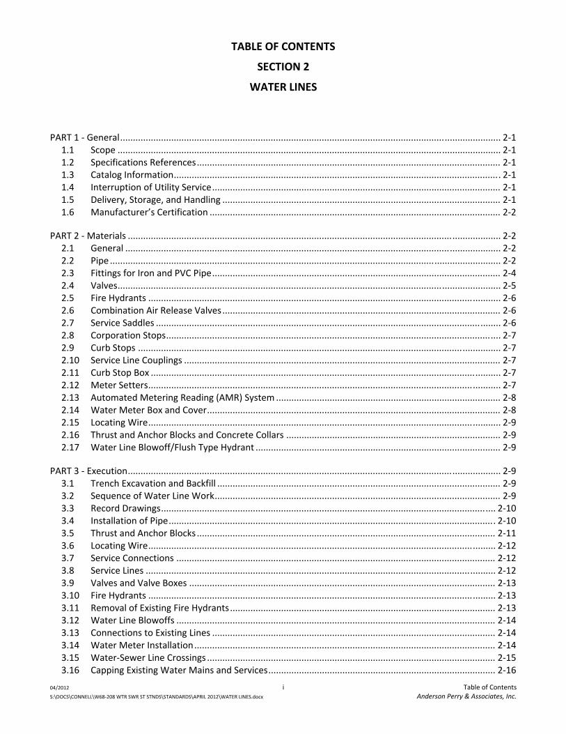
TABLE OF CONTENTS
SECTION 2
WATER LINES
04/2012 i Table of Contents S:\DOCS\CONNELL\W68‐208 WTR SWR ST STNDS\STANDARDS\APRIL 2012\WATER LINES.docx Anderson Perry & Associates, Inc.
PART 1 ‐ General ..................................................................................................................................................... 2‐1 1.1 Scope ...................................................................................................................................................... 2‐1 1.2 Specifications References ....................................................................................................................... 2‐1 1.3 Catalog Information ................................................................................................................................ 2‐1 1.4 Interruption of Utility Service ................................................................................................................. 2‐1 1.5 Delivery, Storage, and Handling ............................................................................................................. 2‐1 1.6 Manufacturer’s Certification .................................................................................................................. 2‐2
PART 2 ‐ Materials .................................................................................................................................................. 2‐2 2.1 General ................................................................................................................................................... 2‐2 2.2 Pipe ......................................................................................................................................................... 2‐2 2.3 Fittings for Iron and PVC Pipe ................................................................................................................. 2‐4 2.4 Valves ...................................................................................................................................................... 2‐5 2.5 Fire Hydrants .......................................................................................................................................... 2‐6 2.6 Combination Air Release Valves ............................................................................................................. 2‐6 2.7 Service Saddles ....................................................................................................................................... 2‐6 2.8 Corporation Stops ................................................................................................................................... 2‐7 2.9 Curb Stops .............................................................................................................................................. 2‐7 2.10 Service Line Couplings ............................................................................................................................ 2‐7 2.11 Curb Stop Box ......................................................................................................................................... 2‐7 2.12 Meter Setters .......................................................................................................................................... 2‐7 2.13 Automated Metering Reading (AMR) System ........................................................................................ 2‐8 2.14 Water Meter Box and Cover ................................................................................................................... 2‐8 2.15 Locating Wire .......................................................................................................................................... 2‐9 2.16 Thrust and Anchor Blocks and Concrete Collars .................................................................................... 2‐9 2.17 Water Line Blowoff/Flush Type Hydrant ................................................................................................ 2‐9
PART 3 ‐ Execution .................................................................................................................................................. 2‐9 3.1 Trench Excavation and Backfill ............................................................................................................... 2‐9 3.2 Sequence of Water Line Work ................................................................................................................ 2‐9 3.3 Record Drawings ................................................................................................................................... 2‐10 3.4 Installation of Pipe ................................................................................................................................ 2‐10 3.5 Thrust and Anchor Blocks ..................................................................................................................... 2‐11 3.6 Locating Wire ........................................................................................................................................ 2‐12 3.7 Service Connections ............................................................................................................................. 2‐12 3.8 Service Lines ......................................................................................................................................... 2‐12 3.9 Valves and Valve Boxes ........................................................................................................................ 2‐13 3.10 Fire Hydrants ........................................................................................................................................ 2‐13 3.11 Removal of Existing Fire Hydrants ........................................................................................................ 2‐13 3.12 Water Line Blowoffs ............................................................................................................................. 2‐14 3.13 Connections to Existing Lines ............................................................................................................... 2‐14 3.14 Water Meter Installation ...................................................................................................................... 2‐14 3.15 Water‐Sewer Line Crossings ................................................................................................................. 2‐15 3.16 Capping Existing Water Mains and Services ......................................................................................... 2‐16
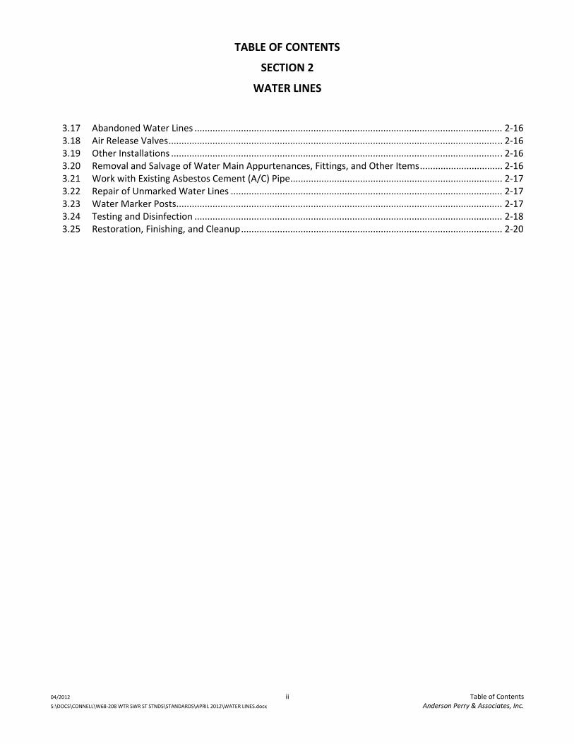
TABLE OF CONTENTS
SECTION 2
WATER LINES
04/2012 ii Table of Contents S:\DOCS\CONNELL\W68‐208 WTR SWR ST STNDS\STANDARDS\APRIL 2012\WATER LINES.docx Anderson Perry & Associates, Inc.
3.17 Abandoned Water Lines ....................................................................................................................... 2‐16 3.18 Air Release Valves ................................................................................................................................. 2‐16 3.19 Other Installations ................................................................................................................................ 2‐16 3.20 Removal and Salvage of Water Main Appurtenances, Fittings, and Other Items ................................ 2‐16 3.21 Work with Existing Asbestos Cement (A/C) Pipe .................................................................................. 2‐17 3.22 Repair of Unmarked Water Lines ......................................................................................................... 2‐17 3.23 Water Marker Posts .............................................................................................................................. 2‐17 3.24 Testing and Disinfection ....................................................................................................................... 2‐18 3.25 Restoration, Finishing, and Cleanup ..................................................................................................... 2‐20
STANDARD SPECIFICATIONS
SECTION 2
WATER LINES
04/2012 2‐1 Water Lines S:\DOCS\CONNELL\W68‐208 WTR SWR ST STNDS\STANDARDS\APRIL 2012\WATER LINES.docx Anderson Perry & Associates, Inc.
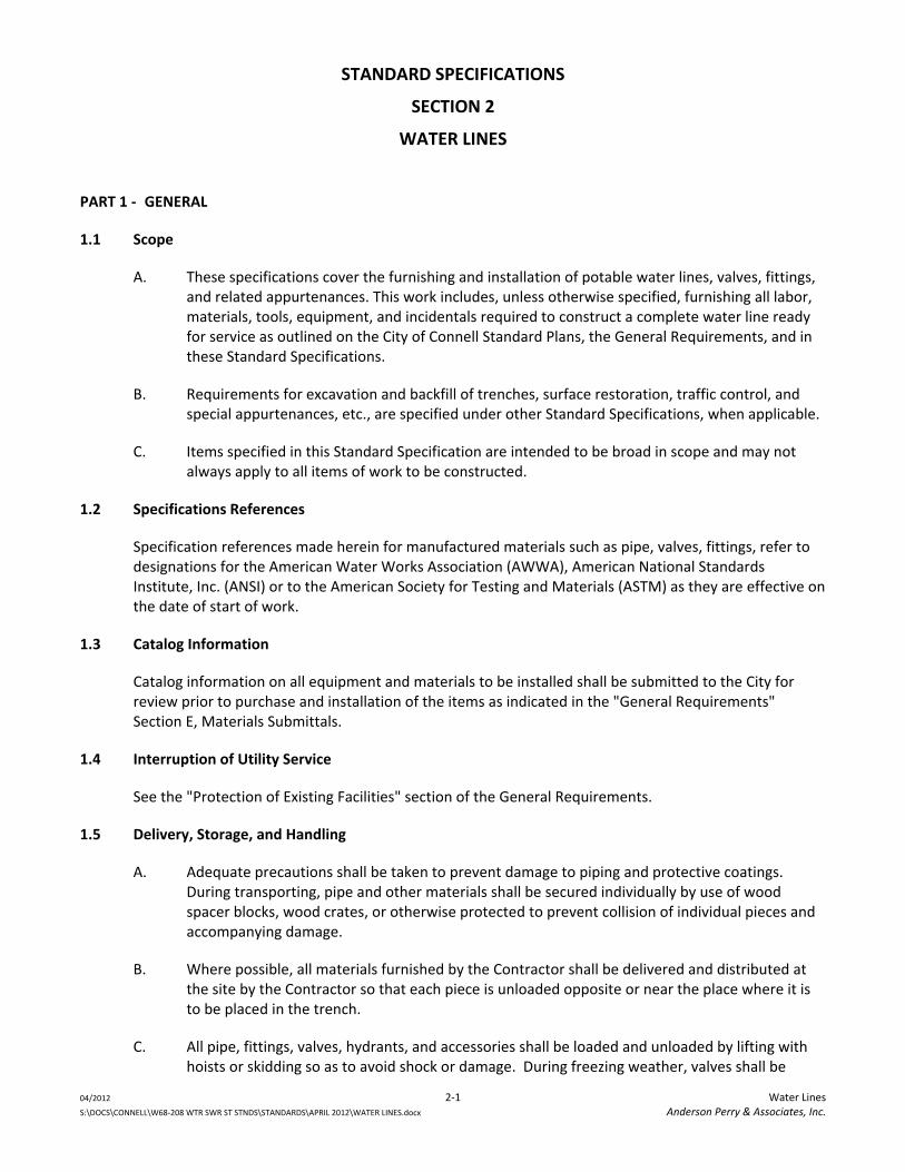
PART 1 ‐ GENERAL
1.1 Scope
A. These specifications cover the furnishing and installation of potable water lines, valves, fittings, and related appurtenances. This work includes, unless otherwise specified, furnishing all labor, materials, tools, equipment, and incidentals required to construct a complete water line ready for service as outlined on the City of Connell Standard Plans, the General Requirements, and in these Standard Specifications.
B. Requirements for excavation and backfill of trenches, surface restoration, traffic control, and special appurtenances, etc., are specified under other Standard Specifications, when applicable.
C. Items specified in this Standard Specification are intended to be broad in scope and may not always apply to all items of work to be constructed.
1.2 Specifications References
Specification references made herein for manufactured materials such as pipe, valves, fittings, refer to designations for the American Water Works Association (AWWA), American National Standards Institute, Inc. (ANSI) or to the American Society for Testing and Materials (ASTM) as they are effective on the date of start of work.
1.3 Catalog Information
Catalog information on all equipment and materials to be installed shall be submitted to the City for review prior to purchase and installation of the items as indicated in the "General Requirements" Section E, Materials Submittals.
1.4 Interruption of Utility Service
See the "Protection of Existing Facilities" section of the General Requirements.
1.5 Delivery, Storage, and Handling
A. Adequate precautions shall be taken to prevent damage to piping and protective coatings. During transporting, pipe and other materials shall be secured individually by use of wood spacer blocks, wood crates, or otherwise protected to prevent collision of individual pieces and accompanying damage.
B. Where possible, all materials furnished by the Contractor shall be delivered and distributed at the site by the Contractor so that each piece is unloaded opposite or near the place where it is to be placed in the trench.
C. All pipe, fittings, valves, hydrants, and accessories shall be loaded and unloaded by lifting with hoists or skidding so as to avoid shock or damage. During freezing weather, valves shall be
STANDARD SPECIFICATIONS
SECTION 2
WATER LINES
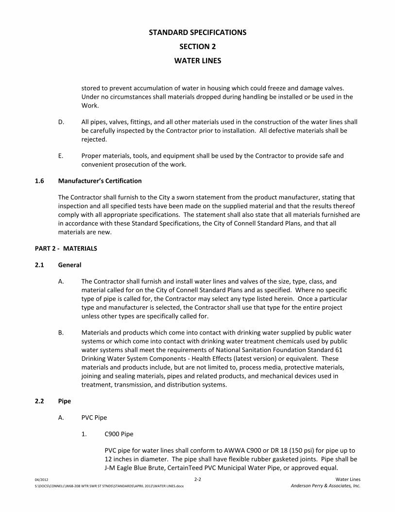
04/2012 2‐2 Water Lines S:\DOCS\CONNELL\W68‐208 WTR SWR ST STNDS\STANDARDS\APRIL 2012\WATER LINES.docx Anderson Perry & Associates, Inc.
stored to prevent accumulation of water in housing which could freeze and damage valves. Under no circumstances shall materials dropped during handling be installed or be used in the Work.
D. All pipes, valves, fittings, and all other materials used in the construction of the water lines shall be carefully inspected by the Contractor prior to installation. All defective materials shall be rejected.
E. Proper materials, tools, and equipment shall be used by the Contractor to provide safe and convenient prosecution of the work.
1.6 Manufacturer’s Certification
The Contractor shall furnish to the City a sworn statement from the product manufacturer, stating that inspection and all specified tests have been made on the supplied material and that the results thereof comply with all appropriate specifications. The statement shall also state that all materials furnished are in accordance with these Standard Specifications, the City of Connell Standard Plans, and that all materials are new.
PART 2 ‐ MATERIALS
2.1 General
A. The Contractor shall furnish and install water lines and valves of the size, type, class, and material called for on the City of Connell Standard Plans and as specified. Where no specific type of pipe is called for, the Contractor may select any type listed herein. Once a particular type and manufacturer is selected, the Contractor shall use that type for the entire project unless other types are specifically called for.
B. Materials and products which come into contact with drinking water supplied by public water systems or which come into contact with drinking water treatment chemicals used by public water systems shall meet the requirements of National Sanitation Foundation Standard 61 Drinking Water System Components ‐ Health Effects (latest version) or equivalent. These materials and products include, but are not limited to, process media, protective materials, joining and sealing materials, pipes and related products, and mechanical devices used in treatment, transmission, and distribution systems.
2.2 Pipe
A. PVC Pipe
1. C900 Pipe
PVC pipe for water lines shall conform to AWWA C900 or DR 18 (150 psi) for pipe up to 12 inches in diameter. The pipe shall have flexible rubber gasketed joints. Pipe shall be J‐M Eagle Blue Brute, CertainTeed PVC Municipal Water Pipe, or approved equal.
STANDARD SPECIFICATIONS
SECTION 2
WATER LINES
04/2012 2‐3 Water Lines S:\DOCS\CONNELL\W68‐208 WTR SWR ST STNDS\STANDARDS\APRIL 2012\WATER LINES.docx Anderson Perry & Associates, Inc.
2. C905 Pipe
PVC pipe shall conform to AWWA C905, DR 25 (165 psi) for pipe from 14 inches to 30 inches in diameter. The pipe shall have flexible rubber gasketed joints. Pipe shall be J‐M Eagle Big Blue, Diamond Plastics Trans‐21, or approved equal.
B. Ductile Iron Pipe
1. Ductile iron pipe and fittings shall conform to AWWA C150, AWWA C115, AWWA C151, AWWA C153, and AWWA C110 and shall be minimum pressure Class 350 unless specified otherwise.
2. All ductile iron pipe shall have a bituminous sealed cement mortar lining conforming to AWWA C104 on the interior.
3. All joints unless otherwise specified shall be push‐on rubber gasket joints conforming to AWWA C111 and shall be furnished complete with all necessary accessories.
a. Flanges for couplings and fittings shall conform to ANSI B16.1, 125 pound bolt hole template.
b. Mechanical joints shall conform to AWWA C111.
4. When flanged pipe is required, the Contractor shall provide the D.I. pipe class required by the flange manufacturer to ensure the pipe and flange units are compatible. This data shall be provided to the City for review prior to ordering these materials.
C. High Density Polyethylene Tubing for Service Lines
1. HDPE pipe shall be made from polyethylene resin compound with a minimum cell classification of PE 445574C, or approved equal for PE 4710 materials in accordance with ASTM D 3350. This material shall have a Hydrostatic Strength of 1,600 psi when tested and analyzed by ASTM D 2837, and shall be a Plastic Pipe Institute (PPI) listed compound. The raw material for the pipe shall contain a minimum of 2 percent, well dispersed, carbon black.
2. IPS Pipe for sizes 3/4‐inch through 2‐inch shall be minimum SDR 9, Class 200 CTS size manufactured in accordance with AWWA C901 and to the requirements of ASTM D‐2737 (CTS).
STANDARD SPECIFICATIONS
SECTION 2
WATER LINES
04/2012 2‐4 Water Lines S:\DOCS\CONNELL\W68‐208 WTR SWR ST STNDS\STANDARDS\APRIL 2012\WATER LINES.docx Anderson Perry & Associates, Inc.
2.3 Fittings for Iron and PVC Pipe
A. General
1. Unless specified otherwise, all fittings such as elbows, tees, crosses, valves, etc., shall have mechanical joints conforming to AWWA C111 and shall be short‐bodied compact ductile iron fittings conforming to AWWA C153, Class 350.
2. When called for, flanged cast iron fittings shall conform to AWWA C110 with ANSI B16.1, 125‐pound bolt hole template.
3. All fittings shall be cement mortar lined in accordance with AWWA C104.
4. Gaskets shall be either ring or full faced, 1/8‐inch thick conforming to AWWA C111, Appendix B.
B. Fitting and Joint Restraint
1. General. All fittings and pipe joints requiring restraint shall be restrained by mechanical means unless otherwise shown on the drawings or allowed by the Engineer. All changes in directions (both horizontal and vertical), all dead ends, and pipe joints within the distances from fittings specified by the Engineer on the drawings shall be restrained.
2. Fitting Restraint. Ductile iron fittings shall be restrained by using flanged fittings or by using mechanical joints with approved mechanical restraining devices such as the MEGALUG® series by EBBA Iron or equal.
3. Pipe Joint Restraint. Ductile iron pipe joints shall be restrained with field installed restraining gaskets such as FIELDLOK™ gasket system as manufactured by United States Pipe and Foundry Company or approved equal. PVC pipe joints shall be restrained with a restraining harness such as EBBA Iron 1500 or 1600 series harness for NWWA C900 pipe or series 1100HV for AWWA C905 pipe or equal.
C. Water Main Couplings
1. Water main couplings shall be fabricated steel “Dresser” style couplings, or approved equal, conforming to AWWA C219.
2. The Contractor shall provide the appropriate coupling and gaskets as required to match the water lines types and sizes being utilized.
3. Couplings shall be rated for the working pressure of the pipe main for which they will be utilized.
STANDARD SPECIFICATIONS
SECTION 2
WATER LINES
04/2012 2‐5 Water Lines S:\DOCS\CONNELL\W68‐208 WTR SWR ST STNDS\STANDARDS\APRIL 2012\WATER LINES.docx Anderson Perry & Associates, Inc.
2.4 Valves
A. Gate Valves
1. Gate valves 2 inches and smaller shall be all bronze, non‐rising stem, conforming to Federal Specification WW‐V‐54, Type I, Class A and MSS SP‐80, Class A rated for a minimum working pressure of 125 psi.
2. Gate valves 2 1/2‐inch to 12‐inch shall conform to AWWA C509 or C515. Valves shall be designed for 200 psi minimum working pressure and shall be of iron body, resilient wedge, non‐rising stem construction. Valves shall be equipped with O‐ring type packing. The valve shall have a 2‐inch AWWA operating nut for buried service or as directed by the City. The valve ends shall be of the type required to match the pipe to which they will be connected. Valves shall have mechanical joint connections, unless called for otherwise by the City. Valves shall be resilient wedge, Kennedy KSRW or KSFW, Ken‐Seal II, M&H Style 4067 or 7000, Clow, or equal.
3. Gate valves 14‐inch and 16‐inch shall meet or exceed the requirements of AWWA C509 and shall also conform to the applicable requirements of AWWA C500. Valves shall be designed for 200 psi minimum working pressure and shall be of iron body, resilient wedge, non‐rising stem construction. Valves shall be equipped with O‐ring stem seal. The valve shall have a 2‐inch AWWA operating nut. The valve ends shall be of the type required to match the pipe to which they will be connected or as directed by the City. Valves shall be Metroseal 250 as manufactured by U.S. Pipe or equal.
4. Gate valves 18 inches and larger shall conform to AWWA C‐500. Valves shall be designed for 150 psi minimum working pressure and shall be of iron body, double disk, parallel seat, bronze mounted, non‐rising stem construction. Valves shall be equipped with O‐ring type packing. The valve shall have a 2‐inch AWWA operating nut. The valve ends shall be of the type required to match the pipe to which they will be connected. Valve shall be M&H NRS Style 67 or equal.
B. Ball Valves
Ball valves 2 inches and smaller shall be bronze, conforming to Federal Specification WW‐V‐35, Type II, Class A, Style 3, rated for a minimum working pressure of 125 psi.
C. Butterfly Valves
1. All butterfly valves shall be of the rubber‐seated tight‐closing type that shall meet or exceed the requirements of AWWA C504. All valves shall be M&H 4500, Clow 4500, or approved equal.
2. The valve shall be for buried service with a sealed gear operator having 2‐inch AWWA operating nut and shall open counter‐clockwise.
STANDARD SPECIFICATIONS
SECTION 2
WATER LINES
04/2012 2‐6 Water Lines S:\DOCS\CONNELL\W68‐208 WTR SWR ST STNDS\STANDARDS\APRIL 2012\WATER LINES.docx Anderson Perry & Associates, Inc.
3. The valve ends shall be of type required to match the pipe to which they will be connected.
D. Cast Iron Valve Box
1. Each valve shall be equipped with an adjustable cast iron box of the sliding type with a base large enough to cover the top casting of the valve.
2. The diameter of the valve box shall be not less than five (5) inches, and shall be of such length so as to provide the depth of cover over the pipe without full extension.
2.5 Fire Hydrants
A. Fire hydrants shall conform to AWWA C502 and shall have 5‐1/4‐inch main valve opening, two 2‐1/2‐inch NST nozzles and one 4‐1/2‐inch NST pumper nozzle. Operating nut shall be 1‐1/2‐inch pentagon. Fire hydrants shall be Clow Medallion 2500 or M&H 929. No other hydrants will be considered.
B. All hydrants shall have a minimum depth of bury of 42 inches. Where conditions require, hydrant extensions shall be provided and installed to provide the proper placement and installation of the hydrant.
C. Hydrants shall receive factory coats of OSHA, Safety Yellow enamel paint and shall also receive an additional field coat after installation.
D. All hydrants shall be of the traffic model type.
2.6 Combination Air Release Valves
Air Release Valves shall be a combination air and vacuum type such as APCO No. 143 C or ValMatic No. 201C, or approved equal, with 2‐inch inlet and designed for 150 psi operating pressure.
2.7 Service Saddles
A. Service saddles shall have a ductile iron body, wide stainless steel band, and stainless steel bolts and nuts. Service saddles shall be Ford FS101 style for 3/4‐inch and 1‐inch taps and Ford FS202 for all taps larger than 1 inch, or approved equal.
B. Saddle sizes and threads shall be compatible with the pipe type and sizes being utilized.
C. Service saddles are not required for ductile iron pressure class pipe for taps 1‐inch and less. Service saddles are required for ductile iron pressure class pipe for taps greater than 1‐inch. Service saddles used on PVC water mains shall be specifically sized at the factory for the type of PVC water main used.
STANDARD SPECIFICATIONS
SECTION 2
WATER LINES
04/2012 2‐7 Water Lines S:\DOCS\CONNELL\W68‐208 WTR SWR ST STNDS\STANDARDS\APRIL 2012\WATER LINES.docx Anderson Perry & Associates, Inc.
2.8 Corporation Stops
A. Corporation stops shall be brass ball valve stops complying with AWWA C‐800. Corporation stops shall be Ford ball corp or approved equal.
B. Inlet threads and outlet connections shall be as required for type and size of water service lines and service saddles being utilized.
2.9 Curb Stops
A. Curb stops shall be Ford brass ball valves or approved equal.
B. Valve configuration, inlet, and outlet requirements shall be as required for the size and type of water service lines.
2.10 Service Line Couplings
A. Service line couplings shall be Ford pack joint couplings or approved equal.
B. Provide appropriate coupling as required to match water service lines types and sizes being utilized. Appropriate stainless steel insert stiffeners shall be used for all PVC pipe and polyethylene tubing.
C. Where metal pipe of dissimilar type are being connected, an insulating adaptor gasket such as Dresser Style 65, or approved equal, shall be utilized to prevent galvanic corrosion.
2.11 Curb Stop Box
A. Each curb stop shall be equipped with an adjustable cast iron box of the sliding type and shall be of such length so as to provide the depth of cover over the pipe without full extension.
B. The curb stop box shall be equal to Ford Arch Pattern Curb Boxes with 1‐inch upper section and stationary rod and Type PS plug style lid with pentagon bolt, or approved equal.
C. For service curb stops larger than 1‐inch, a curb box base, Ford CB‐7, shall also be provided.
2.12 Meter Setters
A. Meter setters for 1‐inch and smaller meters shall be Ford 40 Series copper setter approved equal.
B. Meter setters for 1‐1/2‐inch or 2‐inch water meters shall be Ford 40 Series copper setters or approved equal.
C. A Ford angle meter ball valve shall be provided on the meter inlet and a Ford cartridge check valve shall be provided on the meter outlet.
STANDARD SPECIFICATIONS
SECTION 2
WATER LINES
04/2012 2‐8 Water Lines S:\DOCS\CONNELL\W68‐208 WTR SWR ST STNDS\STANDARDS\APRIL 2012\WATER LINES.docx Anderson Perry & Associates, Inc.
D. Provide appropriate meter setter heights, sizes, and connections, etc., as required for the meter and water service lines sizes and types being utilized.
E. Schedule 40 PVC 1‐inch pipe shall also be installed in the setter pipe eyelets to increase the stability of the meter setting.
2.13 Automated Metering Reading (AMR) System
A. Water Meters
1. Water meters for 3/4‐, 1‐, 1‐1/2‐, and 2‐inch sizes shall be Neptune Model T‐10 with E‐Coder R900i register.
2. For 3‐inch size, the meter shall be Neptune HP turbine meter with AMR.
3. Meters shall meet or exceed the requirements of AWWA C700 latest revision. All meters 2 inch and smaller shall read in cubic feet and meters larger than 2 inch shall read in gallons.
4. All meters shall be short lay 3/4" size unless specifically called for otherwise or required by the City. Provide one flanged 3‐inch idler pipe to the City.
B. The Electronic Communication Register (ECR) shall be included with each meter size and shall include the touch or inductive pad.
2.14 Water Meter Box and Cover
A. Water meter boxes for 1‐inch and smaller meters shall be a 13‐inch x 24‐inch polyethylene box with recessed lid as manufactured by Raven Products, LLC. The lids shall include a hinged cast iron reader lid and a recessed area for AMR/radio read. Other box manufacturers may be used if approved by the City. Approval will only be granted if the Owner is satisfied that the alternate box and lid are equal or better.
B. Meter box covers shall properly fit the meter box provided. Traffic rated lids shall be provided in areas designated by the Owner.
C. Water meter boxes for 1 1/2‐inch and 2‐inch meters shall be a 17‐inch x 30‐inch polyethylene box with recessed lid as manufactured by Raven Products, LLC. The lids shall include a hinged cast iron reader lid and a recessed area for AMR/radio read. Approval will only be granted if the Owner is satisfied that the alternate box and lid are equal or better.
STANDARD SPECIFICATIONS
SECTION 2
WATER LINES
04/2012 2‐9 Water Lines S:\DOCS\CONNELL\W68‐208 WTR SWR ST STNDS\STANDARDS\APRIL 2012\WATER LINES.docx Anderson Perry & Associates, Inc.
2.15 Locating Wire
A. Locating wire shall be a minimum of 12 awg UF solid copper with blue colored insulation. The use of THHN wire will not be acceptable. The silicone splice kit shall be King Technology Model 50‐566 or approved equal.
B. Where location wire is to be secured to the exterior of fire hydrants, valve boxes, posts, etc., stainless steel pipe straps shall be used.
2.16 Thrust and Anchor Blocks and Concrete Collars
A. Concrete used for thrust and anchor blocks, and concrete collars shall be Portland Cement concrete with a 28‐day compressive strength of 2500 psi.
B. Anchor rods shall be 3/4‐inch diameter galvanized steel or epoxy coated reinforcement bar conforming to AASHTO M284, embedded a minimum of 18 inches in the concrete.
2.17 Water Line Blowoff/Flush Type Hydrant
Flush type fire hydrant/blowoff shall be a dry barrel type with a 2 1/8‐inch main valve opening and one 2 1/2‐inch hose nozzle. The box shall have a non‐locking lid. All applicable parts shall comply with AWWA C502. The hydrant shall be a Mueller Co. 2 1/8” flush type hydrant, or approved equal.
PART 3 ‐ EXECUTION
3.1 Trench Excavation and Backfill
Trench excavation and backfill shall be performed as specified in the Standard Specifications for "Excavation and Backfill of Trenches" and the City of Connell Standard Plans.
3.2 Sequence of Water Line Work
A. The following is a general outline of the sequencings of the water line work. When more than a few blocks of water line are involved, the project shall be divided into multiple work zones and the sequence repeated for each area.
1. Pothole connection points and crossings to verify pipe size, type, and depth.
2. The Contractor shall obtain water shutoff tags from the City and provide the notices to all water users expected to be impacted by the water shutoff. Notices shall be distributed no later than 4:00 p.m. the day before the work is to be done.
3. Excavate and inspect the existing water lines and verify all required fittings are on site.
4. With the assistance of the City, shut off the necessary valves to isolate the existing water line.
STANDARD SPECIFICATIONS
SECTION 2
WATER LINES
04/2012 2‐10 Water Lines S:\DOCS\CONNELL\W68‐208 WTR SWR ST STNDS\STANDARDS\APRIL 2012\WATER LINES.docx Anderson Perry & Associates, Inc.
5. Once the connection is made, the existing water main shall be placed back into service.
6. New water mains shall be installed, disinfected, pressure tested, and flushed.
7. New service lines shall be installed, flushed, and connected to the existing service lines as shown on the plans.
8. Complete the abandonment of existing water lines that are being replaced. Install blind flanges, end caps, etc. at designated or required areas.
9. Remove abandoned hydrants and valves as identified and deliver them to the City Shop.
10. Complete surface restoration.
3.3 Record Drawings
The requirements for Record Drawings, etc., shall be as required in the General Requirements.
3.4 Installation of Pipe
A. Water pipe shall be installed in accordance with best current practices as required by the manufacturer and as specified herein. PVC pipe installation shall conform to the Uni‐Bell Plastic Pipe Association, "Guide for Installation of PVC Pressure Pipe for Municipal Water Main Distribution Systems" and also AWWA M23 "PVC Pipe ‐ Design and Installation." Ductile iron pipe installation shall conform to the requirements of AWWA C600.
B. Water pipe shall be installed with bell ends laid facing in the direction of laying unless directed otherwise by the City. Each pipe shall be properly bedded so as to be supported for the full length of the pipe. A suitable foundation shall be achieved by a slight excavation under the bell at each joint. All rubber ring joints shall be lubricated and installed in accordance with the installation instructions of the pipe manufacturer, taking particular care to avoid pinching or otherwise causing damage to the rubber ring. All joints shall be free of dirt and other foreign matter prior to the joining of the next pipe. All joints shall be restrained to prevent creep and misalignment of joints.
C. Water lines shall be installed to the minimum depths called for on the City of Connell Standard Plans.
1. It shall be recognized that water line depths may vary from the minimum depths shown when adjustment of grade is required to avoid conflict with existing utilities.
2. Additional fittings may also be required when a grade adjustment is required.
STANDARD SPECIFICATIONS
SECTION 2
WATER LINES
04/2012 2‐11 Water Lines S:\DOCS\CONNELL\W68‐208 WTR SWR ST STNDS\STANDARDS\APRIL 2012\WATER LINES.docx Anderson Perry & Associates, Inc.
D. No pipe shall be installed in water or when conditions exist that, in the opinion of the City, are unsuitable for the laying of the pipe.
1. At times when pipe laying is not in progress, the open ends of pipe shall be closed by a watertight plug or other approved means. This provision applies during the noon hour as well as overnight.
2. If there is water in the trench, the seal should remain in place until the trench is dewatered sufficiently to prevent groundwater from entering the pipe. Adequate provisions shall be made by the Contractor for final disposal of the groundwater pumped from trenches.
E. All pipe shall be installed true to line. The Contractor may install a pipeline on a curve when approved by the City.
1. For rubber gasketed ductile iron pipe installed on a curve, the pipe shall be joined in a straight alignment, then deflected. The amount of deflection shall not exceed 80 percent of the recommended maximum deflection specified in AWWA C600.
2. For PVC pipe installed on a curve, deflection of the pipe shall be achieved by bending the pipe within the limitations specified by the pipe manufacturer. Joint deflection of PVC pipe is not allowed.
3.5 Thrust and Anchor Blocks
A. Thrust and anchor blocks shall be used when existing conditions do not allow the use of mechanical restraints and shall be constructed as shown on the City of Connell Standard Plans and placed at all changes in direction, all changes in the diameter of the pipe, all dead‐ends, as specifically shown in the City of Connell Standard Plans and as required by the City.
B. All thrust blocks shall be placed between the undisturbed ground and the fitting to be anchored. Plastic sheeting shall be used to provide a bonding barrier between the fittings and the concrete. The quantity of concrete and the area of bearing on the soil shall be as shown on the City of Connell Standard Plans and as approved by the City.
C. All thrust blocks shall be placed so that the entire pipe and fitting joints will be accessible for repairs. Bolts for mechanical and flange fittings and fire hydrant weep holes shall not be covered with concrete. All bolts shall be accessible and removable without interference from the thrust block.
D. No backfill of thrust blocks shall occur until the work has been inspected by the City.
STANDARD SPECIFICATIONS
SECTION 2
WATER LINES
04/2012 2‐12 Water Lines S:\DOCS\CONNELL\W68‐208 WTR SWR ST STNDS\STANDARDS\APRIL 2012\WATER LINES.docx Anderson Perry & Associates, Inc.
3.6 Locating Wire
A. A continuous solid copper locating wire shall be placed along the top of all water pipe, including service lines. This wire shall be secured to the top of the pipe at maximum 10‐foot intervals using 6‐inch strips of 2‐inch wide duct tape. All splices shall be electrically continuous. At all splices the connecting ends of the wires shall be overlapped and tied. The ends shall be stripped and connected with a wire nut to ensure an electrical connection and made waterproof with an approved silicone splice kit. Access to terminal ends of the locating wire shall be made at all valve boxes, meter boxes, fire hydrants, vaults, etc. The result of this installation shall be a continuous wire circuit electrically isolated from ground.
B. The Contractor shall be responsible for testing continuity and for testing isolation from ground in the wire after all work has been completed on the test section. The Contractor is advised to do intermediate testing on his own after backfilling operations and prior to surface restoration work to be sure continuity is maintained. If there is a break or defect in the wire, it shall be the Contractor's responsibility to locate and repair the defect.
C. The continuity of the location wire shall be tested from one test load point to the next by use of a temporary wire laid between test points in‐line with an ohmmeter. Resistance shall be measured with an approved ohmmeter that has been properly calibrated. The continuity of a test section will be accepted if the resistance of the test section does not exceed 5 ohms per 500 feet of location wire being tested. Isolation from ground shall be measured with a megohmmeter and shall be a minimum of 20 megohms for any section of location wire tested. The City shall witness the acceptance test. The wire and installation shall be included in the water line bid price. No separate payment shall be made.
3.7 Service Connections
The Contractor shall connect service lines to new or existing water mains as shown on the City of Connell Standard Plans. This work includes the installation of a saddle and corporation stop, and making the connection. The work will include potholing to locate any existing pipeline or service lines as required so the service connection can be performed.
3.8 Service Lines
A. The installation of new service lines and the connecting of existing service lines shall be performed in accordance with the City of Connell Standard Plans, manufacturer requirements, and as specified herein. Water service lines shall be laid by placing the pipe on the trench bottom with sufficient slack to prevent pulling apart of the joints when the backfill is placed. Splices shall be kept to an absolute minimum. If required, they shall be made using brass compression joint couplings, Ford Pack Joint or approved equal.
B. When constructing a new water line to replace an existing line, the existing water line shall remain in service until the new water line has been tested, disinfected and approved by the City. When possible, the existing line and new line shall both be in operation during the transfer of service lines. The transfer shall be made so that the interruption of water service to the utility
STANDARD SPECIFICATIONS
SECTION 2
WATER LINES
04/2012 2‐13 Water Lines S:\DOCS\CONNELL\W68‐208 WTR SWR ST STNDS\STANDARDS\APRIL 2012\WATER LINES.docx Anderson Perry & Associates, Inc.
customer is held to a minimum. All service lines shall be thoroughly flushed before connecting to existing lines or meters.
3.9 Valves and Valve Boxes
A. Valves and valve boxes shall be installed as shown in the City of Connell Standard Plans. All valves and valve boxes shall be set plumb. The valve box shall be centered over the valve operator and free of any obstruction which would prevent operation of the valve nut.
B. If the bury depth of the valve is greater than 4 1/2 feet, a valve operator extension shall be provided to within 1 foot of finish grade. The extension shall be permanently attached to the valve operator and a self‐centering device shall be provided near the top of the valve operator extension. The box cover shall be installed with a concrete collar and adjusted to final grade as shown on the City of Connell Standard Plans.
3.10 Fire Hydrants
A. Hydrant installation shall conform with AWWA Manual M17 and AWWA C600, and as shown on the City of Connell Standard Plans. Extensions required for hydrant adjustment shall be installed to the manufacturer's specifications.
B. Hydrants may be installed on new water mains installed as part of the work, or on existing mains. Special attention shall be given when installing hydrants on existing mains to ensure that adequate thrust restraint is being achieved as the hydrants can be placed in service before normal cast‐in‐place thrust blocks can achieve the required strength. The block and plug shall be held securely by temporary thrust block or other approved method, such as precast thrust blocks, restraining rods, etc.
C. The newly installed hydrants shall be covered in a manner acceptable to the City until they are placed into permanent service.
D. Apply field coat of paint.
3.11 Removal of Existing Fire Hydrants
A. All hydrants removed shall remain the property of the City and shall be delivered and properly stacked at a site designated by the City.
B. After the old hydrant is removed, the lead line, if it is to be abandoned, shall be plugged at the main line tee with a watertight plug and thrust block. When the lead pipe is connected to a water main which is being abandoned, it will not need to be plugged.
C. The Contractor shall apply black paint to the hydrant the same day the existing hydrant is disconnected from service; or otherwise, mark the hydrant in a manner acceptable to the City.
STANDARD SPECIFICATIONS
SECTION 2
WATER LINES
04/2012 2‐14 Water Lines S:\DOCS\CONNELL\W68‐208 WTR SWR ST STNDS\STANDARDS\APRIL 2012\WATER LINES.docx Anderson Perry & Associates, Inc.
3.12 Water Line Blowoffs
The 2‐inch water line blowoffs shall be constructed as shown on the City of Connell Standard Plans.
3.13 Connections to Existing Lines
A. In connecting to existing lines, the Contractor may select the combination of fittings he wishes to use, subject to approval of the City. Approved fabricated steel couplings, repair bands, transition couplings, or tapping sleeves are among the options available to the Contractor. The Contractor shall submit to the City information on the type of couplings he proposes to use.
B. Proper disinfection, as described hereafter, shall always be accomplished. The Contractor shall provide watertight plugs and thrust restraints, as required, to cap old lines after they are disconnected.
C. The Contractor shall provide special attention in providing thrust restraint for fittings installed as part of a connection to an existing line, when such connection will be placed into service before normal cast‐in‐place thrust blocks can achieve required strength. In such cases thrust restrained joints, precast thrust blocks, etc., must be utilized to provide thrust restraint. Methods used by the Contractor shall be approved by the City.
D. The Contractor shall not interrupt service for the purpose of connecting to an existing line until he has excavated the required location, visually inspected the connection point, and verified that he has available on the site all fittings required for completion of the connection or connections. Isolation of a section of line to be modified will be accomplished by the Contractor only after consultation with the City for the purpose of determining the proper valves to close to effect the isolation. The Contractor shall cooperate with the City in accomplishing this isolation. When work is started on a connection, it shall proceed continuously without interruption, and as rapidly as possible until completed. If the connection involves turning off the water, the Contractor shall be responsible for notifying the residents affected by the shutoff. See the "Protection of Existing Facilities" section of the General Requirements.
3.14 Water Meter Installation
The Contractor shall furnish all materials required and shall install the water meters as shown on the City of Connell Standard Plans and described herein. Water meter installations shall include appropriate meter box and cover, copper setter, yokes, and fittings, and shall include the water meter when meter is not to be installed by the City. Meter boxes shall be set plumb with cover level and with equal clearance on all sides between the box and the plumbing.
STANDARD SPECIFICATIONS
SECTION 2
WATER LINES
04/2012 2‐15 Water Lines S:\DOCS\CONNELL\W68‐208 WTR SWR ST STNDS\STANDARDS\APRIL 2012\WATER LINES.docx Anderson Perry & Associates, Inc.
3.15 Water‐Sewer Line Crossings
A. Wherever possible, the bottom of the new water line shall be 1.5 feet or more above the top of any sanitary sewer line. The minimum requirements for water/sewer separation set by the Washington State Department of Ecology’s criteria for sewage works design shall be met at all times.
B. Where the water line crosses over an existing sanitary sewer line but with a clearance of less than 1.5 feet, the sewer line shall be exposed to the sewer line joints on both sides of the crossing to permit examination of the sewer pipe.
1. If the sewer pipe is in good condition and there is no evidence of leakage from the sewer line as observed by the City, the 1.5‐foot separation may be reduced by the City.
2. When the vertical separation is less than 1.5 feet, the Contractor shall center one full length of the new water pipe over the sewer line.
3. If the City determines that the conditions are not favorable or finds evidence of leakage from the sewer line, the sewer line shall be replaced with a full length of PVC pressure pipe (AWWA C900, DR 18, 150 psi pipe) centered at the crossing point.
C. Where the water line crosses under the sanitary sewer line, the Contractor shall expose the existing sewer line and examine it as indicated above.
1. If conditions are favorable and there is no evidence of leakage from the sewer line, the sewer line may be left in place but must be supported with a steel beam, reinforced concrete beam, or other means of preventing settlement when it spans the water line trench, and special precautions must be taken to assure that the backfill material over the water line in the vicinity of the crossing is thoroughly compacted in order to prevent settlement which could result in the leakage of sewage. In this situation, the Contractor shall center one length of the new water line at the crossing.
2. If the City determines that conditions are not favorable or finds evidence of leakage from the sewer line, then the sewer line at the crossing shall be replaced.
D. When constructing water service lines, the City may require the depth of the service line to be revised in order to eliminate the need for a water‐sewer line crossing.
STANDARD SPECIFICATIONS
SECTION 2
WATER LINES
04/2012 2‐16 Water Lines S:\DOCS\CONNELL\W68‐208 WTR SWR ST STNDS\STANDARDS\APRIL 2012\WATER LINES.docx Anderson Perry & Associates, Inc.
3.16 Capping Existing Water Mains and Services
A. When required, the Contractor shall cap an existing water main or service tap when an existing main or service is to be taken out of service. Each location will require different types of fittings, etc., to accomplish the work. All caps are to be permanent and watertight. When required, thrust restraints shall be provided. Corporation stops on service taps shall be in "off" position and an approved watertight cap installed.
B. Unless specified otherwise, the capping shall be performed at the connection to the water main which is to remain in service. No stubbed water mains or service lines shall be left in the ground unless approved otherwise by the City. The Contractor shall excavate and expose the piping to be capped, perform the work, and backfill as required.
3.17 Abandoned Water Lines
A. The existing water lines to be taken out of service are to remain in service until the new lines are properly installed and tested, and water services have been connected. Approval from the City shall be obtained before any line is abandoned.
B. The existing lines shall then be abandoned and their actual location and abandoned designation recorded on all Record Drawings.
C. Unless called for otherwise, the abandoned lines will remain in the ground. The ends of all pipes which are abandoned shall be plugged with concrete or other methods approved by the City.
3.18 Air Release Valves
Air release valves shall be installed as required by the manufacturer.
3.19 Other Installations
Installations of valves and valve boxes shall be in accordance with the manufacturer requirements and the City of Connell Standard Plans.
3.20 Removal and Salvage of Water Main Appurtenances, Fittings, and Other Items
A. The Contractor shall remove all existing valves, hydrants, and fittings as required to properly perform the work. All such materials shall be transported to an area designated by the City and stockpiled. Materials shall be removed and handled in such a manner which will prevent damage.
B. The abandoned existing pipe is to remain in the ground, unless otherwise specified.
STANDARD SPECIFICATIONS
SECTION 2
WATER LINES
04/2012 2‐17 Water Lines S:\DOCS\CONNELL\W68‐208 WTR SWR ST STNDS\STANDARDS\APRIL 2012\WATER LINES.docx Anderson Perry & Associates, Inc.
3.21 Work with Existing Asbestos Cement (A/C) Pipe
A. When working with A/C pipe, the Contractor shall take all precautions necessary to reduce airborne asbestos during construction. All work with A/C pipe shall conform with American Water Works Association Publication No. M16 "Work Practices for Asbestos‐Cement Pipe."
B. The Contractor shall cut asbestos cement pipe by using snap cutters only. The use of carbide‐tipped cutting blades or high speed, abrasive disks shall not be permitted as a means of cutting A/C pipe snap cutters. Machining of this pipe shall be done with a manual or power‐driven field lathe, or with a manual rasp.
C. Hole cutting shall be accomplished with a tapping machine. Use of shell cutters, rasps, chisels, electric drills, right angle sanders, or other high speed abrasive tools shall not be permitted. Uncoupling of asbestos cement pipe shall be accomplished with a hammer and chisel. Use of abrasive disc cutters, right angle sanders, or other high speed abrasive tools shall not be permitted.
D. Dust and cuttings from all work shall be removed by wet mopping.
E. All waste material shall be collected in a covered container and disposed at a landfill certified by the state or EPA to accept demolition waste.
3.22 Repair of Unmarked Water Lines
A. The specific location, pipe size, type and bury depth of every existing water main and service may not be known. Prior to construction, the City will mark the location of known water lines with paint.
B. The Contractor shall perform appropriate exploratory work to locate utilities when they are known to exist but the specific location is unknown or not marked accurately.
C. Contractor shall repair the water main or service coupling using materials approved by the City.
3.23 Water Marker Posts
The Contractor shall furnish and place marker posts at locations as directed by the City to mark the locations of certain valves and other appurtenances. Posts shall be set solidly in the ground.
STANDARD SPECIFICATIONS
SECTION 2
WATER LINES
04/2012 2‐18 Water Lines S:\DOCS\CONNELL\W68‐208 WTR SWR ST STNDS\STANDARDS\APRIL 2012\WATER LINES.docx Anderson Perry & Associates, Inc.
3.24 Testing and Disinfection
A. General. The Contractor shall furnish all necessary equipment and other apparatus, including gauges, necessary to properly perform the testing and disinfection of water lines as specified. Lines to be tested include mains and service lines. Each section of the lines before being tested and placed into service shall be isolated and slowly filled with water. Air should be expelled from the line through hydrants or taps made at the high points. The City shall have the option of requiring the use of his own gauges. Water mains shall be generally tested in sections between valves and as the work progresses. The Contractor shall be responsible for determining the length, timing, and section of lines to be tested, unless otherwise noted. When appropriate, testing intermediate sections of long lines should be considered. The Contractor shall provide any temporary test heads, fittings, blocking, etc., as may be required to properly test any given water main section. The Contractor shall be responsible for locating and repairing any defects in the water mains which fail to pass the required test.
B. Acceptance Test. The Contractor shall perform all preliminary testing required to determine that the lines to be tested are acceptable and comply with the requirements of this section of the Specifications. After the Contractor has determined that the lines will pass the required test, the Contractor shall arrange for an acceptance test to be witnessed by the City’s representative. The Contractor shall coordinate the timing of this acceptance test with the City’s representative. The lines will not be accepted until the acceptance test has been witnessed and documented as passing. Forms for performing the various tests are included at the end of this Standard Specification for use and reference by the Contractor.
C. Hydrostatic Testing of Pressure Lines. All lines shall be pressure tested at 150 psi gauge or 1.5 times the actual working pressure, whichever is greater, for one hour, unless otherwise indicated. Any cracked or defective pipe, joints, or fittings shall be removed and replaced.
D. Leakage Test. Each section of the line, after all backfill and compaction work has been completed and before being placed into service, shall be tested for leakage for a period of two hours at a minimum average gauge pressure of 100 psi. Leakage is defined as the quantity of water supplied into the section of line being tested, during and at the end of the test, that quantity being such that the pressure at the end of the test is equal to the pressure at the beginning of the test. Should any test disclose leakage greater than that specified, the Contractor shall locate and repair the defective joints until the leakage is within the specified allowance.
Should any test disclose leakage greater than that specified, the Contractor shall locate and repair the defective joints or pipe until the leakage is within the specified allowance.
STANDARD SPECIFICATIONS
SECTION 2
WATER LINES
04/2012 2‐19 Water Lines S:\DOCS\CONNELL\W68‐208 WTR SWR ST STNDS\STANDARDS\APRIL 2012\WATER LINES.docx Anderson Perry & Associates, Inc.
E. Disinfection of Potable Water Lines
1. Each section of the line before being placed into service shall be thoroughly flushed and disinfected in accordance with Washington State Department of Health requirements. These requirements shall be supplemented with the following:
"(a) Following completion of new facilities and repairs to existing facilities, these portions of the facilities which will be in contact with the water delivered to users shall be disinfected with chlorine before they are placed into service. Other disinfectants may be used if it is demonstrated that they can also achieve the same result as chlorine;
(b) Prior to disinfection, the facilities shall be cleaned and flushed with potable water;
(c) For wells, valves, pumps, water mains and service connections, a chlorine solution with a free chlorine residual of 25 mg/L shall be introduced into the system in a manner which will result in a thorough wetting of all surfaces and the discharge of all trapped air. The solution shall remain in place for 24 hours. After the 24‐hour period, the free chlorine residual shall be checked, and if it is found to be 10 mg/L or more, the chlorine solution shall be drained, the facility flushed with potable water and a minimum of one sample shall be collected from the facility for microbiological analysis. If the results of the analysis indicate that the water is free of coliform organisms, the facility may be put into service. If the check measurement taken after the 24‐hour contact period indicates a free chlorine residual of less than 10 mg/L, the facilities shall be flushed, rechlorinated and rechecked until a final residual of 10 mg/L or more is achieved. Likewise, if the microbiological analysis indicates the presence of coliform organisms, the flushing and disinfection must be repeated until a sample free of coliform organisms is obtained;"
2. The Contractor shall be responsible for collecting and testing of bacteriological samples for water quality verification following chlorination and flushing. He shall have the samples tested by a laboratory approved for such testing by the Washington State Department of Health. Should a test fail, the Contractor shall repeat the disinfection, sampling, and testing procedures until a satisfactory result is obtained. No section of pipe shall be placed into service until acceptable bacteriological tests have been obtained.
3. When making connections to existing lines, and proper disinfections as described previously cannot be achieved, all materials which will be in contact with the water shall be cleaned and shall be thoroughly swabbed with a 200 mg/L chlorine solution.
STANDARD SPECIFICATIONS
SECTION 2
WATER LINES
04/2012 2‐20 Water Lines S:\DOCS\CONNELL\W68‐208 WTR SWR ST STNDS\STANDARDS\APRIL 2012\WATER LINES.docx Anderson Perry & Associates, Inc.
4. Disposal of any water containing chlorine shall be performed in accordance with AWWA C651, Section 01100, and any other local requirements. Disposal may be made into existing sanitary sewer systems providing approvals are obtained from the City. Any chlorinated water discharged to open stream channels must be dechlorinated prior to discharge.
3.25 Restoration, Finishing, and Cleanup
A. The Contractor shall restore or replace all paved surfaces, graveled surfaces, curbing, sidewalks, trees, shrubbery, lawns, pastures, fences, and other existing facilities equal to their original condition.
B. All surplus material and temporary structures as well as excess excavation shall be removed and the entire site of Contractor operations shall be left in a neat and clean condition.
C. Also see Standard Specifications – "Excavation and Backfill of Trenches" and the Standard Specifications – "Surface Restoration" for specific requirements.
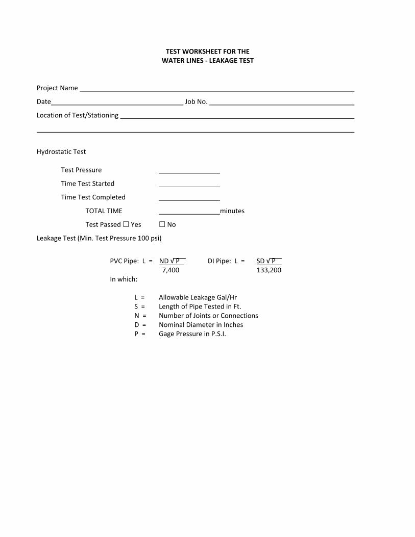
TEST WORKSHEET FOR THE WATER LINES ‐ LEAKAGE TEST
Project Name
Date Job No.
Location of Test/Stationing
Hydrostatic Test Test Pressure
Time Test Started
Time Test Completed
TOTAL TIME minutes
Test Passed Yes No
Leakage Test (Min. Test Pressure 100 psi)
PVC Pipe: L = ND √ P DI Pipe: L = SD √ P 7,400 133,200 In which: L = Allowable Leakage Gal/Hr S = Length of Pipe Tested in Ft. N = Number of Joints or Connections D = Nominal Diameter in Inches P = Gage Pressure in P.S.I.
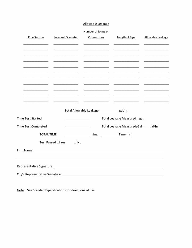
Allowable Leakage
Pipe Section
Nominal Diameter
Number of Joints or
Connections Length of Pipe Allowable Leakage
________________ ________________ ________________ ________________ ________________
________________ ________________ ________________ ________________ ________________
________________ ________________ ________________ ________________ ________________
________________ ________________ ________________ ________________ ________________
________________ ________________ ________________ ________________ ________________
________________ ________________ ________________ ________________ ________________
________________ ________________ ________________ ________________ ________________
________________ ________________ ________________ ________________ ________________
________________ ________________ ________________ ________________ ________________
________________ ________________ ________________ ________________ ________________
________________ ________________ ________________ ________________ ________________
Total Allowable Leakage ___________ gal/hr
Time Test Started Total Leakage Measured gal.
Time Test Completed Total Leakage Measured/Gal=___ gal/hr
TOTAL TIME mins. Time (hr.)
Test Passed Yes No
Firm Name:
Representative Signature
City’s Representative Signature
Note: See Standard Specifications for directions of use.
SECTION 3 SANITARY SEWER LINES
TABLE OF CONTENTS
SECTION 3
SANITARY SEWER LINES
04/2012 i Table of Contents S:\DOCS\CONNELL\W68‐208 WTR SWR ST STNDS\STANDARDS\APRIL 2012\SANITARY SEWER LINES.docx Anderson Perry & Associates, Inc.
PART 1 ‐ General ..................................................................................................................................................... 3‐1 1.1 Scope ...................................................................................................................................................... 3‐1 1.2 Specifications References ....................................................................................................................... 3‐1 1.3 Submittals ............................................................................................................................................... 3‐1 1.4 Care and Handling of Materials .............................................................................................................. 3‐1 1.5 Certification by Manufacturer ................................................................................................................ 3‐2 1.6 Restoration, Finishing, and Cleanup ....................................................................................................... 3‐2
PART 2 ‐ Materials .................................................................................................................................................. 3‐2 2.1 Pipe ......................................................................................................................................................... 3‐2 2.2 Fittings .................................................................................................................................................... 3‐4 2.3 Valves and Appurtenances ..................................................................................................................... 3‐5 2.4 Thrust and Anchor Blocks ....................................................................................................................... 3‐6 2.5 Manholes ................................................................................................................................................ 3‐6 2.6 Pressure Sewer Discharge Manholes ..................................................................................................... 3‐8 2.7 Cleanouts ................................................................................................................................................ 3‐8 2.8 Locating Wire .......................................................................................................................................... 3‐9
PART 3 ‐ Execution .................................................................................................................................................. 3‐9 3.1 Gravity Sewer Construction .................................................................................................................... 3‐9 3.2 Gravity Service Lines ............................................................................................................................. 3‐11 3.3 Gravity Sewer Testing ........................................................................................................................... 3‐11 3.4 Pressure Sewer Construction ............................................................................................................... 3‐14 3.5 Manhole Construction .......................................................................................................................... 3‐15 3.6 Cleanout Construction .......................................................................................................................... 3‐17 3.7 Water‐Sewer Crossing .......................................................................................................................... 3‐18 3.8 Locating Wire ........................................................................................................................................ 3‐18 3.9 Marker Posts ......................................................................................................................................... 3‐19 3.10 Cleaning and Flushing of Completed and Tested Sewers ..................................................................... 3‐19 3.11 Sewer Line Cleaning and Inspection ..................................................................................................... 3‐19 3.12 Work with Existing Asbestos Cement (A/C) Pipe .................................................................................. 3‐20
STANDARD SPECIFICATIONS
SECTION 3
SANITARY SEWER LINES
04/2012 3‐1 Sanitary Sewer Lines S:\DOCS\CONNELL\W68‐208 WTR SWR ST STNDS\STANDARDS\APRIL 2012\SANITARY SEWER LINES.docx Anderson Perry & Associates, Inc.
PART 1 ‐ GENERAL
1.1 Scope
A. These Standard Specifications cover the furnishing and installation of gravity sewer lines, pressure sewer lines, service lines, manholes, cleanouts, and miscellaneous appurtenances. The work includes, unless otherwise specified, furnishing all labor, materials, tools, equipment, and incidentals required to construct a complete sewer system ready for service as outlined in the General Requirements and the City of Connell Standard Plans. Requirements for excavation and backfill of trenches, surface restoration, and special appurtenances are specified under separate sections of these Standard Specifications.
B. Items included in this Standard Specification are intended to be broad in scope and may not always apply to all items of work to be constructed.
1.2 Specifications References
Specification references made herein for manufactured materials such as pipe, fittings, and manhole rings and covers refer to designations for the American Public Works Association (APWA), the American Water Works Association (AWWA), or the American Society for Testing and Materials (ASTM).
1.3 Submittals
Catalog information on all materials and/or equipment to be installed shall be submitted to the City for approval, as required in Section E, Materials Submittals, of the General Requirements, prior to incorporation into the work.
1.4 Care and Handling of Materials
A. Adequate precautions shall be taken to prevent damage to pipes, fittings, manhole components, and all other materials used in construction of a sewerage system. Pipe and other materials during transport shall be secure individually by use of wood spacer blocks or wood crates, or otherwise protected to prevent collision of individual pieces and the possible subsequent damage.
B. All pipe, fittings, manhole components, and valves shall be loaded and unloaded in a manner prevent shock or damage. Under no circumstances shall such material be dropped. All materials on the ground shall be protected from damage. All pipes, fittings, manhole components, valves, and all other materials used in the construction of the sewerage system shall be carefully inspected by the Contractor prior to installation. All defective materials shall be rejected. All materials which are delivered considerably in advance of their installation shall be stored in a satisfactory manner.
STANDARD SPECIFICATIONS
SECTION 3
SANITARY SEWER LINES
04/2012 3‐2 Sanitary Sewer Lines S:\DOCS\CONNELL\W68‐208 WTR SWR ST STNDS\STANDARDS\APRIL 2012\SANITARY SEWER LINES.docx Anderson Perry & Associates, Inc.
C. Proper materials, tools and equipment shall be used by the Contractor for safe and convenient prosecution of the work. All pipes, fittings, etc., shall be carefully lowered into the trench piece by piece in such a manner to prevent any damage to the materials. Under no circumstances shall sewage system materials be dropped or dumped into the trenches.
1.5 Certification by Manufacturer
The Contractor shall furnish to the City a sworn statement from the manufacturer, stating that inspection and all specified tests have been made on the supplied material and that the results thereof comply with appropriate specifications. The statement shall also state that all materials furnished are in accordance with these Standard Specifications and that all materials are new.
1.6 Restoration, Finishing, and Cleanup
The Contractor shall restore or replace all paved surfaces, graveled surfaces, curbing, sidewalks, trees and shrubbery, lawns, pastures, fences and other existing facilities to their original condition. See Standard Specifications – "Excavation and Backfill of Trenches" and Standard Specifications – "Surface Restoration" for specific requirements.
PART 2 ‐ MATERIALS
2.1 Pipe
A. General
Where no specific type of pipe is called for, the Contractor may select any type listed herein. Once a particular type of pipe is selected, the Contractor shall use that type for all pipe of the same diameter. Where a specific type of pipe is specified, the Contractor shall conform to those requirements. Such pipe shall also conform to the appropriate pipe specifications.
B. PVC Gravity Pipe
PVC gravity sewer pipe and fittings 15‐inch diameter and smaller shall conform to ASTM D3034, SDR 35. Pipes 18‐inch diameter to 24‐inch diameter shall conform to ASTM F679. The joints shall be flexible joint with rubber ring gasket.
C. PVC Pressure Pipe
1. PVC pipe for pressure sewer lines shall conform to AWWA C900, DR 18 (150 psi pipe), or as otherwise specified. The pipe shall have flexible rubber gasketed joints conforming to ASTM D3139.
2. Class 160 PVC Pipe for pressure sewer lines shall conform to ASTM D2241, SDR 26. The pipe shall have flexible rubber gasketed joints conforming to ASTM D3139 except where solvent weld joints are specifically called for.

STANDARD SPECIFICATIONS
SECTION 3
SANITARY SEWER LINES
04/2012 3‐3 Sanitary Sewer Lines S:\DOCS\CONNELL\W68‐208 WTR SWR ST STNDS\STANDARDS\APRIL 2012\SANITARY SEWER LINES.docx Anderson Perry & Associates, Inc.
D. Ductile Iron Pipe
1. Ductile iron pipe and fittings shall conform to AWWA C150, AWWA C115, AWWA C151, AWWA C153, and AWWA C110 and shall be minimum pressure Class 350 unless specified otherwise. All ductile iron pipe shall have a bituminous sealed cement mortar lining conforming to AWWA C104. All joints, unless otherwise specified, shall be push‐on rubber gasket joints conforming to AWWA C111.
2. When flanged pipe is required, the Contractor shall provide the D.I. pipe class required by the flange manufacturer to ensure the pipe and flange units are compatible. This data shall be provided to the City for his review prior to ordering these materials. Flanges for couplings and fittings shall conform to ANSI 16.1, 125‐pound bolt hole template.
3. All ductile iron pipe installed shall be encased in 8‐mil‐thick polyethylene encasement installed in accordance with ANSI/AWWA C105/A21.5, ASTM A674, and guidelines set up by the Ductile Iron Pipe Research Association (DIPRA).
E. Polyethylene Lined Ductile Iron Pipe
1. Ductile iron pipe and fittings shall conform to AWWA C150, AWWA C115, AWWA C151, and AWWA C110 and shall be minimum pressure Class 250 unless specified otherwise. The internal pipe lining shall be polyethylene modified to achieve chemical bonding to the metal and shall have a nominal thickness of 40 mils. The lining material shall contain no inert filler except 3 percent carbon black. The pipe bell interior surface through the entire gasket seat, spigot end, and external surface of the spigot to a point beyond gasket engagement shall be coated with the same polyethylene material with a minimum thickness of 10 mils. The lining of the pipe barrel must pass a 7500V holiday test using a dry electrode, and the bell interior and spigot shall pass a 67.5 wet sponge holiday detection test.
2. All joints, unless otherwise specified, shall be push‐on rubber gasket joints conforming to AWWA C111.
3. Mechanical joints shall conform to AWWA C111.
4. When flanged pipe is required, the Contractor shall provide the D.I. pipe class required by the flange manufacturer to ensure the pipe and flange units are compatible. This data shall be provided to the City for review prior to ordering these materials.
STANDARD SPECIFICATIONS
SECTION 3
SANITARY SEWER LINES
04/2012 3‐4 Sanitary Sewer Lines S:\DOCS\CONNELL\W68‐208 WTR SWR ST STNDS\STANDARDS\APRIL 2012\SANITARY SEWER LINES.docx Anderson Perry & Associates, Inc.
F. High Density Polyethylene Pipe
1. High density polyethylene pipe shall conform to AWWA C906. All joints shall be by the heat fusion method in accordance with the manufacturer's requirements.
2. Fittings shall be standard commercial products manufactured by injection molding or by extrusion and machining or fabricated from AWWA C906 pipe.
3. The Contractor shall provide detailed shop drawings for all joints and connections, including provisions for expansion and contraction as recommended by the pipe manufacturer.
2.2 Fittings
A. Fittings for Iron and PVC Pipe
Unless specified otherwise, all fittings such as elbows, tees, crosses, etc., shall be mechanical joint short‐bodied compact ductile iron fittings conforming to AWWA C153, Class 350. When called for, flanged cast iron fittings shall conform to AWWA C110 with ANSI B16.1, 125‐pound bolt hole template. All fittings shall be cement mortar lined in accordance with AWWA C104. Gaskets shall be either ring or full faced, 1/8 inch thick conforming to AWWA C111, Appendix B.
B. Fittings for Sewer Service Connection
Main line fittings for sewer service connections when installing new gravity sewer pipe shall be a gasketed tee suitable for ASTM D3034 or ASTM F679 sewer pipe. When service connections are required on existing sewer lines, a sewer tapping saddle shall be used, such as “Geneco Sealtite,” of the type and model required to match the sewer main line and service line pipe materials, or approved equal.
C. Couplings
Couplings shall have stainless steel shear rings of the size and style required to match the pipe size and type being utilized. Couplings shall be manufactured by Fernco with stainless steel shear rings or approved equal.
D. Restrained Pipe Joints and Fittings
Restrained pipe joints shall be mechanical joint ductile iron with “MEGALUG” field‐installed restraint devices as manufactured by Ebaa Iron, Inc., or approved equal.
STANDARD SPECIFICATIONS
SECTION 3
SANITARY SEWER LINES
04/2012 3‐5 Sanitary Sewer Lines S:\DOCS\CONNELL\W68‐208 WTR SWR ST STNDS\STANDARDS\APRIL 2012\SANITARY SEWER LINES.docx Anderson Perry & Associates, Inc.
2.3 Valves and Appurtenances
A. Gate Valves
1. Gate valves 2 inches and larger shall conform to AWWA C509. Valves shall be designed for 200 psi minimum working pressure and shall be of iron body, resilient seat, non‐rising stem construction. Valves shall be equipped with O‐ring type packing. The valve shall have a 2‐inch AWWA operating nut for buried service or as specified otherwise.
2. The valve ends shall be of the type required to match the pipe to which they will be connected.
3. Valves shall be resilient seated Kennedy KSRW or KSFW, M&H Style 4067 or 7000, or Clow, or equal.
B. Valve Boxes
Each valve shall be equipped with an adjustable cast iron box of the sliding type with a base large enough to cover the top casting of the valve. The diameter of the valve box shall be not less than five (5) inches, and shall be of such length so as to provide the depth of cover over the pipe without full extension. Materials and installation workmanship for valve boxes shall be in accordance with AWWA C600, Section 10.3.
C. Sewage Air Release Valve
1. Air release valves where called for shall be Valve and Primer Corporation, #400 APCO Sewage Air Release Valve and/or #401 APCO Sewage Air and Vacuum Valve with 2‐inch inlet or approved equal. An auxiliary 2‐inch 125 psi bronze rising stem solid disc gate valve shall be installed with all sewage air release valves.
2. Air release valves shall also be furnished with accessory valves and connections (for flushing purposes).
3. The furnishing and installation of sewage air release valves shall include the construction of all associated structures and appurtenances.
D. Plug Valves
1. All plug valves shall conform to AWWA C504. The valve body shall be constructed of cast iron (semi‐steel) conforming to ASTM A126 Class B and shall be protected with a factory‐applied fusion‐bonded coating meeting AWWA C550. The shaft and plug shall be integrally constructed of cast iron (semi‐steel) and shall be 100 percent encapsulated with Buna N rubber. The stem seals shall be Buna N multiple "V" ring stem packing seals. The valve seat surface shall be raised welded‐in overlay of not less than 90 percent nickel.
STANDARD SPECIFICATIONS
SECTION 3
SANITARY SEWER LINES
04/2012 3‐6 Sanitary Sewer Lines S:\DOCS\CONNELL\W68‐208 WTR SWR ST STNDS\STANDARDS\APRIL 2012\SANITARY SEWER LINES.docx Anderson Perry & Associates, Inc.
2. Flange dimensions, facing, and drilling shall conform to ANSI B16.1, Class 125. Mechanical joints shall meet the requirements of AWWA C111/ANSI A21.11.
3. The valve shall have a 2‐inch AWWA operator nut for buried services and handwheel operator for non‐buried services. Worm gear operators shall be furnished for all 4‐inch or larger valves.
4. Valves shall be M&H 1820 eccentric plug valves, Pratt Ballcentric plug valves, or approved equal.
2.4 Thrust and Anchor Blocks
Thrust and anchor blocks shall be located and sized as shown on the City of Connell Standard Plans, and at all changes in direction, or as required by the City. Concrete used for the blocks shall be Portland Cement concrete with a minimum 28‐day strength of 2,500 psi. All concrete shall be placed so that pipe joints and fittings will be accessible for repair. Concrete shall be placed against undisturbed material. Anchor rods shall be 3/4‐inch diameter galvanized steel, embedded a minimum of 18 inches in concrete.
2.5 Manholes
A. Cast‐in‐place Concrete Base Sections
1. Cast‐in‐place concrete base sections for manhole construction shall have a minimum 28‐day strength of 3,000 psi, unless approved otherwise by the Engineer, and shall have thicknesses shown in the City of Connell Standard Plans.
2. Required "U" shaped channels shall be constructed by the use of properly shaped forms. Intersecting flow channels shall have smooth uniform transitions. All channels shall have smooth troweled finishes. All shelf area shall be uniformly shaped, have a rough float finish and shall slightly slope towards the channel. The shelf shall be above the top of the sewer pipe.
3. The Contractor shall be responsible for the determination of pipe hole orientation and grade. Cast‐in‐place base sections will only be used where called for specifically by the City.
B. Precast Concrete Base Sections
1. Precast concrete base sections shall be approved by the City and shall conform to ASTM C478. Concrete shall be consolidated by mechanical vibration. Reinforcing shall be provided in the base and walls. Minimum concrete thickness shall be as shown in the City of Connell Standard Plans.
2. Required "U" shaped channels shall be constructed by the use of properly shaped forms. Intersecting flow channels shall have smooth uniform transitions. All channels shall have smooth troweled finishes. All shelf area shall be uniformly shaped, have a rough
STANDARD SPECIFICATIONS
SECTION 3
SANITARY SEWER LINES
04/2012 3‐7 Sanitary Sewer Lines S:\DOCS\CONNELL\W68‐208 WTR SWR ST STNDS\STANDARDS\APRIL 2012\SANITARY SEWER LINES.docx Anderson Perry & Associates, Inc.
float finish and shall slightly slope towards the channel. The shelf shall be above the top of the sewer pipe.
3. The Contractor shall be responsible for the determination of pipe hole orientation and grade. Precast base sections shall be used unless specifically called for otherwise by the City.
C. Precast Concrete Manhole Sections
1. Precast concrete manhole sections shall conform to ASTM C478 and consist of circular sections in the standard 48‐inch diameter or larger. No more than two lift holes shall be cast into each section. Holes shall be located as to not damage reinforcing or expose it to corrosion. At the manufacturer's option, steel loops may be provided for handling, in lieu of lift holes. All lift holes shall be patched to prevent water seepage into the manhole, utilizing an approved, non‐shrink grout.
2. Precast manhole cones shall be eccentric unless otherwise allowed by the City and shall meet ASTM C478.
3. Flat slab covers for manholes shall conform to ASTM C478 and shall only be used when specifically allowed by the City. Slabs, cones and ring sections shall be free from fractures, cracks, rock pockets, or exposed reinforcement. Joint seal material shall be “Kent seal” mastic acrylic polymeric sealant, O‐ring rubber gasket, or approved equal.
4. Manholes which have a depth of 5‐1/2 feet or less, from the top of the manhole cover to the pipe invert, shall utilize a 2‐foot tall cone section. Flat slab covers shall not be used for manholes less than 5‐1/2 feet in depth, unless approved by the City.
D. Pipe Connection to Manholes
1. All pipe connections to manholes shall be constructed as shown on the City of Connell Standard Plans, shall be flexible, and shall allow movement of the sewer pipe in all directions. Manhole pipe couplings shall be suitable for the sewer pipe type connecting to the manhole.
2. A/C sewer couplings with an appropriate adaptor gasket by Romac Industries, or approved equal, may be used for cast‐in‐place manhole bases.
3. When precast base sections are used, an A‐Lok pipe connector as manufactured by A‐Lok Products, Inc., PSX Flexible Connector as manufactured by Press Seal Gasket Corporation, Kor‐N‐Seal as manufactured by Core and Seal Company, or approved equal shall be used.
4. Fittings for drop manholes shall be of the same material as the attached sewer pipe.
STANDARD SPECIFICATIONS
SECTION 3
SANITARY SEWER LINES
04/2012 3‐8 Sanitary Sewer Lines S:\DOCS\CONNELL\W68‐208 WTR SWR ST STNDS\STANDARDS\APRIL 2012\SANITARY SEWER LINES.docx Anderson Perry & Associates, Inc.
E. Manhole Rings and Covers
1. Castings shall be tough, close‐grained, gray iron free from blow holes, shrinkage and cold sheets.
2. Manhole rings and covers shall conform to ASTM A48 and shall be smooth, sound, clean and free from blisters and defects. Castings and covers shall be planed and ground when necessary to ensure flat and true surfaces. Covers shall be true and shall seat within the ring at all points.
3. Manhole rings and covers shall be Olympic Foundry Model MH30A single hole cover or approved equal. The word "sewer" shall be printed on the cover.
F. Manhole Stubouts
1. Manhole stubouts shall be constructed as called for on the City of Connell Standard Plans and as directed by the City. The stubouts shall have the appropriate flexible connection at the manhole.
2. The outside end of the stubout shall be secured, sealed watertight with a block and plug with rubber ring seal.
3. All stubouts shall be 8‐inch unless otherwise required by the City.
2.6 Pressure Sewer Discharge Manholes
The Contractor shall construct the "Pressure Sewer Discharge Manholes" as directed by the City and also in accordance with the specifications herein for standard manholes.
2.7 Cleanouts
A. Cast Iron Rings and Covers
Main line cleanouts shall have cast iron rings and covers such as Olympic Foundry M1007.
B. Pipe
Pipe used in the construction of cleanouts shall be consistent with type of sewer pipe to which it is connected.
STANDARD SPECIFICATIONS
SECTION 3
SANITARY SEWER LINES
04/2012 3‐9 Sanitary Sewer Lines S:\DOCS\CONNELL\W68‐208 WTR SWR ST STNDS\STANDARDS\APRIL 2012\SANITARY SEWER LINES.docx Anderson Perry & Associates, Inc.
2.8 Locating Wire
A. Locating wire shall be a minimum of 12 awg UF solid copper with green colored insulation. The use of THHN wire will not be acceptable.
B. At all splices the connecting ends of the wires shall be overlapped and tied. The ends shall be stripped and connected with a wire nut to ensure an electrical connection and made waterproof with an approved silicone splice kit.
C. Where location wire is to be secured to exterior of manhole cleanouts, valve boxes, etc., stainless steel pipe straps shall be used.
D. The splice kit shall be King Technology Model 50‐566 or approved equal.
PART 3 ‐ EXECUTION
3.1 Gravity Sewer Construction
A. Trench Excavation and Backfill
Trench excavation and backfill shall be performed as specified in the Standard Specifications – “Excavation and Backfill of Trenches.”
B. Installation of Pipe
1. Gravity sewer pipe shall be installed in accordance with the best current practices and as required by the manufacturer. Gravity sewer pipe, unless otherwise approved by the City, shall be laid by progressing up grade from the existing or newly constructed sewer; the sewer pipe shall be installed with bell ends laid upgrade unless otherwise approved. Each pipe shall be properly bedded so as to be supported along the full length of the pipe. A suitable foundation shall be achieved by a slight excavation for the bell at each joint.
2. All rubber ring joints shall be lubricated, except when using rolling rubber gaskets with concrete pipe, and installed in accordance with the installation instructions of the pipe manufacturer, taking particular care to avoid pinching or otherwise causing damage to the rubber ring. All joints shall be free of dirt and other foreign matter prior to the joining of the next pipe. All pipe shall be installed to prevent creep and misalignment of joints. All pipe shall have a ring painted around the spigot ends in such a manner as to allow field checking of setting depth of pipe in socket.
3. Gravity sewer pipe shall be installed with the use of a laser beam and target. Unless the work involves deep excavations, traffic problems, water problems, or approved by the City, the trench for the first 100 feet shall not be backfilled until the sewer grade has been checked. The Contractor shall set and aim the laser as controlled by the “cuts” and “slopes.” Careful attention shall be given to the setting up of the laser and the periodic
STANDARD SPECIFICATIONS
SECTION 3
SANITARY SEWER LINES
04/2012 3‐10 Sanitary Sewer Lines S:\DOCS\CONNELL\W68‐208 WTR SWR ST STNDS\STANDARDS\APRIL 2012\SANITARY SEWER LINES.docx Anderson Perry & Associates, Inc.
checking of its aim, etc. All grade checking of laser shall be the responsibility of the Contractor. All pipe shall be installed true to line and grade. A tolerance of plus or minus 1/4‐inch deviation from true grade at each joint will be allowed. Extra care shall be given to the installation of sewer lines at minimum slopes to avoid flat slopes in the line. All pipe shall be installed true to line. Except when approved or specified, the Contractor may not install a pipeline on a curve.
a. For rubber gasketed ductile iron pipe installed on a curve, the pipe shall be joined in a straight alignment, then deflected. The amount of deflection shall not exceed 80 percent of the recommended maximum deflection specified in AWWA C600.
b. For PVC pipe installed on a curve, deflection of the pipe shall be achieved by bending the pipe within the limitations specified by the pipe manufacturer. Joint deflection of PVC pipe is not allowed.
4. All foreign matter and gravel shall be removed from the inside of the pipe and fittings before being installed and the pipe and fittings shall be kept clean during placement. No pipe shall be laid in water or when conditions exist that in the opinion of the City are unsuitable for the placing of pipe. All pipe and manholes shall be covered or plugged at night and whenever the work is not supervised.
5. The Contractor may elect, at his own option, to drain or pump groundwater from the trenches into previously placed new sewer lines as long as adequate disposal is provided. The Contractor shall not discharge any groundwater into existing live sewer lines. Adequate provisions shall be made by the Contractor for final disposal of the groundwater from trenches as approved by the City. Any water discharged into new sewer lines shall be properly screened to prevent the entrance of debris and gravel. At the termination of dewatering operations the Contractor shall thoroughly clean the sewer lines that were used. No sewer lines will be accepted as completed until being cleaned as approved by the City.
6. All pipe/manhole connections shall be watertight. The manhole pipe couplings shall be installed in accordance with all manufacturer instructions. All connections shall match the grade and alignment of the pipe entering and exiting each manhole. Manhole pipe connections shall be constructed so that the wastewater flow through the manhole is not restricted in any way.

STANDARD SPECIFICATIONS
SECTION 3
SANITARY SEWER LINES
04/2012 3‐11 Sanitary Sewer Lines S:\DOCS\CONNELL\W68‐208 WTR SWR ST STNDS\STANDARDS\APRIL 2012\SANITARY SEWER LINES.docx Anderson Perry & Associates, Inc.
3.2 Gravity Service Lines
A. Gravity service lines shall be constructed in accordance with the City of Connell Standard Plans, Standard Specifications, and applicable provisions of the International Plumbing Code (IPC) as amended by the State. The minimum slope of service lines shall be 1/4‐inch per foot unless otherwise approved by the City. The pipe size of gravity service lines shall be a minimum 4‐inch diameter unless otherwise approved. Dead ends of service lines shall be marked with steel fence posts installed in the ground as shown on the City of Connell Standard Plans.
B. Connection of service lines to new or existing gravity sewer main lines shall be as per the City of Connell Standard Plans and shall be inspected and accepted by the City prior to backfilling. All sewer service connections shall be watertight utilizing appropriate sewer service saddles or wyes. An approved tee fitting shall be used when new sewer mains are being installed. All holes and taps into an existing sewer main shall be cut using an approved tapping machine.
C. In the construction of new sewage collection systems, connection of new services allowing sewage into the system shall not be made until approval for connections has been given by the City. No existing sewer service shall be interrupted without the approval of the City and service owner. Connections of new service lines to existing service lines shall be by the proper adaptor coupling.
D. The Contractor shall obtain all necessary permits required to construct service lines on private property. The Contractor must utilize a licensed plumber for service line work on private property when required by state or local regulations.
3.3 Gravity Sewer Testing
A. General
The Contractor shall furnish all labor, necessary equipment, and other apparatus including, but not limited to, gauges, mechanical or pneumatic plugs, and air hoses, necessary to properly perform the testing of sewer lines as specified. The Contractor may low pressure test sections of sewer lines before backfilling at his own option; but the acceptance test shall be performed only after backfilling, cleaning, and flushing has been completed.
B. Acceptance Test
The Contractor shall perform all preliminary testing required to determine that the lines to be tested are acceptable and comply with the requirements of this section of the specifications. After the Contractor has determined that the lines will pass the required test, the Contractor shall arrange for an acceptance test to be witnessed by the City's representative. The Contractor shall coordinate the timing of this acceptance test with the City's representative. The lines will not be accepted until the acceptance test has been witnessed and documented as passing.
STANDARD SPECIFICATIONS
SECTION 3
SANITARY SEWER LINES
04/2012 3‐12 Sanitary Sewer Lines S:\DOCS\CONNELL\W68‐208 WTR SWR ST STNDS\STANDARDS\APRIL 2012\SANITARY SEWER LINES.docx Anderson Perry & Associates, Inc.
C. Test Procedure
The method of testing follows the procedures outlined in "Recommended Practice for Low‐Pressure Air Testing of Installed Sewer Pipe" published by Uni‐Bell PVC Pipe Association, May 1990. Specific questions concerning test procedures may be referred to this publication. To facilitate test verification by the City, all air used shall pass through a single, above‐ground control panel. The City shall have the option of requiring the use of a City gauge. Test procedures are summarized below:
1. Field Test
a. The Contractor may wet the lines prior to testing.
b. Determine the average height of the groundwater over the line. The test pressures required shall be increased 0.433 psi for each foot of average water depth over the exterior crown of the pipe.
c. Add air slowly to the section of system being tested until the internal air pressure is raised to 4.0 psig greater than the average back pressure due to groundwater, but no greater than 9.0 psig.
d. After the test pressure is reached, allow at least two minutes for the air temperature to stabilize adding only the amount of air required to maintain pressure.
e. After the temperature stabilization period, disconnect the air supply.
f. Record the time in seconds that is required for the internal air pressure to drop 0.5 psig from 3.5 psig to 3.0 psig greater than the average back pressure due to groundwater.
g. If the time shown in Table I (attached at the end of this Standard Specification), for the designated pipe size and length, elapses before the air pressure drops 0.5 psig, the section undergoing test shall have passed. The test may be discontinued once the prescribed time has elapsed even though the 0.5 psig drop has not occurred.
h. If the pressure drops 0.5 psig before the appropriate time shown in Table I has elapsed, the air loss rate shall be considered excessive and the section of pipe has failed the test.
i. A Q value of 0.0015 cubic feet per minute per square foot shall be utilized to assure the City of quality pipe materials, good workmanship and tight joints.
2. Use the Test Work Sheet at the end of this Standard Specification for reporting test results for each section of sewer line tested.
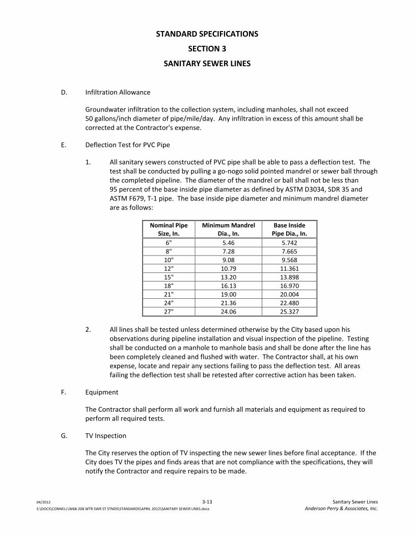
STANDARD SPECIFICATIONS
SECTION 3
SANITARY SEWER LINES
04/2012 3‐13 Sanitary Sewer Lines S:\DOCS\CONNELL\W68‐208 WTR SWR ST STNDS\STANDARDS\APRIL 2012\SANITARY SEWER LINES.docx Anderson Perry & Associates, Inc.
D. Infiltration Allowance
Groundwater infiltration to the collection system, including manholes, shall not exceed 50 gallons/inch diameter of pipe/mile/day. Any infiltration in excess of this amount shall be corrected at the Contractor's expense.
E. Deflection Test for PVC Pipe
1. All sanitary sewers constructed of PVC pipe shall be able to pass a deflection test. The test shall be conducted by pulling a go‐nogo solid pointed mandrel or sewer ball through the completed pipeline. The diameter of the mandrel or ball shall not be less than 95 percent of the base inside pipe diameter as defined by ASTM D3034, SDR 35 and ASTM F679, T‐1 pipe. The base inside pipe diameter and minimum mandrel diameter are as follows:
Nominal PipeSize, In.
Minimum MandrelDia., In.
Base Inside Pipe Dia., In.
6" 5.46 5.742
8" 7.28 7.665
10" 9.08 9.568
12" 10.79 11.361
15" 13.20 13.898
18" 16.13 16.970
21" 19.00 20.004
24" 21.36 22.480
27" 24.06 25.327
2. All lines shall be tested unless determined otherwise by the City based upon his observations during pipeline installation and visual inspection of the pipeline. Testing shall be conducted on a manhole to manhole basis and shall be done after the line has been completely cleaned and flushed with water. The Contractor shall, at his own expense, locate and repair any sections failing to pass the deflection test. All areas failing the deflection test shall be retested after corrective action has been taken.
F. Equipment
The Contractor shall perform all work and furnish all materials and equipment as required to perform all required tests.
G. TV Inspection
The City reserves the option of TV inspecting the new sewer lines before final acceptance. If the City does TV the pipes and finds areas that are not compliance with the specifications, they will notify the Contractor and require repairs to be made.
STANDARD SPECIFICATIONS
SECTION 3
SANITARY SEWER LINES
04/2012 3‐14 Sanitary Sewer Lines S:\DOCS\CONNELL\W68‐208 WTR SWR ST STNDS\STANDARDS\APRIL 2012\SANITARY SEWER LINES.docx Anderson Perry & Associates, Inc.
3.4 Pressure Sewer Construction
A. Pipeline
1. Pipe shall meet the material specifications contained herein. All work performed in the installation of pressure sewer lines shall be performed as per the applicable portions of subsection "Gravity Sewers‐Construction" contained herein, and as required by the manufacturer. When it is necessary to deflect pipe joints to conform to the profile and alignment of the sewage forcemain, the amount of deflection per joint shall not exceed 70 percent of the deflection recommended by the manufacturer.
2. Installation of service line pipe shall be in accordance with the applicable requirements contained herein. Dead ends of service lines shall be marked with steel fence posts installed in the ground as shown on the City of Connell Standard Plans.
3. In the construction of new sewage collection systems, connection of new services allowing sewage into the system shall not be made until approval for connections has been given by the City. No existing sewer service shall be interrupted without the approval of the City and service owner.
4. The Contractor shall obtain all necessary permits required to construct service lines on private property.
B. Testing
1. General
The Contractor shall be responsible for determining the length of any given section of line to be tested. It is recommended that the length of line to be tested not be excessive so that the identification of any problem areas can be readily made. It is also recommended that testing follow closely after the pipe installation and backfill.
2. Hydrostatic Testing of Pressure Sewer Lines
a. Each section of the lines before being placed into service shall be isolated and slowly filled with water. Air should be expelled from the lines through taps made at the high points. The Contractor shall be responsible for making any necessary taps.
b. All lines shall be pressure tested by the Contractor at 100 psi pressure for one hour. Any cracked or defective pipe or fitting shall be removed and replaced.
STANDARD SPECIFICATIONS
SECTION 3
SANITARY SEWER LINES
04/2012 3‐15 Sanitary Sewer Lines S:\DOCS\CONNELL\W68‐208 WTR SWR ST STNDS\STANDARDS\APRIL 2012\SANITARY SEWER LINES.docx Anderson Perry & Associates, Inc.
3. Leakage Test
a. Each section of the line before being placed into service shall be tested by the Contractor for leakage for a period of two hours at an average gage pressure of 60 psi. The pressure during the test shall not fall below 40 psi. The allowable leakage is defined by the following equation:
L=ND (P)0.5/7400
in which:
L = allowable leakage (gal/hr) N = number of joints or connections D = nominal diameter in inches P = average gage pressure during the test in psi.
b. Leakage is defined as the quantity of water supplied into the section of line being tested, during and at the end of the test, that quantity being such that the pressure at the end of the test is equal to the pressure at the beginning of the test.
c. Should any test disclose leakage greater than that specified, the Contractor shall locate and repair the defective joints until the leakage is within the specified allowance.
4. Equipment
The Contractor shall perform and provide all equipment and materials necessary to perform the required test.
3.5 Manhole Construction
A. Installation
1. Manholes shall be constructed to the line, grade and detail as approved by the City. Excavation and backfill of the manhole shall be performed in the same manner as specified in Standard Specifications ‐ “Excavation and Backfill of Trenches,” where applicable. Backfill shall be brought up evenly on all sides of the manhole.
2. The manhole base section shall be carefully placed on a prepared base of 6‐inch minimum deep crushed rock so as to be fully and uniformly supported in true alignment, and making sure that all entering pipes can be inserted on proper grade.
3. All connections and joints made at manholes shall be watertight. All manholes are to be watertight and any leakage shall be corrected in an approved manner.
STANDARD SPECIFICATIONS
SECTION 3
SANITARY SEWER LINES
04/2012 3‐16 Sanitary Sewer Lines S:\DOCS\CONNELL\W68‐208 WTR SWR ST STNDS\STANDARDS\APRIL 2012\SANITARY SEWER LINES.docx Anderson Perry & Associates, Inc.
B. Testing
1. The Contractor shall be responsible for providing all equipment, labor, and materials necessary for performing manhole testing.
2. All manholes shall be individually tested to verify their watertightness. Each manhole shall be tested for acceptance after all work has been completed including restoration work. Preliminary testing prior to final acceptance is advised.
3. The testing shall be by a vacuum test in conformance with ASTM C1244 “Standard Test Method for Concrete Sewer Manholes by the Negative Air Pressure (Vacuum) Test.” All manholes must be watertight. Any points of leakage must be repaired by the Contractor, even if the manhole passed the vacuum test.
4. The vacuum test shall generally follow the following procedures:
a. All pipes entering the manhole shall be temporarily plugged, taking care to securely brace the pipes and plugs to prevent them from being drawn into the manhole.
b. The test head shall be placed at the top of the manhole in accordance with the manufacturer’s recommendations.
c. A vacuum of 10 inches of mercury shall be drawn on the manhole, the valve on the vacuum line of the test head closed, and the vacuum pump shut off. The time shall be measured for the vacuum to drop to 9 inches of mercury.
d. The manhole shall pass if the time for the vacuum reading to drop from 10 inches of mercury to 9 inches of mercury meets or exceeds the values indicated in Table 1.
e. If the manhole fails the initial test, necessary repairs shall be made by an approved method. The manhole shall then be retested until a satisfactory test is obtained.
f. The results of the manhole test shall be reported on the “Attachment B ‐ Manhole Test Record” form, a copy of which is located at the end of this section. The Contractor shall complete this form and provide it to the City prior to completion.
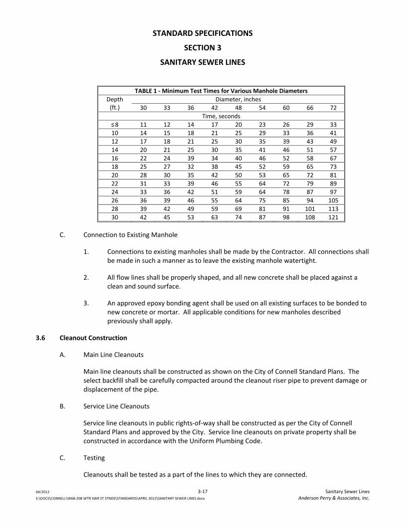
STANDARD SPECIFICATIONS
SECTION 3
SANITARY SEWER LINES
04/2012 3‐17 Sanitary Sewer Lines S:\DOCS\CONNELL\W68‐208 WTR SWR ST STNDS\STANDARDS\APRIL 2012\SANITARY SEWER LINES.docx Anderson Perry & Associates, Inc.
TABLE 1 ‐ Minimum Test Times for Various Manhole Diameters
Depth (ft.)
Diameter, inches
30 33 36 42 48 54 60 66 72
Time, seconds
≤ 8 11 12 14 17 20 23 26 29 33
10 14 15 18 21 25 29 33 36 41
12 17 18 21 25 30 35 39 43 49
14 20 21 25 30 35 41 46 51 57
16 22 24 39 34 40 46 52 58 67
18 25 27 32 38 45 52 59 65 73
20 28 30 35 42 50 53 65 72 81
22 31 33 39 46 55 64 72 79 89
24 33 36 42 51 59 64 78 87 97
26 36 39 46 55 64 75 85 94 105
28 39 42 49 59 69 81 91 101 113
30 42 45 53 63 74 87 98 108 121
C. Connection to Existing Manhole
1. Connections to existing manholes shall be made by the Contractor. All connections shall be made in such a manner as to leave the existing manhole watertight.
2. All flow lines shall be properly shaped, and all new concrete shall be placed against a clean and sound surface.
3. An approved epoxy bonding agent shall be used on all existing surfaces to be bonded to new concrete or mortar. All applicable conditions for new manholes described previously shall apply.
3.6 Cleanout Construction
A. Main Line Cleanouts
Main line cleanouts shall be constructed as shown on the City of Connell Standard Plans. The select backfill shall be carefully compacted around the cleanout riser pipe to prevent damage or displacement of the pipe.
B. Service Line Cleanouts
Service line cleanouts in public rights‐of‐way shall be constructed as per the City of Connell Standard Plans and approved by the City. Service line cleanouts on private property shall be constructed in accordance with the Uniform Plumbing Code.
C. Testing
Cleanouts shall be tested as a part of the lines to which they are connected.
STANDARD SPECIFICATIONS
SECTION 3
SANITARY SEWER LINES
04/2012 3‐18 Sanitary Sewer Lines S:\DOCS\CONNELL\W68‐208 WTR SWR ST STNDS\STANDARDS\APRIL 2012\SANITARY SEWER LINES.docx Anderson Perry & Associates, Inc.
3.7 Water‐Sewer Crossing
A. Wherever possible, the bottom of new or existing water lines shall be 1.5 feet or more above the top of the sanitary sewer line. The minimum requirements for water‐sewer separation set by the Washington State Department of Ecology’s criteria for sewage works design shall be met at all times. Where the water line crosses over the sanitary sewer line but with a clearance of less than 1.5 feet, the Contractor shall center one full length of the new sewer pipe at the crossing point. Use PVC pressure pipe, ASTM D2241, SDR 32.5, (125 psi) at the crossing point. Where the water line crosses under the sanitary sewer line, the Contractor shall center one full length of the new sewer pipe at the crossing point.
B. If the City determines that conditions are not favorable or finds evidence of poor water line condition, the existing water line shall be replaced with a full length of water pipe centered at the crossing point.
C. When constructing sewer service lines, the City may require the depth of the service lines to be revised in order to eliminate the need for a water‐sewer line crossing.
3.8 Locating Wire
A. A continuous solid copper tracer or locating wire shall be taped along the top of all pressure sewer lines, including service lines. This wire shall be secured to the top of the pipe at maximum 10‐foot intervals using 6‐inch strips of 2‐inch wide duct tape. All splices shall be tied, electrically continuous, and made waterproof.
B. The location wire shall be brought to the surface at all valve boxes, cleanouts, and terminal line marker fence posts. The wire shall be secured to valve boxes, cleanouts, and posts with stainless steel pipe clamps.
C. Access to terminal ends of the locating wire shall be made at all manholes, cleanouts, valve boxes, terminal line marker fence posts, and as shown on the City of Connell Standard Plans. The result of this installation shall be a continuous wire circuit electrically isolated from ground.
D. The Contractor shall be responsible for testing continuity and for testing isolation from ground in the wire after all work has been completed on the test section. The Contractor is advised to do intermediate testing on his own after backfilling operations and prior to surface restoration work to be sure continuity is maintained. If there is a break or defect in the wire, it shall be the Contractor's responsibility to locate and repair the defect.
STANDARD SPECIFICATIONS
SECTION 3
SANITARY SEWER LINES
04/2012 3‐19 Sanitary Sewer Lines S:\DOCS\CONNELL\W68‐208 WTR SWR ST STNDS\STANDARDS\APRIL 2012\SANITARY SEWER LINES.docx Anderson Perry & Associates, Inc.
E. The continuity of the location wire shall be tested from one test load point to the next by use of a temporary wire laid between test points in‐line with an ohmmeter. Resistance shall be measured with an approved ohmmeter that has been properly calibrated. The continuity of a test section will be accepted if the resistance of the test section does not exceed 5 ohms per 500 feet of location wire being tested. Isolation from ground shall be measured with a megohm meter and shall be a minimum of 20 megohms for any section of location wire tested.
F. The City shall witness the acceptance test.
3.9 Marker Posts
The Contractor shall furnish and place 4"x4" pressure treated wood posts at locations shown on the City of Connell Standard Plans and as directed by the City to mark the locations of certain manholes and other appurtenances. Posts shall be set solidly in the ground. All posts improperly set shall be reset.
3.10 Cleaning and Flushing of Completed and Tested Sewers
A. Prior to final inspection of the sewer system by the City, the Contractor shall flush and clean all parts of the system. All accumulated construction debris, rocks, gravel, sand, silt, and other foreign material shall be removed from the sewer system at or near the closest downstream manhole. If necessary, mechanical rodding or bucketing equipment shall be used.
B. All sewer pipes including gravity sewers, pressure sewer lines, service lines, etc., installed shall be flushed, as thoroughly as possible with the water pressure and outlets available. Flushing shall be done after the pressure test has been made. It must be understood that flushing removes only the lighter solids and cannot be relied upon to remove heavy material allowed to get into the sewers during construction. The Contractor shall provide sufficient water and appropriately sized taps at either end of the line to develop a velocity in the sewers during flushing of at least 2.5 fps.
3.11 Sewer Line Cleaning and Inspection
A. Necessary Repairs
If in the opinion of the City, after TV inspection, the sewer lines in question require repair and/or replacement to meet the original contract specifications, the Contractor shall be required to perform all necessary repairs and replacement at no cost to the City. It shall be understood that any necessary repairs required will have been the result of poor construction or defective materials.
B. Inspection of Lines
Supplemental to TV inspection shall be the inspection of lines by excavation at suspected joints, etc. If, in the opinion of the City, a line is suspected to have excess infiltration, the City may require the Contractor to excavate down to the joint(s) in question. The Contractor is responsible only for those lines or parts thereof he actually constructed. If any joints or pipes
STANDARD SPECIFICATIONS
SECTION 3
SANITARY SEWER LINES
04/2012 3‐20 Sanitary Sewer Lines S:\DOCS\CONNELL\W68‐208 WTR SWR ST STNDS\STANDARDS\APRIL 2012\SANITARY SEWER LINES.docx Anderson Perry & Associates, Inc.
are found to be defective in that portion the Contractor constructed, the Contractor alone shall bear the cost of locating, excavation, and replacing or repairing the defective pipe or joints in a line. If no defects are found in a suspect line, the City shall bear the justifiable costs incurred in the search for infiltration defects.
3.12 Work with Existing Asbestos Cement (A/C) Pipe
A. When working with A/C pipe, the Contractor shall take all precautions necessary to reduce airborne asbestos during construction.
B. All work with A/C pipe shall conform with American Water Works Association Publication “Work Practices for Asbestos‐Cement Pipe.” The Contractor shall cut asbestos cement pipe by using snap cutters only. The use of carbide‐tipped cutting blades or high speed, abrasive disks shall not be permitted as a means of cutting A/C pipe. Machining of this pipe shall be done with a manual or power‐driven lathe. Hole cutting shall be accomplished with a tapping machine. Use of shell cutters, rasps, chisels, electric drills, right angle sanders, or other high speed abrasive tools shall not be permitted. Dust and cuttings from all work shall be removed by wet mopping.
C. All waste material shall be collected in a covered container and disposed at a landfill certified by the state or EPA to accept demolition waste.
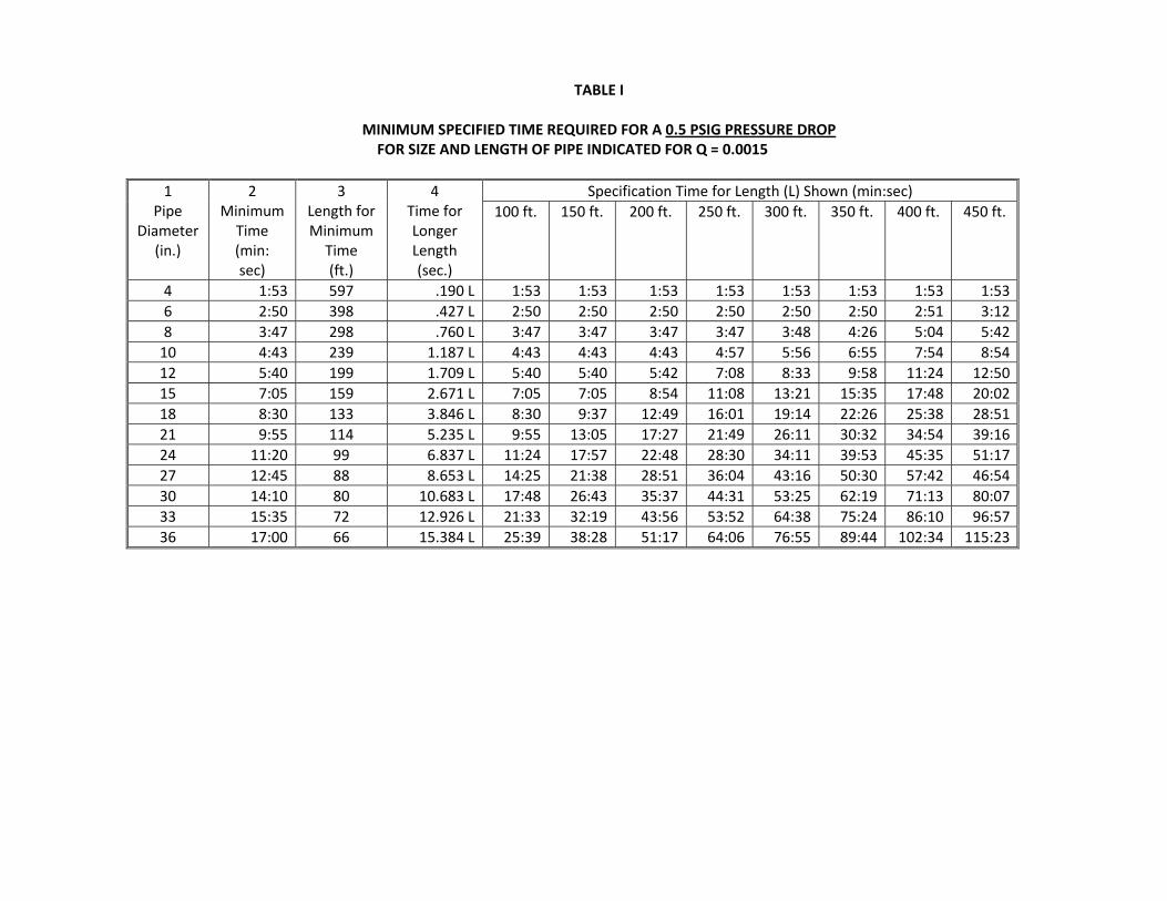
TABLE I
MINIMUM SPECIFIED TIME REQUIRED FOR A 0.5 PSIG PRESSURE DROP FOR SIZE AND LENGTH OF PIPE INDICATED FOR Q = 0.0015
1 Pipe
Diameter (in.)
2 Minimum Time (min: sec)
3 Length for Minimum Time (ft.)
4 Time for Longer Length (sec.)
Specification Time for Length (L) Shown (min:sec)
100 ft. 150 ft. 200 ft. 250 ft. 300 ft. 350 ft. 400 ft. 450 ft.
4 1:53 597 .190 L 1:53 1:53 1:53 1:53 1:53 1:53 1:53 1:53
6 2:50 398 .427 L 2:50 2:50 2:50 2:50 2:50 2:50 2:51 3:12
8 3:47 298 .760 L 3:47 3:47 3:47 3:47 3:48 4:26 5:04 5:42
10 4:43 239 1.187 L 4:43 4:43 4:43 4:57 5:56 6:55 7:54 8:54
12 5:40 199 1.709 L 5:40 5:40 5:42 7:08 8:33 9:58 11:24 12:50
15 7:05 159 2.671 L 7:05 7:05 8:54 11:08 13:21 15:35 17:48 20:02
18 8:30 133 3.846 L 8:30 9:37 12:49 16:01 19:14 22:26 25:38 28:51
21 9:55 114 5.235 L 9:55 13:05 17:27 21:49 26:11 30:32 34:54 39:16
24 11:20 99 6.837 L 11:24 17:57 22:48 28:30 34:11 39:53 45:35 51:17
27 12:45 88 8.653 L 14:25 21:38 28:51 36:04 43:16 50:30 57:42 46:54
30 14:10 80 10.683 L 17:48 26:43 35:37 44:31 53:25 62:19 71:13 80:07
33 15:35 72 12.926 L 21:33 32:19 43:56 53:52 64:38 75:24 86:10 96:57
36 17:00 66 15.384 L 25:39 38:28 51:17 64:06 76:55 89:44 102:34 115:23
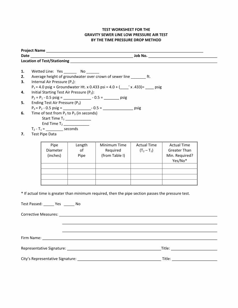
TEST WORKSHEET FOR THE GRAVITY SEWER LINE LOW PRESSURE AIR TEST
BY THE TIME PRESSURE DROP METHOD
Project Name Date Job No. Location of Test/Stationing
1. Wetted Line: Yes ______ No ______ 2. Average height of groundwater over crown of sewer line _______ ft. 3. Internal Air Pressure (P1):
P1 = 4.0 psig + Groundwater Ht. x 0.433 psi = 4.0 + (____' x .433)= ____ psig 4. Initial Starting Test Air Pressure (P2):
P2 = P1 ‐ 0.5 psig = ‐ 0.5 = psig 5. Ending Test Air Pressure (P3)
P3 = P2 ‐ 0.5 psig = ‐ 0.5 = psig 6. Time of test from P2 to P3 (in seconds) Start Time T1 ____________ End Time T2 ____________ T2 ‐ T1 = seconds 7. Test Pipe Data
Pipe Diameter (inches)
Length of Pipe
Minimum Time Required
(from Table I)
Actual Time (T2 – T1)
Actual Time Greater Than Min. Required?
Yes/No*
* If actual time is greater than minimum required, then the pipe section passes the pressure test. Test Passed: Yes No Corrective Measures:
Firm Name:
Representative Signature: Title: City’s Representative Signature: Title:
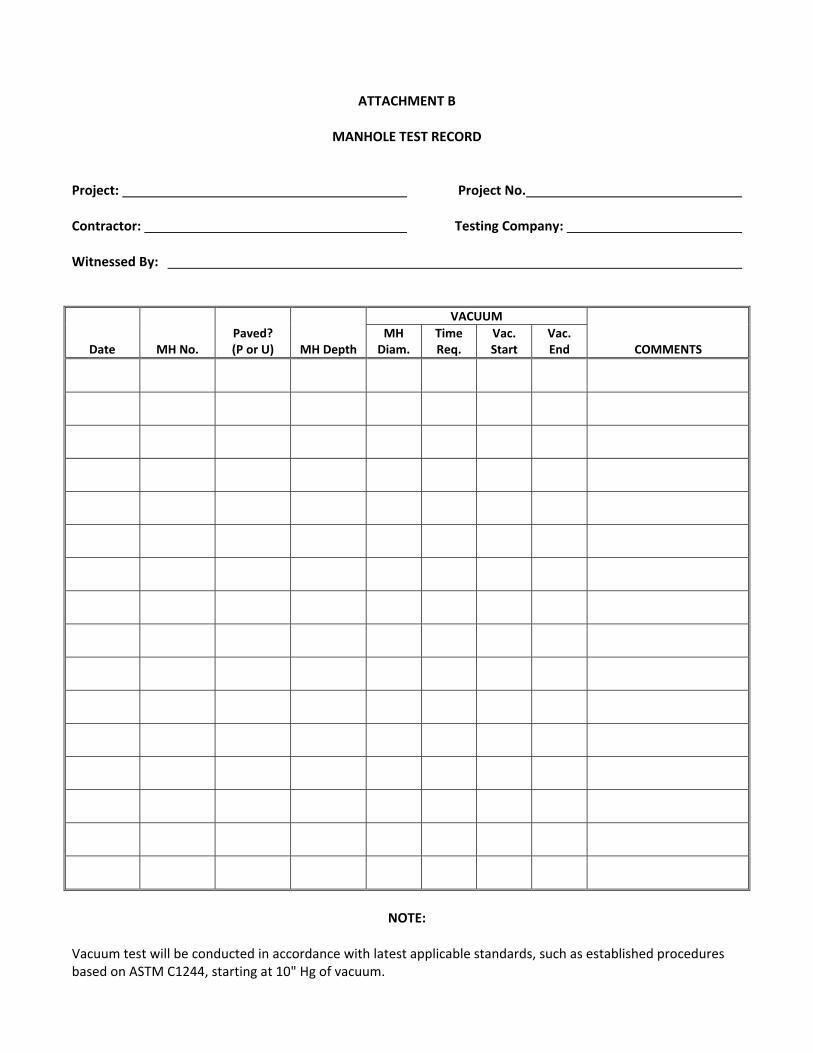
ATTACHMENT B
MANHOLE TEST RECORD
Project: Project No.
Contractor: Testing Company:
Witnessed By:
Date MH No. Paved? (P or U) MH Depth
VACUUM
COMMENTS MH Diam.
Time Req.
Vac. Start
Vac. End
NOTE:
Vacuum test will be conducted in accordance with latest applicable standards, such as established procedures based on ASTM C1244, starting at 10" Hg of vacuum.
SECTION 4 STORM DRAINAGE SYSTEM
TABLE OF CONTENTS
SECTION 4
STORM DRAINAGE SYSTEM
04/2012 i Table of Contents S:\DOCS\CONNELL\W68‐208 WTR SWR ST STNDS\STANDARDS\APRIL 2012\STORM DRAINAGE.docx Anderson Perry & Associates, Inc.
PART 1 ‐ General ..................................................................................................................................................... 4‐1 1.1 Scope ...................................................................................................................................................... 4‐1 1.2 Specification References ........................................................................................................................ 4‐1 1.3 Catalog Information ................................................................................................................................ 4‐1 1.4 Care and Handling of Materials .............................................................................................................. 4‐1 1.5 Submittals ............................................................................................................................................... 4‐2
PART 2 ‐ Materials .................................................................................................................................................. 4‐2 2.1 Gravity Storm Drains .............................................................................................................................. 4‐2 2.2 Manholes ................................................................................................................................................ 4‐3 2.3 Catch Basins ............................................................................................................................................ 4‐5 2.4 Culverts ................................................................................................................................................... 4‐6 2.5 Stormwater Disposal Systems ................................................................................................................ 4‐7
PART 3 ‐ Execution .................................................................................................................................................. 4‐7 3.1 Existing Utilities ...................................................................................................................................... 4‐7 3.2 Restoration, Finishing, and Cleanup ....................................................................................................... 4‐7 3.3 Installation of Gravity Storm Drains ....................................................................................................... 4‐7 3.4 Manhole Installation and Connections ................................................................................................... 4‐9 3.5 Catch Basins .......................................................................................................................................... 4‐10 3.6 Culverts ................................................................................................................................................. 4‐10 3.7 Stormwater Disposal Systems .............................................................................................................. 4‐11 3.8 Cleaning and Flushing of Completed and Tested Storm Drains ........................................................... 4‐11 3.9 Environmental Protection of Catch Basins ........................................................................................... 4‐12
STANDARD SPECIFICATIONS
SECTION 4
STORM DRAINAGE SYSTEM
04/2012 4‐1 Storm Drainage System S:\DOCS\CONNELL\W68‐208 WTR SWR ST STNDS\STANDARDS\APRIL 2012\STORM DRAINAGE.docx Anderson Perry & Associates, Inc.
PART 1 ‐ GENERAL
1.1 Scope
These Standard Specifications cover the furnishing and installation of gravity storm drain lines, catch basins, manholes, stormwater disposal systems, and miscellaneous appurtenances. The work includes, unless otherwise specified, furnishing all labor, materials, tools, equipment, and incidentals required to construct a complete storm drainage system ready for service as outlined in the City of Connell Standard Plans, the General Requirements, and these Standard Specifications.
1.2 Specification References
Specification references made herein for manufactured materials such as pipe, fittings, and manhole rings and covers refer to the current designations for the American Water Works Association (AWWA), the American Society for Testing and Materials (ASTM), or the American Association of State Highway and Transportation Officials (AASHTO), and the Washington State Department of Transportation (WSDOT).
1.3 Catalog Information
Catalog information on all equipment to be installed shall be submitted to the City for approval prior to installation as indicated in the General Requirements, Section E, Materials Submittals.
1.4 Care and Handling of Materials
A. Adequate precautions shall be taken to prevent damage to pipes, fittings, manhole components, and all other materials used in construction of the storm drainage system. Pipe and other materials during transport shall be secured individually by use of wood spacer blocks or wood crates, or otherwise protected to prevent collision of individual pieces and possible subsequent damage.
B. All pipe, fittings, and manhole components shall be loaded and unloaded in a manner to prevent shock or damage. Under no circumstances shall such material be dropped. All materials on the ground shall be protected from damage. All pipes, fittings, manhole components, and all other materials used in the construction of the drainage system shall be carefully inspected by the Contractor prior to installation. All defective materials shall be rejected. All materials that are delivered considerably in advance of their installation shall be stored in a satisfactory manner.
C. Proper materials, tools, and equipment shall be used by the Contractor for safe and convenient prosecution of the work. All pipes, fittings, etc., shall be carefully lowered into the trench piece by piece in such a manner to prevent any damage to the materials. Under no circumstances shall materials be dropped or dumped into the trenches.
STANDARD SPECIFICATIONS
SECTION 4
STORM DRAINAGE SYSTEM
04/2012 4‐2 Storm Drainage System S:\DOCS\CONNELL\W68‐208 WTR SWR ST STNDS\STANDARDS\APRIL 2012\STORM DRAINAGE.docx Anderson Perry & Associates, Inc.
1.5 Submittals
The Contractor shall furnish to the City a sworn statement from the manufacturer stating that inspection and all specified tests have been made on the supplied material and that the results thereof comply with appropriate specifications. The statement shall also state that all materials furnished are in accordance with these Standard Specifications, the City of Connell Standard Plans, and that all materials are new. The Contractor shall also submit shop drawings for proposed pipe connections to catch basins, area drains, and field inlets as indicated in the General Requirements, Section E, Materials Submittals.
PART 2 ‐ MATERIALS
2.1 Gravity Storm Drains
A. Solid Wall PVC Pipe
Solid wall PVC pipe shall be solid wall construction and shall conform to the requirements of ASTM D3034, SDR 35 for pipe up to 15‐inch diameter and ASTM F679, Type 1 only, for pipe sizes 18‐ to 27‐inch diameter. Joints for solid wall PVC pipe shall conform to ASTM D3212 using elastomeric gaskets conforming to ASTM F477.
B. Ductile Iron Pipe
Ductile iron pipe and fittings shall conform to AWWA C150, AWWA C115, AWWA C151, and AWWA C110 and shall be minimum pressure Class 150 unless specified otherwise. All ductile iron pipe shall have a bituminous sealed cement mortar lining conforming to AWWA C104. All joints, unless otherwise specified, shall be push‐on rubber gasket joints conforming to AWWA C111.
C. Concrete Pipe
Non‐reinforced concrete pipe and fittings shall conform to the specifications of ASTM C14. Reinforced concrete pipe and fittings shall conform to ASTM C76. All joints shall be push‐on rubber gasket joints conforming to ASTM C443.
D. HDPE Pipe
Corrugated high density polyethylene pipe and fittings 48 inches and smaller shall conform to AASHTO M‐252 and AASHTO M‐294 accordingly. Corrugated high density polyethylene pipe and fittings shall have watertight joints and shall be either Hancor "Blue‐Seal,” or Advance Drainage System "N‐12,” or equal. All joints for corrugated polyethylene pipe shall be made with a bell/bell or bell and spigot coupling and shall conform to ASTM D3212 using elastomeric gaskets conforming to ASTM F477. All gaskets shall be factory installed on the pipe in accordance with the manufacturer’s recommendations.
STANDARD SPECIFICATIONS
SECTION 4
STORM DRAINAGE SYSTEM
04/2012 4‐3 Storm Drainage System S:\DOCS\CONNELL\W68‐208 WTR SWR ST STNDS\STANDARDS\APRIL 2012\STORM DRAINAGE.docx Anderson Perry & Associates, Inc.
E. Warning Tape
All warning tape shall be green, approximately 3 inches wide, manufactured of a durable, non‐degrading material, and state “Caution Buried Sewer Line Below.”
2.2 Manholes
A. Cast‐in‐place Base Sections
1. Cast‐in‐place base sections for manhole construction shall have a minimum 28‐day strength of 3,000 psi, unless approved otherwise by the City, and shall meet the requirements shown in the City of Connell Standard Plans. All shelf areas shall be uniformly shaped, have a rough float finish, and slightly slope towards the channel. The shelf shall be above the top of the storm drain pipe.
2. The Contractor shall be responsible for the determination of pipe hole orientation and grade.
3. After placement of the concrete for the base, the bottom manhole ring shall be set level into the wet concrete to form a tight seal. The base concrete shall then be properly cured for a minimum of 24 hours before placing the remaining rings and cone.
4. Cast‐in‐place base sections will only be used where called for specifically by the City.
B. Precast Base Sections
1. Precast base sections shall be approved by the City and shall conform to ASTM C479. Concrete shall be consolidated by mechanical vibration. Reinforcing shall be provided in the base and walls. Minimum concrete thickness shall be as shown on the City of Connell Standard Plans.
2. All shelf area shall be uniformly shaped, have a rough float finish, and slightly slope towards the channel. The shelf shall be above the top of the storm drain pipe.
3. The Contractor shall be responsible for the determination of pipe hole orientation and grade.
4. Precast base sections shall be used unless otherwise specifically called for by the City.
STANDARD SPECIFICATIONS
SECTION 4
STORM DRAINAGE SYSTEM
04/2012 4‐4 Storm Drainage System S:\DOCS\CONNELL\W68‐208 WTR SWR ST STNDS\STANDARDS\APRIL 2012\STORM DRAINAGE.docx Anderson Perry & Associates, Inc.
C. Precast Manhole Sections
1. Precast manhole sections shall conform to ASTM C478 and consist of circular sections in the standard 48‐inch diameter.
2. No more than two lift holes shall be cast into each section. Holes shall be located as to not damage reinforcing or expose it to corrosion. At the manufacturer's option, steel loops may be provided for handling in lieu of lift holes. All lift holes shall be patched after installation.
3. Precast manhole cones shall be eccentric unless otherwise specified and shall meet ASTM C478.
4. Slabs, cones, and ring sections shall be free from fractures, cracks, rock pockets, or exposed reinforcement.
D. Pipe Connections to Manholes
1. All pipe connections to manholes shall be constructed as shown on the City of Connell Standard Plans and shall be watertight.
2. For solid wall PVC and ductile iron pipe an A‐Lok pipe connector as manufactured by A‐Lok Products, Inc., PSC Flexible Connector as manufactured by Press Seal Gasket Corporation, Kor‐N‐Seal as manufactured by Core and Seal Company, or approved equal shall be used when precast base sections are used.
3. Profile wall PVC and HDPE pipe to manhole connections shall utilize gaskets or fittings in combination with a non‐shrink grout to provide a watertight seal and shall be approved by the City. The Contractor shall submit shop drawings for proposed profile wall PVC and HDPE pipe connections to manholes.
4. All connections shall match the grade and alignment of the pipe entering and exiting each manhole. Manhole pipe connections shall be constructed so flow through the manhole is not restricted in any way.
E. Manhole Rings and Covers
1. Manhole rings and covers shall be Olympic Foundry Model MH30A. The cover can have up to three pick holes and the word "storm" shall be printed on the cover.
2. Castings shall be tough, close‐grained, gray iron free from blow holes, shrinkage, and cold sheets. They shall conform to ASTM A48 and shall be smooth, sound, clean, and free from blisters and defects.
STANDARD SPECIFICATIONS
SECTION 4
STORM DRAINAGE SYSTEM
04/2012 4‐5 Storm Drainage System S:\DOCS\CONNELL\W68‐208 WTR SWR ST STNDS\STANDARDS\APRIL 2012\STORM DRAINAGE.docx Anderson Perry & Associates, Inc.
3. Castings and covers shall be planed and ground when necessary to ensure flat and true surfaces.
4. Covers shall be true and shall seat within the ring at all points.
2.3 Catch Basins
A. Catch Basins
1. Catch basins shall be precast units manufactured in accordance with ASTM C139 and C913.
2. Concrete shall have a compressive strength of 3,000 psi.
3. Reinforcement in precast structures shall be rebar meeting ASTM A615 Grade 60 or welded wire meeting ASTM A497.
4. Precast bases shall be furnished with cutouts or knockouts. Knockouts for pipes shall have a wall thickness of 2 inches minimum and may be located on all four sides.
B. Frames and Grates
1. Catch basin and area drain grates shall be metal castings conforming to the requirements of ASTM A48, Class 30. Castings shall be tough, close‐grained, gray iron free from blow holes, shrinkage, and cold sheets. They shall be smooth, sound, clean, and free from blisters and defects. Castings shall be planed and ground when necessary to ensure flat and true surfaces.
2. Catch basin frames shall be hot dip galvanized A36 steel or approved equal.
C. Oil‐Water Separators
1. Oil‐water separators shall be The Snout by Best Management Products, Inc. (800 504‐8008), or approved equal.
2. Oil‐water separators shall be constructed of a corrosion resistant material and be equipped with a watertight access port, a mounting flange, and a means to prevent siphons.
3. The size and position of the oil‐water separator shall accommodate the outlet pipe size and allow the bottom of the device to be located 6 inches below the pipe invert elevation. The oil‐water separator shall be securely attached to the structure wall with an oil‐resistant gasket, corrosion resistant hardware, couplings, etc., for a complete installation.
STANDARD SPECIFICATIONS
SECTION 4
STORM DRAINAGE SYSTEM
04/2012 4‐6 Storm Drainage System S:\DOCS\CONNELL\W68‐208 WTR SWR ST STNDS\STANDARDS\APRIL 2012\STORM DRAINAGE.docx Anderson Perry & Associates, Inc.
D. Pipe Connection to Catch Basins
1. All pipe connections to precast units shall be watertight.
2. For solid wall PVC and ductile iron pipe, a 1/2‐inch pipe gasket stretched over the pipe shall be used in combination with a non‐shrink grout to provide a watertight seal.
3. The profile wall PVC and HDPE pipe connection shall utilize gaskets or fittings in combination with a non‐shrink grout to provide a watertight seal and shall be approved by the City.
2.4 Culverts
A. Corrugated Steel
Culverts shall be Type 2 corrugated steel pipe and shall be a minimum 14‐gauge with 2 2/3‐inch x 1/2‐inch corrugations. Fabrication of pipe shall conform to AASHTO M‐274 and AASHTO M‐36 Specifications. Joints shall be made with corrugated steel culvert bands over 3/8‐inch neoprene gaskets. Culvert bands shall be 12 inches wide. Welded seam aluminum coated (aluminized) corrugated steel pipe is required with metallized coating applied inside and out following welding.
B. Reinforced Concrete Culvert Pipe
1. Reinforced concrete culvert pipe shall be round and conform to the requirements of AASHTO M‐170 except as modified below. Pipes shall be within the maximum and minimum diameters set forth in AASHTO M‐170. The wall thickness and steel area for all classes of pipe that are not described in AASHTO M‐170 shall be determined by interpolation from data given in the tables for pipes of diameters next smaller and next larger, respectively.
2. For all classes of pipe, except Class I, which are smaller than the minimum size set forth in AASHTO M‐170 for the particular class, the minimum wall thickness shall be 1‐3/4‐inch and the steel area shall not be less than 0.06 square inch per linear foot of pipe barrel length.
3. All bell and spigot concrete culvert pipe shall be joined with rubber gaskets conforming to AASHTO M‐198.
STANDARD SPECIFICATIONS
SECTION 4
STORM DRAINAGE SYSTEM
04/2012 4‐7 Storm Drainage System S:\DOCS\CONNELL\W68‐208 WTR SWR ST STNDS\STANDARDS\APRIL 2012\STORM DRAINAGE.docx Anderson Perry & Associates, Inc.
2.5 Stormwater Disposal Systems
A. Drain rock shall be Gravel Backfill for Drains per WSDOT Standard Specification 9‐03.12(4), Gravel Backfill for Drywells per WSDOT Standard Specification 9‐03.12(5), or similar products if approved by the City.
B. Geotextile fabrics used to separate the sides and bottoms of trenches from drain rock shall be as per WSDOT Standard Specifications 9‐33.2(1), Table 2.
The top of all drain rock trenches in traffic areas shall be covered with separation geotextile fabric per WSDOT Standard Specifications 9‐33.2(1), Table 3.
C. Drywells shall be precast units meeting the structural requirements for manholes outlined in this Standard Specification. Seepage ports shall be uniformly located on the sides and bottom of the drywell.
PART 3 ‐ EXECUTION
3.1 Existing Utilities
The Contractor shall be responsible for the actual locating and protecting of existing utilities. If a conflict develops between the design line and grade of a pipeline and an existing utility, the City may adjust the pipeline grade or have the existing utility relocated. See the General Requirements for further requirements.
3.2 Restoration, Finishing, and Cleanup
The Contractor shall restore or replace all paved surfaces, graveled surfaces, curbing, sidewalks, trees and shrubbery, lawns, pastures, fences, and other existing facilities to their original condition. See Standard Specification – "Surface Restoration" for specific requirements.
3.3 Installation of Gravity Storm Drains
A. Trench Excavation and Backfill
Trench excavation and backfill shall be performed as specified in the Standard Specifications ‐ "Excavation and Backfill of Trenches.”
B. Installation of Pipe
1. Gravity storm drain pipe shall be installed in accordance with the best current practices and as required by the manufacturer. Gravity storm drain pipe, unless otherwise approved by the City, shall be laid by progressing upgrade from the existing or newly constructed storm drain; the pipe shall be installed with bell ends laid upgrade unless otherwise approved. Each pipe shall be properly bedded so as to be supported along
STANDARD SPECIFICATIONS
SECTION 4
STORM DRAINAGE SYSTEM
04/2012 4‐8 Storm Drainage System S:\DOCS\CONNELL\W68‐208 WTR SWR ST STNDS\STANDARDS\APRIL 2012\STORM DRAINAGE.docx Anderson Perry & Associates, Inc.
the full length of the pipe. A suitable foundation shall be achieved by a slight excavation for the bell at each joint.
2. All joints shall be properly lubricated, where required, and installed in accordance with the installation instructions of the pipe manufacturer, taking particular care to avoid pinching or otherwise causing damage to pipe gaskets. All joints shall be free of dirt and other foreign matter prior to the joining of the next pipe. All joints shall be restrained to prevent creep and misalignment of joints. All pipe shall have a ring painted around the spigot ends in such a manner as to allow field checking of setting depth of pipe in socket.
3. Gravity storm drain main lines shall be installed with the use of a laser beam and target. The City will provide slopes for each line and "cuts" from a hub set at each manhole. A check hub will also be set by the City 100 feet upstream from each manhole for laser checking by the Contractor. The hub will be for grade checking only. Unless the work involves deep excavations, traffic problems, water problems, or other conditions approved by the City, the trench for the first 100 feet shall not be backfilled until the pipe grade has been checked. The Contractor shall set and aim the laser as controlled by the "cuts" and "slopes." Careful attention shall be given to the setting up of the laser and the periodic checking of its aim, etc. All grade checking of the laser shall be the responsibility of the Contracor.
4. Warning tape shall be located above all storm drain piping at 12 to 16 inches below final grade.
5. All pipe shall be installed true to line except when approved otherwise by the City. A tolerance of ±1/4‐inch deviation from true grade at each joint will be allowed. Extra care shall be given to the installation of storm drain lines at minimum slopes to avoid flat slopes in the line.
6. All foreign matter and gravel shall be removed from the inside of the pipe and fittings before being installed, and the pipe and fittings shall be kept clean during placement. No pipe shall be laid when conditions exist that, in the opinion of the City, are unsuitable for the placing of pipe. All pipe and manholes shall be covered or plugged at night.
7. The contractor may elect, at his own option, to drain or pump groundwater from the trenches into previously placed new storm drain lines as long as adequate disposal is provided. Adequate provisions shall be made by the Contractor for final disposal of the groundwater from trenches as approved by the City. Discharge water into new storm drain lines shall be properly screened to prevent siltation, debris, and/or gravel from entering the receiving waterway. At the termination of dewatering operations, the Contractor shall thoroughly clean the storm drain lines that were used. No storm drain lines will be accepted as completed until being cleaned and until approved by the City.
STANDARD SPECIFICATIONS
SECTION 4
STORM DRAINAGE SYSTEM
04/2012 4‐9 Storm Drainage System S:\DOCS\CONNELL\W68‐208 WTR SWR ST STNDS\STANDARDS\APRIL 2012\STORM DRAINAGE.docx Anderson Perry & Associates, Inc.
C. Testing
1. Deflection Test for PVC and HDPE Pipe
All storm drains constructed of PVC and HDPE pipe shall be deflection tested not less than 30 days after the trench backfill and compaction has been completed. The test shall be conducted by pulling a go/no‐go solid pointed mandrel or sewer ball through the completed pipeline. The diameter of the mandrel or ball shall be 95 percent of the inside pipe diameter. Testing shall be conducted on a catch basin‐to‐manhole and manhole‐to‐manhole basis and shall be done after the line has been completely cleaned and flushed with water. The Contractor shall, at his own expense, locate and repair any sections failing to pass the deflection test and retest the section.
2. Equipment
The Contractor shall perform all work and furnish all materials and equipment as required to perform all required tests.
3.4 Manhole Installation and Connections
A. Construction
1. Manholes shall be constructed to the line, grade, and detail as shown on the City of Connell Standard Plans and as approved by the City.
2. Excavation and backfill of the manhole shall be performed in the same manner as specified in Standard Specifications ‐ “Excavation and Backfill of Trenches,” where applicable. Backfill shall be brought up evenly on all sides of the manhole.
3. The "U" shaped channels in the manhole bases shall be constructed by the use of properly shaped forms.
4. Intersecting flow channels shall have uniform transitions. All channels inside the manhole shall have smooth troweled finishes.
B. Connection to Existing Manhole
1. All flow lines shall be properly shaped, and all new concrete shall be placed against a clean and sound surface.
2. An approved epoxy bonding agent shall be used on all existing surfaces to be bonded to new concrete or mortar.
3. All applicable conditions for new manholes described previously shall apply.
STANDARD SPECIFICATIONS
SECTION 4
STORM DRAINAGE SYSTEM
04/2012 4‐10 Storm Drainage System S:\DOCS\CONNELL\W68‐208 WTR SWR ST STNDS\STANDARDS\APRIL 2012\STORM DRAINAGE.docx Anderson Perry & Associates, Inc.
3.5 Catch Basins
A. Catch basins shall be constructed to the line, grade, and detail as shown on the City of Connell Standard Plans and as approved by the City.
B. Excavation and backfill shall be performed in the same manner as specified in Standard Specifications ‐ "Excavation and Backfill of Trenches," where applicable. Backfill shall be brought up evenly on all sides of the catch basin.
C. All catch basins, area drains, and field inlets are to be watertight, including all connections and joints, and any leakage shall be corrected in an approved manner.
D. New Connections
1. All connections shall match the grade and alignment of the pipe entering and exiting each unit. Pipe connections shall be constructed so flow is not restricted in any way.
2. All holes shall be located to provide the design flow line and direction of any pipe entering the catch basin, area drain, or field inlet. After the pipe connection is made and set to grade, the annular space between the pre‐cast unit and the pipe shall be cement grouted to permanently set the flow line of the pipe. Non‐shrink cement grout shall be used.
E. Connection to Existing Catch Basins
1. All connections shall be made in such a manner as to leave the existing catch basin watertight. All new concrete shall be placed against a clean and sound surface.
2. An approved epoxy bonding agent shall be used on all existing surfaces to be bonded to new concrete or mortar.
3. All applicable conditions for new catch basins described previously shall apply.
3.6 Culverts
Culverts shall be bedded and backfilled uniformly on both sides of the pipe at the same time to prevent displacement or buckling of the pipe. Bedding material shall be worked carefully under the pipe haunches and then compacted. Bedding and backfill material shall consist of select native material free of particle sizes greater than 1‐1/2‐inch in diameter.
STANDARD SPECIFICATIONS
SECTION 4
STORM DRAINAGE SYSTEM
04/2012 4‐11 Storm Drainage System S:\DOCS\CONNELL\W68‐208 WTR SWR ST STNDS\STANDARDS\APRIL 2012\STORM DRAINAGE.docx Anderson Perry & Associates, Inc.
3.7 Stormwater Disposal Systems
A. All Stormwater disposal systems shall be designed by an engineer licensed in the state of Washington. Stormwater disposal structures shall include drainfields, drywells, swales, detention ponds, or other devices used to dispose of stormwater on site. Each design shall be unique to the particular site and shall include all advance exploration necessary to design a properly functioning stormwater disposal system.
B. Stormwater disposal systems shall be designed to meet the following minimum requirements:
1. Store 100 percent of a 25‐year, 1‐hour storm event
2. Percolate 100 percent of a 25‐year, 24‐hour storm event in 18 hours or less
3. Percolate 100 percent of a 100‐year, 24‐hour storm event in less than 24 hours.
4. If significant damage is likely to occur to public or private facilities when the storm event exceeds the design criteria or in the event of a system failure, the design engineer shall incorporate design features to minimize damage to neighboring facilities.
C. The minimum guidelines for injection wells outlined in the Department of Ecology’s Stormwater Management Manual for Eastern Washington shall be maintained. Current regulations require that the lowest elevation of any portion of an injection well shall maintain a minimum separation of 5 feet from groundwater.
D. Infiltration Ponds shall be designed to meet the minimum requirements outlined in the Department of Ecology’s Stormwater Management Manual for Eastern Washington. Ponds shall be designed with a minimum of one foot of freeboard from the rim or overflow of the infiltration pond to the maximum ponding level. The bottom of all ponds shall be lined with free draining aggregate and planted with low growing vegetation that will not plug the aggregate.
E. A complete design including design calculations shall be submitted to the City for approval. The design and design calculations shall be consistent with one of the methods outlined in the Washington State Department of Transportation Hydraulics Manual or the Washington State Department of Ecology Stormwater Management Manual for Eastern Washington.
3.8 Cleaning and Flushing of Completed and Tested Storm Drains
A. Prior to final inspection of the storm drain system by the City, the Contractor shall flush and clean all parts of the system. All accumulated construction debris, rocks, gravel, sand, silt, and other foreign material shall be removed from the system at or near the closest downstream manhole. If necessary, mechanical rodding or bucketing equipment shall be used.
STANDARD SPECIFICATIONS
SECTION 4
STORM DRAINAGE SYSTEM
04/2012 4‐12 Storm Drainage System S:\DOCS\CONNELL\W68‐208 WTR SWR ST STNDS\STANDARDS\APRIL 2012\STORM DRAINAGE.docx Anderson Perry & Associates, Inc.
B. All storm drain pipes, manholes, and catch basins installed shall be flushed as thoroughly as possible. It must be understood that flushing removes only the lighter solids and cannot be relied upon to remove heavy material allowed to get into the pipes during construction. The Contractor shall provide sufficient water and appropriately sized taps to develop a velocity in the pipes during flushing of at least 2.5 fps.
3.9 Environmental Protection of Catch Basins
The Contractor shall provide below inlet grate devices (filters) at each catch basin. The filters shall be in place during the Contractor's work to prevent sediment from entering the catch basins and shall be maintained until the risk of sediment entering the catch basin from construction activities on the site no longer exists. When all work is complete, the filters shall be removed by the Contractor.
SECTION 5 CONCRETE CURB AND GUTTER, SIDEWALK, AND
DRIVEWAY TRANSITIONS
TABLE OF CONTENTS
SECTION 5
CONCRETE CURB AND GUTTER, SIDEWALK, AND DRIVEWAY TRANSITIONS
04/2012 i Table of Contents S:\DOCS\CONNELL\W68‐208 WTR SWR ST STNDS\STANDARDS\APRIL 2012\CURB‐GUTTER.docx Anderson Perry & Associates, Inc.
PART 1 ‐ General ..................................................................................................................................................... 5‐1 1.1 Scope of Work ........................................................................................................................................ 5‐1
PART 2 ‐ Materials .................................................................................................................................................. 5‐1 2.1 Concrete Characteristics ......................................................................................................................... 5‐1 2.2 Pre‐molded Joint Filler ............................................................................................................................ 5‐1 2.3 Base Aggregate ....................................................................................................................................... 5‐1
PART 3 ‐ Execution .................................................................................................................................................. 5‐2 3.1 Earthwork ............................................................................................................................................... 5‐2 3.2 Base Aggregate ....................................................................................................................................... 5‐2 3.3 Forms ...................................................................................................................................................... 5‐2 3.4 General Placement and Finishing ........................................................................................................... 5‐2 3.5 Curing...................................................................................................................................................... 5‐3 3.6 Restrictions Due to Weather .................................................................................................................. 5‐3 3.7 Backfill .................................................................................................................................................... 5‐4 3.8 Curb and Curb and Gutter ...................................................................................................................... 5‐4 3.9 Sidewalk and Driveway and Alley Approaches ....................................................................................... 5‐6 3.10 Steps ....................................................................................................................................................... 5‐7 3.11 Reinforcing Bars ...................................................................................................................................... 5‐8
STANDARD SPECIFICATIONS
SECTION 5
CONCRETE CURB AND GUTTER, SIDEWALK, AND DRIVEWAY TRANSITIONS
04/2012 5‐1 Concrete Curb and Gutter, Sidewalk, and Driveway Transitions S:\DOCS\CONNELL\W68‐208 WTR SWR ST STNDS\STANDARDS\APRIL 2012\CURB‐GUTTER.docx Anderson Perry & Associates, Inc.
PART 1 ‐ GENERAL
1.1 Scope of Work
A. This work shall consist of the construction of Portland Cement concrete curb, curb and gutter, sidewalk, steps, and driveway and alley approaches. They shall be constructed in accordance with the General Requirements and the City of Connell Standard Plans.
B. Work and materials shall conform with the general practices outlined in the Standard Specifications for Road, Bridge, and Municipal Construction ‐ current edition, Washington State Department of Transportation.
C. Samples of all materials must be submitted to the City for approval, as required in Section E, Materials Submittals, of the General Requirements, prior to incorporation into the work.
PART 2 ‐ MATERIALS
2.1 Concrete Characteristics
Portland Cement concrete for all structures shall have a minimum 28‐day strength of 4,000 psi. The material used shall meet current WSDOT or ACI standards. The maximum slump shall not exceed 4 1/2 inches and the air content shall be between 4.0 and 7.0 percent. The mix design shall be provided to the City for review.
2.2 Pre‐molded Joint Filler
Pre‐molded joint filler for use in expansion (through) joints shall be asphalt‐impregnated cane fiber and shall conform to ASTM D1751. The thickness shall be 3/8 inch or match existing adjacent expansion joints.
2.3 Base Aggregate
A. The base rock used under any of the structures listed in this section of these Standard Specifications shall conform with the requirements of Section 9‐03.9(3), of the Standard Specifications for Road, Bridge, and Municipal Construction ‐ current edition, Washington State Department of Transportation, and shall be Crushed Surfacing Top Course.
B. Crushed surfacing will be applied at the following compacted thickness:
Concrete Curb and Gutter – 4 inch minimum Sidewalks and Wheelchair Ramps – 4 inch minimum Driveway and Alley Approaches – 6 inch minimum
STANDARD SPECIFICATIONS
SECTION 5
CONCRETE CURB AND GUTTER, SIDEWALK, AND DRIVEWAY TRANSITIONS
04/2012 5‐2 Concrete Curb and Gutter, Sidewalk, and Driveway Transitions S:\DOCS\CONNELL\W68‐208 WTR SWR ST STNDS\STANDARDS\APRIL 2012\CURB‐GUTTER.docx Anderson Perry & Associates, Inc.
PART 3 ‐ EXECUTION
3.1 Earthwork
Excavation shall be made to the required depths and to a width that will permit the installation and bracing of forms. All soft and unsuitable material shall be removed from the subgrade and replaced with suitable material. The top 6 inches of any cut section and the full depth of any embankment shall be compacted to a minimum of 90 percent of the standard density as determined by Section 2‐03.3(14)D of the WSDOT Standard Specifications.
3.2 Base Aggregate
The base aggregate shall be placed as shown on the City of Connell Standard Plans and shall be compacted to 95 percent of the standard density as determined by Section 2‐03.3(14)D of the WSDOT Standard Specifications.
3.3 Forms
Forms shall be wood or metal and shall extend for the full depth of the concrete. All forms shall be straight, free from ways, and of sufficient strength to resist the pressure of the concrete without springing. Bracing and staking of forms shall be such that the forms remain in both horizontal and vertical alignment until their removal.
3.4 General Placement and Finishing
A. All work shall be done in conformance to the Standard Specifications for Road, Bridge, and Municipal Construction ‐ current edition, Washington State Department of Transportation.
B. All concrete shall be placed before the initial set has occurred and unless otherwise authorized by the City. It shall be placed within 1‐1/2 hours after water has been added to the mix. The temperature of the concrete at placement shall not be below 50°F or exceed 90°F unless approved otherwise by the City.
C. The concrete shall be placed on a moist base and deposited as close as possible to its final location and to its required depth. Movement of the concrete horizontally with a vibrator will not be allowed.
D. Once the concrete has been placed, it shall be struck off to the proper elevation using a straightedge and sawing motion. A smooth surface shall be provided after the concrete has been straight edged by the use of a bull float or Darbie. A wooden bull float shall be used unless the Contractor can show that a magnesium bull float does not seal in the bleed water.
STANDARD SPECIFICATIONS
SECTION 5
CONCRETE CURB AND GUTTER, SIDEWALK, AND DRIVEWAY TRANSITIONS
04/2012 5‐3 Concrete Curb and Gutter, Sidewalk, and Driveway Transitions S:\DOCS\CONNELL\W68‐208 WTR SWR ST STNDS\STANDARDS\APRIL 2012\CURB‐GUTTER.docx Anderson Perry & Associates, Inc.
E. Bull floating shall occur immediately after striking off and before bleed water accumulates on the surface. Bull floating shall be done in such a manner that the surface is not sealed, so bleed water is not trapped below the surface. Care shall be taken not to overwork the surface. The use of a jitterbug or tamper will not be allowed unless approved by the City. Initial edging shall be performed with a wide edger, again in a manner that will avoid sealing the surface.
F. The concrete shall be allowed to sit until the bleeding has stopped and after the concrete is firm enough to permit a man to walk on the surface leaving footprints no more than 1/4‐inch deep. After the waiting period, the concrete may be floated and finished as required.
3.5 Curing
A. All work shall be done in conformance to the Standard Specifications for Road, Bridge, and Municipal Construction – current edition, Washington State Department of Transportation.
B. The Contractor shall submit a proposed method of curing to the City prior to placement of any concrete.
3.6 Restrictions Due to Weather
All work shall conform to the Standard Specifications for Road, Bridge, and Municipal Construction – current edition, Washington State Department of Transportation.
A. Cold Weather
1. Concrete placement in cold weather (50°F or less) will be permitted only under conditions that shall meet the approval of the City.
2. Salts, chemicals, or other foreign materials shall not be mixed with the concrete to prevent freezing, unless such use is authorized by the City in writing.
3. All concrete shall be effectively protected from frost action for a period of five days after placement. Upon notice from the City, all concrete that may have become damaged by frost action shall be replaced by the Contractor at his own expense.
B. Hot Weather
1. For concrete placed during extremely hot weather (air temperature exceeding 95°F), the aggregate shall be cooled by frequent spraying in such a manner as to utilize the cooling effect of evaporation.
2. Curing compound shall be applied as directed by the City.
3. The mixing water shall be the coolest available at the site insofar as is practical.
STANDARD SPECIFICATIONS
SECTION 5
CONCRETE CURB AND GUTTER, SIDEWALK, AND DRIVEWAY TRANSITIONS
04/2012 5‐4 Concrete Curb and Gutter, Sidewalk, and Driveway Transitions S:\DOCS\CONNELL\W68‐208 WTR SWR ST STNDS\STANDARDS\APRIL 2012\CURB‐GUTTER.docx Anderson Perry & Associates, Inc.
C. Low Humidity/Wind
1. Pouring of concrete during periods of low humidity (below 50 percent) and/or windy conditions should be avoided when feasible and economically possible, particularly when large surface areas need to be finished.
2. In any event, surfaces exposed to the drying wind shall be covered up immediately after finishing with polyethylene sheets and be water cured continuously as soon as the concrete has set up.
3.7 Backfill
A. After the concrete has reached sufficient strength, the space in back of structures shall be backfilled to the required elevation with the proper material, which shall be compacted to a non‐yielding condition.
B. When the entire project has been finished, any damaged structure sections shall be repaired or replaced at no additional cost to the City.
3.8 Curb and Curb and Gutter
A. General
1. Concrete curb and curb and gutter shall be constructed in accordance with these Standard Specifications and the City of Connell Standard Plans. They can be constructed with forms or with a curbing machine meeting the requirements of these Standard Specifications.
2. Curbs located on vertical or horizontal curves shall be constructed to result in a smooth curve.
B. Curbing Machine
1. The machine for extruding Portland Cement concrete curb shall be of the self‐propelled type equipped with a material hopper, distributing screw, and adjustable curb forming devices capable of placing and compacting Portland Cement concrete to the lines, grades, and cross sections as shown in an even, homogeneous manner.
2. A grade line gauge or pointer shall be attached to the machine in such a manner that a continual comparison can be made between the curb being placed and the established curb grade as indicated by the offset guideline.
STANDARD SPECIFICATIONS
SECTION 5
CONCRETE CURB AND GUTTER, SIDEWALK, AND DRIVEWAY TRANSITIONS
04/2012 5‐5 Concrete Curb and Gutter, Sidewalk, and Driveway Transitions S:\DOCS\CONNELL\W68‐208 WTR SWR ST STNDS\STANDARDS\APRIL 2012\CURB‐GUTTER.docx Anderson Perry & Associates, Inc.
C. Placement and Finishing
1. The top and face of finished curb and curb and gutter shall be true and straight, and the top surface of curb shall be of uniform width free from humps, sags, honeycombs, or other irregularities.
2. When a straightedge 6 feet long is laid on the top face of the curb or on the surface of the gutter, the surface shall not vary more than 0.02 feet from the edge of the straightedge except at grade changes or vertical curves.
3. The Contractor shall construct all curb and gutter within 0.02 feet of true line, within 0.02 feet of established surface grade, cross section, and slope, and within 0.02 feet of specified thickness.
4. When the curbing machine is used, the Contractor shall feed the concrete into the extruding machine at a uniform rate and operate the machine under sufficient restraint in a forward motion to produce a well compacted mass of concrete.
5. All exposed surfaces of the curb or curb and gutter shall be floated, followed by a light brush finish.
6. If forms are used, they shall be removed after the concrete has taken its initial set and while the concrete is still green enough to finish.
7. Minor defects shall be repaired with mortar containing one part Portland Cement and two parts sand. Honeycombed, slumped, and other structurally defective concrete shall be removed and replaced.
8. All exposed formed surfaces shall receive a rubbed finish utilizing a Carborundum brick or other abrasive until a uniform color and texture is produced.
D. Joints
1. Expansion Joints
a. Expansion joints shall be provided opposite abutting expansion joints, at the end of curved sections, at connections to existing curbs, adjacent to any structure, and at a minimum spacing of 50 feet.
b. The width of joints and thicknesses of filler shall match those of the joints and abutting or underlying concrete; elsewhere the filler thickness shall be 3/8 inch.
c. Each expansion joint shall be at right angles to the structure alignment, vertical to the structure surface, and provide complete separation of new cement concrete.
STANDARD SPECIFICATIONS
SECTION 5
CONCRETE CURB AND GUTTER, SIDEWALK, AND DRIVEWAY TRANSITIONS
04/2012 5‐6 Concrete Curb and Gutter, Sidewalk, and Driveway Transitions S:\DOCS\CONNELL\W68‐208 WTR SWR ST STNDS\STANDARDS\APRIL 2012\CURB‐GUTTER.docx Anderson Perry & Associates, Inc.
2. Transverse Contraction Joints
a. Transverse contraction joints of the weakened plane or dummy type shall be formed in the exposed surfaces opposite contraction joints in abutting Portland Cement concrete and at other locations in the new curb as required to confine the contraction joint spacing to a maximum of 10 feet. The joints shall be formed by grooving, by insertion and removal of plates or other devices, by insertion and leaving in place of preformed bituminous filler, or by sawing.
b. Contraction joints shall be 3/16‐inch in width and a minimum depth of 1/4 of the thickness of the concrete. The edges of joints shall be tooled, unfilled grooves, and shall be clean and neat. Joint filler shall be even and flush with the surface of the concrete.
c. If the joints are constructed by sawing, the sawing shall be performed as soon as practical after pouring and prior to the occurrence of any shrinkage cracking.
3.9 Sidewalk and Driveway and Alley Approaches
A. General
Concrete sidewalks shall be constructed in accordance with these Standard Specifications and the City of Connell Standard Plans.
B. Placement and Finishing
1. Before the concrete is given the final finishing, the surface of the sidewalk shall be checked with a 10‐foot straightedge; any irregularities of more than 1/4‐inch in 10 feet shall be eliminated.
2. Edges, including those of expansion joints, shall be rounded with an approved finishing tool.
3. The final surface of the concrete shall receive a medium to coarse cross brooming finish so as to provide a granular or matte texture that will not be slick when wet.
4. Cross brooming shall be transverse to the length of the sidewalk and approaches.
STANDARD SPECIFICATIONS
SECTION 5
CONCRETE CURB AND GUTTER, SIDEWALK, AND DRIVEWAY TRANSITIONS
04/2012 5‐7 Concrete Curb and Gutter, Sidewalk, and Driveway Transitions S:\DOCS\CONNELL\W68‐208 WTR SWR ST STNDS\STANDARDS\APRIL 2012\CURB‐GUTTER.docx Anderson Perry & Associates, Inc.
C. Joints
1. Expansion Joints
a. Expansion joints shall be provided opposite abutting expansion joints, at the end of curved sections, at all corners other than those 90 degrees, at connections to existing sidewalks, adjacent to any structure, and as shown on the City of Connell Standard Plans. Unless otherwise directed by the City, expansion joints are required every 50 feet along the length of sidewalks.
b. The width of the joints and thickness of the filler shall match those of the joints and abutting or underlying concrete; elsewhere, the thickness shall be 3/8 inch.
c. Each expansion joint shall be at right angles to the structure alignment, vertical to the structure surface, and provide complete separation.
2. Transverse Contraction Joints
a. Transverse contraction joints are required every 5 feet along the length of sidewalks.
b. The joints between sections shall be formed by steel templates 1/8‐inch in thickness or sawn in with a concrete saw after initial set of the concrete to a minimum depth of 1/4 the thickness of the concrete. Joints shall be at right angles to the alignment.
3.10 Steps
A. General
Steps shall be constructed in accordance with these Standard Specifications and as directed by the City.
B. Placement and Finishing
1. All edges shall be rounded with an approved finishing tool. All horizontal surface of the step shall receive burlap or cross‐brooming finish to provide a granular or matte texture which will not be slick when wet.
2. After the forms are removed and while the concrete is still green, the vertical surfaces shall be finished.
3. Minor defects shall be repaired with a mortar containing one part Portland Cement and two parts sand. Honeycombed, slumped, and other structurally defective concrete shall be removed and replaced at no expense to the City.
STANDARD SPECIFICATIONS
SECTION 5
CONCRETE CURB AND GUTTER, SIDEWALK, AND DRIVEWAY TRANSITIONS
04/2012 5‐8 Concrete Curb and Gutter, Sidewalk, and Driveway Transitions S:\DOCS\CONNELL\W68‐208 WTR SWR ST STNDS\STANDARDS\APRIL 2012\CURB‐GUTTER.docx Anderson Perry & Associates, Inc.
4. All vertical surfaces shall receive a rubbed finish utilizing a Carborundum brick or other abrasive until a uniform color and texture is produced.
3.11 Reinforcing Bars
A. Mild steel reinforcing bars shall be furnished, cut, bent, and placed as indicated by the City and to the methods of practice in the Standard Specifications for Road, Bridge, and Municipal Construction – current edition, Washington State Department of Transportation.
B. A the time of placing concrete, all reinforcement shall be free from loose mill scale, rust, grease, or other coating that might destroy or reduce its bond with concrete. Steel reinforcement not placed in the work shall be stored under cover to prevent rusting and shall be placed on blocking so no steel touches any ground surfaces.
C. Reinforcing steel shall be in position before concrete placement is begun. All reinforcing steel shall be tied together and supported in such a manner that displacement during placing of concrete will not occur.
SECTION 6 SURFACE RESTORATION
TABLE OF CONTENTS
SECTION 6
SURFACE RESTORATION
04/2012 i Table of Contents S:\DOCS\CONNELL\W68‐208 WTR SWR ST STNDS\STANDARDS\APRIL 2012\SURFACE RESTORATION.docx Anderson Perry & Associates, Inc.
PART 1 ‐ General ..................................................................................................................................................... 6‐1 1.1 Scope ...................................................................................................................................................... 6‐1 1.2 Submittals ............................................................................................................................................... 6‐1
PART 2 ‐ Materials .................................................................................................................................................. 6‐1 2.1 Crushed Surfacing ................................................................................................................................... 6‐1 2.2 Hot Mixed Asphalt .................................................................................................................................. 6‐1 2.3 Portland Cement Concrete ..................................................................................................................... 6‐1 2.4 Seed ........................................................................................................................................................ 6‐2 2.5 Fertilizer .................................................................................................................................................. 6‐2 2.6 Topsoil .................................................................................................................................................... 6‐2 2.7 Mulch ...................................................................................................................................................... 6‐2 2.8 Sod .......................................................................................................................................................... 6‐2 2.9 Hydroseed............................................................................................................................................... 6‐3 2.10 Hot Asphalt‐Rubber Joint Sealant .......................................................................................................... 6‐3
PART 3 ‐ Execution .................................................................................................................................................. 6‐3 3.1 Gravel Surface Restoration ..................................................................................................................... 6‐3 3.2 Asphalt Street Restoration and Asphalt Parking‐Driveway Restoration ................................................ 6‐3 3.3 Concrete Sidewalk and Curb Restoration ............................................................................................... 6‐4 3.4 General Surface Restoration .................................................................................................................. 6‐5 3.5 Lawn Sod Restoration ............................................................................................................................. 6‐6 3.6 Hydroseeding .......................................................................................................................................... 6‐7
STANDARD SPECIFICATIONS
SECTION 6
SURFACE RESTORATION
04/2012 6‐1 Surface Restoration S:\DOCS\CONNELL\W68‐208 WTR SWR ST STNDS\STANDARDS\APRIL 2012\SURFACE RESTORATION.docx Anderson Perry & Associates, Inc.
PART 1 ‐ GENERAL
1.1 Scope
A. The Contractor shall perform all work and furnish all materials to restore the work area including any gravel, asphalt, concrete, lawn, fences, or any other surfaces or items damaged or disturbed by his construction operation. Surface restoration shall follow as closely as possible the backfill and compaction of excavations. The work must also conform to the City of Connell Standard Plans and the General Requirements.
B. Items specified in this Standard Specification are intended to be broad in scope and may not always apply to all items of work to be constructed. All applicable sections, as determined by the City, shall control the Contractor's work.
1.2 Submittals
Samples of all materials must be submitted to the City for approval, as required in Section E, Materials Submittals of the General Requirements, prior to incorporation into the work.
PART 2 ‐ MATERIALS
2.1 Crushed Surfacing
Gravel aggregate shall substantially conform to current standards for crushed surfacing top course or base course, as specified in the Standard Specifications for Road, Bridge, and Municipal Construction ‐ current edition, Washington State Department of Transportation or as otherwise approved by the City. The intent is to specify a gravel which is suitable for use in the restoration of areas disturbed by the Contractor's work and as a base rock under Asphalt Concrete and Portland Cement Concrete, or for use on the shoulders of roads and on parking strips.
2.2 Hot Mixed Asphalt
Hot mix asphalt shall be a Commercial Cl. 1/2‐In., PG 64‐28 conforming to the Standard Specifications for Road, Bridge, and Municipal Construction ‐ current edition, Washington State Department of Transportation for asphalt concrete pavement, or as specified otherwise. The Contractor shall submit for review by the City data on the asphalt concrete mix to be used. Data shall include aggregates, gradation and tolerances, aggregate suitability, asphalt concrete, mix proportions and tolerances, etc. Design ESAL’s for the HMA mix design shall be 0.8 million unless otherwise specified by the City.
2.3 Portland Cement Concrete
Portland Cement concrete for all structures shall have a minimum 28‐day strength of 4,000 psi. The material used shall meet current WSDOT or ACI standards. The maximum slump shall not exceed 4 1/2 inches and the air content shall be between 4.0 and 7.0 percent. The mix design shall be provided to the City for review.
STANDARD SPECIFICATIONS
SECTION 6
SURFACE RESTORATION
04/2012 6‐2 Surface Restoration S:\DOCS\CONNELL\W68‐208 WTR SWR ST STNDS\STANDARDS\APRIL 2012\SURFACE RESTORATION.docx Anderson Perry & Associates, Inc.
2.4 Seed
A. Lawn Seed
Lawn seed shall be a blend of fescue and bluegrass typically used in the area and of the type to match existing lawn areas, and must be approved by the City prior to use.
B. Pasture Seed
Pasture seed shall be a mixture of orchard grass, rye grass, and fescue, native to the area and must be approved by the City prior to use.
2.5 Fertilizer
Inorganic fertilizer shall be commercially available 22‐16‐8 with 22 percent nitrogen, 16 percent available phosphoric acid, 8 percent soluble potash, and a minimum of 2 percent sulfur, or as approved by the City.
2.6 Topsoil
Topsoil shall be native to the area and shall be approved by the City prior to use.
2.7 Mulch
All mulch shall be straw that has been air dried and seasoned before baling or loading. It shall be free of noxious weeds and other materials detrimental to grass growth.
2.8 Sod
A. Sod shall be 100 percent Kentucky Blue Grass or other types as approved by the City.
B. The sod shall be grown on agricultural land that is cultivated specifically for turf sod. The sod shall be free of weeds, diseases, nematodes, and insects. All sod shall be mature and not less than 10 months old. All sod shall be machine cut to a uniform thickness of 5/8‐inch or more, excluding top growth and thatch. The seed mixture must be approved by the City prior to use.
STANDARD SPECIFICATIONS
SECTION 6
SURFACE RESTORATION
04/2012 6‐3 Surface Restoration S:\DOCS\CONNELL\W68‐208 WTR SWR ST STNDS\STANDARDS\APRIL 2012\SURFACE RESTORATION.docx Anderson Perry & Associates, Inc.
2.9 Hydroseed
A. The hydroseed shall be a specifically designed hydromulch consisting of cellulose fiber, fertilizers, seed, tackifier, etc.
B. The hydromulch shall be specifically processed cellulose fiber containing no growth or germination inhibiting factors. It shall be manufactured in such a manner that, after addition and agitation in slurry tanks with water, the fibers in the material become uniformly suspended to form a homogenous slurry. When sprayed on the ground, the material shall allow absorption and percolation of moisture. Each package of cellulose fiber shall be marked by the manufacturer to show the air dry weight and content.
C. The fertilizer shall be a complete plant food containing slow release nitrogen, phosphoric acid, and potash in the amounts of 22‐16‐8. It shall be delivered in uniform composition and be dry and free flowing and delivered in the original unopened containers bearing the manufacturer's guaranteed analysis.
D. The grass seed shall be certified, blue tagged, cleaned, and delivered in original unopened packages bearing an analysis of the contents. It shall be guaranteed 95 percent pure and have a minimum germination rate of 85 percent within 1 year of test. The seed shall be as agreed upon by the City. The seed shall be applied at a minimum rate of 7 pounds per 1,000 square feet.
2.10 Hot Asphalt‐Rubber Joint Sealant
Hot asphalt‐rubber joint sealant shall be Roadsaver 221 as manufactured by Crafco, Inc., or equal.
PART 3 ‐ EXECUTION
3.1 Gravel Surface Restoration
A. In gravel streets, parking areas, or driveways disturbed by the work, the Contractor shall resurface the areas to the minimum compacted depth specified on the Standard Plans with crushed surfacing top course or base course, as required by the City.
B. The resurfacing aggregate shall be compacted to 95 percent of the standard density as determined by the requirements of Section 2‐03.3(14)D of the WSDOT Standard Specifications.
3.2 Asphalt Street Restoration and Asphalt Parking‐Driveway Restoration
A. Existing asphalt surfaces shall be saw cut on each side of the excavation to provide a vertical, neat, straight‐line joint in the surface. Should any asphalt surface be undermined or damaged during construction, the undermined or damaged asphalt shall be similarly saw cut and removed prior to backfill.
B. Backfill shall be made in accordance with Standard Specifications ‐ "Excavation and Backfill of Trenches.”
STANDARD SPECIFICATIONS
SECTION 6
SURFACE RESTORATION
04/2012 6‐4 Surface Restoration S:\DOCS\CONNELL\W68‐208 WTR SWR ST STNDS\STANDARDS\APRIL 2012\SURFACE RESTORATION.docx Anderson Perry & Associates, Inc.
C. The crushed surfacing top course under the asphalt pavement shall be replaced to a compacted depth of 8 inches, unless specified otherwise. The crushed surfacing shall be compacted to 95 percent of the standard density as determined by the requirements of Section 2‐03.3(14)D of the WSDOT Standard Specifications.
D. Immediately following backfill and compaction, and until the asphalt concrete is replaced, the crushed surfacing shall be placed and compacted flush with the existing asphalt surface and maintained in a good condition.
E. In areas of heavy traffic, highway crossings, etc., a temporary cold‐mix patch shall be placed and maintained until asphalt surface restoration is accomplished. The cold‐mix asphalt concrete delivered to the project shall be fresh and workable.
F. Just prior to placing the asphalt concrete, the base rock course and any temporary patch shall be excavated to the depth equal to that of the asphalt concrete to be placed.
G. Placement of Hot Mix Asphalt
1. Hot mix asphalt for all areas, except in the State Highway, shall be of the thickness shown in the City of Connell Standard Plans, unless specified otherwise by the City.
2. The restoration of asphalt concrete pavement in the State Highway shall be performed as described on State Highway Crossing Permits.
3. Hot mix asphalt shall be compacted with a steel‐wheeled roller and compacted to a minimum of 91 percent of the maximum density as determined by ASTM D2041.
4. Prior to placing the asphalt concrete, an asphalt tack coat shall be applied to the edges of the existing asphalt. An asphalt tack coat shall also be used between lifts should the Contractor elect to patch with multiple lifts. The Contractor shall utilize a paving machine, spreader box, or other approved mechanical equipment to place the asphalt concrete material. No lift of asphalt placed shall have a compacted thickness of less than 1.5 inches or greater than 3.5 inches. The finished asphalt surface shall be flush with the existing surface, uniform in appearance equal to or better than the existing pavement, and shall provide a smooth ride.
3.3 Concrete Sidewalk and Curb Restoration
A. Existing concrete surfaces shall be saw cut on each side of the excavation to provide a vertical, straight‐line joint in the surface. Should any concrete surface be undermined or damaged during construction, the undermined or damaged concrete shall be similarly cut and removed prior to backfill.
B. Backfill shall be made in accordance with Standard Specifications ‐ "Excavation and Backfill of Trenches.”
STANDARD SPECIFICATIONS
SECTION 6
SURFACE RESTORATION
04/2012 6‐5 Surface Restoration S:\DOCS\CONNELL\W68‐208 WTR SWR ST STNDS\STANDARDS\APRIL 2012\SURFACE RESTORATION.docx Anderson Perry & Associates, Inc.
C. Crushed surfacing shall be placed on the prepared subgrade. The base rock shall be compacted to 95 percent of the standard density as determined by the requirements of Section 2‐03.3(14)D of the WSDOT Standard Specifications.
D. Any forms used shall be wood or metal and shall be straight and provide a smooth surface. They shall be suitably braced to prevent movement during placement. Joints shall be placed per the City of Connell Standard Plans or as directed by the City. The placement and curing of the concrete shall conform to the Standard Specifications for Road, Bridge, and Municipal Construction ‐ current edition, Washington State Department of Transportation. The concrete thickness, section, finish, configuration, etc. shall be per the City of Connell Standard Plans.
3.4 General Surface Restoration
A. General
1. The Contractor shall replace or restore, equivalent to their original condition, all surfaces, trees and shrubbery, lawns, agriculture area, pastures and fences, or other existing facilities disturbed by his work unless otherwise specified. Restoration and cleanup shall be a continuing operation and shall be diligently pursued until completed. Surface restoration shall be completed as soon as possible after the underground work is complete.
2. All surplus material, rock and debris, and temporary structures, as well as excess excavation, shall be removed by the Contractor and the entire site of Contractor's operations shall be left in a neat and clean condition.
3. Lawns and pastures in private easement shall be restored to a smooth condition and reseeded with a like mixture of grass unless specified otherwise by the City. When backfilling trenches in private easements, unless otherwise specified, Contractor shall replace topsoil to minimum 1‐foot depth or to a depth equal to the original depth, whichever is less. Lawn sod shall be utilized where required by the City.
B. Agricultural Areas
1. Where called for by the City, the existing top soils in the excavation area shall be removed and stockpiled at a separate location from the general excavation material. This topsoil shall not be mixed or contaminated with any other materials.
2. Upon completion of the excavation and after all rocks and unsuitable material have been removed from the work area, the stockpiled topsoil shall be replaced and graded to match the existing ground.

STANDARD SPECIFICATIONS
SECTION 6
SURFACE RESTORATION
04/2012 6‐6 Surface Restoration S:\DOCS\CONNELL\W68‐208 WTR SWR ST STNDS\STANDARDS\APRIL 2012\SURFACE RESTORATION.docx Anderson Perry & Associates, Inc.
C. Seeding
1. All areas to be seeded shall have a minimum of 6 inches of topsoil.
2. After the backfilling and compaction have been completed, the top 2 inches of the topsoil shall be scarified to provide a good seed bed and the area seeded, fertilized, compacted with a weighted roller, a straw mulch applied, and the initial watering completed.
3. All additional watering of the grass seed shall be the responsibility of the property owners.
4. Unless required otherwise, the seed shall be applied at a minimum rate of 7 pounds per 1,000 square feet, the fertilizer at 10 pounds per 1,000 square feet, and the mulch at a rate needed to provide a minimum mulch thickness of 1 inch.
3.5 Lawn Sod Restoration
A. Preparation of Areas
1. Cultivate the existing ground so the soil is loose and friable for at least a 6‐inch depth and suitable for fine grading. Remove vegetative matter, rocks, clods, roots, sticks, debris, and other matter detrimental to the germination and growth of sod from the areas to be sodded.
2. Spread soil amendments and fertilizers evenly over the sod bed at the rates specified below, then thoroughly till into the upper 4 inches of the soil.
3. After tilling, fine‐grade and roll the area to provide a fine‐textured, smooth, firm surface, free of any undulations or irregularities.
4. The finish grade of the sod bed shall be 1 inch below the finish grade of the walks. Rates of applications shall be as follows:
Material Rate Per 1,000 Sq. Ft.
Soil Conditioner 6 Cu. Yds. (2” Depth)
Fertilizer: 22‐16‐8 10 Lbs.
B. Planting Season
Perform the work only when local weather and other conditions are favorable to bed preparation and placing of sod. Do not place sod before March 15 or after September 30.
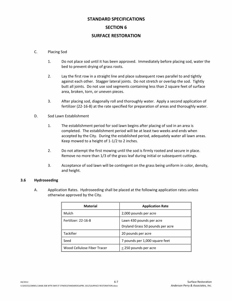
STANDARD SPECIFICATIONS
SECTION 6
SURFACE RESTORATION
04/2012 6‐7 Surface Restoration S:\DOCS\CONNELL\W68‐208 WTR SWR ST STNDS\STANDARDS\APRIL 2012\SURFACE RESTORATION.docx Anderson Perry & Associates, Inc.
C. Placing Sod
1. Do not place sod until it has been approved. Immediately before placing sod, water the bed to prevent drying of grass roots.
2. Lay the first row in a straight line and place subsequent rows parallel to and tightly against each other. Stagger lateral joints. Do not stretch or overlap the sod. Tightly butt all joints. Do not use sod segments containing less than 2 square feet of surface area, broken, torn, or uneven pieces.
3. After placing sod, diagonally roll and thoroughly water. Apply a second application of fertilizer (22‐16‐8) at the rate specified for preparation of areas and thoroughly water.
D. Sod Lawn Establishment
1. The establishment period for sod lawn begins after placing of sod in an area is completed. The establishment period will be at least two weeks and ends when accepted by the City. During the established period, adequately water all lawn areas. Keep mowed to a height of 1‐1/2 to 2 inches.
2. Do not attempt the first mowing until the sod is firmly rooted and secure in place. Remove no more than 1/3 of the grass leaf during initial or subsequent cuttings.
3. Acceptance of sod lawn will be contingent on the grass being uniform in color, density, and height.
3.6 Hydroseeding
A. Application Rates. Hydroseeding shall be placed at the following application rates unless otherwise approved by the City.
Material Application Rate
Mulch 2,000 pounds per acre
Fertilizer: 22‐16‐8 Lawn 430 pounds per acre
Dryland Grass 50 pounds per acre
Tackifier 20 pounds per acre
Seed 7 pounds per 1,000 square feet
Wood Cellulose Fiber Tracer < 250 pounds per acre
STANDARD SPECIFICATIONS
SECTION 6
SURFACE RESTORATION
04/2012 6‐8 Surface Restoration S:\DOCS\CONNELL\W68‐208 WTR SWR ST STNDS\STANDARDS\APRIL 2012\SURFACE RESTORATION.docx Anderson Perry & Associates, Inc.
B. Seeding shall not be done during windy weather or when the ground is excessively wet or otherwise un‐tillable. Seed will be placed with an approved hydroseeder which utilizes water as the carrying agent, and maintains continuous agitation through paddle blades. Hydroseeding will only be allowed from late September to mid‐November unless otherwise approved by the City.
C. Hydroseeder
1. Hydroseeder shall have an operating capacity sufficient to agitate, suspend and mix into a homogenous slurry, and the specified amount of seed and water or other material.
2. Distribution and discharge lines shall be large enough to prevent stoppage and shall be equipped with a set of hydraulic spray nozzles which will provide a uniform distribution of the slurry.
D. Seed and fertilizer may be applied in one application provided the fertilizer is placed in the hydroseeder tank no more than 30 minutes prior to application. The seed shall have a tracer added to aid uniform application. This tracer shall not be harmful to plant and animal life.
E. The Contractor shall remove mulch material which falls on plants, roadways, gravel shoulders, structures, areas where mulching is not specified, or which collects at the ends of culverts or accumulates to excessive depths, as directed.
SECTION 7 ROAD WORK
TABLE OF CONTENTS
SECTION 7
ROAD WORK
04/2012 i Table of Contents S:\DOCS\CONNELL\W68‐208 WTR SWR ST STNDS\STANDARDS\APRIL 2012\ROAD WORK.docx Anderson Perry & Associates, Inc.
PART 1 ‐ General ..................................................................................................................................................... 7‐1 1.1 Scope ...................................................................................................................................................... 7‐1 1.2 Submittals ............................................................................................................................................... 7‐1
PART 2 ‐ Materials .................................................................................................................................................. 7‐1 2.1 Aggregates .............................................................................................................................................. 7‐1 2.2 Hot Mixed Asphalt (HMA) ...................................................................................................................... 7‐1 2.3 Pavement Markings ................................................................................................................................ 7‐1 2.4 Construction Geosynthetics ................................................................................................................... 7‐1
PART 3 ‐ Execution .................................................................................................................................................. 7‐2 3.1 Clearing and Grubbing ............................................................................................................................ 7‐2 3.2 Roadway Excavation ............................................................................................................................... 7‐2 3.3 Embankment .......................................................................................................................................... 7‐2 3.4 Crushed Surfacing ................................................................................................................................... 7‐2 3.5 Hot Mix Asphalt (HMA)........................................................................................................................... 7‐2 3.6 Testing .................................................................................................................................................... 7‐3
STANDARD SPECIFICATIONS
SECTION 7
ROAD WORK
04/2012 7‐1 Road Work S:\DOCS\CONNELL\W68‐208 WTR SWR ST STNDS\STANDARDS\APRIL 2012\ROAD WORK.docx Anderson Perry & Associates, Inc.
PART 1 ‐ GENERAL
1.1 Scope
These specifications cover the construction of streets and roadways.
1.2 Submittals
Test results of all materials, and a WSDOT approved Hot Mix Asphalt design must be submitted to the City for approval, as required in Section E, Materials Submittals of the General Requirements, prior to incorporation into the work. In place test results shall also be submitted.
PART 2 ‐ MATERIALS
2.1 Aggregates
All aggregates shall conform to the material requirements as described in the current Washington State Department of Transportation Standard Specifications for Road, Bridge, and Municipal Construction. Surface aggregates shall be crushed surfacing top course. Aggregate under pavement, curbs, sidewalks, and driveways shall be crushed surfacing top course and/or crushed surfacing base course as referenced on the Standard Plans.
2.2 Hot Mixed Asphalt (HMA)
HMA shall be Class 1/2‐In., PG 64‐28, and shall be designed for no less than 0.8 million ESAL’s, unless otherwise required by or approved by the City. All materials incorporated into the HMA shall conform to the material requirements as described in the current Washington State Department of Transportation Standard Specifications for Road, Bridge, and Municipal Construction.
2.3 Pavement Markings
Temporary marking materials, glass beads, and paints for pavement markings shall conform to the material requirements as described in the current Washington State Department of Transportation Standard Specifications for Road, Bridge, and Municipal Construction.
2.4 Construction Geosynthetics
Construction geosynthetics shall conform to the material requirements as described in the current Washington State Department of Transportation Standard Specifications for Road, Bridge, and Municipal Construction. The applicable table shall be specified based on the intended use and need.
STANDARD SPECIFICATIONS
SECTION 7
ROAD WORK
04/2012 7‐2 Road Work S:\DOCS\CONNELL\W68‐208 WTR SWR ST STNDS\STANDARDS\APRIL 2012\ROAD WORK.docx Anderson Perry & Associates, Inc.
PART 3 ‐ EXECUTION
3.1 Clearing and Grubbing
All areas to be surfaced shall be cleared and grubbed. All organic material shall be completely removed and disposed of in accordance with federal, state, and local regulations.
3.2 Roadway Excavation
Areas to be surfaced shall be excavated to the lines and grades designated on the approved plans. Excess material shall be hauled off site and disposed of in accordance with federal, state, and local regulations. When rock or other hard material is encountered at subgrade elevation, it shall be excavated the full width of the roadbed to at least 6 inches below subgrade and backfilled with crushed gravel or common borrow material. Any soft or uncompactable material found shall also be removed and replaced with compactable, free draining material. After the subgrade is cut to grade it shall be compacted to 90 percent of standard density as determined by Section 2‐03.3(14)D of the WSDOT Standard Specifications.
3.3 Embankment
Areas on which embankments are to be constructed shall be cleared and grubbed and all organic material removed. The subgrade shall be compacted to 90 percent of maximum density. Embankments shall be constructed in accordance with Section 2‐03.3(14) Method B, of the current Washington State Department of Transportation Standard Specifications for Road, Bridge, and Municipal Construction.
3.4 Crushed Surfacing
The subgrade shall be properly prepared, tested, and approved by the City of Connell prior to the placement of any surfacing materials. Each layer surfacing shall be properly shaped and compacted to at least 95 percent of maximum density as determined by Section 2‐03.3(14)D of the WSDOT Standard Specificiations.
3.5 Hot Mix Asphalt (HMA)
HMA shall be placed and compacted in accordance with Section 5‐04 of the current Washington State Department of Transportation Standard Specifications for Road, Bridge, and Municipal Construction. Any HMA placed in travel lanes that fails to meet the acceptance criteria for nonstatistical evaluation may be rejected by the City. Corrective action required for HMA not meeting the specifications will be at the sole discretion of the City. All HMA testing required shall be performed by an independent contractor and submitted to the City.
STANDARD SPECIFICATIONS
SECTION 7
ROAD WORK
04/2012 7‐3 Road Work S:\DOCS\CONNELL\W68‐208 WTR SWR ST STNDS\STANDARDS\APRIL 2012\ROAD WORK.docx Anderson Perry & Associates, Inc.
3.6 Testing
All materials testing shall be performed at the frequency and method specified in the WSDOT Construction Manual and the current Washington State Department of Transportation Standard Specifications for Road, Bridge, and Municipal Construction for the various materials used. Testing shall be performed by a company certified to perform the required test methods and procedures.

STANDARD PLANS

GENERAL
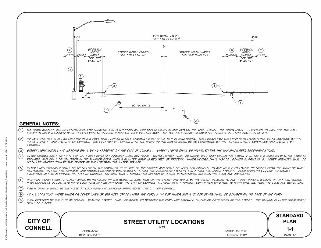
GENERAL NOTES:
1-1
STREET UTILITY LOCATIONS
REVISION DATE APPROVED BY
CITY OF
CONNELL
STANDARD
PLAN
PAGE 1-1
NTS
APRIL 2012 LARRY TURNER
R:\C
lients\C
onnell\W
68-208 C
onnell S
tandard D
etails\1-1 G
eneral_S
treet U
tility Location.dw
g, 4/19/2012 2:07:39 P
M
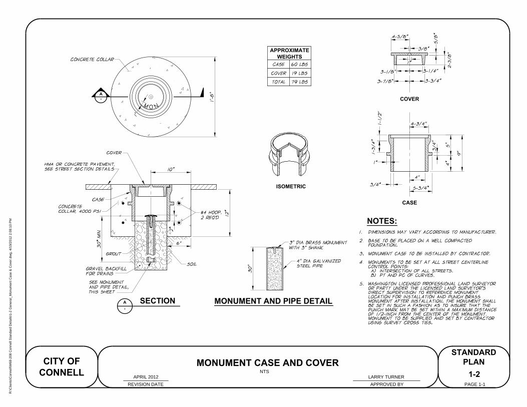
A
-
SECTIONA
-
APPROXIMATE
WEIGHTS
ISOMETRIC
CASE
MONUMENT AND PIPE DETAIL
COVER
NOTES:
MONUMENT CASE AND COVER
NTS
1-2
REVISION DATE APPROVED BY
CITY OF
CONNELL
STANDARD
PLAN
PAGE 1-1
LARRY TURNERAPRIL 2012
R:\C
lients\C
onnell\W
68-208 C
onnell S
tandard D
etails\1-2 G
eneral_M
onum
ent C
ase &
C
over.dw
g, 4/19/2012 2:08:10 P
M
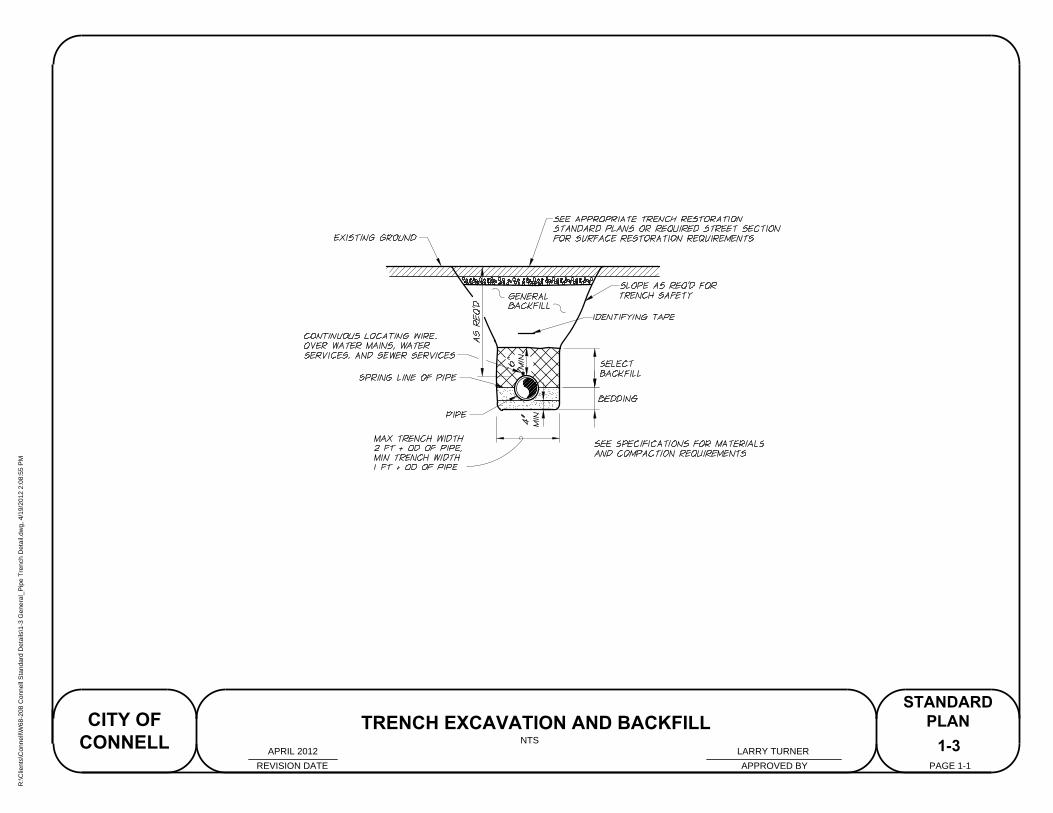
TRENCH EXCAVATION AND BACKFILL
STANDARD
PLAN
PAGE 1-1
NTS
1-3
REVISION DATE APPROVED BY
CITY OF
CONNELL
LARRY TURNERAPRIL 2012
R:\C
lients\C
onnell\W
68-208 C
onnell S
tandard D
etails\1-3 G
eneral_P
ipe T
rench D
etail.dw
g, 4/19/2012 2:08:55 P
M
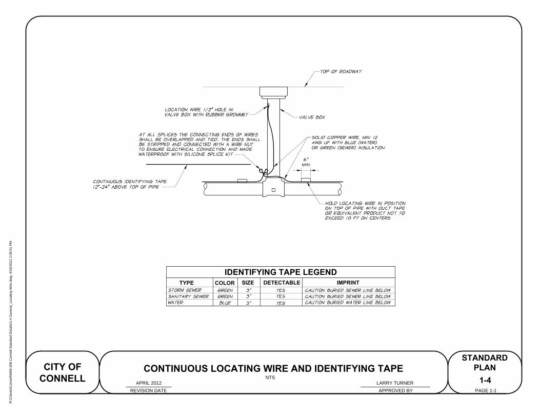
1-4
REVISION DATE APPROVED BY
CITY OF
CONNELL
STANDARD
PLAN
PAGE 1-1
CONTINUOUS LOCATING WIRE AND IDENTIFYING TAPE
TYPE COLORSIZE
IDENTIFYING TAPE LEGEND
DETECTABLE IMPRINT
NTS
LARRY TURNERAPRIL 2012
R:\C
lients\C
onnell\W
68-208 C
onnell S
tandard D
etails\1-4 G
eneral_Locating W
ire.dw
g, 4/19/2012 2:09:51 P
M
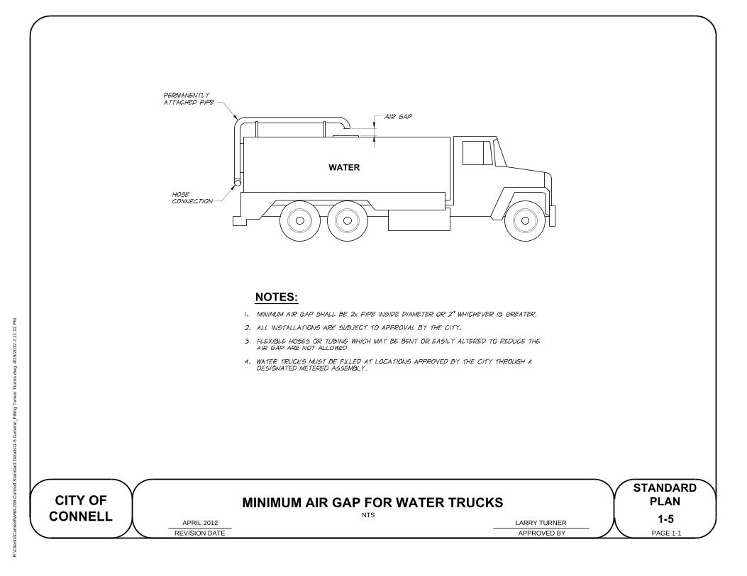
WATER
NOTES:
1-5
REVISION DATE APPROVED BY
CITY OF
CONNELL
STANDARD
PLAN
PAGE 1-1
MINIMUM AIR GAP FOR WATER TRUCKS
NTS
LARRY TURNERAPRIL 2012
R:\C
lients\C
onnell\W
68-208 C
onnell S
tandard D
etails\1-5 G
eneral_F
illing T
anker T
rucks.dw
g, 4/19/2012 2:11:12 P
M
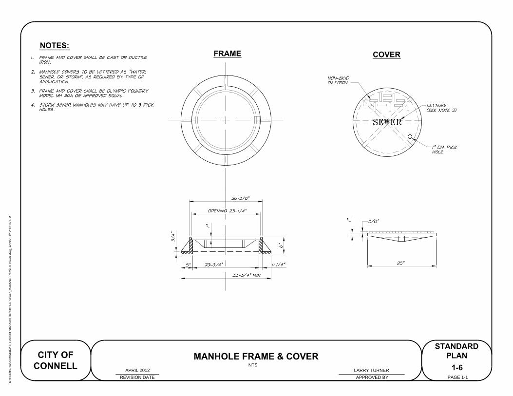
FRAME
COVER
NOTES:
1-6
MANHOLE FRAME & COVER
REVISION DATE APPROVED BY
CITY OF
CONNELL
STANDARD
PLAN
PAGE 1-1
NTS
LARRY TURNERAPRIL 2012
R:\C
lients\C
onnell\W
68-208 C
onnell S
tandard D
etails\1-6 S
ew
er_M
anhole F
ram
e &
C
over.dw
g, 4/19/2012 2:12:07 P
M
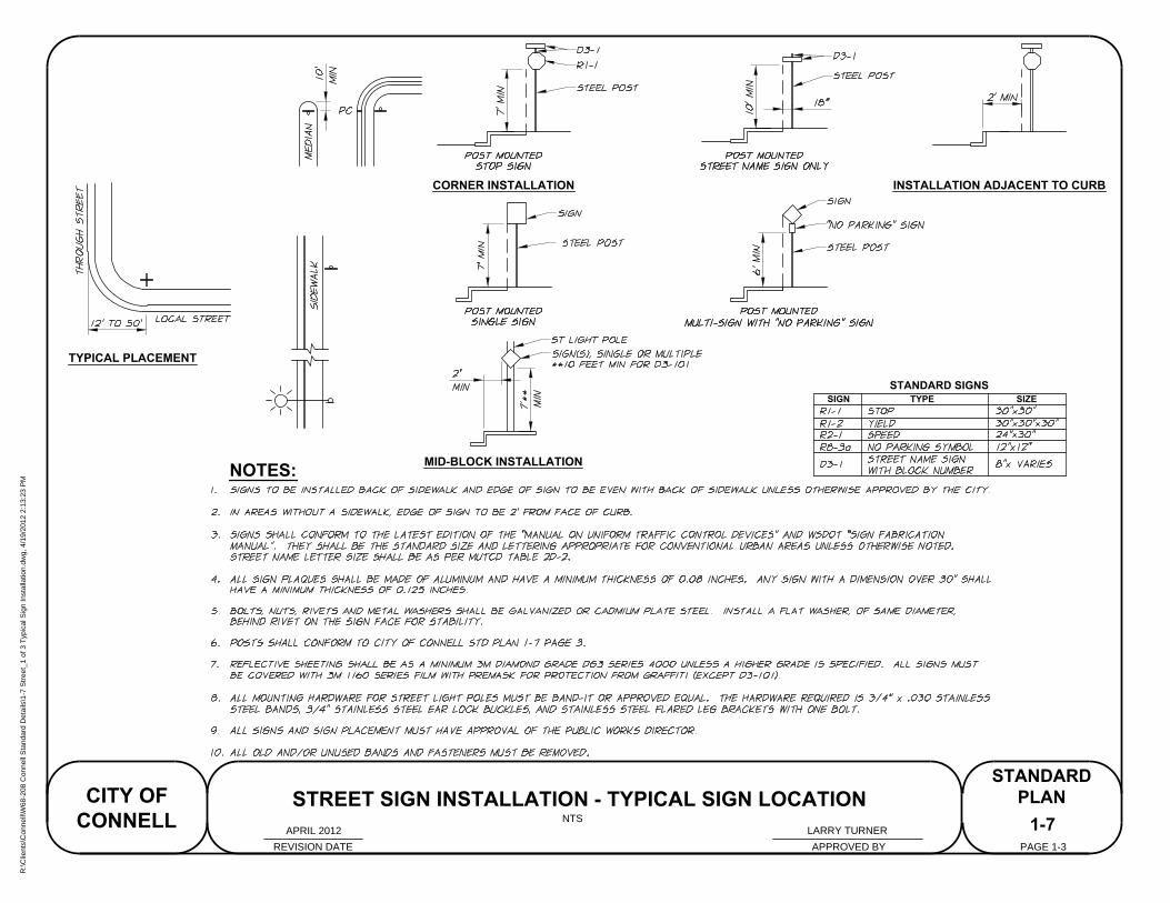
CORNER INSTALLATION
MID-BLOCK INSTALLATION
SIGN TYPE SIZE
STANDARD SIGNS
NOTES:
TYPICAL PLACEMENT
INSTALLATION ADJACENT TO CURB
1-7
REVISION DATE APPROVED BY
CITY OF
CONNELL
STANDARD
PLAN
PAGE 1-3
NTS
STREET SIGN INSTALLATION - TYPICAL SIGN LOCATION
LARRY TURNERAPRIL 2012
R:\C
lients\C
onnell\W
68-208 C
onnell S
tandard D
etails\1-7 S
treet_1 of 3 T
ypical S
ign Installation.dw
g, 4/19/2012 2:13:23 P
M
STREET SIGN BRACKETS
STREET NAME SIGN
(D3-1)
NOTES:
1800
1-7
REVISION DATE APPROVED BY
CITY OF
CONNELL
STANDARD
PLAN
PAGE 2-3
NTS
STREET SIGN INSTALLATION - STREET NAME SIGN
LARRY TURNERAPRIL 2012
R:\C
lients\C
onnell\W
68-208 C
onnell S
tandard D
etails\1-7 S
treet_2 of 3 S
treet N
am
e S
ign.dw
g, 4/19/2012 2:14:09 P
M
DRIVE RIVET
LENGTHPART TUBE SIZE
MIN. WALL
THICKNESS
1-7
STREET SIGN INSTALLATION - TYPICAL SIGN POST
REVISION DATE APPROVED BY
CITY OF
CONNELL
STANDARD
PLAN
PAGE 3-3
NTS
NOTES:
LARRY TURNERAPRIL 2012
R:\C
lients\C
onnell\W
68-208 C
onnell S
tandard D
etails\1-7 S
treet_3 of 3 T
ypical S
ign P
ost.dw
g, 4/19/2012 2:14:49 P
M
1-8
STORM DRAIN INLET PROTECTION
REVISION DATE
STANDARD
PLAN
PAGE 1-1
NTS
APPROVED BY
CITY OF
CONNELL
NOTES:
LARRY TURNERAPRIL 2012
R:\C
lients\C
onnell\W
68-208 C
onnell S
tandard D
etails\1-8 G
eneral_S
torm
D
rain Inlet P
rotection.dw
g, 4/19/2012 2:15:24 P
M

STREET
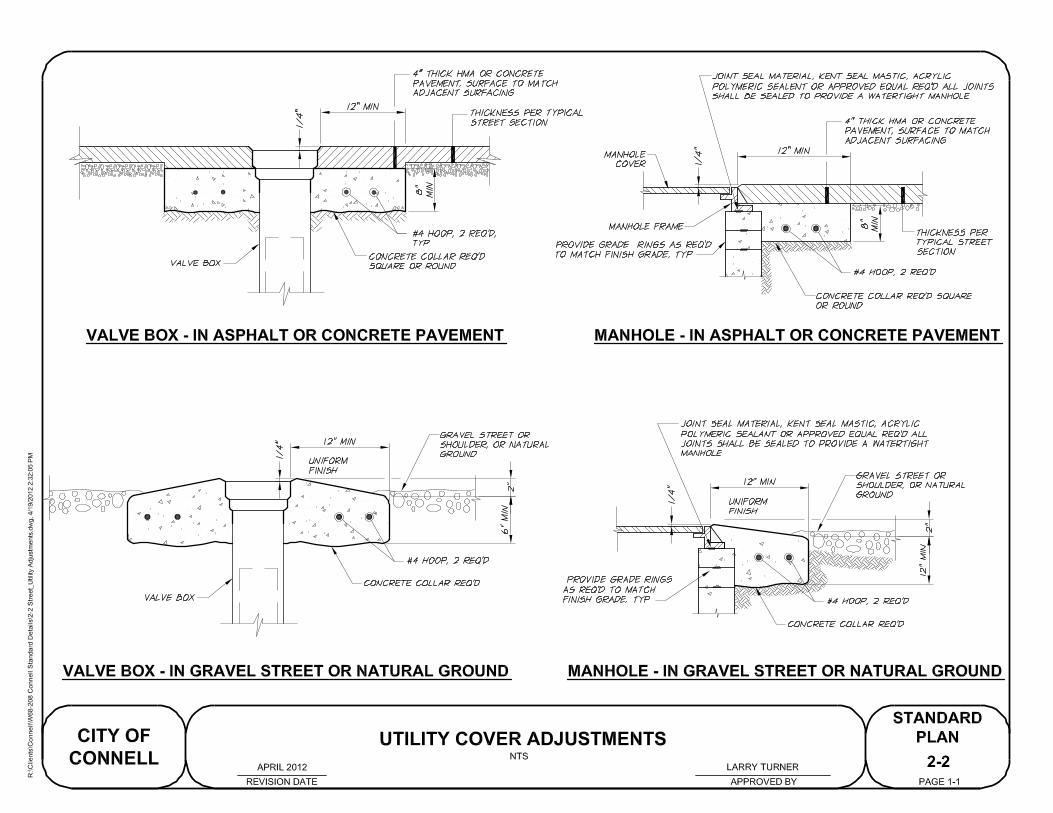
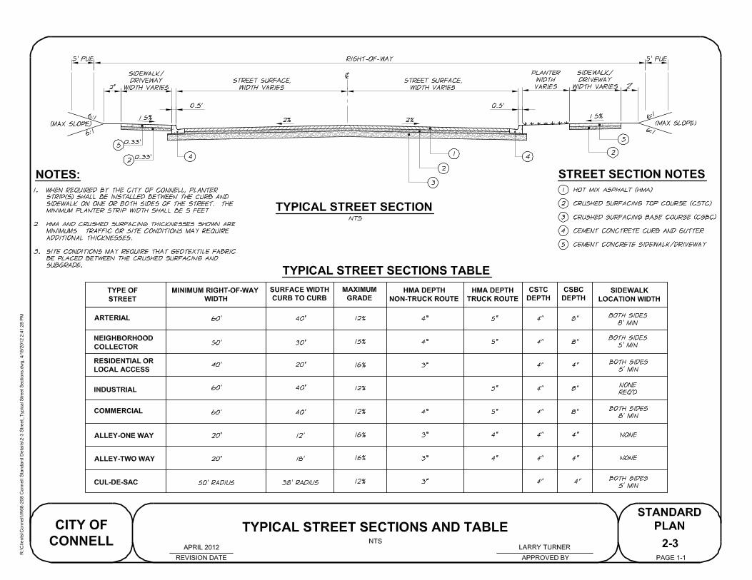
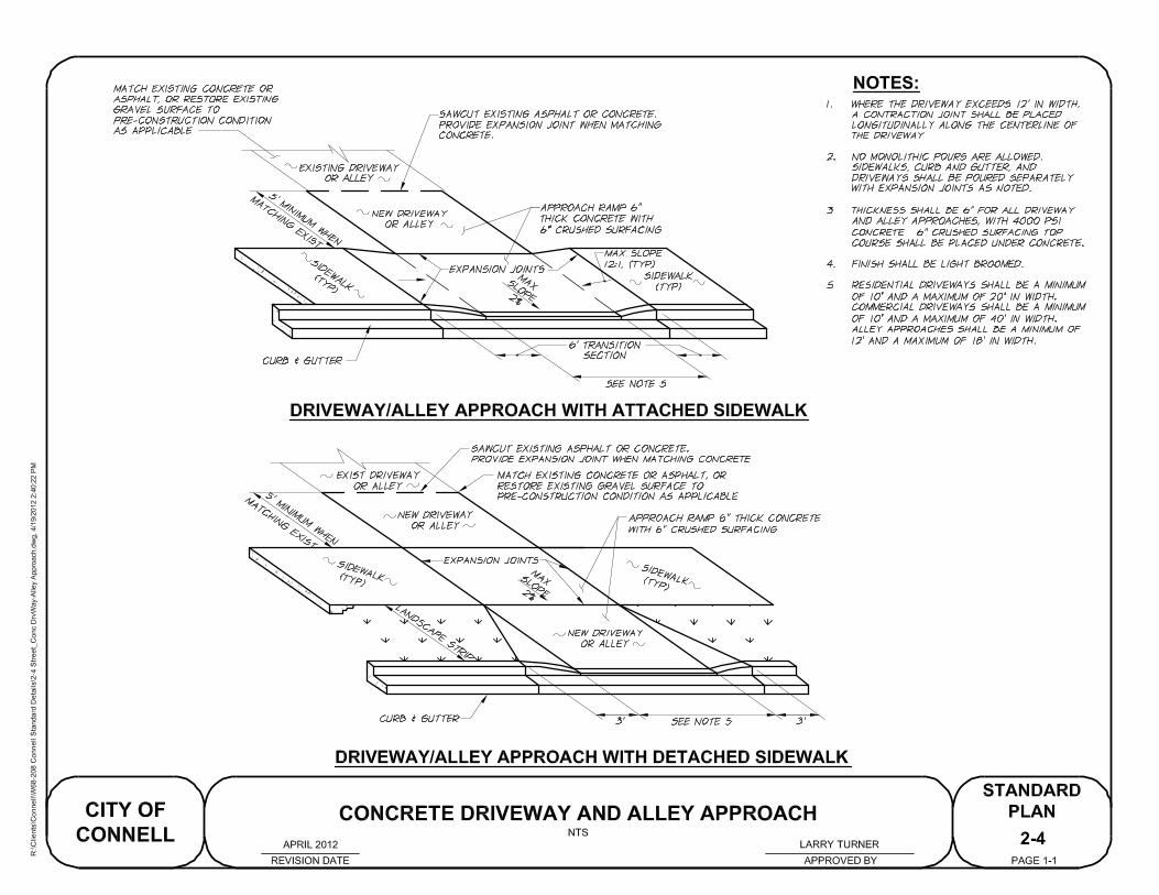
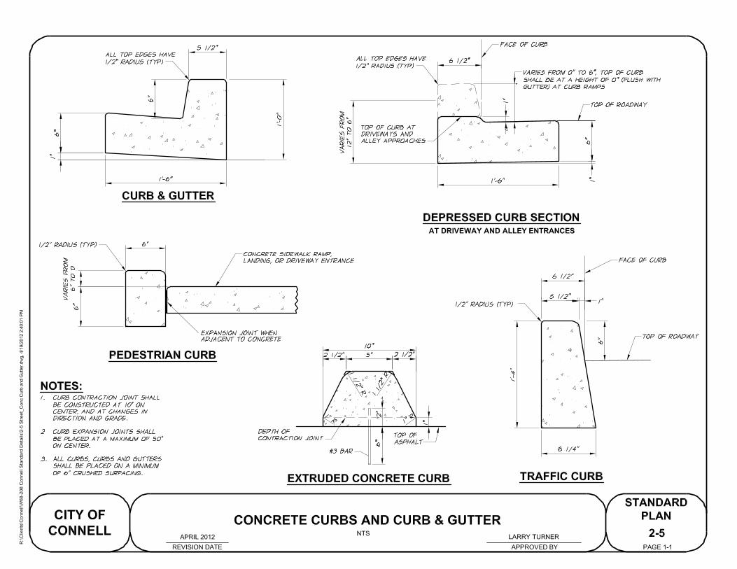
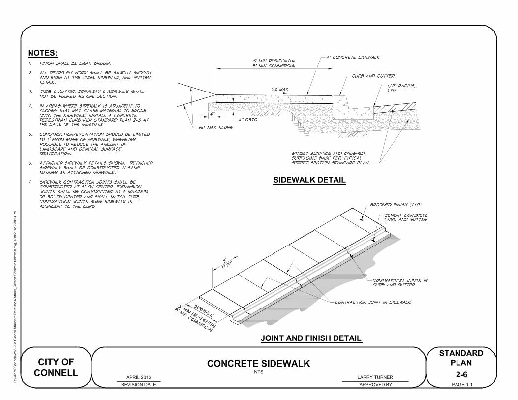
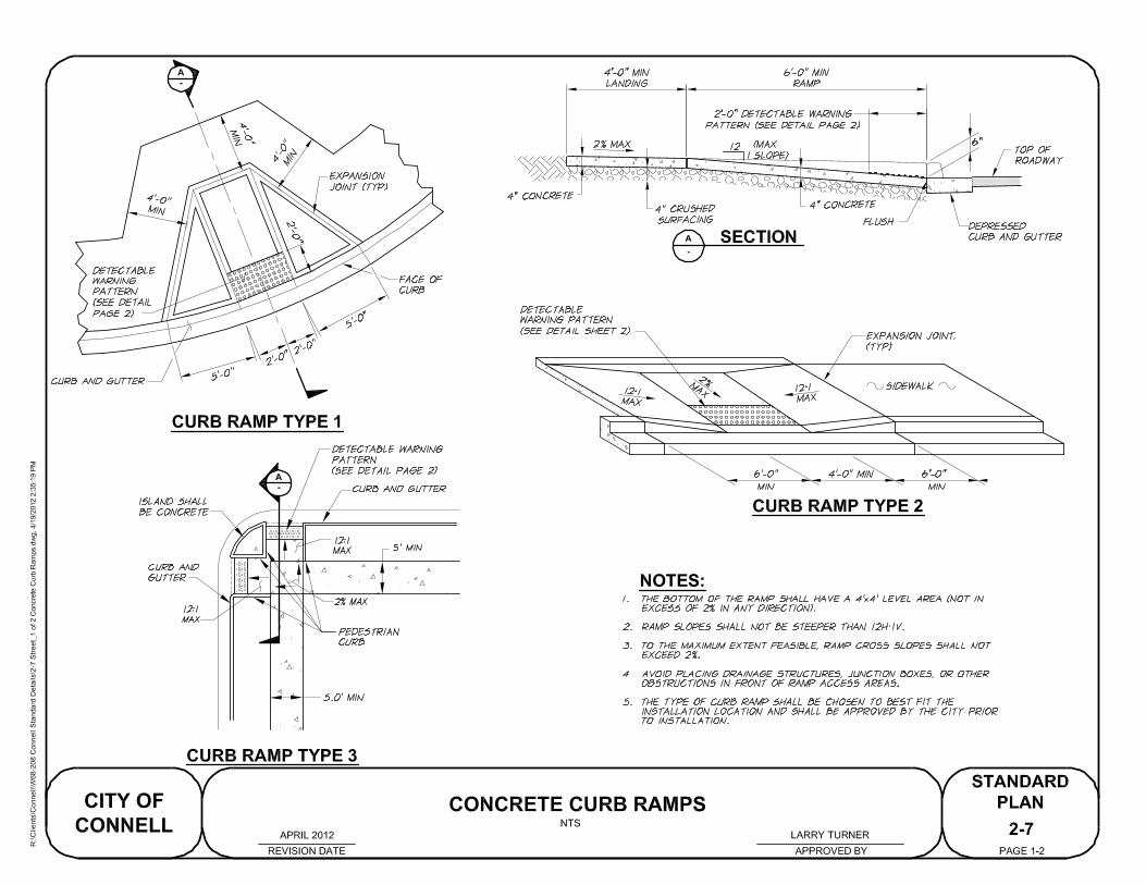
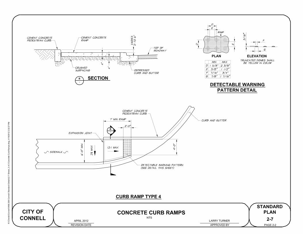
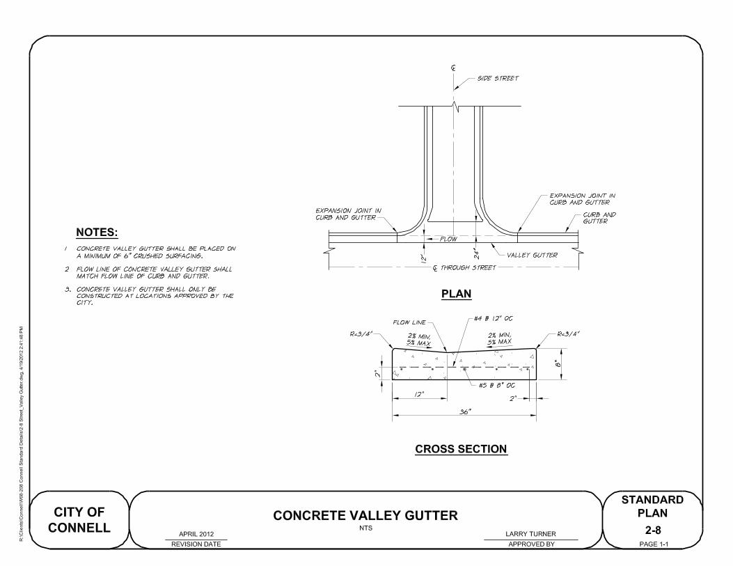
WATER
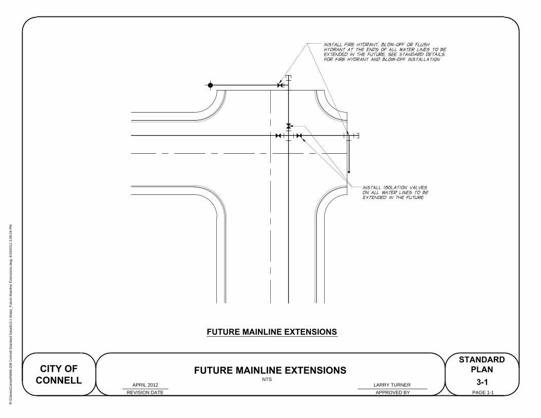
FUTURE MAINLINE EXTENSIONS
3-1
FUTURE MAINLINE EXTENSIONS
REVISION DATE APPROVED BY
CITY OF
CONNELL
STANDARD
PLAN
PAGE 1-1
NTS
LARRY TURNERAPRIL 2012
R:\C
lients\C
onnell\W
68-208 C
onnell S
tandard D
etails\3-1 W
ater_F
uture M
ainline E
xtensions.dw
g, 4/19/2012 3:09:24 P
M
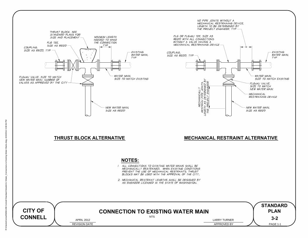
THRUST BLOCK ALTERNATIVE MECHANICAL RESTRAINT ALTERNATIVE
NOTES:
3-2
REVISION DATE APPROVED BY
CITY OF
CONNELL
STANDARD
PLAN
PAGE 1-1
CONNECTION TO EXISTING WATER MAIN
NTS
LARRY TURNERAPRIL 2012
R:\C
lients\C
onnell\W
68-208 C
onnell S
tandard D
etails\3-2 W
ater_C
onnections to E
xisting W
ater M
ains.dw
g, 4/19/2012 3:08:56 P
M
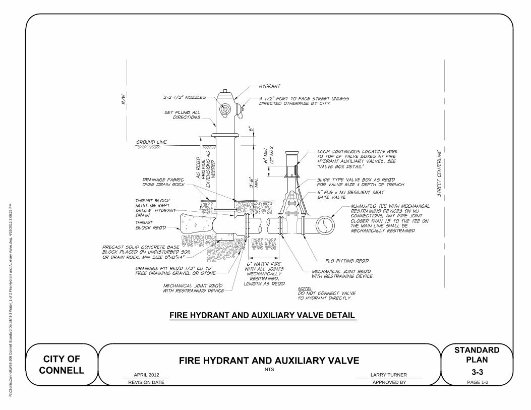
FIRE HYDRANT AND AUXILIARY VALVE DETAIL
3-3
REVISION DATE APPROVED BY
CITY OF
CONNELL
STANDARD
PLAN
PAGE 1-2
FIRE HYDRANT AND AUXILIARY VALVE
NTS
LARRY TURNERAPRIL 2012
R:\C
lients\C
onnell\W
68-208 C
onnell S
tandard D
etails\3-3 W
ater_1 of 2 F
ire H
ydrant and A
uxiliary V
alve.dw
g, 4/19/2012 3:08:25 P
M
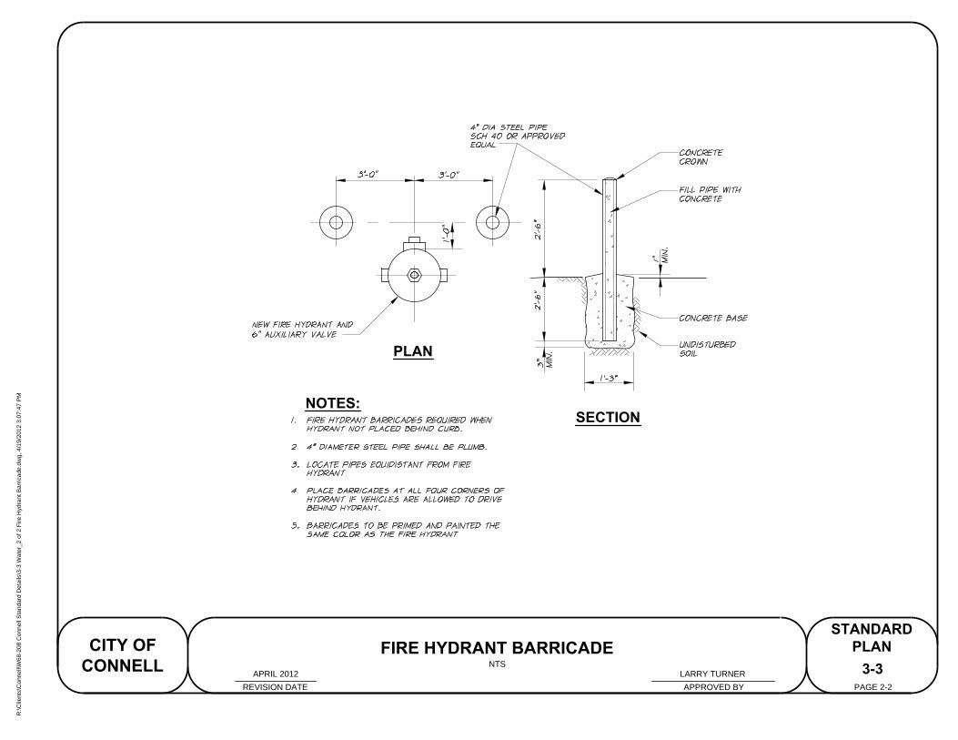
PLAN
SECTION
NOTES:
3-3
REVISION DATE APPROVED BY
CITY OF
CONNELL
STANDARD
PLAN
PAGE 2-2
FIRE HYDRANT BARRICADE
NTS
LARRY TURNERAPRIL 2012
R:\C
lients\C
onnell\W
68-208 C
onnell S
tandard D
etails\3-3 W
ater_2 of 2 F
ire H
ydrant B
arricade.dw
g, 4/19/2012 3:07:47 P
M
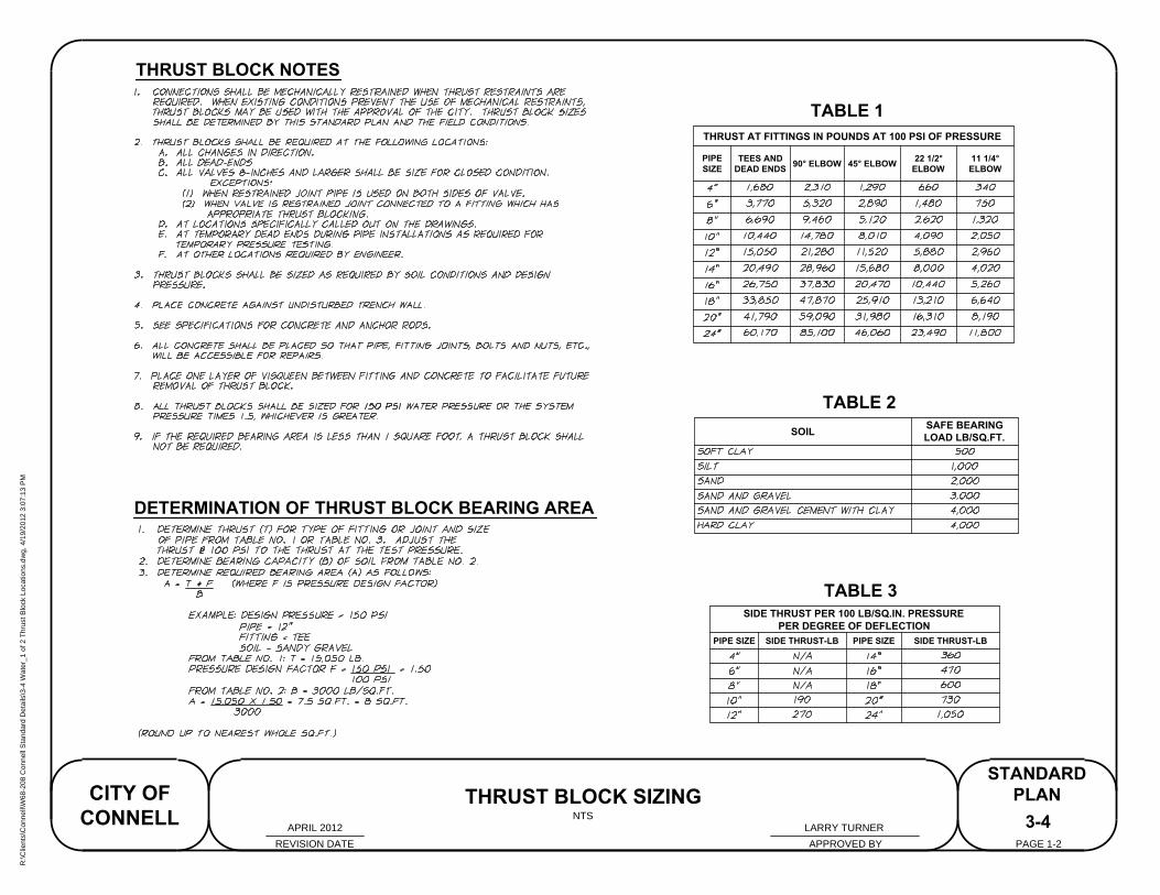
THRUST BLOCK NOTES
DETERMINATION OF THRUST BLOCK BEARING AREA
SIDE THRUST PER 100 LB/SQ.IN. PRESSURE
PER DEGREE OF DEFLECTION
PIPE SIZE SIDE THRUST-LB PIPE SIZE SIDE THRUST-LB
THRUST AT FITTINGS IN POUNDS AT 100 PSI OF PRESSURE
PIPE
SIZE
TEES AND
DEAD ENDS
90° ELBOW 45° ELBOW
22 1/2°
ELBOW
11 1/4°
ELBOW
SOIL
SAFE BEARING
LOAD LB/SQ.FT.
TABLE 1
TABLE 2
TABLE 3
3-4
THRUST BLOCK SIZING
REVISION DATE APPROVED BY
CITY OF
CONNELL
STANDARD
PLAN
PAGE 1-2
NTS
LARRY TURNERAPRIL 2012
R:\C
lients\C
onnell\W
68-208 C
onnell S
tandard D
etails\3-4 W
ater_1 of 2 T
hrust B
lock Locations.dw
g, 4/19/2012 3:07:13 P
M
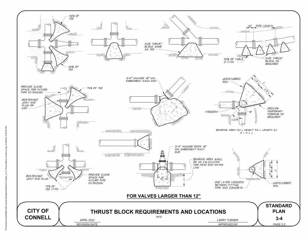
FOR VALVES LARGER THAN 12"
3-4
REVISION DATE APPROVED BY
CITY OF
CONNELL
STANDARD
PLAN
PAGE 2-2
THRUST BLOCK REQUIREMENTS AND LOCATIONS
NTS
LARRY TURNERAPRIL 2012
R:\C
lients\C
onnell\W
68-208 C
onnell S
tandard D
etails\3-4 W
ater_2 of 2 T
hrust B
lock Locations.dw
g, 4/19/2012 3:06:36 P
M
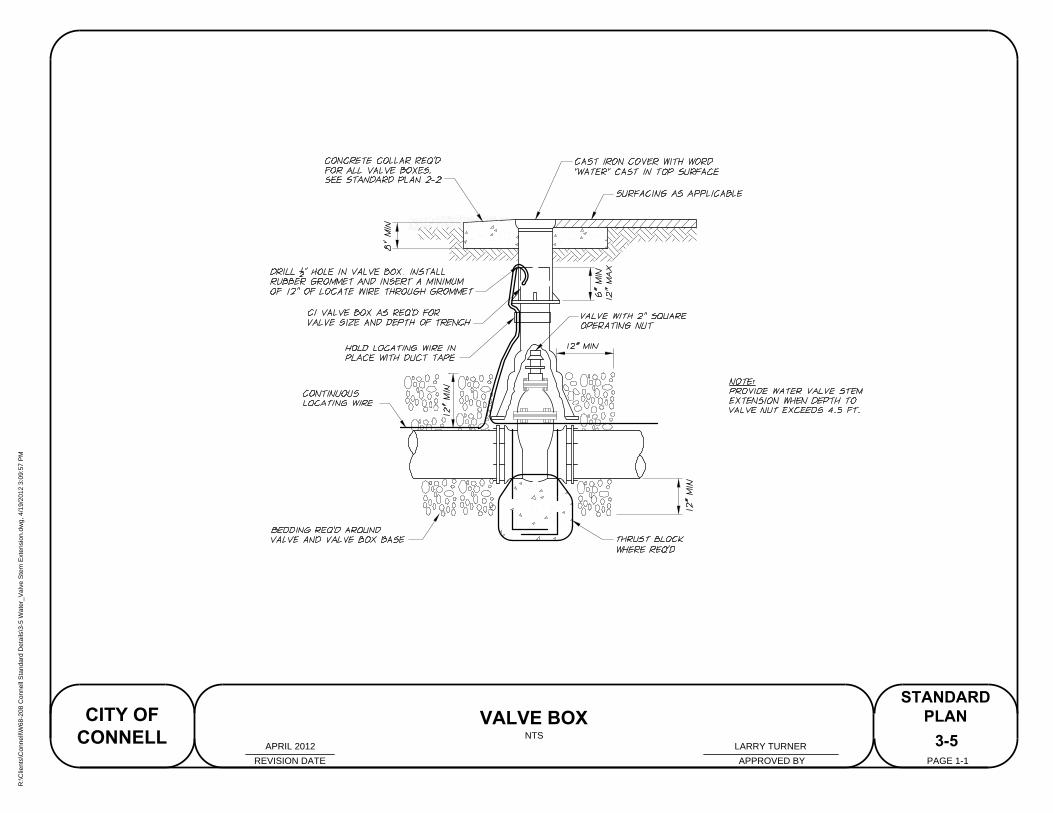
3-5
REVISION DATE APPROVED BY
CITY OF
CONNELL
STANDARD
PLAN
PAGE 1-1
VALVE BOX
NTS
LARRY TURNERAPRIL 2012
R:\C
lients\C
onnell\W
68-208 C
onnell S
tandard D
etails\3-5 W
ater_V
alve S
tem
E
xtension.dw
g, 4/19/2012 3:09:57 P
M
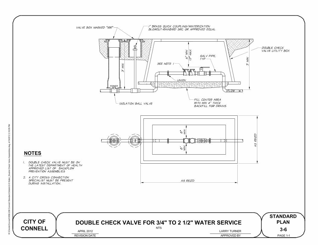
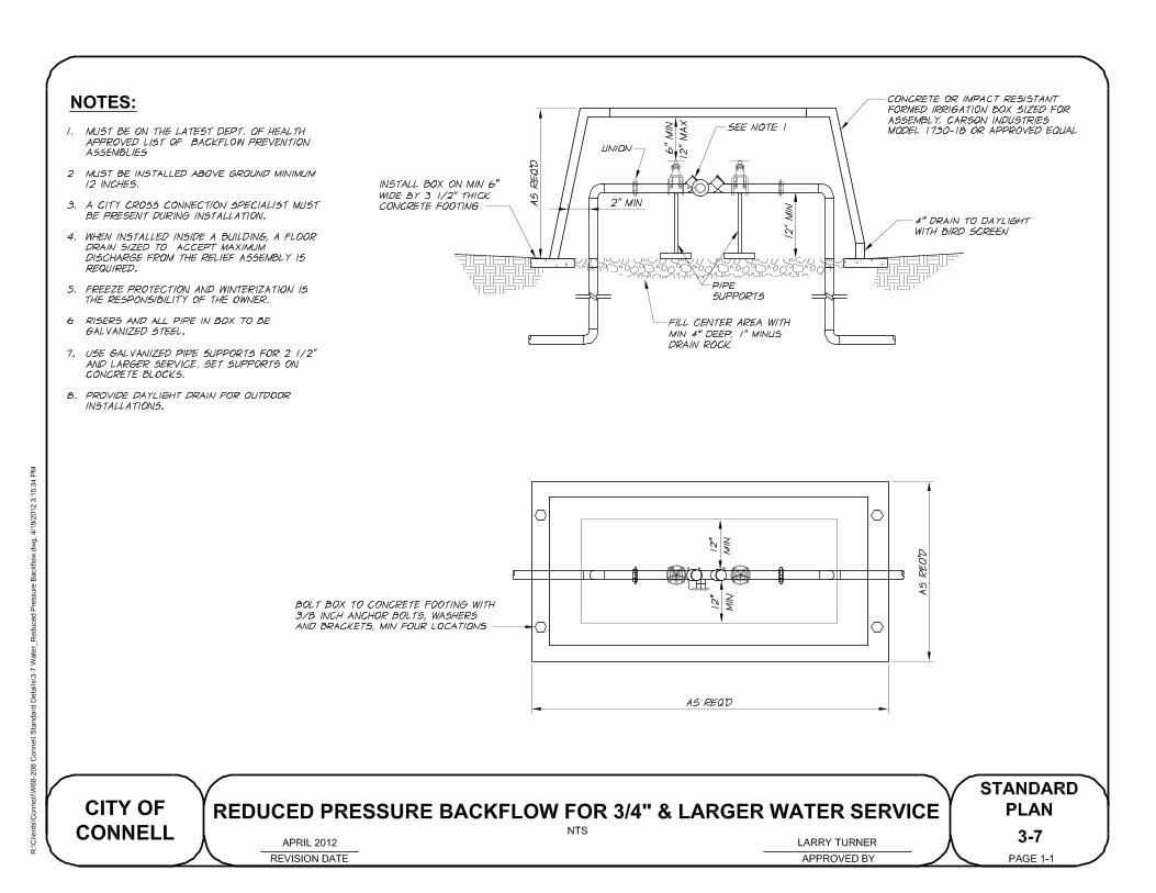
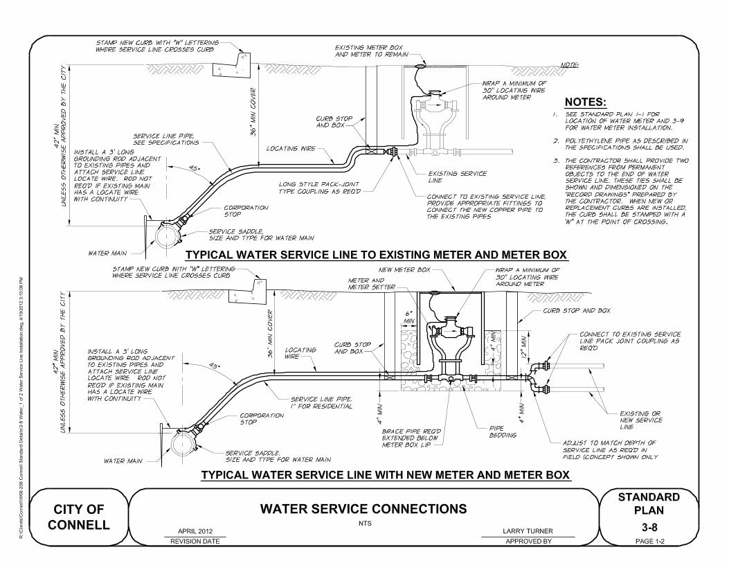
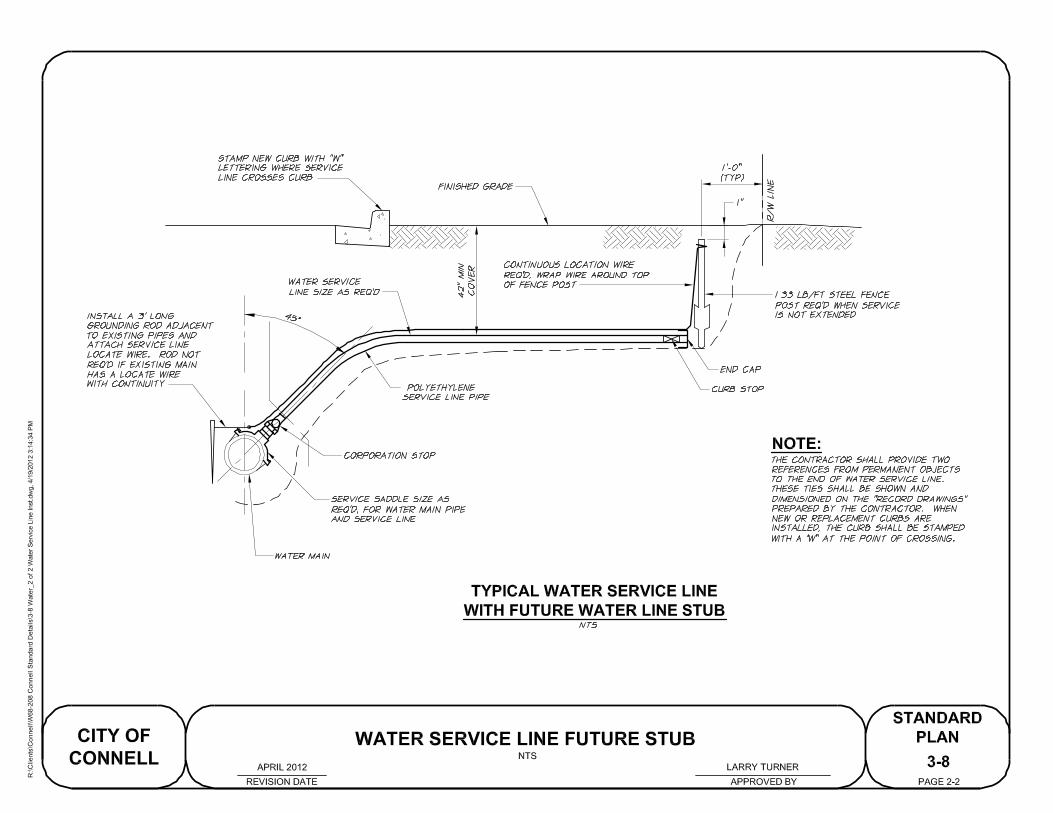
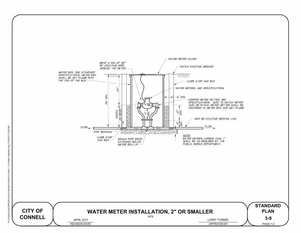
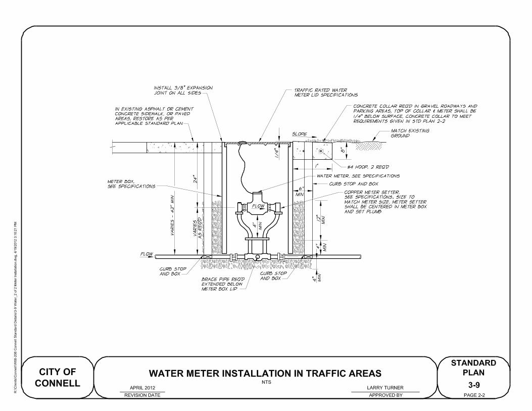
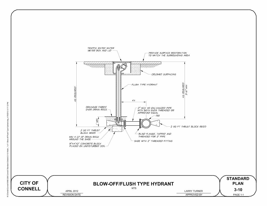
SANITARY SEWER
4-1
SANITARY SEWER CLEANOUT
REVISION DATE APPROVED BY
CITY OF
CONNELL
STANDARD
PLAN
PAGE 1-1
NTS
LARRY TURNERAPRIL 2012
R:\C
lients\C
onnell\W
68-208 C
onnell S
tandard D
etails\4-1 S
ew
er_S
anitary S
ew
er C
leanout.dw
g, 4/19/2012 3:01:50 P
M
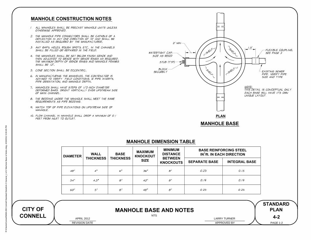
MANHOLE BASE
PLAN
MANHOLE BASE AND NOTES
REVISION DATE
CITY OF
CONNELL
STANDARD
PLAN
PAGE 1-2
NTS
MANHOLE DIMENSION TABLE
DIAMETER
WALL
THICKNESS
BASE
THICKNESS
MAXIMUM
KNOCKOUT
SIZE
MINIMUM
DISTANCE
BETWEEN
KNOCKOUTS
BASE REINFORCING STEEL
IN /ft. IN EACH DIRECTION
SEPARATE BASE INTEGRAL BASE
2
4-2
APPROVED BY
MANHOLE CONSTRUCTION NOTES
LARRY TURNERAPRIL 2012
R:\C
lients\C
onnell\W
68-208 C
onnell S
tandard D
etails\4-2 G
eneral_1 of 2 M
anhole B
ase &
N
otes.dw
g, 4/19/2012 3:00:45 P
M
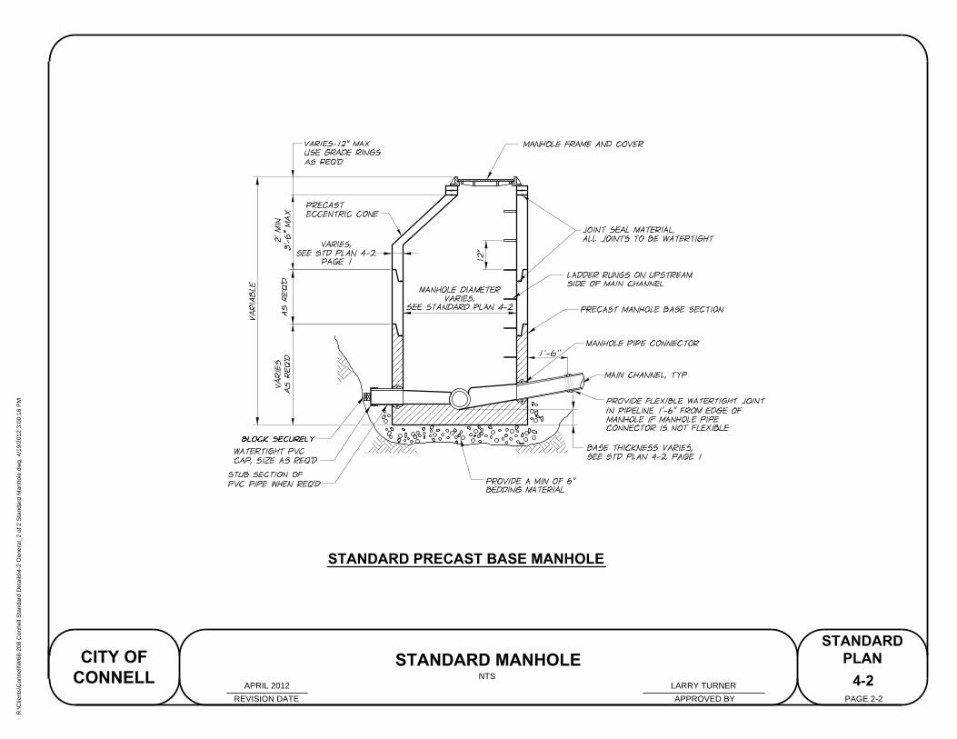
STANDARD PRECAST BASE MANHOLE
STANDARD MANHOLE
REVISION DATE
CITY OF
CONNELL
STANDARD
PLAN
PAGE 2-2
NTS
4-2
APPROVED BY
LARRY TURNERAPRIL 2012
R:\C
lients\C
onnell\W
68-208 C
onnell S
tandard D
etails\4-2 G
eneral_2 of 2 S
tandard M
anhole.dw
g, 4/19/2012 3:00:16 P
M
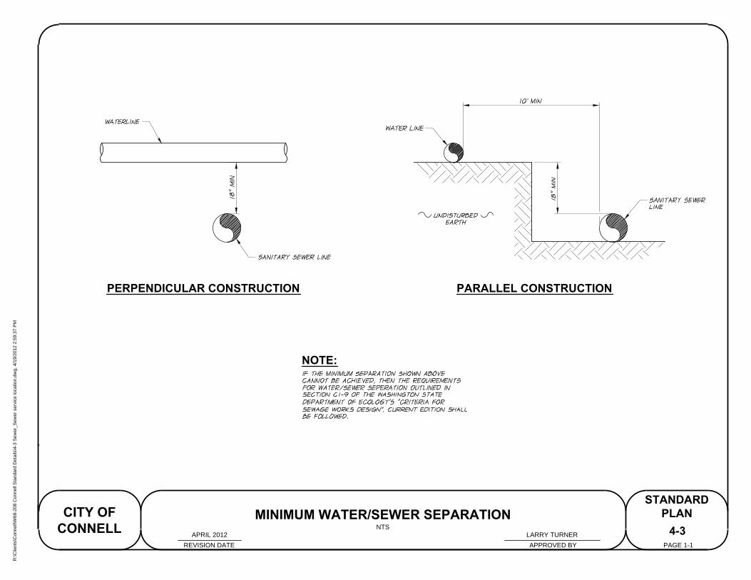
PERPENDICULAR CONSTRUCTION PARALLEL CONSTRUCTION
NOTE:
4-3
REVISION DATE APPROVED BY
CITY OF
CONNELL
STANDARD
PLAN
PAGE 1-1
MINIMUM WATER/SEWER SEPARATION
NTS
LARRY TURNERAPRIL 2012
R:\C
lients\C
onnell\W
68-208 C
onnell S
tandard D
etails\4-3 S
ew
er_S
ew
er service location.dw
g, 4/19/2012 2:59:37 P
M
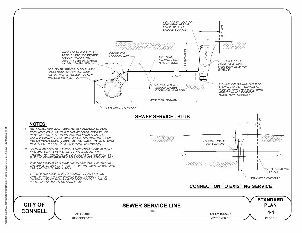
NOTES:
CONNECTION TO EXISTING SERVICE
SEWER SERVICE - STUB
4-4
SEWER SERVICE LINE
REVISION DATE APPROVED BY
CITY OF
CONNELL
STANDARD
PLAN
PAGE 1-1
NTS
LARRY TURNERAPRIL 2012
R:\C
lients\C
onnell\W
68-208 C
onnell S
tandard D
etails\4-4 S
ew
er_S
ervice Line C
onnection.dw
g, 4/19/2012 2:58:48 P
M

STORM SEWER
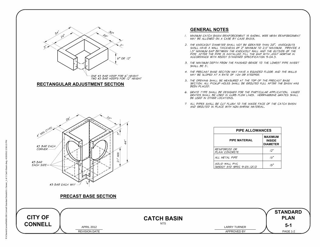
GENERAL NOTES
PIPE ALLOWANCES
PIPE MATERIAL
MAXIMUM
INSIDE
DIAMETER
RECTANGULAR ADJUSTMENT SECTION
PRECAST BASE SECTION
5-1
REVISION DATE APPROVED BY
CITY OF
CONNELL
STANDARD
PLAN
PAGE 1-2
CATCH BASIN
NTS
LARRY TURNERAPRIL 2012
R:\C
lients\C
onnell\W
68-208 C
onnell S
tandard D
etails\5-1 S
ew
er_1 of 2 C
atch B
asin.dw
g, 4/19/2012 2:58:13 P
M
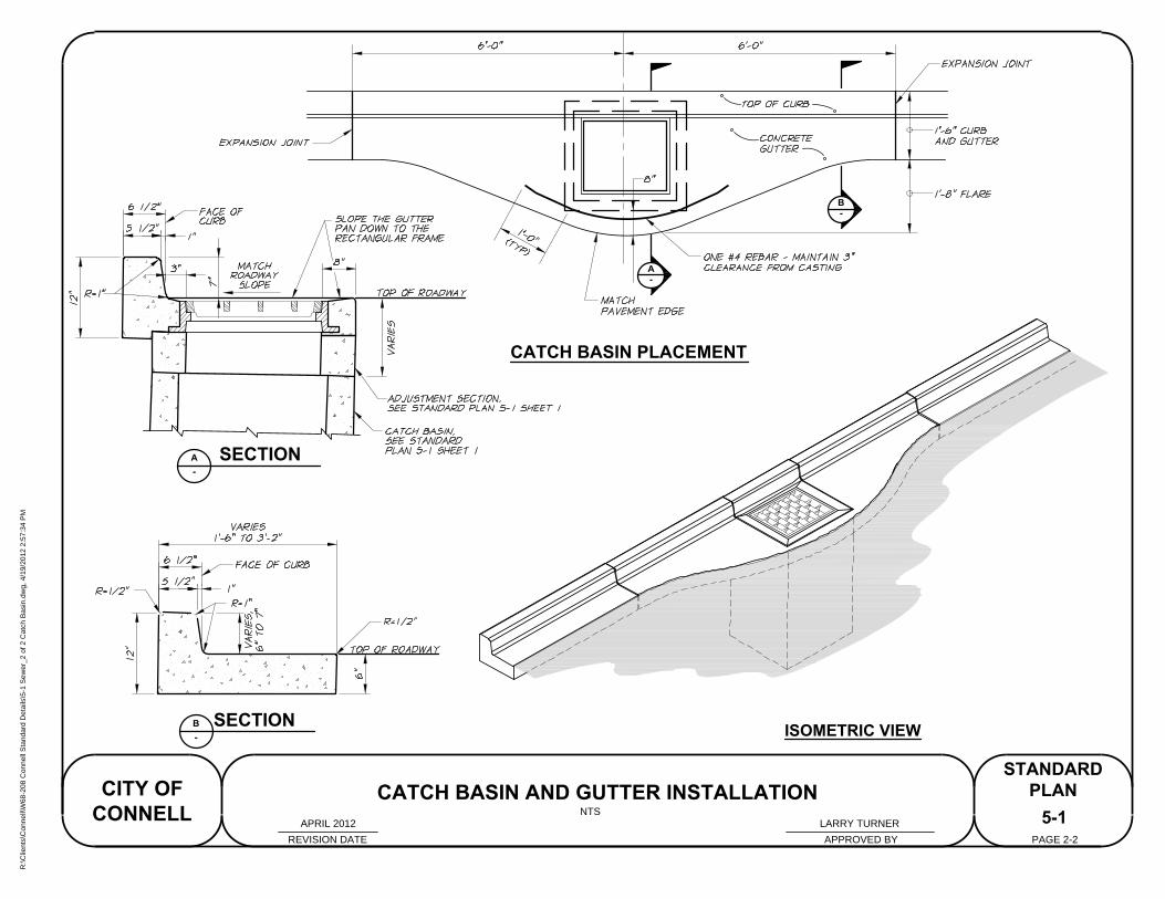
ISOMETRIC VIEW
CATCH BASIN PLACEMENT
5-1
REVISION DATE APPROVED BY
CITY OF
CONNELL
STANDARD
PLAN
PAGE 2-2
CATCH BASIN AND GUTTER INSTALLATION
A
-
SECTIONA
-
B
-
SECTIONB
-
NTS
LARRY TURNERAPRIL 2012
R:\C
lients\C
onnell\W
68-208 C
onnell S
tandard D
etails\5-1 S
ew
er_2 of 2 C
atch B
asin.dw
g, 4/19/2012 2:57:34 P
M

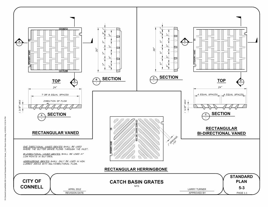
A
-
B
-
TOP
C
-
D
-
TOP
RECTANGULAR HERRINGBONE
RECTANGULAR
BI-DIRECTIONAL VANED
RECTANGULAR VANED
SECTIONA
-
SECTIONB
-
SECTIOND
-
SECTIONC
-
5-3
CATCH BASIN GRATES
REVISION DATE APPROVED BY
CITY OF
CONNELL
STANDARD
PLAN
PAGE 1-1
NTS
LARRY TURNERAPRIL 2012
R:\C
lients\C
onnell\W
68-208 C
onnell S
tandard D
etails\5-3 S
ew
er_C
atch B
asin G
rates.dw
g, 4/19/2012 3:02:54 P
M