Embed Size (px)
Citation preview

GEO-fl ow ® Pipe Leaching SystemSpecifi cations & Features
Design & Installation Manual – Vermont
2
ADS, Inc. • 58 Wyoming Street, Ludlow, Massachusetts 01056 • 800-733-3555 • www.ads-pipe.com
I. Introduction 2
II. The GEO-flow Pipe Leaching System 3
III. GEO-flow Pipe Leaching System Specifications 4
IV. GEO-flow Pipe Leaching System Schematic 5
V. Basic Design Considerations 5
VI. Vermont State-Specific Considerations 6
VII. Sizing the GEO-flow Pipe System 7
VIII. Installation Instructions 10
IX. System Configurations 11
X. Appendix I - Installation Report Form 17
XI. Appendix II - Technology Inspection Form 18-19
Contents
The purpose of this manual is to provide the minimum design and installation information for the use of the GEO-flow® Pipe Leaching System in the State of Vermont. Any exceptions or changes to the design or procedures must be confirmed by ADS, Inc. Any revised version of this manual supersedes all previous versions.
This manual provides a brief description of the GEO-flow Pipe Leaching System and its applications in Vermont. For more information, or for answers to questions or concerns, please call our Northeast Zone office at the number listed below, or contact your local sales representative.
The GEO-flow Pipe system is an advanced alternative to the stone and pipe components of a conventional effluent disposal system. The GEO-flow Pipe product is fabricated at our plants using ADS manufactured corrugated polyethylene
pipe. This large-diameter pipe is encased in a symmetrical polypropylene grid, which is then wrapped in a specifically designed geotextile. This patented design, when installed in 6 inches of specified “system sand”, creates a system that is significantly more efficient than conventional pipe and stone.
GEO-flow Pipe is lightweight, and does not require the use of stone. Therefore, it may be delivered to and constructed in areas where conventional pipe and stone systems would be difficult to install.
GEO-flow Pipe has been used successfully for more than 20 years for both residential and commercial installations. System designers can specify GEO-flow Pipe with confidence in the knowledge that the GEO-flow Pipe product they install in each and every system will be fully backed by ADS.
I. Introduction
3
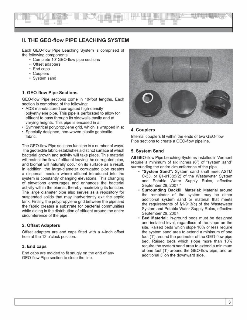
Each GEO-flow Pipe Leaching System is comprised of the following components:
• Complete 10’ GEO-flow pipe sections• Offset adapters• End caps • Couplers• System sand
1. GEO-flow Pipe Sections GEO-flow Pipe sections come in 10-foot lengths. Each section is comprised of the following:• ADS manufactured corrugated high-density
polyethylene pipe. This pipe is perforated to allow for effluent to pass through its sidewalls easily and at varying heights. This pipe is encased in a:
• Symmetrical polypropylene grid, which is wrapped in a:• Specially designed, non-woven plastic geotextile
fabric. The GEO-flow Pipe sections function in a number of ways. The geotextile fabric establishes a distinct surface at which bacterial growth and activity will take place. This material will restrict the flow of effluent leaving the corrugated pipe, and biomat will naturally occur on its surface as a result. In addition, the large-diameter corrugated pipe creates a dispersal medium where effluent introduced into the system is constantly changing elevations. This changing of elevations encourages and enhances the bacterial activity within the biomat, thereby maximizing its function. The large diameter pipe also serves as a repository for suspended solids that may inadvertently exit the septic tank. Finally, the polypropylene grid between the pipe and the fabric creates a substrate for bacterial communities while aiding in the distribution of effluent around the entire circumference of the pipe.
2. Offset Adapters Offset adapters are end caps fitted with a 4-inch offset hole at the 12 o’clock position.
3. End caps End caps are molded to fit snugly on the end of any GEO-flow Pipe section to close the line.
II. THE GEO-flow PIPE LEACHING SYSTEM
4. Couplers Internal couplers fit within the ends of two GEO-flow Pipe sections to create a GEO-flow pipeline.
5. System Sand All GEO-flow Pipe Leaching Systems installed in Vermont require a minimum of six inches (6”) of “system sand” surrounding the entire circumference of the pipe.
• “System Sand”: System sand shall meet ASTM C-33, or §1-913(c)(2) of the Wastewater System and Potable Water Supply Rules, effective September 29, 2007.”
• Surrounding Backfill Material: Material around the remainder of the system may be either additional system sand or material that meets the requirements of §1-913(c) of the Wastewater System and Potable Water Supply Rules, effective September 29, 2007.
• Bed Material: In-ground beds must be designed and installed level, regardless of the slope on the site. Raised beds which slope 10% or less require the system sand area to extend a minimum of one foot (1’) around the perimeter of the GEO-flow pipe bed. Raised beds which slope more than 10% require the system sand area to extend a minimum of one foot (1’) around the GEO-flow pipe, and an additional 3’ on the downward side.
4
III. GEO-FLOW PIPE LEACHING SYSTEM SPECIFICATIONSScopeThis specification describes GEO-flow available in 10-inch (250 mm) inside diameter pipe for use in on-site waste disposal applications in Vermont.
Pipe RequirementsGEO-flow pipe shall meet the requirements of ASTM F667. It shall have a corrugated interior and exterior. There shall be eight 7/16 inch (9.5 mm) holes evenly spaced 45 degrees apart per corrugation continuing the full length of the pipe. The pipe shall be shipped with a pre-installed reinforcing geo-grid fabric and 4 ounce geotextile fabric.
Joint PerformancePipe shall be joined with internal couplers covering at least two full corrugations on each end of the pipe.
Material PropertiesPipe material shall be high density polyethylene conforming to the minimum requirements of cell classification 424410C as defined and described in ASTM D3350.
Geo-Grid FabricMin. Tensile Strength: ASTM D4595; 400 lb/ft.Min. Transmissivity: ASTM D4716; 1 x 10⁻³ m2/sec © 1 and vertical load: 10,000 psf Min. Density: ASTM D1505; 0.940 g/cm3Typical Melt Flow Index: ASTM D1238; 1.0 g/10 min.Min. Carbon Black Content: ASTM D4218; 2 %Min. Thickness: ASTM D5199; 5.0 (200) mm/(mil)Min. Unit Weight: ASTM D3776; 20 oz/sy
4 oz. Geotextile Property SpecificationFiber: PolyesterSubstrate: NoneWeight: 4.0 oz/yd2 +/- 0.04 oz/yd2; FTM NW503 Thickness: 0.065 inch +/- 0.010 inch; FTM NW504 Tensile Warp: 52 lb. min.; FTM NW505Tensile Fill: 68 lb. min.
System Sand: “System sand” shall meet ASTM C-33 (concrete sand) requirements or §1-913(c)(2) of the Wastewater System and Potable Water Supply Rules, effective September 29, 2007.
5
IV. GEO-FLOW PIPE LEACHING SCHEMATIC
V. BASIC DESIGN CONSIDERATIONSGEO-flow Pipe may be used in almost any design configuration imaginable. The system allows great design flexibility in the length, width, slope, and shape of effluent disposal systems.
General ConsiderationsCommon design practices shall apply. These include, but are not limited to:• Product should be designed to be installed on a level
plane;• Product should be designed to run parallel to contours
where possible;• Longer (rather than shorter) product lines are
recommended. Recommended minimum length is 30 feet, and recommended maximum length is 100 feet. In accordance with The Wastewater System and Potable Water Supply Rules, effective September 29, 2007, the maximum length of the GEO-flow pipe rows when installed along the contour of a slope is 100 feet;
• The outlet of the distribution box shall be at least 2 inches above the highest invert any GEO-flow Pipe line in the system.
System Installation Report FormCertified installers must complete a “GEO-flow Pipe Leaching System Installation Report Form” for each system installed, and submit this completed form to ADS. Please see a copy of this form, with instructions, at the back of this manual, labeled “Appendix I”.
Technology Inspection FormCertified designers must provide the system owner with a copy of the “GEO-flow Pipe Leaching System Technology Inspection Form” at the time of system purchase. Please see a copy of this document at the back of this manual, labeled “Appendix II”.
Rules ConflictsIn any instances where these design guidelines are in conflict with the Wastewater System and Potable Water Supply Rules, effective September 29, 2007, the rules shall override these instructions.
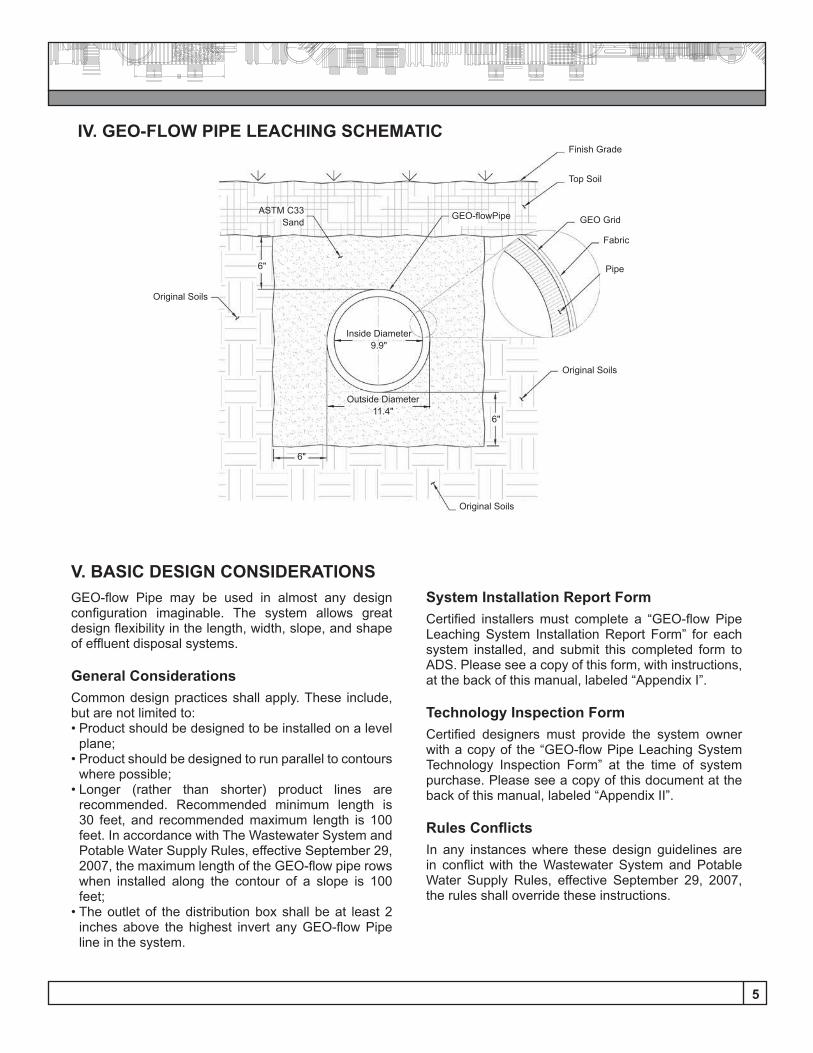
Finish Grade
Top Soil
GEO Grid
Fabric
Pipe
GEO-flowPipe
Original Soils
Original Soils
Original Soils
ASTM C33Sand
6"
6"
6"
Inside Diameter9.9"
Outside Diameter11.4"
6
VI. VERMONT STATE-SPECIFIC CONSIDERATIONSFor in-ground systems on slopes, the bottom of the system sand and pipes must be level; the restrictive layer shall be measured from the deepest part of the bed; and the tops of the pipes must be below original grade.The Wastewater System and Potable Water Supply Rules, effective September 29, 2007, allow the slope of the land for raised beds up to a maximum of 20% on new lots and 30% for certain exempt lots.
Mound WidthThe Rules prohibit use of bed type leachfields that are wider than 10’. However, a GEO-flow Pipe Leaching System design of wider than 10’ may be approved as long as:
(1) The system includes ventilation as required in the current approval;
(2) The linear loading rate is no more than 10 gallons per linear foot per day when the site limitations allow for a prescriptive mound design; or
(3) The linear loading rate is more than 10 gallons per day per linear foot but is supported by a hydrogeologic analysis and the elevation of the GEO-flow piping will comply with the required minimum vertical separation above the induced groundwater mounding.
(4) Sites not meeting the requirements for a prescriptive mound will be evaluated using the performance based design approach, and may, if supported by the hyrogeologic analysis, use linear loading rates exceeding 10 gallons/day/linear foot provided the elevation of the GEO-flow piping will comply with the required minimum vertical separation above the induced groundwater mounding and they are vented as required in the current approval.
(5) The linear loading rate is based on the length of GEO-flow pipe plus a maximum of 2’ of system sand at the ends of the pipe.
VentingAll GEO-Flow Pipe Leaching Systems must include differential venting. The roof vent may be considered the high vent in any system where pumps are not included in the movement of the effluent. In pump-to-gravity distribution systems, a separate high vent must be installed. See detail on Page 16.
Observation PortsApproval of the GEO-flow Pipe System in Vermont requires that each system (or each bed in a system comprised of more than one bed) shall include an observation port. The bottom 18” of a 4-inch PVC pipe must be pre-drilled and wrapped in filter fabric. This pipe must be (1) installed to the base of the system sand, (2) extend beyond final grade, and (3) be capped.
Any and all information in this manual is to be used in con-junction with the Wastewater System and Potable Water Supply Rules, effective September 29, 2007, and all other State and local regulations.
Cover RequirementsThe minimum depth of cover for each GEO-flow Pipe System is ten inches (10”), comprised of six inches (6”) of system sand plus a minimum of four inches (4”) of cover material. Maximum cover is 18 inches.
PipingAll piping that runs between the distribution box and the GEO-flow pipe in the GEO-flow System shall be 4" solid wall PVC.
Installer & Designer CertificationApproval of the GEO-flow Pipe Leaching System in Vermont includes a requirement that all installers and designers of the GEO-flow Pipe Leaching System be trained and certified in its use by a certified ADS/Hancor representative. Until designers and installers are certified, all designs and installations must be approved and/or inspected by a representative of the manufacturer.
Load LimitsEach GEO-flow Pipe Leaching System line shall have a maximum design flow of 500 gallons per day.
Separation DistancesAll minimum vertical and horizontal separation distances as described in the Wastewater System and Potable Water Supply Rules, effective September 29, 2007 must be met with use of the GEO-flow Pipe Leaching System. No reductions in separation distances are allowed.Vertical separation distances shall be measured from the bottom of the GEO-flow pipe. Horizontal setback distances shall be measured from the outside of the system sand.
System SlopeThe Wastewater System and Potable Water Supply Rules, effective September 29, 2007 establish limits on the amount of slope a site may have, depending on several factors. These include, but are not limited to, the date that the lot was created (subdivided) as well as whether the system to be installed is for new construction or will replace an existing system. All requirements of these rules in regards to slope must be met when designing and installing the GEO-flow Pipe Leaching System. In-ground beds must be designed and installed level, regardless of the slope on the site.
7
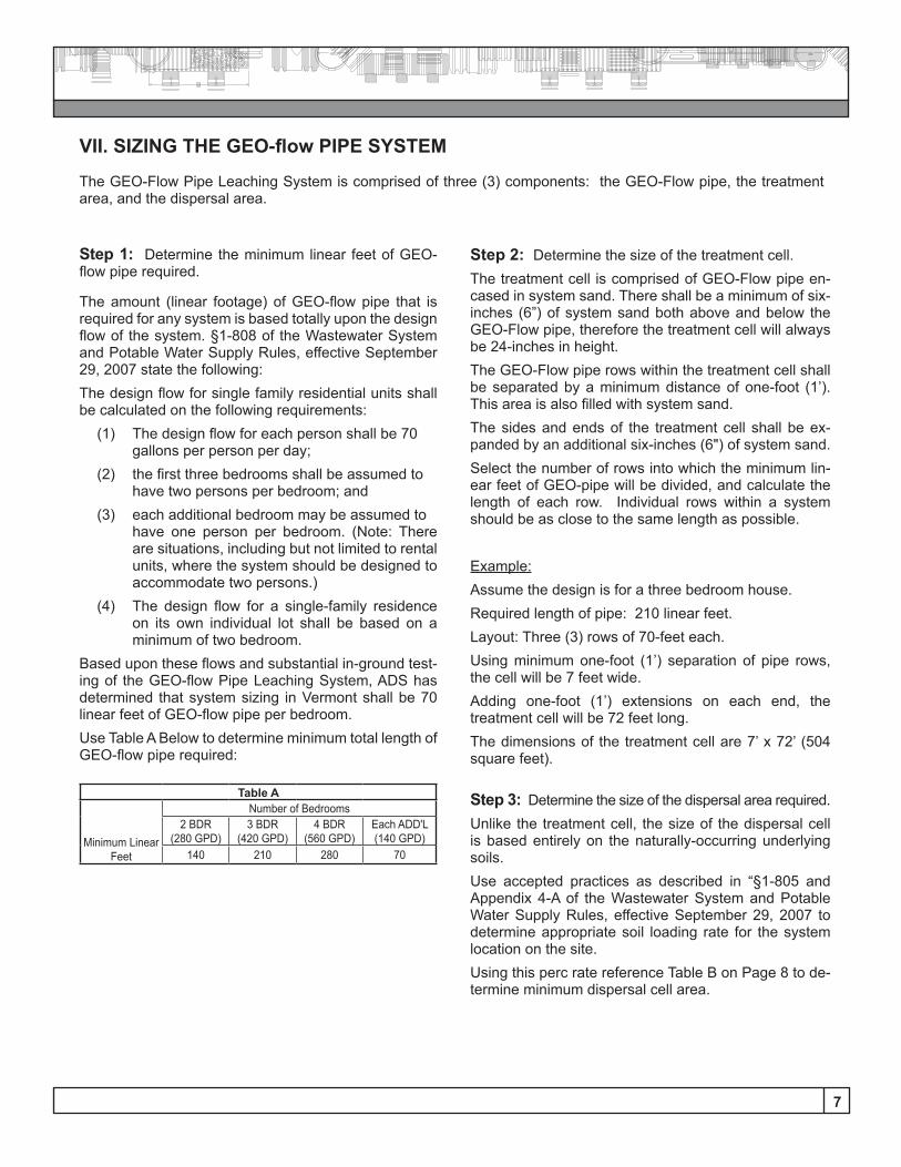
VII. SIZING THE GEO-flow PIPE SYSTEM
The GEO-Flow Pipe Leaching System is comprised of three (3) components: the GEO-Flow pipe, the treatment area, and the dispersal area.
Step 1: Determine the minimum linear feet of GEO-flow pipe required.
The amount (linear footage) of GEO-flow pipe that is required for any system is based totally upon the design flow of the system. §1-808 of the Wastewater System and Potable Water Supply Rules, effective September 29, 2007 state the following:The design flow for single family residential units shall be calculated on the following requirements:
(1) The design flow for each person shall be 70 gallons per person per day;
(2) the first three bedrooms shall be assumed to have two persons per bedroom; and
(3) each additional bedroom may be assumed to have one person per bedroom. (Note: There are situations, including but not limited to rental units, where the system should be designed to accommodate two persons.)
(4) The design flow for a single-family residence on its own individual lot shall be based on a minimum of two bedroom.
Based upon these flows and substantial in-ground test-ing of the GEO-flow Pipe Leaching System, ADS has determined that system sizing in Vermont shall be 70 linear feet of GEO-flow pipe per bedroom.Use Table A Below to determine minimum total length of GEO-flow pipe required:
Step 2: Determine the size of the treatment cell. The treatment cell is comprised of GEO-Flow pipe en-cased in system sand. There shall be a minimum of six-inches (6”) of system sand both above and below the GEO-Flow pipe, therefore the treatment cell will always be 24-inches in height. The GEO-Flow pipe rows within the treatment cell shall be separated by a minimum distance of one-foot (1’). This area is also filled with system sand.The sides and ends of the treatment cell shall be ex-panded by an additional six-inches (6") of system sand.Select the number of rows into which the minimum lin-ear feet of GEO-pipe will be divided, and calculate the length of each row. Individual rows within a system should be as close to the same length as possible.
Example: Assume the design is for a three bedroom house.Required length of pipe: 210 linear feet.Layout: Three (3) rows of 70-feet each.Using minimum one-foot (1’) separation of pipe rows, the cell will be 7 feet wide.Adding one-foot (1’) extensions on each end, the treatment cell will be 72 feet long.The dimensions of the treatment cell are 7’ x 72’ (504 square feet).
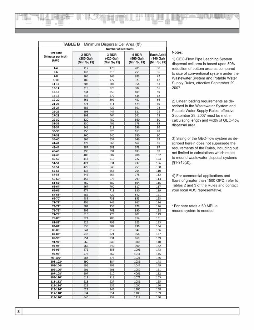
Step 3: Determine the size of the dispersal area required. Unlike the treatment cell, the size of the dispersal cell is based entirely on the naturally-occurring underlying soils.Use accepted practices as described in Ҥ1-805 and Appendix 4-A of the Wastewater System and Potable Water Supply Rules, effective September 29, 2007 to determine appropriate soil loading rate for the system location on the site.Using this perc rate reference Table B on Page 8 to de-termine minimum dispersal cell area.
Table A
Minimum Linear Feet
Number of Bedrooms2 BDR
(280 GPD)3 BDR
(420 GPD)4 BDR
(560 GPD)Each ADD'L(140 GPD)
140 210 280 70
8
Table B Number of Bedrooms
Perc Rate (Minutes per Inch)
(MPI)
2 BDR
(280 Gal)
3 BDR
(420 Gal)
4 BDR 490
Each ADD’L
(70 Gal) 1-‐4 117 175 205 30 5-‐6 143 215 251 36 7-‐8 165 248 289 42 9-‐10 185 277 323 47 11-‐12 203 304 354 51 13-‐14 219 328 382 55 15-‐16 234 350 409 59 17-‐18 248 372 434 62 19-‐20 261 392 457 66 21-‐22 274 411 479 69 23-‐24 286 429 501 72 25-‐26 298 447 521 75 27-‐28 309 464 541 78 29-‐30 320 480 560 80 31-‐32 330 495 578 83 33-‐34 341 511 596 86 35-‐36 350 525 613 88 37-‐38 360 540 630 90 39-‐40 369 554 646 93 41-‐42 379 568 662 95 43-‐44 387 581 678 97 45-‐46 396 594 693 99 47-‐48 405 607 708 102 49-‐50 413 619 722 104 51-‐52 421 631 737 106 53-‐54 429 643 751 108 55-‐56 437 655 764 110 57-‐58 445 667 778 112 59-‐60 452 678 791 113 61-‐62 460 689 804 115 63-‐64 467 700 817 117 65-‐66 474 711 830 119 67-‐68 482 722 842 121 69-‐70 489 733 855 123 71-‐72 495 743 867 124 73-‐74 502 753 879 126 75-‐76 509 763 890 128 77-‐78 516 773 902 129 79-‐80 522 783 914 131 81-‐82 529 793 925 133 83-‐84 535 802 936 134 85-‐86 541 812 947 136 87-‐88 548 821 958 137 89-‐90 554 831 969 139 91-‐92 560 840 980 140 93-‐94 566 849 990 142 95-‐96 572 858 1001 143 97-‐98 578 867 1011 145 99-‐100 584 875 1021 146 101-‐102 590 884 1031 148 103-‐104 595 893 1042 149 105-‐106 601 901 1052 151 107-‐108 607 910 4061 152 109-‐110 612 918 1071 153 111-‐112 618 927 1081 155 113-‐114 623 935 1090 156 115-‐116 629 943 1100 158 117-‐118 634 951 1109 159 119-‐120 640 959 1119 160
Notes:
1) GEO-Flow Pipe Leaching System dispersal cell area is based upon 50% reduction of bottom area as compared to size of conventional system under the Wastewater System and Potable Water Supply Rules, effective September 29, 2007.
2) Linear loading requirements as de-scribed in the Wastewater System and Potable Water Supply Rules, effective September 29, 2007 must be met in calculating length and width of GEO-flow dispersal area.
3) Sizing of the GEO-flow system as de-scribed herein does not supersede the requirements of the Rules, including but not limited to calculations which relate to mound wastewater disposal systems [§1-913(d)].
4) For commercial applications and flows of greater than 1500 GPD, refer to Tables 2 and 3 of the Rules and contact your local ADS representative.
TABLE B Minimum Dispersal Cell Area (ft2)
2 BDR(280 Gal)
(Min Sq Ft)
4 BDR(560 Gal)
(Min Sq Ft)
3 BDR(420 Gal)
(Min Sq Ft)
Each Add'l(140 Gal)
(Min Sq Ft)
*
*
*
*
*
*
*
*
*
*
*
*
*
*
*
*
*
*
*
*
*
*
*
*
*
*
*
*
*
*
*
* For perc rates > 60 MPI, a mound system is needed.
9
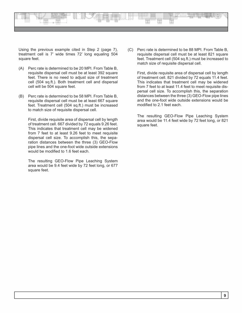
Using the previous example cited in Step 2 (page 7), treatment cell is 7’ wide times 72’ long equaling 504 square feet.
(A) Perc rate is determined to be 20 MPI. From Table B, requisite dispersal cell must be at least 392 square feet. There is no need to adjust size of treatment cell (504 sq.ft.). Both treatment cell and dispersal cell will be 504 square feet.
(B) Perc rate is determined to be 58 MPI. From Table B, requisite dispersal cell must be at least 667 square feet. Treatment cell (504 sq.ft.) must be increased to match size of requisite dispersal cell.
First, divide requisite area of dispersal cell by length of treatment cell. 667 divided by 72 equals 9.26 feet. This indicates that treatment cell may be widened from 7 feet to at least 9.26 feet to meet requisite dispersal cell size. To accomplish this, the sepa-ration distances between the three (3) GEO-Flow pipe lines and the one-foot wide outside extensions would be modified to 1.6 feet each.
The resulting GEO-Flow Pipe Leaching System area would be 9.4 feet wide by 72 feet long, or 677 square feet.
(C) Perc rate is determined to be 88 MPI. From Table B, requisite dispersal cell must be at least 821 square feet. Treatment cell (504 sq.ft.) must be increased to match size of requisite dispersal cell.
First, divide requisite area of dispersal cell by length of treatment cell. 821 divided by 72 equals 11.4 feet. This indicates that treatment cell may be widened from 7 feet to at least 11.4 feet to meet requisite dis-persal cell size. To accomplish this, the separation distances between the three (3) GEO-Flow pipe lines and the one-foot wide outside extensions would be modified to 2.1 feet each.
The resulting GEO-Flow Pipe Leaching System area would be 11.4 feet wide by 72 feet long, or 821 square feet.
10
VIII. INSTALLATION INSTRUCTIONS
GEO-flow Pipe is easy and convenient to install. Its light-weight design makes it easily portable, and ADS fittings make it a simple task to create a system from individual pipe lengths.
General Considerations:Common installation practices shall apply. These in-clude, but are not limited to:• Any smearing of the excavation shall be scarified with
a rake or shovel;• Each line of GEO-flow Pipe should be installed on a
level plane;• Each line of GEO-flow Pipe should be installed parallel
to contours where possible;• GEO-flow Pipe system sand should be installed on the
same day that the disposal area is excavated.
Specific Instructions:All configurations of GEO-flow Pipe require a minimum of 6-inches of specified “system sand” around the en-tire pipe. This approved “system sand” shall meet ASTM Standard C-33 (concrete sand) specification.
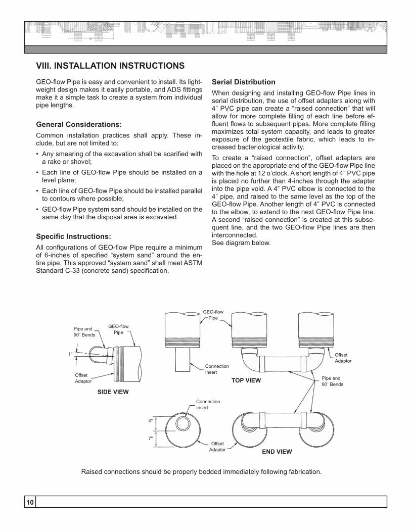
Serial DistributionWhen designing and installing GEO-flow Pipe lines in serial distribution, the use of offset adapters along with 4” PVC pipe can create a “raised connection” that will allow for more complete filling of each line before ef-fluent flows to subsequent pipes. More complete filling maximizes total system capacity, and leads to greater exposure of the geotextile fabric, which leads to in-creased bacteriological activity.To create a “raised connection”, offset adapters are placed on the appropriate end of the GEO-flow Pipe line with the hole at 12 o’clock. A short length of 4” PVC pipe is placed no further than 4-inches through the adapter into the pipe void. A 4” PVC elbow is connected to the 4” pipe, and raised to the same level as the top of the GEO-flow Pipe. Another length of 4” PVC is connected to the elbow, to extend to the next GEO-flow Pipe line. A second “raised connection” is created at this subse-quent line, and the two GEO-flow Pipe lines are then interconnected. See diagram below.
Pipe and 90˚ Bends
Pipe and 90˚ Bends
ConnectionInsert
ConnectionInsert
SIDE VIEW
TOP VIEWOffsetAdaptor
OffsetAdaptor
GEO-flowPipe
GEO-flowPipe
1"
4"
7"
Raised connections should be properly bedded immediately following fabrication.
END VIEW
OffsetAdaptor
11
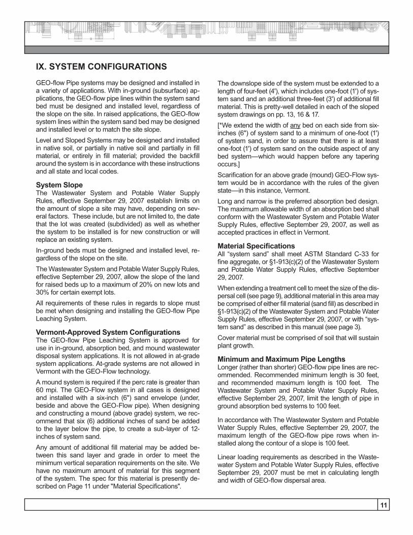
IX. SYSTEM CONFIGURATIONS
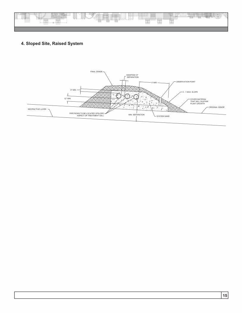
GEO-flow Pipe systems may be designed and installed in a variety of applications. With in-ground (subsurface) ap-plications, the GEO-flow pipe lines within the system sand bed must be designed and installed level, regardless of the slope on the site. In raised applications, the GEO-flow system lines within the system sand bed may be designed and installed level or to match the site slope.Level and Sloped Systems may be designed and installed in native soil, or partially in native soil and partially in fill material, or entirely in fill material; provided the backfill around the system is in accordance with these instructions and all state and local codes.
System SlopeThe Wastewater System and Potable Water Supply Rules, effective September 29, 2007 establish limits on the amount of slope a site may have, depending on sev-eral factors. These include, but are not limited to, the date that the lot was created (subdivided) as well as whether the system to be installed is for new construction or will replace an existing system. In-ground beds must be designed and installed level, re-gardless of the slope on the site.The Wastewater System and Potable Water Supply Rules, effective September 29, 2007, allow the slope of the land for raised beds up to a maximum of 20% on new lots and 30% for certain exempt lots.All requirements of these rules in regards to slope must be met when designing and installing the GEO-flow Pipe Leaching System.
Vermont-Approved System ConfigurationsThe GEO-flow Pipe Leaching System is approved for use in in-ground, absorption bed, and mound wastewater disposal system applications. It is not allowed in at-grade system applications. At-grade systems are not allowed in Vermont with the GEO-Flow technology.A mound system is required if the perc rate is greater than 60 mpi. The GEO-Flow system in all cases is designed and installed with a six-inch (6") sand envelope (under, beside and above the GEO-Flow pipe). When designing and constructing a mound (above grade) system, we rec-ommend that six (6) additional inches of sand be added to the layer below the pipe, to create a sub-layer of 12- inches of system sand.Any amount of additional fill material may be added be-tween this sand layer and grade in order to meet the minimum vertical separation requirements on the site. We have no maximum amount of material for this segment of the system. The spec for this material is presently de-scribed on Page 11 under "Material Specifications".
The downslope side of the system must be extended to a length of four-feet (4'), which includes one-foot (1') of sys-tem sand and an additional three-feet (3') of additional fill material. This is pretty-well detailed in each of the sloped system drawings on pp. 13, 16 & 17.[*We extend the width of any bed on each side from six-inches (6") of system sand to a minimum of one-foot (1') of system sand, in order to assure that there is at least one-foot (1') of system sand on the outside aspect of any bed system—which would happen before any tapering occurs.]Scarification for an above grade (mound) GEO-Flow sys-tem would be in accordance with the rules of the given state—in this instance, Vermont.Long and narrow is the preferred absorption bed design. The maximum allowable width of an absorption bed shall conform with the Wastewater System and Potable Water Supply Rules, effective September 29, 2007, as well as accepted practices in effect in Vermont.
Material SpecificationsAll “system sand” shall meet ASTM Standard C-33 for fine aggregate, or §1-913(c)(2) of the Wastewater System and Potable Water Supply Rules, effective September 29, 2007.When extending a treatment cell to meet the size of the dis-persal cell (see page 9), additional material in this area may be comprised of either fill material (sand fill) as described in §1-913(c)(2) of the Wastewater System and Potable Water Supply Rules, effective September 29, 2007, or with “sys-tem sand” as described in this manual (see page 3).Cover material must be comprised of soil that will sustain plant growth.
Minimum and Maximum Pipe LengthsLonger (rather than shorter) GEO-flow pipe lines are rec-ommended. Recommended minimum length is 30 feet, and recommended maximum length is 100 feet. The Wastewater System and Potable Water Supply Rules, effective September 29, 2007, limit the length of pipe in ground absorption bed systems to 100 feet.
In accordance with The Wastewater System and Potable Water Supply Rules, effective September 29, 2007, the maximum length of the GEO-flow pipe rows when in-stalled along the contour of a slope is 100 feet.
Linear loading requirements as described in the Waste-water System and Potable Water Supply Rules, effective September 29, 2007 must be met in calculating length and width of GEO-flow dispersal area.
12
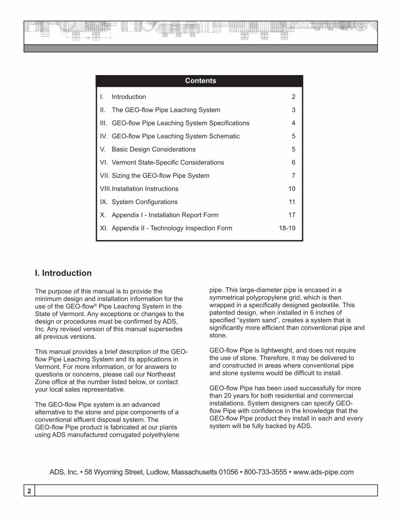
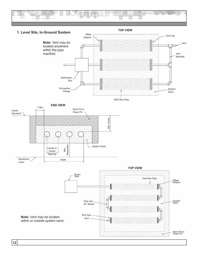
1. Level Site, In-Ground System
END VIEW1' Min.
GradeElevation
RestrictiveLayer
Center toCenter
Spacing
Width
Sand Fill orClean Fill
Min
. Cov
er
Min
. S
epar
atio
n
System Sand
SepticTank
Pipe and 90˚ Bends
End CapVent
Sand Fill or Clean Fill
SystemSand
OffsetAdaptor
Geo-flow Pipe
TOP VIEW
Note: Vent may be located within or outside system sand.
OffsetAdaptor
End Cap
Vent
VentManifold
SystemSand
DistributionBox
ConnectionFittings
GEO-flow Pipe
Note: Vent may be located anywhere within the pipe manifold.
TOP VIEW
13
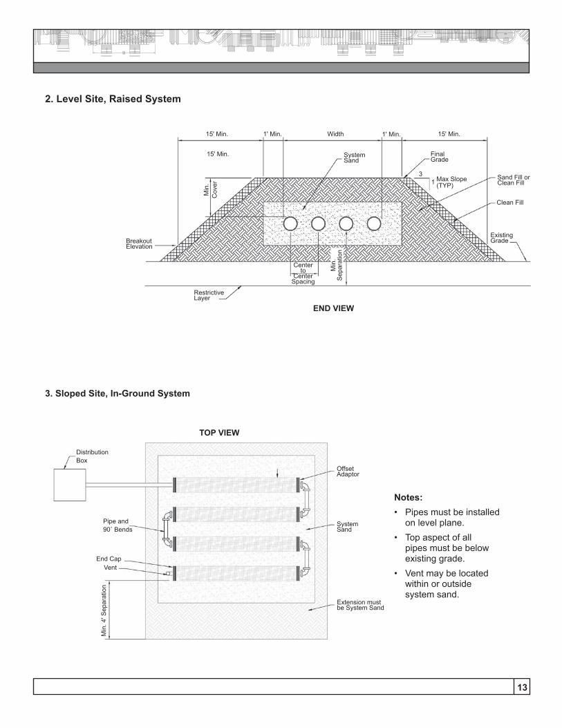
15' Min. Width 15' Min.1' Min.
Centerto
CenterSpacing
ExistingGrade
Clean Fill
Sand Fill or Clean Fill
Restrictive Layer
Final Grade
System Sand
15' Min.
Min
.C
over
Min
.S
epar
atio
n
1' Min.
BreakoutElevation
31 Max Slope
(TYP)
END VIEW
DistributionBox
Pipe and 90˚ Bends
End CapVent
Min
. 4' S
epar
atio
n
Extension must be System Sand
SystemSand
OffsetAdaptor
TOP VIEW
Notes: • Pipes must be installed
on level plane.• Top aspect of all
pipes must be below existing grade.
• Vent may be located within or outside system sand.
2. Level Site, Raised System
3. Sloped Site, In-Ground System
Vent
14
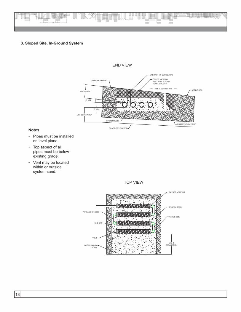
3. Sloped Site, In-Ground System
Notes: • Pipes must be installed
on level plane.• Top aspect of all
pipes must be below existing grade.
• Vent may be located within or outside system sand.
15
4. Sloped Site, Raised System

16
3. Combination SystemsGEO-flow Pipe systems may be designed and installed with the use of a combination of serial and parallel distribution. In-ground, raised, level, and sloped compo-nents may all be combined to create a specific system.
4. Non-conventional System ConfigurationsNon-conventional system configurations are just that — configurations that are not of common length, width and/or shape.In general, GEO-flow Pipe systems should include individual lines that are at least 30-feet long and no lon-ger than 100-feet in total length. However, with proper distribution, both shorter and longer systems may be designed and installed.GEO-flow Pipe lines in a common system should be straight. However, site considerations intermittently call for changes in direction of the effluent disposal line. The GEO-flow Pipe system can accommodate such chal-lenges, allowing for design and installation of curves, angled, and even nearly circular disposal lines.Contact your local sales representative if you feel a non-conventional GEO-flow Pipe configuration could solve your site challenge.
5. Pressure Distribution The GEO-flow Pipe system cannot directly accom-modate pressure distribution. Effluent may be pumped from a septic tank or pump station to a GEO-flow Pipe disposal field, but the following conditions must be strictly met in order to assure proper function:A. Effluent cannot be pumped directly into the GEO-
flow Pipe line(s). Effluent shall be pumped to a dis-tribution box, and from that point gravity distributed into the GEO-flow Pipe system.
B. Design dosing of pumped effluent into the distribu-tion box prior to gravity distribution into the GEO-flow Pipe system shall occur at a rate of no greater than 20 gallons per minute (GPM).
C. Differential venting is required on all GEO-flow Pipe systems which receive effluent from a pump. Differential venting is accomplished with the use of two vents – one extending from the distribution box and another at the other end of the line. The vent extending from the distribution box must extend a minimum of 10’ higher than the elevation of the other. (See vent schematic below).
6. Venting RequirementsAll GEO-flow Pipe Leaching Systems must be vented.
17
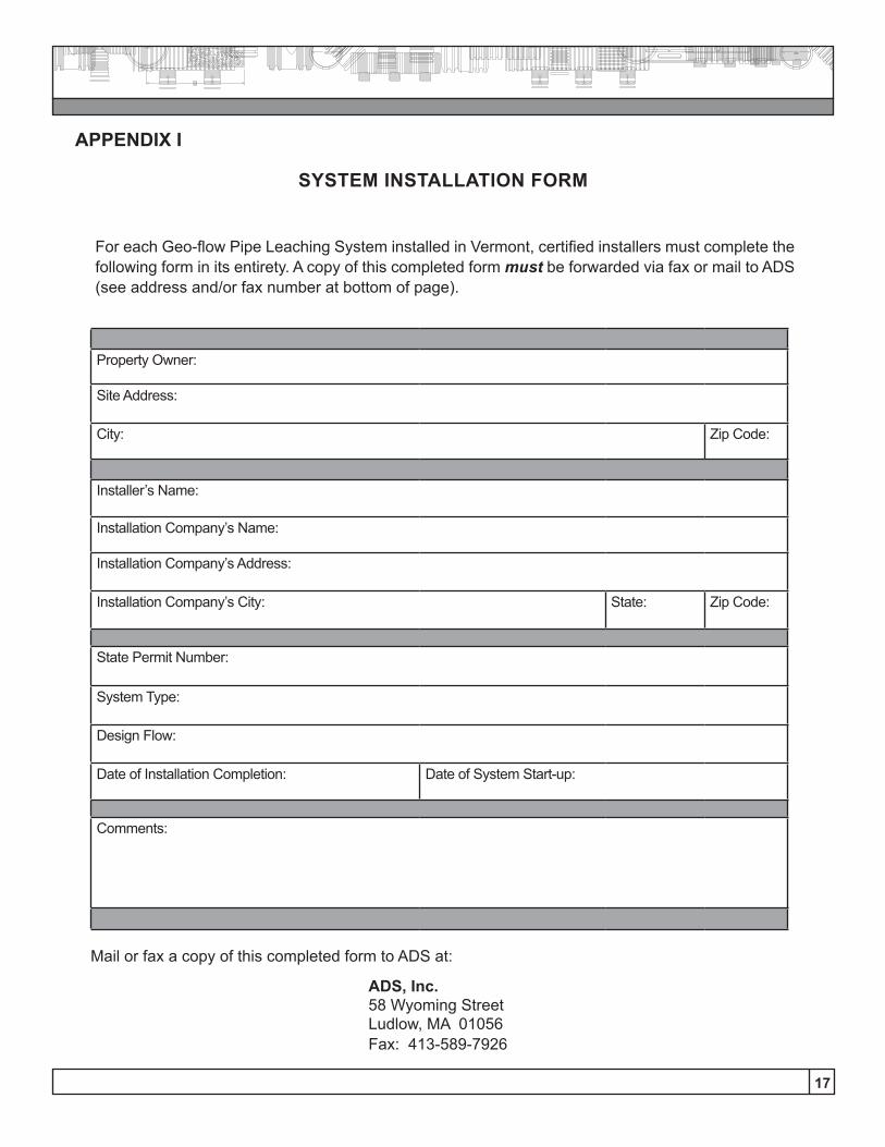
For each Geo-flow Pipe Leaching System installed in Vermont, certified installers must complete the following form in its entirety. A copy of this completed form must be forwarded via fax or mail to ADS (see address and/or fax number at bottom of page).
APPENDIX I
SYSTEM INSTALLATION FORM
ADS, Inc.58 Wyoming StreetLudlow, MA 01056Fax: 413-589-7926
Mail or fax a copy of this completed form to ADS at:
Property Owner:
Site Address:
City: Zip Code:
Installer’s Name:
Installation Company’s Name:
Installation Company’s Address:
Installation Company’s City: State: Zip Code:
State Permit Number:
System Type:
Design Flow:
Date of Installation Completion: Date of System Start-up:
Comments:
18
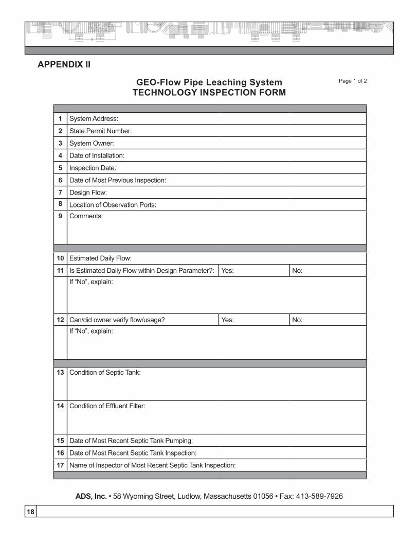
APPENDIX II
GEO-Flow Pipe Leaching SystemTECHNOLOGY INSPECTION FORM
Page 1 of 2
1 System Address:
2 State Permit Number:
3 System Owner:
4 Date of Installation:
5 Inspection Date:
6 Date of Most Previous Inspection:
7 Design Flow:8 Location of Observation Ports:9 Comments:
10 Estimated Daily Flow:
11 Is Estimated Daily Flow within Design Parameter?: Yes: No:If “No”, explain:
12 Can/did owner verify flow/usage? Yes: No:If “No”, explain:
13 Condition of Septic Tank:
14 Condition of Effluent Filter:
15 Date of Most Recent Septic Tank Pumping:
16 Date of Most Recent Septic Tank Inspection:
17 Name of Inspector of Most Recent Septic Tank Inspection:
ADS, Inc. • 58 Wyoming Street, Ludlow, Massachusetts 01056 • Fax: 413-589-7926
19
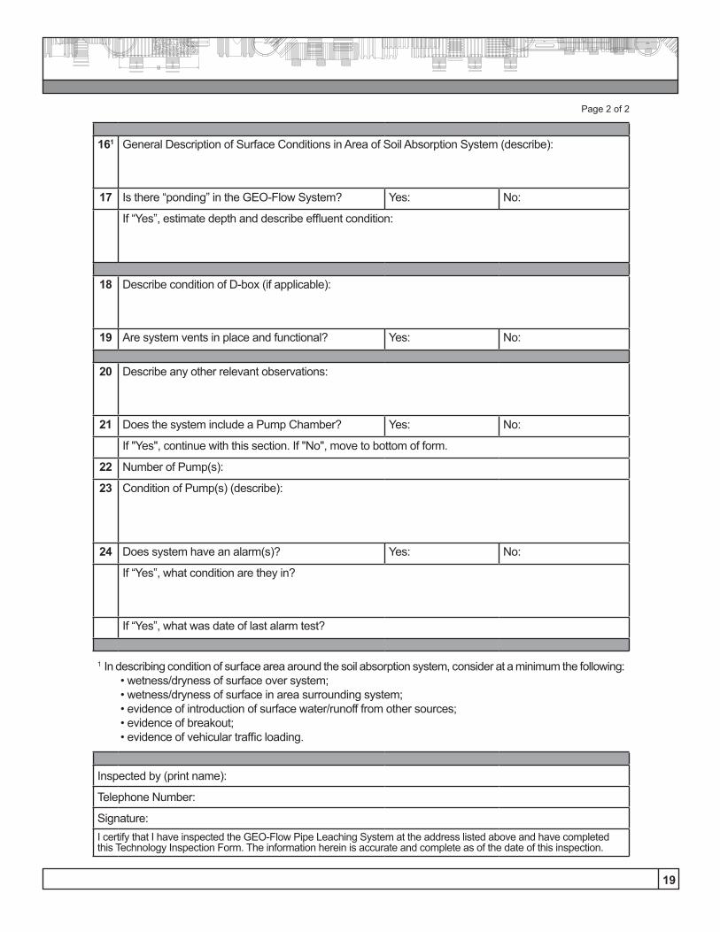
Page 2 of 2
161 General Description of Surface Conditions in Area of Soil Absorption System (describe):
17 Is there “ponding” in the GEO-Flow System? Yes: No:
If “Yes”, estimate depth and describe effluent condition:
18 Describe condition of D-box (if applicable):
19 Are system vents in place and functional? Yes: No:
20 Describe any other relevant observations:
21 Does the system include a Pump Chamber? Yes: No:
If "Yes", continue with this section. If "No", move to bottom of form.
22 Number of Pump(s):
23 Condition of Pump(s) (describe):
24 Does system have an alarm(s)? Yes: No:
If “Yes”, what condition are they in?
If “Yes”, what was date of last alarm test?
1 In describing condition of surface area around the soil absorption system, consider at a minimum the following: • wetness/dryness of surface over system; • wetness/dryness of surface in area surrounding system; • evidence of introduction of surface water/runoff from other sources; • evidence of breakout; • evidence of vehicular traffic loading.
Inspected by (print name):
Telephone Number:
Signature:I certify that I have inspected the GEO-Flow Pipe Leaching System at the address listed above and have completed this Technology Inspection Form. The information herein is accurate and complete as of the date of this inspection.

1-800-821-6710 www.ads-pipe.com
888-FOR PIPE (367-7473)www.hancor.com
Innovation in product, process and technology. That’s ADS and Hancor.
Advanced Drainage Systems, the ADS logo, the green stripe, “The Most Advanced Name in Drainage Systems” and GEO-flow® are registered trademarks of Advanced Drainage Systems, Inc. Hancor is a registered trademark of Hancor, Inc. ADS “Terms and Conditions of Sale” are available on the ADS website, www.ads-pipe.com. © 2013 Advanced Drainage Systems, Inc. INS10847 /0313
Revised March 2013