Embed Size (px)
Citation preview
PUBLIC HEALTH ORDINANCE FOR
McHENRY COUNTY ILLINOIS
McHENRY COUNTY DEPARTMENT OF HEALTH
ARTICLE IV
WASTEWATER AND SEWAGE TREATMENT AND DISPOSAL
2
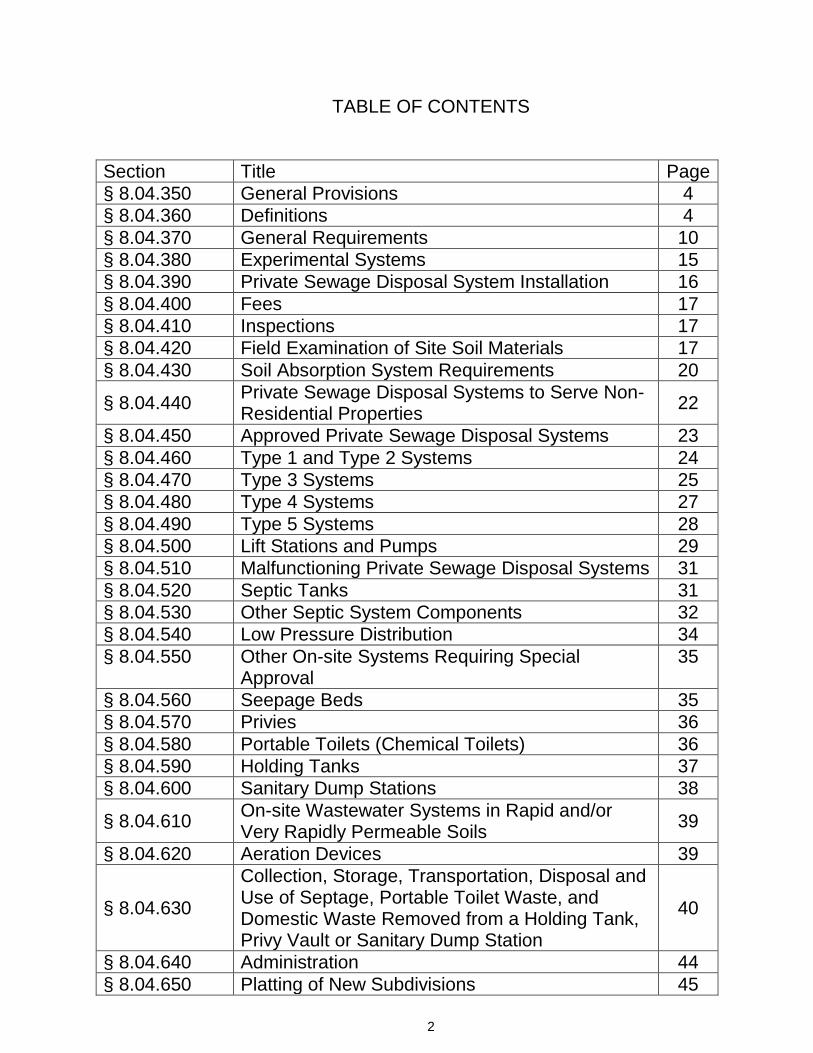
TABLE OF CONTENTS
Section Title Page
§ 8.04.350 General Provisions 4
§ 8.04.360 Definitions 4
§ 8.04.370 General Requirements 10
§ 8.04.380 Experimental Systems 15
§ 8.04.390 Private Sewage Disposal System Installation 16
§ 8.04.400 Fees 17
§ 8.04.410 Inspections 17
§ 8.04.420 Field Examination of Site Soil Materials 17
§ 8.04.430 Soil Absorption System Requirements 20
§ 8.04.440 Private Sewage Disposal Systems to Serve Non-Residential Properties
22
§ 8.04.450 Approved Private Sewage Disposal Systems 23
§ 8.04.460 Type 1 and Type 2 Systems 24
§ 8.04.470 Type 3 Systems 25
§ 8.04.480 Type 4 Systems 27
§ 8.04.490 Type 5 Systems 28
§ 8.04.500 Lift Stations and Pumps 29
§ 8.04.510 Malfunctioning Private Sewage Disposal Systems 31
§ 8.04.520 Septic Tanks 31
§ 8.04.530 Other Septic System Components 32
§ 8.04.540 Low Pressure Distribution 34
§ 8.04.550 Other On-site Systems Requiring Special Approval
35
§ 8.04.560 Seepage Beds 35
§ 8.04.570 Privies 36
§ 8.04.580 Portable Toilets (Chemical Toilets) 36
§ 8.04.590 Holding Tanks 37
§ 8.04.600 Sanitary Dump Stations 38
§ 8.04.610 On-site Wastewater Systems in Rapid and/or Very Rapidly Permeable Soils
39
§ 8.04.620 Aeration Devices 39
§ 8.04.630
Collection, Storage, Transportation, Disposal and Use of Septage, Portable Toilet Waste, and Domestic Waste Removed from a Holding Tank, Privy Vault or Sanitary Dump Station
40
§ 8.04.640 Administration 44
§ 8.04.650 Platting of New Subdivisions 45
3
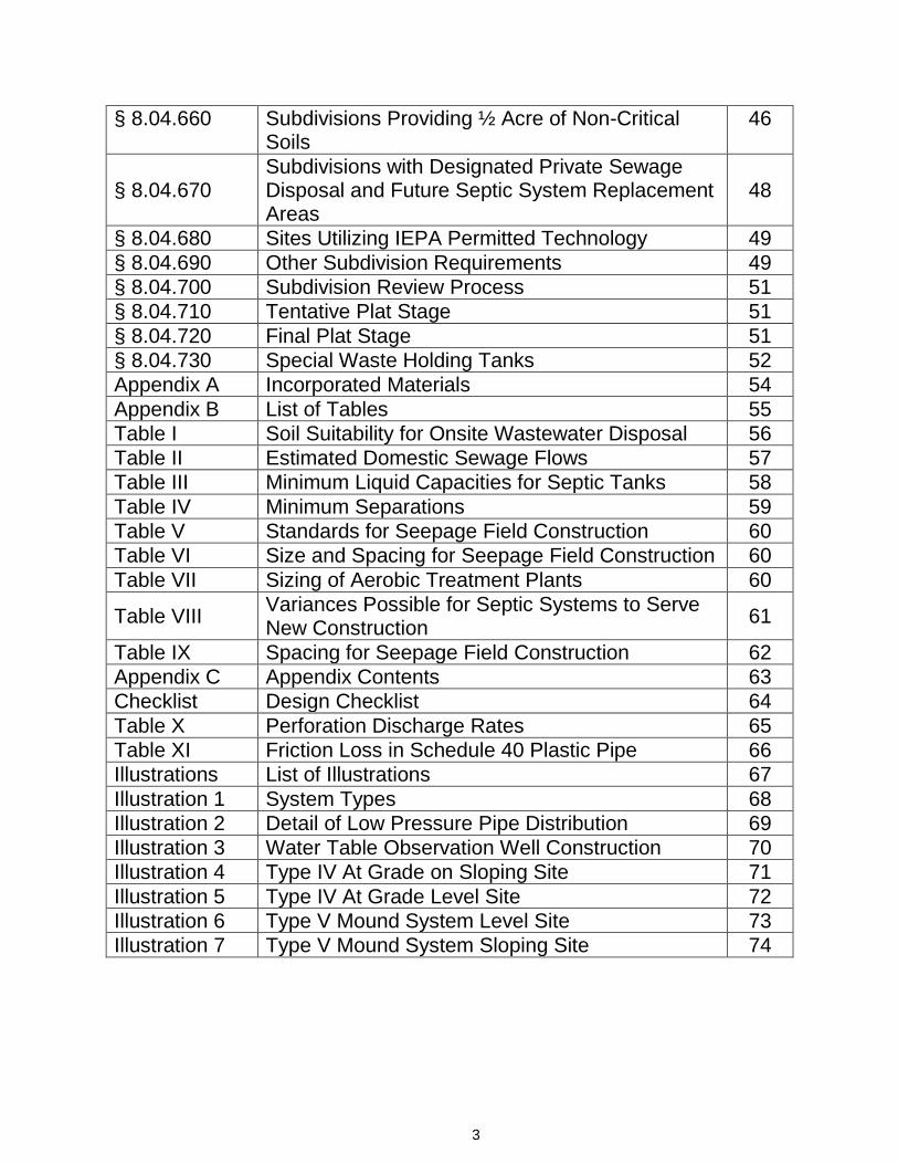
§ 8.04.660 Subdivisions Providing ½ Acre of Non-Critical Soils
46
§ 8.04.670 Subdivisions with Designated Private Sewage Disposal and Future Septic System Replacement Areas
48
§ 8.04.680 Sites Utilizing IEPA Permitted Technology 49
§ 8.04.690 Other Subdivision Requirements 49
§ 8.04.700 Subdivision Review Process 51
§ 8.04.710 Tentative Plat Stage 51
§ 8.04.720 Final Plat Stage 51
§ 8.04.730 Special Waste Holding Tanks 52
Appendix A Incorporated Materials 54
Appendix B List of Tables 55
Table I Soil Suitability for Onsite Wastewater Disposal 56
Table II Estimated Domestic Sewage Flows 57
Table III Minimum Liquid Capacities for Septic Tanks 58
Table IV Minimum Separations 59
Table V Standards for Seepage Field Construction 60
Table VI Size and Spacing for Seepage Field Construction 60
Table VII Sizing of Aerobic Treatment Plants 60
Table VIII Variances Possible for Septic Systems to Serve New Construction
61
Table IX Spacing for Seepage Field Construction 62
Appendix C Appendix Contents 63
Checklist Design Checklist 64
Table X Perforation Discharge Rates 65
Table XI Friction Loss in Schedule 40 Plastic Pipe 66
Illustrations List of Illustrations 67
Illustration 1 System Types 68
Illustration 2 Detail of Low Pressure Pipe Distribution 69
Illustration 3 Water Table Observation Well Construction 70
Illustration 4 Type IV At Grade on Sloping Site 71
Illustration 5 Type IV At Grade Level Site 72
Illustration 6 Type V Mound System Level Site 73
Illustration 7 Type V Mound System Sloping Site 74
4
PUBLIC HEALTH ORDINANCE FOR
McHENRY COUNTY ILLINOIS
McHENRY COUNTY DEPARTMENT OF HEALTH
ARTICLE IV – WASTEWATER AND SEWAGE TREATMENT AND DISPOSAL
§ 8.04.350 GENERAL PROVISIONS A. Title This Ordinance shall be known and cited as "The McHenry County Private Sewage Treatment and
Disposal Ordinance" (hereinafter the "Ordinance"). B. Purpose It is hereby declared that there exists within McHenry County, Illinois, the need for a system of
controls over the site review, design, construction, materials, installation, operation and maintenance of private sewage disposal systems, and the disposal of residues therefrom; and the disposal of wastewater from structures served by private sewage disposal systems. Therefore, the purpose of this Ordinance is to protect, promote and preserve the public health, safety, and general welfare by providing those controls.
C. General Rule Construction of private sewage disposal systems shall not be permitted on property where a
sanitary sewer is available and accessible. If a sanitary sewer is not available and accessible, every residence, business, building or enterprise shall have its own private sewage disposal system in conformance with the provisions set forth in this Ordinance.
D. Applicability After the effective date of adoption of this Ordinance, all private sewage disposal systems as
defined herein shall only be constructed or modified in accordance with the provisions of this Ordinance.
§ 8.04.360 DEFINITIONS A. General For the purposes of this Ordinance, certain terms and phrases shall be deemed to have the
meaning described to them in this Section. Words in the singular number include the plural, those in the plural number include the singular. Words in the present tense include the past and future tenses, and the future tense includes the present tense. The masculine gender shall include the feminine and neuter genders. The word "shall" is mandatory, while the word "may" is permissive.
B. TERMS DEFINED "ACCESSIBLE" as it pertains to a sanitary sewer means that the sewer is located in a public right-of-way or easement contiguous to the property. Further provided that the sewer or a service stub can be reached without excessive tunneling or boring under a roadway, building, or flowing stream, and that the sewer or service stub is not further than 300 feet from the residential property line or 1000 feet from the property line of the non-residential building to be served. It is not the intent for an individual to subsidize the extension costs of a sanitary sewer system; therefore, only an individual connection with an individual line will be required. “ACCESSORY STRUCTURE” means any structure with a roof that is not attached to the dwelling. "AEROBIC TREATMENT UNIT" means a sewage treatment unit, which incorporates a means of introducing air into sewage so as to provide aerobic biochemical stabilization during a detention period.
5
"ARCPACS” means A Federation of Certifying Boards of Agriculture, Biology, Earth and Environmental Sciences. "APPLICANT" means the property owner as defined herein or his or its authorized agent. "APPROVED" as it pertains to an on-site disposal system means constructed and installed in compliance with technical standards and requirements of this Ordinance. "APPROVED" installation does not imply or ensure that a system will perform satisfactorily. "AVAILABLE” means that the property owner has a right to connect to the sanitary sewer, or the municipality is allowing the construction. "BEDROOM" for the purpose of establishing the rate of flow for domestic sewage, means any room containing a closet, which is suitable to regular use as a bedroom and which shares a common hallway with or is adjoining at least a 3/4 bath. "BIOCHEMICAL OXYGEN DEMAND" (BOD) is an empirical test that measures the oxygen required for the biochemical degradation of organic material and the oxygen used to oxidize inorganic material such as sulfides and ferrous iron. “CHEMICAL TOILET” means a toilet structure equipped with a watertight impervious container, which receives waste, discharged through a hopper, seat, urinal or similar device and into which container may be placed disinfecting or deodorizing chemicals. For the purposes of this Ordinance, chemical toilet and portable toilet shall have the same meaning. "COUNTY" means the County of McHenry, Illinois. "CRITICAL SOILS" are those soil materials that have been disturbed and/or have natural limitations including seasonal or actual water tables, permeabilities slower than moderately slow, or bedrock, extensive enough to require alternative systems or are perhaps so limited as to preclude the practicality of on-site domestic wastewater treatment. "DEPARTMENT” means the McHenry County Department of Health. “DISCHARGE RATE” means the volume of effluent discharged from a low-pressure distribution system expressed as gallons per minute and applied as a rate either per perforation, per line, or per system. “DISTAL END PRESSURE” means a measure of system pressure in a low-pressure distribution system made at the end of a lateral distribution pipe opposite the force main connection, and expressed as feet of pressure head. "DOMESTIC SEWAGE” means wastewater derived principally from plumbing fixture drains in dwellings, business or office buildings, institutions, food establishments, and similar facilities. It shall not include industrial or commercial processing waste. "EFFECTIVE SIZE” means the size of screen opening where 90 percent by weight of a sample of sand is retained on the screen and 10 percent passes through the screen. This size is usually expressed in millimeters. "EFFECTIVE SOIL DEPTH" means the depth of slightly or moderately limited soil material lying above a restrictive soil layer such as clay, hardpan, or bedrock.
6
"EFFLUENT” means the outflow from a tank or other treatment unit. “EFFLUENT FILTER” means a device installed at the outflow of a septic tank, which screens solids ordinarily suspended in solution. “EXISTING SQUARE FOOTAGE” means the habitable square footage of the structure in place as of the adoption date of this Ordinance. "FLOOD ELEVATION, BASE” means the regulatory elevations established by the methods adopted by the McHenry County Stormwater Management Ordinance and which establish the limit of intrusion or retainment of a “100 year flood event” or that flood having a one percent probability of occurring in any given year. "FLOOD HAZARD AREA" means any area composed of floodplain land. "FLOODPLAIN" means that land typically adjacent to a body of water with ground surface elevations at or below the base flood elevation or the 100-year frequency flood elevation. Floodplains may also include detached Special Flood Hazard Areas, ponding areas, etc. The floodplain is also known as the Special Flood Hazard Area. “GRAVELLESS SEEPAGE SYSTEM” means the use of approved perforated 8 inch or 10 inch diameter, filter wrapped, plastic pipe, or chamber systems as approved by the Illinois Department of Public Health, in lieu of 4 inch pipe and gravel, in subsurface fields and serial distribution systems. “HABITABLE” means any room or enclosed floor space with electric and heat intended to be used for living, sleeping, or eating purposes including bathrooms, hallways, and closets but not including attics, garages or unfinished basements. "HEALTH AUTHORITY" means the Administrator of the McHenry County Department of Health, or his designated agent. “HOT TUB” means an artificial container of water with a liquid capacity greater than 100 gallons and designed with a mechanical air injection system and/or recirculating device. These devices may filter and/or disinfect the water for reuse and are not intended to be drained between uses. "HUMAN WASTE" means the normal excretory waste of the human body. "INDIVIDUAL SEWAGE TREATMENT SYSTEM” means a sewage treatment system or part thereof serving a dwelling or other establishment or group thereof which utilizes subsurface soil treatment and disposal. “LICENSED ENVIRONMENTAL HEALTH PRACTITIONER” means a person who is licensed as an environmental health practitioner per 225 ILCS 37/17. “LIMITING LAYER” means a horizon or condition in the soil profile or underlying strata which includes:
a. A seasonal high water table, whether perched or regional, determined by direct observation of the water table or indicated by soil mottling where common mottles comprise at least 2% to 20% of the soil in a progressive downward direction in the soil, whichever is more restrictive.
b. Masses of loose rock fragments, including gravel, with insufficient fine soil to fill the voids
between the fragments.
7
c. Rock formation, other stratum or soil condition, which is so slowly permeable that it effectively
limits downward passage of effluent. "LIQUID CAPACITY" means the internal volume of a tank below the invert of the outlet line. “LOT” means a lot of record which is a part of a subdivision, the plat of which has been duly authorized and recorded in the Office of the Recorder of Deeds of McHenry County, Illinois, and which is intended to be used as a unit by one (1) principal building and its accessory buildings. “NRCS” means Natural Resource Conservation Service. “NSF” means NSF International, an independent testing laboratory. "NON-CRITICAL SOILS" are those undisturbed soil materials that can support a conventional private sewage disposal system, where at least the lower portion (six inches minimum) of the soil absorption part of the system can be installed in original, un-compacted (undisturbed) soil. “NON-RESIDENTIAL PROPERTY” means any property that is not used for a single family home. “ONE FOR ONE REPLACEMENT” means a replacement structure of the same number of bedrooms (for commercial properties the same estimated domestic sewage flows and type of operation) and the same square footage of habitable space as of the adoption date of this Ordinance or indicated on the most recently issued construction permit. “ORIGINAL SOIL SURFACE” means the natural or native soil surface exclusive of fill material. "PARCEL" means an area of land described by metes and bounds or by division, making reference to the original government survey. For purposes of this ordinance, a parcel is not a LOT. "PERMEABILITY" means the ease with which liquids move through a soil. “PERSON" means any individual, group of individuals, association, trust, partnership, corporation, person doing business under an assumed name, or any other entity, government and/or private. "PLANNING & DEVELOPMENT DEPARTMENT" means the McHenry County Department of Planning and Development. “POROUS EARTH FILL” means mineral soil, not organic soil such as peat or muck. The organic matter content shall be less than 6%. Soil texture shall include silt loam, loam, or sandy clay loam, or sandy loam of a consistent USDA texture. Clay content shall range from 10% to 27%, and sand content shall range from 30% to 80%. The content of gravel (>2mm) shall be less than 5% by volume. Clods shall be less than 10% by volume and less than four (4) inches in size. The material shall be free of extraneous, non-soil material such as construction or vegetative debris. “PORTABLE TOILET“ see CHEMICAL TOILET. “POTENTIAL SECONDARY SOURCE” means any unit at a facility or a site not currently subject to a removal or remedial action, other than a potential primary source, which:
8
a. Is utilized for the landfilling, land treating, or surface impounding of waste that is generated on the site or at other sites, owned, controlled or operated by the same person, other than livestock and landscape waste, and construction and demolition debris: or
b. Stores or accumulates at any time more than 25,000 but not more than 75,000 pounds above
ground, or more than 2,500 but not more than 7,500 pounds below ground, of any hazardous substances: or
c. Stores or accumulates at any time more than 25,000 gallons above ground, or more than 500
gallons below ground, of petroleum, including crude oil or any fraction thereof which is not otherwise specifically listed or designated as a hazardous substance: or
d. Stores or accumulates pesticides, fertilizers, or road oils for purposes of commercial application
or for distribution to retail sales outlets; or stores or accumulates at any time more than 50,000 pounds of any de-icing agent: or
e. Is utilized for handling livestock waste or for treating domestic wastewaters other than private
sewage disposal systems as defined in the “Private Sewage Disposal Licensing Act” (Section 3.3355 of the Environmental Protection Act
"PRIVATE SEWAGE DISPOSAL SYSTEM" means any sewage handling or treatment facility receiving domestic sewage for disposal on the property where it was generated, or on property where the same owner has legal access, and having no ground surface discharge there or on any parcel, lot or property. Private Sewage Disposal System shall also mean septic system. “PRIVATE SEWAGE DISPOSAL SYSTEM IN ACCEPTABLE CONDITION” means a septic tank or aeration device that does not have actual or indications of effluent levels over the outlet pipe and an absorption area (mound, field, trench, chamber, etc) that does not have actual or indications of sewage on the ground surface, or ponding in the trench or seepage bed above the stone level, gravelless pipe or chamber. "PRIVATE SEWAGE DISPOSAL INSTALLATION CONTRACTOR" means any person operating with a valid license from the Illinois Department of Public Health for the constructing, installing, repairing, modifying or maintaining private sewage disposal systems. “PRIVATE SEWAGE DISPOSAL SYSTEM CLASSIFIED AS A CLASS V INJECTION WELL” means any private sewage disposal system considered to be a Class V injection well under the 35 Illinois Administrative Code Part 704. "PRIVATE SEWAGE DISPOSAL SYSTEM PUMPING CONTRACTOR” means any person who cleans or pumps waste from a private sewage disposal system or hauls or disposes of wastes removed therefrom. "PRIVATE SEWAGE DISPOSAL SYSTEM PUMPING CONTRACTOR PERMIT” means a permit issued by the Department to a private sewage disposal system pumping contractor, allowing the cleaning or pumping of private sewage disposal systems in McHenry County or hauling and disposing of domestic septage in McHenry County. "PRIVY" means a structure allowing for the disposal of human excreta into a sealed vault in the ground. "PROPERTY" means a parcel of land or lot for which legal title has been recorded. "PROPERTY OWNER" means the person in whose name legal title to property is recorded.
9
“RESIDENTIAL PROPERTY” means a single family home intended for occupation as living quarters that is not used to conduct any business that generates wastewater or domestic sewage. “SANITARY SEWER” means a treatment facility permitted by the Illinois Environmental Protection Agency. “SEASONAL OPERATION” means an operation that operates at a single location for not more than a total of five (5) months per calendar year. "SEPTAGE" means the liquid and solid material removed from domestic septic tanks or other approved pretreatment systems, and specifically excluding wastes from portable toilets, holding tanks, grease traps and sewage treatment plant sludge material. “SEPTIC RESTRICTED AREAS” means those areas not considered suitable for septic system installation due to critical soils, excessive slopes, required setback distances, etc. “SEWAGE” means all of the domestic wastewater and all wastewater other than domestic derived from plumbing fixture drains in a dwelling, business or office building, food establishments, and similar facilities. It shall include industrial and commercial processing waste. "SOIL BORING" means an observation pit, dug by hand or backhoe, or an undisturbed soil core taken intact and undisturbed by a probe. “SOIL CLASSIFIER” means the following: A certified soil classifier of the Illinois Soil Classifiers Association (ISCA) or a certified soil classifier with the Federation of Certifying Boards of Agriculture, Biology, Earth and Environmental Sciences (ARCPACS). "SOIL CHARACTERISTICS, LIMITING" means those soil characteristics which preclude the installation of a Type 1 – Type 5 System (See § 8.04.460 - § 8.04.490 and Illustration 1) including but not limited to fill material, bedrock, soils with permeability of less than .2 inches per hour, actual or seasonal high groundwater tables, etc. “SOIL MOTTLING” means low chroma equal to or less than 2 and a value of 4 or more (Munsell-Color Chart.) "SOIL SATURATION" means the state when all the pores in a soil are filled with water. "SOIL TEXTURAL CLASSIFICATION" means where soil particle sizes or textures are specified in this Ordinance, they refer to soil textural classification in the USDA/NRCS Soil Survey Manual. “SPECIAL FLOOD HAZARD AREA” means any area subject to flooding from a river, creek, intermittent stream, ditch or any other identified channel or ponding and shown on a Flood Hazard Boundary Map or Flood Insurance Rate Map as Zone A, AO, A1-30, AE, A99, AH, VO, V30, VE, V, M, E, D, or X. “SPECIAL WASTE HOLDING TANK” means a watertight tank, which receives the wastewater discharge from fixtures or drains, which receive waste products such as automotive grease, oils, solvents and chemicals that are not allowed to discharge into a private sewage disposal system. “SUITABLE SOIL” means soils where the actual or seasonal high groundwater or other limiting layer is a minimum of thirty (30) inches from the natural soil surface.
10
“TEMPORARY EVENT” means an event that operates at a fixed location for a period of time of not more than fourteen (14) consecutive days in conjunction with a single event or celebration. “UNIFORMITY COEFFICIENT” means a number obtained by dividing that size of sand in millimeters of which 60% by weight is smaller, by that size of sand in millimeters of which 10% by weight is smaller. “WASTEWATER” means all wastewater other than domestic sewage derived from plumbing fixture drains in a dwelling, business or office building, food establishments, and similar facilities. It shall include industrial and commercial processing waste. “WATER TABLE” means the upper limit of the portion of the soil which is completely saturated with water. The seasonal high water table is the highest level to which the soil is saturated, as may be indicated by mottling (soil color patterns).
§ 8.04.370 GENERAL REQUIREMENTS
A. Owner’s Responsibility Property owners of all buildings or places where people live, work, or assemble, shall provide for the sanitary disposal of all human waste and domestic sewage. Human waste and domestic sewage from each such building or place not disposed of by discharging into a sanitary sewer, shall be disposed of in compliance with this Ordinance.
B. Building Occupancy No person shall occupy or permit occupancy of any building or structure not in
compliance with Subsection A above.
C. Rate of Flow for Domestic Sewage Each unit of the private sewage disposal system shall be designed to treat the volume of domestic sewage discharged to it. The volume of sewage flow shall be determined from § 8.04.430 A-D and Tables I and II (See Appendix B).
D. Type of Waste A private sewage disposal system shall be designed to receive all domestic sewage from
the buildings served. No cooling water, groundwater, discharge from roof drains, discharge from footing tile drains, swimming pool wastewater, or other clear water discharges shall be directed to the private sewage disposal system. Waste products, such as automotive grease, oils, solvents, and chemicals, shall not be discharged to a private sewage disposal system. These waste products shall be handled according to the rules for disposal of oil, gas and grease promulgated under the Environmental Protection Act, or according to 35 Ill. Adm. Code Subtitle G, or shall be taken to an oil and gas reclamation center. Drains or fixtures receiving any wastewater other than domestic sewage shall be discharged to a special waste holding tank and not to a private sewage disposal system; (See§ 8.04.730).
E. Water Softener Backwash Backwash water from a water softener shall discharge to one of the
following:
1. A septic tank followed by a seepage field.
2. A separate building drain, in accordance with the Illinois Plumbing Code, that will discharge to a subsurface seepage system, provided that seepage field is designed to accommodate the flow from this device on a daily basis. The separate building drain from this device may bypass the septic tank in front of the seepage field. A septic tank is not required in front of a seepage field receiving flow from this device.
F. Hot Tub Wastewater Domestic sewage generated by a hot tub or other similar device shall be
11
discharged to one of the following:
1. A separate subsurface seepage system, provided the seepage field is designed to accommodate the liquid capacity of the hot tub on a daily basis. A septic tank is not required in front of a seepage field receiving flow from this device.
2. The septic field serving the domestic sewage flow, provided the seepage field is increased in size to
accommodate the additional flow from the hot tub on a daily basis. This drainage shall be piped around the septic tank and directly into the seepage field.
G. Clear Water Discharges Clear water wastes may be discharged directly to storm sewers, natural
drainage areas, or to the ground surface without additional treatment provided that it does not conflict with any State or local drainage law. Such drainage shall not result in nuisance conditions which create an offensive odor, or which produce a stagnant wet area, or which produce an environment for the breeding of insects.
H. Swimming Pools Wastewater from swimming pools may not be discharged to a private sewage disposal
system receiving domestic sewage. Wash or backwash water from swimming pool sand filters may be discharged to natural drainage areas, storm sewers, or to the ground surface provided that it does not conflict with any State or local drainage law. Diatomaceous earth filter wash or backwash water may be discharged to one of the above after treatment consisting of one of the following:
1. Passing the earth filter wash or backwash water through a separation tank designed for removal of
the diatomaceous earth and suspended solids.
2. Settling the earth filter wash or backwash water in a tank, which is capable of holding the volume of one backwash. One backwash is defined as the amount of water generated from the backwash of the filters for a period of 2 minutes for diatomaceous earth filters, at the required backwash flow rate. The tank shall be dewatered after settling and prior to subsequent backwashes. Settled sludge shall be periodically removed to prevent flushing of solids during backwashing.
3. A separate private sewage disposal system designed and constructed in accordance with the
applicable Sections of this Ordinance.
I. Individual Service The use of a private sewage disposal system to serve more than one property is prohibited except where a common property is provided, under joint ownership of the users, or where the system is under public jurisdiction or managed by a district established for the maintenance of such systems.
J. Water and Sewer Line Separation The following criteria shall govern the separation of water supply
lines and sewer lines:
1. Horizontal Separation Sewers shall be installed at least 10 feet horizontally from any existing or proposed water line. When local conditions prevent a lateral separation of 10 feet, a sewer may be laid closer than 10 feet to a water line provided that the elevation of the crown of the sewer is at least 18 inches below the invert of the water line, and the sewer line is Schedule 40 or heavier material with watertight joints.
2. Crossings Where sewer lines must cross water lines, the sewer line shall be laid at such an elevation
that the crown of the sewer line is at least 18 inches below the invert of the water line. This vertical
12
separation shall be maintained for that portion of the sewer line located within 10 feet horizontally of any water line it crosses. When sewer lines must cross above water lines, the sewer lines shall be Schedule 40 or heavier material with watertight joints.
K. Permit Required No private sewage disposal system shall be constructed, replaced, modified, altered,
extended or repaired until a permit has been issued by the Health Authority. Applications for permits shall be in writing on forms provided by the Department and shall be signed by the owner or his authorized agent. Said permit to construct replace, modify, alter, extend or repair shall be valid for a period of two (2) years from date of issuance. If construction or repair is not commenced and significant progress not achieved within said period, the permit shall expire unless an extension is approved by the Health Authority. The permit can be renewed for a period of 6 (six) months for 1/2 of the prevailing permit fee, provided all the conditions of the original submittal remain valid. Where a septic system is required for a structure, no building permit shall be issued without the prior or simultaneous issuance of a septic permit. No private sewage disposal system shall be put into use until it has been approved by the Health Authority.
L. No Permit Required No permit is required when the nature of a repair is so minor as to not influence
the size or substantially alter the function of the system (i.e., broken vent pipe, settling of distribution box, etc.). Replacement of seepage stone, gravelless seepage system or perforated pipe in the seepage area of the septic system requires a permit for repair or replacement.
M. New Construction For the purposes of this Ordinance, new construction is considered a new structure,
or when 50% or more of the habitable square footage of an existing structure is added, or when additional bedrooms are added to an existing structure, or when there will be additional estimated domestic sewage flows in a non-residential structure, or when an addition to an existing structure will not meet the setback requirements in Table IV (See Appendix B.) In all such cases, the septic system shall either be in compliance with Article IV requirements or new septic plans approved for the new construction prior to the issuance of the building permit.
N. Exemptions
1. Structure Destroyed or Unsound In the event a structure is destroyed by 50% or more of the existing habitable square footage by fire, wind, or water, or 50% or more of the existing habitable square footage is determined by a Licensed Architect or Structural Engineer to be unsound; it shall be eligible for a replacement structure if the property cannot support a private sewage disposal system meeting Article IV new construction requirements. A replacement residential structure must be of the same number of bedrooms and can be up to 50% larger in habitable square footage than the original structure. A replacement non-residential structure must have the same estimated domestic sewage flow (See Table II, Appendix B) of the original structure. A Licensed Architect or Structural Engineer shall issue a certificate as to the condition of the structure to the Health Authority; or
2. Additions Greater than 50%
a. When additions greater than 50% of the habitable square footage of the existing structure and no new bedrooms are added; the private sewage disposal system must be in acceptable condition, as confirmed by an evaluation provided by an Illinois Licensed Engineer or Licensed Environmental Health Practitioner; or
b. New private sewage disposal system plans must have been approved by the
Department for the structure.
13
O. Other Restrictions The above exemptions do not supersede any local zoning or building restrictions (i.e.
minimum size of structure and structure setbacks).
P. Application for Permit Application for permits shall be in writing, shall be signed by the applicant, and shall include the following:
1. Name and address of the applicant, and date and signature of owner, owner’s agent or private
sewage disposal system installation contractor.
2. The location and legal description of the property and permanent property index number (PPI) on which construction, repair, replacement, modification, alteration or extension is proposed, and size (dimensions) and area of lot or building site. A survey of the property shall be provided.
3. For single-family residences – the number of bedrooms. For non-residential structures, the estimated domestic sewage flows from Table II (see Appendix B).
4. A description including sizes of each unit of the proposed sewage treatment or disposal systems, and all calculations that entered into the sizing of the system(s).
5. Evidence to demonstrate that a public sewer, is not available and accessible, to the property line of the building for which a septic system is proposed. For non-residential structures, available shall mean within 1000 feet of the property line.
6. Soil findings from on-site soil evaluation shall be provided as required in § 8.04.420 A through § 8.04.420 E. This shall be accompanied by a drawing (plan) depicting the exact location (including dimensions) of soil borings on the property.
7. Four (4) copies, 17” x 22”, of the engineered design of the system drawn to scale (one inch equals 10’, 20’, or 30’) and fully dimensioned, and specifications to fully describe the system. It shall show:
a. Lot boundaries and property dimensions; b. Proper orientation of directions relative to the property in question; c. Location of any underground utilities; d. Locations of any easements and/or septic restricted areas; e. Locations and sizes of all drains, wells, stormwater drywells, buildings, driveways, parking areas,
sidewalks, decks, patios, and designated subsurface seepage and future replacement subsurface seepage areas, whether existing or proposed on the subject and adjacent properties;
f. The private sewage disposal system to be constructed, repaired, replaced, modified, altered or
extended; g. Locations of soil borings; h. A clearly described bench mark which will be maintained throughout the construction period;
14
i. Any trees to remain within 10 feet of any part of the private sewage disposal system; j. Existing and proposed topography in one foot contours; k. Building foundation elevation; l. A detailed plan of proposed tank(s) and effluent disposal system (both top and side view); m. All critical elevations, (e.g. top of foundation, invert of plumbing stub-out, inlet and outlet of
tank, inlet of distribution box, seepage tile line, bottom of trench, etc.) referenced to the benchmark;
n. Septic system design calculations (sizing, LPP calculations, etc.); o. Building location with all lateral distances indicated, including distance from building served to
system, from system to well(s) (list type of wells), adjoining systems, lot lines, lake, stream or other water-course;
p. Detail of lift station including tank size, dose, reserve capacity, pump specifications, forcemain protection and high water alarm;
q. Trench detail showing a cross sectional view of the subsurface seepage area; and r. A statement, which specifies whether or not the septic system is designed to accommodate a
hot tub or garbage grinder/garbage disposal; and s. Location of special waste holding tank on subject and neighboring properties.
Q. All septic system designs shall be drawn by or under the direct supervision of a Registered Professional
Engineer (as that term is defined in 225 ILCS 325) or Licensed Private Sewage Disposal Installation Contractor (as defined) or a Licensed Environmental Health Practitioner (as defined). All septic system designs shall be based on soil characterization information determined by a soil classifier, meeting the criteria in § 8.04.420 A through § 8.04.420 E. All copies of application forms and plans shall bear signature and license expiration date of the individual who performed or supervised the specific work. Any person who designs a septic system shall be responsible for the accuracy of all information required by Subsection P above on that design.
R. Permit Granted When, upon review of the application, the proposed design meets the requirements of
the Ordinance, the Health Authority shall grant written approval of said application.
S. Permit Denial When, upon review of the application, the Health Authority finds the information incomplete, inaccurate, or does not meet the requirements of this Ordinance, he/she shall deny approval of said application.
T. Appeal of Review or Permit Denial Any permit applicant may appeal the review or denial of any permit
application through the provisions set forth in Article I of the Public Health Ordinance.
U. Variances When circumstances exist which make impractical full compliance with the requirements of this Ordinance, as listed in this paragraph, an applicant may request that the Health Authority grant a variance. Such request shall be made in writing and shall accompany the system plans. Any data which
15
supports the request shall be submitted. The Health Authority may grant the request for variance, provided said variance does not conflict with the stated purpose of this Ordinance. (See Table VIII in Appendix B for general guidelines.)
V. Variances for Existing Structures When variations are granted for separation distances to water wells;
separation from bottom of trench to limiting layers; location of the system in the flood hazard area or for sizing of the seepage area at less than required based upon Table I in Appendix B for replacement septic systems for existing structures, these restrictions must be recorded as covenant(s) running with the land with the McHenry County Recorder of Deeds.
W. Maintenance of Private Sewage Disposal Systems Private sewage disposal systems installed after
January 1, 2014 shall be maintained in compliance with Section 905.20q of the Illinois Private Sewage Disposal Code.
§ 8.04.380 EXPERIMENTAL SYSTEMS
A. Experimental Systems – General The Health Authority may issue an experimental use permit for a private sewage disposal system or component which is new or innovative, and is not described in this Ordinance. Written approval is also required from the Illinois Department of Public Health for such system.
B. Experimental Permit Applications Applications for experimental use permit shall be submitted in
accordance with, and shall conform to, the permit requirements set forth in § 8.04.370K as well as the following additional criteria:
1. Experimental Permit Details The application shall specify the type of proposed system or
component and be accompanied by plans, specifications per applicable sections and engineering data to support the system’s ability to comply with the system design requirements under §
8.04.420 and§ 8.04.430.
2. Experimental Replacement System The experimental system shall be replaced with an approved system if the experimental system fails to perform in accordance with any of the sections of this Ordinance or with criteria established as a condition to approval of the system.
3. Experimental Permit Review Process Upon receipt of the information required in § 8.04.430, the
Department will review the experimental system to assess the system’s ability to conform to requirements of this Ordinance. All experimental permit applications shall be reviewed by the technical review committee, who shall make a recommendation as to its acceptability to the Department (See§ 8.04.550). If approved, the Department will issue an “Experimental Use Permit” for the system and file a Certificate of Notice with the Office of the McHenry County Recorder, which shall indicate that the property’s private sewage disposal system is an experimental system under evaluation by the Department. The Certificate of Notice shall remain on the title through the evaluation period. The performance of the experimental system shall be evaluated by the Department for a two-year period. The experimental system shall be in use throughout the evaluation period. At the end of the two-year evaluation period, the Department shall make a determination as to the system’s acceptability. The system shall be unacceptable if sewage erupts from the ground, or if the system fails to meet the criteria established as condition to approval of the system. If acceptable, the experimental system shall become an approved private sewage disposal system for that specific site. If unacceptable, the experimental system shall not be approved and shall be replaced with an approved system. The Department shall notify the applicant
16
in writing of its final determination. If acceptable, the Department shall record a release of the Certificate of Notice. If unacceptable, the Certificate of Notice shall remain on the title until an approved system has been installed.
§ 8.04.390 PRIVATE SEWAGE DISPOSAL SYSTEM INSTALLATION
A. Licensed Private Sewage Disposal Installation Contractor No installation shall be made without a written permit from the Health Authority issued either to a Licensed Private Sewage Disposal Installation Contractor, or to the owner or lessee of the lot. All septic system installations, repairs, alterations, extensions and modifications must be performed by a Licensed Private Sewage Disposal Installation Contractor. In order to operate in McHenry County, a contractor must be licensed by the Illinois Department of Public Health (IDPH) pursuant to 225 ILCS 225/4, of the Illinois Compiled Statutes.
B. Installer Responsibilities It is the responsibility of the licensed private sewage disposal installation
contractor to install the septic system per the approved septic design, and to notify the Health Authority of any discrepancies between the installation site and the approved septic design. Failure to install the septic system per the approved septic design or to notify the Health Authority of such discrepancies constitutes a violation of this Ordinance by the Private Sewage Disposal Installation Contractor.
C. Protection of Area After the permit has been issued for a proposed private sewage disposal system,
the area in which the system is to be installed shall be identified and shall not be cut, excavated, filled, or otherwise altered in any way except as specified in the approved plans. The permit holder shall protect the area from construction traffic and all other activities, which might compact the soil.
D. Owner Responsibility It shall be the responsibility of the property owner to protect all components and
reserve areas of his private sewage disposal system from damage due to installation of utilities. A minimum five-foot horizontal separation between all sewage system components and utility conduit shall be maintained. Where local conditions prevent a five (5) foot separation, a forcemain, manifold or building sewer may be laid closer than five (5) feet from a utility conduit, provided that the forcemain, manifold or building sewer is sleeved within a larger diameter Schedule 40 or heavier solid pipe for any portion less than five (5) feet.
E. Free from Encroachment The area to be used for a private sewage disposal system shall be selected and
maintained so that it is free from encroachment by driveways, decks, accessory buildings, swimming pools, parking areas, buried lawn sprinkling systems, underground utility services, patios, slabs, additions to the original structure or any other structure which limits free access to the system for maintenance, servicing or proper operation. A permanent barrier is required to prevent trafficking of the septic system when the system abuts a parking lot or driveway.
F. Decks/Patios Decks shall be allowed over septic tanks, aeration devices and lift stations provided that
access is maintained at each access point for maintenance and repair, and that the deck does not encroach upon the soil absorption or designated expansion areas. For decks greater than or equal to five (5) feet above the ground surface, the space below the deck will be considered the access. Patios shall be allowed over septic tanks, aeration devices and lift stations provided that free access to all of the portals is provided.
G. Construction Traffic On sites where septic system installation will be difficult (i.e. on small lots), the
Health Authority will require that the location for material storage and a pathway for construction traffic be specified on the septic design.
17
H. Tree Removal Any removal of trees greater than or equal to six (6) inches in diameter shall be by cutting near the surface. Stumps may be removed by grinding or cutting, but shall not be uprooted.
§ 8.04.400 FEES
A. Fee Schedule No permit shall be issued until the appropriate permit fee, as set forth in the Public Health Fee Ordinance, has been paid. All fees double if work is started without a permit or registration.
B. Miscellaneous Sewage Program Fees The fee schedule is set forth in the Public Health Fee Ordinance
for miscellaneous services.
§ 8.04.410 INSPECTIONS
A. Department Access The Department shall have access to any property seeking permit approval or to investigate a malfunctioning private sewage disposal system to determine satisfactory compliance with the provisions set forth in the Ordinance. Access shall be deemed essential for, but not necessarily limited to, the following:
1. Performing soil investigations and witnessing soil borings.
2. On-site layout review.
3. Inspecting any stage of installation of the system.
4. Final inspection following completion of the system installation, prior to covering.
5. Inspection of a malfunctioning private sewage disposal system.
B. Notice of Installation The owner or contractor shall give 24 hours advance notice to the Department before beginning installation, modification, alteration or extension of any component of the private sewage disposal system.
C. Order to Uncover If any person constructs, installs, repairs, or modifies a private sewage disposal
system without complying with any of the requirements of this Ordinance and backfills any portion of the system or covers any portion of the system with earth, gravel, or any other material which will prevent the Department or local authority from viewing the system to determine compliance with this Ordinance, the property owner and/or private sewage disposal installation contractor shall uncover the backfilled or covered portions of the system for inspection by the Department, upon request of the Department.
§ 8.04.420 FIELD EXAMINATION OF SITE SOIL MATERIALS
A. Soil Investigation Determination of soil characteristics on sites proposed for development with private sewage disposal systems shall be based on soil boring data collected by a soil classifier. Each property owner or applicant shall contract with a soil classifier, to identify soil characteristics and classifications for the purpose of reporting soil suitability potential for soil absorption systems. The Department shall utilize NRCS for periodic quality control sessions with all classifiers available for the performance of on-site soil evaluations, and for needed soils expertise to the Department in connection with the needs of this Ordinance.
B. Boring Criteria There shall be a minimum of three (3) suitable borings per soil absorption system site.
18
More soil borings may be necessary for accurate and appropriate evaluation of a site where there is some concern about the consistency of the soil materials. One of the borings shall be made at the lowest portion of the proposed absorption field area. Such borings shall extend at least five (5) feet below the natural ground surface or greater if needed, based on the proposed system design. The proposed subsurface seepage system shall be located within the area of the soil borings. Soil borings shall be valid for one year after the test date, after which time an update is required by the soil classifier.
C. Soil Pits Observation and determination of soil characteristics may also be determined from a pit dug by
a backhoe or other excavating equipment. Soil pits (backhoe excavation) shall be required in cases where ground is frozen, where the soil materials are considerably varied in texture, where there has been filling or proposed cutting of soils, or where trenches are proposed deeper than normally considered, etc. Such soil pits shall be prepared at the perimeter of the expected soil absorption area to minimize damage to natural soil distribution network that may be caused by settling after installation of the system. Soil pits shall be at least two (2) feet wide and five (5) feet deep.
D. Site Characteristics Site characteristics to be described include zones of seasonal and permanent water
saturation, depth to bedrock, USDA/NRCS soil texture, USDA/NRCS soil structural features of note, slope, compaction and depth, soil coloration, depth of soil mottling, permeability range, and other limiting soil characteristics that may reduce permeability.
E. County Review The County reserves the right to review site soil characteristics with assistance from a
certified NRCS soil classifier. In the process, the County reserves the right to witness any such tests. If conflicting soils investigation is provided about a given site, a certified NRCS soil classifier will be requested to provide professional information.
F. Site Evaluation On-site sewage disposal systems may be utilized where lots or parcels are in compliance
with the applicable County Ordinances in effect on the date of permit application and all of the criteria for site consideration in Table I (See Appendix B) are satisfied.
G. Minimum Depth to Limiting Layer In no case shall the depth to any limiting layer be less than 12 inches
from the natural soil surface (see next paragraph). Providing this can be met, the separation below the bottom surface of the soil absorption system and the top of any limiting layer (i.e. seasonal groundwater, impermeable strata, bedrock, etc.) shall be as follows:
1. Rapidly Permeable Soils Soils having rapid to very rapid permeability (> 6.0 in./hr.) shall have at
least 4 feet of separation (or as allowed in Table I).
2. Moderately Rapid Soils Soils having a permeability rate between 2 in./hr. and 6.0 in./hr. shall have at least 3 feet of separation (or as allowed in Table I).
3. Moderate Soils Soils having a permeability rate slower than 2 in./hr. shall have at least 2 feet of
separation (or as allowed in Table I).
4. Creviced Limestone Formations A subsurface seepage system shall not be constructed in an area where there is less than 4 feet of soil between the lowest point in a subsurface seepage system and the top of a creviced limestone formation. In areas where creviced limestone is known to occur, a soil boring to a depth of at least 4 feet below the bottom of the subsurface seepage system shall be made to verify that creviced limestone is not present.
H. Setbacks All setbacks and horizontal distances in Table IV shall be satisfied.
19
I. Surface Water Overflow The site of the installation shall not be subject to saturation from surface water
overflow from natural or artificial drainage of ground surfaces, driveways, roads or roof drains.
J. Flood Hazard Area The land elevation at the site of the proposed system installation shall not be subject to flooding, (i.e. shall not be within the 100 year flood hazard area as defined by the base flood elevation of the closest stream or body of water). Such elevation shall be provided in USGS/MSL (United States Geological Survey Mean Sea Level) datum.
K. Future Replacement Area – Non Residential Properties In all cases where non-residential properties
are proposed for development, an area for a full-size replacement system shall be provided. The area shall be suitable for septic installation as confirmed by onsite soil investigation and designated for future septic system replacement. This replacement area shall be kept free of development, traffic or soil modification on all properties.
L. Slope Restrictions Private sewage disposal systems shall not be permitted on slopes exceeding 25 %
(reference Table I on slope limitation).
M. Septic Suitability on New Land Parcels Parcels of less than 10 acres created on or after September 1, 1990 will be required to demonstrate (via on-site soils evaluation procedures) one-half acre of contiguous, non-critical soils within the boundaries of the parcel(s), or designated subsurface seepage and future replacement subsurface seepage areas in compliance with § 8.04.650 Platting of New Subdivisions, before a permit will be issued for installation of a septic system. The septic system must be installed within an area of non-critical soils, or the designated subsurface seepage area. This is to ensure that all new parcels being created are being developed in a manner that is consistent with§
8.04.650. On all lots within a subdivision recorded after the date of February 1, 2003, the 1/2 acre of contiguous, non-critical soils, or the designated subsurface seepage area on each lot shall not be altered or modified until a septic system permit has been issued.
N. Water Table Monitoring Wells Water table monitoring may be utilized when the property owner feels
that the results of the soil test conducted do not accurately reflect present day seasonal water tables. The following requirements will be used when a request is made to use observed water tables in lieu of soil borings. Please Note: Monitoring in itself does not ensure approval to install a soil absorption system. Once monitoring is completed, a request for a variance from the use of soil mottling as an indicator of high groundwater or seasonal saturation must be made in writing to the Public Health Administrator.
1. Installation Approval Written approval will be given by the Department after all the required data
listed below has been received and reviewed. Construction of monitoring wells shall not start until this approval has been received.
2. Soil Boring Logs Detailed soil boring logs of the area to be monitored are to be submitted with the
proposal.
3. Number of Monitoring Wells No less than two (2) monitoring wells shall be present in the area of the proposed private sewage disposal system. One (1) of the monitoring wells shall be located in the lowest portion of the proposed subsurface seepage area. Monitoring wells shall be present to accurately portray seasonal groundwater conditions.
4. Location and Design The location and design of the monitoring wells shall be drawn to scale on a
20
plot sheet. The design shall be based upon Illustration 3 (Appendix C.), or other design as approved by the Department.
5. Monitoring Data Format The monitoring data shall be recorded by a licensed professional engineer
or soil classifier.
6. Monitoring Period The wells will be required to be monitored for a period of one (1) year with precipitation amounts of plus or minus 15% of the average. Rainfall during the Spring season (March 21 to June 21) must be equal to or greater than the normal amount for that period. The precipitation amounts will be taken from the closest reporting weather station.
7. Monitoring Frequency The observations shall be made within two (2) weeks after the frost is
absent and thereafter every seven (7) days until July 1st until the test year is complete, the frequency shall be once a month. However, if there is a heavy rainfall (1/2 inch or more within a 24 hour period) the monitoring well shall be checked within 24 hours.
8. Monthly Precipitation Totals Precipitation totals are to be recorded daily and reported with
monitoring well levels monthly. 9. Site Approval If no two (2) consecutive observations show the presence of water above the critical
depth, the site will be considered acceptable.
§ 8.04.430 SOIL ABSORPTION SYSTEM REQUIREMENTS
A. Design of Soil Absorption System The construction of any private sewage disposal system requiring soil for ultimate treatment, shall conform to the requirements herein established. The septic system design shall be prepared by a professional designer meeting the qualifications of § 8.04.370 Q experienced in the field of on-site private sewage disposal system design. The system shall be designed to receive all domestic sewage from the structure proposed to be served. Plans and specifications shall be in accord with the requirements in § 8.04.370 P of this Ordinance.
B. Basis of Design Septic system sizing is determined by the most restrictive soil boring in the area of the
seepage field. (See Table I, Appendix B). When a less permeable soil layer is located less than twenty-four (24) inches in moderate soils; less than thirty-six (36) inches in moderately rapid soils; or less than forty-eight (48) inches in rapid soils; from the bottom of the subsurface seepage system; the seepage system shall be sized at the more limiting permeability. The Department will allow split sizing based upon the most restrictive of two (2) soil borings which delineate that portion of the seepage field.
C. Soil Absorption System Sizing The minimum design for a private sewage disposal system serving any
structure, building or group of buildings, shall be based on the permeability range in inches per hour from Table I (See Appendix B). This shall be used to determine the maximum sewage loading rate (gallons per square foot per day) for establishing bottom soil absorption area (square feet). When the sewage flow exceeds 1500 gal./day, and there is to be a surface discharge system, then approval shall be obtained from the IEPA. Residential designs shall be based upon square footage per bedroom.
D. Metered Water Use Data The Department will consider, for other than residential properties, metered
water use data in lieu of the estimated sewage flow set forth in Table II (See Appendix B). For metered flow considerations, the applicant shall provide authenticated monthly water use data, documenting water consumption for the most recent 12 month period for at least three (3) other establishments of like size operations engaged in the same type geographic environment, and which have approximately
21
the same operating hours.
E. Location and Installation The private sewage disposal system shall be located in the same area where the soil investigation was conducted for which the system design was approved. All private sewage disposal systems shall be located and installed so that with proper maintenance, the system functions in a sanitary manner, does not create sanitary nuisances or health hazards and does not endanger the safety of any domestic water supply. Sewage waste and effluent from individual on-site private sewage disposal systems shall not be discharged onto the ground surface or into ditches, drainage structures, surface waters, or aquifers. The minimum distances between components of private sewage disposal systems and water supplies, bodies of water, dwellings, property line and field drain tile listed in Table IV (See Appendix B) shall be observed.
F. Artificial Drains (Curtain drains, vertical drains or underdrains). The following high water table
conditions may be capable of being altered when all of the following conditions can be satisfied:
1. Shallow, perched water table but not confined under pressure. 2. Water table conditions are caused by laterally flowing groundwater. 3. Groundwater table is in granular or coarse textured soils. High groundwater table conditions
existing in level sites within soils which are saturated for periods of time are considered as being incapable of effective draining by these methods.
G. Proposals to Lower Groundwater Table Levels For any proposal for the use of these methods of
attempting to lower existing groundwater table levels, hydraulic calculations shall be submitted. The proposal shall be acceptable provided that the hydraulic calculations support the ability of the drainage system to lower the existing groundwater table levels and the drainage system will meet the required setbacks outlined in Table IV. (See Appendix B).
H. Monitoring Wells A network of observation wells shall be installed on the site and periodic
groundwater levels shall be recorded for at least one year subsequent to installation of the artificial drainage system (See § 8.04.430 F in accordance with § 8.04.420 N (Water Table Monitoring Wells).
I. Discharge from Drainage System Any proposed drainage system shall have an acceptable gravity outfall
which shall not produce surface water or groundwater problems or nuisances. Discharge to roadside drainage ditches is not permitted without written permission from the responsible highway organization or entity.
J. Installation in Existing Fill Material (sites filled at the time of the adoption date of this Ordinance)
Filled sites must be evaluated by means of soil pits for their ability to meet the requirements of §
8.04.420 G and Table I. (See Appendix B.)
K. Sizing in Existing Fill Material The existing fill material shall meet the requirements of § 8.04.420 G and Table I. Due to the unpredictability of fill material, all onsite domestic wastewater systems installed in existing fill material, twelve (12) inches or greater in depth, shall be sized at the largest sizing category in Table I. In addition, the sewage effluent shall be distributed by low pressure pipe distribution.
L. Installation of Septic Systems Which Require Fill Whenever a private sewage disposal system design
incorporates the addition of fill, the designer shall provide a written assessment of the impact of the fill on the retention or drainage of surface waters on the subject and adjacent properties.
22
M. Site Preparation Any preparation of the soil absorption area shall be conducted only when the soil is
dry. Site preparation shall be conducted under the supervision of the licensed private sewage disposal system installation contractor as established in this Section. All sites shall be mowed and cleared of brush. Sites approved for private sewage disposal system types 3, 4 and 5 (See § 8.04.470 - § 8.04.490
and Illustration 1) shall be plowed prior to the placement of fill or gravel as follows:
1. Equipment Equipment shall be a chiselplow. 2. Plowing Plowing shall be done parallel to the site contour. 3. Tillage Tillage shall be minimal to break the consistency of the sod; maximum depth of tilling shall
be eight inches. After tilling, the site shall not be graded or smoothed.
N. Fill Placement The placement of fill material for private sewage disposal system types 3, 4 and 5 shall be as established in this section. Fill shall be approved coarse graded sand (FA1, FA2, FA3) except in the type 4 at-grade system where only gravel is required, but is handled and placed in the same manner as fill; or porous earth fill (as defined) with certification from a soil classifier; and except that the top four (4) inches shall be top soil for the restoration of vegetation. The fill shall be placed according to the approved plan and shall be placed immediately after site preparation. The storage and transportation of fill shall be as specified on the approved plan; no traffic shall be allowed directly on the plowed area.
O. Method of Fill Placement Fill shall be placed only from the upslope or ends of the proposed soil
absorption area as follows:
P. Using Backhoe Material may be placed with a backhoe reaching into the soil absorption area.
Q. Using Low Compaction Equipment Material may be pushed into the soil absorption area by low compression equipment maintaining a minimum of ten (10) inches of material beneath the equipment.
R. Installation in Fine Textured Soils To prevent soil smearing and excessive compaction, seepage fields
shall not be installed within forty eight (48) hours of 1/2 inch or greater rainfall. Seepage fields which are partially or wholly above grade shall not be installed when there is any frost in the ground. Seepage fields which are wholly into grade shall not be installed when there is six (6) inches or more of frost in the ground. It is the responsibility of the private sewage disposal system installation contractor to evaluate site conditions and assure that the installation will not result in smearing of soils or excessive soil compaction.
S. Replacement Systems There shall be no limit on the number of additional conventional private sewage
disposal systems installed as replacements for existing systems.
§ 8.04.440 PRIVATE SEWAGE DISPOSAL SYSTEMS TO SERVE NON-RESIDENTIAL PROPERTIES
A. Prior Proposal Review Upon the applicant’s request, the Health Authority will review any proposal for a private sewage disposal system to serve non-residential property via an informal meeting with the designer prior to its submittal for approval. The review shall consider those elements of the proposal which may impact the functioning and longevity of the private sewage disposal system including but not limited to waste strength, peak flows, removal of non-domestic wastewater, seasonal flow variations, soil or site limitations, adequate future replacement area, and elements of the proposal which may require special arrangements for access or maintenance. Wastewater constituents of concern are
23
dependent upon the anticipated waste stream and include but are not limited to total suspended solids, fats, oils and greases, nutrients (i.e. nitrates, chlorides, phosphates) and biochemical oxygen demand. The prior proposal review fee is approved by the McHenry County Board and is contained in the Public Health Fee Ordinance.
B. New Non-Residential Properties All non-residential properties, constructed after the effective date of
this Ordinance; and served by private sewage disposal systems shall meet the following requirements:
1. Metered Water Usage A water meter shall be installed on the water supply. The water meter shall measure water usage in increments of gallons or tens of gallons.
2. Monitoring Water Usage The property owner shall monitor and record the water usage daily.
These records shall be kept available for Department review.
3. Peak Domestic Wastewater Flows Domestic sewage flows shall not exceed the design capacity of the private sewage disposal system.
4. Department Inspection and Sampling Random inspection and/or sampling will be accomplished by
the Department to ensure compliance with this Ordinance. Sampling will include, but not be limited, to BOD-5, suspended solids and pH.
5. Type of Waste Domestic sewage flows only are to be discharged into these types of systems.
C. Existing Non-Residential Properties All non-residential properties, constructed prior to the effective
date of this Ordinance; and served by private sewage disposal systems shall adhere to the following:
1. Peak Domestic Wastewater Flows Domestic sewage flows shall not exceed the design capacity of the private sewage disposal system.
2. Department Inspection and Sampling Random inspection and/or sampling will be accomplished by the Department to ensure compliance with this Ordinance. Sampling will include, but not be limited to, BOD-5, suspended solids and pH.
3. Type of Waste Only domestic sewage flows are to be discharged into these types of systems.
§ 8.04.450 APPROVED PRIVATE SEWAGE DISPOSAL SYSTEMS
A. General Provisions The following systems are approved for private sewage disposal when designed, constructed, operated, and maintained in accordance with the applicable section in this Ordinance:
B. Septic Tank (§ 8.04.520 or Aerobic Treatment Plants (§ 8.04.620) in addition to one of the following:
1. Subsurface seepage field.
2. Seepage Bed (See § 8.04.560 for restrictions).
3. 8 inch or 10 inch gravelless seepage system or chamber system which complies with all the
requirements of the Illinois Private Sewage Disposal Code.
4. Chamber system
24
5. Mound Systems Mounds designed in accordance with the Wisconsin Mound Soil Absorption System
Siting, Design, and Construction Manual, Small Scale Waste Management Project, University of Wisconsin-Madison, January, 1990, and§ 8.04.490.
6. Wisconsin At Grade System designed in accordance with the Wisconsin At Grade Soil Absorption
System Siting, Design and Construction Manual, Small Scale Waste Management Project, University of Wisconsin-Madison, January 1990, and § 8.04.480
C. Peat Filter System, followed by an approved subsurface seepage system sized at 2/3 the sizing required in Table I.
D. Vault privies, portable toilets, re-circulating toilets, incinerator toilets and compost toilets are approved
for private sewage disposal of human wastes. Re-circulating toilets, incinerator toilets and compost toilets shall meet NSF Standard 41 and bear the NSF seal.
E. Illinois Raised Filter Bed preceded by a batch treatment aeration system (See§ 8.04.620) Subsurface drip
irrigation system in accordance with Section 905.60g of the Illinois Private Sewage Disposal Code.
F. Any other systems for which a variance in accordance with § 8.04.370 U –§ 8.04.370 V has been issued or for which an experimental permit in accordance with § 8.04.380 has been issued.
G. Holding tanks installed in accordance with§ 8.04.590.
H. SYSTEM TYPES. For the purpose of this ordinance, five (5) types of private sewage disposal systems have been established. The type of system which may be used is determined by the amount of suitable soil between the natural soil surface and limiting layers (See Table I in Appendix B).
§ 8.04.460 TYPE 1 and TYPE 2 SYSTEMS Type 1 and Type 2 private sewage disposal systems shall be designed to minimum requirements as follows:
A. Pretreatment shall be by septic tank sized for the projected design flow or by a Class I aeration device sized for the projected design flow.
B. Effluent distribution to the absorption trench may be by drop box, distribution box, or low pressure pipe
(LPP) distribution.
C. Lift stations, shall be installed in accordance with the requirements of§ 8.04.500.
D. Distribution in the absorption trench shall be by perforated pipe.
E. No perforated pipe shall be located closer than three (3) feet to the distribution device.
F. The invert of the distribution pipe shall be a minimum of six (6) inches above the trench bottom.
G. 1. The square footage of a gravel trench bottom shall be per Column 8 of Table 1 for residential
properties and equal to the projected flow in gallons per day (GPD) divided by the assigned domestic
25
wastewater loading rate in gallons per day per square foot (Column 9, Table 1) for non-residential properties.
2. The soil loading rate is determined by the most restrictive permeability within 24 inches below the
aggregate in moderate soils, 36 inches below the aggregate in moderately rapid soils and 48 inches below the aggregate in rapidly permeable soils.
3. Illinois Department of Public Health approved chambers will be sized at one (1) lineal foot of
chamber per lineal foot of three (3) foot wide gravel trench for those chambers with approved absorption areas of at least three (3) square feet per linear foot; OR
4. Will be sized at one (1) lineal foot of chamber per lineal foot of two (2) foot wide gravel trench for
those chambers with approved absorption areas of at least two (2) square feet per lineal foot but less than three (3) square feet per linear foot.
H. The maximum trench length shall be one hundred (100) feet from the distribution device (excluding the
solid header).
I. The maximum trench width shall be thirty-six (36) inches; the minimum trench width shall be twelve (12) inches.
J. Trenches shall be separated by a minimum of five (5) feet of undisturbed soil. See Tables VI and IX.
K. The minimum trench depth for a Type 2 system shall be twelve (12) inches into the original soil surface.
L. The minimum depth of gravel in the absorption trench shall be twelve (12) inches with six (6) inches of gravel beneath the distribution pipe and two (2) inches above. Gravel shall not be placed closer than thirty-six (36) inches to the distribution device.
M. Every Type 1 and Type 2 system shall be covered with a minimum of six (6) inches of earth cover.
N. Where distribution to and into a Type 1 or Type 2 system is by low pressure pipe (LPP), the applicable requirements of § 8.04.540 shall be met.
O. Seepage beds, shall be sized at 1.5 times the absorption area specified in Table I.
P. Type 1 and Type 2 systems shall meet the requirements of all other applicable sections of the Ordinance.
§ 8.04.470 TYPE 3 SYSTEMS Type 3 private sewage disposal systems shall be designed to minimum requirements as follows:
A. Pretreatment shall be by septic tank sized for the projected design flow or by a Class I aeration device sized for the projected design flow.
B. The soil absorption area shall be prepared prior to placement of any fill in accordance with § 8.04.430 M - Q. The fill material shall extend a minimum of five (5) feet beyond any absorption trench.
26
C. Distribution to the absorption trench may be by drop box, distribution box, or low-pressure pipe (LPP) distribution. LPP network piping shall be as specified in§ 8.04.540.
D. Lift stations shall be installed per the requirements of§ 8.04.500.
E. No perforated pipe shall be located closer than three (3) feet to the distribution device.
F. The invert of the distribution pipe shall be a minimum of six (6) inches above the trench bottom.
G. 1. The square footage of a gravel trench bottom shall be per Column 8 of Table 1 for residential
properties; and equal to the projected flow in gallons per day (GPD) divided by the assigned domestic wastewater loading rate in gallons per day per square foot (Column 9, Table I) for non-residential properties.
2. The soil loading rate is determined by the most restrictive permeability within 24 inches below the
aggregate in moderate soils, 36 inches below the aggregate in moderately rapid soils and 48 inches below the aggregate in rapidly permeable soils.
3. Illinois Department of Public Health approved chambers will be sized at one (1) lineal foot of
chamber per lineal foot of three (3) foot wide gravel trench for those chambers with approved absorption areas of at least three (3) square feet per linear foot; OR
4. Will be sized at one (1) lineal foot of chamber per lineal foot of two (2) foot wide gravel trench for
those chambers with approved absorption areas of at least two (2) square feet per lineal foot but less than three (3) square feet per linear foot.
H. The maximum trench length shall be one hundred (100) feet from the distribution device (excluding the
solid header).
I. The maximum trench width shall be thirty-six (36) inches; the minimum trench width shall be twelve (12) inches.
J. Trenches shall be separated by a minimum of five (5) feet of undisturbed soil. See Tables VI and IX.
K. The bottom of trench of a Type 3 system shall penetrate the original soil surface by a minimum of six (6) inches.
L. The minimum depth of gravel in the absorption trench shall be twelve (12) inches, with six (6) inches of gravel below the pipe and two (2) inches above.
M. Gravel shall not be placed closer than three (3) feet to the distribution device.
N. Every Type 3 system shall be covered with a minimum of six (6) inches of earth cover, and a maximum of twenty four (24) inches.
O. Seepage beds shall be sized at 1.5 times the absorption area specified in Table I.
P. Type 3 systems shall meet the requirements of all other applicable sections of the Ordinance.
27
§ 8.04.480 TYPE 4 SYSTEMS Type 4 At-Grade Absorption systems shall be designed to minimum requirements as follows:
A. Pretreatment shall be by septic tank, sized for the projected design flow, or by a Class I aeration device sized for the projected design flow. If a septic tank is utilized, it shall be augmented by an effluent filter.
B. The soil absorption area shall be prepared in accordance with § 8.04.430 M - Q.
C. Distribution to and into the absorption area shall be by low pressure pipe (LPP) distribution. LPP network piping shall be as specified in this section and in§ 8.04.540.
D. The lift station shall be in accordance with§ 8.04.500.
E. The invert of the distribution lines shall be a minimum of six (6) inches above the original soil surface.
F. The effective length of the absorption area is the actual length of the aggregate along the contour. The effective width on sloping sites is the distance from the distribution pipe to the downslope toe of the aggregate and on level sites it is the width of the aggregate.
G. The square footage of absorption area shall be equal to the projected flow in gallons per day (GPD) (200 gallons per bedroom for residential properties, and per Table II for non-residential properties) divided by the assigned soil loading rate in gallons per day per square foot (See column six (6) of Table 1).
H. The soil loading rate is determined by the most restrictive permeability within 24 inches below the aggregate in moderate soils, 36 inches below the aggregate in moderately rapid soils and 48 inches below the aggregate in rapidly permeable soils.
I. The minimum length of the at-grade domestic wastewater absorption area parallel to the site contour shall be limited by the maximum linear loading rate. The linear loading rate is equal to the projected daily flow in gallons per day divided by the total length of the absorption area in feet, and shall be determined per column 7 of Table 1.
J. The minimum depth of gravel in the at-grade absorption area shall be twelve (12) inches, with six (6) inches of gravel beneath the pipe and a minimum of two (2) inches above.
K. The gravel of an at-grade soil absorption system shall be covered with a minimum of twelve (12) inches of topsoil to support vegetative cover. Additional cover shall be placed as necessary to shed stormwater.
L. The gravel shall be completely covered with a geotextile fabric prior to the placement of the topsoil.
M. The soil cover shall extend a minimum of five (5) feet beyond each side and end of the aggregate to tie the system into the existing soil surface. Multiple Type 4 systems may be utilized to provide the total seepage area required for a specific application. The minimum separation distance between the aggregate of multiple Type 4 systems shall be six (6) feet.
N. Observation ports are optional.
O. Separation distances from Type 4 systems to structures, water wells, bodies of water; etc. shall be measured from the closest portion of the aggregate.
28
P. Type 4 at-grade systems shall meet all requirements of all other applicable sections of the Ordinance
and shall comply with the provisions of Wisconsin At-Grade Soil Absorption System Siting, Design, and Construction Manual as incorporated in Appendix A.
§ 8.04.490 TYPE 5 SYSTEMS Type 5 Mound Systems shall be designed to minimum requirements as follows:
A. Pretreatment shall be by septic tank sized for the projected flow and augmented by an effluent filter, or
by a Class I aeration device sized for the projected flow.
B. The soil infiltration area shall be plowed and filled in accordance with § 8.04.430 M – Q. The fill material shall cover the soil infiltration area, or basal area.
C. Coarse sand fill shall have an effective diameter of .15 to 2.0 mm with a uniformity coefficient between 4 and 6, and have less than 5% silt and clay.
D. Distribution to and into the application bed shall be by low pressure pipe (LPP). LPP network piping shall be as specified in this section and in§ 8.04.540.
E. The lift station shall be in accordance with§ 8.04.500.
F. The invert of the distribution line(s) shall be a minimum of six (6) inches above the fill material.
G. The square footage of the application bed (absorption area) shall be equal to the projected daily flow in gallons per day (200 gallons per bedroom for residential properties, and per Table II for non-residential properties) divided by the loading rate of the coarse sand fill - one gallon per day per square foot (1 GPD/sq. ft.) or 1.2 GPD/sq. ft. where a Class I aeration device is proposed for pretreatment.
H. The minimum length of the application bed parallel to the site contour shall be limited by the maximum linear loading rate. The linear loading rate is equal to the projected daily flow in gallons per day divided by the total length of the application bed in feet, and shall be determined per Column 7 of Table I.
I. The square footage of the infiltration area (basal area) shall be equal to the projected daily flow divided by the assigned soil domestic wastewater loading rate in gallons per day per square foot (Column 6, Table 1).
J. The soil domestic wastewater loading rate is determined by the most restrictive permeability within 24 inches below the sand fill in moderate soils, within 36 inches below the sand fill in moderately rapid soils and within 48 inches below the sand fill in rapidly permeable soils.
K. The basal area is defined based upon the slope of the site. See Illustration 6.
L. The minimum length of the basal area shall be equal to the minimum length of the application bed.
M. The fill material shall be extended beyond the basal area, tapering to grade at a 3:1 slope.
N. The minimum depth of gravel in the application bed shall be twelve (12) inches with six (6) inches of gravel beneath the pipe and two inches above.
29
O. The minimum depth of coarse sand fill material covering the basal area shall be twelve (12) inches.
P. The entire Type 5 Mound System shall be covered with a minimum of twelve (12) inches of topsoil to
support vegetative cover. Additional cover shall be placed over the application bed at a slope in order to shed stormwater.
Q. The gravel of the application bed shall be completely covered with a geotextile fabric prior to the placement of topsoil. Multiple Type 5 systems may be utilized to provide the total seepage area required for a specific application. The minimum separation distance between the basal areas of multiple Type 5 systems shall be six (6) feet. When utilizing multiple Type 5 systems, the fill material for each mound shall taper to grade at a 3:1 slope, which shall be maintained to allow for appropriate drainage off of and between the mounds.
R. Observation ports are optional.
S. Leakage of domestic sewage from the toe of the mound at any time is unacceptable and considered to be a failure of the system.
T. Separation distances from Type 5 septic systems to structures, water wells, bodies of water, etc. shall be
measured from the closest portion of the sand fill.
U. Type 5 Mound systems shall meet all requirements of all other applicable sections of the Ordinance and shall comply with the provisions of Wisconsin Mound Soil Absorption System Siting, Design and Construction Manual as incorporated in Appendix A.
V. Illinois Raised Filter Beds shall comply with the requirements of the Illinois Private Sewage Disposal
Code, except that: 1. The mantle shall be sized using the formula A=QT/25, where A = Mantle Area, Q = Quantity of
domestic sewage per day, and T is the percolation rate (min/inch). (See Column 10 of Table I). The percolation rate is determined by the most restrictive permeability within 24 inches below the sand fill in moderate soils, within 36 inches below the sand fill in moderately rapid soils and within 48 inches below the sand fill in rapidly permeable soils.
§ 8.04.500 LIFT STATIONS AND PUMPS
A. Lift Stations A lift station consists of a tank, pump, pump controls, and alarm system. The tank can be a separate unit, or it can have common wall construction with the pretreatment unit. The tank shall have sufficient volume to provide the desired dosing volume, space for controls, space for setting the pump, plus a reserve volume. The reserve volume is the volume of the tank between the high water alarm switch and the invert of the inlet pipe; it provides storage during power outages or pump failure. A reserve capacity equal to the estimated daily domestic sewage flow is required. Duplex pump units can be used as an alternative to provide reserve capacity. No reserve capacity is necessary when siphons are used.
B. Pumps Where it is necessary to pump sewage to the system, a separate leak-proof sump and pump
shall be required.
30
C. Pump Specifications Pumps shall meet the following requirements:
1. The pump shall be submersible, designed to handle domestic sewage and a minimum of 1/2 inch diameter solids, capable of delivering the required flow at the design total dynamic head.
2. The discharge pipe shall be the same size or larger than the discharge of the pump. 3. The pump shall be constructed of corrosion resistant materials. Performance curves and
specification sheets indicating the above criteria have been met shall be submitted with the plan review application when pumps are to be used in a system.
D. Pumping Chamber The pumping chamber shall be watertight. Watertight shall consist of sealing all joints. The pumping chamber shall be filled with water after being installed and backfilled to prevent the pumping chamber from floating out of position due to hydrostatic pressures, unless the tank is installed in dry soil.
E. Access Riser An access riser with a minimum dimension (width or diameter) of 12 inches shall be
installed on the pumping chamber, and extend at least 6 inches above the ground surface.
F. Dosing Volume The dosing volume shall be at least 5 times the pipe volume of the dosing network plus provide for filling and drainback of the network. The average flow shall be used to determine the dosing volume.
G. Pump and Alarm Control The pump control device shall be adjustable so that the required dosing
volume is discharged during each pumping cycle. The control system for the pumping chamber shall consist of a control for operating the pump and an alarm system to detect when the system is malfunctioning. Pump controls shall allow flexibility in adjusting the on-off depth. An example of acceptable controls is shown in Appendix A: Illustration Q of the Illinois Private Sewage Disposal Code.
H. Electrical and Alarm System A high water alarm shall be provided with audible and visual signals and a
test function. The alarm shall be on a separate circuit and located outside the home or facility served. The alarm control device shall be a sealed float or diaphragm switch and shall be located to activate 2 to 3 inches above the pump turn-on level. Electrical devices installed after January 1, 2014 shall be provided with an electrical disconnect that is located within sight of, and not more than 50 feet away from, the device.
I. ANCILLARY EQUIPMENT
1. Quick Disconnect A quick disconnect device shall be included in the discharge piping to facilitate
removal of the pump for inspection, repair, or replacement. The disconnect device shall be a threaded union, pitless adapter, or lift-out rail system.
2. Pump Cable A corrosion resistant rope or cable of adequate strength shall be affixed to the pump to facilitate installation and removal, so that personnel need not enter the chamber to disconnect the pump.
3. Pump Control Device A pump control device must be adjustable so that the desired dosing volume can be discharged during each pumping cycle. The control device may consist of one or more sealed float or diaphragm switches, which may cooperate with a relay or contactor. Any separate control panels located outside the chamber must be protected from the weather and must provide no air path between the panel and the pump chamber.
31
4. Check Valve A check valve between the pump and the piping network shall not be allowed unless this piping system is below the frost line. A check valve is required when dual pumps are utilized.
§ 8.04.510 MALFUNCTIONING PRIVATE SEWAGE DISPOSAL SYSTEMS No person shall discharge or cause to be discharged sewage or the effluent or residues from any private sewage disposal system to any watercourse, drainage ditch, storm sewer, agricultural field tile, well, or ground surface, except as may be specifically permitted herein.
§ 8.04.520 SEPTIC TANKS
A. Septic Tank Specification All septic tanks shall conform to the specifications required in Section 905.40 of the Illinois Private Sewage Disposal Code.
B. Septic Tank Capacity Septic tank capacity for residential property shall be sized in
accordance with the provisions of Table III (See Appendix B). The minimum size septic tank for any installation shall be 1000 gallons. Septic tanks for any establishment other than residential property shall be sized in accordance with the estimated flow determined from data provided in Table II (See Appendix B). The size of the septic tank shall be calculated as follows:
1. The volume of the liquid level shall be one and one-half times the daily estimated flow. 2. When the total flow exceeds 1350 gallons per day, two or more tanks in series, or a multi-
compartment tank, shall be installed.
C. Septic Tank in Series Whenever two or more septic tanks are to be used, they must be installed in series. If two tanks are used, the capacity of the first tank shall be at least one-half but not more than two-thirds of the total liquid capacity as calculated from either Table II or Table III.
D. Garbage Grinders/Garbage Disposals When garbage grinders/garbage disposals are used in residential
property, solids shall be retained by one of the following methods:
1. Solids Retention Tank A solids retention tank constructed in accordance with Section 905.40 of the Illinois Private Sewage Disposal Code shall be placed between the domestic sewage source and the septic tank to intercept solids from the garbage grinder. This tank shall receive waste from the garbage grinder(s) or the kitchen wastes only. No other fixtures shall discharge into this tank. The solids retention tank shall be at least 50% in liquid volume of the septic tank sized for the waste from the rest of the property, however, the minimum size tank to be used shall be 500 gallons.
2. Septic Tank Sized Per Table III A septic tank receiving all flows from the property sized in
accordance with Table III (See Appendix B).
E. Septic Tank Access Access to the interior of the tank shall be provided to allow inspection and maintenance. A manhole or access port extension collar or riser with a minimum dimension (width or diameter) of 12 inches shall be provided by the private sewage disposal contractor to bring access to the tank to the ground surface. The joint between the septic tank and the riser(s) shall be watertight. When the riser consists of multiple sections, all joints shall be watertight. If a 2 compartment tank is used and the tank has an opening over the wall between the compartments, the center opening shall have access provided within 12 inches of the ground surface.
32
F. SEPTIC TANK INSTALLATION
1. Level Tank The septic tank shall be set level and backfilled to prevent floatation or drifting of the tank. Level shall mean plus or minus one-half (1/2) inch in any direction (length or width or diameter of the tank).
2. Watertight Openings If the inlet, outlet or access openings are to be set at or below the seasonal
high water table, all openings in the tank shall be made watertight using mastic, tar, silicone caulk, etc.
3. Connections in Overdig There shall be no connections such as joints, splices, or fittings within the
area of overdig around the septic tank.
§ 8.04.530 OTHER SEPTIC SYSTEM COMPONENTS
A. Distribution Boxes Distribution boxes may be installed between a septic tank or aerobic treatment plant and a subsurface seepage system for all gravity flow systems, which do not use serial distribution (See Subsection P below). Distribution boxes shall be installed level on undisturbed earth (no fill beneath), and shall provide equal distribution of flow to the subsequent disposal system. A single solid header out of the distribution box with T connections to the individual trenches, is allowed provided that all lines are installed level. The solid headers out of the distribution box shall be Schedule 40.
B. Connecting Pipe The pipe connecting the pre-treatment or primary treatment component to the
distribution box and the pipe connecting the distribution box to the subsurface seepage system shall be watertight.
C. Distribution Box Construction Distribution boxes shall be constructed of a durable watertight, non-
corrosive material. They shall be designed to accommodate the necessary distribution lines.
D. Distribution Box Access Distribution boxes shall be provided with an opening which will serve as a ready access for inspection, cleaning, and general maintenance.
E. Overdig Around Distribution Box There shall be no connection such as joints, splices or fittings within
the area of the overdig around the distribution box.
F. Solid Header Whenever a distribution box is installed for the purpose of obtaining equal distribution of effluent, a minimum of three-foot solid pipe shall be provided between the distribution box and the drainage tiles.
G. Bedding Material The bedding material shall be clean stone with no visible mud, silt or clay with
particle size ranging from 3/4 inch minimum to 4 inches maximum. The bedding material shall extend the full width of the trench and to a depth of at least 6 inches below the bottom of the distribution line. The bedding material shall extend at least 2 inches above the top of the seepage line. The bedding material shall be covered by geotextile fabric, untreated building paper or other permeable and/or biodegradable material to support the backfill as the laying of the distribution line proceeds. Tar paper, plastic, or other impervious material shall not be used between the bedding material and the earth backfill.
H. Looping Ends of Seepage Field The ends of a gravel seepage field shall be looped except in serial distribution systems.
33
I. Acceptable Pipe Materials All piping located more than 5 feet from the building foundation, used to
convey domestic waste to a private sewage disposal system, shall be considered a part of the private sewage disposal system and shall be watertight. This piping shall be ductile iron or plastic pipe. Only plastic pipe shall be used from the septic tank and after the distribution box (where used). Solid piping shall be bedded utilizing up to two (2) inches of coarse graded sand or fine aggregate (1 mm to 1/8 inch in size). Perforated pipe shall be used only as provided in this Ordinance.
J. List of Approved Pipe Use of plastic pipe and fittings shall conform to the uses designated in Section
905. Appendix A, Illustration C of the Illinois Private Sewage Disposal Code, except that all solid plastic piping used in the private sewage disposal system shall be Schedule 40 or heavier. Piping used to carry domestic sewage under areas such as driveways, roads, or parking areas shall also be sleeved in six (6) inch corrugated metal pipe to prevent crushing or freezing.
K. Pipe Size and Slope All solid pipes carrying domestic sewage by gravity flow shall have a nominal
diameter of at least 4 inches and a minimum slope of 12 inches per 100 feet. Solid header lines used for equal distribution shall be level.
L. Pipe Length Building sewers in excess of 50 feet in length which carry domestic sewage from the
buildings served to the septic tank, or aeration treatment plant shall be provided with at least one clean-out every 50 feet that terminates at grade.
M. Electrical Devices Any component of a private sewage disposal system which is electrically activated
shall be provided with a visible and audible warning device placed within the building served. All electrical devices shall be wired in accordance with the National Electrical Code or a municipal, county or local electrical code, whichever is more stringent. When electrical components are required, it is the responsibility of the private sewage system installation contractor to obtain any necessary electrical permits and to ensure that all electrical components are installed per the applicable electrical code.
N. Abandoned Treatment Units Septic tanks, cesspools, pit privies, aerobic treatment plants, lift stations
and seepage pits which are no longer in use shall be completely pumped. The floor and walls shall be cracked or crumbled so the tank will not hold water and the tank shall be filled with porous granular material or pea gravel. If the tank is removed from the ground, the excavation shall be filled with soil.
O. Distribution Lines Distribution lines shall be constructed of materials as approved in Section 905.20(f)
of the Illinois Private Sewage Disposal Code. The lines shall be perforated. Perforated piping with the exception of 8 inch or 10 inch gravelless seepage systems, or chamber systems, shall have 1/2 to 3/4 inch diameter openings on 3 to 5 inch centers with a minimum of two rows. The openings in the pipe shall be placed downward.
P. Serial Distribution Serial Distribution is a variation of the seepage field in that it is designed so that
each trench in the absorption system is kept full to capacity before overflow to the next trench occurs. Serial distribution has a distinct advantage on sloping terrains. All construction features of the serial distribution system shall be the same as the seepage field, but in addition, shall include the following:
1. Drop Boxes Adjacent trenches must be connected with a relief line or a drop box arranged in such a
manner that each trench, or gravelless pipe or chamber system is completely filled with septic tank effluent to the full depth of the gravel or gravelless pipe or chamber before effluent flows to the succeeding trench.
34
2. Relief Line The invert of the first relief line shall be at least one inch lower than the invert of the septic tank or aerobic treatment plant outlet. (See Appendix A: Illustration K of the Illinois Private Sewage Disposal Code.)
3. Solid Header A minimum three foot solid header shall be provided from the drop box to the start of
the perforated tile.
4. Level Trench Bottom The bottom of each trench and its distribution line shall be level.
5. Earth Cover There shall be a minimum of 6 inches and a maximum of 24 inches of earth backfill over the bedding material or the gravelless pipe or chambers in the trenches.
6. Installation Along Contours The trench shall follow the ground surface contours so that variation in
trench depth will be minimized.
7. Separation From Tank to Trench There shall be a minimum of 5 feet of undisturbed earth between the septic tank and the nearest trench.
Q. Location Location of various components of a private sewage disposal system shall comply with
distances specified in Table IV (See Appendix B).
R. Standards for Construction Soil absorption systems shall meet the requirements in Tables IV, V, VI and IX (See Appendix B).
S. Effluent Filters Effluent filters shall be tested and listed by NSF International or a laboratory approved
by ANSI to determine compliance with the requirements of ANSI/NSF Standard 46 Evaluation of Components and Devices Used in Wastewater Treatment Systems.
§ 8.04.540 LOW PRESSURE DISTRIBUTION Distribution of domestic sewage into private sewage disposal systems by low pressure pipe (LPP) systems as required by this section shall be designed to minimum requirements, as follows:
A) Pretreatment of effluent shall include an effluent filter for septic tank effluent. B) Minimum supply/manifold line diameter shall be two (2) inches. C) Minimum lateral domestic sewage distribution pipe diameter shall be one and one-quarter (1 1/4)
inches on trenches fifty (50) feet or longer. On trenches less than fifty (50) feet long, the minimum pipe diameter shall be one (1) inch.
D) Minimum perforation size shall be three-sixteenths (3/16) inches. E) Minimum distal end pressure on any lateral line shall be one foot (1’) of pressure head (.43 psi). F) The discharge rate of distribution lines shall be a minimum of .10 gallons per minute per lineal foot
(10 gpm for a 100’ line), and shall be equal among all distribution lines to within plus or minus five percent (5%).
G) The minimum dosing volume is the sum of the supply line volume and 5 times the volume of the
35
lateral lines.
H) The configuration of an LPP distribution system shall be such that the number of fittings is minimized.
I) Only deep socket high pressure fittings shall be utilized. J) Construction shall comply with all other applicable sections of the Ordinance. K) Low pressure pipe distribution systems shall otherwise comply with the requirements of Design and
Installation of Low Pressure Pipe Waste Treatment Systems as incorporated by Appendix A.
§ 8.04.550 OTHER ON-SITE SYSTEMS REQUIRING SPECIAL APPROVAL
A. Special Approval General Provisions The Department may establish and maintain a technical review committee composed of a maximum of seven members, all of whom possess some level of expertise related to domestic wastewater management. The function of the committee will be to provide technical assistance and direction in regard to the private sewage disposal code including the review of proposals for experimental systems.
B. Simple Majority The recommendation of the simple majority of the quorum of the members of the
technical review committee shall be provided to the Department for use in responding to the applicant's request. In addition, the committee may develop guidelines for such systems and reviews that may preclude the on-going need for individual consideration of systems in this section. From time to time, the committee may recommend changes to the Department regarding requirements for private sewage disposal systems based on experience, research, findings, etc.
§ 8.04.560 SEEPAGE BEDS
A. General Provision A seepage bed may only be installed when the permeability is moderately rapid or faster.
B. Absorption Area The total bottom absorption area required for a seepage bed shall be one and one-half
times the absorption area specified in Table I (See Appendix B).
C. Design Construction features shall conform to § 8.04.450 through § 8.04.540. Distribution lines shall be equally spaced with no more than six (6) feet center to center. Seepage beds shall be constructed so that construction equipment does not drive over the bottom of the bed.
§ 8.04.570 PRIVIES
A. General Provisions Privies are approved for the disposal of human wastes only where the use of the area is for a park, campground, or other recreational area.
B. Design and Construction Requirements The vault privy is the only type of privy that can be used for the
disposal of human wastes.
C. Construction The vault privy shall be durable and constructed to facilitate satisfactory maintenance. The vault shall be fly-tight and rodent-proof at all times.
36
D. Watertight and Rodent-Proof The vault privy must be watertight and a readily accessible cleanout shall be provided. The cleanout shall be so constructed to prevent the entrance of rodents, insects and surface water.
E. Construction Specifications All privies used for the deposit of human wastes shall be constructed and
maintained in accordance with the following:
1. Minimum Capacity The vault shall provide a minimum capacity of 50 cubic feet per seat. The vault shall be constructed of materials and in such a manner as to be able to endure the anticipated load and use and to withstand the local environmental conditions without deteriorating. The vault shall be constructed such that there shall be access to the vault for pumping and cleaning purposes.
2. Floor and Seat Riser The floor and seat riser shall be constructed of an impervious material and in a
manner to exclude insects and rodents. The seat riser shall be constructed and bonded with the floor to prevent seepage through the riser onto the floor.
3. Seat Opening The seat opening shall be covered with a hinged lid that forms a tight seal.
4. Vents Each privy shall be provided with vents of at least 0.5 square foot area for each seat. The
vault shall be vented to the outside through a vent which creates airflow out of the building, with a minimum cross-sectional area of 12 square inches. The vent opening shall be screened with 16 mesh screen to prevent the entry of flies and shall terminate through the roof.
§ 8.04.580 PORTABLE TOILETS (CHEMICAL TOILETS) Portable toilets shall be used and operated in compliance with Section 905.135 of the Illinois Private Sewage Disposal Code with the following additions and restrictions:
A. General Provisions Portable toilets are approved for use of collection of human wastes under the following conditions:
1. Where water carried sewage facilities are not provided; or to supplement existing, plumbed
restroom facilities, if allowed by the local plumbing authority and/or local building official; and
2. Provision is assured for treatment of sewage removed from the portable toilet at a facility operating under the jurisdiction of the Illinois Environmental Protection Agency.
B. Location of Portable Toilets 1. Portable toilets shall be conveniently located to prevent nuisance conditions and not compromise
the wholesomeness or quality of food. 2. Portable toilets shall be located per the minimum separation distances specified in Table IV,
Appendix B. 3. Portable toilets shall not be located less than twenty (20) feet from a temporary food establishment.
C. Portable Toilets at Food Establishments
1. Portable toilets and portable handwashing stations may not be utilized to replace permanent
37
fixtures for foodservice employees at fixed food establishments.
2. Handwashing Stations Where foodservice is provided, an adequate number of properly equipped handwashing facilities must be provided within twenty (20) feet of the portable toilets.
3. Handwashing stations must have potable water under pressure, from a source approved by the
Department, soap, a supply of disposal paper towels and covered waste receptacles.
D. Servicing of Portable Toilets Portable toilets shall be serviced by individuals licensed or certified per Section 905.135 of the Illinois Private Sewage Disposal Code and permitted by the McHenry County Department of Health.
E. Disposal of Portable Toilet Waste Disposal of waste from tank trucks shall be in accordance with Section 905.170(g) of the Illinois Private Sewage Disposal Code and § 8.04.630 of this Ordinance.
F. Removal of Portable Toilets: The Department may require removal of portable toilets in the event of repetitive violations of the Ordinance or in the event that the use of the portable toilet results in the creation of nuisance or unsanitary conditions.
G. Records Records of inspections, servicing and maintenance of portable toilets shall be maintained by the employers, event sponsors or property owners and made available to the Department upon request.
§ 8.04.590 HOLDING TANKS
A. General Provisions Holding tanks are approved for private sewage disposal only under the following circumstances:
1. As a temporary measure while awaiting the availability of a sewer, provided, however, that a
contract for installation of the sewer has been awarded and the agency responsible for sewer operation certifies that it will be available for service within 180 days. The property owner shall assume all risks of the sewer not becoming available. He may then install a private sewage disposal system in full compliance with this Ordinance, or vacate the property; OR
2. As a sanitary dumping station in campgrounds or marinas to receive the discharges from holding
facilities on recreational vehicles or boats; and Provision is assured for treatment of sewage removed from the holding tank at a facility operating under the jurisdiction of the Illinois Environmental Protection Agency.
B. Temporary Holding Tanks Temporary holding tanks will be allowed for permitted properties under the
following conditions:
1. The permit for the private sewage disposal system has been previously approved by this Department; and present and near future weather conditions (i.e. frozen ground, saturated soils) are unfavorable for the installation of a private sewage disposal system (December 1 through June 1); and
2. An application for temporary utilization of a holding tank is completed and appropriate fee paid at
the Health Department. The application shall include the following items:
a. A contract for pumping the septic tank with a licensed private sewage disposal system
38
pumping contractor.
b. A contract with a sewage treatment plant to accept the waste; waste cannot be land applied.
c. A contract with a licensed private sewage disposal system installation contractor to
complete the installation with an estimated cost and completion date specified.
d. A letter of credit with a federally insured bank or Savings and Loan Association with resources of at least five million dollars ($5,000,000.) for 1 1/2 times the installation cost.
3. The temporary domestic sewage holding tank fee is approved by the McHenry County Board. The
fee schedule is contained in the Public Health Fee Ordinance.
4. Audio/Visual Alarm The septic tank is to be installed and the tank outlet sealed with an audio high-water alarm installed, and set at 2/3 of the septic tank capacity. The tank and alarm are to be inspected by the Department.
C. Temporary Holding Tank Approval / Renewal Temporary holding tank approval is for a period of time
not to exceed six months. If the septic system is not installed within a 6 month period, a renewal fee must be paid. Subsequent renewals of the original application shall be valid for a period of 30 days. A maximum of six (6) renewals will be allowed.
D. Temporary Holding Tank Expiration Failure to install the septic system by June 1st or renew the
temporary holding tank application before it expires shall be a violation of this Ordinance.
E. Temporary Holding Tank Construction and Location The holding tank shall be designed and constructed in compliance with§ 8.04.520, except that the outlet shall be sealed. The holding tank shall be located in compliance with the requirements in Table IV (See Appendix B) for "Septic Tanks".
§ 8.04.600 SANITARY DUMP STATIONS
A. General Provision Sanitary Dump Stations are approved for receiving domestic sewage only from holding tanks on recreational vehicles.
B. Design and Construction Requirements Sanitary dump stations shall provide holding capacity designed
on the basis of 140 gallons per unsewered recreational vehicle site.
C. All Sanitary Dump Stations shall be designed and constructed in accordance with the following:
1. A concrete pad shall be constructed around the drain leading to the holding tank. The pad shall extend at least 2 feet in every direction from the drain and shall have a 2 inch high curb around the outside perimeter. In addition, the pad shall be sloped to the drain at least one-tenth inch per foot.
2. A foot-operated, self-closing cap which forms a tight seal with the drain shall be provided.
3. The sewer line from the drain to the tank shall be at least 4 inches in diameter and constructed in
accordance with the provisions in the Illinois Plumbing Code. It shall be installed to maintain at least a 10 foot horizontal separation from any water line.
39
4. A water supply distribution tap for flushing the pad shall be provided. The water supply line to the tap shall comply in all respects with the Illinois Plumbing Code or the applicable local plumbing code if more stringent, and shall be provided with approved, properly installed back siphonage protection. A "stop and waste" valve shall not be provided on the tap. The water tap shall be painted yellow and posted "Not For Human Consumption. Use for Flushing and Cleaning Purposes Only”.
§ 8.04.610 ON-SITE WASTEWATER SYSTEMS IN RAPID AND/OR VERY RAPIDLY PERMEABLE SOILS Penetration into sands and gravel (rapid-very rapid permeability) shall only be permitted with standard depth trenches. See also Table I.
§ 8.04.620 AERATION DEVICES
A. Aerobic Treatment Plant Approval Aerobic treatment plants shall be tested and listed by NSF International or a laboratory approved by ANSI to determine compliance with the requirements of ANSI/NSF Standard 40, Residential Wastewater Treatment Systems, January 18, 1999. Standard 40 is a standard which covers an organized and coordinated system of components that functions to treat domestic sewage from individual residences. This Part shall allow approved aerobic treatment plants to serve a residential property which is occupied on a year-round or full time basis. Aerobic treatment plants shall not be used to serve a residential property which is used as a seasonal, weekend or part-time residence. Aerobic treatment plants considered for use to serve a non-residential property shall meet the requirements of Section 905.100J 1-3 of the Illinois Department of Public Private Sewage Code.
B. Class II Effluent Aerobic treatment plants listed by NSF International or a laboratory approved by ANSI
to determine compliance with ANSI/NSF Standard 40 for Class II effluent shall discharge to a subsurface seepage system designed and constructed in accordance with the requirements of § 8.04.420 –§
8.04.430 S.
C. Class I Effluent Aerobic treatment plants listed by NSF International or a laboratory approved by ANSI to determine compliance with ANSI/NSF Standard 40 for Class I effluent shall discharge to a subsurface seepage field designed and constructed to be at least 2/3 the size determined necessary by estimated permeability.
D. Sizing Aerobic Treatment Plants Aerobic treatment plants which are listed by NSF International or a
laboratory approved by ANSI to determine compliance with ANSI/NSF Standard 40 as Class I and rated at 500 gallons per day will be allowed for the treatment of domestic sewage from residential property having up to and including 4 bedrooms. Other aerobic treatment plants that are listed by NSF International or a laboratory approved by ANSI to determine compliance with ANSI/NSF Standard 40 as Class I shall be sized as specified in Table VII (See Appendix B).
E. Installation All components of aerobic treatment plants shall be installed at the time of the original
installation.
F. Accessibility For Inspection and Maintenance The plant shall be equipped with one or more grade-level access manholes located to permit periodic physical inspection and maintenance of all compartments and component parts. Component parts include submerged bearings, moving parts, tubes, intakes, slots, filters, and other devices. Grade level access manholes shall be installed in a manner to prohibit the entry of soil, water and dirt into the unit.
40
G. Effluent Standards are those currently enforced in the State of Illinois Private Sewage Disposal Licensing Act and Code.
H. Service Contract A service contract shall be maintained on all aeration devices. All service shall be by a
licensed private sewage disposal installation contractor who is familiar with the unit and utilizes manufacturer approved replacement parts.
I. Service Operation and Maintenance Service operation and maintenance shall adhere to standards
established by the Illinois Private Sewage Disposal Code.
J. Non-functional Aeration Units If an aeration device is non-functional, the non-functional parts must be replaced so as to be maintained per the manufacturer's specifications. When the unit can no longer be maintained per the manufacturers specifications, the unit must be replaced with an approved Class I aeration device.
K. Non-Residential Properties Any aeration treatment plant to service a non-residential facility shall maintain a registration with the Department, pay a registration fee and provide the required sampling data as detailed in the registration. Sampling data will include, but is not limited to daily flows, BOD-5 and suspended solids.
§ 8.04.630 COLLECTION, STORAGE, TRANSPORTION, DISPOSAL AND USE OF SEPTAGE, PORTABLE TOILET WASTE, AND DOMESTIC WASTE REMOVED FROM A HOLDING TANK, PRIVY VAULT OR SANITARY DUMP STATION General Provisions – Permit Requirements
A. Any person who collects, stores, transports, disposes or uses septage, portable toilet waste, or domestic sewage removed from a holding tank, privy vault or sanitary dump station in McHenry County, shall be licensed by the Illinois Department of Public Health (IDPH) as a private sewage disposal system pumping contractor, permitted by the Department, and knowledgeable of the requirements of this section.
B. The collection, storage, transportation, disposal and use of septage, portable toilet waste, or domestic sewage removed from a holding tank, privy vault, or sanitary dump station in McHenry County shall meet all the requirements of this Section, the Illinois Private Sewage Disposal Licensing Act and Code, and Title 40 of the Code of Federal Regulations, Part 503 “Standards for the Use or Disposal of Sewage Sludge” (40 CFR Part 503).
C. Whenever the Department determines, through inspections or other means, that there is a violation of any provision of this Section, the Department may, without any further notice, institute or cause to be instituted legal proceedings in the Circuit Court of McHenry County in cooperation with the State’s Attorney’s Office.
D. The Department shall issue a Private Sewage Disposal System Pumping Contractor Permit to persons applying for such permit who have met the requirements of this Section and all other applicable regulations and who pay the required annual permit fee in an amount established in the Public Health Fee Ordinance. A permit issued under this Section must be renewed annually and shall expire on January 31 of the year following issuance. The Department may suspend or revoke any permit for a violation(s) of this Ordinance. An appeal of such suspension or revocation and any penalty for activities after permit suspension or revocation shall be as established by the Ordinance. Application for a Private Sewage Disposal System Pumping Contractor Permit shall require completion of an application form
41
produced by the Department. Any person who submits false information in an application for a Private Sewage Disposal System Pumping Contractor Permit shall be in violation of this Ordinance. In the application, the contractor shall submit information including, but not limited to, the following: 1. Company Name.
2. Owner and Operator Name.
3. Owner and Operator Home and Mailing Addresses.
4. Company Telephone Number.
5. Full name, and IDPH Private Sewage Disposal System Pumping Contractor license number for each
individual engaged in the collection, storage, transportation, disposal or use of septage, portable toilet waste, or domestic sewage removed from a holding tank, privy vault, or sanitary dump station.
6. Number of vehicles used to collect, store, transport, dispose or use septage, portable toilet waste, or domestic sewage removed from a holding tank, privy vault, or sanitary dump station.
7. Address and permanent index number(s) (PIN) for all sites where septage, portable toilet waste, or
domestic sewage removed from a holding tank, privy vault, or sanitary dump station has been stored, disposed or used.
8. A description of all the types of waste that the contractor collects, transports, stores, disposes or
uses.
9. A description of disposal or use methods for septage or any other waste, and any other records required to be maintained by State or Federal law pertaining to the collection, transportation, storage, disposal or use of septage, portable toilet waste, or domestic sewage removed from a holding tank, privy vault, or sanitary dump station.
10. Rate/quantity, in gallons per acre per month, and per 365 day period, that septage was land applied
at any site in McHenry County.
E. Disposal Methods Septage, portable toilet waste, or domestic sewage removed from a holding tank, privy vault, or sanitary dump station shall be disposed or used in McHenry County only by the methods established in this Section:
1. Sewage Treatment Facility: Discharge to a municipal sanitary sewer system is approved when the
municipality has approval from the Illinois Environmental Protection Agency (IEPA) to receive septage from private sewage disposal systems and the contractor has written approval from the municipality to discharge septage into the system.
2. Application to Agricultural Land: Septage shall be applied to land only as specifically established in
this Section. No person shall land apply portable toilet waste, or domestic sewage removed from a holding tank, privy vault, or sanitary dump station in McHenry County.
3. Other Approved Methods: Septage may be disposed of by other methods subject to the approval of
that method by the Illinois Environmental Protection Agency, the Illinois Department of Public Health and the McHenry County Department of Health.
42
F. Septage Management Site Permit No person shall store, dispose or use septage at any site in McHenry
County, other than an IEPA permitted sewage treatment plant, without a valid permit issued by the Department.
The Department shall issue a Septage Management Site Permit to persons applying for such permit who have met the requirements of Subsection G – Subsection N below, and all other regulations and who pay the required annual permit fee in an amount established in the Public Health Fee Ordinance. A permit issued under this section must be renewed annually and shall expire on January 31 of the year following issuance. The Department may suspend or revoke any permit for a violation(s) of the Ordinance. Any appeal of such suspension and any penalty for continued use of a site after permit suspension shall be as established by the Ordinance. A permit is required for each site where septage is stored, disposed or used.
G. Land Application Site Requirements No person shall apply septage to land in McHenry County in a
manner that does not meet the requirements of this Section, the requirements of the Illinois Private Sewage Disposal Licensing Act and Code, and the requirements of 40 CFR Part 503. No person shall land apply holding tank waste or portable toilet waste in McHenry County.
1. Municipality notification: No Septage Management Site permit shall be issued within the boundaries
of a municipality without the applicant submitting documentation of having provided written notification to the municipality’s corporate authority.
2. Water table: No person shall apply septage to land where the depth to the seasonal high ground
water table or to fractured limestone formations is less than 4 feet below the ground surface. 3. Floodplain: No person shall apply septage to land that is at or below the 100-year floodplain
elevation.
4. Slope: No person shall apply septage to land having greater than five percent (5%) slope.
H. Land Application Site Setback Requirements All land used for the land application of septage shall be offset as established by this Section.
1. Water Wells: No septage shall be land applied within 300 feet of a water well. 2. Public Roads: No septage shall be land applied within 100 feet of a public road. 3. Residential, Commercial or Industrial Areas: No septage shall be land applied within 500 feet of
homes, commercial, or industrial buildings, where people live, work, or assemble. 4. Surface Waters: No septage shall be land applied within 200 feet of any surface water, pond, lake,
stream, river, creek, wetland or surface inlet to subsurface drains.
I. Land Application Site Management
1. Site boundaries: The boundaries and restricted areas of all septage land application sites shall be marked off by clearly visible stakes or another method approved by the Department.
2. Even application: Septage shall be applied evenly over the application area. No person shall apply
43
septage to land with water or septage ponded upon it. 3. Rainfall: No person shall land apply septage to land which has received rainfall of 1/2 inch or more
during the 24 hour period preceding the application time.
J. Land Application Rates No person shall apply septage to land in excess of the application rate established in the Illinois Private Sewage Disposal Licensing Act and Code or the annual application rate established in 40 CFR Part 503. Septage shall be land applied in accordance with the lowest (most stringent) application rate established by State and Federal regulations.
K. Recordkeeping When septage is applied to land, the person who applies the septage shall develop the
following information and retain the information for five (5) years. The information shall be made available to the Department for inspection or copying upon request.
1. The location, by either street address or permanent property index number, of each site on which
septage is applied. 2. The number of acres in each site on which septage is applied. 3. The date and time septage is applied to each site. 4. The nitrogen requirement for the crop or vegetation grown on each site during a 365 day period.
5. The rate/quantity, in gallons per acre per month and also per 365 day period, at which septage is
applied to each site.
6. Certification statement pertaining to pathogen and vector reduction requirements as described in 40 CFR Part 503.
7. A description of how pathogen and vector attraction reduction requirements as described in 40 CFR Part 503 are met.
L. Nuisance Conditions Where it is determined by the Department that nuisance conditions exist which
create an offensive odor, produce a stagnant wet area or produce an environment for the breeding of insects, then septage shall be immediately incorporated into the soil.
M. Spillage No person shall cause or allow the release or discharge of septage, portable toilet waste, or
domestic sewage removed from a holding tank, privy vault, or sanitary dump station onto any public road or right-of-way.
N. Vehicles And Equipment All vehicles used for the collection and transportation of septage, portable
toilet waste, or domestic sewage removed from a holding tank, privy vault, or sanitary dump station shall be in compliance with the Illinois Private Sewage Disposal Licensing Act and Code.
O. Inspections
1. Land Application Sites: The Health Authority shall inspect any site utilized for the land application of
septage for compliance with this Ordinance not less often than one time per year. 2. Vehicles and Equipment: All vehicles and equipment used for the collection, transportation, storage,
44
disposal or use of septage, portable toilet waste, or domestic sewage removed from a holding tank, privy vault, or sanitary dump station shall be subject to inspection and approval by a representative of the Department at any reasonable time. Upon request of the Department such vehicles and equipment shall be made available for inspection at a designated location. The Department shall inspect all vehicles used for septage management for compliance with this Ordinance at least one time per year.
P. Enforcement The Department may perform inspections, issue notices and orders requiring action, and
initiate legal action as may be necessary to assure compliance with this Section.
Q. Other Regulations The requirements established by this Ordinance do not preclude compliance with any applicable State or Federal regulation.
R. Conflict Whenever the provisions of this Section conflict with any applicable ordinance, regulation, or
rule, the most stringent requirement shall be applied.
§ 8.04.640 ADMINISTRATION
A. Powers And Duties Of The Department In accordance with the provisions of the McHenry County Private Sewage Treatment and Disposal Ordinance, the Department has the following powers and duties:
1. To make such inspections as are necessary to determine satisfactory compliance with the Private
Sewage Disposal Ordinance. 2. To review and comment on soil evaluations and issue permits. 3. To investigate when a violation of any provision of the Private Sewage Disposal Ordinance is
reported to the Department. 4. To enter at reasonable times upon private or public property for the purpose of inspecting and
investigating conditions relating to the administration and enforcement of the Private Sewage Disposal Ordinance.
5. To institute or cause to be instituted legal proceedings in the Circuit Court of McHenry County in
cooperation with the State's Attorney's Office in cases of non-compliance with the provisions of the Private Sewage Disposal Ordinance.
B. Violations Whenever the Department determines through inspections or other means, that there is a
violation of any provision of the Ordinance, the Department shall give notice of such alleged violation. Such notice shall:
1. Be in writing. 2. Include a statement of the reasons forming the basis for the issuance of the notice. 3. Contain an outline of remedial action and allow a reasonable time to effect compliance with this
Ordinance. 4. Be served upon the owner, operator or resident as the case may require, provided that such notice
45
shall be deemed to have been properly served when the notice has been personally delivered or sent by certified mail, return receipt requested.
5. A "Notice of Violation" may be posted on the property indicating the following:
a. Date and time of inspection. b. Type of violation noted.
c. Inspector's name and phone number.
C. Emergency Orders Whenever, in the judgment of the Department, an emergency exists which requires
immediate action to protect the public health, safety, or welfare, a court order may be requested, without notice, conference, or hearing, directing the owner, occupant, operator, or agent to take such action as is appropriate to correct or abate the emergency.
D. Revocation or Suspension of Permit The Health Authority shall have the authority to revoke or suspend
permits when they are issued in error, or where the provisions of this Ordinance are violated. The reason for the revocation or suspension of a permit shall be posted in writing at the site, or mailed to the applicant at the address provided in the permit application, by certified mail, return receipt requested.
E. Penalty Any person who violates this Ordinance or who violates any determination or order of the
Department under this Ordinance, shall be guilty of an Ordinance violation and shall be fined a sum not less than $100 nor more than $500 for each violation. Each day a violation continues constitutes a separate offense. The McHenry County State's Attorney shall bring such action as he deems appropriate in the name of the Department.
F. Invalidity Should any section, clause or provision of this Ordinance be declared by a court of competent
jurisdiction to be invalid, such decision shall not affect the validity of the Ordinance as a whole, or any part thereof, other than the part so declared to be invalid.
G. Conflicting Ordinances In any case where a provision of this Ordinance is found to be in any conflict
with a provision of any other Ordinance or code in force, or adopted subsequent to the effective date of this Ordinance, the more stringent provision shall prevail.
§ 8.04.650 PLATTING OF NEW SUBDIVISONS
A. General The McHenry County Department of Health is required by Illinois Compiled Statutes 765 ILCS 205/2 to sign off on all plats within McHenry County if any part of the subdivision will not be served by a public sewer system. The Department will evaluate all incorporated and unincorporated plats by the criteria in this Section.
B. Subdivision Review Fee A fee schedule established by the McHenry County Board will apply to the new
platting of land in McHenry County. The fee for the plat review in incorporated areas shall be paid at the time of the submittal to the Department for review. The fee schedule is available in the Public Health Fee Ordinance. Review fees for subdivisions in unincorporated areas are paid to the McHenry County Department of Planning and Development.
46
C. Options For Platting Subdivisions shall be platted providing for sewage disposal based upon one of the following methods:
1. Each lot shall contain ½ acre of contiguous, non-critical, suitable soils (as defined) as confirmed by
onsite soil mapping; or
2. Each lot shall contain a designated full size private sewage disposal system area and full septic system replacement area in suitable soils as confirmed by onsite soils evaluation; or
3. The proposed subdivision shall be served by an Illinois Environmental Protection Agency (IEPA) permitted sewage disposal system (i.e. land treatment system or onsite package plant.), or any other proposal which may use technologies permitted by IEPA, provided that the technology does not conflict with the stated purpose or any other section of the Ordinance. The applicant shall provide copies of all IEPA applications, correspondence, schematics and supporting data to the Department for review and comment. The Department reserves the right to submit comments during the IEPA permitting process.
§ 8.04.660 SUBDIVISIONS PROVIDING ½ ACRE OF NON-CRITICAL SOILS
A. Soil Classifier Soil mapping based upon onsite determination of soil characteristics shall be conducted to determine soil suitability for septic systems. Soil survey and mapping shall be by a Soil Classifier.
B. Number of Borings There shall be a sufficient number of soil borings throughout the proposed acreage
for platting so as to allow intensive mapping of soil characteristics and limiting factors related to suitability for private sewage disposal systems. The mapping and overlay of such characteristics shall be of sufficient detail to minimize the potential for inclusions and to determine the existence of at least ½ acre of suitable soils on each proposed lot. There shall be at least one boring on each acre of the proposed subdivision. The location of all borings shall be shown on the soil map overlay.
C. 200 Foot Grid System A 200 foot grid system shall be established and one boring at each grid point shall
be performed. In addition, sufficient additional borings shall be completed to adequately identify each soil mapping unit as well as variations within mapping units as far as depth to limiting layer.
D. Department Notification The Department shall be notified at least 24 hours before commencement of
onsite borings so that the Department may observe the borings and sampling procedures, if it so desires. Any boring conducted without the Department being notified may not be acceptable.
E. Soil Classifiers Report A map and log of each soil series mapped on the site shall be prepared and
included in the Soil Classifier’s report. Specific boring logs shall be submitted in a format as required by the Department. These reports shall include, at a minimum, soil texture and permeability classifications by depth, along with the depth to any limiting layer.
F. Soil Update The date(s) of all fieldwork shall be indicated. Soil borings shall be valid for one year after
the test date, after which time an update is required by the soil classifier.
G. Soil Mapping The entire subdivision area shall be mapped showing soil types present with boundaries of each defined, considering areas of transition. This mapping shall be coordinated with site topography, and shall be of the same scale as the tentative and final plats.
H. Soil Boundaries The map shall also depict areas of seasonal high groundwater or other limiting layers as
47
determined by the Soil Classifier’s observation of the drainage characteristics of the soil. Long-term monitoring of observation wells approved by the Department may be used to supplement this information (See § 8.04.420 N). Boundaries of the following areas shall be defined:
1. Actual or seasonal high groundwater or other limiting layer at less than 18 inches from the natural
soil surface.
2. Actual or seasonal high groundwater or other limiting layer at 18 inches to 30 inches from the natural soil surface.
3. Actual or seasonal high groundwater or other limiting layer at 30 inches to 42 inches from the natural soil surface.
4. Actual or seasonal high groundwater or other limiting layer at 42 inches to 60 inches from the natural soil surface.
5. Actual or seasonal high groundwater or other limiting layer greater than 60 inches from the natural soil surface.
I. Map Of Boring Locations A detailed map showing the soils present and locations of borings shall be
provided. The signature(s) of the Soil Classifier(s) by whom the soil mapping was done and the report prepared, must be affixed to both the report and the soil map.
J. Topography The topography of the subdivision shall be shown in one (1) foot contours.
K. Suitable Soils Only soil types depicted on the site soil map, where the limiting layer is a minimum of thirty (30) inches from the natural soil surface may be considered as non-critical or suitable soils.
L. Restricted Soils Soils not considered suitable for septic systems shall not be included in the ½ acre of
required soils, and in addition, shall be indicated as being restricted for septic systems on the tentative and final plats.
M. Tanks in Septic Restricted Areas Septic tanks, lift stations and aeration devices will be allowed in areas
which are septic restricted due to critical soils provided that provisions are made to ensure that the inlet and outlet inverts, tops of tanks, lift stations and aeration devices are water tight.
N. Usable Size And Configuration The developer must prove to the satisfaction of the Department that
each lot on the tentative and final plats has at least ½ acre of suitable soil in a continuous area and of usable size and configuration.
O. Building Sewer/Forcemain Easements When access to the septic suitable area will require the crossing
of easements, lot lines or roadways, building sewer or forcemain easements shall be designated and provisions for protecting the force- main or building sewer (i.e. sleeving) shall be specified.
§ 8.04.670 SUBDIVISIONS WITH DESIGNATED PRIVATE SEWAGE DISPOSAL AND FUTURE SEPTIC SYSTEM REPLACEMENT AREAS
A. Soil Evaluation Soils evaluation for proposed lots which will have designated private sewage disposal and future private sewage disposal system replacement areas, shall be consistent with § 8.04.420 A - §
8.04.420 M of the Ordinance.
48
B. Suitable Soils Only areas where the actual or seasonal high groundwater or other limiting layer is a
minimum of thirty (30) inches from the natural soil surface may be included in the designated septic system and future septic system replacement areas.
C. Tank Outside Designated Areas Septic tanks, lift stations and aeration devices will be allowed in areas
which are not included in the designated private sewage disposal and future septic system replacement areas due to critical soils provided that provisions are made to ensure that the inlet and outlet inverts, tops of tank, lift stations and aeration devices are water tight.
D. Minimum Number Of Borings A minimum of three (3) soil borings shall define the designated area with
one boring each at the high, middle and lowest elevations of the area.
E. Topography The topography of the designated private sewage disposal system area and future septic system replacement areas shall be provided in one (1) foot contours.
F. Sizing of Designated Septic Areas The designated areas shall be sized per Table I requirements. The
number of bedrooms, or gallons per day for non-residential properties, that the size of the designated private sewage disposal system and future system replacement areas will allow, must be clearly shown on the tentative and final plats.
G. Free From Encroachment The designated private sewage disposal system and future septic system
replacement areas shall remain free of any structures, driveways, parking areas or other development.
H. Building Sewer/ Forcemain Easements When access to the designated private sewage disposal and/or future septic system replacement areas will require the crossing of easements, lot lines or roadways, building sewer and/or forcemain easements shall be designated and provisions for protecting the forcemain or building sewer (i.e. sleeving) shall be specified.
I. Designated Septic System Areas To Serve More Than One Property Septic systems serving more than
one property shall be on common property under joint ownership of the users, or under public jurisdiction, or managed by a district established for the maintenance of such systems.
J. Documentation Documentation shall be provided to the Department that there will be adequate
revenues to maintain and operate the private sewage disposal system in compliance with Ordinance standards.
§ 8.04.680 SITES UTILIZING IEPA PERMITTED TECHNOLOGY Within the unincorporated areas of the county, sites utilizing IEPA permitted technologies shall provide for the following:
A. The treatment system serving the subdivision shall be on common property under the joint ownership of the users, or under public jurisdiction or managed by a district established for the maintenance of such systems.
B. Documentation shall be provided to the Department that the treatment facility will be operated by individuals who are properly licensed.
49
C. Documentation shall be provided to the Department that there will be perpetual funding to maintain, operate and replace the wastewater treatment facility and associated infrastructure within applicable standards.
§ 8.04.690 OTHER SUBDIVISION REQUIREMENTS
A. Slope Restriction No area which exceeds the maximum allowable slope per Table I, shall be included in the ½ acre of suitable soils or the designated septic system and future replacement areas.
B. Required Setbacks The ½ acre of non-critical soils and the designated septic system and future
replacement areas shall be exclusive of all areas which fall within the setback distances listed in Table IV.
C. Stormwater Drywells There shall be a 200 foot well restriction from all existing and proposed stormwater drywells (Class V injection wells) shown on the tentative and final plats.
D. Small Lot Size Where ½ acre and smaller lot size dictates, designated locations of wells and septic
systems shall be shown on the lots (on the final plat) to eliminate future conflicts between wells and septic systems.
E. Easements The ½ acre of non-critical soils, and areas designated for private sewage disposal systems
and replacement septic systems, are exclusive of all easements (i.e. drainage, road construction, utility, landscape, etc.).
F. Flood Hazard Land designated as Flood Hazard is not acceptable for the installation of a septic system
and cannot be included as part of the ½ acre of non-critical soils, or the designated septic system and future replacement areas. All areas within the subdivision which are located within the Flood Hazard area shall be designated on the final plat.
G. Dimensions All dimensions, linear, curvilinear, and angular, necessary to properly re-survey, shall be
shown, with linear dimensions in feet and decimals of a foot.
H. Scale Of Plats Tentative and Final Plats shall be drawn at a scale of 1 inch to 100 feet or larger.
I. Community Sewer And Water Documentation shall be provided to the Department that community water and sewer are not available and accessible to the property.
J. Cutting/Filling Of Soils All areas of filling and/or cutting must be clearly delineated on an engineering
plan. It should be known that this may influence septic suitability and additional soil work may be required.
K. The use of fill and/or cutting of soils is strongly discouraged and usually results in at least as critical if not
more critical soil limitations for onsite domestic wastewater systems. The primary controlling factor to be considered is that the natural soils must be unencumbered by a limiting layer within 30 inches of the natural soil surface. Fill can only be used if that criterion is met. In this event, fill would have to be limited to carefully controlled situations, accompanied by detailed engineering. The lower portion, if not all of the sewage disposal system, must be a minimum of six inches into natural (undisturbed), uncompacted soils and no deeper than thirty-six (36) inches from a final grade. At the time, the separation below the trench bottom to the top of the limiting layer shall be maintained as required in Table I.
50
L. Made Land Removal of native soils and replacement with suitable soils shall be considered a “made land” situation, and is not usually acceptable for on-site, domestic wastewater disposal purposes. Any such consideration of this approach should be only after consultation with Department personnel prior to preparing any plans. In addition to the normal soils evaluation in areas of made lands, the following factors will also influence soil suitability: length of time fill has been in place; degree of compaction; stratification of soil texture; re-establishment of soil structure and depth; predictable extent of materials; and integrity of the fill/natural soil interface.
M. Artificial Drains Use of artificial drains to lower seasonal high groundwater tables shall be in compliance
with § 8.04.430 F.
N. Hydrogeological Assessment The proposal shall comply with § 8.04.610 of this Ordinance. When rapid or very rapid permeable soils are present in the top thirty six (36) inches of a proposed subdivision utilizing subsurface domestic wastewater disposal, a hydrogeological investigation report will be required. This report shall be completed by a licensed professional geologist and contain, at a minimum, the following information:
1. An evaluation as to the availability of sufficient quantity of water to serve the proposed subdivision;
and 2. Shallow groundwater depth(s) and flow direction(s) at the proposed subdivision. 3. An evaluation of upgradient negative groundwater influences on the proposed subdivision.
Potential influences for consideration shall include but not be limited to known groundwater contamination sites and upgradient land uses which may impact groundwater quality;
4. An evaluation of downgradient negative groundwater influences by the proposed subdivision. The
cumulative impact of chlorides, nitrates, phosphates and bacteria on groundwater, and any downgradient sensitive environments (i.e. surface water, wetlands, fens, etc.) shall be evaluated at a minimum, and
5. Recommended actions to minimize impact of upgradient groundwater on the subdivision or the
subdivision’s impact on downgradient groundwater.
51
§ 8.04.700 SUBDIVISION REVIEW PROCESS Plats of Subdivision shall be submitted for review in a two-step process:
A. Tentative Plat
B. Final Plat
§ 8.04.710 TENTATIVE PLAT STAGE
A. The Tentative Plat shall depict the proposed lot lines, streets, easements, existing structures within the boundary, engineering improvements, existing topography, locations of all septic systems, water wells and stormwater drywells within 200 feet of the boundary, all septic and/or well restriction areas, and/or designated private sewage disposal and future septic system replacement areas.
B. Soil Map And Soil Logs The soil map and soil boring logs shall be submitted with the Tentative Plat.
C. Net Square Footage Of Non-Critical Soils For all subdivisions providing ½ of non-critical soils per lot, the
net square footage of contiguous, non-critical soils per lot shall be shown on the tentative plat.
D. Delineating Septic Restricted Areas Septic restricted areas shall be shaded consistently (with a corresponding legend) on the tentative and final plats for clarity.
§ 8.04.720 FINAL PLAT STAGE
A. All septic system requirements of the Tentative Plat stage must continue to be met at the Final Plat stage. The Final Plat shall depict the lot lines, streets, easements, engineering improvements, all well and/or septic system restricted areas, and/or the designated private sewage disposal system and future septic system replacement areas.
B. Final Engineering. A copy of the engineering plans for any engineering improvements shall be
submitted for review with the final plat. Where site specific engineering has been approved, the engineering plans must include details of such engineering.
C. Soil Stockpiling And Traffic Routes. Soil stockpiling areas and heavy vehicular traffic routes shall be
designated in the final engineering plans or on the final plat.
D. Public Health Administrator’s Certificate. The Plat Act, as amended January 1, 1988, requires the local Health Authority to sign a plat with respect to sewage disposal systems if any part of the platted land will not be served by a public sewer system. The following signature certificate shall be provided on the final plat:
E. No public sewer system exists to serve this subdivision. This plat is approved with respect to onsite
sewage disposal and the acreage involved has been reviewed in accordance with established soil suitability evaluation procedures.
Public Health Administrator
Date
52
F. Recording Of Final Plat. If the Final Plat is not recorded at the McHenry County Recorder’s Office within
six (6) months of the date of the Public Health Administrator’s signature, the plat shall be invalid.
G. Plat Of Amendment. Whenever septic restriction lines or designated subsurface seepage field or future replacement subsurface seepage area locations are to be changed from the locations shown on the approved Final Plat, a Plat of Amendment shall be required. The Plat of Amendment shall comply with § 8.04.650 –§ 8.04.720 G of this Ordinance.
§ 8.04.730 SPECIAL WASTE HOLDING TANKS
A. General Wastewater not disposed of by discharging into a sanitary sewer, shall be disposed of in compliance with this section. Compliance with this Section does not relieve the property owner from adhering to any additional federal, state or local regulations in this matter.
B. Permit Required. No Special Waste Holding Tank shall be installed until a permit has been issued by the
Health Authority. Applications for permits shall be in writing on forms provided by the Department and shall be signed by the owner or his authorized agent. Said permit to construct or repair shall be valid for a period of two (2) years from date of issuance. If construction or repair is not commenced and significant progress not achieved within said period, the permit shall expire unless an extension is approved by the Health Authority. The permit can be renewed for a period of 6 (six) months for 1/2 of the prevailing permit fee, provided all the conditions of the original submittal remain valid. Where a Special Waste Holding Tank is required for a structure, no building permit shall be issued without the prior or simultaneous issuance of the Special Waste Holding Tank permit. No Special Waste Holding Tank shall be put into use until it has been approved by the Health Authority.
C. Construction. The Special Waste Holding Tank shall be designed and constructed in compliance with§
8.04.520, except that the outlet shall be sealed.
D. Location. The Special Waste Holding Tank shall be located in compliance with the requirements in Table IV (See Appendix B).
E. Base Flood Elevation . The land elevation at the site of the proposed special waste holding tank shall not
be subject to flooding (i.e. shall not be within the 100 year flood hazard area as defined by the base flood elevation of the closest stream or body of water.) Such elevation shall be provide in USGS/MSL (United States Geological Survey Mean Sea Level) datum.
F. Minimum Size. The minimum size of a special waste holding tank shall be 1000 gallons.
G. Abandoned Special Waste Holding Tank. Special Waste Holding Tanks which are no longer in use shall
be completely pumped by a special waste hauler and shall be removed per the requirements of the Illinois Environmental Protection Agency and State Fire Marshal.
H. Licensed Contractor. No installation of a special waste holding tank shall be made without a written
permit from the Health Authority issued either to a licensed private sewage disposal installation contractor or to the owner or lessee of the location, on the condition that the owner or lessee provides evidence of contracting a licensed private sewage disposal installation contractor to perform the installation.
I. Decks. Decks shall be allowed over special waste holding tanks provided that access is maintained at
53
each access point for maintenance and repair. For decks greater than or equal to five (5) feet above the ground surface, the space below the deck will be considered the access.
J. Free From Encroachment. The area to be used for the special waste holding tank shall be maintained so
that it is free from encroachment by driveways, decks (except as allowed in Subsection I above), accessory buildings, swimming pools, parking areas, buried lawn sprinkling systems, underground utility services, patios, slabs, additions to the original structure which limits free access to the system for maintenance, servicing or proper operation.
K. Access. Access to the interior of the special waste holding tank shall be provided to allow inspection
and maintenance. A manhole or access port extension collar or riser with a minimum dimension (width or diameter) of twelve (12) inches shall be provided by the private sewage disposal installation contractor to bring access to the tank to the ground surface. The joint between the special waste holding tank and the riser(s) shall be watertight. When the riser consists of multiple sections, all joints shall be watertight.
L. Handling of Waste Water. The waste from Special Waste Holding Tanks shall be handled according to
Outline of Waste Disposal Regulations (35 Ill. Adm. Code 700.) Note: Also see Illinois Plumbing Code (77 Ill. Adm. Code 890.)
M. Special Provisions. All properties which have Special Waste Holding Tanks shall meet the following
requirements:
1. An annual registration shall be maintained with the Department. The registration shall be effective January 1st to December 31st. Registration fees are contained in the Public Health Fee Ordinance.
2. The registration shall be on forms provided by the Department. 3. The property owner will be required to provide information including the type and amount of waste
being discharged to the holding tank, results of any laboratory analysis done on the wastewater, the name of the special waste hauler removing and transporting the wastewater, and the ultimate destination of the wastewater.
4. The Special Waste Holding Tank shall have the outlet sealed with an audio/visual high water alarm
installed at 2/3 capacity of the tank. The tank and alarm are to be inspected by the Department
54
APPENDIX A - INCORPORATED MATERIALS
The following materials are incorporated as a part of this Ordinance for reference purposes:
A. Illinois Private Sewage Disposal Licensing Act (225 ILCS 225/l et seq.) and Illinois Private Sewage Disposal Code (Title 77 Illinois Administrative Code, Chapter I, Subchapter r, Part 905)
B. Wisconsin Mound Soil Absorption System Siting, Design, and Construction Manual, Small Scale Waste Management Project, University of Wisconsin-Madison, January, 1990
C. Wisconsin At Grade Soil Absorption System Siting, Design and Construction Manual, Small Scale Waste Management Project, University of Wisconsin-Madison, January 1990
D. Design and Installation of Low-Pressure Pipe Waste Treatment Systems, UNC Sea Grant College Publication, UNC-56-82-03, May 1982 (Sizing is per Table I Requirements of this Ordinance.)
55
APPENDIX B
A. Table I - Soil Suitability for On-site –Waste Water Disposal B. Table II - Estimated Domestic Sewage Flows C. Table III - Minimum Liquid Capacities For Septic Tanks Serving Residential Units D. Table IV - Minimum Separation Allowable E. Table V - Standards For Seepage Field Construction F. Table VI - Size and Spacing For Seepage Field Construction G. Table VII - Sizing of Aerobic Treatment Plants H. Table VIII - Variance Guidelines I. Table IX - Spacing for Gravelless Systems and Chamber Systems
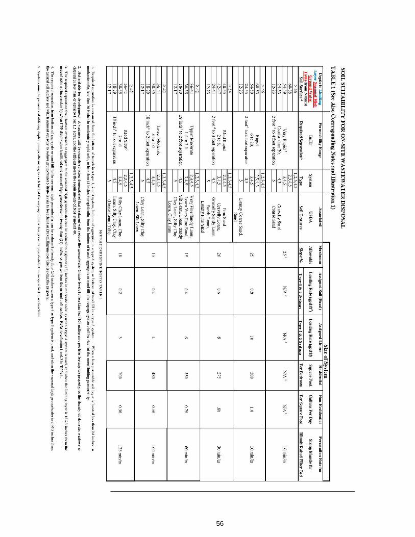
56
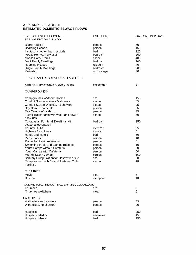
57
APPENDIX B – TABLE II ESTIMATED DOMESTIC SEWAGE FLOWS
TYPE OF ESTABLISHMENT UNIT (PER) GALLONS PER DAY PERMANENT DWELLINGS
Board Houses person 50 Boarding Schools person 150 Institutions, other than hospitals bed 125 Mobile Homes, individual bedroom 200 Mobile Home Parks space 400 Multi Family Dwellings bedroom 200 Rooming Houses resident 40 Single Family Dwellings bedroom 200 Kennels run or cage 30 TRAVEL AND RECREATIONAL FACILITIES Airports, Railway Station, Bus Stations passenger 5 CAMPGROUNDS
Campgrounds w/Mobile Homes site 150 Comfort Station w/toilets & showers space 35 Comfort Station w/toilets, no showers space 25 Day Camps, no meals person 25 Day Camps w/meals person 35 Travel Trailer parks with water and sewer space 50 hook-ups Cottages and/or Small Dwellings with bedroom 150 seasonal occupancy Country Clubs member 25 Highway Rest Areas traveler 5 Hotels and Motels bed 50 Picnic Parks person 10 Places for Public Assembly person 5 Swimming Pools and Bathing Beaches person 10 Youth Camps without Cafeteria person 50 Youth Camps with Cafeteria person 60 Migrant Labor Camps person 150 Sanitary Dump Station for Unsewered Site site 20 Campgrounds with Central Bath and Toilet space 35 Facilities THEATRES Movie seat 5 Drive-in car space 10
COMMERCIAL, INDUSTRIAL, and MISCELLANEOUS Churches seat 3 Churches w/kitchens meal 6
FACTORIES With toilets and showers person 35 With toilets, no showers person 20
Hospitals bed 250 Hospitals, Medical employee 15 Hospitals, Mental bed 150
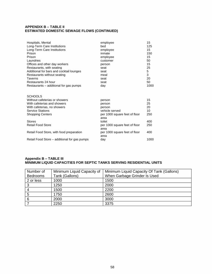
58
APPENDIX B – TABLE II ESTIMATED DOMESTIC SEWAGE FLOWS (CONTINUED)
Hospitals, Mental employee 15 Long-Term Care Institutions bed 125 Long-Term Care Institutions employee 15 Prison inmate 150 Prison employee 15 Laundries customer 50 Offices and other day workers person 15 Restaurants, with seating seat 25 Additional for bars and cocktail lounges seat 5 Restaurants without seating meal 3 Taverns seat 20 Restaurants 24 hour seat 50 Restaurants – additional for gas pumps day 1000 SCHOOLS Without cafeterias or showers person 15 With cafeterias and showers person 25 With cafeterias, no showers person 20 Service Stations vehicle served 10 Shopping Centers per 1000 square feet of floor
area 250
Stores toilet 400 Retail Food Store per 1000 square feet of floor
area 250
Retail Food Store, with food preparation per 1000 square feet of floor area
400
Retail Food Store – additional for gas pumps day 1000
Appendix B – TABLE III MINIMUM LIQUID CAPACITIES FOR SEPTIC TANKS SERVING RESIDENTIAL UNITS
Number of Bedrooms
Minimum Liquid Capacity of Tank (Gallons)
Minimum Liquid Capacity Of Tank (Gallons) When Garbage Grinder Is Used
2 or less 1000 1500
3 1250 2000
4 1500 2200
5 1750 2600
6 2000 3000
7 2250 3375
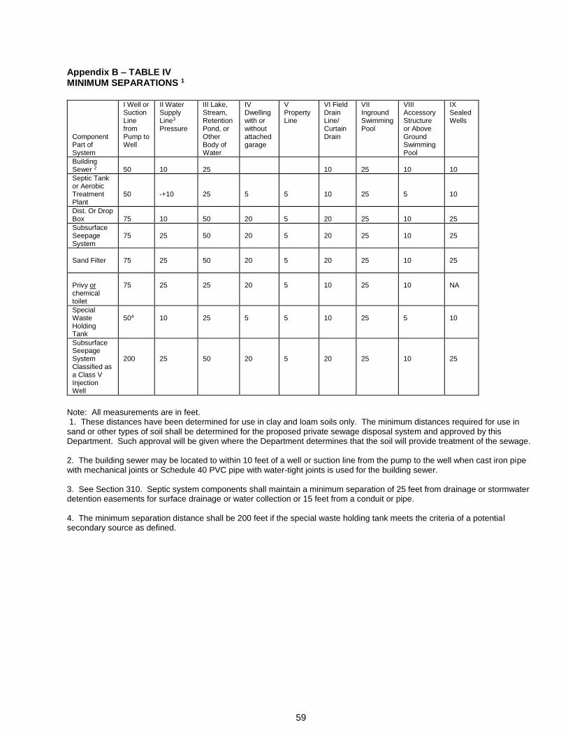
59
Appendix B – TABLE IV MINIMUM SEPARATIONS 1
Component Part of System
I Well or Suction Line from Pump to Well
II Water Supply Line3
Pressure
III Lake, Stream, Retention Pond, or Other Body of Water
IV Dwelling with or without attached garage
V Property Line
VI Field Drain Line/ Curtain Drain
VII Inground Swimming Pool
VIII Accessory Structure or Above Ground Swimming Pool
IX Sealed Wells
Building Sewer 2
50
10
25
10
25
10
10
Septic Tank or Aerobic Treatment Plant
50
-+10
25
5
5
10
25
5
10
Dist. Or Drop Box
75
10
50
20
5
20
25
10
25
Subsurface Seepage System
75
25
50
20
5
20
25
10
25
Sand Filter
75
25
50
20
5
20
25
10
25
Privy or chemical toilet
75
25
25
20
5
10
25
10
NA
Special Waste Holding Tank
504
10
25
5
5
10
25
5
10
Subsurface Seepage System Classified as a Class V Injection Well
200
25
50
20
5
20
25
10
25
Note: All measurements are in feet. 1. These distances have been determined for use in clay and loam soils only. The minimum distances required for use in sand or other types of soil shall be determined for the proposed private sewage disposal system and approved by this Department. Such approval will be given where the Department determines that the soil will provide treatment of the sewage. 2. The building sewer may be located to within 10 feet of a well or suction line from the pump to the well when cast iron pipe with mechanical joints or Schedule 40 PVC pipe with water-tight joints is used for the building sewer. 3. See Section 310. Septic system components shall maintain a minimum separation of 25 feet from drainage or stormwater detention easements for surface drainage or water collection or 15 feet from a conduit or pipe. 4. The minimum separation distance shall be 200 feet if the special waste holding tank meets the criteria of a potential secondary source as defined.
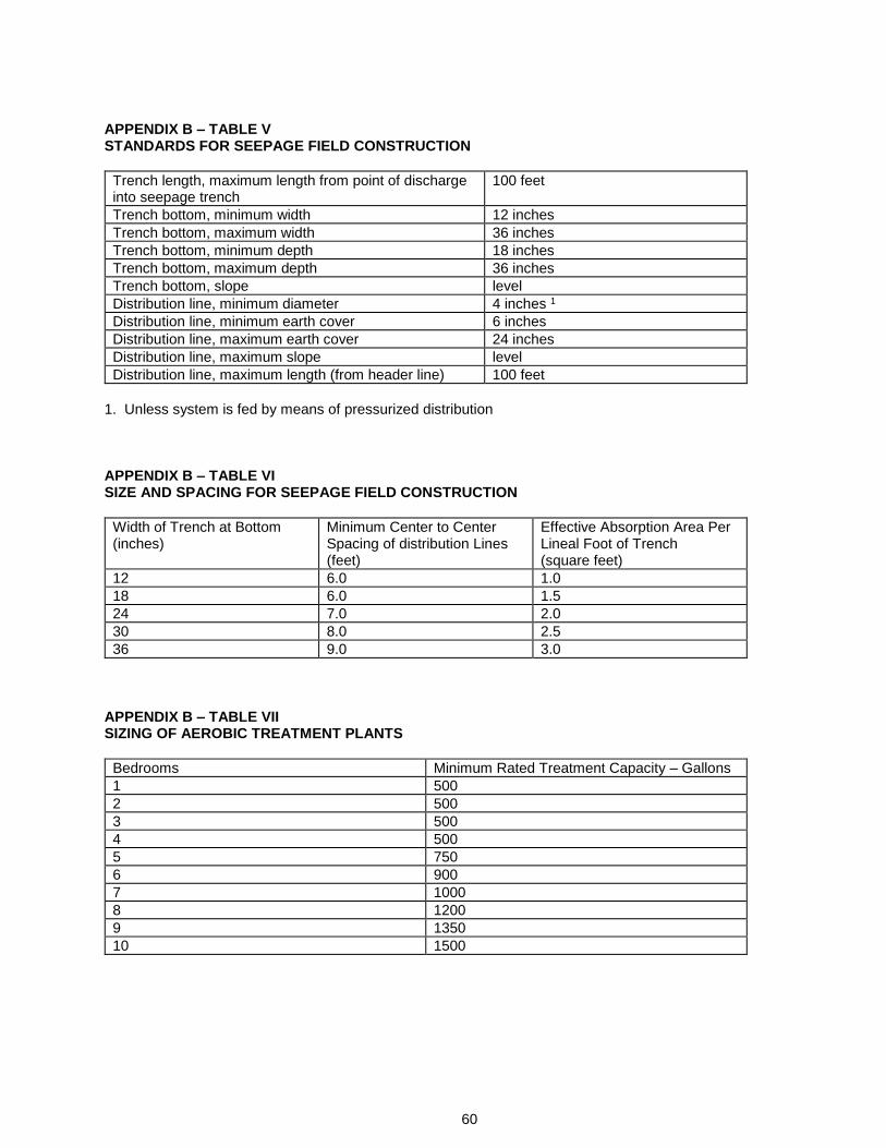
60
APPENDIX B – TABLE V STANDARDS FOR SEEPAGE FIELD CONSTRUCTION
Trench length, maximum length from point of discharge into seepage trench
100 feet
Trench bottom, minimum width 12 inches
Trench bottom, maximum width 36 inches
Trench bottom, minimum depth 18 inches
Trench bottom, maximum depth 36 inches
Trench bottom, slope level
Distribution line, minimum diameter 4 inches 1
Distribution line, minimum earth cover 6 inches
Distribution line, maximum earth cover 24 inches
Distribution line, maximum slope level
Distribution line, maximum length (from header line) 100 feet
1. Unless system is fed by means of pressurized distribution APPENDIX B – TABLE VI SIZE AND SPACING FOR SEEPAGE FIELD CONSTRUCTION
Width of Trench at Bottom (inches)
Minimum Center to Center Spacing of distribution Lines (feet)
Effective Absorption Area Per Lineal Foot of Trench (square feet)
12 6.0 1.0
18 6.0 1.5
24 7.0 2.0
30 8.0 2.5
36 9.0 3.0
APPENDIX B – TABLE VII SIZING OF AEROBIC TREATMENT PLANTS
Bedrooms Minimum Rated Treatment Capacity – Gallons
1 500
2 500
3 500
4 500
5 750
6 900
7 1000
8 1200
9 1350
10 1500
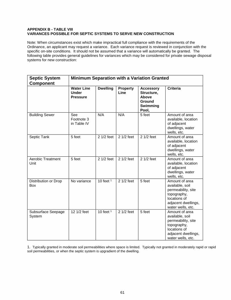
61
APPENDIX B - TABLE VIII VARIANCES POSSIBLE FOR SEPTIC SYSTEMS TO SERVE NEW CONSTRUCTION Note: When circumstances exist which make impractical full compliance with the requirements of the Ordinance, an applicant may request a variance. Each variance request is reviewed in conjunction with the specific on-site conditions. It should not be assumed that a variance will automatically be granted. The following table provides general guidelines for variances which may be considered for private sewage disposal systems for new construction:
Septic System Component
Minimum Separation with a Variation Granted
Water Line Under Pressure
Dwelling Property Line
Accessory Structure, Above Ground Swimming Pool,
Criteria
Building Sewer See Footnote 3 in Table IV
N/A N/A 5 feet Amount of area available, location of adjacent dwellings, water wells, etc.
Septic Tank 5 feet 2 1/2 feet 2 1/2 feet 2 1/2 feet Amount of area available, location of adjacent dwellings, water wells, etc.
Aerobic Treatment Unit
5 feet 2 1/2 feet 2 1/2 feet 2 1/2 feet Amount of area available, location of adjacent dwellings, water wells, etc.
Distribution or Drop Box
No variance 10 feet 1 2 1/2 feet 5 feet Amount of area available, soil permeability, site topography, locations of adjacent dwellings, water wells, etc.
Subsurface Seepage System
12 1/2 feet 10 feet 1 2 1/2 feet 5 feet Amount of area available, soil permeability, site topography, locations of adjacent dwellings, water wells, etc.
1. Typically granted in moderate soil permeabilities where space is limited. Typically not granted in moderately rapid or rapid
soil permeabilities, or when the septic system is upgradient of the dwelling.
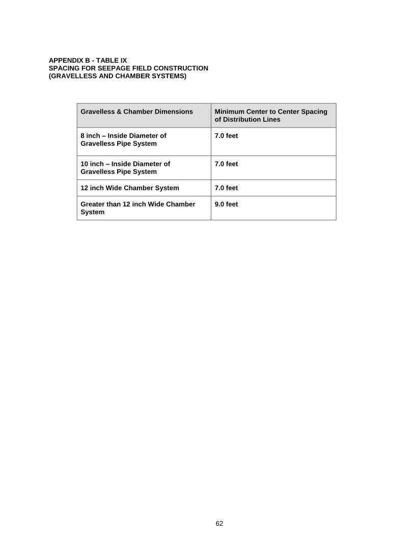
62
APPENDIX B - TABLE IX SPACING FOR SEEPAGE FIELD CONSTRUCTION (GRAVELLESS AND CHAMBER SYSTEMS)
Gravelless & Chamber Dimensions Minimum Center to Center Spacing of Distribution Lines
8 inch – Inside Diameter of Gravelless Pipe System
7.0 feet
10 inch – Inside Diameter of Gravelless Pipe System
7.0 feet
12 inch Wide Chamber System 7.0 feet
Greater than 12 inch Wide Chamber System
9.0 feet
63
APPENDIX C
A. Design Checklist B. Table X – Perforation Discharge Rates C. Table XI – Friction Loss in Schedule 40 Plastic Pipe D. Illustrations
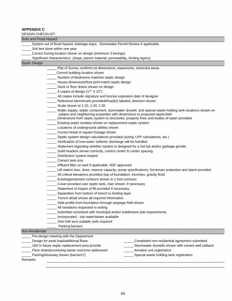
64
APPENDIX C DESIGN CHECKLIST:
Soils and Flood Hazard
_____ System out of flood hazard, drainage ways. Stormwater Permit Review if applicable.
_____ Soil test done within one year
_____ Correct boring location shown on design (minimum 3 borings)
_____ Significant characteristics (slope, parent material, permeability, limiting layers)
Septic Design
_____ Plat of Survey confirms lot dimensions, easements, restricted areas
_____Correct building location shown
_____ Number of Bedrooms matches septic design
_____ House dimensions/foot print match septic design
_____ Deck or floor drains shown on design
_____ 4 copies of design (17" X 22")
_____ All copies include signature and license expiration date of designer
_____ Reference benchmark provided/Road(s) labeled, direction shown
_____ Scale shown at 1:10, 1:20, 1:30
_____ Water supply, septic component, stormwater drywell, and special waste holding tank locations shown on subject and neighboring properties with dimensions to proposed septic/well
_____ Dimensions from septic system to structures, property lines and bodies of water provided
_____ Existing septic location shown on replacement septic system
_____ Locations of underground utilities shown
_____ Correct lineal or square footage shown
_____ Septic system design calculations provided (sizing, LPP calculations, etc.)
_____ Verification of how water softener discharge will be handled
_____ Statement regarding whether system is designed for a hot tub and/or garbage grinder
_____ Solid headers shown correctly, correct center to center spacing
_____ Distribution system looped
_____ Correct tank size
_____ Effluent filter on tank if applicable, NSF approved
_____ Lift station size, dose, reserve capacity, pump specifications, forcemain protection and alarm provided
_____ All critical elevations provided (top of foundation, trenches, gravity flow)
_____ Existing/proposed contours shown in 1 foot contours
_____ Cover provided over septic tank, riser shown; if necessary
_____ Statement of impact of fill provided if necessary
_____ Separation from bottom of trench to limiting layer
_____ Trench detail shows all required information
_____ Side profile from foundation through seepage field shown
_____ All variations requested in writing
_____ Submittal consistent with municipal and/or subdivision plat requirements.
_____ Incorporated - city water/sewer available
_____ One-half acre suitable soils required
_____ Parking barriers
Non-Residential
_____ Pre-design meeting with the Department
_____ Design for peak load/additional flows _____ Completed non-residential agreement submitted
_____ 100 % future septic replacement area provide _____ Stormwater drywells shown with correct well setback
_____ Floor drain/processing waste concerns addressed _____ Aeration unit registration
_____ Parking/driveway shown (barriers?) _____ Special waste holding tank registration
Remarks:
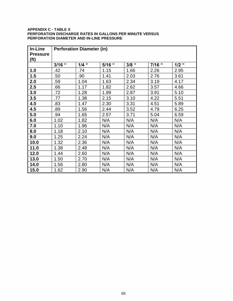
65
APPENDIX C - TABLE X PERFORATION DISCHARGE RATES IN GALLONS PER MINUTE VERSUS PERFORATION DIAMETER AND IN-LINE PRESSURE
In-Line Pressure (ft)
Perforation Diameter (in)
3/16 “ 1/4 “ 5/16 “ 3/8 “ 7/16 “ 1/2 “
1.0 .42 .74 1.15 1.66 2.26 2.95
1.5 .50 .90 1.41 2.03 2.76 3.61
2.0 .59 1.04 1.63 2.34 3.19 4.17
2.5 .66 1.17 1.82 2.62 3.57 4.66
3.0 .72 1.28 1.99 2.87 3.91 5.10
3.5 .77 1.38 2.15 3.10 4.22 5.51
4.0 .83 1.47 2.30 3.31 4.51 5.89
4.5 .89 1.56 2.44 3.52 4.79 6.25
5.0 .94 1.65 2.57 3.71 5.04 6.59
6.0 1.02 1.82 N/A N/A N/A N/A
7.0 1.10 1.96 N/A N/A N/A N/A
8.0 1.18 2.10 N/A N/A N/A N/A
9.0 1.25 2.24 N/A N/A N/A N/A
10.0 1.32 2.36 N/A N/A N/A N/A
11.0 1.38 2.48 N/A N/A N/A N/A
12.0 1.44 2.60 N/A N/A N/A N/A
13.0 1.50 2.70 N/A N/A N/A N/A
14.0 1.56 2.80 N/A N/A N/A N/A
15.0 1.62 2.90 N/A N/A N/A N/A
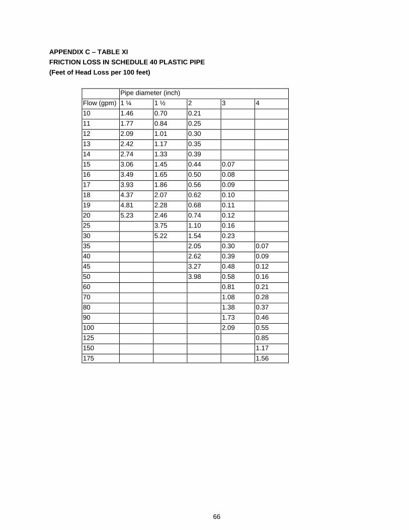
66
APPENDIX C – TABLE XI
FRICTION LOSS IN SCHEDULE 40 PLASTIC PIPE
(Feet of Head Loss per 100 feet)
Pipe diameter (inch)
Flow (gpm) 1 ¼ 1 ½ 2 3 4
10 1.46 0.70 0.21
11 1.77 0.84 0.25
12 2.09 1.01 0.30
13 2.42 1.17 0.35
14 2.74 1.33 0.39
15 3.06 1.45 0.44 0.07
16 3.49 1.65 0.50 0.08
17 3.93 1.86 0.56 0.09
18 4.37 2.07 0.62 0.10
19 4.81 2.28 0.68 0.11
20 5.23 2.46 0.74 0.12
25 3.75 1.10 0.16
30 5.22 1.54 0.23
35 2.05 0.30 0.07
40 2.62 0.39 0.09
45 3.27 0.48 0.12
50 3.98 0.58 0.16
60 0.81 0.21
70 1.08 0.28
80 1.38 0.37
90 1.73 0.46
100 2.09 0.55
125 0.85
150 1.17
175 1.56
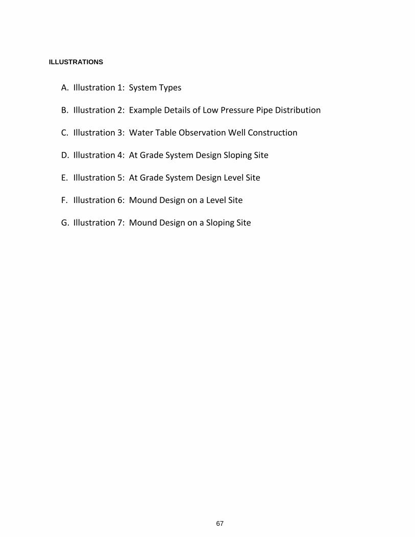
67
ILLUSTRATIONS
A. Illustration 1: System Types
B. Illustration 2: Example Details of Low Pressure Pipe Distribution
C. Illustration 3: Water Table Observation Well Construction
D. Illustration 4: At Grade System Design Sloping Site
E. Illustration 5: At Grade System Design Level Site
F. Illustration 6: Mound Design on a Level Site
G. Illustration 7: Mound Design on a Sloping Site
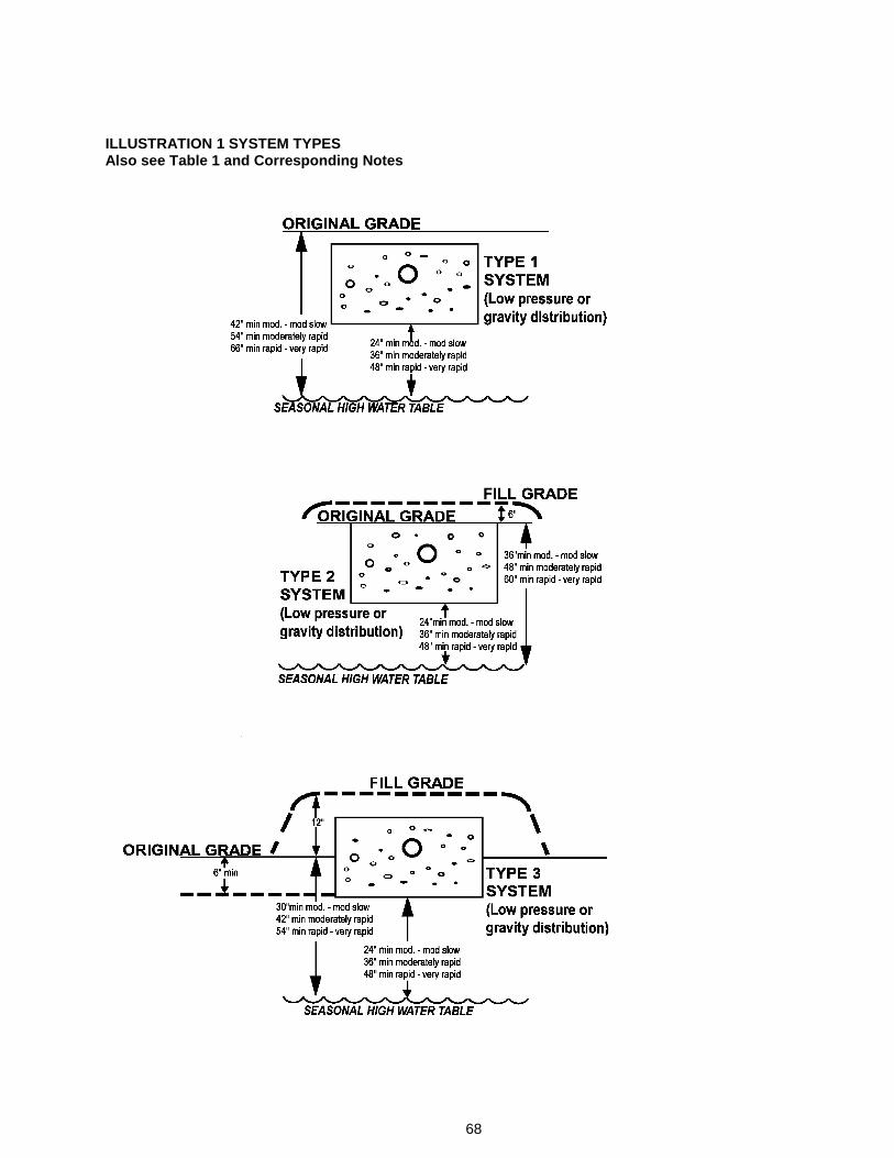
68
ILLUSTRATION 1 SYSTEM TYPES Also see Table 1 and Corresponding Notes
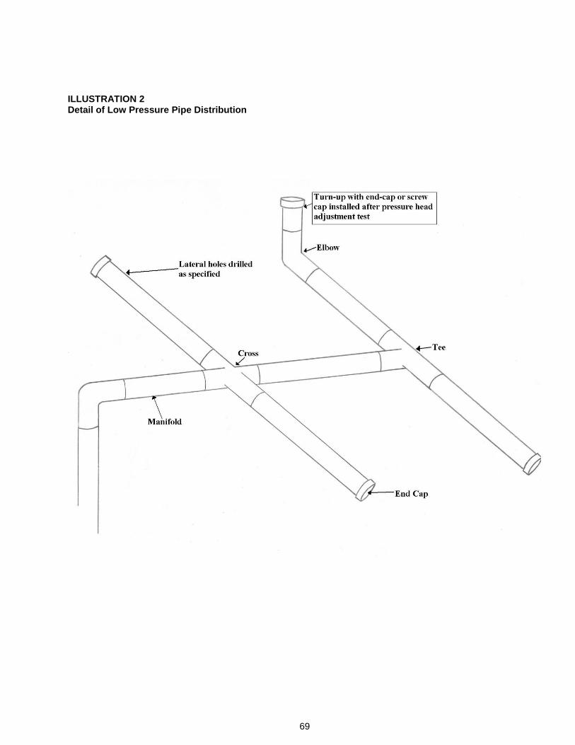
69
ILLUSTRATION 2 Detail of Low Pressure Pipe Distribution
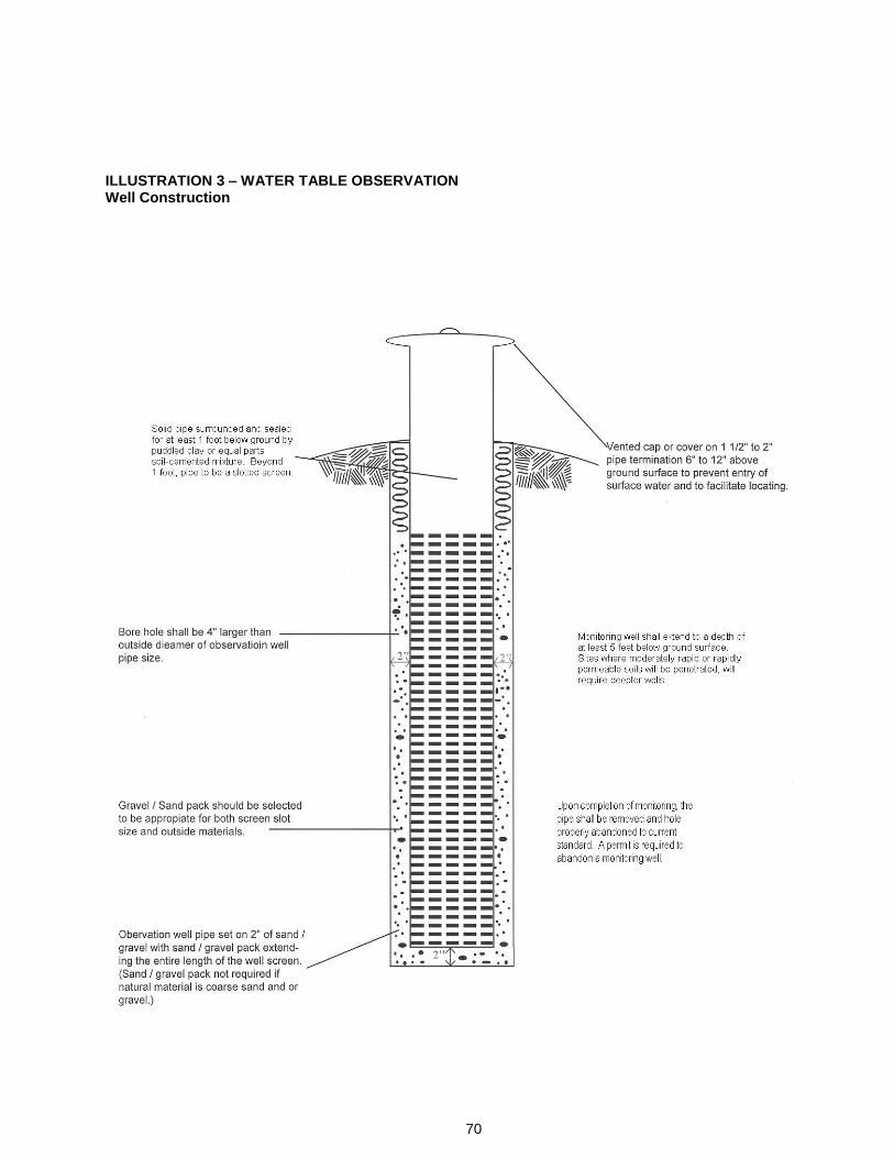
70
ILLUSTRATION 3 – WATER TABLE OBSERVATION Well Construction
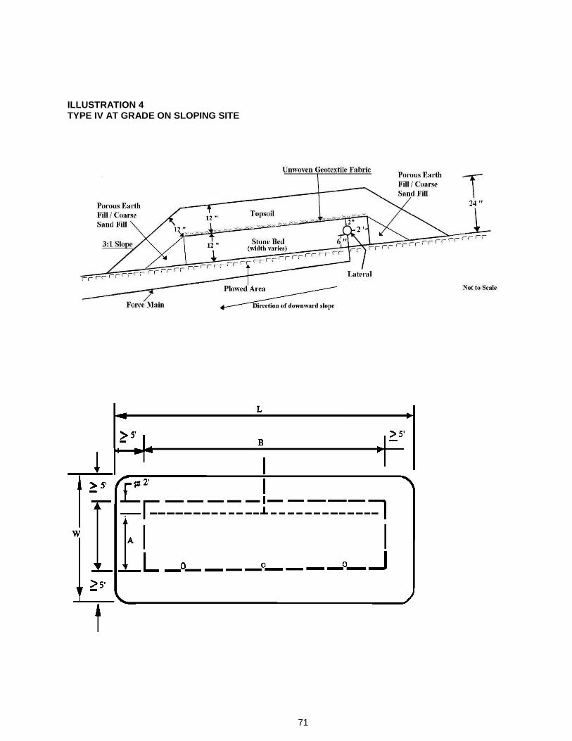
71
ILLUSTRATION 4 TYPE IV AT GRADE ON SLOPING SITE
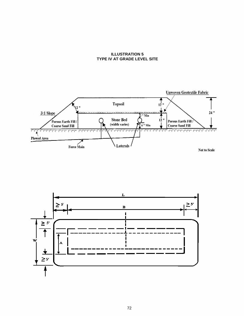
72
ILLUSTRATION 5
TYPE IV AT GRADE LEVEL SITE
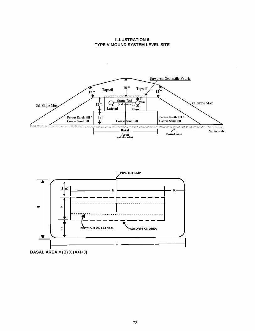
73
BASAL AREA = (B) X (A+I+J)
ILLUSTRATION 6
TYPE V MOUND SYSTEM LEVEL SITE
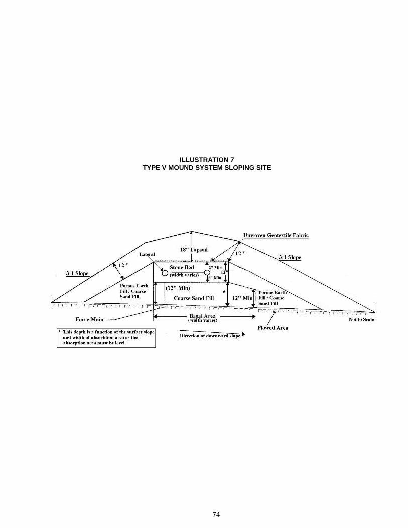
74
ILLUSTRATION 7
TYPE V MOUND SYSTEM SLOPING SITE
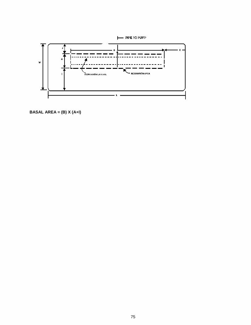
75
BASAL AREA = (B) X (A+I)