Embed Size (px)
Citation preview

696
ANNOUNCEMENT OF PUBLIC HEARINGS AND REQUEST FOR PUBLIC COMMENT
The New England District Corps of Engineers has received a permit application to conduct work in waters of the United States from ALGONQUIN GAS TRANSMISSION, LLC (AGT), 5400 WESTHEIMER COURT, HOUSTON, TEXAS 77056-5310 c/o Terry Doyle, AGT, LLC, 890 Winter Street, Waltham, Massachusetts, 02451. This work is proposed in wetlands and waters adjacent to the AGT MLV-19 pipeline in the City of Danbury, Connecticut; Line 36A in the towns of Cromwell and Rocky Hill, Connecticut and the E-1 system in the towns of Lebanon, Franklin, Norwich, and Montville, Connecticut. In the State of Massachusetts a new lateral pipeline is proposed off of the existing I-4 pipeline in the towns of Westwood, Dedham and West Roxbury. Work regulated by the Corps is water body crossings and the placement of permanent or temporary fill in wetlands and streams along the proposed natural gas pipeline route. Other portions of the proposed project with impact to waters of the United States will be undertaken in the State of New York and are the subject of a concurrent application to the New York District Corps of Engineers. The AIM project includes other facilities that are outside the purview of the Corps of Engineers (Corps). These include modification of four compressor stations (Cromwell, Chaplin and Oxford, CT and Burrillville, RI), upgrade of 13 existing metering stations (West Danbury, Southbury, Waterbury, North Haven, Guilford, Farmington, Glastonbury, Middletown, Salem, Montville, Willimantic, Pomfret and Putnam, CT), construction of three new metering stations (Oakland Heights, CT, Assonet and West Roxbury, MA) and removal of nine existing metering stations. These facilities will not impact waters of the United States and therefore do not require a permit from the Corps. The Federal Energy Regulatory Commission (FERC) is the lead Federal agency for this project which is identified as Docket No. CP14-96. As the lead agency, FERC has prepared a Draft Environmental Impact Assessment (DEIS) in accordance with the National Environmental Policy Act (NEPA). The DEIS includes a review under Section 7 of the Endangered Species Act (16 U.S.C. 1531) and Section 106 of the National Historical Preservation Act (NHPA), as well as other applicable Federal regulations. The DEIS was issued on August 6, 2014 and is expected to be published in the federal register during the week of August 18, 2014. The DEIS with accompanying instructions for submitting comments to the FERC is available for review at http://www.ferc.gov. Using the “eLibrary” link on the FERC website, select “General Search” from the eLibrary menu, enter the selected date range and the FERC “Docket No.” excluding the last three digits (i.e., CP14-96), and follow the instructions. For assistance, call 1-866-208-3676, or e-mail [email protected]. The DEIS is also available for download at the Corps website by going to http://www.nae.usace.army.mil/Missions/Regulatory/PublicNotices/tabid/11771/Article/494068/nae-2013-01233.aspx.
696 Virginia Road Concord, MA 01742-2751
PUBLIC NOTICE Comment Period Begins: August 19, 2014 Comment Period Ends: September 19, 2014 File Number: NAE-2013-1233 In Replying Refer to: Cori M. Rose Phone: (978) 318-8306 E-mail: [email protected]

CENAE-R FILE NO. NAE-2013-1233
2
FERC will hold public comment meetings on the DEIS for the proposed AIM Project within Connecticut and Massachusetts. The New England District Corps of Engineers will participate in the public comment meetings to gather information on the proposal to assist in the review of the permit application for the proposed activity. The dates and locations of the meetings are as follows:
Date Location Monday, September 8, 2014 6:30 pm
Holiday Inn, Dedham 55 Ariadne Road
Dedham, MA 02026 (781) 329-1000
Tuesday, September 9, 2014 6:30 pm
Holiday Inn, Norwich 10 Laura Boulevard Norwich, CT 06360
(860) 889-5201 Wednesday, September 10, 2014 6:30 pm
Danbury City Hall City Council Chambers 155 Deer Hill Avenue Danbury, CT 06810
(203) 797-4514 Tuesday, September 16, 2014 6:30 PM
Crystal Lake Golf Club 100 Bronco Highway Mapleville, RI 02839
(401) 567-4500 The AIM Project also includes work within New York under the regulatory boundary of the New York District Corps of Engineers that will be processed by the New York District under application number NAN-2014-00402-EYA. FERC will hold a public comment meeting in New York and the New York District Corps of Engineers will also participate in this public meeting. The New York Public Meeting is scheduled for Monday, September 15, 2014 at 6:30 PM at Muriel H. Morabito Community Center, 29 Westbrook Drive, Cortlandt Manor, NY 10567. The United States Army Corps of Engineers neither favors nor opposed the proposed construction work. The purpose of this public notice is to announce that the Corps of Engineers will participate in the FERC public comment meetings to receive and consider public comments on the material matters at issue with respect to activities regulated by the Corps. Project Description: The regulated work proposed by AGT in this permit application involves the discharge of permanent backfill over approximately 1.4 acres of waters and wetlands as pipeline trench backfill and discharge of temporary fill in wetlands and waters for construction in conjunction with the installation of 21.9 miles of new, and/or replacement, gas pipeline known as the Algonquin Incremental Market Project (AIM). Included in the project is the replacement of 13.5 miles of existing pipeline with new, larger pipeline and the installation of 8.4 miles of new pipeline with associated rights-of-way (ROW). New ROW will be obtained for three of the four project segments. This work will impact approximately 5,694 linear feet and 28.26 acres of waters of the United States and/or wetlands including aquatic resources affiliated with the Still River, Sawmill River, Kohanza Brook, Dividend Brook, Susquetonscut Brook, Johnnycake Brook, Elisha Brook, Stony Brook, and Falls Brook. In all it is estimated that 69 waterbodies and 86 wetland areas are proposed to be temporarily and/or permanently impacted in the states of Connecticut and Massachusetts.
CENAE-R FILE NO. NAE-2013-1233
3
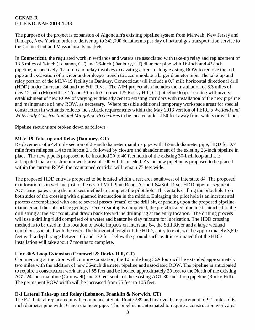
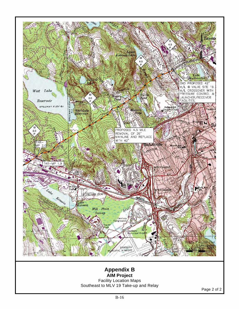
The purpose of the project is expansion of Algonquin's existing pipeline system from Mahwah, New Jersey and Ramapo, New York in order to deliver up to 342,000 dekatherms per day of natural gas transportation service to the Connecticut and Massachusetts markets. In Connecticut, the regulated work in wetlands and waters are associated with take-up relay and replacement of 13.5 miles of 6-inch (Lebanon, CT) and 26-inch (Danbury, CT) diameter pipe with 16-inch and 42-inch pipeline, respectively. Take-up and relay involves excavating a trench along existing ROW to remove the old pipe and excavation of a wider and/or deeper trench to accommodate a larger diameter pipe. The take-up and relay portion of the MLV-19 facility in Danbury, Connecticut will include a 0.7 mile horizontal directional drill (HDD) under Interstate-84 and the Still River. The AIM project also includes the installation of 3.3 miles of new 12-inch (Montville, CT) and 36-inch (Cromwell & Rocky Hill, CT) pipeline loop. Looping will involve establishment of new ROW of varying widths adjacent to existing corridors with installation of the new pipeline and maintenance of new ROW, as necessary. Where possible additional temporary workspace areas for special construction in wetlands reflects the setback requirements within the May 2013 version of FERC’s Wetland and Waterbody Construction and Mitigation Procedures to be located at least 50 feet away from waters or wetlands. Pipeline sections are broken down as follows: MLV-19 Take-up and Relay (Danbury, CT) Replacement of a 4.4 mile section of 26-inch diameter mainline pipe with 42-inch diameter pipe, HDD for 0.7 mile from milepost 1.4 to milepost 2.1 followed by closure and abandonment of the existing 26-inch pipeline in place. The new pipe is proposed to be installed 20 to 40 feet north of the existing 30-inch loop and it is anticipated that a construction work area of 100 will be needed. As the new pipeline is proposed to be placed within the current ROW, the maintained corridor will remain 75 feet wide. The proposed HDD entry is proposed to be located within a rest area southwest of Interstate 84. The proposed exit location is in wetland just to the east of Mill Plain Road. At the I-84/Still River HDD pipeline segment AGT anticipates using the intersect method to complete the pilot hole. This entails drilling the pilot hole from both sides of the crossing with a planned intersection in the middle. Enlarging the pilot hole is an incremental process accomplished with one to several passes (ream) of the drill bit, depending upon the proposed pipeline diameter and the subsurface geology. Once reaming is completed, the prefabricated pipeline is attached to the drill string at the exit point, and drawn back toward the drilling rig at the entry location. The drilling process will use a drilling fluid comprised of a water and bentonite clay mixture for lubrication. The HDD crossing method is to be used in this location to avoid impacts on Interstate 84, the Still River and a large wetland complex associated with the river. The horizontal length of the HDD, entry to exit, will be approximately 3,697 feet with a depth range between 65 and 172 feet below the ground surface. It is estimated that the HDD installation will take about 7 months to complete. Line-36A Loop Extension (Cromwell & Rocky Hill, CT) Commencing at the Cromwell compressor station, the 1.3 mile long 36A loop will be extended approximately two miles with the addition of new 36-inch diameter pipeline and associated ROW. The pipeline is anticipated to require a construction work area of 85 feet and be located approximately 20 feet to the North of the existing AGT 24-inch mainline (Cromwell) and 20 feet south of the existing AGT 30-inch loop pipeline (Rocky Hill). The permanent ROW width will be increased from 75 feet to 105 feet. E-1 Lateral Take-up and Relay (Lebanon, Franklin & Norwich, CT) The E-1 Lateral replacement will commence at State Route 289 and involve the replacement of 9.1 miles of 6-inch diameter pipe with 16-inch diameter pipe. The pipeline is anticipated to require a construction work area

CENAE-R FILE NO. NAE-2013-1233
4
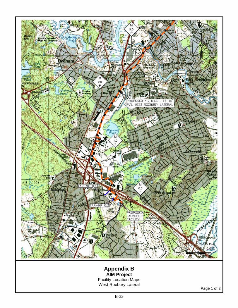
of 75 feet and be located, in general, 20 feet away from the AGT 10-inch E-1L line. The permanent ROW width will be increased from 50 feet to 60 feet. E-1 Lateral System Loop (Montville, CT) Commencing at the Montville Metering & Regulation station, this phase of the project will extend the existing E-1L system approximately 1.3 miles with installation of new 12-inch diameter pipeline and associated ROW. The pipeline is anticipated to require a construction work area of 75 feet and be located 15 feet away from the existing AGT 6-inch E-1 line. The permanent ROW width will be increased from 30 feet to 50 feet. In Massachusetts, the Corps regulated work will include stream crossings for construction of 5.1 miles of new 16-inch (Westwood and Dedham, MA) and 24-inch (West Roxbury, MA) diameter lateral pipeline. West Roxbury Lateral I-4 (Westwood, Dedham and West Roxbury, MA) This portion of the project is construction of a new 5.1 mile lateral pipeline. Approximately 4.2 miles will consist of installation of new 16-inch diameter pipe and approximately 0.9 mile will consist of 24-inch diameter pipe. The pipeline is anticipated to require a construction work area of 75 feet and the permanent ROW width will be increased from its current width of 50 feet. Temporary impact to wetlands and waters will result from a variety of project-related activities including installation and removal of erosion and sediment controls (E&SC); water handling, including installation and removal of pumps and temporary pipe diversions; installation and removal of temporary cofferdams and/or sandbag diversions; and discharge of temporary fill for construction access and/or stockpiling of material for trench backfill. Approximately 10 acres (35.3% of total wetland resource) of forested wetland and 18 acres (36.4% of total wetland resource) of non-forested wetlands will be temporarily impacted for pipeline access and construction. Secondary impact to wetlands and waters are those effects on an aquatic ecosystem that are associated with a discharge of fill material, but do not result from the actual placement of the fill. Secondary impacts from the proposed work may include permanent conversion of forested habitat within the new right of way to scrub shrub or emergent vegetated habitat; temporal loss of forested habitat function as a result of the loss of tree cover/temporary conversion in wetlands for establishment of the construction work area; removal of forest canopy cover over streams for construction installation and/or long-term maintenance within the new ROW; and zone edge effects such as removal of tree canopy cover in close proximity to vernal pools or changes to adjacent hydrology as a result of a reduction in evapotranspiration. Secondary impacts will include, but are not limited to, 1.43 acre of forested wetland conversion to either emergent or scrub shrub wetland type within the newly established ROW. Permanent impact to wetlands or waters may include compaction of hydric soils during placement of construction equipment that alters the surface of subsurface movement of water or upheaval (displacement) of soil following the placement of temporarily stock-piled materials. Although there will be a discharge of permanent fill within wetland for pipe installation, the discharge is not anticipated to result in the permanent loss of wetland acreage. Impact to Aquatic Resources: Waters along the proposed pipeline route were documented and delineated by the present of ordinary high water. Wetlands were field delineated in accordance with the Interim Regional Supplement to the Corps of Engineers Wetland Delineation Manual: Northcentral and Northeast Region.

CENAE-R FILE NO. NAE-2013-1233
5
In Connecticut and Massachusetts the proposed pipeline will cross, or otherwise impact, the following aquatic resources:
Waterbodies Crossed by the AIM Project Waterbody Name Municipality Width of Crossing
(range/ft) # of Crossings Tributary Type/Fishery
Present
CONNECTICUT *UNT = Unnamed tributary Southeast to MLV 19 Take-up & Relay Sawmill River Danbury 8 1 Warmwater UNT to Still River Danbury 0.5 to 9 2 Warmwater Still River* Danbury 12 1 Warmwater (trout) UNT* to Boggs Pond Brook Danbury 1-6 3 Warmwater Boggs Pond Brook Danbury 8 1 Warmwater UNT Kohanza Brook Danbury 4 1 Warmwater Kohanza Brook Danbury 12 1 Warmwater Line 36-A Loop Extension Coles Brook Cromwell 4 1 Warmwater UNT to Dividend Brook Cromwell 1-2 5 Coldwater Dividend Brook Cromwell 10-21 5 Coldwater (trout) E-1 System Lateral Take-up & Relay Susquetonscut Brook Lebanon 29-37 3 Warmwater (trout) UNT to Susquetonscut Brook Lebanon, Franklin 0.5-17 30 Warmwater (trout) Johnnycake Brook Franklin 56 1 Warmwater UNT to Elisha Brook Franklin 1 1 Coldwater (trout) UNT to Norwichtown Brook Norwich 1-2 4 Warmwater E-1 System Lateral Loop UNT to Stony Brook Montville 1-13 6 Coldwater (trout) Falls Brook Montville 25 1 Coldwater (trout)
MASSACHUSETTS West Roxbury Lateral UNT to Purgatory Brook Dedham 9 1 Warmwater Mother Brook Dedham 41 1 Warmwater
Summary of Wetland Impacts Resulting from Construction and Operation of the AIM Project
Connecticut Wetland Impact
Total Crossing Length (ft)*
Total Wetland Impact Construction (ac)
Total Wetland Impact
Operation (ac)
Forested Wetland Impact
Construction (ac)
Forested Wetland Impact
Operation (ac) Southeast to MLV 19 Take-up and Relay
5,435.2 8.2 0.0 2.5 0.0
Line-36A Loop
1,676.2 2.6 0.8 0.9 0.5
E-1 System Lateral Take-up and Relay
8,979.2 15.8 1.7 5.5 0.6
E-1 System Lateral
1,080.5 1.7 0.5 1.1 0.4
Connecticut Total 17,171.2 28.3 3.0 10.0 1.5 Massachusetts Wetland
0.0 0.0 0.0 0.0 0.0
Massachusetts Total 0.0 0.0 0.0 0.0 0.0 CUMULATIVE TOTAL 17,171.2 feet 28.3 acres 3.0 acres 10 acres 1.5 acres
* Crossing length of pipeline where the pipeline center crosses the wetland.

CENAE-R FILE NO. NAE-2013-1233
6
AGT evaluated wetlands within the study corridor and identified those areas that had the potential to serve as vernal pool habitat based on an evaluation of visible vernal pool indicators. Potential vernal pool habitat was characterized in accordance with Corps methodology. A total of five potential vernal pools (“PVPs”) and four confirmed vernal pools were identified along the AIM project pipeline segments in the New England District. No direct impacts are expected to occur at seven of the nine identified pools. These pools are outside of the Project’s temporary work space, and no clearing or crossing of these resources is to occur. One of the pools in Connecticut (B13-ELR-VP19) along the E-1 System Take-up & Relay in the Town of Franklin is partially located inside the temporary pipeline workspace , but not within the permanent ROW. In this area the temporary work space will be cleared of vegetation, but upon completion of the Project, the area will be allowed to re-vegetate and return to its previous community type. Another pool along the E-1 Take-up & Relay in the Town of Lebanon, Connecticut (A13-ELR-VP9) is located both in the temporary work space and the permanent ROW. At this location, 141 square feet will be permanently converted from forested upland vegetative habitat to an open vegetative habitat. The list of potential and confirmed vernal pools is provided below:
Wetland and Waterbody Construction Methodology: Unless a stream is dry and has no perceptible flow at the time of the pipeline crossing, a “dry crossing” method will be used for installation of the pipe. A “dry crossing” method involves installation of a flume pipe(s)
List of Vernal Pools and Potential Vernal Pools along the AIM Project Pipeline
Vernal Pool Milepost Town, State Status a/ Description Temporary
(Square feet)
b/
Permanent
(Square Feet) c/
Southeast to MLV 19 Take-Up and Relay
A13-SELR-VP4 2.7 Danbury, CT PVP PVP located along the edge of the
temporary work space, and will not be impacted by construction
0.0 0.0
Line 36A Loop Extension
B13-CLR-VP1 0.1 Cromwell, CT VP VP located within the 300’ study corridor, not impacted by construction 0.0 0.0
E-1 System Lateral Take-Up and Relay
A13-ELR-VP6 2.7 Lebanon, CT VP VP located within the 300’ study corridor, not impacted by construction 0.0 0.0
A13-ELR-VP6A 3.0 Lebanon, CT PVP PVP located within the 300’ study corridor, not impacted by construction 0.0 0.0
A13-ELR-VP7 3.1 Lebanon, CT PVP PVP located within the 300’ study corridor, not impacted by construction 0.0 0.0
A13-ELR-VP9 3.4 Lebanon, CT PVP PVP located within the temporary work space of the Project. 523 141
A13-ELR-VP13 6.9 Franklin, CT VP VP located within the 300’ study corridor, not impacted by construction. 0.0 0.0
B13-ELR-VP19 8.3 Franklin, CT VP VP located within the temporary work space of the Project. 600 0.0
Burrillville Compressor Station
A13-BCS-PVP1 N/A Burrillville, RI PVP PVP located within the compressor station study area, not impacted by
construction 0.0 0.0
a/ VP : feature is a confirmed vernal pool, PVP = Feature requires additional surveys to confirm vernal pool status b/ The amount of area (in square feet) of the feature which will be temporarily impacted by the construction work space of the Project. These areas will be
allowed to re-vegetate. c/ The amount of area (in square feet) of the feature which will be permanently converted from forested upland vegetative habitat to an open land
vegetative habitat.

CENAE-R FILE NO. NAE-2013-1233
7
and/or a dam and pump before trenching begins to divert the stream flow over the construction area and allow trenching of the stream crossing in drier conditions and isolated from the stream flow. Spoil removed during the trenching would be stored away from the water’s edge and protected by sediment containment structures. Pipe strings would be fabricated on one bank and either pulled across the stream bottom to the opposite bank, or carried into place and lowered into the trench. Excavation and backfilling of the trench would be accomplished using backhoes or other excavation equipment working from the banks of the waterbody and vegetation will not be cleared for equipment access except over the pipeline trench, within 10 feet of the waterbody. There are six tributaries (UNT to Kohanza Brook, Kohanza Brook, UNT to Susquetonscut Brook (2 crossings), Susquetonscut Brook and UNT to Stony Brook) where the presence of shallow bedrock may require drilling and/or blasting for installation of the pipeline in Connecticut. In order to identify the need for drilling or blasting at these locations and others throughout the project area, the trench crew will drill and/or probe the stream banks to determine if rock is to be encountered during construction. Should these test holes identify the need for blasting, the ditch crew would prepare the trench line for blasting. When blasting is complete, the mainline tie-in crews would then excavate the trench, install the pipeline, and restore the area. AGT has identified methodologies for rock removal in its application to minimize adverse impact associated with blasting and impacted stream beds are proposed to be restored. In general, clearing of vegetation will be minimized for construction of the project since existing ROW and roadways are proposed to be used for a significant portion of the work. Clearing of vegetation in wetlands for installation is expected to be limited to trees and shrubs, which will be cut flush with the ground surface and then removed. To avoid excessive disruption of wetland soils and the native seed and rootstock within, stump removal will be limited to the area immediately over the trench line. Following vegetative clearing above ground, sediment barriers will be installed upslope of wetlands and where necessary to segregate wetlands and waters from ground disruption. All sediment barriers will be maintained during construction and replaced/repaired as necessary until permanent stabilization and/or restoration is complete. If trench dewatering in wetland areas is necessary, pumped water will be discharged into stable, vegetated, upland areas and/or filtered through a filter bag or siltation barrier. No heavily silt-laden water will be allowed to flow into the wetland. Construction methods are specified to minimize the amount of time and aerial extent that equipment will be operated in wetland areas. The pipeline trench will be excavated across wetland areas by equipment supported on wooden swamp mats or equivalent to minimize the disturbance to wetland soils. The top 12-inches of wetland soil over the trench line will be removed, temporarily piled in a ridge along the pipeline trench and segregated by type for reuse. Gaps in the spoil pile will be left at appropriate intervals to provide for natural circulation or drainage of water. If dry conditions exist within the wetland, the pipe fabrication is expected to occur in the wetland. For inundated or saturated wetland conditions, pipe strings are proposed to be fabricated on one bank and either pulled across the excavated trench in the wetland, floated across the wetland, or carried into place and submerged into the trench. Prior to backfilling, trench plugs would be installed where necessary to prevent the subsurface drainage of water from wetlands. After the pipeline is lowered into the trench, wide track bulldozers or backhoes supported on swamp mats would be used to backfill the pipe in the trench. Where topsoil has been segregated from subsoil, the subsoil will be backfilled first followed by the topsoil. Restoration of contours is expected to occur during backfilling. Equipment mats, terra mats, and timber riprap would be removed from wetlands following backfilling. Where wetlands are located at the base of slopes, permanent interceptor dikes and trench plugs would be installed in upland areas adjacent to the wetland boundary. Temporary sediment barriers would be installed where necessary until re-vegetation of adjacent upland areas is successful. Sediment and erosion control barriers will be removed once the site is fully stabilized.

CENAE-R FILE NO. NAE-2013-1233
8
Avoidance, Minimization and Compensation: Where possible, Algonquin uses take-up and relay construction to avoid establishment of new ROW. Where take-up and relay is not feasible, pipeline loop has been sited adjacent to existing ROW. Where use of existing ROW is not feasible (West Roxbury Lateral) the applicant uses existing roads, commercial or industrial lots, or other utility ROW to avoid and minimize impact. On-site restoration for temporarily impacted wetland habitat is proposed. Within 6 working days of substrate replacement, weather condition permitting, palustrine inland wetlands will typically be seeded with annual ryegrass at a rate of 40 pounds per acre. The use annual ryegrass in restoration is recommended by the National Resources Conservation Services (NRCS) and has been shown to effectively stabilize a site and serve as a nursery crop to prevent invasive encroachment as the indigenous wetland vegetation reestablishes itself. The ryegrass quickly loose vigor during the first growing season and allows re-vegetation by native wetland plant species. Palustrine forested wetland located in temporary work space (TWS) outside the permanent pipeline ROW and impacted by the construction will be restored. Restoration would include re-planting efforts, as necessary, combined with invasive species control and post planting monitoring. Plant species that readily resprout from stumpage (e.g., red maple) would be allowed to grow in place. Where construction has removed stumps or where resprouting does not appear feasible, a plan would be initiated to re-establish the PFO to a similar species composition and density as existed prior to construction. Native, locally-sourced plant materials would be used. All trees plantings would be potted nursery stock, at least 24-inches tall. To reduce competition from weedy species, each planted tree would be surrounded with a thick, organic mulch layer, at least four inches thick and with a radius of at least four-feet centered on the plant. Rodent guards would be placed around each tree, to a height of at least 12 inches above the ground. Additionally, Algonquin proposed to conduct post-construction maintenance and monitoring of the ROW in affected wetlands to assess the success of restoration and re-vegetation. Monitoring efforts would include documenting occurrences of exotic invasive species to compare to pre-construction conditions. On-site restoration for stream crossings would re-establish the original stream bed and bank contours, and mulch, jute thatching, or bonded fiber blankets would be installed on the stream banks to prevent erosion and encourage reestablishment of vegetation cover. Disturbed riparian areas would be re-vegetated with conservation grasses and legumes in accordance with the recommended Upland Seed Mix. Where necessary, slope breakers (i.e., interceptor dikes) would be installed adjacent to stream banks to minimize the potential for erosion. Temporary sediment barriers, such as silt fence or straw bales, would be maintained across the ROW until a permanent vegetation cover is established. To compensate for unavoidable impacts to waters of the United States as a result of the intended work, the applicant proposes to make payment to the Audubon Connecticut In-Lieu Fee Program in Connecticut and the Commonwealth of Massachusetts In-Lieu Fee Program in Massachusetts. Project Purpose: The purpose of the project is expansion of Algonquin's existing pipeline system from Mahwah, New Jersey and Ramapo, New York in order to deliver up to 342,000 dekatherms per day of natural gas transportation service to the Connecticut and Massachusetts markets. The capacity for the proposed delivery will be achieved through a combination of increased compression, replacement of existing pipeline, extension of existing pipeline loop and construction of new lateral pipe. An overview of the proposed pipeline route and typical methodologies for waterway and wetland crossings is attached. Detailed water of the United States impact area crossings are shown on project plans entitled

CENAE-R FILE NO. NAE-2013-1233
9
“ALGONQUIN INCREMENTAL MARKET PROJECT, SITE SPECIFIC WETLAND AND WATERBODY CROSSING PLAN” in 114 sheets, dated February 28, 2014. These plans, the project “WETLAND AND WATERWAY SURVEY MAPS” (66 sheets), the FERC Draft Environmental Impact Statement and associated appendices can be viewed and downloaded off of the New England District Corps of Engineers website at http://www.nae.usace.army.mil/Missions/Regulatory/PublicNotices/tabid/11771/Article/494068/nae-2013-01233.aspx AUTHORITY: Permits are required pursuant to:
____ Section 10 of the Rivers and Harbors Act of 1899 _X_ Section 404 of the Clean Water Act ____ Section 103 of the Marine Protection, Research and Sanctuaries Act
The decision whether to issue a permit will be based on an evaluation of the probable impact of the proposed activity on the public interest. That decision will reflect the national concern for both protection and utilization of important resources. The benefit which may reasonably accrue from the proposal must be balanced against its reasonably foreseeable detriments. All factors which may be relevant to the proposal will be considered, including the cumulative effects thereof; among those are: conservation, economics, aesthetics, general environmental concerns, wetlands, cultural value, fish and wildlife values, flood hazards, flood plain value, land use, navigation, shoreline erosion and accretion, recreation, water supply and conservation, water quality, energy needs, safety, food production and, in general, the needs and welfare of the people. The Corps of Engineers is soliciting comments from the public; Federal, state, and local agencies and officials; Indian Tribes; and other interested parties in order to consider and evaluate the impacts of this proposed activity. Any comments received will be considered by the Corps of Engineers to determine whether to issue, modify, condition or deny a permit for this proposal. To make this decision, comments are used to assess impacts on endangered species, historic properties, water quality, general environmental effects, and the other public interest factors listed above. Comments are used in the preparation of an Environmental Assessment and/or an Environmental Impact Statement pursuant to the National Environmental Policy Act. Comments are also used to determine the need for a public hearing and to determine the overall public interest of the proposed activity. Where the activity involves the discharge of dredged or fill material into waters of the United States or the transportation of dredged material for the purpose of disposing it in ocean waters, the evaluation of the impact of the activity in the public interest will also include application of the guidelines promulgated by the Administrator, U.S Environmental Protection Agency, under authority of Section 404(b) of the Clean Water Act, and/or Section 103 of the Marine Protection Research and Sanctuaries Act of 1972, as amended. Besides FERC, the proposed work is also being coordinated with the following Federal, State and local agencies:
• U.S. Environmental Protection Agency • U.S. Department of the Interior, Fish and Wildlife Service • Connecticut Depts. of Energy and Environmental Protection, Transportation, Historical Commission • Massachusetts Depts. of Environmental Protection, Transportation and Natural Heritage • Rhode Island Depts. of Environmental Management, Transportation,

CENAE-R FILE NO. NAE-2013-1233
All comments regarding the aforementioned permit application should be submitted in writing and reach this office before the expiration date of th is notice, otherwise. it wi II be presumed that there arc no objections to the activity. All comments provided to this office will become a part of the public record for this action.
In order to properly evaluate the proposaL we a1·e seeking public comment. Anyone wishing to comment is encouraged to do so. Comments should be submitted in wtiting by the above date. If you have any questions. please contact Ms. Cori M. Rose at (978) 318-8306. (800) 343-4789 or (800) 362-4367. if call ing from witrun Massachusetts.
The initial determinations made herein will be reviewed in light of facts submitted in response to this notice. AIJ comments will be considered a matter of public record. Copies of letters of objection will be forwarded to the applicant who will normally be requested to contact objectors directly in an effort to reach an understanding.
THIS NOTICE IS NOT AN AUTHORIZATION TO 0 0 ANY WORK.
Robert J .'DeSista C hief, Permits and Enforcement Branch New E ngland Regulatory Division
If you would prefer not to continue receiving Public Notices by email, please contact Ms. Tina Chaisson at (978) 318-8058 or e-mail her at I '- L!. _ . You may also check here ( ) and return this portion oft he Public Notice to: Bettina Chaisson, Regulatory Ojvision, U.S. Anny Corps of Engineers, 696 Virginia Road~ Concord, MA 01742-2751.
NAME: ADDRESS: PHONE:
10

AIM Project Public and Agency Participation Plan February 2014
Appendix A: Map
AIM Project Facilities Ramapo to Pts East 342,000 Dth/d
COLOR KEY
2016 Con~uuc6on
l I
NY Oxfotd C/S Modtflcation
Southeast C/S Add.tionaJ Compression
Chaplin C/S Ad<.1Jnonal Com res.sloa A
CromweUC/S Addltiooal Compressloo
I
I ,, \\1., \ J._.../ ' ~\ \
' ' ' ' ' ' ' ' ' ' ' ,..,, -\ "' ' ~' \ ~
Cromwell Discharge 2.0 ml 36 '"' toop
Southeast to M LV-19 4.4 ml l &R 26"w/42" Rt 84 HOD 10.7 mlles
Hudson to M P 91.2 6.Arnl l&R26"w 42"
V<.~n'<"'lel'> f(•• St<mvOot,ltoMP 91.2 ;~nd Soul'-1 to 1At.V·19 wll bi'
nJm:llut~'" !015
Rl
'\ West Roxbury lateral
4.3 .m1 New 16 .. 0.8 mJ New 24 ..
E-1 System g.l ml l&R 6 .. w/16,.
Meter St a t1ons 3 new mete-c stations
24 meter stanons need detailed ret/lew
AIM Project - 342,000 Dth/d Facil ities Diagram
Rev: 10-February-2014

")
")
")
")
")
")
")")
")
")
")
")
")")
")
")
")
")
")
")
")
")
")
")
")
")
")
")
")
")
")")
")")
E-1-System T&R (9.1 Miles)
Stony Point to Yorktown T&R (12.3 Miles)
Southeast to MLV 19 T&R (4.5 Miles)
Haverstraw to Stony Point T&R (3.3 Miles)
Line-36A Loop Extension (2.0 Miles)
West Roxbury Lateral-5.1 Miles 16"/24" Pipeline
E-1-System Loop (1.3 Miles)
Chaplin C/S
Cromwell C/S
Burrillville C/S
Southeast C/S
Stony Point C/S
Oxford C/S
BERGEN
WORCESTER
HAMPDEN
BERKSHIRE
BRISTOL
HAMPSHIRE
NORFOLK
MIDDLESEXFRANKLIN
SUFFOLK
PLYMOUTH
ESSEX
BARNSTABLE
SUFFOLK
DUTCHESSULSTER
COLUMBIAGREENE
ORANGE PUTNAM
WESTCHESTERROCKLAND
ALBANYRENSSELAER
NASSAU
LITCHFIELD HARTFORD
FAIRFIELD
WINDHAM
NEW HAVEN NEWLONDON
TOLLAND
MIDDLESEX
KENT
PROVIDENCE
WASHINGTONNEWPORT
N E W Y O R K
M A S S A C H U S E T T S
C O N N E C T I C U T
N E W H A M P S H I R EV E R M O N T
R H O D E I S L A N D
N E W J E R S E Y
MYSTIC
PUTNAMPOMFRET
NEEDHAM
BROCKTON
GUILFORD
WATERBURY
WELLESLEY
MONTVILLESOUTHBURY
CORTLANDT
PEEKSKILL
MIDDLETOWN
FARMINGTON
PROPOSEDOAKLANDHEIGHTS
SALEM PIKE
GLASTONBURY
NORTH HAVEN
WILLIMANTICNEW
BEDFORD
WEST DANBURY
NORWOOD
PROPOSED WEST ROXBURY
PROPOSEDASSONET
MIDDLEBOROUGH
STONYPOINT
NORTH FALL RIVER ")
GREENVILLE
Prepared on 2/17/2014
Project Facilities
K0 10 20
Miles
AIM ProjectFigure 1.1-1
Existing Algonquin Natural Gas PipelinesState BoundaryCounty Boundary
Legend") Compressor Station (C/S)") Meter Station
Proposed Pipeline-Take-up and Relay (T&R)-Loop-Lateral

Appendix BAIM Project
Facility Location MapsSoutheast to MLV 19 Take-up and Relay
Page 1 of 2
B-15
Appendix BAIM Project
Facility Location MapsSoutheast to MLV 19 Take-up and Relay
Page 2 of 2
B-16

Appendix BAIM Project
Facility Location MapsE-1 System Lateral Take-up and Relay
Page 1 of 3
B-19
Appendix BAIM Project
Facility Location MapsE-1 System Lateral Take-up and Relay
Page 2 of 3
B-20

Appendix BAIM Project
Facility Location MapsE-1 System Lateral Take-up and Relay
Page 3 of 3
B-21

Appendix BAIM Project
Facility Location MapsLine-36-A Loop Extension
B-25

Appendix BAIM Project
Facility Location MapsE-1 System Lateral Loop Extension
B-29
Appendix BAIM Project
Facility Location MapsWest Roxbury Lateral
Page 1 of 2
B-33

Appendix BAIM Project
Facility Location MapsWest Roxbury Lateral
Page 2 of 2
B-34

1. Survey and Staking2. Clearing3. Front-End Grading4. ROW Topsoil Stripping5. Restaking Centerline of Trench6. Stringing Pipe7. Field Bending Pipe8. Line-Up, Initial Weld9. Fill & Cap, Final Weld10. As-Built Footage
11. X-Ray Inspection, Weld Repair12. Coating Field Welds13a. Trenching (wheel ditcher)13b. Trenching (backhoe)13c. Trenching (rock)14. Inspection & Repair of Coating15. Lowering Pipe into Trench16. As-Built Survey17. Pad, Backfill, Rough Grade18. Hydrostatic Testing, Final Tie-in19. Replace Topsoil, Final Clean-Up, Full Restoration
Figure 2.3.1-1AIM Project
Typical Pipeline Construction Sequence
Copyright © 2014 Natural Resource Group, LLCDuplication or alteration of this image is not permitted without authorized permission
2-21

Figure 2.3.1-2AIM Project
Typical Flume Method
Waterbody Crossing
For environmental review purposes only
10' 10'
LIMIT OF CONSTRUCTION ROW
LIMIT OF CONSTRUCTION ROW
PLACE SEDIMENT BARRIERS ACROSS WORKING SIDE OF ROW AT THE END OF EACH DAY
PROPOSED TRENCH
SILT FENCE
EXTRA WORKSPACE
EXTRA WORKSPACE
SPOIL SPOIL
TEMPORARY BRIDGE
(IF NEEDED)
MINIMUMWATER BARRIER
FLO
W
CULVERT
50'
TRENCH PLUG
x x x x x x x xxxxx x x
xxxxx
x x x x x x x xxxx x x
xx
xx
xxxxx
xxxxx
xxxxx
2-31

For environmental review purposes only.
Figure 2.3.1-3AIM Project
Typical Dam and Pump Method
Waterbody Crossing
50'
50'
LIMIT OF CONSTRUCTION ROW
LIMIT OF CONSTRUCTION ROW
PLACE SEDIMENT BARRIERS ACROSS WORKING SIDE OF ROW AT THE END OF EACH DAY
PROPOSED TRENCH
SILT FENCE, DOUBLE STAKED STRAW BALES, OR BOTH AS NECESSARY
EXTRA WORKSPACE
EXTRA WORKSPACE
SPOIL SPOIL
STANDBY PUMP
BALES LINED WITH IMPERMEABLE LINER
TEMPORARY BRIDGE
(IF NEEDED)
PUMP
CULVERT
UPSTREAM DAM
DOWNSTREAM DAM
ENERGY DISSIPATOR
2-32

Figure 2.3.1-4AIM Project
Conceptual Horizontal Directional Drill
Waterbody Crossing
For environmental review purposes only
TOP
OF
BA
NK
TOP
OF
BA
NK
WATERBODY
2-35

[Y)
~ ~N L'QN LN 3'-3---<Sl
z C)
0
FLOW
10' MIN. 10' MIN. (TYPICAL} (TYPICAL}
TOP OF BANK
TRENCH PLUG
- OPEN PIPELINE TRENCH
TEMPORARY EROSION CONTROL (DRIVEABLE BERMS, STRAW BALES}
TEMPORARY INTERCEPTOR DIKE (AS NECESSARY}
4" - 6" CRUSHED STONE
\___TEMPORARY STEEL CULVERT (20" MIN.}*
EQUIPMENT CROSSING
(TRAVEL LANE}
* ACTUAL NUMBER OF FLUMES AND CULVERT PIPES REQUIRED TO BE DETERMINED BY STREAM WIDTH.
NOTES:
1. ® TEMPORARY SEDIMENT BARRIER OF SILT FENCE ANOOR STRAW BALES, OR APPROPRIATE MATERIALS.
2. FOR MINOR WATERBODIES, COMPLETE TRENCHING AND BACKFILLING IN THE WATERBODY (NOT INCLUDING BLASTING OR OTHER ROCK BREAKING MEASURES) WITHIN 24 CONTINUOUS HOURS. IF A FLUME IS INSTALLED WITHIN THE WATERBODY DURING MAINLINE ACTIVITIES, IT CAN BE REMOVED JUST PRIOR TO LOWERING IN THE PIPELINE. THE 24--HOUR TIMEFRAME STARTS AS SOON AS THE FLUME IS REMOVED.
3. FOR INTERMEDIATE WATERBODIES, COMPLETE TRENCHING AND BACKFILLING IN THE WATERBODY (NOT INCLUDING BLASTING OR OTHER ROCK BREAKING MEASURES} WITHIN 48 CONTINUOUS HOURS, IF FEASIBLE.
~r----------------------,--------------------------------------------~r------------------------; 0 0 w Vl w TYPICAL WET CROSSING
DWG.
FIGURE #32
ES-0032 REV.

z 8
FLUME PIPE AS REQUIRED
PLAN VIEW N.T.S.
\
MAXIMUM OF TWO 121 LAYERS OF TIMBER MATS OR EQUIVALENT
TIMBER EQUIPMENT MATS OR EQUIVALENT AS REQUIRED
---SILT FENCE AND /OR .----- STAKED STRAW BALES
••••••••••••••••••••••••••••••••••••••••••••••••••••••••••••••••••••••••••••••••••••••••••• ~ ••.••.••.••..••.••.••.••.••.••.••.•••.••.••.••.••.••.••.••.•••.••.•.••.••.••.••.••.•••.•• 1
ACCESS ROAD WETLAND AREA ACCESS ROAD
CROSS SECTION N.T.S.
~ ~--------------------~------------------------------------------~----------------------~ ill TYPICAL TEMPORARY ACCESS ROAD FIGURE #6
THROUGH WETLANDS ES-0006 REV. DWG.
z
NOTES:
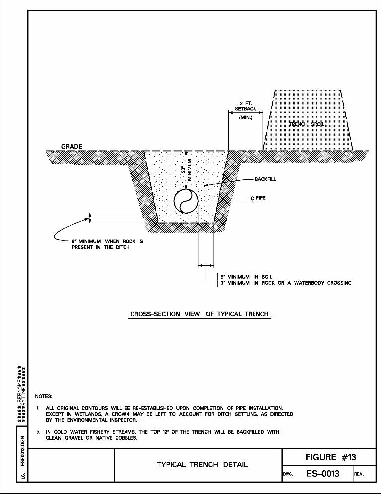
8" MINIMUM WHEN ROCK IS PRESENT IN THE DITCH
2 FT. SETBACK
(MIN.)
-.- <[,_I'IPE_
6" MINIMUM IN SOIL 9" MINIMUM IN ROCK OR A WATERBODY CROSSING
CROSS-SECTION VIEW OF TYPICAL TRENCH
1. ALL ORIGINAL CONTOURS WILL BE RE-ESTABLISHED UPON COMPLETION OF PIPE INSTALLATION. EXCEPT IN WETLANDS, A CROWN MAY BE LEFT TO ACCOUNT FOR DITCH SETTLING, AS DIRECTED BY THE ENVIRONMENTAL INSPECTOR.
2. IN COLD WATER FISHERY STREAMS, THE TOP 12" OF THE TRENCH WILL BE BACKFILLED WITH CLEAN GRAVEL OR NATIVE COBBLES. g
i~------------~------------------------~----FI_G_U_R_E_#-1-3--~
!3 TYPICAL TRENCH DETAIL DWG. ES-0013 REV.

[Y)
~ ~N L'QN LN 3'-3---<Sl
z t!l c
TEMPORARY EROSION CONTROL (DRIVEABLE BERMS, STRAW BALES)
EQUIPMENT CROSSING
TRAVEL LANE
TEMPORARY INTERCEPTOR DIKE (AS NECESSARY)
. I . I . ~INSTALL SEDIMENT BARRIER
(AS NECESSARY)
NOTES:
I . . I . ' I . .
I
I . ' I . i . I
PLAN VIEW
I EQUIPMENT PAD ~4"- 6" (AVG.) CRUSHED STONE
SECTION "A-A"
1.@ TEMPORARY SEDIMENT BARRIER OF SILT FENCE ANIYOR STRAW BALES, OR OTHER APPROPRIATE MATERIAL
2. ADDITIONAL EQUIPMENT PADS CAN BE PUT SIDE BY SIDE IF EXTRA WIDTH IS REQUIRED.
3. EQUIPMENT PAD TYPICALLY CONSTRUCTED OF HARDWOOD; MUST ACCOMMODATE THE LARGEST EQUIPMENT USED.
4. CRUSHED STONE MUST EXTEND A MINIMUM OF 10 FEET FROM THE TOP OF THE BANK.
5. CONSTRUCT BRIDGE TO PREVENT SOIL FROM ENTERING WATERBODY.
§ r----------------------,--------------------------------------------~r------------------------; ~ TEMPORARY EQUIPMENT BRIDGE FIGURE #27
(EQUIPMENT PADS AND CULVERTS) DWG. ES-0027 REV.

[Y)
~ ~N L'QN LN 3'-3---<Sl
z t!l c
TEMPORARY EROSION CONTROL (DRIVEABLE BERMS, STRAW BALES)
I TEMPORARY INTERCEPTOR DIKE (AS NECESSARY)
FLUME PIPES
I . I . I .
I ' ' I
' I ' I
I . I . I
I
i
PLAN VIEW
I . . I . I . I
I . I . I
(AVG.) CRUSHED STONE
""""' ......... EQUIPMENT ; ; ;;;;; CROSSING
. . . . . . . ~-,,......,--,
NOTES:
;< ;:·k: ;:::· <··lr\it\it\0~:Q'~t~:\9~::7;·:.<:: ;< ;< : -~---~: -~~A'=Y'~~uLv:-~~-u-.: .~~-~: ·
STREAM _j ·~ .·•·. •·, ... •· .·• . ··' .·• . ····.· .·•·'.·· .. ·•· . CHANNEL
SECTION "A-A"
1. ALIGN FLUME PIPES TO PREVENT EROSION AND STREAMBED SCOUR.
2. ® TEMPORARY SEDIMENT BARRIER OF SILT FENCES ANOIOR STRAW BALES, OR OTHER APPROPRIATE MATERIALS.
§ r-------------------~----------------------------------------~----------------------~ ~ TEMPORARY EQUIPMENT BRIDGE FIGURE #28 w
(CRUSHED STONE AND CULVERTS) ES-0028 REV. DWG.
[Y)
~ ~N L'QN LN 3'-3---<Sl
z C)
0
FLOW
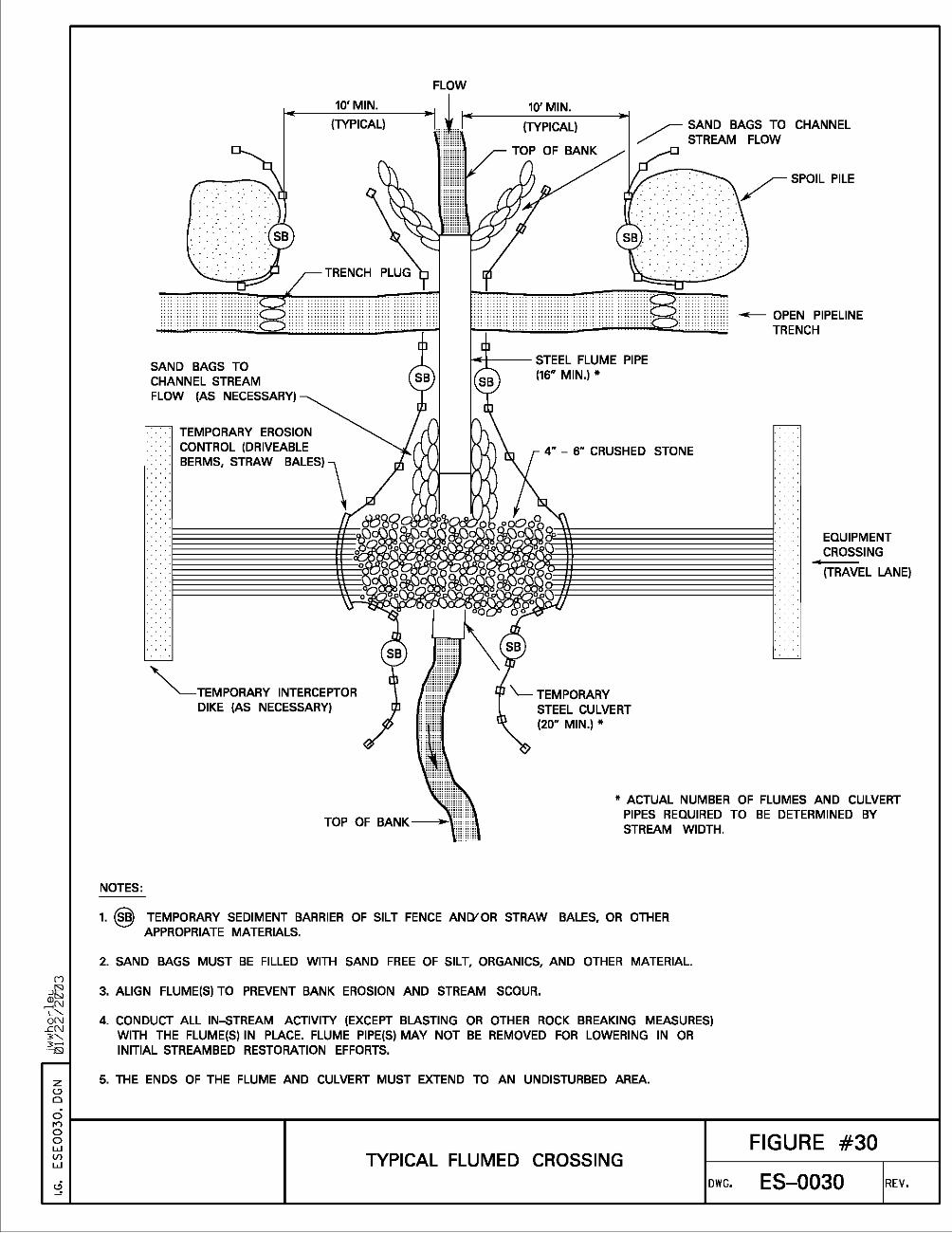
10' MIN. 10' MIN. (TYPICAL) (TYPICAL) ~ SAND BAGS TO CHANNEL
/ STREAM FLOW
SAND BAGS TO CHANNEL STREAM FLOW (AS NECESSARY)
TEMPORARY EROSION CONTROL (DRIVEABLE BERMS, STRAW BALES)
"'----TEMPORARY INTERCEPTOR DIKE (AS NECESSARY)
~-- STEEL FLUME PIPE (16" MIN.)*
4" - 6" CRUSHED STONE
\___TEMPORARY STEEL CULVERT (20" MIN.)*
SPOIL PILE
- OPEN PIPELINE TRENCH
EQUIPMENT CROSSING
(TRAVEL LANE)
* ACTUAL NUMBER OF FLUMES AND CULVERT PIPES REQUIRED TO BE DETERMINED BY STREAM WIDTH.
NOTES:
1. @ TEMPORARY SEDIMENT BARRIER OF SILT FENCE ANDfOR STRAW BALES, OR OTHER APPROPRIATE MATERIALS.
2. SAND BAGS MUST BE FILLED WITH SAND FREE OF SILT, ORGANICS, AND OTHER MATERIAL.
3. ALIGN FLUME(S) TO PREVENT BANK EROSION AND STREAM SCOUR.
4. CONDUCT ALL IN-STREAM ACTIVITY (EXCEPT BLASTING OR OTHER ROCK BREAKING MEASURES) WITH THE FLUME(S) IN PLACE. FLUME PIPE(S) MAY NOT BE REMOVED FOR LOWERING IN OR INITIAL STREAMBED RESTORATION EFFORTS.
5. THE ENDS OF THE FLUME AND CULVERT MUST EXTEND TO AN UNDISTURBED AREA.
gr----------------------,--------------------------------------------~r------------------------; 0 0 w Vl w TYPICAL FLUMED CROSSING
DWG.
FIGURE #30
ES-0030 REV.

[Y)
10'
MIN.
~SPARE PUMP
......,__SPILL CONTAINMENT DEVICE
SPOIL PILE
~OPEN PIPELINE / TRENCH
~ "'"" ><UG
SANDBAG DAM
STREAM
SECTION "A-A"
NOTES:
A EQUIPMENT CROSSING
~ TEMPORARY EROSION CONTROL (DRIVEABLE BERMS, STRAW BALES)
4" - 6" STONE FILL
1.@ TEMPORARY SEDIMENT BARRIER OF SILT FENCE ANIYOR STRAW BALES, OR OTHER APPROPRIATE MATERIALS
2. INSTALL AND SEAL SANDBAGS UPSTREAM AND DOWNSTREAM OF THE CROSSING.
3. CREATE AN UPSTREAM SUMP USING SANDBAGS IF NATURAL SUMP IS UNAVAILABLE FOR THE INTAKE HOSE.
4. EXCAVATE ACROSS STREAM CHANNEL FOLLOWING WATER REROUTING.
~ 5. DO NOT REFUEL OR STORE FUEL WITHIN 100 FEET OF THE WATERBODY, WHERE FEASIBLE. ~N
6~ 6. MONITOR PUMPS AT ALL TIMES DURING STREAM CROSSING PROCEDURE . .eN 3'-. .";S) 7. USE SUFFICIENT PUMPS, INCLUDING ONSITE BACKUP PUMPS, TO MAINTAIN DOWNSTREAM FLOW.
8. SCREEN PUMP INTAKES.
z 8 9. NUMBER OF FLUME PIPES FOR EQUIPMENT BRIDGE WILL VARY DEPENDING ON SITE CONDITIONS.
~ r----------------------,--------------------------------------------~r------------------------;
~ TYPICAL DAM AND PUMP FIGURE #31 w
DWG. ES-0031 REV. CROSSING