Embed Size (px)
Citation preview

PTFR-NHigh Current Bushings 36 kV up to 36 kA
BUSHINGS
1
Customer Benefits • Bushings with longer lifetime and higher reliability • No performance reduction with age • Partial discharge free
GRID
OIL-TO-AIR - Resin Impregnated PaperHigh Current - IEC and IEEE Standards
PTFR-N are capacitance graded bushings with resin impregnated paper insulation. They are designed for use on power transformers, installed in any position, in compliance with the latest edition of IEC 60137 and IEEE C57.19.01 - 2000. Design, components and manufacturing technology guarantee an average life time longer than 30 years under normal operating conditions.
Manufacturing of capacitance graded bushings
The main electrical component is the condenser body that is manufactured using resin-impregnated paper technology.
This technology utilizes a continuous sheet of pure crepe paper, wound around a support tube. During the winding process, the first step is to reduce its water content to a minimum by drying the paper with heated cylinders and infrared rays. During winding, a series of aluminum foils are coaxially inserted between the layers of the paper in order to grade the best possible distribution of radial and longitudinal electrical gradients between the central conductor and the grounded flanges.
The bushing is designited as follows:PTFR-N.36-200-10000
PTFR-N Condenser bushings for use on transformer, High Current, Resign impregnated Paper (RIP) technology
36 Rated voltage (kV)
200 BIL (Basic Insulation Level) in kV
10000 Rated Current (A)
AN ALSTOM COMPANY
The winding and foil placement is made by computer-controlled machines. After winding, each condenser core is placed into an autoclave for resin impregnation under vacuum. Each core is then machined to achieve the final shape.

CONDENSER BUSHINGS PTFR-N
2
1. Dry filling2. Condenser body 3. Porcelain insulator4. Flange
Air side
The air side envelope is made of brown colored porcelain. The creepage distance is for a very high polluted atmosphere (VHP) equivalent to 31 mm/kV. The shed configuration is alternate-type (small-large sheds). This is the most effective solution, proven by salt tests and the profile of sheds complies with the recommendations of IEC 60815.
The air extremity of the bushing inner conductor is provided by two or more palms for the connections of the bus bars, which are normally enclosed in a metal clad duct.
Oil side
The condenser body is immersed in the transformer oil and is hermeti-cally sealed to the flange. The springs, located on the oil side, are used for mechanical coupling of all bushings parts and to avoid shifting due to the thermal variations. The oil extremity of the inner conductor is provided with one or more palms for the connection to the transformer windings.
Current ratings
The acceptable operating currents versus oil temperatures and busduct air compared to conductor can be calculated using the following formula:
Ina = In x α x b
where: Ina continuous admissible current [A]In nominal bushing current [A] α temperature coefficientb CT space coefficient
α and ß can be determined using the tables here below, where:Tc admissible conductor temperature (120°C) E classTa ambient (bus duct) air temperature (°C)To transformer oil temperature (°C)K CT space (mm)
Conductor and terminals
Both sides of the conductor and terminals are made from a unique cast aluminum alloy, which has an IACS 55% conductivity.
Terminal surfaces are not treated. Upon request it is possible to provide them with 10 micron silver plating.
Fig. 1: Section
Main featuresPTFR: Resin Impregnated Paper High current IEC Standards
Rated voltages: 36 kV
Air side: porcelain insulator
Oil side: Resin Impregnated Paper winding
Inner conductor made of cast aluminum
Dry filling of the interspace between porcelain and condenser body
Installation in any position
Flange of aluminum alloy casting
Maximum current rating up to 36.000 A
Flange provided with power factor tap and Buchholz relay connection
1
2
3
4

CONDENSER BUSHINGS PTFR-N
3
Fig. 2: Power factor tap
1. Measurement electrode2. Insulating bushing3. Tap body4. Gasket5. Closing and grounding cap
2 53 4
1
ø 8 mm
Flange
The flange is made from cast aluminum, and is equipped with lifting holes, a power factor tap (can withstand 3 kV for 60 s) (fig. 2) and Buchholz relay connection (1/2” gas outlet plug) (fig. 6).
Flange surface treatment
Power factor tap surface finish avoids any corrosion throughout lifetime and allows for easy screwing and unscrewing in service. Further finishing or final painting are the customer’s option.
Assembling
The coupling between porcelains and metal parts (flange and inner conductor) is achieved with belleville washer-type springs, placed in the oil side of the bushings.
Gaskets
Made of Viton® a fluorocarbon rubber elastomer (FPM), o-ring type. They are compatible with all the fluids they are in contact with (transformer mineral oil). Air side gaskets are carefully protected, by means of a sealing, against influence of polluting weather elements. For special requirements, such as low ambient temperatures (down to -55°C), special o-rings are used.
Dry filling
PTFE bushings can be installed in any position because the interspace between porcelain and condenser body is filled with a dry mass (polyurethane).
This material offers:
Low dielectric losses Good level of partial discharges Good thermal resistance Constant characteristics versus time
Dry filling improves reliability in comparison with oil filled type and makes installation simpler: no oil leakage and, if horizontal instal-lation, no oil reservoir.
Tests
All bushings have electrical characteristics that are tested in compliance with the last edition of CEI IEC 60137-Publication INSULATED BUSH-INGS FOR ALTERNATING VOLTAGES ABOVE 1000 V, and Main National Standards.
Name plate
Each bushing is provided with a name plate, (fig. 4) with all the electrical data and serial number, in accordance with the prescription of IEC Stand-ards. The stainless steel plate is placed on the flange by rivets.
Tc - Ta (°C) Coefficient α (36 kV TYPE)90 0.76 0.83 0.92 0.99 1.0680 0.72 0.79 0.88 0.96 1.0370 0.67 0.76 0.85 0.93 1.0160 0.63 0.73 0.82 0.91 1.0050 0.59 0.70 0.79 0.89 0.9940 0.55 0.66 0.76 0.86 0.9630 0.50 0.63 0.73 0.84 0.9520 0.46 0.59 0.70 0.81 0.9310 0.43 0.56 0.67 0.79 0.91
Tc - T0 (°C) 10 20 30 40 50
CT space Coefficient bK (mm) 24 kV TYPE 36 kV TYPE
Ta = 40°C Ta = 80°C Ta = 40°C Ta = 80°C0 1.00 1.00 1.00 1.00
100 0.94 0.99 0.97 0.99200 0.87 0.97 0.90 0.95300 0.81 0.95 0.84 0.91400 0.75 0.91 0.79 0.87500 0.68 0.87 0.75 0.83600 0.61 0.81 - -700 0.55 0.75 - -
PASSANTE-BUSHING-TRAVERSEE-DURCHFUHRUNG
50-60Hz
A
MILANI TA LY
Kg
kV
N°1873
654
2
Fig. 4: Nameplate
Fig. 3: PTFR-N dimensions
1. Bushing type2. Insulating voltage3. Rated current 4. Max. mounting angle
off of the vertical5. Weight6. Blank (available) 7. Serial number8. Month - year of final tests
CONDENSER BUSHINGS PTFR-N
Grid
-ITR-
Bush
ings
-L3-
PTFR
-N-7
2321
-201
1_10
-EN
- ©
- Al
stom
Grid
- 20
08. A
lsto
m G
rid, t
he A
lsto
m G
rid lo
go a
nd a
ny a
ltern
ativ
e ve
rsio
n th
ereo
f are
trad
emar
ks a
nd se
rvic
e m
arks
of A
lsto
m G
rid. A
ll tr
ade
nam
es o
r tra
dem
arks
men
tione
d he
rein
whe
ther
regi
ster
ed o
r no
t, ar
e th
e pr
oper
ty o
f the
ir ow
ners
. - 3
8919
1982
RCS
PAR
IS O
ur p
olic
y is
one
of c
ontin
uous
dev
elop
men
t. Ac
cord
ingl
y th
e de
sign
of o
ur p
rodu
cts
may
cha
nge
at a
ny ti
me.
Whi
lst e
very
effo
rt is
mad
e to
pro
duce
up
to d
ate
liter
atur
e, th
is b
roch
ure
shou
ld o
nly
be re
gard
ed
as a
gui
de a
nd is
inte
nded
for i
nfor
mat
ion
purp
oses
onl
y. Its
cont
ents
do
not c
onst
itute
an
offe
r for
sale
or a
dvis
e on
the
appl
icat
ion
of a
ny p
rodu
ct re
ferr
ed to
in it
. We
cann
ot b
e he
ld re
spon
sibl
e fo
r any
relia
nce
on a
ny d
ecis
ions
take
n on
its c
onte
nts w
ithou
t spe
cific
adv
ice.
Alstom Grid Worldwide Contact Centre www.grid.alstom.com/contactcentre Tel.: +44 (0) 1785 250 070 www.grid.alstom.com
GRID
To contact the manufacturerViale Suzzani, 229 20162 MILANO (Italy)Tel: +39 02 661 221Fax: +39 02 647 09 06Email: [email protected]
Following the acquisition of PASSONI & VILLA, Alstom Grid now offers a large portfolio of condenser bushings for AC or DC operation. If you require any further information, please address your queries to
[email protected] ALSTOM COMPANY
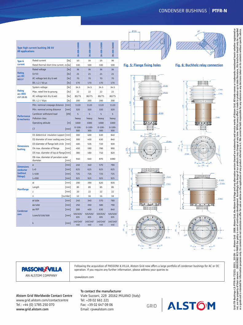
Type high current bushing 36 kV All applications
36-2
00-1
0000
36-2
00-1
6000
36-2
00-2
5000
36-2
00-3
6000
Type & current
Rated current [ka] 10 16 25 36
Rated thermal short time current, 2s [ka] 100 100 100 100
Rating acc.IEC 60137
Rated voltage [kv] 36 36 36 36
Ur/√3 [kv] 21 21 21 21
AC voltage test dry & wet [kv] 70 70 70 70
BIL 1.2 / 50 μs [kv] 170 170 170 170
Rating acc.IEEE c57.19.01
System voltage [kv] 34.5 34.5 34.5 34.5
Max. rated line to groung [kv] 22 22 22 22
AC voltage test dry & wet [kv] 80/75 80/75 80/75 80/75
BIL 1,2 / 50μs [kv] 200 200 200 200
Performance & mechanics
Min. nominal creepage distance [mm] 1120 1120 1120 1120
Min. nominal arcing distance [mm] 320 320 320 320
Cantilever withstand load [kN] 5 5 5 5
Pollution class heavy heavy heavy heavy
Operating attitude [m] 1000 1000 1000 1000
CT [mm] 0-100-300
0-100-300
0-100-300
0-100-300
Dimensions bushing
D1 dielectrical insulation support [mm] 300 400 630 840
D2 diameter of inner sealing area [mm] 300 400 630 840
D3 diameter of flange bolt circle [mm] 400 535 720 930
D4 max. diameter of flange [mm] 450 590 780 990
D5 max. diameter of top al-flange [mm] 380 480 710 920
D6 max. diameter of porcelain outer diameter [mm] 540 640 870 1080
Dimensions conductor (without fittings)
ø [mm] 240 340 570 780
L=0 [mm] 625 625 625 625
L=100 [mm] 725 725 725 725
L=300 [mm] 925 925 925 925
Mainflange
øi [mm] 290 390 620 830
Length [mm] 85 85 85 85
z [mm] 20 22 22 22
n [number] 12 16 16 16
Condenser core
øi tube [mm] 240 340 570 780
øa tube [mm] 250 350 580 790
øa RIP [mm] 300 400 630 840
Lcore/0/100/300 [mm] 535/635/ 835
535/635/ 835
535/635/ 835
535/635/ 835
k [mm] 140/240/ 440
140/240/ 440
140/240/ 440
140/240/ 440
Fig. 5: Flange fixing holes Fig. 6: Buchholz relay connection
Ø 20 45°
M12
1021
1055
840
125
808
140
8532
014
0
L.TO
T.
20 460 20
500
36°
290
25
710
R260
240
R127.5
170
125
80
K14
085
320
140
481
515
300
L. T
OT.
120
25
20020 20
380
240
45°
515
811
845
140
320
8514
0K
8012
5
L.TO
T
20 460 20
500
36°
290
25
710
R260
240
L.TO
T.
140
85K
581
400
80
615
125
320
140
25
20 200 20
240
R127.5480
170
45°
120