Embed Size (px)
Citation preview
SIEMENS PSS SINCAL File Formats
October 2019 1/64
PSS®SINCAL File Formats
October 2019
This document contains detailed descriptions of formats for different PSS SINCAL files. These files are used
to exchange data for input data, results and graphics with external programs.
1 PSS SINCAL PIC File 4
1.1 Structure of the PSS SINCAL PIC File 4
1.1.1 Example of a PSS SINCAL PIC File 4
1.1.2 HEADER 4
1.1.3 LAYER 5
1.1.4 COLOR 6
1.1.5 VTXT – Graphic Text 7
1.1.6 PLIN – Polyline 9
1.1.7 POL – Polygon 10
1.1.8 KRE – Circle or Ellipse 12
1.1.9 RHOMB – Rectangle or Diamond 13
1.1.10 PIE – Arc of a Circle or Circle Segment 14
1.1.11 GRP_START/GRP_END – Groups 16
1.2 Help Program VecToPic 16
1.2.1 Starting VecToPic from the Graphic User Interface 17
1.2.2 Starting VecToPic with a Command Prompt 18
1.2.3 Integrating PIC Files into PSS SINCAL 19
2 PSS SINCAL Symbol Files 20
2.1 General Remarks 20
2.1.1 Storage Locations for User-Defined Symbol Files 20
2.2 Example for the Symbol File 21
2.3 Symbols for Network Elements 22
2.3.1 Pre-Defined Sections for Element Symbols 22
2.3.2 Symbol Definition for Network Elements 22
2.3.3 Terminal Section 23
2.3.4 Predefined Sections for Additional Element Symbols 23
2.3.5 Overlay Section 24
2.4 Drawing Command 24
SIEMENS PSS SINCAL File Formats
October 2019 2/64
2.4.1 Base Attributes 25
2.4.2 Fill Pattern 25
2.4.3 Line 25
2.4.4 Rectangle 25
2.4.5 Ellipse 26
2.4.6 Circular Arc 26
2.4.7 Circular Sector 27
2.4.8 Polyline 27
2.4.9 Polygon 28
2.4.10 Text 28
2.4.11 Dynamic Text 28
2.4.12 Overlay 28
3 PSS SINCAL Diagrams as an XML File 30
3.1 Structure of the XML File 30
3.1.1 Document 31
3.1.2 Diagram 32
3.1.3 Graph 32
3.1.4 Series 33
3.2 Predefined Types 34
3.2.1 Types for Diagrams 34
3.2.2 Types for Graphs/Characteristic Curves 35
3.2.3 Special Types for Specific Characteristic Curves 36
4 Network State/Network Graphics and Scenario File as an XML File 41
4.1 Structure of the XML File 41
4.1.1 Document 43
4.1.2 Settings 43
4.1.3 NetworkData 44
4.1.4 Node 44
4.1.5 Element 45
4.1.6 SwitchState 46
4.1.7 Switch 46
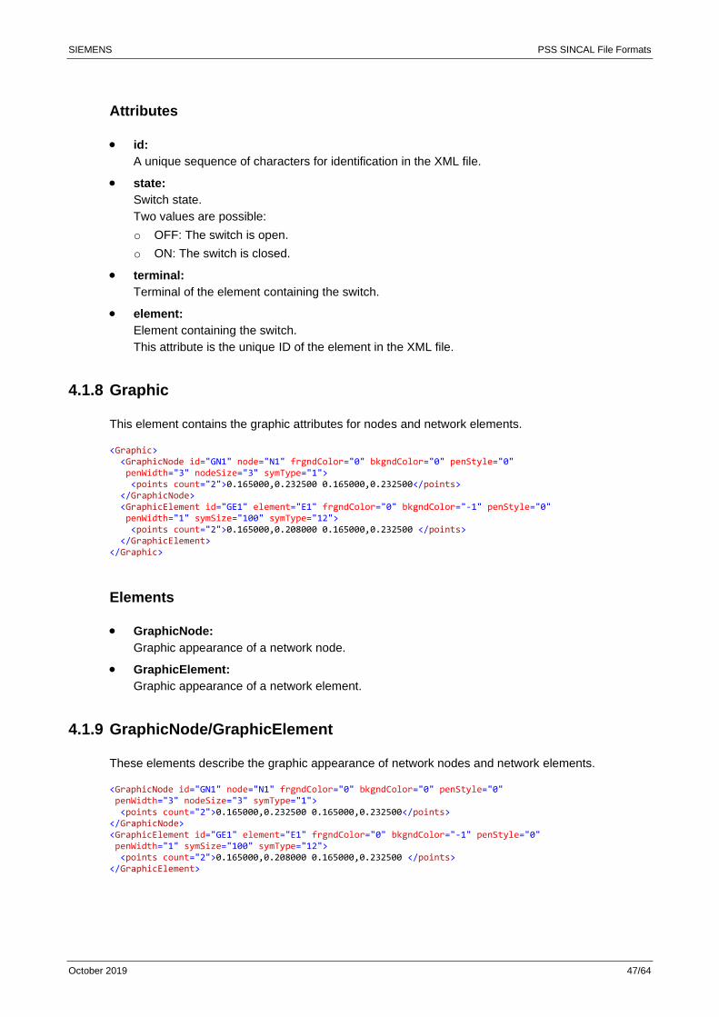
4.1.8 Graphic 47
4.1.9 GraphicNode/GraphicElement 47
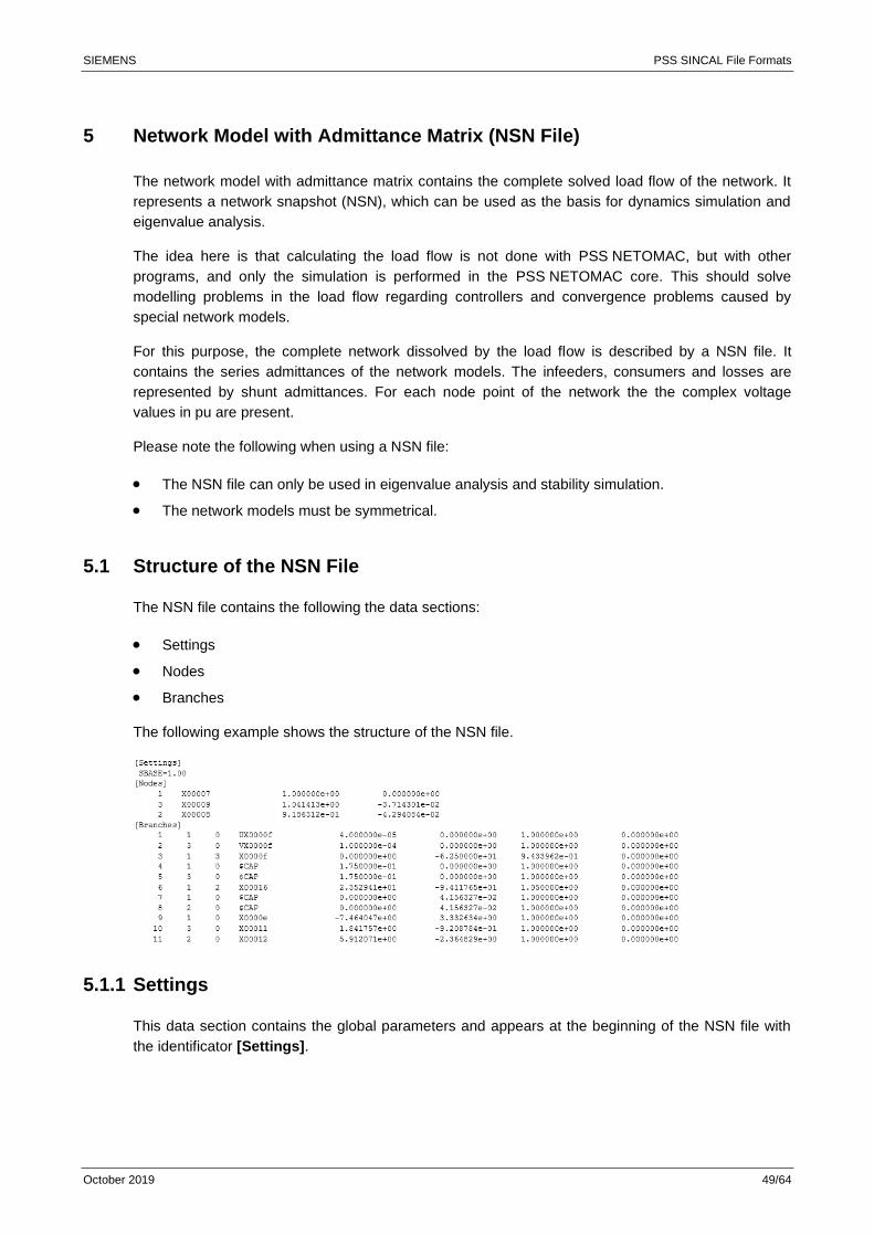
5 Network Model with Admittance Matrix (NSN File) 49
5.1 Structure of the NSN File 49
5.1.1 Settings 49
SIEMENS PSS SINCAL File Formats
October 2019 3/64
5.1.2 Nodes 50
5.1.3 Branches 50
5.2 Using the NSN File 50
6 Reliability Results in the XML Database 52
6.1 Structure of the XML Database 52
6.1.1 Reliability 53
6.1.2 Date 53
6.1.3 Info 54
6.1.4 Outage 54
6.1.5 Elem, Node, Load 55
6.1.6 Result 56
6.1.7 Event 57
7 Optimal Network Structure Results in the XML Database 59
7.1 Structure of the XML Database 59
7.1.1 OptNetResults 60
7.1.2 General 60
7.1.3 Combination 60
7.1.4 Route 62
7.1.5 Closure 63
7.1.6 Object 63
7.1.7 Node 63
7.1.8 Branch 64
7.1.9 Calculation Results 64
SIEMENS PSS SINCAL File Formats
October 2019 4/64
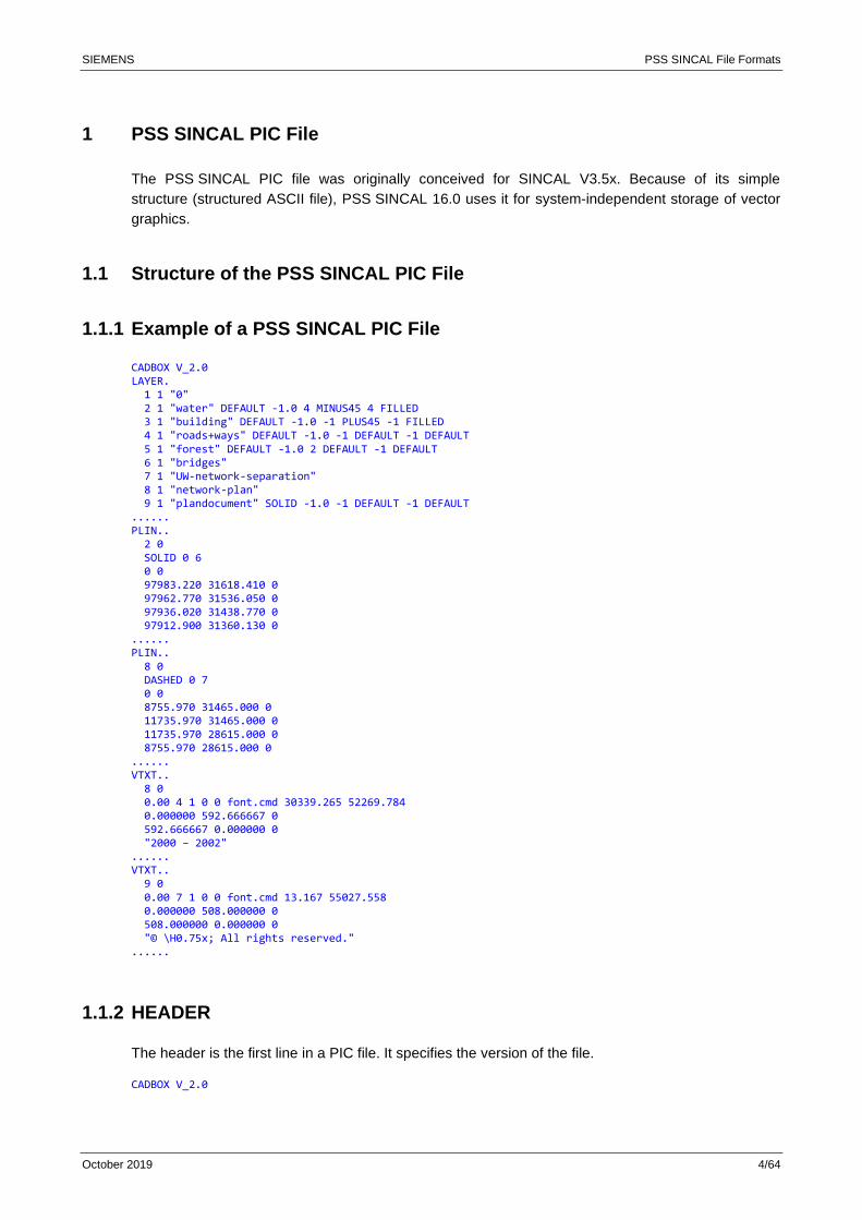
1 PSS SINCAL PIC File
The PSS SINCAL PIC file was originally conceived for SINCAL V3.5x. Because of its simple
structure (structured ASCII file), PSS SINCAL 16.0 uses it for system-independent storage of vector
graphics.
1.1 Structure of the PSS SINCAL PIC File
1.1.1 Example of a PSS SINCAL PIC File
CADBOX V_2.0 LAYER. 1 1 "0" 2 1 "water" DEFAULT -1.0 4 MINUS45 4 FILLED 3 1 "building" DEFAULT -1.0 -1 PLUS45 -1 FILLED 4 1 "roads+ways" DEFAULT -1.0 -1 DEFAULT -1 DEFAULT 5 1 "forest" DEFAULT -1.0 2 DEFAULT -1 DEFAULT 6 1 "bridges" 7 1 "UW-network-separation" 8 1 "network-plan" 9 1 "plandocument" SOLID -1.0 -1 DEFAULT -1 DEFAULT ...... PLIN.. 2 0 SOLID 0 6 0 0 97983.220 31618.410 0 97962.770 31536.050 0 97936.020 31438.770 0 97912.900 31360.130 0 ...... PLIN.. 8 0 DASHED 0 7 0 0 8755.970 31465.000 0 11735.970 31465.000 0 11735.970 28615.000 0 8755.970 28615.000 0 ...... VTXT.. 8 0 0.00 4 1 0 0 font.cmd 30339.265 52269.784 0.000000 592.666667 0 592.666667 0.000000 0 "2000 – 2002" ...... VTXT.. 9 0 0.00 7 1 0 0 font.cmd 13.167 55027.558 0.000000 508.000000 0 508.000000 0.000000 0 "© \H0.75x; All rights reserved." ......
1.1.2 HEADER
The header is the first line in a PIC file. It specifies the version of the file.
CADBOX V_2.0
SIEMENS PSS SINCAL File Formats
October 2019 5/64
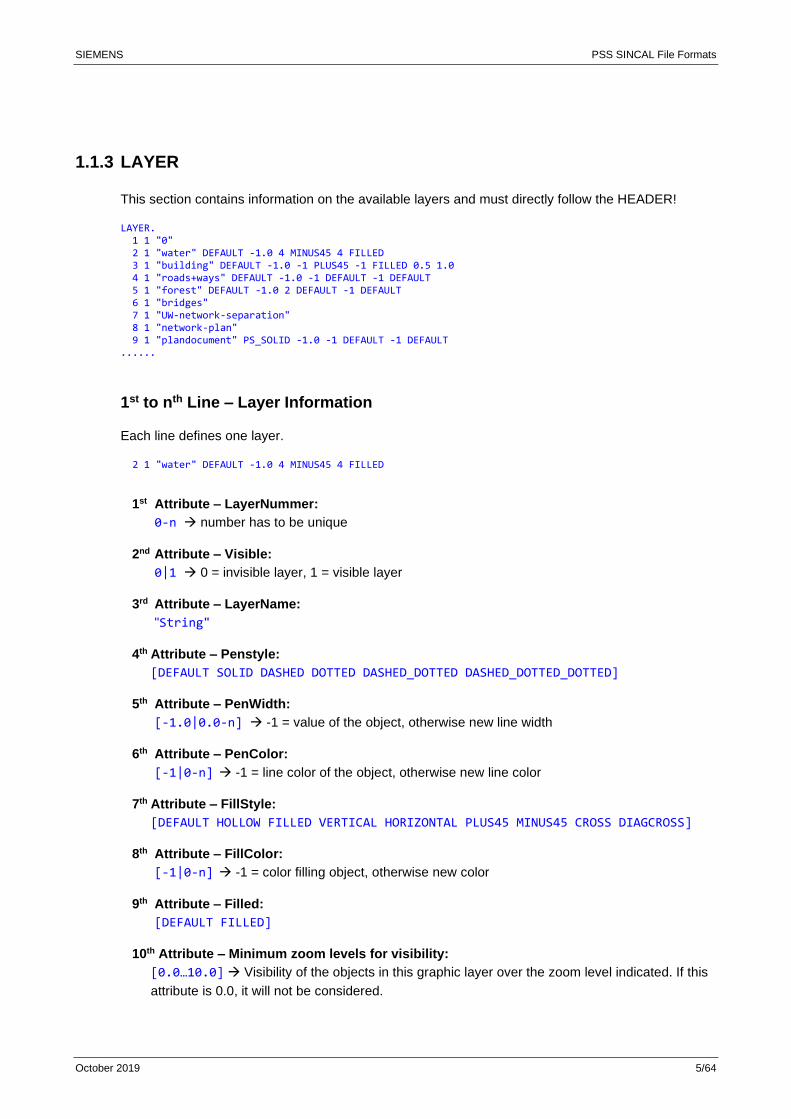
1.1.3 LAYER
This section contains information on the available layers and must directly follow the HEADER!
LAYER. 1 1 "0" 2 1 "water" DEFAULT -1.0 4 MINUS45 4 FILLED 3 1 "building" DEFAULT -1.0 -1 PLUS45 -1 FILLED 0.5 1.0 4 1 "roads+ways" DEFAULT -1.0 -1 DEFAULT -1 DEFAULT 5 1 "forest" DEFAULT -1.0 2 DEFAULT -1 DEFAULT 6 1 "bridges" 7 1 "UW-network-separation" 8 1 "network-plan" 9 1 "plandocument" PS_SOLID -1.0 -1 DEFAULT -1 DEFAULT ......
1st to nth Line – Layer Information
Each line defines one layer.
2 1 "water" DEFAULT -1.0 4 MINUS45 4 FILLED
1st Attribute – LayerNummer:
0-n → number has to be unique
2nd Attribute – Visible:
0|1 → 0 = invisible layer, 1 = visible layer
3rd Attribute – LayerName:
"String"
4th Attribute – Penstyle:
[DEFAULT SOLID DASHED DOTTED DASHED_DOTTED DASHED_DOTTED_DOTTED]
5th Attribute – PenWidth:
[-1.0|0.0-n] → -1 = value of the object, otherwise new line width
6th Attribute – PenColor:
[-1|0-n] → -1 = line color of the object, otherwise new line color
7th Attribute – FillStyle:
[DEFAULT HOLLOW FILLED VERTICAL HORIZONTAL PLUS45 MINUS45 CROSS DIAGCROSS]
8th Attribute – FillColor:
[-1|0-n] → -1 = color filling object, otherwise new color
9th Attribute – Filled:
[DEFAULT FILLED]
10th Attribute – Minimum zoom levels for visibility:
[0.0…10.0] → Visibility of the objects in this graphic layer over the zoom level indicated. If this
attribute is 0.0, it will not be considered.
SIEMENS PSS SINCAL File Formats
October 2019 6/64
11th Attribute – Maximum zoom levels for visibility:
[0.0…10.0] → Visibility of the objects in this graphic layer up to the zoom level indicated. If this
attribute is 0.0, it will not be considered.
Attributes 1-3 (layer number, visible, layer name) are required; the other attributes are optional.
These attributes are assigned to all graphic elements assigned to this layer. This allows you to
overwrite individual attributes of the graphic elements globally.
Examples
Color all objects of the “water” layer blue, set the pattern to MINUS45 and fill the pattern:
2 1 "water" DEFAULT -1.0 4 MINUS45 4 FILLED
Assign the fill pattern PLUS45 to all objects of the “building” layer and fill the objects:
3 1 "building" DEFAULT -1.0 -1 PLUS45 -1 FILLED
Set all objects of the “plandocument” layer PenStyle to SOLID:
9 1 "plandocument" PS_SOLID -1.0 -1 DEFAULT -1 DEFAULT
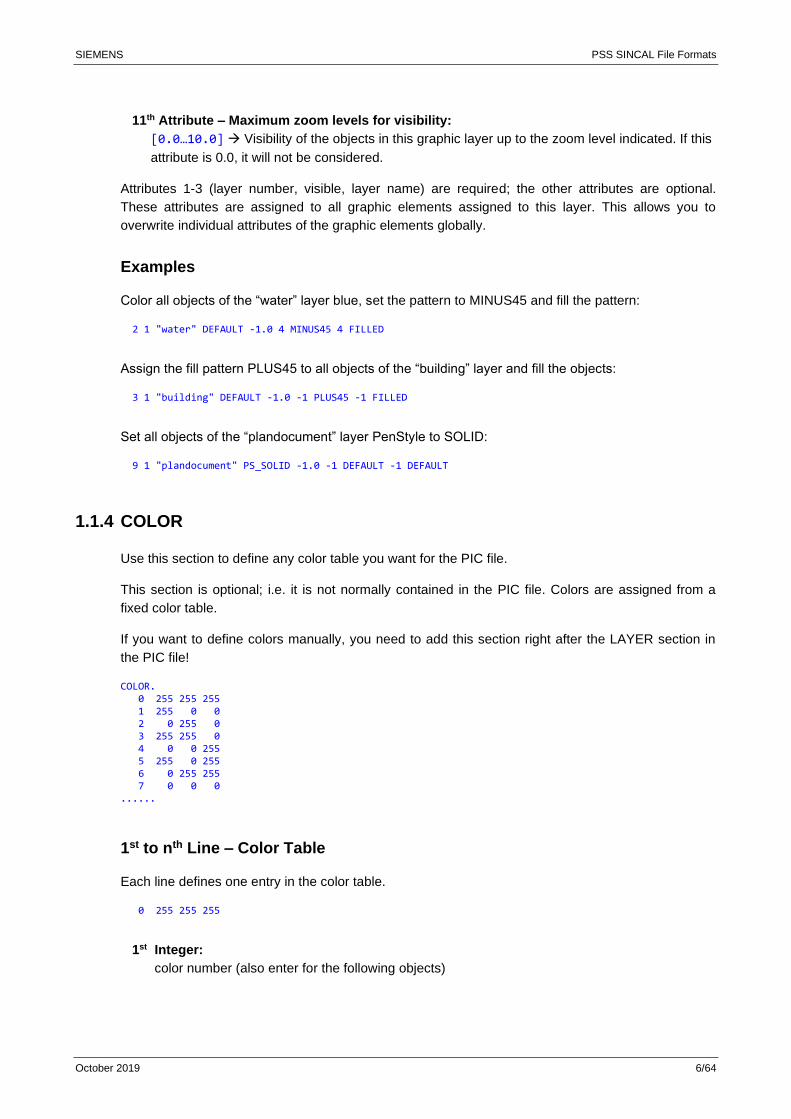
1.1.4 COLOR
Use this section to define any color table you want for the PIC file.
This section is optional; i.e. it is not normally contained in the PIC file. Colors are assigned from a
fixed color table.
If you want to define colors manually, you need to add this section right after the LAYER section in
the PIC file!
COLOR. 0 255 255 255 1 255 0 0 2 0 255 0 3 255 255 0 4 0 0 255 5 255 0 255 6 0 255 255 7 0 0 0 ......
1st to nth Line – Color Table
Each line defines one entry in the color table.
0 255 255 255
1st Integer:
color number (also enter for the following objects)
SIEMENS PSS SINCAL File Formats
October 2019 7/64
2nd Integer:
amount of red in the color (0-255)
3rd Integer:
amount of green in the color (0-255)
4th Integer:
amount of blue in the color (0-255)
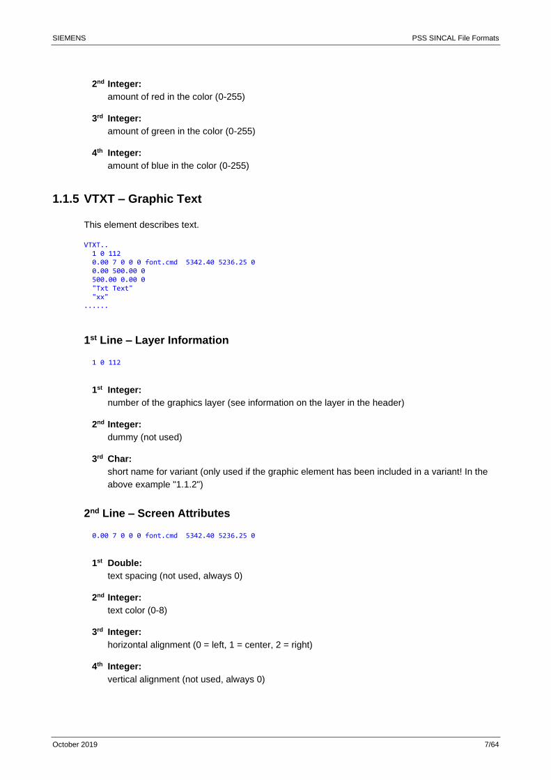
1.1.5 VTXT – Graphic Text
This element describes text.
VTXT.. 1 0 112 0.00 7 0 0 0 font.cmd 5342.40 5236.25 0 0.00 500.00 0 500.00 0.00 0 "Txt Text" "xx" ......
1st Line – Layer Information
1 0 112
1st Integer:
number of the graphics layer (see information on the layer in the header)
2nd Integer:
dummy (not used)
3rd Char:
short name for variant (only used if the graphic element has been included in a variant! In the
above example "1.1.2")
2nd Line – Screen Attributes
0.00 7 0 0 0 font.cmd 5342.40 5236.25 0
1st Double:
text spacing (not used, always 0)
2nd Integer:
text color (0-8)
3rd Integer:
horizontal alignment (0 = left, 1 = center, 2 = right)
4th Integer:
vertical alignment (not used, always 0)

SIEMENS PSS SINCAL File Formats
October 2019 8/64
5th Integer:
??
6th Char:
name of selected vector font (for SINCAL V3.5x, not considered in PSS SINCAL 16.0)
7th Double:
x position in area [m]
8th Double:
y position in the area [m]
9th Integer:
dummy (not used)
3rd Line – Text Vector Height
0.00 500.00 0
1st Double:
vector – x content [m]
2nd Double:
vector – y content [m]
3rd Integer:
dummy (not used)
The actual text height is calculated from the vectors as follows:
double vtext_height( cadObject *o ) { double height = (SQARE( o->typ.vtxt.ch.x ) + SQARE( o->typ.vtxt.ch.y )); height = sqrt( ABS(height) ); return height; }
4th Line – Text Vector Width
500.00 0.00 0
1st Double:
vector – x content [m]
2nd Double:
vector – x content [m]
3rd Integer:
dummy (not used)
SIEMENS PSS SINCAL File Formats
October 2019 9/64
5th to nth Line – Text Lines
"Txt Text" "xx"
These lines contain the text to be actually displayed.
Comments
The text position is the bottom of the first text line and not the upper left fixing point of the rectangle
around it.
The text vector – height and text vector – width also precisely determine the rotation and slant of
the text.
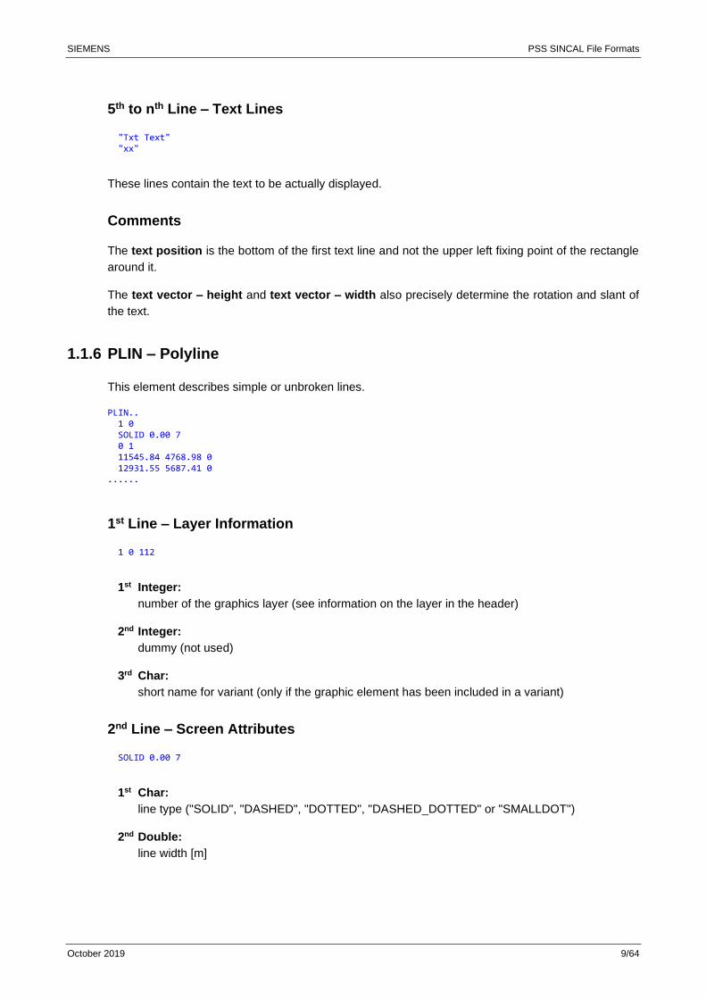
1.1.6 PLIN – Polyline
This element describes simple or unbroken lines.
PLIN.. 1 0 SOLID 0.00 7 0 1 11545.84 4768.98 0 12931.55 5687.41 0 ......
1st Line – Layer Information
1 0 112
1st Integer:
number of the graphics layer (see information on the layer in the header)
2nd Integer:
dummy (not used)
3rd Char:
short name for variant (only if the graphic element has been included in a variant)
2nd Line – Screen Attributes
SOLID 0.00 7
1st Char:
line type ("SOLID", "DASHED", "DOTTED", "DASHED_DOTTED" or "SMALLDOT")
2nd Double:
line width [m]
SIEMENS PSS SINCAL File Formats
October 2019 10/64
3rd Integer:
line color (0-8)
3rd Line – Visibility (Dummy)
0 1
1st Integer:
dummy (not used)
2nd Integer:
element visibility (de facto always "1")
4th to nth Line – Definition Points
11545.84 4768.98 0 12931.55 5687.41 0
1st Double:
x position [m]
2nd Double:
y position [m]
3rd Integer:
dummy (not used)
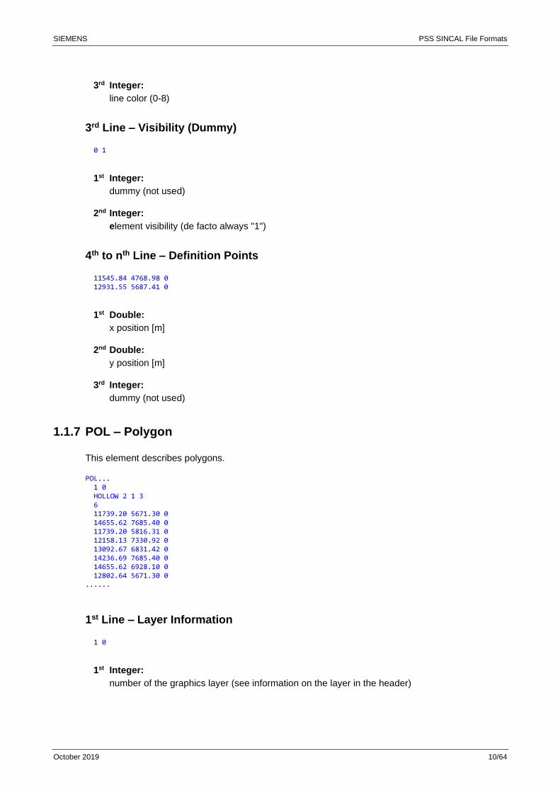
1.1.7 POL – Polygon
This element describes polygons.
POL... 1 0 HOLLOW 2 1 3 6 11739.20 5671.30 0 14655.62 7685.40 0 11739.20 5816.31 0 12158.13 7330.92 0 13092.67 6831.42 0 14236.69 7685.40 0 14655.62 6928.10 0 12802.64 5671.30 0 ......
1st Line – Layer Information
1 0
1st Integer:
number of the graphics layer (see information on the layer in the header)
SIEMENS PSS SINCAL File Formats
October 2019 11/64
2nd Integer:
dummy (not used)
3rd Char:
short name for variant (only if the graphic element has been included in a variant)
2nd Line – Screen Attributes
HOLLOW 2 1 3
1st Char:
fill pattern ("HOLLOW", "VERTICAL", "HORIZONTAL", "PLUS45", "MINUS45", "CROSSED",
"CROSSED45" and "FILLED")
2nd Double:
line width [m]
3rd Integer:
line color
4th Integer:
background color
3rd Line – Number of Points
6
1st Integer:
number of polygon points (can be ignored, since PSS SINCAL always reads up to the end
signature!)
4th Line and 5th Line – Cover, 6th to nth Line – Definition Points
11739.20 5671.30 0 14655.62 7685.40 0 11739.20 5816.31 0 12158.13 7330.92 0 13092.67 6831.42 0
1st Double:
x position [m]
2nd Double:
y position [m]
3rd Integer:
dummy (not used)
Caution: The 4th and 5th lines include the bounding box of the polygon. The actual polygon points do
not appear before the 6th line!
SIEMENS PSS SINCAL File Formats
October 2019 12/64
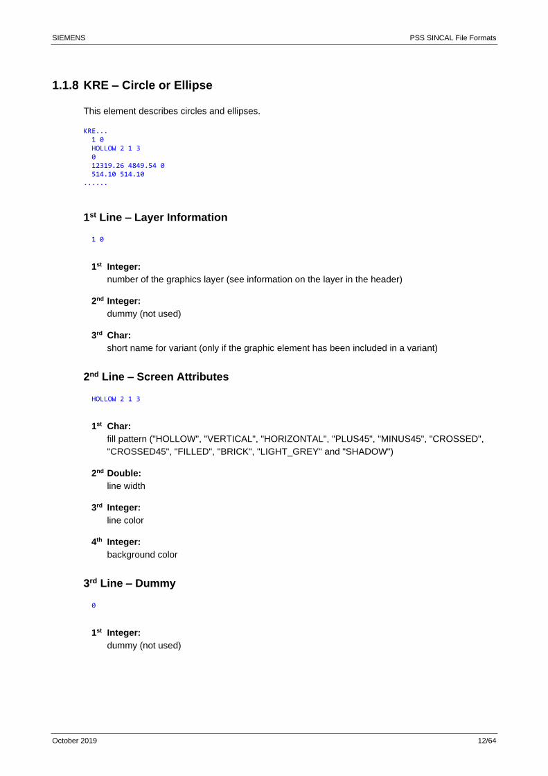
1.1.8 KRE – Circle or Ellipse
This element describes circles and ellipses.
KRE... 1 0 HOLLOW 2 1 3 0 12319.26 4849.54 0 514.10 514.10 ......
1st Line – Layer Information
1 0
1st Integer:
number of the graphics layer (see information on the layer in the header)
2nd Integer:
dummy (not used)
3rd Char:
short name for variant (only if the graphic element has been included in a variant)
2nd Line – Screen Attributes
HOLLOW 2 1 3
1st Char:
fill pattern ("HOLLOW", "VERTICAL", "HORIZONTAL", "PLUS45", "MINUS45", "CROSSED",
"CROSSED45", "FILLED", "BRICK", "LIGHT_GREY" and "SHADOW")
2nd Double:
line width
3rd Integer:
line color
4th Integer:
background color
3rd Line – Dummy
0
1st Integer:
dummy (not used)
SIEMENS PSS SINCAL File Formats
October 2019 13/64
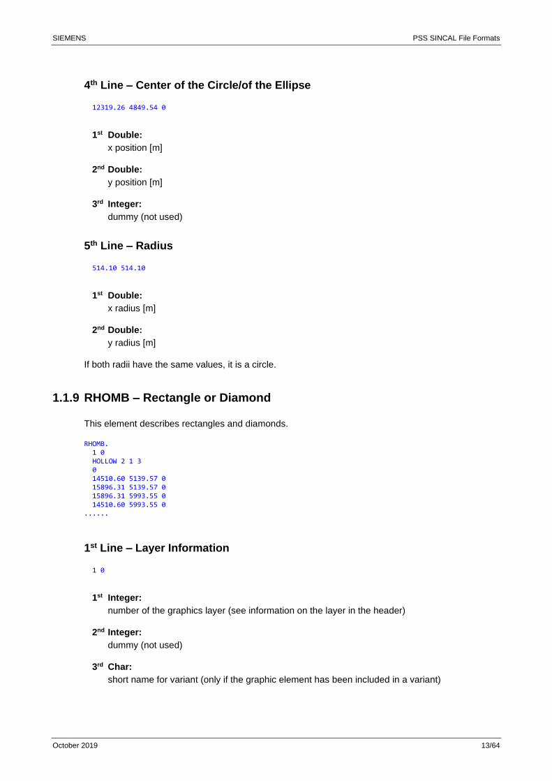
4th Line – Center of the Circle/of the Ellipse
12319.26 4849.54 0
1st Double:
x position [m]
2nd Double:
y position [m]
3rd Integer:
dummy (not used)
5th Line – Radius
514.10 514.10
1st Double:
x radius [m]
2nd Double:
y radius [m]
If both radii have the same values, it is a circle.
1.1.9 RHOMB – Rectangle or Diamond
This element describes rectangles and diamonds.
RHOMB. 1 0 HOLLOW 2 1 3 0 14510.60 5139.57 0 15896.31 5139.57 0 15896.31 5993.55 0 14510.60 5993.55 0 ......
1st Line – Layer Information
1 0
1st Integer:
number of the graphics layer (see information on the layer in the header)
2nd Integer:
dummy (not used)
3rd Char:
short name for variant (only if the graphic element has been included in a variant)
SIEMENS PSS SINCAL File Formats
October 2019 14/64
2nd Line – Screen Attributes
HOLLOW 2 1 3
1st Char:
fill pattern ("HOLLOW", "VERTICAL", "HORIZONTAL", "PLUS45", "MINUS45", "CROSSED",
"CROSSED45", "FILLED", "BRICK", "LIGHT_GREY" and "SHADOW")
2nd Double:
line width
3rd Integer:
line color
4th Integer:
background color
3rd Line – Dummy
0
1st Integer:
dummy (not used)
4th to 7th Line – Definition Points
14510.60 5139.57 0 15896.31 5139.57 0 15896.31 5993.55 0 14510.60 5993.55 0
1st Double:
x position [m]
2nd Double:
y position [m]
3rd Integer:
dummy (not used)
1.1.10 PIE – Arc of a Circle or Circle Segment
This element describes arcs and segments of circles.
PIE... 1 0 HOLLOW 2 1 3 0 3120.810 1594.348 0 3.000 3.000 270 180 ......
SIEMENS PSS SINCAL File Formats
October 2019 15/64
1st Line – Layer Information
1 0
1st Integer:
number of the graphics layer (see information on the layer in the header)
2nd Integer:
dummy (not used)
3rd Char:
short name for variant (only if the graphic element has been included in a variant)
2nd Line – Screen Attributes
HOLLOW 2 1 3
1st Char:
fill pattern ("HOLLOW", "VERTICAL", "HORIZONTAL", "PLUS45", "MINUS45", "CROSSED",
"CROSSED45", "FILLED", "BRICK", "LIGHT_GREY" and "SHADOW")
2nd Double:
line width
3rd Integer:
line color
4th Integer:
background color
3rd Line – Object Selection
0
1st Integer:
0 = arc of a circle or 1 = circle segment
4th Line – Center of the Circle/Ellipse
3120.810 1594.348 0
1st Double:
x position [m]
2nd Double:
y position [m]
3rd Integer:
dummy (not used)
SIEMENS PSS SINCAL File Formats
October 2019 16/64
5th Line – Radius
3.000 3.000
1st Double:
x radius [m]
2nd Double:
y radius [m]
If both radii have the same values, it is a circle.
6th Line – Angle
270 180
1st Double:
angle at start [°]
2nd Double:
angle at end [°]
1.1.11 GRP_START/GRP_END – Groups
This element defines a group for those elements.
GRP_START ...... n-elements… GRP_END.. ......
These elements contain no other information.
GRP_START is the beginning of a group. GRP_END is the end of the group. All elements (e.g.
PLIN.., VTXT.., KRE..., etc.) between GRP_START and GRP_END are grouped.
Comments
Groups are only available if the PIC file has been imported to PSS SINCAL 16.0 as a graphic
element.
1.2 Help Program VecToPic
The help program VecToPic converts vector graphics into PIC files. These PIC files can be used both
to display the background picture and to import graphic objects into PSS SINCAL.
The PIC file contains vector graphics in a specific PSS SINCAL format. Compared to other vector
graphic formats, these have the advantage of being able to be processed very efficiently and even
SIEMENS PSS SINCAL File Formats
October 2019 17/64
have possibilities for editing them in PSS SINCAL.
The program VecToPic can be started by:
• Graphic User Interface
• Command Prompt
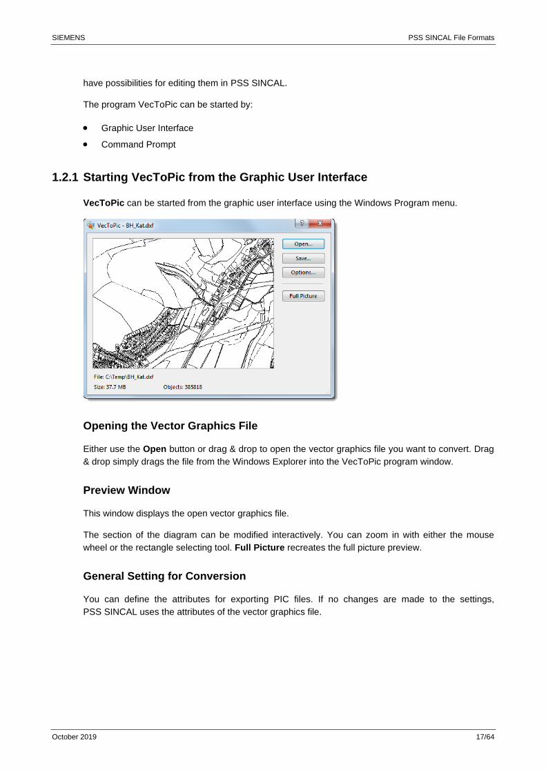
1.2.1 Starting VecToPic from the Graphic User Interface
VecToPic can be started from the graphic user interface using the Windows Program menu.
Opening the Vector Graphics File
Either use the Open button or drag & drop to open the vector graphics file you want to convert. Drag
& drop simply drags the file from the Windows Explorer into the VecToPic program window.
Preview Window
This window displays the open vector graphics file.
The section of the diagram can be modified interactively. You can zoom in with either the mouse
wheel or the rectangle selecting tool. Full Picture recreates the full picture preview.
General Setting for Conversion
You can define the attributes for exporting PIC files. If no changes are made to the settings,
PSS SINCAL uses the attributes of the vector graphics file.
SIEMENS PSS SINCAL File Formats
October 2019 18/64
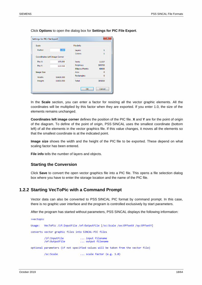
Click Options to open the dialog box for Settings for PIC File Export.
In the Scale section, you can enter a factor for resizing all the vector graphic elements. All the
coordinates will be multiplied by this factor when they are exported. If you enter 1.0, the size of the
elements remains unchanged.
Coordinates left image corner defines the position of the PIC file. X and Y are for the point of origin
of the diagram. To define of the point of origin, PSS SINCAL uses the smallest coordinate (bottom
left) of all the elements in the vector graphics file. If this value changes, it moves all the elements so
that the smallest coordinate is at the indicated point.
Image size shows the width and the height of the PIC file to be exported. These depend on what
scaling factor has been entered.
File info tells the number of layers and objects.
Starting the Conversion
Click Save to convert the open vector graphics file into a PIC file. This opens a file selection dialog
box where you have to enter the storage location and the name of the PIC file.
1.2.2 Starting VecToPic with a Command Prompt
Vector data can also be converted to PSS SINCAL PIC format by command prompt. In this case,
there is no graphic user interface and the program is controlled exclusively by start parameters.
After the program has started without parameters, PSS SINCAL displays the following information:
>vectopic Usage: VecToPic /if:InputFile /of:OutputFile [/sc:Scale /ox:OffsetX /oy:OffsetY] converts vector graphic files into SINCAL-PIC files /if:InputFile ... input filename /of:OutputFile ... output filename optional parameters (if not specified values will be taken from the vector file) /sc:Scale ... scale factor (e.g. 1.0)
SIEMENS PSS SINCAL File Formats
October 2019 19/64
/ox:OffsetX ... offset x to add (e.g. 0.0) /oy:OffsetY ... offset y to add (e.g. 0.0)
The parameters for "if" and "of" are required. These parameters define input and output files.
All other parameters are optional. They control the conversion procedure.
The scale of data is controlled with the general parameter "sc", which allows graphic data to be
enlarged or reduced. This factor converts the data from the input file into the PSS SINCAL coordinate
system based on [m].
The general parameters "ox" and "oy" let you move the converted data within the PSS SINCAL
coordinate system. The values for the movement are input in [m].
Example of the Conversion of a DXF File
NT>vectopic /if:corpa.dxf /of:corpa.pic /sc:1000 Status ====== input file: corpa.dxf output file: corpa.pic objects : 4330 scale : 1:1000 offset(x/y): 0.000000 0.000000
In the above example, the DXF file "corpa.dxf" is changed into the PSS SINCAL PIC file "corpa.pic".
The scale factor is 1:1000, which means that a DXF unit is converted to 1000 mm in the
PSS SINCAL PIC file.
1.2.3 Integrating PIC Files into PSS SINCAL
PSS SINCAL can display PIC files in two different ways:
• As background pictures
• As imported graphic objects
Background Pictures
PSS SINCAL displays background pictures to scale beneath the actual networks. You can, for
example, use maps or cadastral maps for PSS SINCAL networks. Simply draw on top of these to
create a network to scale. The background pictures are only used for visualization, the objects
cannot be edited. This lets you display that background pictures with several thousand objects
extremely quickly.
The Importing Graphics function integrates background pictures.
Importing Graphic Objects
This function imports vector graphics in PSS SINCAL PIC format into PSS SINCAL networks. Unlike
the Importing Graphics function, these graphic objects can be modified once they are imported.
The Importing Graphic Objects function imports the objects.
SIEMENS PSS SINCAL File Formats
October 2019 20/64
2 PSS SINCAL Symbol Files
PSS SINCAL lets you create user-defined symbols for network elements in electrical and pipe
networks. These symbols are defined with simple XML files.
2.1 General Remarks
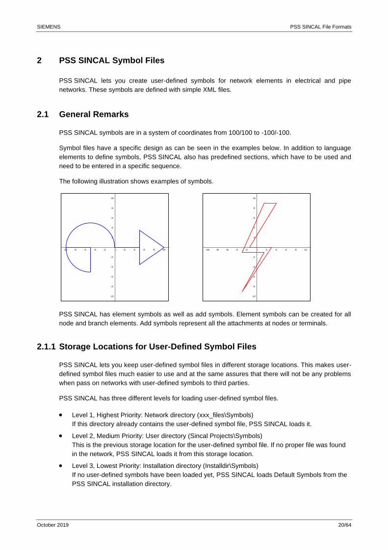
PSS SINCAL symbols are in a system of coordinates from 100/100 to -100/-100.
Symbol files have a specific design as can be seen in the examples below. In addition to language
elements to define symbols, PSS SINCAL also has predefined sections, which have to be used and
need to be entered in a specific sequence.
The following illustration shows examples of symbols.
PSS SINCAL has element symbols as well as add symbols. Element symbols can be created for all
node and branch elements. Add symbols represent all the attachments at nodes or terminals.
2.1.1 Storage Locations for User-Defined Symbol Files
PSS SINCAL lets you keep user-defined symbol files in different storage locations. This makes user-
defined symbol files much easier to use and at the same assures that there will not be any problems
when pass on networks with user-defined symbols to third parties.
PSS SINCAL has three different levels for loading user-defined symbol files.
• Level 1, Highest Priority: Network directory (xxx_files\Symbols)
If this directory already contains the user-defined symbol file, PSS SINCAL loads it.
• Level 2, Medium Priority: User directory (Sincal Projects\Symbols)
This is the previous storage location for the user-defined symbol file. If no proper file was found
in the network, PSS SINCAL loads it from this storage location.
• Level 3, Lowest Priority: Installation directory (Installdir\Symbols)
If no user-defined symbols have been loaded yet, PSS SINCAL loads Default Symbols from the
PSS SINCAL installation directory.
-100 1008040 6020-80 -40-60 -20
100
80
40
60
20
-100
-80
-40
-60
-20
0 -100 1008040 6020-80 -40-60 -20
100
80
40
60
20
-100
-80
-40
-60
-20
0

SIEMENS PSS SINCAL File Formats
October 2019 21/64
2.2 Example for the Symbol File
<?xml version="1.0" encoding="UTF-8"?> <!-- Electro Symbols (User-Defined) for PSS SINCAL --> <Shapes> <Library> <!-- Single Port Elements --> <UserSinglePort> <Symbol Name="User-Symbol" Code="999"> <Terminal No="1" TerminalX="0" TerminalY="-100"> Drawing Command </Terminal> </Symbol> </UserSinglePort> <!-- Two Port Elements --> <UserTwoPort> <Symbol Name="User-Symbol" Code="999"> <Terminal No="1" TerminalX="0" TerminalY="-100"> Drawing Command </Terminal> <Terminal No="2" TerminalX="0" TerminalY="100"> Drawing Command </Terminal> </Symbol> </UserTwoPort> <!-- Three Port Elements --> <UserThreePort> <Symbol Name="User-Symbol" Code="999"> <Terminal No="1" TerminalX="0" TerminalY="-95"> Drawing Command </Terminal> <Terminal No="2" TerminalX="0" TerminalY="95"> Drawing Command </Terminal> <Terminal No="3" TerminalX="120" TerminalY="0" ConnectX="60" ConnectY="0"> Drawing Command </Terminal> </Symbol> </UserThreePort> </Library> <!-- Add Symbols (Element/Node)--> <AddSymbols> <Symbol ID="1" Name="User Fault" X1="-90" Y1="0" X2="90" Y2="0"> <Common> Drawing Command </Common> <Open> Drawing Command </Open> <Close> Drawing Command </Close> </Symbol> </AddSymbols> <!-- Add Symbols (Breaker) --> <AddSymbolBreaker> <Symbol ID="999" Name="User Breaker" X1="-10" Y1="0" X2="10" Y2="0"> <Common> Drawing Command </Common> <Open> Drawing Command </Open> <Close> Drawing Command </Close> </Symbol> </AddSymbolBreaker> </Shapes>
SIEMENS PSS SINCAL File Formats
October 2019 22/64
2.3 Symbols for Network Elements
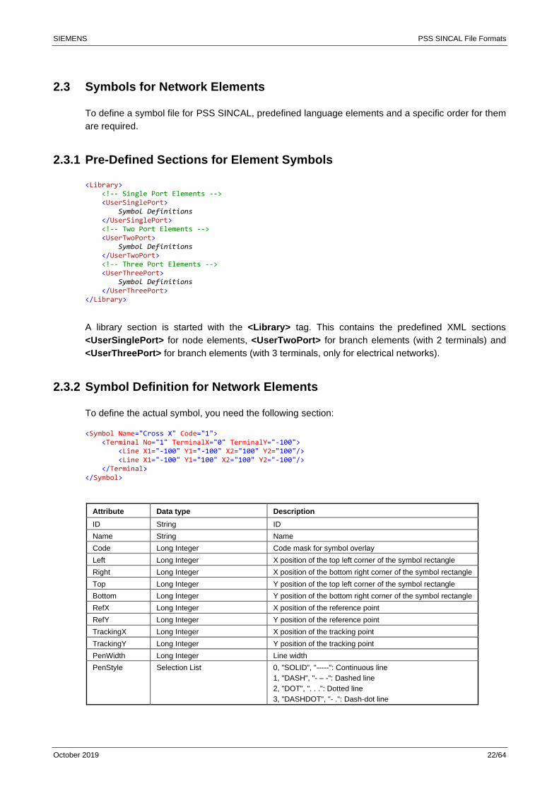
To define a symbol file for PSS SINCAL, predefined language elements and a specific order for them
are required.
2.3.1 Pre-Defined Sections for Element Symbols
<Library> <!-- Single Port Elements --> <UserSinglePort> Symbol Definitions </UserSinglePort> <!-- Two Port Elements --> <UserTwoPort> Symbol Definitions </UserTwoPort> <!-- Three Port Elements --> <UserThreePort> Symbol Definitions </UserThreePort> </Library>
A library section is started with the <Library> tag. This contains the predefined XML sections
<UserSinglePort> for node elements, <UserTwoPort> for branch elements (with 2 terminals) and
<UserThreePort> for branch elements (with 3 terminals, only for electrical networks).
2.3.2 Symbol Definition for Network Elements
To define the actual symbol, you need the following section:
<Symbol Name="Cross X" Code="1"> <Terminal No="1" TerminalX="0" TerminalY="-100"> <Line X1="-100" Y1="-100" X2="100" Y2="100"/> <Line X1="-100" Y1="100" X2="100" Y2="-100"/> </Terminal> </Symbol>
Attribute Data type Description
ID String ID
Name String Name
Code Long Integer Code mask for symbol overlay
Left Long Integer X position of the top left corner of the symbol rectangle
Right Long Integer X position of the bottom right corner of the symbol rectangle
Top Long Integer Y position of the top left corner of the symbol rectangle
Bottom Long Integer Y position of the bottom right corner of the symbol rectangle
RefX Long Integer X position of the reference point
RefY Long Integer Y position of the reference point
TrackingX Long Integer X position of the tracking point
TrackingY Long Integer Y position of the tracking point
PenWidth Long Integer Line width
PenStyle Selection List 0, "SOLID", "-----": Continuous line
1, "DASH", "- – -": Dashed line
2, "DOT", ". . .": Dotted line
3, "DASHDOT", "- .": Dash-dot line
SIEMENS PSS SINCAL File Formats
October 2019 23/64
4, "DASHDOTDOT", "- . .": Dash-dot-dot line
FillColor Selection List (separated by ",") "FORE": Foreground color
"BACK": Background color
"BASE": Basic color
"NOPEN": No line
"NOBACK": Transparent
NoPen Boolean No line
HitTest Boolean Check mouse hits
Rotate Boolean Rotate symbol
The section consists of an ID and the required attributes. Within this section, the number of the
terminal sections is defined which contain the individual drawing instructions.
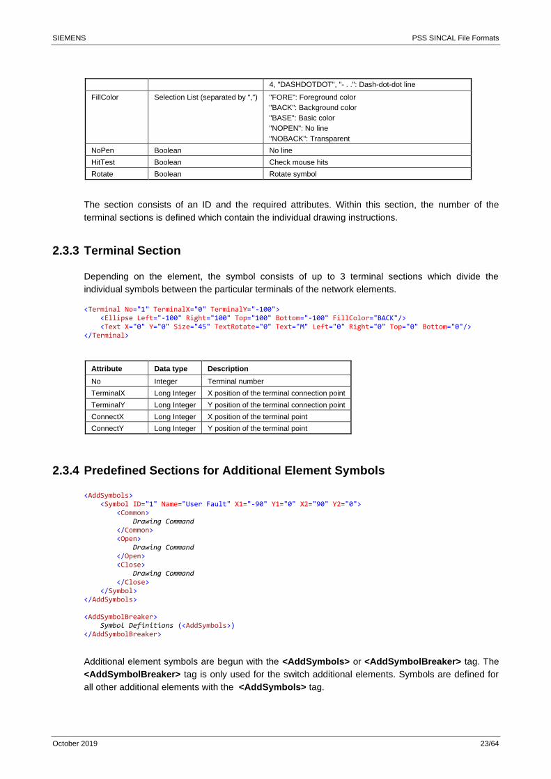
2.3.3 Terminal Section
Depending on the element, the symbol consists of up to 3 terminal sections which divide the
individual symbols between the particular terminals of the network elements.
<Terminal No="1" TerminalX="0" TerminalY="-100"> <Ellipse Left="-100" Right="100" Top="100" Bottom="-100" FillColor="BACK"/> <Text X="0" Y="0" Size="45" TextRotate="0" Text="M" Left="0" Right="0" Top="0" Bottom="0"/> </Terminal>
Attribute Data type Description
No Integer Terminal number
TerminalX Long Integer X position of the terminal connection point
TerminalY Long Integer Y position of the terminal connection point
ConnectX Long Integer X position of the terminal point
ConnectY Long Integer Y position of the terminal point
2.3.4 Predefined Sections for Additional Element Symbols
<AddSymbols> <Symbol ID="1" Name="User Fault" X1="-90" Y1="0" X2="90" Y2="0"> <Common> Drawing Command </Common> <Open> Drawing Command </Open> <Close> Drawing Command </Close> </Symbol> </AddSymbols> <AddSymbolBreaker> Symbol Definitions (<AddSymbols>) </AddSymbolBreaker>
Additional element symbols are begun with the <AddSymbols> or <AddSymbolBreaker> tag. The
<AddSymbolBreaker> tag is only used for the switch additional elements. Symbols are defined for
all other additional elements with the <AddSymbols> tag.
SIEMENS PSS SINCAL File Formats
October 2019 24/64
These sections contain symbol definitions with the predefined section <Common>, which defines the
general symbol. Besides this symbol it is possible to extend this according to the switching state of
the additional element. This is done via the sections <Open> and <Close>.
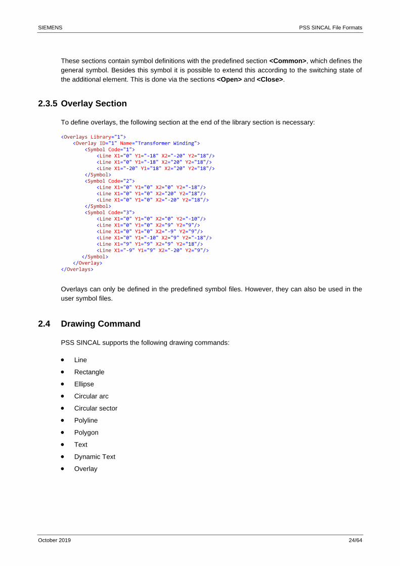
2.3.5 Overlay Section
To define overlays, the following section at the end of the library section is necessary:
<Overlays Library="1"> <Overlay ID="1" Name="Transformer Winding"> <Symbol Code="1"> <Line X1="0" Y1="-18" X2="-20" Y2="18"/> <Line X1="0" Y1="-18" X2="20" Y2="18"/> <Line X1="-20" Y1="18" X2="20" Y2="18"/> </Symbol> <Symbol Code="2"> <Line X1="0" Y1="0" X2="0" Y2="-18"/> <Line X1="0" Y1="0" X2="20" Y2="18"/> <Line X1="0" Y1="0" X2="-20" Y2="18"/> </Symbol> <Symbol Code="3"> <Line X1="0" Y1="0" X2="0" Y2="-10"/> <Line X1="0" Y1="0" X2="9" Y2="9"/> <Line X1="0" Y1="0" X2="-9" Y2="9"/> <Line X1="0" Y1="-10" X2="9" Y2="-18"/> <Line X1="9" Y1="9" X2="9" Y2="18"/> <Line X1="-9" Y1="9" X2="-20" Y2="9"/> </Symbol> </Overlay> </Overlays>
Overlays can only be defined in the predefined symbol files. However, they can also be used in the
user symbol files.
2.4 Drawing Command
PSS SINCAL supports the following drawing commands:
• Line
• Rectangle
• Ellipse
• Circular arc
• Circular sector
• Polyline
• Polygon
• Text
• Dynamic Text
• Overlay
SIEMENS PSS SINCAL File Formats
October 2019 25/64
2.4.1 Base Attributes
Attribute Data type Description
PenWidth Long Integer Line width
PenStyle Selection List 0, "SOLID", "-----": Continuous line
1, "DASH", "- – -": Dashed line
2, "DOT", ". . .": Dotted line
3, "DASHDOT", "- .": Dash-dot line
4, "DASHDOTDOT", "- . .": Dash-dot-dot line
FillColor Selection List (separated by ",") "FORE": Foreground color
"BACK": Background color
"BASE": Basic color
"NOPEN": No line
"NOBACK": Transparent
NoPen Boolean No line
HitTest Boolean Check mouse hits
Rotate Boolean Rotate symbol
2.4.2 Fill Pattern
The following values are permitted for the fill pattern argument:
Value 0 1 2 3 4 5 6
Pattern
2.4.3 Line
Attribute Data type Description
X1 Long Integer X position of the start point
X2 Long Integer X position of the end point
Y1 Long Integer Y position of the start point
Y2 Long Integer Y position of the end point
Lines are defined from X1/Y1 (starting point of the line) to X2/Y2 (end point of the line).
2.4.4 Rectangle
Attribute Data type Description
Left Long Integer X position of the top left corner
Right Long Integer X position of the bottom right corner
Top Long Integer Y position of the top left corner
Bottom Long Integer Y position of the bottom right corner
Visible Boolean Visible/invisible
Hatch Long Integer 1: Upward hatch ////
2: Horizontal and vertical crosshatch ++++
3: Crosshatch xxxx
SIEMENS PSS SINCAL File Formats
October 2019 26/64
4: Downward hatch \\\\
5: Horizontal hatch -----
6: Vertical hatch |||||
<Rect Left="-5" Right="5" Top="50" Bottom="-20" Hatch="3" FillColor="BACK" Visible="No"/>
A rectangle is defined with the specified fill pattern from the top left corner of the rectangle to the
bottom right corner of the rectangle.
2.4.5 Ellipse
Attribute Data type Description
Left Long Integer X position of the top left corner
Right Long Integer X position of the bottom right corner
Top Long Integer Y position of the top left corner
Bottom Long Integer Y position of the bottom right corner
Visible Boolean Visible/invisible
Hatch Long Integer 1: Upward hatch ////
2: Horizontal and vertical crosshatch ++++
3: Crosshatch xxxx
4: Downward hatch \\\\
5: Horizontal hatch -----
6: Vertical hatch |||||
<Ellipse Left="-100" Right="100" Top="100" Bottom="-100" FillColor="BACK"/>
Ellipses are defined in a rectangle and given a fill pattern.
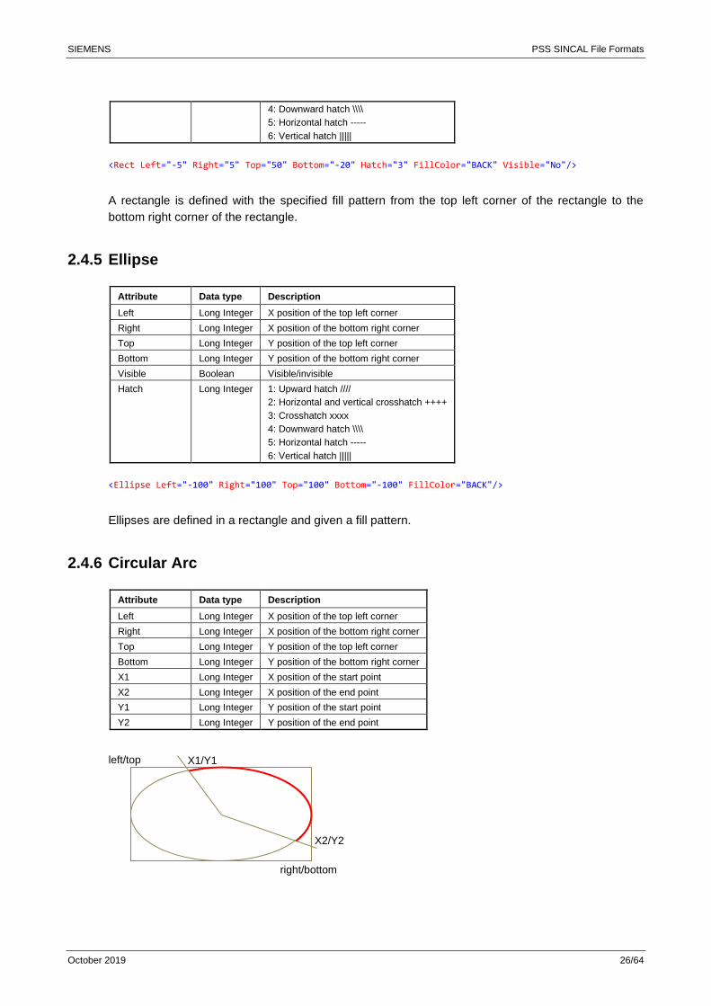
2.4.6 Circular Arc
Attribute Data type Description
Left Long Integer X position of the top left corner
Right Long Integer X position of the bottom right corner
Top Long Integer Y position of the top left corner
Bottom Long Integer Y position of the bottom right corner
X1 Long Integer X position of the start point
X2 Long Integer X position of the end point
Y1 Long Integer Y position of the start point
Y2 Long Integer Y position of the end point
X2/Y2
X1/Y1 left/top
right/bottom

SIEMENS PSS SINCAL File Formats
October 2019 27/64
In the indicated rectangle (left/top – right/bottom), circular arcs are defined from the starting point
X1/Y1 to the end point X2/Y2.
Start and end points do not have to be located directly on the circular arc.
Circular arcs are created clockwise (from the starting point to the end point).
2.4.7 Circular Sector
Attribute Data type Description
Left Long Integer X position of the top left corner
Right Long Integer X position of the bottom right corner
Top Long Integer Y position of the top left corner
Bottom Long Integer Y position of the bottom right corner
X1 Long Integer X position of the start point
X2 Long Integer X position of the end point
Y1 Long Integer Y position of the start point
Y2 Long Integer Y position of the end point
Visible Boolean Visible/invisible
Hatch Long Integer 1: Upward hatch ////
2: Horizontal and vertical crosshatch ++++
3: Crosshatch xxxx
4: Downward hatch \\\\
5: Horizontal hatch -----
6: Vertical hatch |||||
<Pie Left="-30" Right="30" Top="-80" Bottom="-30" FillColor="FORE" Rotate="0" X1="30" Y1="-55" X2="-30" Y2="-55"/>
In the indicated rectangle (left/top – right/bottom), circular sectors are defined from the starting point
X1/Y1 to the end point X2/Y2.
Start and end points do not have to be located directly on the circular arc.
Circular sectors are created clockwise (from the starting point to the end point).
2.4.8 Polyline
<Polyline> 30,90|-15,10|30,10|-15,-90|-40,-90|15,0|-30,0|30,90| </Polyline>
A polyline defines a line with multiple line segments and is defined by specifying XY pairs
(X1,Y1|X2,Y2|…Xn,Yn|).
X2/Y2
X1/Y1 left/top
right/bottom
SIEMENS PSS SINCAL File Formats
October 2019 28/64
2.4.9 Polygon
<Polygon FillColor="BACK">-35,50|35,50|0,100|</Polygon>
A polygon is defined filled with the indicated coordinates (X/Y pairs) and with the indicated fill pattern.
2.4.10 Text
Attribute Data type Description
X Long Integer X position
Y Long Integer Y position
Size Long Integer Text size
Font String Font name
Text String Displayed text
TextRotate Boolean Rotation of the text with the symbol
Style Selection List (separated by ",") ITALIC
BOLD
UNDERLINE
STRIKEOUT
<Text X="-15" Y="-75" Size="15" TextRotate="0" Text="MF"/>
Text is defined at the indicated position X/Y and the size.
2.4.11 Dynamic Text
Attribute Data type Description
X Long Integer X position
Y Long Integer Y position
Size Long Integer Text size
Font String Font name
Text String Displayed text
DynText String Displayed text with &[ token support
TextRotate Boolean Rotation of the text with the symbol
Style Selection List (separated by ",") ITALIC
BOLD
UNDERLINE
STRIKEOUT
Text is defined at the indicated position X/Y and the size. The text is aligned and rotated on the basis
of the angle of the entire symbol.
2.4.12 Overlay
Attribute Data type Description
Type String Overlay type
Terminal Integer Terminal number
Overlay Long Integer Overlay ID
SIEMENS PSS SINCAL File Formats
October 2019 29/64
X Long Integer X position of the overlay
Y Long Integer Y position of the overlay
OverlayRotate Boolean Rotation activated/deactivated
<Overlay Terminal="1" Overlay="1" X="-10" Y="-55" Rotate="0"/>
An overlay defines an overlaid symbol for the indicated terminal. This symbol is provided from the
overlay section.
SIEMENS PSS SINCAL File Formats
October 2019 30/64
3 PSS SINCAL Diagrams as an XML File
PSS SINCAL diagrams can be exported to an XML file. This XML file contains all the data for the
diagram and can be edited and evaluated by any external program.
3.1 Structure of the XML File
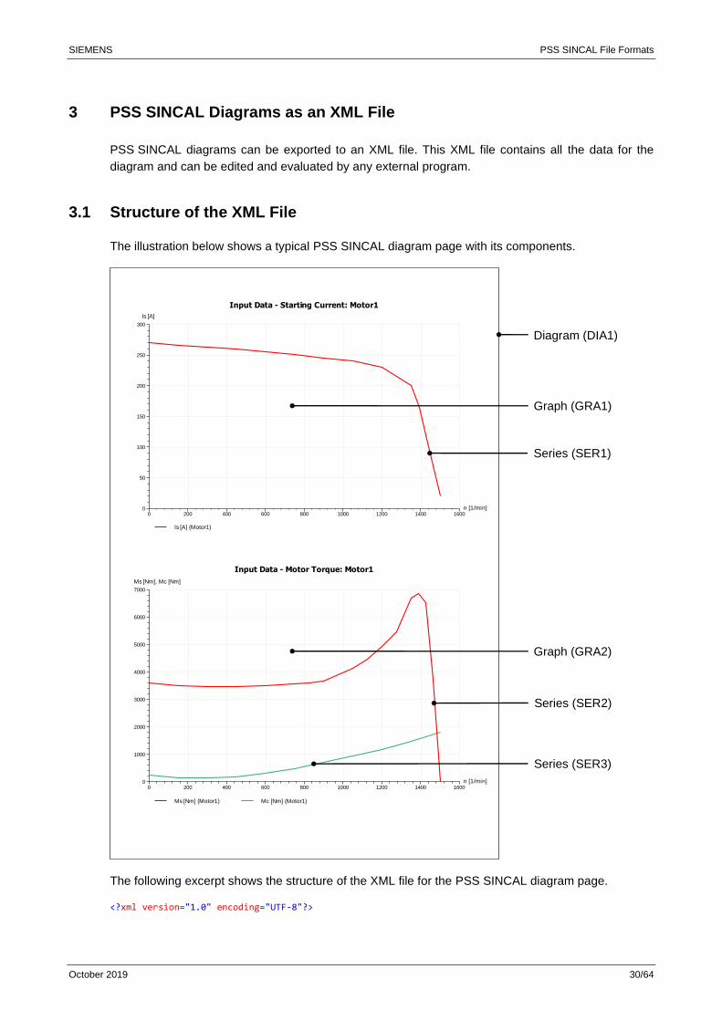
The illustration below shows a typical PSS SINCAL diagram page with its components.
The following excerpt shows the structure of the XML file for the PSS SINCAL diagram page.
<?xml version="1.0" encoding="UTF-8"?>
0 200 400 600 800 1000 1200 1400 1600n [1/min]0
50
100
150
200
250
300
Is [A]
Input Data - Starting Current: Motor1
Is [A] (Motor1)
0 200 400 600 800 1000 1200 1400 1600n [1/min]0
1000
2000
3000
4000
5000
6000
7000
Ms [Nm], Mc [Nm]
Input Data - Motor Torque: Motor1
Ms [Nm] (Motor1) Mc [Nm] (Motor1)
Diagram (DIA1)
Graph (GRA1)
Graph (GRA2)
Series (SER1)
Series (SER2)
Series (SER3)
SIEMENS PSS SINCAL File Formats
October 2019 31/64
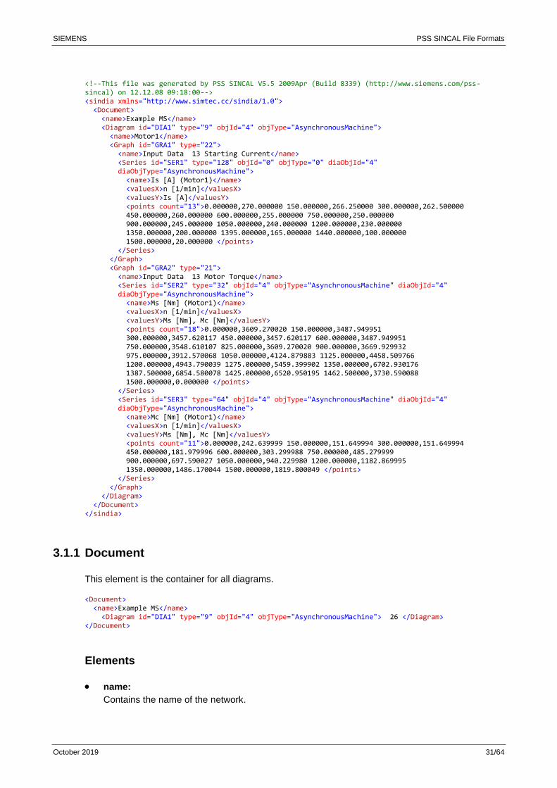
<!--This file was generated by PSS SINCAL V5.5 2009Apr (Build 8339) (http://www.siemens.com/pss-sincal) on 12.12.08 09:18:00--> <sindia xmlns="http://www.simtec.cc/sindia/1.0"> <Document> <name>Example MS</name> <Diagram id="DIA1" type="9" objId="4" objType="AsynchronousMachine"> <name>Motor1</name> <Graph id="GRA1" type="22"> <name>Input Data 13 Starting Current</name> <Series id="SER1" type="128" objId="0" objType="0" diaObjId="4" diaObjType="AsynchronousMachine"> <name>Is [A] (Motor1)</name> <valuesX>n [1/min]</valuesX> <valuesY>Is [A]</valuesY> <points count="13">0.000000,270.000000 150.000000,266.250000 300.000000,262.500000 450.000000,260.000000 600.000000,255.000000 750.000000,250.000000 900.000000,245.000000 1050.000000,240.000000 1200.000000,230.000000 1350.000000,200.000000 1395.000000,165.000000 1440.000000,100.000000 1500.000000,20.000000 </points> </Series> </Graph> <Graph id="GRA2" type="21"> <name>Input Data 13 Motor Torque</name> <Series id="SER2" type="32" objId="4" objType="AsynchronousMachine" diaObjId="4" diaObjType="AsynchronousMachine"> <name>Ms [Nm] (Motor1)</name> <valuesX>n [1/min]</valuesX> <valuesY>Ms [Nm], Mc [Nm]</valuesY> <points count="18">0.000000,3609.270020 150.000000,3487.949951 300.000000,3457.620117 450.000000,3457.620117 600.000000,3487.949951 750.000000,3548.610107 825.000000,3609.270020 900.000000,3669.929932 975.000000,3912.570068 1050.000000,4124.879883 1125.000000,4458.509766 1200.000000,4943.790039 1275.000000,5459.399902 1350.000000,6702.930176 1387.500000,6854.580078 1425.000000,6520.950195 1462.500000,3730.590088 1500.000000,0.000000 </points> </Series> <Series id="SER3" type="64" objId="4" objType="AsynchronousMachine" diaObjId="4" diaObjType="AsynchronousMachine"> <name>Mc [Nm] (Motor1)</name> <valuesX>n [1/min]</valuesX> <valuesY>Ms [Nm], Mc [Nm]</valuesY> <points count="11">0.000000,242.639999 150.000000,151.649994 300.000000,151.649994 450.000000,181.979996 600.000000,303.299988 750.000000,485.279999 900.000000,697.590027 1050.000000,940.229980 1200.000000,1182.869995 1350.000000,1486.170044 1500.000000,1819.800049 </points> </Series> </Graph> </Diagram> </Document> </sindia>
3.1.1 Document
This element is the container for all diagrams.
<Document> <name>Example MS</name> <Diagram id="DIA1" type="9" objId="4" objType="AsynchronousMachine"> 26 </Diagram> </Document>
Elements
• name:
Contains the name of the network.

SIEMENS PSS SINCAL File Formats
October 2019 32/64
• Diagram:
Container for an individual diagram.
A Document element can have any number of Diagram elements.
3.1.2 Diagram
This element describes a diagram compilation.
<Diagram id="DIA1" type="9" objId="4" objType="AsynchronousMachine"> <name>Motor1</name> <Graph id="GRA1" type="22"> 26 </Graph> </Diagram>
Attributes
• id:
A unique sequence of characters that uniquely identifies each Diagram in the XML file.
• type:
Type of diagram.
For example, 9 would stand for a "Motor Start-Up Diagram" (see the chapter on "Predefined
Types").
• objId:
Unique object ID of the element displayed in the diagram compilation.
This attribute does not exist for user-compiled diagrams, since the diagram compilation can
contain more than one element.
• objType:
Object type of the element displayed in the diagram compilation.
The object type is the same as the name of the table in the network database.
Elements
• name:
Name of the diagram compilation.
• Graph:
Container for a graph.
Diagram element can have any number of Graph elements.
3.1.3 Graph
This element describes a graph of the diagram. The Graph element combines different Series
elements to a diagram.
<Graph id="GRA1" type="22"> <name>Input Data 13 Starting Current</name> <Series> 26 </Series> </Graph>
SIEMENS PSS SINCAL File Formats
October 2019 33/64
Attributes
• id:
A unique sequence of characters that uniquely identifies each Graph in the XML file.
• type:
Type of Graph.
For example, 22 would stand for the "Motor Start-Up Current" Graph (see the chapter on
"Predefined Types").
Elements
• name:
Name of the Graph.
• Series:
A characteristic curve that contains the actual data values.
A Graph element can contain any number of Series elements.
3.1.4 Series
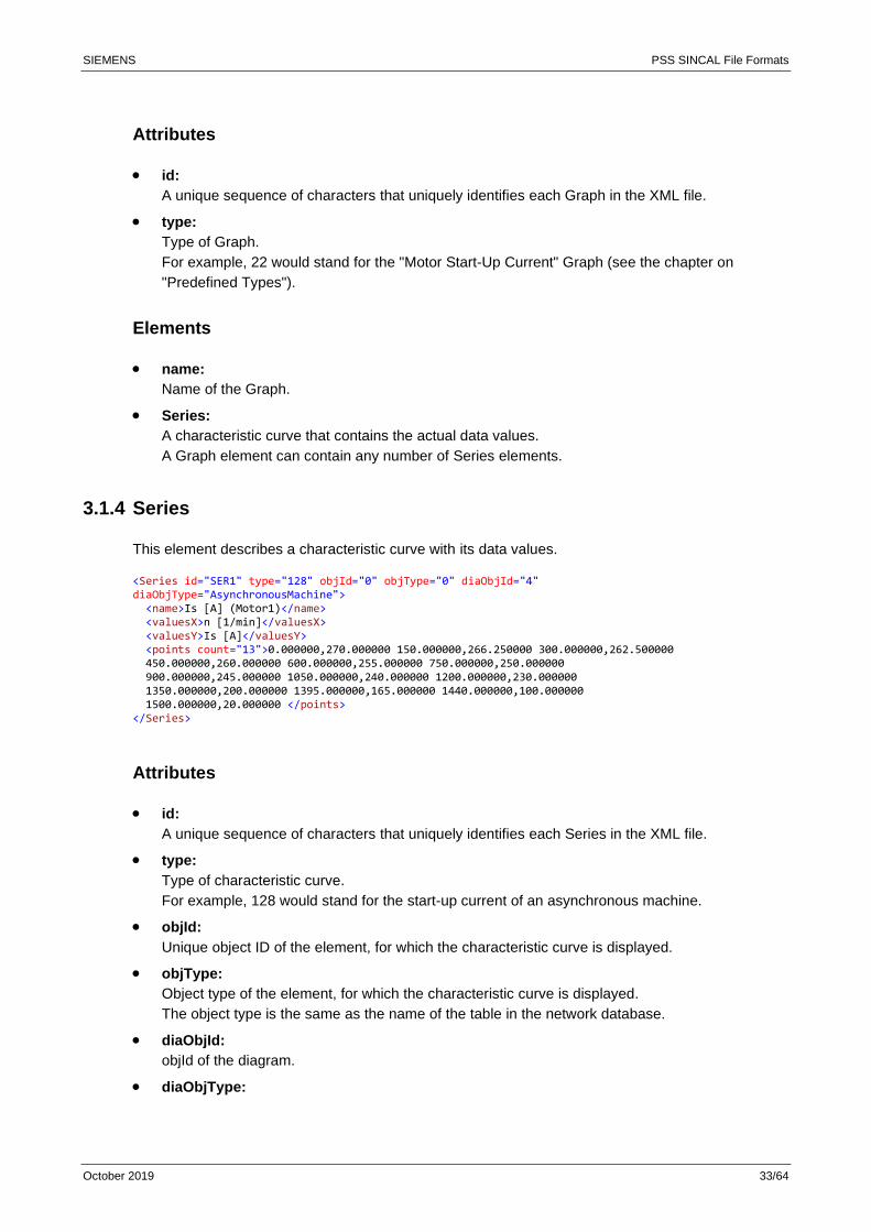
This element describes a characteristic curve with its data values.
<Series id="SER1" type="128" objId="0" objType="0" diaObjId="4" diaObjType="AsynchronousMachine"> <name>Is [A] (Motor1)</name> <valuesX>n [1/min]</valuesX> <valuesY>Is [A]</valuesY> <points count="13">0.000000,270.000000 150.000000,266.250000 300.000000,262.500000 450.000000,260.000000 600.000000,255.000000 750.000000,250.000000 900.000000,245.000000 1050.000000,240.000000 1200.000000,230.000000 1350.000000,200.000000 1395.000000,165.000000 1440.000000,100.000000 1500.000000,20.000000 </points> </Series>
Attributes
• id:
A unique sequence of characters that uniquely identifies each Series in the XML file.
• type:
Type of characteristic curve.
For example, 128 would stand for the start-up current of an asynchronous machine.
• objId:
Unique object ID of the element, for which the characteristic curve is displayed.
• objType:
Object type of the element, for which the characteristic curve is displayed.
The object type is the same as the name of the table in the network database.
• diaObjId:
objId of the diagram.
• diaObjType:
SIEMENS PSS SINCAL File Formats
October 2019 34/64
objType of the diagram.
Elements
• name:
Name of the characteristic curve.
• valuesX, valuesY:
X or Y axis of the characteristic curve with the name and unit.
• points:
points of the characteristic curve.
A point is made up of X and Y coordinates separated by a comma. Points, on the other hand,
are separated by a space. The number of points is noted in the count attribute.
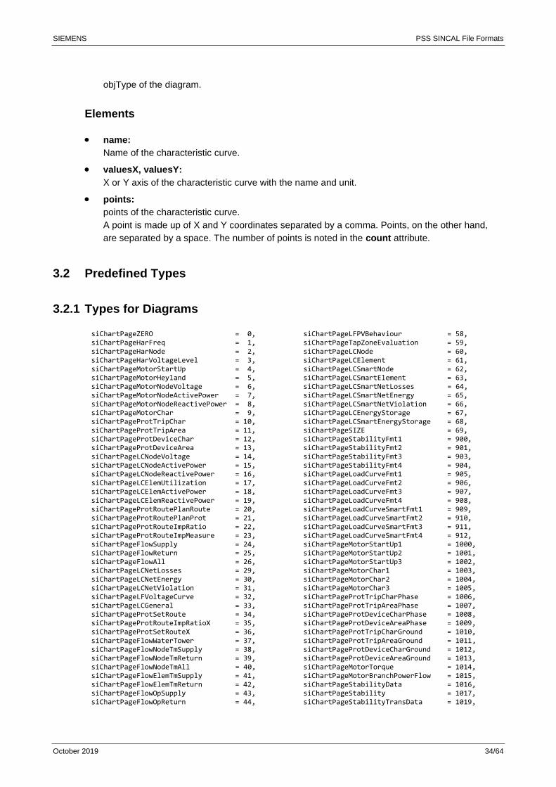
3.2 Predefined Types
3.2.1 Types for Diagrams
siChartPageZERO = 0, siChartPageHarFreq = 1, siChartPageHarNode = 2, siChartPageHarVoltageLevel = 3, siChartPageMotorStartUp = 4, siChartPageMotorHeyland = 5, siChartPageMotorNodeVoltage = 6, siChartPageMotorNodeActivePower = 7, siChartPageMotorNodeReactivePower = 8, siChartPageMotorChar = 9, siChartPageProtTripChar = 10, siChartPageProtTripArea = 11, siChartPageProtDeviceChar = 12, siChartPageProtDeviceArea = 13, siChartPageLCNodeVoltage = 14, siChartPageLCNodeActivePower = 15, siChartPageLCNodeReactivePower = 16, siChartPageLCElemUtilization = 17, siChartPageLCElemActivePower = 18, siChartPageLCElemReactivePower = 19, siChartPageProtRoutePlanRoute = 20, siChartPageProtRoutePlanProt = 21, siChartPageProtRouteImpRatio = 22, siChartPageProtRouteImpMeasure = 23, siChartPageFlowSupply = 24, siChartPageFlowReturn = 25, siChartPageFlowAll = 26, siChartPageLCNetLosses = 29, siChartPageLCNetEnergy = 30, siChartPageLCNetViolation = 31, siChartPageLFVoltageCurve = 32, siChartPageLCGeneral = 33, siChartPageProtSetRoute = 34, siChartPageProtRouteImpRatioX = 35, siChartPageProtSetRouteX = 36, siChartPageFlowWaterTower = 37, siChartPageFlowNodeTmSupply = 38, siChartPageFlowNodeTmReturn = 39, siChartPageFlowNodeTmAll = 40, siChartPageFlowElemTmSupply = 41, siChartPageFlowElemTmReturn = 42, siChartPageFlowOpSupply = 43, siChartPageFlowOpReturn = 44,
siChartPageLFPVBehaviour = 58, siChartPageTapZoneEvaluation = 59, siChartPageLCNode = 60, siChartPageLCElement = 61, siChartPageLCSmartNode = 62, siChartPageLCSmartElement = 63, siChartPageLCSmartNetLosses = 64, siChartPageLCSmartNetEnergy = 65, siChartPageLCSmartNetViolation = 66, siChartPageLCEnergyStorage = 67, siChartPageLCSmartEnergyStorage = 68, siChartPageSIZE = 69, siChartPageStabilityFmt1 = 900, siChartPageStabilityFmt2 = 901, siChartPageStabilityFmt3 = 903, siChartPageStabilityFmt4 = 904, siChartPageLoadCurveFmt1 = 905, siChartPageLoadCurveFmt2 = 906, siChartPageLoadCurveFmt3 = 907, siChartPageLoadCurveFmt4 = 908, siChartPageLoadCurveSmartFmt1 = 909, siChartPageLoadCurveSmartFmt2 = 910, siChartPageLoadCurveSmartFmt3 = 911, siChartPageLoadCurveSmartFmt4 = 912, siChartPageMotorStartUp1 = 1000, siChartPageMotorStartUp2 = 1001, siChartPageMotorStartUp3 = 1002, siChartPageMotorChar1 = 1003, siChartPageMotorChar2 = 1004, siChartPageMotorChar3 = 1005, siChartPageProtTripCharPhase = 1006, siChartPageProtTripAreaPhase = 1007, siChartPageProtDeviceCharPhase = 1008, siChartPageProtDeviceAreaPhase = 1009, siChartPageProtTripCharGround = 1010, siChartPageProtTripAreaGround = 1011, siChartPageProtDeviceCharGround = 1012, siChartPageProtDeviceAreaGround = 1013, siChartPageMotorTorque = 1014, siChartPageMotorBranchPowerFlow = 1015, siChartPageStabilityData = 1016, siChartPageStability = 1017, siChartPageStabilityTransData = 1019,
SIEMENS PSS SINCAL File Formats
October 2019 35/64
siChartPageFlowOpAll = 45, siChartPageLCOpSerAbs = 46, siChartPageLCOpSerRel = 47, siChartPageLfIncElemUtilization = 48, siChartPageLfIncSecurePower = 49, siChartPageLfIncSeriesAbs = 50, siChartPageLfIncSeriesRel = 51, siChartPageMotorNEMA = 52, siChartPageMotorNode = 53, siChartPageFlowOpBehaviourSupply = 54, siChartPageFlowOpBehaviourReturn = 55, siChartPageFlowOpBehaviourAll = 56, siChartPageSIZE = 57,
siChartPageStabilityTrans = 1020 siChartPageProtDocumentation = 1021, siChartPageInputData = 1022, siChartPageUserData = 1023, siChartPageProtDocumentation2 = 1024, siChartPageDynamicSimulationData = 1025, siChartPageDynamicSimulation = 1026, siChartPageLCResults = 1027, siChartPageLCSmartResults = 1028, siChartPageLCNetwork = 1029, siChartPageLCSmartNetwork = 1030, siChartPageEND = 1031
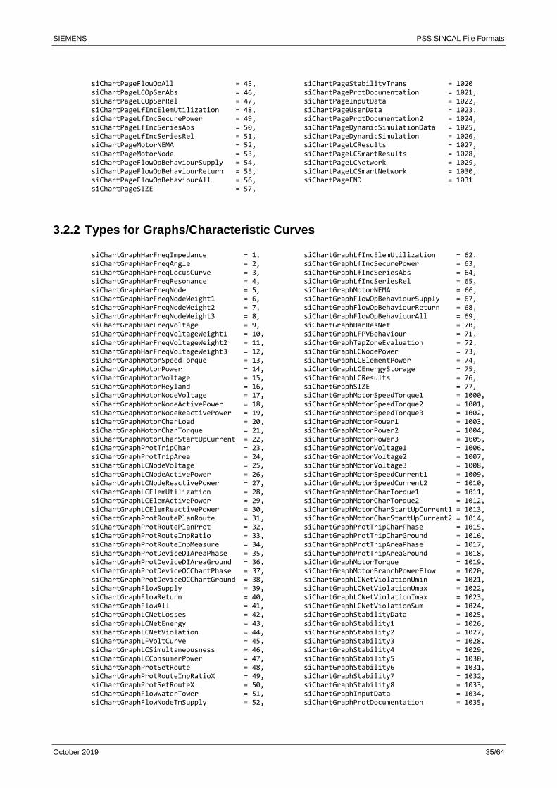
3.2.2 Types for Graphs/Characteristic Curves
siChartGraphHarFreqImpedance = 1, siChartGraphHarFreqAngle = 2, siChartGraphHarFreqLocusCurve = 3, siChartGraphHarFreqResonance = 4, siChartGraphHarFreqNode = 5, siChartGraphHarFreqNodeWeight1 = 6, siChartGraphHarFreqNodeWeight2 = 7, siChartGraphHarFreqNodeWeight3 = 8, siChartGraphHarFreqVoltage = 9, siChartGraphHarFreqVoltageWeight1 = 10, siChartGraphHarFreqVoltageWeight2 = 11, siChartGraphHarFreqVoltageWeight3 = 12, siChartGraphMotorSpeedTorque = 13, siChartGraphMotorPower = 14, siChartGraphMotorVoltage = 15, siChartGraphMotorHeyland = 16, siChartGraphMotorNodeVoltage = 17, siChartGraphMotorNodeActivePower = 18, siChartGraphMotorNodeReactivePower = 19, siChartGraphMotorCharLoad = 20, siChartGraphMotorCharTorque = 21, siChartGraphMotorCharStartUpCurrent = 22, siChartGraphProtTripChar = 23, siChartGraphProtTripArea = 24, siChartGraphLCNodeVoltage = 25, siChartGraphLCNodeActivePower = 26, siChartGraphLCNodeReactivePower = 27, siChartGraphLCElemUtilization = 28, siChartGraphLCElemActivePower = 29, siChartGraphLCElemReactivePower = 30, siChartGraphProtRoutePlanRoute = 31, siChartGraphProtRoutePlanProt = 32, siChartGraphProtRouteImpRatio = 33, siChartGraphProtRouteImpMeasure = 34, siChartGraphProtDeviceDIAreaPhase = 35, siChartGraphProtDeviceDIAreaGround = 36, siChartGraphProtDeviceOCChartPhase = 37, siChartGraphProtDeviceOCChartGround = 38, siChartGraphFlowSupply = 39, siChartGraphFlowReturn = 40, siChartGraphFlowAll = 41, siChartGraphLCNetLosses = 42, siChartGraphLCNetEnergy = 43, siChartGraphLCNetViolation = 44, siChartGraphLFVoltCurve = 45, siChartGraphLCSimultaneousness = 46, siChartGraphLCConsumerPower = 47, siChartGraphProtSetRoute = 48, siChartGraphProtRouteImpRatioX = 49, siChartGraphProtSetRouteX = 50, siChartGraphFlowWaterTower = 51, siChartGraphFlowNodeTmSupply = 52,
siChartGraphLfIncElemUtilization = 62, siChartGraphLfIncSecurePower = 63, siChartGraphLfIncSeriesAbs = 64, siChartGraphLfIncSeriesRel = 65, siChartGraphMotorNEMA = 66, siChartGraphFlowOpBehaviourSupply = 67, siChartGraphFlowOpBehaviourReturn = 68, siChartGraphFlowOpBehaviourAll = 69, siChartGraphHarResNet = 70, siChartGraphLFPVBehaviour = 71, siChartGraphTapZoneEvaluation = 72, siChartGraphLCNodePower = 73, siChartGraphLCElementPower = 74, siChartGraphLCEnergyStorage = 75, siChartGraphLCResults = 76, siChartGraphSIZE = 77, siChartGraphMotorSpeedTorque1 = 1000, siChartGraphMotorSpeedTorque2 = 1001, siChartGraphMotorSpeedTorque3 = 1002, siChartGraphMotorPower1 = 1003, siChartGraphMotorPower2 = 1004, siChartGraphMotorPower3 = 1005, siChartGraphMotorVoltage1 = 1006, siChartGraphMotorVoltage2 = 1007, siChartGraphMotorVoltage3 = 1008, siChartGraphMotorSpeedCurrent1 = 1009, siChartGraphMotorSpeedCurrent2 = 1010, siChartGraphMotorCharTorque1 = 1011, siChartGraphMotorCharTorque2 = 1012, siChartGraphMotorCharStartUpCurrent1 = 1013, siChartGraphMotorCharStartUpCurrent2 = 1014, siChartGraphProtTripCharPhase = 1015, siChartGraphProtTripCharGround = 1016, siChartGraphProtTripAreaPhase = 1017, siChartGraphProtTripAreaGround = 1018, siChartGraphMotorTorque = 1019, siChartGraphMotorBranchPowerFlow = 1020, siChartGraphLCNetViolationUmin = 1021, siChartGraphLCNetViolationUmax = 1022, siChartGraphLCNetViolationImax = 1023, siChartGraphLCNetViolationSum = 1024, siChartGraphStabilityData = 1025, siChartGraphStability1 = 1026, siChartGraphStability2 = 1027, siChartGraphStability3 = 1028, siChartGraphStability4 = 1029, siChartGraphStability5 = 1030, siChartGraphStability6 = 1031, siChartGraphStability7 = 1032, siChartGraphStability8 = 1033, siChartGraphInputData = 1034, siChartGraphProtDocumentation = 1035,
SIEMENS PSS SINCAL File Formats
October 2019 36/64
siChartGraphFlowNodeTmReturn = 53, siChartGraphFlowNodeTmAll = 54, siChartGraphFlowElemTmSupply = 55, siChartGraphFlowElemTmReturn = 56, siChartGraphFlowOpSupply = 57, siChartGraphFlowOpReturn = 58, siChartGraphFlowOpAll = 59, siChartGraphLCOpSerAbs = 60, siChartGraphLCOpSerRel = 61,
siChartGraphDataInrush = 1036, siChartGraphDataMotorStartup = 1037, siChartGraphDataDamage = 1038, siChartGraphLoadCurve1 = 1039, siChartGraphLoadCurve2 = 1040, siChartGraphLoadCurve3 = 1041, siChartGraphLoadCurve4 = 1042, siChartGraphUserData = 2000
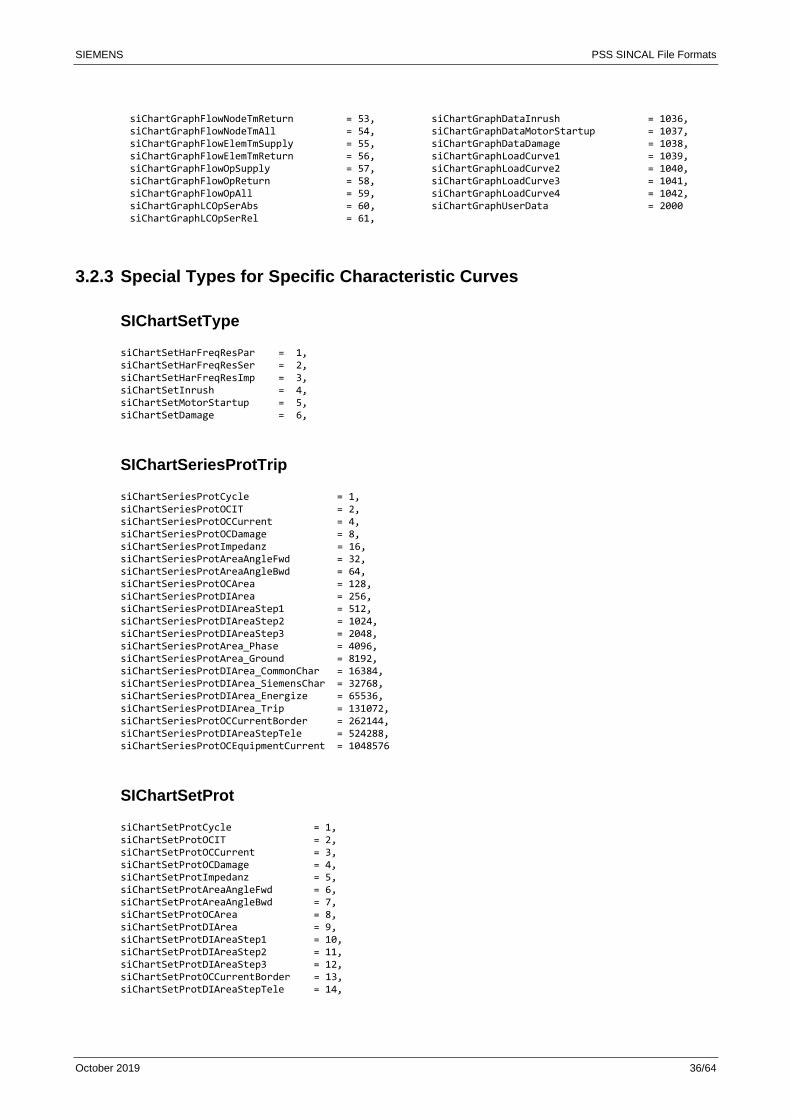
3.2.3 Special Types for Specific Characteristic Curves
SIChartSetType
siChartSetHarFreqResPar = 1, siChartSetHarFreqResSer = 2, siChartSetHarFreqResImp = 3, siChartSetInrush = 4, siChartSetMotorStartup = 5, siChartSetDamage = 6,
SIChartSeriesProtTrip
siChartSeriesProtCycle = 1, siChartSeriesProtOCIT = 2, siChartSeriesProtOCCurrent = 4, siChartSeriesProtOCDamage = 8, siChartSeriesProtImpedanz = 16, siChartSeriesProtAreaAngleFwd = 32, siChartSeriesProtAreaAngleBwd = 64, siChartSeriesProtOCArea = 128, siChartSeriesProtDIArea = 256, siChartSeriesProtDIAreaStep1 = 512, siChartSeriesProtDIAreaStep2 = 1024, siChartSeriesProtDIAreaStep3 = 2048, siChartSeriesProtArea_Phase = 4096, siChartSeriesProtArea_Ground = 8192, siChartSeriesProtDIArea_CommonChar = 16384, siChartSeriesProtDIArea_SiemensChar = 32768, siChartSeriesProtDIArea_Energize = 65536, siChartSeriesProtDIArea_Trip = 131072, siChartSeriesProtOCCurrentBorder = 262144, siChartSeriesProtDIAreaStepTele = 524288, siChartSeriesProtOCEquipmentCurrent = 1048576
SIChartSetProt
siChartSetProtCycle = 1, siChartSetProtOCIT = 2, siChartSetProtOCCurrent = 3, siChartSetProtOCDamage = 4, siChartSetProtImpedanz = 5, siChartSetProtAreaAngleFwd = 6, siChartSetProtAreaAngleBwd = 7, siChartSetProtOCArea = 8, siChartSetProtDIArea = 9, siChartSetProtDIAreaStep1 = 10, siChartSetProtDIAreaStep2 = 11, siChartSetProtDIAreaStep3 = 12, siChartSetProtOCCurrentBorder = 13, siChartSetProtDIAreaStepTele = 14,
SIEMENS PSS SINCAL File Formats
October 2019 37/64
siChartSetProtArea_Phase = 16, siChartSetProtArea_Ground = 32, siChartSetProtDIArea_CommonChar = 64, siChartSetProtDIArea_SiemensChar = 128, siChartSetProtDIArea_Energize = 256, siChartSetProtDIArea_Trip = 512
SIChartSeriesAddData
siChartSeriesAddData_1ST_ADD_RATING = 1, siChartSeriesAddData_2ND_ADD_RATING = 2, siChartSeriesAddData_3RD_ADD_RATING = 4, siChartSeriesAddData_RPH = 16, siChartSeriesAddData_SPH = 32, siChartSeriesAddData_TPH = 64
SIChartSeriesFlow
siChartSeriesFlowPressureRelBar = 1, siChartSeriesFlowPressureAbsBar = 2, siChartSeriesFlowHeightMeter = 4, siChartSeriesFlowTemprature = 8, siChartSeriesFlowSteamPressureRel = 16, siChartSeriesFlowSteamPressureAbs = 32, siChartSeriesFlowPressureRelMeter = 64, siChartSeriesFlowPressureAbsMeter = 128, siChartSeriesFlowHeightBar = 256, siChartSeriesFlowDistance = 512, siChartSeriesFlowNodeID = 1024, siChartSeriesFlowNo = 2048, siChartSeriesFlowPressureRelHeatBar = 4096, siChartSeriesFlowPressureAbsHeatBar = 8192, siChartSeriesFlowHeightHeatMeter = 16384, siChartSeriesFlowHeightHeatBar = 32768, siChartSeriesFlowPressureRelBarEx = 65536, siChartSeriesFlowPressureAbsBarEx = 131072, siChartSeriesFlowHeightMeterEx = 262144, siChartSeriesFlowTempratureEx = 524288, siChartSeriesFlowSteamPressureRelEx = 1048576, siChartSeriesFlowSteamPressureAbsEx = 2097152, siChartSeriesFlowPressureRelMeterEx = 4194304, siChartSeriesFlowPressureAbsMeterEx = 8388608, siChartSeriesFlowHeightBarEx = 16777216, siChartSeriesFlowDistanceEx = 33554432, siChartSeriesFlowNodeIDEx = 67108864, siChartSeriesFlowNoEx = 134217728, siChartSeriesFlowPressureRelHeatBarEx = 268435456, siChartSeriesFlowPressureAbsHeatBarEx = 536870912, siChartSeriesFlowHeightHeatMeterEx = 1073741824, siChartSeriesFlowHeightHeatBarEx = 2147483648
siChartSeriesFlowOPBehaviour
siChartSeriesFlowOPBehaviour_PressureRelMeter = 1, siChartSeriesFlowOPBehaviour_PressureRelBar1 = 2, siChartSeriesFlowOPBehaviour_PressureRelBar2 = 4, siChartSeriesFlowOPBehaviour_PressureRelBar3 = 8, siChartSeriesFlowOPBehaviour_PressureRelBar1Ex = 16, siChartSeriesFlowOPBehaviour_PressureRelBar2Ex = 32, siChartSeriesFlowOPBehaviour_PressureRelBar3Ex = 64, siChartSeriesFlowOPBehaviour_FlowM3 = 128, siChartSeriesFlowOPBehaviour_FlowMN3 = 256, siChartSeriesFlowOPBehaviour_FlowLS = 512, siChartSeriesFlowOPBehaviour_FlowTH = 1024,

SIEMENS PSS SINCAL File Formats
October 2019 38/64
siChartSeriesFlowOPBehaviour_FlowMW = 2048,
SIChartSeriesFlowGeo
siChartSeriesFlowGeoWTMeter = 1, siChartSeriesFlowGeoWTVolume = 2, siChartSeriesFlowGeoFlowLS = 4, siChartSeriesFlowGeoFlowTH = 8, siChartSeriesFlowGeoFlowMW = 16, siChartSeriesFlowGeoFlowMN3 = 32, siChartSeriesFlowGeoFlowM3 = 64, siChartSeriesFlowGeoFlow = 128, siChartSeriesFlowGeoPressureRel = 256,
siChartSeriesHarmonic
siChartSeriesHarVoltage_Min = 1, siChartSeriesHarVoltage_Max = 2
SIChartSeriesLoadCurve
siChartSeriesLCNodeVoltage = 1, siChartSeriesLCNodeActivePower = 2, siChartSeriesLCNodeReactivePower = 4, siChartSeriesLCElemUtilization = 8, siChartSeriesLCElemActivePower = 16, siChartSeriesLCElemReactivePower = 32, siChartSeriesLCNetLosses = 64, siChartSeriesLCNetEnergy = 128, siChartSeriesLCGeneralFactor = 256, siChartSeriesLCGeneralPower = 512, siChartSeriesLCOpSerAbsP = 1024, siChartSeriesLCOpSerAbsQ = 2048, siChartSeriesLCOpSerRel = 4096, siChartSeriesLCEnergy = 8192, siChartSeriesLCOpSerRelP = 16384, siChartSeriesLCOpSerRelQ = 32768,
SIChartSeriesLFIncSer
siChartSeriesLFIncElemUtilization = 1, siChartSeriesLFIncActualPower = 2, siChartSeriesLFIncSecurePower = 4, siChartSeriesLFIncSeriesAbsP = 8, siChartSeriesLFIncSeriesAbsQ = 16, siChartSeriesLFIncSeriesRel = 32, siChartSeriesLFIncSeriesRelP = 64, siChartSeriesLFIncSeriesRelQ = 128,
SIChartSeriesLCViolation
siChartSeriesLCViolationUmin = 1, siChartSeriesLCViolationUmax = 2, siChartSeriesLCViolationImax = 4, siChartSeriesLCViolationSum = 8,
SIEMENS PSS SINCAL File Formats
October 2019 39/64
SIChartSeriesLFVoltageCurve
siChartSeriesLFVoltageCurveP = 1, siChartSeriesLFVoltageCurveQ = 2, siChartSeriesLFVoltageCurveU = 4, siChartSeriesLFVoltageCurveNodeID = 8, siChartSeriesLFVoltageCurveDistance = 16, siChartSeriesLFVoltageCurveUmin = 32, siChartSeriesLFVoltageCurveNodeIDUmin = 64, siChartSeriesLFVoltageCurveR = 128, siChartSeriesLFVoltageCurveX = 256, siChartSeriesLFVoltageCurveZ = 512, siChartSeriesLFVoltageCurvePhi = 1024, siChartSeriesLFVoltageCurveP_RPH = 2048, siChartSeriesLFVoltageCurveP_SPH = 4096, siChartSeriesLFVoltageCurveP_TPH = 8192, siChartSeriesLFVoltageCurveQ_RPH = 16384, siChartSeriesLFVoltageCurveQ_SPH = 32768, siChartSeriesLFVoltageCurveQ_TPH = 65536, siChartSeriesLFVoltageCurveU_RPH = 131072, siChartSeriesLFVoltageCurveU_SPH = 262144, siChartSeriesLFVoltageCurveU_TPH = 524288, siChartSeriesLFVoltageCurveU_RSPH = 1048576, siChartSeriesLFVoltageCurveU_STPH = 2097152, siChartSeriesLFVoltageCurveU_TRPH = 4194304, siChartSeriesLFVoltageCurveI = 8388608, siChartSeriesLFVoltageCurveI_RPH = 16777216, siChartSeriesLFVoltageCurveI_SPH = 33554432, siChartSeriesLFVoltageCurveI_TPH = 67108864, siChartSeriesLFVoltageCurveIIb = 134217728, siChartSeriesLFVoltageCurveIIb_RPH = 268435456, siChartSeriesLFVoltageCurveIIb_SPH = 536870912, siChartSeriesLFVoltageCurveIIb_TPH = 1073741824
SIChartSeriesLFPVBehaviour
siChartSeriesLFPVBehaviourNodeID = 1, siChartSeriesLFPVBehaviourP_U = 16, siChartSeriesLFPVBehaviourP_U_RPH = 32, siChartSeriesLFPVBehaviourP_U_SPH = 64, siChartSeriesLFPVBehaviourP_U_TPH = 128, siChartSeriesLFPVBehaviourQ_U = 256, siChartSeriesLFPVBehaviourQ_U_RPH = 512, siChartSeriesLFPVBehaviourQ_U_SPH = 1024, siChartSeriesLFPVBehaviourQ_U_TPH = 2048, siChartSeriesLFPVBehaviourP = 4096, siChartSeriesLFPVBehaviourP_RPH = 8192, siChartSeriesLFPVBehaviourP_SPH = 16384, siChartSeriesLFPVBehaviourP_TPH = 32768, siChartSeriesLFPVBehaviourQ = 65536, siChartSeriesLFPVBehaviourQ_RPH = 131072, siChartSeriesLFPVBehaviourQ_SPH = 262144, siChartSeriesLFPVBehaviourQ_TPH = 524288,
SIChartSeriesTapZoneEvaluation
siChartSeriesTapZoneEvalDistance = 1, siChartSeriesTapZoneEvalNodeID = 2, siChartSeriesTapZoneEvalU_MinMax = 4, siChartSeriesTapZoneEvalMinU_P = 16, siChartSeriesTapZoneEvalMinU_P_RPH = 32, siChartSeriesTapZoneEvalMinU_P_SPH = 64, siChartSeriesTapZoneEvalMinU_P_TPH = 128, siChartSeriesTapZoneEvalMaxU_P = 256, siChartSeriesTapZoneEvalMaxU_P_RPH = 512,
SIEMENS PSS SINCAL File Formats
October 2019 40/64
siChartSeriesTapZoneEvalMaxU_P_SPH = 1024, siChartSeriesTapZoneEvalMaxU_P_TPH = 2048, siChartSeriesTapZoneEvalMinU_S = 4096, siChartSeriesTapZoneEvalMinU_S_RPH = 8192, siChartSeriesTapZoneEvalMinU_S_SPH = 16384, siChartSeriesTapZoneEvalMinU_S_TPH = 32768, siChartSeriesTapZoneEvalMaxU_S = 65536, siChartSeriesTapZoneEvalMaxU_S_RPH = 131072, siChartSeriesTapZoneEvalMaxU_S_SPH = 262144, siChartSeriesTapZoneEvalMaxU_S_TPH = 524288,
SIChartSeriesProtectionCurve
siChartSeriesProtectionCurveNodeValue = 1, siChartSeriesProtectionCurveNodeID = 2, siChartSeriesProtectionCurveNo = 4, siChartSeriesProtectionCurveProtLocID = 8, siChartSeriesProtectionCurveX = 16, siChartSeriesProtectionCurveY = 32, siChartSeriesProtectionCurveXY = 64, siChartSeriesProtectionCurveProtDirX = 128, siChartSeriesProtectionCurveProtX = 256, siChartSeriesProtectionCurveProtY = 512,
SIChartSeriesAsynchronousMachine
siChartSeriesNEMA_Speed = 1, siChartSeriesNEMA_Current = 2, siChartSeriesNEMA_Efficiency = 4, siChartSeriesNEMA_Torque = 8, siChartSeriesASM_Speed = 16, siChartSeriesASM_TorqueM = 32, siChartSeriesASM_TorqueL = 64, siChartSeriesASM_IStart = 128, siChartSeriesMOTNode_Time = 256, siChartSeriesMOTNode_U = 512, siChartSeriesMOTNode_P = 1024, siChartSeriesMOTNode_Q = 2048,
SIEMENS PSS SINCAL File Formats
October 2019 41/64
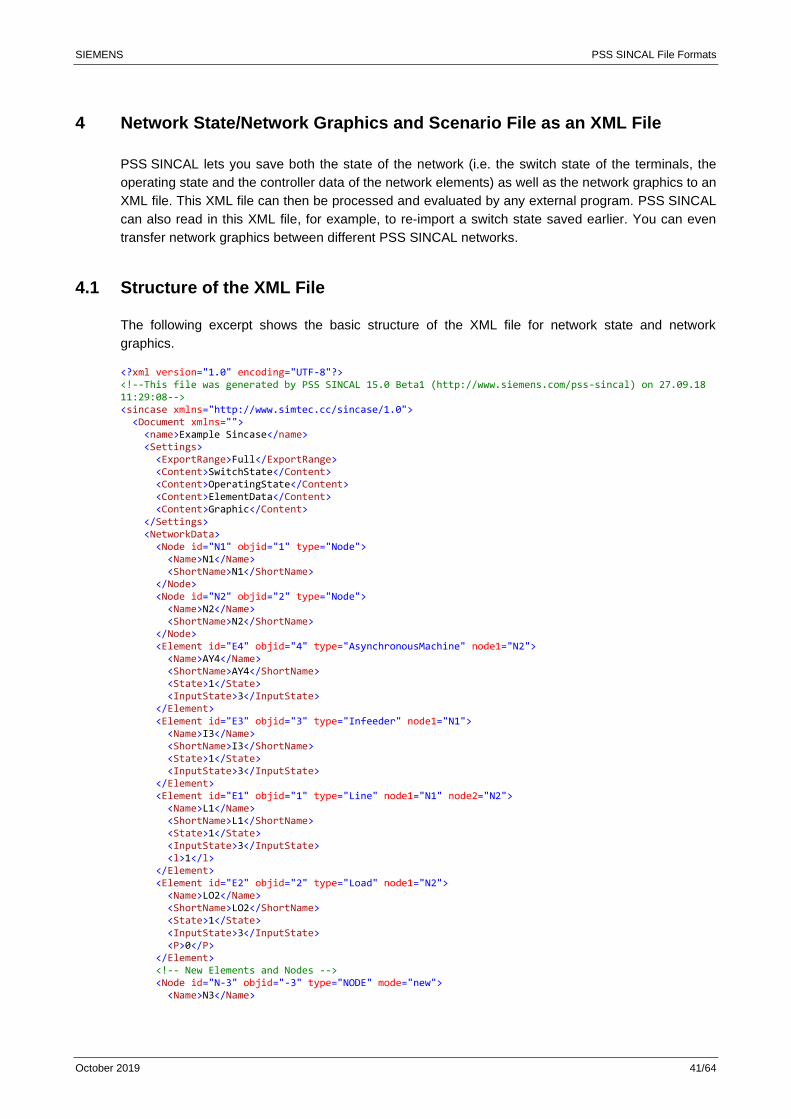
4 Network State/Network Graphics and Scenario File as an XML File
PSS SINCAL lets you save both the state of the network (i.e. the switch state of the terminals, the
operating state and the controller data of the network elements) as well as the network graphics to an
XML file. This XML file can then be processed and evaluated by any external program. PSS SINCAL
can also read in this XML file, for example, to re-import a switch state saved earlier. You can even
transfer network graphics between different PSS SINCAL networks.
4.1 Structure of the XML File
The following excerpt shows the basic structure of the XML file for network state and network
graphics.
<?xml version="1.0" encoding="UTF-8"?> <!--This file was generated by PSS SINCAL 15.0 Beta1 (http://www.siemens.com/pss-sincal) on 27.09.18 11:29:08--> <sincase xmlns="http://www.simtec.cc/sincase/1.0"> <Document xmlns=""> <name>Example Sincase</name> <Settings> <ExportRange>Full</ExportRange> <Content>SwitchState</Content> <Content>OperatingState</Content> <Content>ElementData</Content> <Content>Graphic</Content> </Settings> <NetworkData> <Node id="N1" objid="1" type="Node"> <Name>N1</Name> <ShortName>N1</ShortName> </Node> <Node id="N2" objid="2" type="Node"> <Name>N2</Name> <ShortName>N2</ShortName> </Node> <Element id="E4" objid="4" type="AsynchronousMachine" node1="N2"> <Name>AY4</Name> <ShortName>AY4</ShortName> <State>1</State> <InputState>3</InputState> </Element> <Element id="E3" objid="3" type="Infeeder" node1="N1"> <Name>I3</Name> <ShortName>I3</ShortName> <State>1</State> <InputState>3</InputState> </Element> <Element id="E1" objid="1" type="Line" node1="N1" node2="N2"> <Name>L1</Name> <ShortName>L1</ShortName> <State>1</State> <InputState>3</InputState> <l>1</l> </Element> <Element id="E2" objid="2" type="Load" node1="N2"> <Name>LO2</Name> <ShortName>LO2</ShortName> <State>1</State> <InputState>3</InputState> <P>0</P> </Element> <!-- New Elements and Nodes --> <Node id="N-3" objid="-3" type="NODE" mode="new"> <Name>N3</Name>
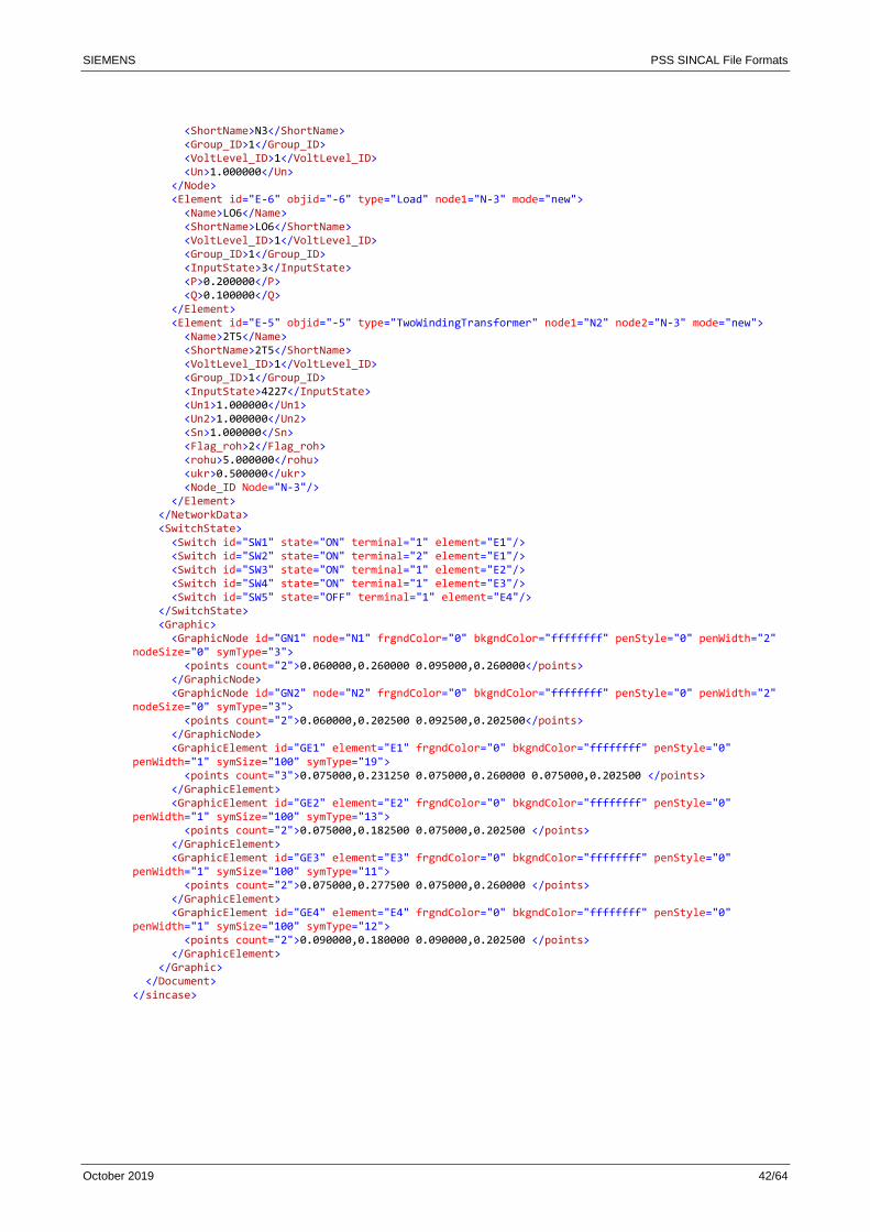
SIEMENS PSS SINCAL File Formats
October 2019 42/64
<ShortName>N3</ShortName> <Group_ID>1</Group_ID> <VoltLevel_ID>1</VoltLevel_ID> <Un>1.000000</Un> </Node> <Element id="E-6" objid="-6" type="Load" node1="N-3" mode="new"> <Name>LO6</Name> <ShortName>LO6</ShortName> <VoltLevel_ID>1</VoltLevel_ID> <Group_ID>1</Group_ID> <InputState>3</InputState> <P>0.200000</P> <Q>0.100000</Q> </Element> <Element id="E-5" objid="-5" type="TwoWindingTransformer" node1="N2" node2="N-3" mode="new"> <Name>2T5</Name> <ShortName>2T5</ShortName> <VoltLevel_ID>1</VoltLevel_ID> <Group_ID>1</Group_ID> <InputState>4227</InputState> <Un1>1.000000</Un1> <Un2>1.000000</Un2> <Sn>1.000000</Sn> <Flag_roh>2</Flag_roh> <rohu>5.000000</rohu> <ukr>0.500000</ukr> <Node_ID Node="N-3"/> </Element> </NetworkData> <SwitchState> <Switch id="SW1" state="ON" terminal="1" element="E1"/> <Switch id="SW2" state="ON" terminal="2" element="E1"/> <Switch id="SW3" state="ON" terminal="1" element="E2"/> <Switch id="SW4" state="ON" terminal="1" element="E3"/> <Switch id="SW5" state="OFF" terminal="1" element="E4"/> </SwitchState> <Graphic> <GraphicNode id="GN1" node="N1" frgndColor="0" bkgndColor="ffffffff" penStyle="0" penWidth="2" nodeSize="0" symType="3"> <points count="2">0.060000,0.260000 0.095000,0.260000</points> </GraphicNode> <GraphicNode id="GN2" node="N2" frgndColor="0" bkgndColor="ffffffff" penStyle="0" penWidth="2" nodeSize="0" symType="3"> <points count="2">0.060000,0.202500 0.092500,0.202500</points> </GraphicNode> <GraphicElement id="GE1" element="E1" frgndColor="0" bkgndColor="ffffffff" penStyle="0" penWidth="1" symSize="100" symType="19"> <points count="3">0.075000,0.231250 0.075000,0.260000 0.075000,0.202500 </points> </GraphicElement> <GraphicElement id="GE2" element="E2" frgndColor="0" bkgndColor="ffffffff" penStyle="0" penWidth="1" symSize="100" symType="13"> <points count="2">0.075000,0.182500 0.075000,0.202500 </points> </GraphicElement> <GraphicElement id="GE3" element="E3" frgndColor="0" bkgndColor="ffffffff" penStyle="0" penWidth="1" symSize="100" symType="11"> <points count="2">0.075000,0.277500 0.075000,0.260000 </points> </GraphicElement> <GraphicElement id="GE4" element="E4" frgndColor="0" bkgndColor="ffffffff" penStyle="0" penWidth="1" symSize="100" symType="12"> <points count="2">0.090000,0.180000 0.090000,0.202500 </points> </GraphicElement> </Graphic> </Document> </sincase>
SIEMENS PSS SINCAL File Formats
October 2019 43/64
4.1.1 Document
This element is the container for the network state and the network graphics.
<Document> <name>Example Sincase</name> <Settings> 26 </Settings> <NetworkData> 26 </NetworkData> <SwitchState> 26 </SwitchState> <Graphic> 26 </Graphic> </Document>
Elements
• name:
Name of the network.
• Settings:
Data in the XML file.
• NetworkData:
Network topology with all the nodes and network elements.
• SwitchState:
Switch state of the network.
• Graphic:
Graphic appearance of the network.
It can contain the graphics for nodes and network elements.
4.1.2 Settings
This element describes the data in the XML file.
<Settings> <ExportRange>Full</ExportRange> <Content>SwitchState</Content> <Content>OperatingState</Content> <Content>ElementData</Content> <Content>Graphic</Content> </Settings>
Elements
• ExportRange:
Describes whether the topology of the networks is stored completely or in reduced form.
Two values are possible:
o Full: Each node and each element are exported to the XML file.
o Reduced: Only elements and nodes that have open switches, are out of operation, or are
selected in the view are exported to the XML file.
• Content:
Can occur more than once for any contents exported.
The current version has the following values:
SIEMENS PSS SINCAL File Formats
October 2019 44/64
o SwitchState: The switch state is exported (see SwitchState).
o OperatingState: The element state is exported. There is an entry for whether the element is
out of operation or not (see State of Element).
o Transformer-Controller: The transformer controller data is exported.
o ElementData: Input data of elements and nodes are exported.
o Graphic: The graphics for the current network view is exported (see Graphic).
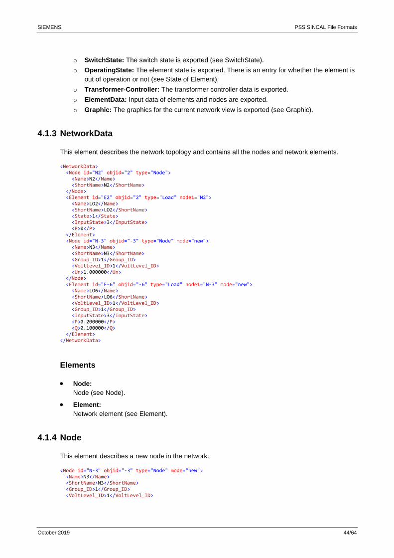
4.1.3 NetworkData
This element describes the network topology and contains all the nodes and network elements.
<NetworkData> <Node id="N2" objid="2" type="Node"> <Name>N2</Name> <ShortName>N2</ShortName> </Node> <Element id="E2" objid="2" type="Load" node1="N2"> <Name>LO2</Name> <ShortName>LO2</ShortName> <State>1</State> <InputState>3</InputState> <P>0</P> </Element> <Node id="N-3" objid="-3" type="Node" mode="new"> <Name>N3</Name> <ShortName>N3</ShortName> <Group_ID>1</Group_ID> <VoltLevel_ID>1</VoltLevel_ID> <Un>1.000000</Un> </Node> <Element id="E-6" objid="-6" type="Load" node1="N-3" mode="new"> <Name>LO6</Name> <ShortName>LO6</ShortName> <VoltLevel_ID>1</VoltLevel_ID> <Group_ID>1</Group_ID> <InputState>3</InputState> <P>0.200000</P> <Q>0.100000</Q> </Element> </NetworkData>
Elements
• Node:
Node (see Node).
• Element:
Network element (see Element).
4.1.4 Node
This element describes a new node in the network.
<Node id="N-3" objid="-3" type="Node" mode="new"> <Name>N3</Name> <ShortName>N3</ShortName> <Group_ID>1</Group_ID> <VoltLevel_ID>1</VoltLevel_ID>

SIEMENS PSS SINCAL File Formats
October 2019 45/64
<Un>1.000000</Un> </Node>
Attributes
• id:
A unique sequence of characters for identification in the XML file.
• objId:
Primary key for the node in the network database.
• type:
Object type for the node.
• mode:
Mode "new" indicates that this is a new node.
• Database fields (e.g.: Un):
If the XML tag names correspond to a database field of the "Node" table, the values are
transferred.
Elements
• Name:
Name of the node.
• ShortName:
Short name of the node.
4.1.5 Element
This element describes a new network element.
<Element id="E-5" objid="-5" type="TwoWindingTransformer" node1="N2" node2="N-3" mode="new"> <Name>2T5</Name> <ShortName>2T5</ShortName> <VoltLevel_ID>1</VoltLevel_ID> <Group_ID>1</Group_ID> <InputState>4227</InputState> <Un1>1.000000</Un1> <Un2>1.000000</Un2> <Sn>1.000000</Sn> <Flag_roh>2</Flag_roh> <rohu>5.000000</rohu> <ukr>0.500000</ukr> <Node_ID Node="N-3"/> </Element>
Attributes
• id:
A unique sequence of characters for identification in the XML file.
• objId:
Primary key for the network element in the network database.
SIEMENS PSS SINCAL File Formats
October 2019 46/64
• type:
Object type for the element.
• node1, node2, node3:
Nodes of the element with their unique IDs in the XML file.
Depending on type of the element, you can have node2 and node3 in addition to node1.
• mode:
Mode "new" indicates that this is a new element.
• Database fields (e.g.: P, Q):
If the XML tag names correspond to a database field of the "Element" table, the values are
transferred.
Elements
• Name:
Name of the element.
• ShortName:
Short name of the element.
• State (optional):
Operating state for the element.
Two values are possible:
o 0: Out of operation
o 1: In operation
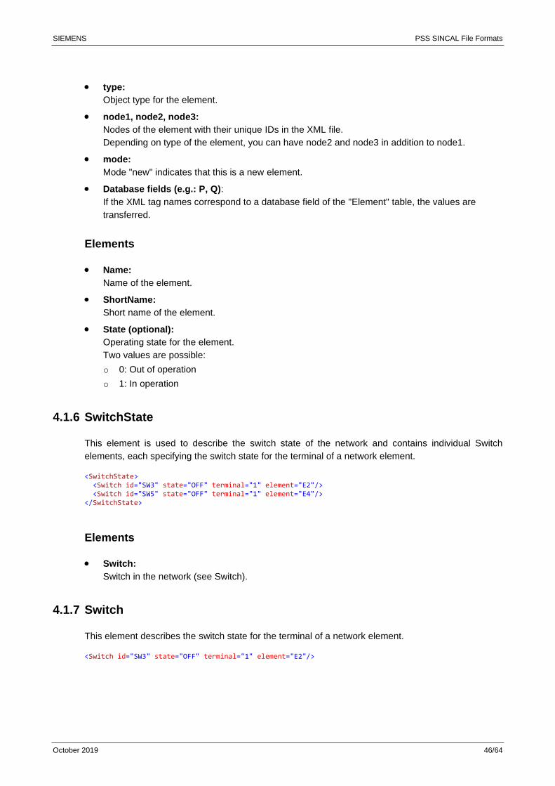
4.1.6 SwitchState
This element is used to describe the switch state of the network and contains individual Switch
elements, each specifying the switch state for the terminal of a network element.
<SwitchState> <Switch id="SW3" state="OFF" terminal="1" element="E2"/> <Switch id="SW5" state="OFF" terminal="1" element="E4"/> </SwitchState>
Elements
• Switch:
Switch in the network (see Switch).
4.1.7 Switch
This element describes the switch state for the terminal of a network element.
<Switch id="SW3" state="OFF" terminal="1" element="E2"/>
SIEMENS PSS SINCAL File Formats
October 2019 47/64
Attributes
• id:
A unique sequence of characters for identification in the XML file.
• state:
Switch state.
Two values are possible:
o OFF: The switch is open.
o ON: The switch is closed.
• terminal:
Terminal of the element containing the switch.
• element:
Element containing the switch.
This attribute is the unique ID of the element in the XML file.
4.1.8 Graphic
This element contains the graphic attributes for nodes and network elements.
<Graphic> <GraphicNode id="GN1" node="N1" frgndColor="0" bkgndColor="0" penStyle="0" penWidth="3" nodeSize="3" symType="1"> <points count="2">0.165000,0.232500 0.165000,0.232500</points> </GraphicNode> <GraphicElement id="GE1" element="E1" frgndColor="0" bkgndColor="-1" penStyle="0" penWidth="1" symSize="100" symType="12"> <points count="2">0.165000,0.208000 0.165000,0.232500 </points> </GraphicElement> </Graphic>
Elements
• GraphicNode:
Graphic appearance of a network node.
• GraphicElement:
Graphic appearance of a network element.
4.1.9 GraphicNode/GraphicElement
These elements describe the graphic appearance of network nodes and network elements.
<GraphicNode id="GN1" node="N1" frgndColor="0" bkgndColor="0" penStyle="0" penWidth="3" nodeSize="3" symType="1"> <points count="2">0.165000,0.232500 0.165000,0.232500</points> </GraphicNode> <GraphicElement id="GE1" element="E1" frgndColor="0" bkgndColor="-1" penStyle="0" penWidth="1" symSize="100" symType="12"> <points count="2">0.165000,0.208000 0.165000,0.232500 </points> </GraphicElement>
SIEMENS PSS SINCAL File Formats
October 2019 48/64
Attributes
• id:
A unique sequence of characters for identification in the XML file.
• node/element:
Refers to the node or the network element defining the graphic form.
The attribute is the unique ID of the node or network element in the XML file.
• frgndColor:
Line color of the graphic node or graphic element with a hexadecimal RGB color value.
• bkgndColor:
Background color of the graphic node or graphic element with a hexadecimal RGB color value.
• penStyle:
Line type.
The line type is encoded as follows:
0: Straight line
1: Small dotted
2: Dotted
3: Straight line – point – straight line
4: Straight line – point – point – straight line
• penWidth:
Line width.
The line width is a multiple of the internal basic unit of 0.25 mm. This means the value for "1" for
line width is 0.25 mm.
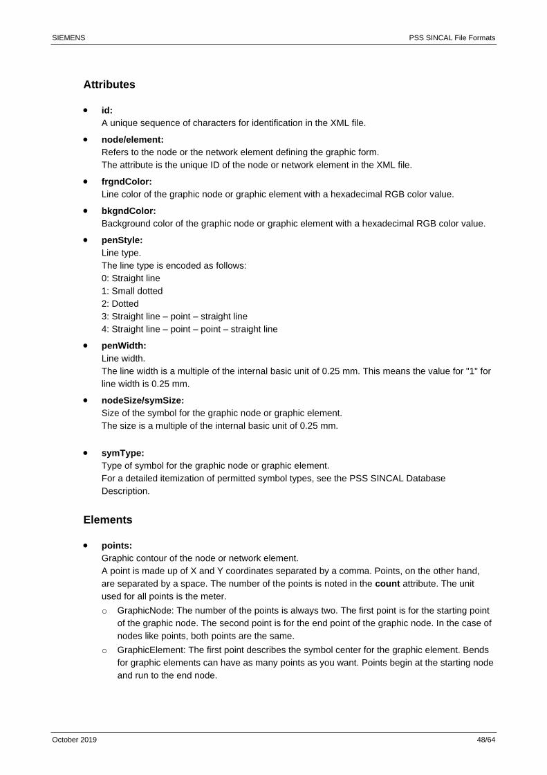
• nodeSize/symSize:
Size of the symbol for the graphic node or graphic element.
The size is a multiple of the internal basic unit of 0.25 mm.
• symType:
Type of symbol for the graphic node or graphic element.
For a detailed itemization of permitted symbol types, see the PSS SINCAL Database
Description.
Elements
• points:
Graphic contour of the node or network element.
A point is made up of X and Y coordinates separated by a comma. Points, on the other hand,
are separated by a space. The number of the points is noted in the count attribute. The unit
used for all points is the meter.
o GraphicNode: The number of the points is always two. The first point is for the starting point
of the graphic node. The second point is for the end point of the graphic node. In the case of
nodes like points, both points are the same.
o GraphicElement: The first point describes the symbol center for the graphic element. Bends
for graphic elements can have as many points as you want. Points begin at the starting node
and run to the end node.
SIEMENS PSS SINCAL File Formats
October 2019 49/64
5 Network Model with Admittance Matrix (NSN File)
The network model with admittance matrix contains the complete solved load flow of the network. It
represents a network snapshot (NSN), which can be used as the basis for dynamics simulation and
eigenvalue analysis.
The idea here is that calculating the load flow is not done with PSS NETOMAC, but with other
programs, and only the simulation is performed in the PSS NETOMAC core. This should solve
modelling problems in the load flow regarding controllers and convergence problems caused by
special network models.
For this purpose, the complete network dissolved by the load flow is described by a NSN file. It
contains the series admittances of the network models. The infeeders, consumers and losses are
represented by shunt admittances. For each node point of the network the the complex voltage
values in pu are present.
Please note the following when using a NSN file:
• The NSN file can only be used in eigenvalue analysis and stability simulation.
• The network models must be symmetrical.
5.1 Structure of the NSN File
The NSN file contains the following the data sections:
• Settings
• Nodes
• Branches
The following example shows the structure of the NSN file.
5.1.1 Settings
This data section contains the global parameters and appears at the beginning of the NSN file with
the identificator [Settings].
SIEMENS PSS SINCAL File Formats
October 2019 50/64
The following parameters are available:
• SBASE contains the reference power in MVA and is used to convert the admittances to powers.
5.1.2 Nodes
This data section starts with the identificator [Nodes]. All nodes of the network are listed here.
Column Variable Unit Default Remarks
1-6 Node number The node number must be unique. It is used to identify the node.
11-18 Node name Name of the node
23-43 Voltage – active part pu The node voltage corresponds to the result voltage of the load flow calculation without transformer base rotation.
44-64 Voltage – reactive part pu
5.1.3 Branches
This data section starts with the identificator [Branches]. It describes the admittance matrix of the
network.
Column Variable Unit Default Remarks
1-6 Branch number The branch number must be unique. It is used to identify the branch.
7-12 Node number 1 Node number of branch – terminal 1
13-18 Node number 2 Node number of branch – terminal 2. If empty, then it is a shunt branch.
23-30 Branch name Name of the branch
31-51 Admittance – active part pu The admittance entered here reflects the result of the load flow calculation. Negative admittances simulate feeds, positive admittances simulate consumptions. The admittances are related to the reference power SBASE.
52-72 Admittance – reactive part pu
73-93 Transformation – active part pu The transformation is output without transformer base rotation. It corresponds to the transformation (tap position) at the end of the load flow calculation.
94-114 Transformation – reactive part pu
Please note the following:
• Node elements (consumers, infeeders, etc.) are given the value 0 in the field "Node number 2".
This is used to model a shunt element to ground.
• Branch losses are simulated at the initial node and end node as shunt elements. They must be
written afterwards to the branch named "$CAP" like node elements.
5.2 Using the NSN File
The NSN file has the same name as the NET file. It can optionally be stored in the same directory as
the NET file or in the CTL directory.
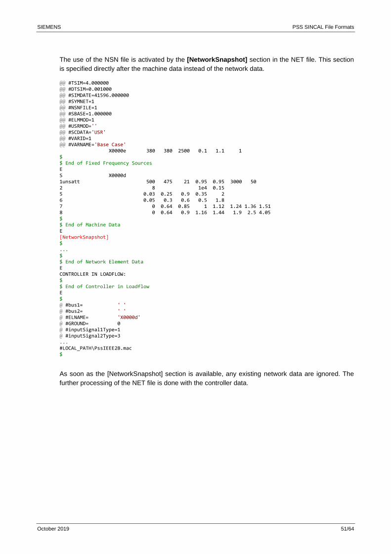
SIEMENS PSS SINCAL File Formats
October 2019 51/64
The use of the NSN file is activated by the [NetworkSnapshot] section in the NET file. This section
is specified directly after the machine data instead of the network data.
@@ #TSIM=4.000000 @@ #DTSIM=0.001000 @@ #SIMDATE=41596.000000 @@ #SYMNET=1 @@ #NSNFILE=1 @@ #SBASE=1.000000 @@ #ELMMOD=1 @@ #USRMOD='' @@ #SCDATA='USR' @@ #VARID=1 @@ #VARNAME='Base Case' X0000e 380 380 2500 0.1 1.1 1 $ $ End of Fixed Frequency Sources E S X0000d 1unsatt 500 475 21 0.95 0.95 3000 50 2 8 1e4 0.15 5 0.03 0.25 0.9 0.35 2 6 0.05 0.3 0.6 0.5 1.8 7 0 0.64 0.85 1 1.12 1.24 1.36 1.51 8 0 0.64 0.9 1.16 1.44 1.9 2.5 4.05 $ $ End of Machine Data E [NetworkSnapshot] $ ... $ $ End of Network Element Data E CONTROLLER IN LOADFLOW: $ $ End of Controller in Loadflow E $ @ #bus1= ' ' @ #bus2= ' ' @ #ELNAME= 'X0000d' @ #GROUND= 0 @ #inputSignal1Type=1 @ #inputSignal2Type=3 ... #LOCAL_PATH\PssIEEE2B.mac $
As soon as the [NetworkSnapshot] section is available, any existing network data are ignored. The
further processing of the NET file is done with the controller data.

SIEMENS PSS SINCAL File Formats
October 2019 52/64
6 Reliability Results in the XML Database
Probabilistic reliability calculations consist of a Calculation Part, which generates the component
failure combinations and models their sequence up to complete restoration of supply, and an
Analysis Part, which conducts a detailed analysis based on the calculated failure sequences. The
following figure gives an overview of the program structure of the reliability calculation.
The Calculation Part is to model the failure events in the power system under consideration and to
calculate the indices of the component failure combinations leading to a supply interruption. Those
indices are saved in a XML database.
This XML database is found in the PSS SINCAL network’s "REL" subdirectory and is the basis for all
PSS SINCAL's reliability evaluations. Any external program can read the XML database and use this
for individual evaluations and analyses.
6.1 Structure of the XML Database
The following excerpt shows the main XML database structure for the results of reliability
calculations.
<?xml version="1.0" encoding="ISO-8859-1"?> <Reliability> <Date TYP='start'>Wed Aug 26 09:02:14 2009</Date> <Info> <Database ID='0'>D:\SincalDB\Error\ZuVer_files\database.mdb</Database> <Object ID='1' DB='0' DBID='1' TYP='32' Name=''/> <Object ID='2' DB='0' DBID='1' TYP='6' Name='10 kV'/> <Object ID='3' DB='0' DBID='2' TYP='6' Name='Industrie'/> <Object ID='11' DB='0' DBID='1' TYP='86' Name='UMZ-A1'/> <Object ID='12' DB='0' DBID='2' TYP='86' Name='UMZ-A2'/>
Equipment reliability data
Network data
Analysis Part
• Selection of component failure combinations
• Analysis of component failure combinations
•
Sorted list
Sequence list
Table of results
Results File
XML failure combinations
database
Reliability results
PSS SINCAL Network Database
Calculation Part
• Data preparation
• Generation of component failure combinations
• State analysis
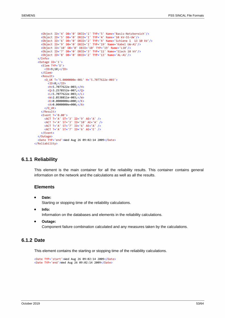
SIEMENS PSS SINCAL File Formats
October 2019 53/64
<Object ID='4' DB='0' DBID='1' TYP='5' Name='Basis-Netzbereich'/> <Object ID='5' DB='0' DBID='1' TYP='4' Name='10 kV-SS-UW'/> <Object ID='6' DB='0' DBID='2' TYP='4' Name='Schiene 1 13 10 kV'/> <Object ID='9' DB='0' DBID='1' TYP='19' Name='Kabel UW-A1'/> <Object ID='10' DB='0' DBID='10' TYP='19' Name='L10'/> <Object ID='7' DB='0' DBID='3' TYP='11' Name='Slack 10 kV'/> <Object ID='8' DB='0' DBID='2' TYP='13' Name='AL-A1'/> </Info> <Outage ID='1'> <Elem TYP='D'> <ID>9;10;</ID> </Elem> <Result> <O_UK T='5.0000000e-001' H='5.7077622e-003'> <ID>8;</ID> <H>5.7077622e-003;</H> <Q>3.2578552e-007;</Q> <L>5.7077622e-003;</L> <W>2.8538811e-003;</W> <K>0.0000000e+000;</K> <A>0.0000000e+000;</A> </O_UK> </Result> <Event T='0.00'> <ACT T='A' ST='3' ID='9' AE='A' /> <ACT T='A' ST='3' ID='10' AE='A' /> <ACT T='A' ST='7' ID='6' AE='A' /> <ACT T='A' ST='7' ID='6' AE='E' /> </Event> </Outage> <Date TYP='end'>Wed Aug 26 09:02:14 2009</Date> </Reliability>
6.1.1 Reliability
This element is the main container for all the reliability results. This container contains general
information on the network and the calculations as well as all the results.
Elements
• Date:
Starting or stopping time of the reliability calculations.
• Info:
Information on the databases and elements in the reliability calculations.
• Outage:
Component failure combination calculated and any measures taken by the calculations.
6.1.2 Date
This element contains the starting or stopping time of the reliability calculations.
<Date TYP='start'>Wed Aug 26 09:02:14 2009</Date> <Date TYP='end'>Wed Aug 26 09:02:14 2009</Date>
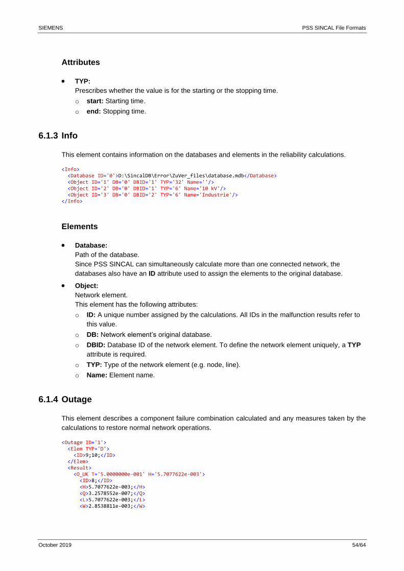
SIEMENS PSS SINCAL File Formats
October 2019 54/64
Attributes
• TYP:
Prescribes whether the value is for the starting or the stopping time.
o start: Starting time.
o end: Stopping time.
6.1.3 Info
This element contains information on the databases and elements in the reliability calculations.
<Info> <Database ID='0'>D:\SincalDB\Error\ZuVer_files\database.mdb</Database> <Object ID='1' DB='0' DBID='1' TYP='32' Name=''/> <Object ID='2' DB='0' DBID='1' TYP='6' Name='10 kV'/> <Object ID='3' DB='0' DBID='2' TYP='6' Name='Industrie'/> </Info>
Elements
• Database:
Path of the database.
Since PSS SINCAL can simultaneously calculate more than one connected network, the
databases also have an ID attribute used to assign the elements to the original database.
• Object:
Network element.
This element has the following attributes:
o ID: A unique number assigned by the calculations. All IDs in the malfunction results refer to
this value.
o DB: Network element’s original database.
o DBID: Database ID of the network element. To define the network element uniquely, a TYP
attribute is required.
o TYP: Type of the network element (e.g. node, line).
o Name: Element name.
6.1.4 Outage
This element describes a component failure combination calculated and any measures taken by the
calculations to restore normal network operations.
<Outage ID='1'> <Elem TYP='D'> <ID>9;10;</ID> </Elem> <Result> <O_UK T='5.0000000e-001' H='5.7077622e-003'> <ID>8;</ID> <H>5.7077622e-003;</H> <Q>3.2578552e-007;</Q> <L>5.7077622e-003;</L> <W>2.8538811e-003;</W>
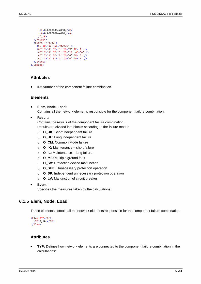
SIEMENS PSS SINCAL File Formats
October 2019 55/64
<K>0.0000000e+000;</K> <A>0.0000000e+000;</A> </O_UK> </Result> <Event T='0.00'> <SL ID='10' SL='0.995' /> <ACT T='A' ST='3' ID='9' AE='A' /> <ACT T='A' ST='3' ID='10' AE='A' /> <ACT T='A' ST='7' ID='6' AE='A' /> <ACT T='A' ST='7' ID='6' AE='E' /> </Event> </Outage>
Attributes
• ID: Number of the component failure combination.
Elements
• Elem, Node, Load:
Contains all the network elements responsible for the component failure combination.
• Result:
Contains the results of the component failure combination.
Results are divided into blocks according to the failure model:
o O_UK: Short independent failure
o O_UL: Long independent failure
o O_CM: Common Mode failure
o O_IK: Maintenance – short failure
o O_IL: Maintenance – long failure
o O_ME: Multiple ground fault
o O_SV: Protection device malfunction
o O_SUE: Unnecessary protection operation
o O_SP: Independent unnecessary protection operation
o O_LV: Malfunction of circuit breaker
• Event:
Specifies the measures taken by the calculations.
6.1.5 Elem, Node, Load
These elements contain all the network elements responsible for the component failure combination.
<Elem TYP='D'> <ID>9;10;</ID> </Elem>
Attributes
• TYP: Defines how network elements are connected to the component failure combination in the
calculations:
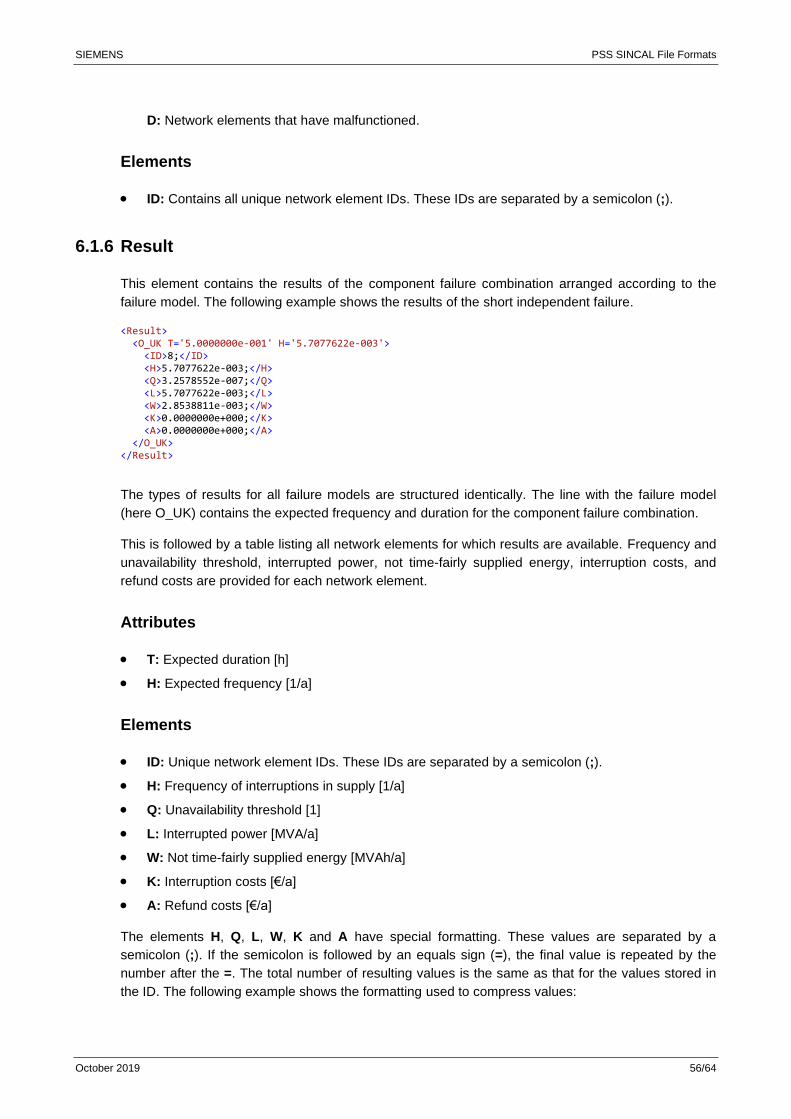
SIEMENS PSS SINCAL File Formats
October 2019 56/64
D: Network elements that have malfunctioned.
Elements
• ID: Contains all unique network element IDs. These IDs are separated by a semicolon (;).
6.1.6 Result
This element contains the results of the component failure combination arranged according to the
failure model. The following example shows the results of the short independent failure.
<Result> <O_UK T='5.0000000e-001' H='5.7077622e-003'> <ID>8;</ID> <H>5.7077622e-003;</H> <Q>3.2578552e-007;</Q> <L>5.7077622e-003;</L> <W>2.8538811e-003;</W> <K>0.0000000e+000;</K> <A>0.0000000e+000;</A> </O_UK> </Result>
The types of results for all failure models are structured identically. The line with the failure model
(here O_UK) contains the expected frequency and duration for the component failure combination.
This is followed by a table listing all network elements for which results are available. Frequency and
unavailability threshold, interrupted power, not time-fairly supplied energy, interruption costs, and
refund costs are provided for each network element.
Attributes
• T: Expected duration [h]
• H: Expected frequency [1/a]
Elements
• ID: Unique network element IDs. These IDs are separated by a semicolon (;).
• H: Frequency of interruptions in supply [1/a]
• Q: Unavailability threshold [1]
• L: Interrupted power [MVA/a]
• W: Not time-fairly supplied energy [MVAh/a]
• K: Interruption costs [€/a]
• A: Refund costs [€/a]
The elements H, Q, L, W, K and A have special formatting. These values are separated by a
semicolon (;). If the semicolon is followed by an equals sign (=), the final value is repeated by the
number after the =. The total number of resulting values is the same as that for the values stored in
the ID. The following example shows the formatting used to compress values:
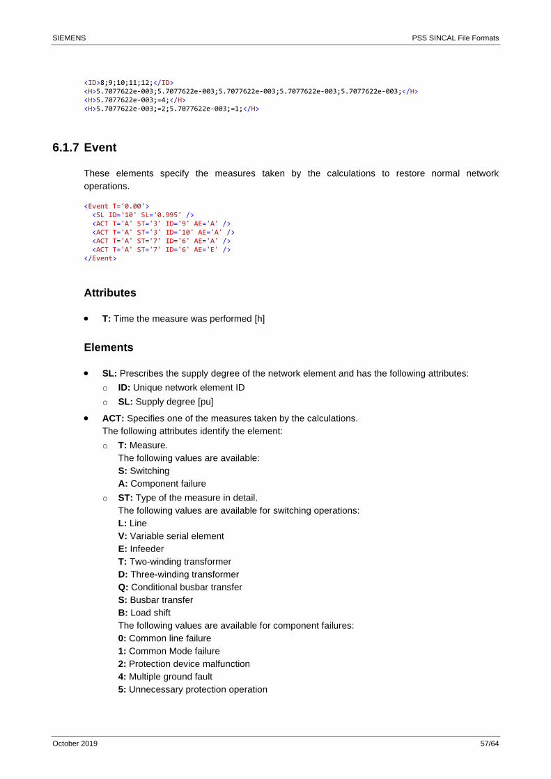
SIEMENS PSS SINCAL File Formats
October 2019 57/64
<ID>8;9;10;11;12;</ID> <H>5.7077622e-003;5.7077622e-003;5.7077622e-003;5.7077622e-003;5.7077622e-003;</H> <H>5.7077622e-003;=4;</H> <H>5.7077622e-003;=2;5.7077622e-003;=1;</H>
6.1.7 Event
These elements specify the measures taken by the calculations to restore normal network
operations.
<Event T='0.00'> <SL ID='10' SL='0.995' /> <ACT T='A' ST='3' ID='9' AE='A' /> <ACT T='A' ST='3' ID='10' AE='A' /> <ACT T='A' ST='7' ID='6' AE='A' /> <ACT T='A' ST='7' ID='6' AE='E' /> </Event>
Attributes
• T: Time the measure was performed [h]
Elements
• SL: Prescribes the supply degree of the network element and has the following attributes:
o ID: Unique network element ID
o SL: Supply degree [pu]
• ACT: Specifies one of the measures taken by the calculations.
The following attributes identify the element:
o T: Measure.
The following values are available:
S: Switching
A: Component failure
o ST: Type of the measure in detail.
The following values are available for switching operations:
L: Line
V: Variable serial element
E: Infeeder
T: Two-winding transformer
D: Three-winding transformer
Q: Conditional busbar transfer
S: Busbar transfer
B: Load shift
The following values are available for component failures:
0: Common line failure
1: Common Mode failure
2: Protection device malfunction
4: Multiple ground fault
5: Unnecessary protection operation

SIEMENS PSS SINCAL File Formats
October 2019 58/64
12: Malfunction of circuit breaker
13: Independent unnecessary protection operation
18: Short independent single failure
19: Long independent single failure
20: Short maintenance
21: Long maintenance
o ID: Unique ID of the network element.
o AE: Beginning or end of the measure.
The following values are available:
A: Beginning
E: End
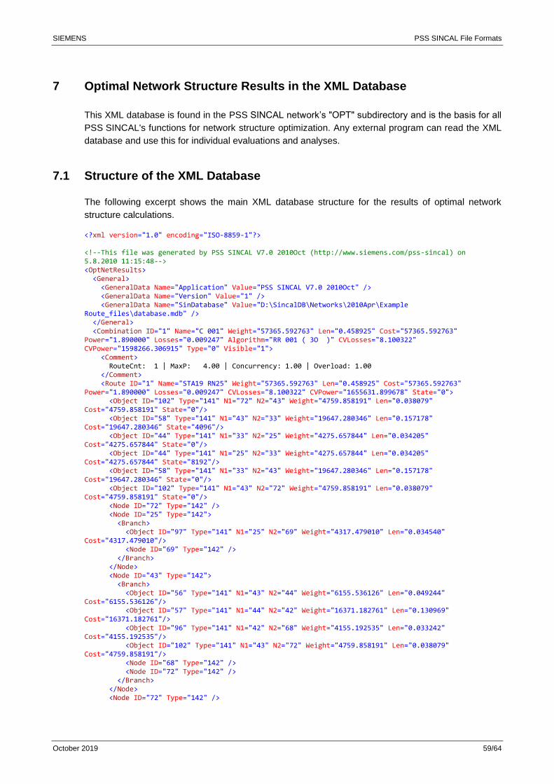
SIEMENS PSS SINCAL File Formats
October 2019 59/64
7 Optimal Network Structure Results in the XML Database
This XML database is found in the PSS SINCAL network’s "OPT" subdirectory and is the basis for all
PSS SINCAL's functions for network structure optimization. Any external program can read the XML
database and use this for individual evaluations and analyses.
7.1 Structure of the XML Database
The following excerpt shows the main XML database structure for the results of optimal network
structure calculations.
<?xml version="1.0" encoding="ISO-8859-1"?> <!--This file was generated by PSS SINCAL V7.0 2010Oct (http://www.siemens.com/pss-sincal) on 5.8.2010 11:15:48--> <OptNetResults> <General> <GeneralData Name="Application" Value="PSS SINCAL V7.0 2010Oct" /> <GeneralData Name="Version" Value="1" /> <GeneralData Name="SinDatabase" Value="D:\SincalDB\Networks\2010Apr\Example Route_files\database.mdb" /> </General> <Combination ID="1" Name="C 001" Weight="57365.592763" Len="0.458925" Cost="57365.592763" Power="1.890000" Losses="0.009247" Algorithm="RR 001 ( 3O )" CVLosses="8.100322" CVPower="1598266.306915" Type="0" Visible="1"> <Comment> RouteCnt: 1 | MaxP: 4.00 | Concurrency: 1.00 | Overload: 1.00 </Comment> <Route ID="1" Name="STA19 RN25" Weight="57365.592763" Len="0.458925" Cost="57365.592763" Power="1.890000" Losses="0.009247" CVLosses="8.100322" CVPower="1655631.899678" State="0"> <Object ID="102" Type="141" N1="72" N2="43" Weight="4759.858191" Len="0.038079" Cost="4759.858191" State="0"/> <Object ID="58" Type="141" N1="43" N2="33" Weight="19647.280346" Len="0.157178" Cost="19647.280346" State="4096"/> <Object ID="44" Type="141" N1="33" N2="25" Weight="4275.657844" Len="0.034205" Cost="4275.657844" State="0"/> <Object ID="44" Type="141" N1="25" N2="33" Weight="4275.657844" Len="0.034205" Cost="4275.657844" State="8192"/> <Object ID="58" Type="141" N1="33" N2="43" Weight="19647.280346" Len="0.157178" Cost="19647.280346" State="0"/> <Object ID="102" Type="141" N1="43" N2="72" Weight="4759.858191" Len="0.038079" Cost="4759.858191" State="0"/> <Node ID="72" Type="142" /> <Node ID="25" Type="142"> <Branch> <Object ID="97" Type="141" N1="25" N2="69" Weight="4317.479010" Len="0.034540" Cost="4317.479010"/> <Node ID="69" Type="142" /> </Branch> </Node> <Node ID="43" Type="142"> <Branch> <Object ID="56" Type="141" N1="43" N2="44" Weight="6155.536126" Len="0.049244" Cost="6155.536126"/> <Object ID="57" Type="141" N1="44" N2="42" Weight="16371.182761" Len="0.130969" Cost="16371.182761"/> <Object ID="96" Type="141" N1="42" N2="68" Weight="4155.192535" Len="0.033242" Cost="4155.192535"/> <Object ID="102" Type="141" N1="43" N2="72" Weight="4759.858191" Len="0.038079" Cost="4759.858191"/> <Node ID="68" Type="142" /> <Node ID="72" Type="142" /> </Branch> </Node> <Node ID="72" Type="142" />
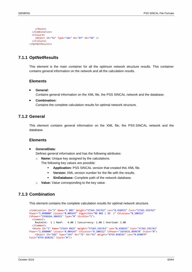
SIEMENS PSS SINCAL File Formats
October 2019 60/64
</Route> </Combination> <Closure> <Object ID="51" Type="141" N1="87" N2="94" /> </Closure> </OptNetResults>
7.1.1 OptNetResults
This element is the main container for all the optimum network structure results. This container
contains general information on the network and all the calculation results.
Elements
• General:
Contains general information on the XML file, the PSS SINCAL network and the database.
• Combination:
Contains the complete calculation results for optimal network structure.
7.1.2 General
This element contains general information on the XML file, the PSS SINCAL network and the
database.
Elements
• GeneralData:
Defines general information and has the following attributes:
o Name: Unique key assigned by the calculations.
The following key values are possible:
▪ Application: PSS SINCAL version that created this XML file.
▪ Version: XML version number for the file with the results.
▪ SinDatabase: Complete path of the network database.
o Value: Value corresponding to the key value.
7.1.3 Combination
This element contains the complete calculation results for optimal network structure.
<Combination ID="1" Name="C 001" Weight="57365.592763" Len="0.458925" Cost="57365.592763" Power="1.890000" Losses="0.009247" Algorithm="RR 001 ( 3O )" CVLosses="8.100322" CVPower="1598266.306915" Type="0" Visible="1"> <Comment> RouteCnt: 1 | MaxP: 4.00 | Concurrency: 1.00 | Overload: 1.00 </Comment> <Route ID="1" Name="STA19 RN25" Weight="57365.592763" Len="0.458925" Cost="57365.592763" Power="1.890000" Losses="0.009247" CVLosses="8.100322" CVPower="1655631.899678" State="0"> <Object ID="102" Type="141" N1="72" N2="43" Weight="4759.858191" Len="0.038079" Cost="4759.858191" State="0"/>
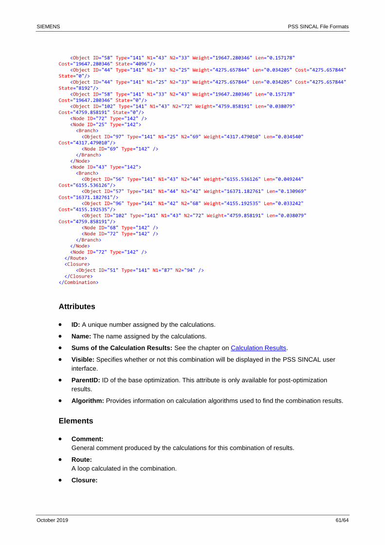
SIEMENS PSS SINCAL File Formats
October 2019 61/64
<Object ID="58" Type="141" N1="43" N2="33" Weight="19647.280346" Len="0.157178" Cost="19647.280346" State="4096"/> <Object ID="44" Type="141" N1="33" N2="25" Weight="4275.657844" Len="0.034205" Cost="4275.657844" State="0"/> <Object ID="44" Type="141" N1="25" N2="33" Weight="4275.657844" Len="0.034205" Cost="4275.657844" State="8192"/> <Object ID="58" Type="141" N1="33" N2="43" Weight="19647.280346" Len="0.157178" Cost="19647.280346" State="0"/> <Object ID="102" Type="141" N1="43" N2="72" Weight="4759.858191" Len="0.038079" Cost="4759.858191" State="0"/> <Node ID="72" Type="142" /> <Node ID="25" Type="142"> <Branch> <Object ID="97" Type="141" N1="25" N2="69" Weight="4317.479010" Len="0.034540" Cost="4317.479010"/> <Node ID="69" Type="142" /> </Branch> </Node> <Node ID="43" Type="142"> <Branch> <Object ID="56" Type="141" N1="43" N2="44" Weight="6155.536126" Len="0.049244" Cost="6155.536126"/> <Object ID="57" Type="141" N1="44" N2="42" Weight="16371.182761" Len="0.130969" Cost="16371.182761"/> <Object ID="96" Type="141" N1="42" N2="68" Weight="4155.192535" Len="0.033242" Cost="4155.192535"/> <Object ID="102" Type="141" N1="43" N2="72" Weight="4759.858191" Len="0.038079" Cost="4759.858191"/> <Node ID="68" Type="142" /> <Node ID="72" Type="142" /> </Branch> </Node> <Node ID="72" Type="142" /> </Route> <Closure> <Object ID="51" Type="141" N1="87" N2="94" /> </Closure> </Combination>
Attributes
• ID: A unique number assigned by the calculations.
• Name: The name assigned by the calculations.
• Sums of the Calculation Results: See the chapter on Calculation Results.
• Visible: Specifies whether or not this combination will be displayed in the PSS SINCAL user
interface.
• ParentID: ID of the base optimization. This attribute is only available for post-optimization
results.
• Algorithm: Provides information on calculation algorithms used to find the combination results.
Elements
• Comment:
General comment produced by the calculations for this combination of results.
• Route:
A loop calculated in the combination.
• Closure:
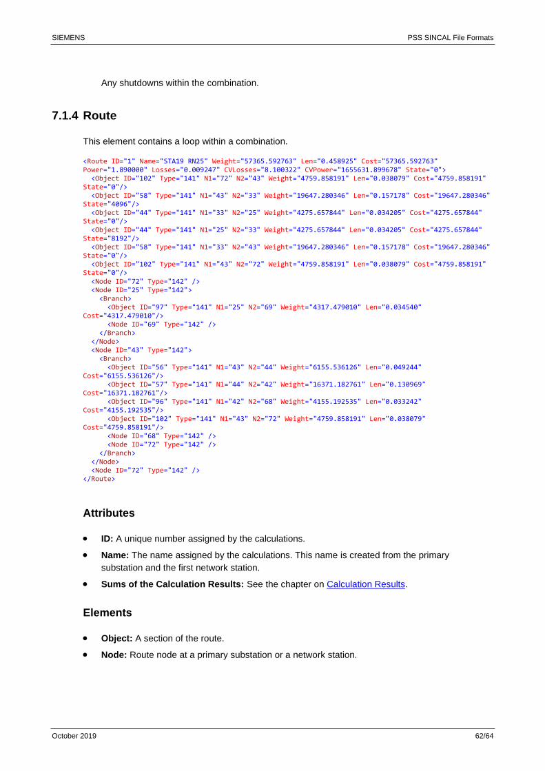
SIEMENS PSS SINCAL File Formats
October 2019 62/64
Any shutdowns within the combination.
7.1.4 Route
This element contains a loop within a combination.
<Route ID="1" Name="STA19 RN25" Weight="57365.592763" Len="0.458925" Cost="57365.592763" Power="1.890000" Losses="0.009247" CVLosses="8.100322" CVPower="1655631.899678" State="0"> <Object ID="102" Type="141" N1="72" N2="43" Weight="4759.858191" Len="0.038079" Cost="4759.858191" State="0"/> <Object ID="58" Type="141" N1="43" N2="33" Weight="19647.280346" Len="0.157178" Cost="19647.280346" State="4096"/> <Object ID="44" Type="141" N1="33" N2="25" Weight="4275.657844" Len="0.034205" Cost="4275.657844" State="0"/> <Object ID="44" Type="141" N1="25" N2="33" Weight="4275.657844" Len="0.034205" Cost="4275.657844" State="8192"/> <Object ID="58" Type="141" N1="33" N2="43" Weight="19647.280346" Len="0.157178" Cost="19647.280346" State="0"/> <Object ID="102" Type="141" N1="43" N2="72" Weight="4759.858191" Len="0.038079" Cost="4759.858191" State="0"/> <Node ID="72" Type="142" /> <Node ID="25" Type="142"> <Branch> <Object ID="97" Type="141" N1="25" N2="69" Weight="4317.479010" Len="0.034540" Cost="4317.479010"/> <Node ID="69" Type="142" /> </Branch> </Node> <Node ID="43" Type="142"> <Branch> <Object ID="56" Type="141" N1="43" N2="44" Weight="6155.536126" Len="0.049244" Cost="6155.536126"/> <Object ID="57" Type="141" N1="44" N2="42" Weight="16371.182761" Len="0.130969" Cost="16371.182761"/> <Object ID="96" Type="141" N1="42" N2="68" Weight="4155.192535" Len="0.033242" Cost="4155.192535"/> <Object ID="102" Type="141" N1="43" N2="72" Weight="4759.858191" Len="0.038079" Cost="4759.858191"/> <Node ID="68" Type="142" /> <Node ID="72" Type="142" /> </Branch> </Node> <Node ID="72" Type="142" /> </Route>
Attributes
• ID: A unique number assigned by the calculations.
• Name: The name assigned by the calculations. This name is created from the primary
substation and the first network station.
• Sums of the Calculation Results: See the chapter on Calculation Results.
Elements
• Object: A section of the route.
• Node: Route node at a primary substation or a network station.
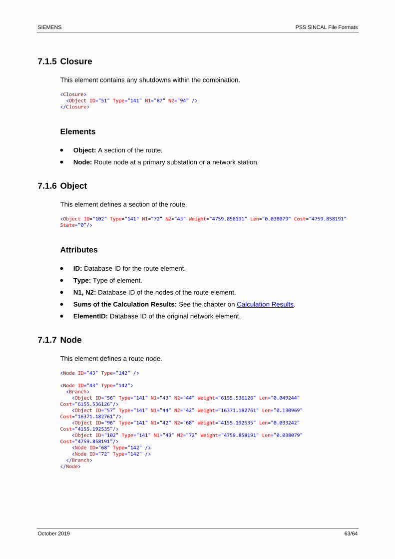
SIEMENS PSS SINCAL File Formats
October 2019 63/64
7.1.5 Closure
This element contains any shutdowns within the combination.
<Closure> <Object ID="51" Type="141" N1="87" N2="94" /> </Closure>
Elements
• Object: A section of the route.
• Node: Route node at a primary substation or a network station.
7.1.6 Object
This element defines a section of the route.
<Object ID="102" Type="141" N1="72" N2="43" Weight="4759.858191" Len="0.038079" Cost="4759.858191" State="0"/>
Attributes
• ID: Database ID for the route element.
• Type: Type of element.
• N1, N2: Database ID of the nodes of the route element.
• Sums of the Calculation Results: See the chapter on Calculation Results.
• ElementID: Database ID of the original network element.
7.1.7 Node
This element defines a route node.
<Node ID="43" Type="142" /> <Node ID="43" Type="142"> <Branch> <Object ID="56" Type="141" N1="43" N2="44" Weight="6155.536126" Len="0.049244" Cost="6155.536126"/> <Object ID="57" Type="141" N1="44" N2="42" Weight="16371.182761" Len="0.130969" Cost="16371.182761"/> <Object ID="96" Type="141" N1="42" N2="68" Weight="4155.192535" Len="0.033242" Cost="4155.192535"/> <Object ID="102" Type="141" N1="43" N2="72" Weight="4759.858191" Len="0.038079" Cost="4759.858191"/> <Node ID="68" Type="142" /> <Node ID="72" Type="142" /> </Branch> </Node>
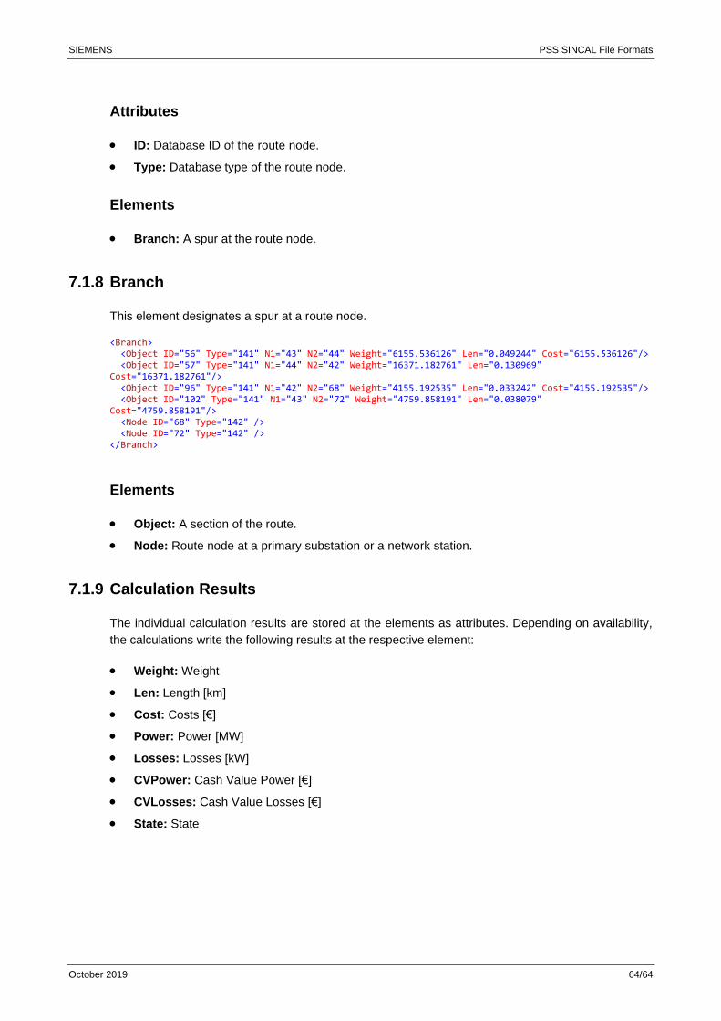
SIEMENS PSS SINCAL File Formats
October 2019 64/64
Attributes
• ID: Database ID of the route node.
• Type: Database type of the route node.
Elements
• Branch: A spur at the route node.
7.1.8 Branch
This element designates a spur at a route node.
<Branch> <Object ID="56" Type="141" N1="43" N2="44" Weight="6155.536126" Len="0.049244" Cost="6155.536126"/> <Object ID="57" Type="141" N1="44" N2="42" Weight="16371.182761" Len="0.130969" Cost="16371.182761"/> <Object ID="96" Type="141" N1="42" N2="68" Weight="4155.192535" Len="0.033242" Cost="4155.192535"/> <Object ID="102" Type="141" N1="43" N2="72" Weight="4759.858191" Len="0.038079" Cost="4759.858191"/> <Node ID="68" Type="142" /> <Node ID="72" Type="142" /> </Branch>
Elements
• Object: A section of the route.
• Node: Route node at a primary substation or a network station.
7.1.9 Calculation Results
The individual calculation results are stored at the elements as attributes. Depending on availability,
the calculations write the following results at the respective element:
• Weight: Weight
• Len: Length [km]
• Cost: Costs [€]
• Power: Power [MW]
• Losses: Losses [kW]
• CVPower: Cash Value Power [€]
• CVLosses: Cash Value Losses [€]
• State: State