Embed Size (px)
Citation preview
Annexure-03
PSLV Integration Facilities - PIF
REQUEST FOR PROPOSAL DOCUMENT
December-2017
SDSC SHAR INDIAN SPACE RESEARCH ORGANIZATION
2 | P a g e
Table of Contents
1. INTRODUCTION TO PSLV INTEGRATION FACILITIES (PIF) ................................................ 4
2. SCOPE OF WORK OF TECHNICAL SERVICE PROVIDER ....................................................... 5
3. INTEGRATION BUILDING: ................................................................................................ 6
3.1 CIVIL STRUCTURE: ................................................................................................................................ 7
3.2 EOT CRANE ......................................................................................................................................... 11
3.3 PLATFORMS ........................................................................................................................................ 16
3.4 DOORS ................................................................................................................................................ 19
3.5 SAFETY SYSTEMS: ............................................................................................................................... 22
3.6 FIRE FIGHTING SYSTEM: ..................................................................................................................... 24
3.7 ELEVATORS ......................................................................................................................................... 25
3.8 AIR CONDITIONING & COOL AIR SYSTEM.......................................................................................... 27
3.9 PNEUMATIC AND CHECKOUT SYSTEM .............................................................................................. 32
3.10 CCTV, INTERCOM, TIMING, COMMUNICATION AND TELECOM ....................................................... 32
4. SERVICE BUILDING ........................................................................................................ 32
4.1 CIVIL STRUCTURE ............................................................................................................................... 32
4.2 EOT CRANE ......................................................................................................................................... 35
4.3 DOORS ................................................................................................................................................ 40
5. MOBILE LAUNCH PEDESTAL (MLP) ................................................................................ 43
5.1 PURPOSE............................................................................................................................................. 43
5.2 DESCRIPTION ...................................................................................................................................... 43
5.3 FUNCTIONAL REQUIREMENTS/SPECIFICATIONS ............................................................................... 43
6. BOGIE SYSTEM .............................................................................................................. 44
6.1 STRUCTURAL CONFIGURATION ......................................................................................................... 45
6.2 HYDRAULIC JACKING SYSTEM ............................................................................................................ 46
6.3 POWER PACK FOR JACK OPERATION ................................................................................................. 46
6.4 ELECTRICAL SYSTEMS ......................................................................................................................... 47
7. SELF PROPELLING UNIT (SPU) ........................................................................................ 47
7.1 SCOPE: ................................................................................................................................................ 47
7.2 PURPOSE: ........................................................................................................................................... 47
7.3 DESCRIPTION: ..................................................................................................................................... 47
7.4 FUNCTIONAL REQUIREMENTS/ SPECIFICATIONS .............................................................................. 47
7.5 SALIENT FEATURES REQUIRED IN THE SPU ....................................................................................... 48
8. RAIL TRACK SYSTEM...................................................................................................... 48
8.1 CIVIL STRUCTURE OF SINGLE RAIL TRACK ......................................................................................... 49
8.2 RAIL TRACK SUB-SYSTEMS ................................................................................................................. 50
8.3 ANCHORING SYSTEM ......................................................................................................................... 50

3 | P a g e
9. ELECTRICAL SYSTEMS .................................................................................................... 51
10. INTERNAL ROADS ......................................................................................................... 59
11. MODIFICATIONS AT FLP ................................................................................................ 59
11.1 DISMANTLING OF LAUNCH PEDESTAL AND CONVERSION TO MLP ANCHORING SYSTEM .............. 59
11.2 RAIL TRACK SYSTEM ON JDD ............................................................................................................. 60
11.3 UT MODIFICATIONS ........................................................................................................................... 60
12. AUXILIARY BUILDINGS .................................................................................................. 60
Page 4
1. INTRODUCTION TO PSLV INTEGRATION FACILITIES (PIF)
PSLV Integration Facilities (PIF) is an augmentation project to First Launch Pad
(FLP) to increase launch frequency. Present FLP configuration is of Integration On
Pad (IOP) concept which consists of:
1.1 MOBILE SERVICE TOWER (MST): It is a steel structure of 22(L)X18(W)X76(H) m
and encloses Launch Pedestal(LP) and Umbilical Tower(UT). It provides access
requirements for vehicle integration, checkout and leak checks; clean room for
spacecraft assembly and self-contained Traction system for movement from LP
end to parking end, facilitating the launch. It protects vehicle under adverse
weather conditions.
1.2 LAUNCH PEDESTAL (LP): It is of fixed type, of size 10X10X7.267(H) m. It provides
necessary support for launch vehicle integration and launch. Propellant and gas
servicing lines are routed inside the launch pedestal and terminated at
appropriate locations.
1.3 UMBILICAL TOWER(UT): It is 51m tall structure. It provides enclosure for
propellant, gas & cool airlines and checkout cables. It also provides support for
all vehicle umbilical and necessary pull out anchoring points.
1.4 JET DEFLECTOR DUCT(JDD): It lined with refractory layer to guide the exhaust
gases of launch vehicle. Two no’s of track beams are provided over JDD for
enabling the movement of MST.
To increase launch frequency from FLP, the PIF project is proposed which consists
of mainly,
� NEW FACILITIES TO BE REALIZED: The following are the augmentation works,
which forms the part of PIF Project:
Sl.No System Description
1. Integration Building To facilitate the integration of vehicle
2. Service Building To facilitate the MLP refurbishment and
Core Base Shroud trial suiting activities
3. Mobile Launch Pedestal To provide base for vehicle integration and
launching
4. Bogie To support MLP along with vehicle for
transportation to FLP from PIF integration
building and has jacks for lifting/lowering of
MLP for anchoring
5. Self-Propelled Unit (SPU) To haul MLP (with vehicle) along with bogie
from PIF integration building to FLP and vice
versa. It shall also carry MLP (without
vehicle) from track to service Building for a
distance of 250m.
6. Rail track To haul bogie with span of 7.5m. It connects
Page 5
PIF integration building to FLP-MST.
7. Associated systems Air Conditioning, electrical and part of safety
systems etc.
The overall layout of PIF complex along with FLP is shown in the figure-1.
� MODIFICATIONS IN FLP:
1. Converting fixed Launch Pedestal to Mobile Launch Pedestal, laying new
track beams over JDD for the movement of MLP.
2. Establishing anchoring arrangements for MLP.
3. It also involves modifications in the Umbilical Tower, which is not in the
scope of consultancy.
OPERATIONAL PHILOSOPHY OF PIF COMPLEX:
• CBS trial positioning on MLP will be carried out at service building.
• SPU will carry MLP and position it in integration building.
• PSLV integration activities upto PS4 will be carried out in integration building.
• Comprehensive leak checks and checkout activities will be carried in the same
building.
• Protection hood will be positioned over the PS4 stage.
• Vehicle will be moved using bogie and SPU, over the 1.5km curved track to FLP.
• Anchoring of MLP will be carried out at FLP and bogie along with SPU will be
withdrawn from FLP.
• Satellite assembly and heat shield closure activities will be carried out as per
existing procedures until launch.
• After launch, MLP will be moved using bogie and SPU to external anchor point
infront of PIF Integration building.
• Bogie will be withdrawn from MLP and MLP will be moved to service building.
• TPS refurbishment and propellant gas line servicing of MLP will be carried out
at service building.
2. SCOPE OF WORK OF TECHNICAL SERVICE PROVIDER
2.1 DESIGN SERVICES FOR PSLV INTEGRATION FACILITIES:
The following design stages are considered:
S.No. Description of activities in Phase Phase Number
1 Conceptual and Preliminary design Phase - I
2 Detail design / critical design/ engineering/ fabrication
drawing preparation
Phase – II
3 Preparation of tender specification documents based on
critical design / preliminary design as per scope mentioned
below
Phase – III
4 Certification of design changes during fabrication/
construction
Phase – IV
Category-A: Phase-I to Phase-IV
Category-B: Phase-I (PDR) and generation of Tender Specification documents based
on PDR
Page 6
Category-C: Interfaces to be incorporated in Fabrication Drawings/Floor layouts
based on Department Inputs (after PDR) meeting all systems
requirements/loads.
Facility/ Systems Category-A Category-B Category-C
Integration Bldg. • Civil, Electrical, Air
Conditioning & cool
air systems
• Platforms, Drives,
Sliding Doors
EOT Cranes, Elevators,
Safety Systems
Fire Fighting,
Pneumatic,
Checkout, CCTV
and allied systems
Service Bldg. Civil, Electrical and Sliding
doors
EOT Crane, Safety
Systems
Pneumatic
systems
Mechanical Systems Bogie, Mobile Launch
Pedestal
-- For SPU, Tractive
effort required
shall be computed
and required
interfaces on MLP
shall be provided
Modifications at FLP • Track Beams on JDD
• MLP anchoring at
FLP.
-- --
Auxiliary Bldgs.
• Checkout &
Gas Systems
Building
• A/C systems
Building
• Technical
Service
Building.
Civil, Electrical Safety Systems --
Rail Track system Civil structure, Rail track
subsystems and
anchoring system
-- --
Roads Roads between service
building and integration
building.
Paved area around
Integration building.
-- --
3. INTEGRATION BUILDING: It is intended for receiving the segments/ stages/ sub-systems of the launch
vehicle, tilting and handling them inside the facility wherever required, integrating
them on a Mobile Launch Pedestal (MLP), performing checkout operations and leak
checks (stage level & full vehicle). Attaching Bogie & Self Propelled Vehicle (SPU) to
MLP, vehicle will be rolled up to Mobile Service Tower (MST)/FLP for launch. This facility
is sized to carry out integration of PSLV.
Page 7
PIF Integration Building is fully air-conditioned RCC structure of 35m(L) X30m(W)
X60m(H), which provides a comfortable and controlled environment for integration of
the launch vehicle. The building is equipped with the following provisions to carryout
vehicle assembly operations:
• 125/25t EOT crane for handling the vehicle stages/ hardware
• Ten sets of Foldable Platforms (FPs) to provide approach to vehicle at different
elevations
• Six sets of mechanized Horizontally Sliding Doors (HSDs) on the front side to
give way for the vehicle to move out and one set of HSD on rear side to receive
MLP
• Rail track with one set of ground anchor for positioning and anchoring the MLP
(inside integration building) with fully integrated vehicle.
• Two nos. of elevators for goods cum passenger travel.
Further, Integration building needs to have interfaces for the following sub-
systems which become part of the building:
• Air conditioning and Vehicle cool air systems
• Checkout, instrumentation and control system.
• Helium, Nitrogen and compressed air supply systems
• Provision for one more set of ground anchors inside PIF integration building.
• Electrical power supply, distribution and aviation lamps
• Earthing and Lightning Protection System
• CCTV and communication network
• Firefighting /safety systems
• Internal and external staircases etc.
The general arrangement of Integration Building is shown in FIGURE-2, 3 & 4
3.1 CIVIL STRUCTURE:
3.1.1 PURPOSE
To serve as weather proof shelter for vehicle assembly by having external door
and platforms inside the building. It also caters crane and its handling loads.
3.1.2 DESCRIPTION
� PIF is a RCC framed structure of clear external width 30.0m, length 35.0m and
height 60m at spring level.
� It shall be provided with necessary embedment for supporting EOT crane, fixed
platforms/catwalks/doors/fire fighting system pipes/cable trenches/ A/C ducts
etc.
� Whole building being the load bearing framed RCC structure, all sides shall be
closed with RCC walls other than the door opening area.
� It shall have 15 nos’ of floors of levels 5.5 m, 8.0 m, 12.2 m, 15.5m, 18.8 m, 22.1
m, 25.1 m, 29.0 m, 33.0 m, 37.0 m, 41.2 m, 45.0m,49.0 m, 53.0m and 56.5 m.
� Cat walks shall be provided on front& rear sides at all floor levels. Embedment
shall be provided for fixing doors and their mechanisms and also for the
Page 8
requirements of elevator.
� Stair cases shall be provided for access to various levels. Inside building, rails shall
be laid in flush with floor for MLP movement from front side of Integration
building.
� All the columns/beams/projections/window panels inside building shall be
designed in such a way to avoid roosting of birds.
� Anchors shall be provided on floor on either side of the track for anchoring the
MLP during vehicle integration.
� The floor inside integration building shall be designed for the MLP movement over
SPU.
3.1.3 FUNCTIONAL SPECIFICATIONS:
� It shall be a weatherproof shelter and air-conditioned enclosure for Launch vehicle
integration and checkout activities.
� It shall accommodate MLP, over which the vehicle will be integrated.
� It shall provide interfaces for Fixed Platforms (FPs) & Horizontal Sliding Doors (HSDs)
and their drive mechanisms.
� Ground floor shall be designed to carry the loads of trailers with subsystem loads,
MLP+SPU loads, and SPU carrying MLP over it during transportation to integration
building from service building.
� Foundations shall be provided for MLP rail track suitable for 125t wheel load and
for four ground anchors of 200t load each or the combination of the following;
whichever is higher
i. MLP weight
ii. Bogie weight
iii. Vehicle weight
� MLP rail track center shall be 3m offset from Building center line as indicated in
figure-2 & 4
� Ground anchors shall take care of repositioning accuracy based on rail and wheel
clearances.
� Two nos. of 40t capacity hooks shall be provided from the roof for supporting the
chain pulley block / winch pulley for crane erection and maintenance works.
� The building shall be provided with lifts, staircase and cat walks to reach various
floor levels.
� The building shall have provisions to house AC ducts, cool air ducts, pipe lines for
Helium, Nitrogen & Compressed air service, trenches/ ducts for power, checkout
& communication cables.
� The space available in between portal frames will be used for accommodating
lifts, stair cases, A/C plant equipment, cool air system, drive mechanisms and
diversion pulleys of platforms &doors, duct for service gas lines, checkout, power
& control cables and to position integration platforms & equipment.
� For the elevators, embedment shall be provided at all floor levels to support lift
Page 9
guide rails and for lift machine equipment inside machine room.
� Pits of suitable size shall be provided for both elevators of 2000kg capacity at
0.0m level as per mandatory standards. No water should seep into the pits.
Bottom of the pit shall be provided with embedments for supporting the lift end
buffers.
� The embedment/provisions are required to be provided for cat walks, platforms
&drive mechanisms, Doors & drive mechanisms, cranes, elevator, A/C, satellite
cooling system, ducts for service pipe lines, Checkout and power cable trays, light
fittings, lightning arrester masts, maintenance cradle etc.
� Embedments shall be provided on columns to support fixed foldable platforms,
on either side of vehicle center line.
� Handrails shall be provided on all catwalks and around all floor cutouts and on
rooftop for personnel safety. Handrails shall be of two-tier construction with a
toe guard of 100 mm. The handrail height shall be1.2 m nominal.
� At the location of entry to platforms from catwalks, manually operated sliding
hand rails with locking provision shall be provided to the extent of 1.5 m on either
side of vehicle center line.
� The building shall be provided with necessary glass windows for getting sun light.
Window panels shall be capable of withstanding cyclonic wind and they should be
leak proof to prevent entry of rain water.
� The building shall be provided with two staircases inside the building. Staircase
should be adjacent to elevator. Staircase should reach up to the top of the
building. Outside staircases shall be planned for emergency escape and to access
A/C plant rooms/Checkout rooms, depending on feasibility.
� Provisions shall be made in the building to install multiple entry escape chutes.
� Front and rear walls of the building shall have smooth surface in the areas of door
movement to have waterproof and to avoid rodent entry, sliding joint between
walls and doors when the doors are closed.
� There shall be no trough or any projections from the building for water collection.
No water shall get collected on roof of building. There shall be suitable drainage
arrangement for the disposal of rainwater from the roof and to avoid rain water
spillage over wall from roof. Rain water shall be drained properly to ground
through proper mechanism. No water shall enter on to the floor of the building,
when the doors are closed.
� Hoods shall be provided over horizontal sliding doors to prevent entry of water
between door & wall and other interfaces even during cyclone.
� Embedment shall be required for LT girder of 125/25t crane (crane LT rail top is
54.0m). Span of the crane is 20.0 m.
� MLP track and anchor foundations inside the building shall be provided as part of
building ground floor.
� Drinking water with a cooler and toilet provision shall be made to meet the
requirements of at least 25 persons at one location with proper drainage
for waste water in ground level on either side of the Service building.
Page 10
� Floor cut-outs shall be provided throughout the height for two lift wells and for
cables and gas lines routing
� Loads to be considered for civil structural design shall be:
a. Wind load:
� The structures are to be designed for wind speeds as per IS 875 Part 3: 2015 code.
� Basic Wind Speed to be considered, Vb = 65 m/s at 10m elevation [Includes Post
cyclonic importance factor k4 i.e. 50*1.3]
� Probability factor, k1 = 1.09
� Terrain & Height factor, k2 = for terrain category 2
� Topography factor, k3 = 1.0
� Vz = Vb * k1 * k2 * k3
� Wind pressure at height z, pz = 0.6 (Vz)2
� Design wind pressure, pd = Kd * Ka * Kc * pz
� For calculation of design pressures, the wind directionality factor, Kd = 1.0 and
area averaging factor, Ka = 1.0 and combination factor, Kc = 1.0 are to be
considered.
� The above values are for Peak gust method (3 sec Gust).
� The designer or consultant has to check the possibility of dynamic effects due to
wind on the structures and should evaluate the Dynamic loads (Gust Factor
Method) as per IS 875 Part 3: 2015.
� The greater of the two methods is to be adopted for the design.
� Design shall satisfy the deflection criteria of H/500 for cyclonic winds and 0.004XH
for Earth quake loads as per new codal provisions.
b. Live loads due to personnel & equipment
� Loads due to crane of 125/25tcapacity (self-weight + payload weight of
125t + dynamic loads due to crane starting and stopping with loads acting at 60.0m
level) and loads due to 40t capacity hook provided in the roof of building for crane
erection and maintenance.
� Axial, lateral, vertical loads and moments of the platforms (deadweight of
platform+ live load of 250 kg/m2 UDL & 1500 kg tip load of the platform) + and 2t
equipment weight spread over an area of 2mx1m in addition to dead loads
computed based on the unit weight of materials as per IS: 1911.These loads shall
be considered for design of other sub-systems also.
c. Loads due to the doors and associated drive mechanisms (dead weight+ wind
loads)
d. Live load on catwalks and floors except ground floor is 250 kg/m2.
e. Loads due to Foldable Platform drive mechanisms, door mechanisms and
associated systems, AC equipment, elevators and electrical equipment shall be
considered for the design of the floors.
� Floor load on ground floor shall be as per CLASS-AA and also considering the load
due to MLP & SPU whichever is higher
� Wheel load of 125t on single rail track with centre-to-centre distance of 7500
mm shall be considered.
� On the roof a live load of 150 kg/m2, loads due to masts of the lightening protection
Page 11
system, maintenance cradle and two nos. of 40t capacity hooks shall be
considered. Roof is to be of steel structure with trusses over which RCC slab of
sufficient thickness has to be laid.
� Two RCC water tanks of 50 m3 each capacity shall be provided on either side of
the building at 53 m elevation. It shall be on independent pedestal without direct
interfacing on flooring.
� The proposed configuration of the building structure is shown in figure-2,3,4.
3.2 EOT CRANE
3.2.1 PURPOSE
To receive the segments/ stages/ sub-systems of the launch vehicle, tilting them
inside the facility wherever required, handling and integrating them on Mobile Launch
Pedestal (MLP).
3.2.2 DESCRIPTION
A 125/25 t capacity EOT crane with increased safety features is proposed in
Integration Building with gantry level at an elevation of minimum 54.0 m to meet the
handling requirements. The crane shall have a LT provis ion of 25.0m (minimum) and
CT provis ion of 15.0m (min imum) to meet the integrat ion requirements. General
arrangement shown in figure-11 & 12
3.2.3 FUNCTIONAL REQUIREMENT/ SPECIFICATIONS
• Crane has to safely handle the Sub-systems of the launch vehicle received at ground
in vertical or horizontal condition.
• Dual drive control system (VVVF Drive control) shall be provided for all the motions.
In case of failure of one VVVF drive system, the crane should be operable without any
problem with other drive.
• Crane hook shall have a reach to the closet point possible from all side walls/ doors
to handle various hardware items.
• The brakes shall be effective and accurate to stop the crane within a very short
distance and in a safe and smooth manner.
• The crane shall have precise control/movement to align the parts for integration with
variable speeds (VVVF Drive control).
• Building crane shall be operated from pendant control at 13levels at different
elevations. The platforms are located at elevations of 0.0 m, 5.5m, 8.0m, 12.2m,
15.5m, 18.8m, 22.1m, 25.1m, 29.0m, 33.0m, 37.0m, 41.2m & 53.0m.
• Dual drive system with single chain capable of hoisting, shall be considered for hoist
motion.
Page 12
The EOT crane shall have the following technical parameters
Type Double girder indoor type
Duty class Class2as per IS 807-1067/IS
3177-1977
No. of trolleys (Crab) One
Operating Levels
13 working levels. Provision shall be made for operating through plugintype intrinsically safe pendantsfrom both sides at each level
Safe working load Main hoist 125t
Auxiliary hoist 25t
Highest position of
hooks above
top of floor level
Main hoist 54.0 m
Auxiliary hoist 54.0 m
Span 20 m
Gap between the centers of crane LT rail and
nearest side obstruction 0.5 m
Height of the crane from the hook at maximum lift
position to the top most point in the crane (lesser
height is preferred)
6.0m (max)
Spring level of Integration Building 60.0 m
Level of gantry girder rail for LT 54.0 m
Operational
speeds
Hoisting speed
max (Main &
auxiliary)
With load 3 m / min
Without load (empty
hook) 6 m / min
Creep speed 0.3 m / min
Long travel
speed
With min load 3 m / min
Creep speed 0.3 m / min
Cross travel
speed
With min load 3 m / min
Creep speed 0.3 m / min
Power
supply
Voltage 415 V ±10%
Phase 3
Frequency 50 Hz +/- 5%
Combined variation voltage and
frequency
10%max.
(Absolute sum)
Page 13
• Head room of minimum 2m must be available above the 125/25t EOT crane for
maintenance works.
• The crane shall be provided with single rope system which is hot dip galvanized with
independent wire rope core and of non- rotating type.
• Electrical contactors shall be suitable for 300starts/hr.
• Intrinsically safe junction boxes and plug sockets shall be provided on either sides
of the platform level. Two numbers of portable trolley type, intrinsically safe, multi-
pin plug-in type light weight pendants shall be provided along with a lead cable of
30m length to plug the same at any of the plug sockets at various platform levels.
Light weight pendants with interlock arrangement shall be provided.
• Each hook block shall have suitable bearings and shall rotate freely. Ramshorn hook
for 125t and C hook for 25t capacity and shall also have safety latches.
3.2.4 ELECTRICAL:
• Motors shall be with increased safety features. Main hoist motor may be of crane
duty squirrel cage/slip ring type, all other motors shall be squirrel cage crane duty
type.
• The motor insulation shall be class F and also compatible for all drives tropicalized
by coating with non-hygroscopic coatings, suitable for operation in sea shore area.
• Main control panel shall be provided in electrical panel room of building with
sufficient working space all around with weather proof enclosures. Cabling shall be
fire retardant, low smoke, armored and tinned copper cable.
• Junction boxes provided on the crane & near the crane shall be with increased safety
features.
• In case of multiple drives either for CT or LT speed synchronization shall be provided.
In such cases individual drive shaft shall be designed to take the full load.
3.2.5 BRAKES:
• The brakes shall be operated using electro-hydraulic thrusters. Hoist motion shall be
provided with redundant brake. All thruster brakes shall be highly reliable.
3.2.6 DESIGN:
• Crane structure shall be designed in accordance with IS: 807 with its latest edition /
revision.
• Mechanical, electrical, design, inspection and testing requirements shall be in
accordance with latest IS: 3177.
• Intrinsically safe apparatus and circuits, wherever specified, shall belong to category
I Band shall be as per IS: 5780. The temperature classification shall be T4 of IS: 8239.
• Crane shall also be used to tilt the sub-systems received in horizontal condition to
vertical. During tilting, LT motion of the crane shall be used along with the tilting
fixtures. This is to be taken to account while configuring the orientation of rope
drums.
Page 14
3.2.7 DESIGN AND STRUCTURAL CONSTRUCTION GENERAL
• Design of components shall be based on the relevant standards.
• Wherever applicable the crane shall be rigid in construction and all movements shall
be smooth and non-jerky.
• Design shall provide for easy maintenance of all parts particularly the wheel bearings
on end-trucks. Necessary safe and sufficient working space shall be provided all
around the sub systems for easy maintenance.
• For load carrying members the component plates, bars, angles and other rolled
sections, the minimum thickness shall be 4.9mm (6 SWG). For unsealed tubes, the
minimum thickness shall be 8 mm. The chequered plates for platforms shall be of
minimum 6 mm thick.
• Unless otherwise specified, only welded joints shall be used. Where welding is not
practicable, turned and fitted bolts shall be used. Connection between carriages and
main girders shall be by means of machined bolts fitted in reamed holes. Minimum
number of turned and fitted bolts in connection shall not be less than two.
3.2.8 RUNWAY / TROLLEY RAILS
• The rail section shall be as per IS: 3443 BRIDGE GIRDER
• The crane shall be of double girder type.
• The bridge girder shall be of box section. The exterior surface shall be smooth and
free from projections to minimize dust collection on it.
• In bridge girder strength calculations, the trolley rails and chequered plates shall not
be considered as load carrying members.
3.2.9 RULING DIMENSIONS & RATIO
• For compression members, the slenderness ratio shall not exceed 120. In case of
other load carrying members and subsidiary members slenderness ratio shall not
exceed 180.
• For girders, the following values of maximum span to depth ratio shall be governing:
Plate girders : Span/Depth= 18
Lattice girders : Span/Depth=12
DEFLECTIONS AND CAMBER
• The total maximum vertical deflection of the girders for the live load plus trolley and
not including impact or dead load of the girder shall not exceed limit of span /1000.
• The girders shall be cambered by an amount equal to the maximum deflection due
to dead load plus one half the live load and trolley.
LIFTING HOOK BLOCK ASSEMBLY
• The lifting hook block assembly shall be point hook / Ramshorn with adequate
capacity and shall be of forged steel construction. Each hook shall be supported on
ball or roller thrust bearing and shall rotate freely on its bearing by manual
operation. The lifting hook shall have a safety latch.
Page 15
BRAKES
• Electro hydraulic thruster brakes of suitable rating to stop the crane within a very
short distance and in a safe and smooth manner. They should be equally effective in
both directions.
• Double-shoe type service brake shall be provided for each motion of the crane.
These brakes shall be directly applied automatically to the motor shaft when power
supply to the drive motor is cut-off or fails. The brakes shall be equally effective in
both directions of rotation. Two brakes each rated 2 times of motor rated torque/
suitable capacity shall be provided for hoist motions of both hooks.
• Service brake for hoist motions shall be adequately sized to arrest and hold at rest
any load up to and including test load at any position of the lift. For hoist motion,
redundant brake is required to be provided and the capacity shall be such that each
brake can satisfactorily meet the requirements of the braking.
• Brake drum shall be positively locked in position so as not to prevent lateral
movement by means or retainer plated or any other means.
• Thrusters shall have reserve of at least 30% stroke length available for necessary
adjustment as well as provision for adjustment of time for upward and down ward
travels of the piston.
• All brakes shall have smooth braking capability to decelerate in safe manner to avoid
any derailment even when applied at maximum speed. The braking action of hoist
motion shall be such that there shall not be any jerks for the objects being lifted at
main speed.
EMERGENCY MODE OPERATION
• An emergency stop pushbutton shall be provided in the intrinsically safe pendent.
On operation of this push-button all electro-hydraulic brakes shall be applied
immediately to all motions and power shall be cut off to electrical motors.
• Each hoist motion shall be provided with self-contained, sturdy, automatic braking
system to prevent over speeding of the hoist. These over speed brakes may be
mechanical load brake type, AC regenerative or DC dynamic type as per standard of
the manufacturer.
MOTORS
• All crane motors shall be totally enclosed, fan cooled type.
• The increased safety motors shall be designed for crane duty requirement of
frequent starting, reversing and braking. The motor pull out torque shall not be less
than 2.20 times rated torque.
• Motor shall suit the duty Class S4, cyclic duration factor 40% and number of starts
per hour 300.
• All increased safety motor with rating 30kw and above shall be provided with space
heater, sized to maintain motor internal temperature above dew point when the
motor is idle.
• In the hoist motion, where empty hook drive is specified, if the main motor is in the
drive link during the operation of the empty hook drive, the main motor shall have
the capacity to rotate at higher speed of empty hook drive motor without any
damage to rotor windings of main motor with sufficient margins.
Page 16
CONTROLLERS AND CONTROL SWITCHES
• Fully magnetic control shall be provided for hoist motion, long travel and cross travel
motions, complete with contactors, time lag relays, resistors and other accessories
to meet the control requirements given in specification.
• Flame retardant control cables from the crane shall be brought out by cable drag
arrangement to a junction box located near the LT rails. The control cables from this
junction box shall be connected to suitable intrinsically safe junction boxes with
multi pin plug sockets and hinged covers to be provided at two sides of specified
floor levels.
• Portable trolley mounted intrinsically safe, multi-pin plug -in type pendants shall be
provided along with a Flame retardant lead cables of 30m length to plug the same
at any of the plug sockets at various floor levels. Where more than one pendent is
provided for a crane, interlock arrangement shall be provided, so that at any given
instant crane can be operated using only one pendent.
• Suitable locking facility shall be provided between the socket and plug such that at
no instance the plug can come out of the socket inadvertently. All apparatus and
circuits contained inside the pendant push button station, junction boxes, plug
sockets etc., shall be intrinsically safe, as per IS:5780. The degree of protection
offered by the enclosure to the pendant push button station shall be group IIB as
per IS: 2147.
• Push button shall be spring return type, with 2NO +2 NC contacts rated 10A, 110V
AC. Indicating lamps shall be of low watt consumption lamp and provided with series
resistor.
3.3 PLATFORMS
3.3.1 PURPOSE
To provide access for integration of launch vehicle at required levels between
8.0m and 41.2m elevation and to provide a space for integration. By folding the
platform, it provides space for movement of integrated launch vehicle.
3.3.2 DESCRIPTION
For carrying out the vehicle integration operations, personnel are required to
reach the vehicle at various levels in integration building throughout the height of
vehicle and approaches are required close to the vehicle. To meet these operational
requirements, 10 nos of platforms of size 10m x 10m are envisaged. These 10 no’s of
platforms shall serve all the operational platform levels from 8.0 to 41.2 m level.
Electro mechanical systems like winch mechanism shall be planned for folding
operation of the platform.
3.3.3 FUNCTIONAL REQUIREMENTS/ SPECIFICATIONS
• Each half of platform size is 10 m (along the building length) X 5 m (across the
building width).
• The platform shall be of 2 modes of folding type with suitable hinges. The
platform shall be configured into two segments of 1.9m and 3.1 m length,
Page 17
which can be folded as a single unit of 5m length or of 3.1m length, in which
case 1.9m length will be fixed in horizontal condition.
• Suitable hinge lock system shall be provided depending on the mode of
operation with either 3.1 m segment or both segments together (5m).
• The first mode of folding is 3.1m length folding shall provide a clear gap of
minimum 5.7m between 2 folded platforms with a folding angle of maximum
87 degrees.
• The second mode of folding is 5m length folding shall provide a clear gap of
minimum 8m between 2 folded platforms with a folding angle of maximum 80
degrees.
• The both modes of folding operation shall be carried out with single drive
mechanism.
• Platforms shall be configured for PSLV. Platforms shall have cut-outs suitable
to external configuration of launch vehicle with a possibility to cover/ close
the cut-outs meant for strap-ons depending on the integration requirements.
• The platform projections between strap-ons shall be slidable into the platform
before folding operation to avoid interference with the vehicle.
• Under actual operating loads, the platforms shall be sturdy and shall operate
smoothly.
• It shall be operatable from nearby fixed platform. Flame proof push button
switch shall be provided for operation near the mechanism. Operation control
for all the platforms shall be by means of local control panels located on the
platform.
• The platforms shall be designed for live load of 250 kg/m2 and a tip load of
1500 kg distributed on the edge of platform and 2t equipment weight spread
over an area of 2mx1m. These loads shall be considered for design of other
sub-systems also.
• Flame proof platform load monitoring system along with display, over load
tripping, adjustment and calibration provision shall be provided along with
local operating panel.
• Platform tip structural deflection shall be limited to L/325 mm where L is the
cantilever length of the platform. However, the platform deflection at the tip
shall be limited to maximum of 10mm.
• No oil shall drip from any part of the system. However, suitable oil drip tray
shall be provided for mechanisms.
• Effective toe guards shall be provided for all the platforms and guards shall be
provided for all rotating parts.
• Handrails of 1.2m height shall be provided on the platforms. Hand rails shall
not interfere with the vehicle or civil frame, when the platform is in folded
condition. Handrails shall be provided around platform with required openings
for entry from fixed portion. All entry openings shall be provided with sliding
Page 18
handrails.
• All electrical systems like motor, thruster brakes, over load sensing system,
limit switches, starters, etc. are all of flame proof type suitable for Class-IIB
application.
• The platform shall have provision to operate manually in case of failure of
electrical power.
• The drive motors shall be suitable for duty class S4, cyclic duration factor 40%
and number of starts/hour 150. Overload tripping provisions for electric motor
shall be provided at suitable location.
• The platforms shall be designed to operate both the halves independently.
• Suitable locking arrangement shall be provided for the platform when in
open(folded) position.
• Platforms shall have safety belts at its ends to take care of accidental wire
rope failures when in unfolded condition.
• Flameproof end limit switches with dual internal contact are to be
incorporated for operation of platform.
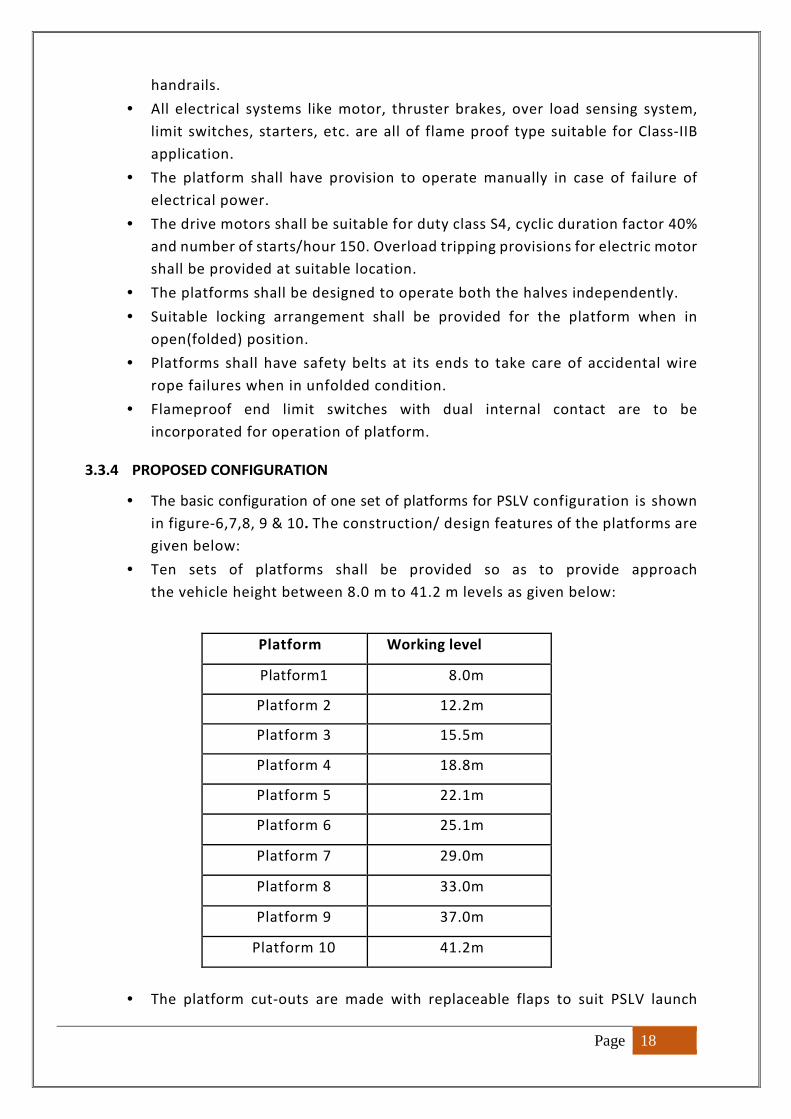
3.3.4 PROPOSED CONFIGURATION
• The basic configuration of one set of platforms for PSLV configuration is shown
in figure-6,7,8, 9 & 10. The construction/ design features of the platforms are
given below:
• Ten sets of platforms shall be provided so as to provide approach
the vehicle height between 8.0 m to 41.2 m levels as given below:
Platform Working level
Platform1 8.0m
Platform 2 12.2m
Platform 3 15.5m
Platform 4 18.8m
Platform 5 22.1m
Platform 6 25.1m
Platform 7 29.0m
Platform 8 33.0m
Platform 9 37.0m
Platform 10 41.2m
• The platform cut-outs are made with replaceable flaps to suit PSLV launch
Page 19
vehicle configuration. However, all other elements of platforms such as hinges,
pivots, drive systems, pulley systems, carriages, etc. shall be common for all
platforms.
• Platform locking provision shall be provided for both folding and unfolding
conditions for maintenance purpose.
3.3.5 PLATFORM DRIVE MECHANISM
• Suitable flameproof mechanism for folding and un folding the platform shall
be designed. Mechanism shall be simple, optimum and highly reliable.
• Each half of platform required one number of flameproof drive mechanism.
• Mechanism shall have flame proof limit switches for open and close position of
platform.
• Load monitoring and over load tripping provision shall be provided.
• Misalignment shall be avoided by suitable means/mechanisms between two
halves of the platform when in closed condition.
• The reduction gearbox considered for any winch mechanism shall be of non-
reversible type. The lubricant oil shall be of standard mineral oil based is
preferable.
• The drive wire ropes shall be of hot dip galvanized only. Each platform shall be
provided with additional stay rope/belt to carry full load.
3.3.6 GENERAL
• From fixed portions, approach provisions shall be made to reach the
platforms.
• The vertical mismatch at any point between the two halves of the platform
at any level not to exceed 5 mm in unfolded position without any live load.
3.4 DOORS
3.4.1 PURPOSE
To provide access to inside of Integration Building on front and rear sides
in such a way that launch vehicle is protected from the adverse weather
conditions from outside and to maintain a controlled environment inside the
building. Doors will be kept opened during vehicle to roll out to launch pad and
to receive the stages/segments for integration.
3.4.2 DESCRIPTION
For carrying out the integration activities in Integration Building, the sub-
systems are brought inside through the doors on front side. On the rear side
also door is provided enabling the movement of the MLP. The configuration and
design of the doors shall be such that even in case of cyclone, water or wind gust
should not enter the Integration Building.
Page 20
3.4.3 FUNCTIONAL REQUIREMENT/SPECIFICATIONS
• Doors shall provide clear opening for the movement of fully integrated launch
vehicle on MLP from the front side that is facing towards east. On the rear side,
clear opening shall be provided for the movement of the MLP and subsystems on
trailers.
• Doors shall withstand cyclonic winds as specified in the civil structure of
integration building. The mechanism shall be operable at 30 m/s wind velocity.
• Doors in closed condition need to protect the sub-systems and integrated
launch vehicle in Integration Building from cyclonic winds and rain. Suitable
separate cyclone lock arrangements shall be provided for doors to meet the cyclone
withstanding capability of integration building.
• Doors shall have perfect sealing at intra door interfaces as well as interface with
the Integration Building walls to prevent leakage of rain water even during
cyclone and to prevent rodents entry into Integration Building. In between
adjacent doors, tongue and groove interface maybe considered.
• The suitable protection hood shall be provided on the top most door to prevent
rain water entry through joints.
• The operation of each door shall be independent without any constraint.
• The Horizontally Sliding Doors shall be designed for the following load
conditions:
� Vertical loads: Dead load has to be computed based on the unit weight
of materials as per IS: 1911. Dead weight of door structure shall be
considered for the design of the associated sub-systems.
� Cyclonic wind loads as per IS 875 as described for building civil design
conditions shall be considered.
� Operating wind loads at wind velocity of 30 m/s for the drive system
� Wind load for door in open condition:30 m/s
� Acceleration and deceleration loads at the rate of 0.03 m/s2
� The following load combinations may be considered for designing of door
structure:
Case I: Dead load + Cyclonic wind load
Case II: Dead load + operational wind load + inertial loads
Speed of operation of doors: 2 m/min
� The drive motor shall be suitable for duty class S4, cyclic duration factor 40%
and number of starts/hour 150.
� Caving in of the doors shall be designed so that overall deflection of the
Integration Building structure shall not affect the operation of doors
� In closed condition, the matching edge of the two halves of each door shall
be within the following tolerances:
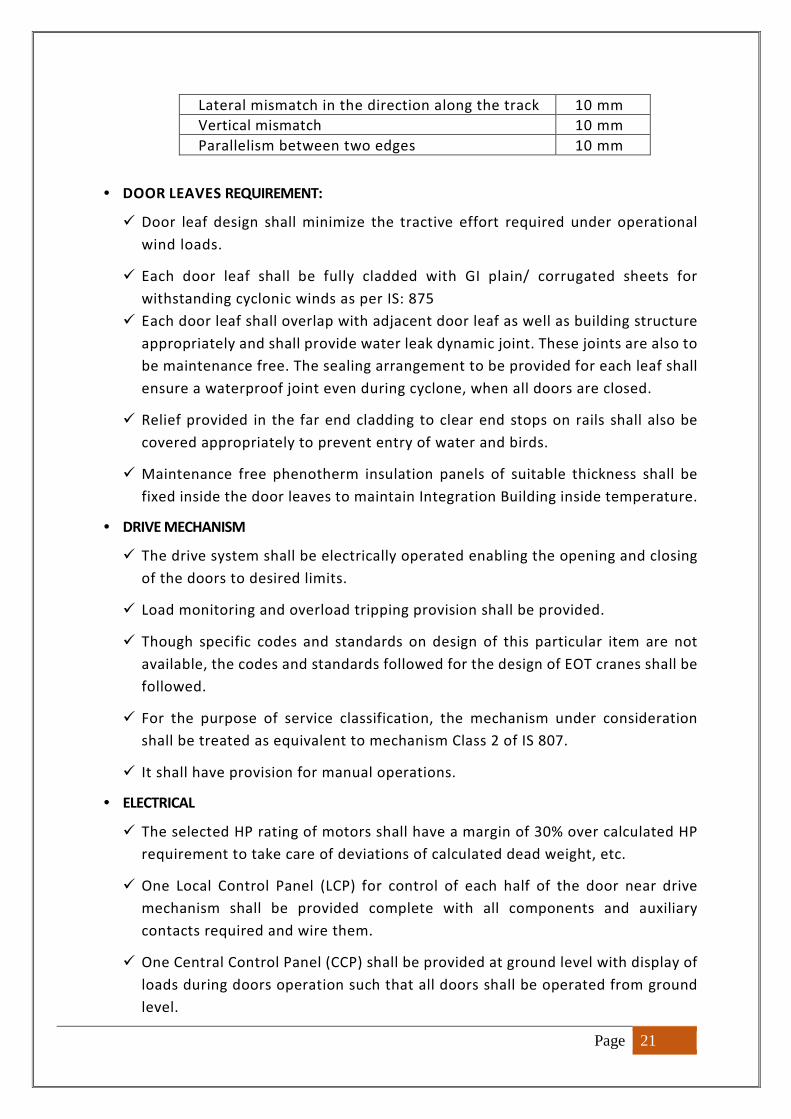
Page 21
Lateral mismatch in the direction along the track 10 mm
Vertical mismatch 10 mm
Parallelism between two edges 10 mm
• DOOR LEAVES REQUIREMENT:
� Door leaf design shall minimize the tractive effort required under operational
wind loads.
� Each door leaf shall be fully cladded with GI plain/ corrugated sheets for
withstanding cyclonic winds as per IS: 875
� Each door leaf shall overlap with adjacent door leaf as well as building structure
appropriately and shall provide water leak dynamic joint. These joints are also to
be maintenance free. The sealing arrangement to be provided for each leaf shall
ensure a waterproof joint even during cyclone, when all doors are closed.
� Relief provided in the far end cladding to clear end stops on rails shall also be
covered appropriately to prevent entry of water and birds.
� Maintenance free phenotherm insulation panels of suitable thickness shall be
fixed inside the door leaves to maintain Integration Building inside temperature.
• DRIVE MECHANISM
� The drive system shall be electrically operated enabling the opening and closing
of the doors to desired limits.
� Load monitoring and overload tripping provision shall be provided.
� Though specific codes and standards on design of this particular item are not
available, the codes and standards followed for the design of EOT cranes shall be
followed.
� For the purpose of service classification, the mechanism under consideration
shall be treated as equivalent to mechanism Class 2 of IS 807.
� It shall have provision for manual operations.
• ELECTRICAL
� The selected HP rating of motors shall have a margin of 30% over calculated HP
requirement to take care of deviations of calculated dead weight, etc.
� One Local Control Panel (LCP) for control of each half of the door near drive
mechanism shall be provided complete with all components and auxiliary
contacts required and wire them.
� One Central Control Panel (CCP) shall be provided at ground level with display of
loads during doors operation such that all doors shall be operated from ground
level.
Page 22
• SAFETY REQUIREMENTS
� The drive system for horizontally sliding doors shall be provided with travel limit
switches. The enclosure shall be of IP: 65 type.
� For all the sub-systems of the door, suitable approaches need to be provided
both for operation and maintenance.
� Effective guards shall be provided for all the rotating parts. All electrical
equipment should be properly guarded for protection against accidental contact.
� All electrical items shall be of flame proof construction.
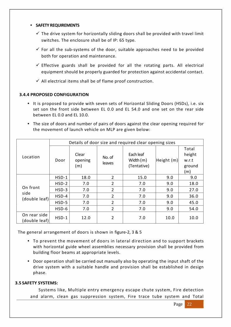
3.4.4 PROPOSED CONFIGURATION
• It is proposed to provide with seven sets of Horizontal Sliding Doors (HSDs), i.e. six
set son the front side between EL 0.0 and EL 54.0 and one set on the rear side
between EL 0.0 and EL 10.0.
• The size of doors and number of pairs of doors against the clear opening required for
the movement of launch vehicle on MLP are given below:
Location
Details of door size and required clear opening sizes
Door
Clear
opening
(m)
No. of
leaves
Each leaf
Width (m)
(Tentative)
Height (m)
Total
height
w.r.t
ground
(m)
On front
side
(double leaf)
HSD-1 18.0 2 15.0 9.0 9.0
HSD-2 7.0 2 7.0 9.0 18.0
HSD-3 7.0 2 7.0 9.0 27.0
HSD-4 7.0 2 7.0 9.0 36.0
HSD-5 7.0 2 7.0 9.0 45.0
HSD-6 7.0 2 7.0 9.0 54.0
On rear side
(double leaf) HSD-1 12.0 2 7.0 10.0 10.0
The general arrangement of doors is shown in figure-2, 3 & 5
• To prevent the movement of doors in lateral direction and to support brackets
with horizontal guide wheel assemblies necessary provision shall be provided from
building floor beams at appropriate levels.
• Door operation shall be carried out manually also by operating the input shaft of the
drive system with a suitable handle and provision shall be established in design
phase.
3.5 SAFETY SYSTEMS:
Systems like, Multiple entry emergency escape chute system, Fire detection
and alarm, clean gas suppression system, Fire trace tube system and Total
Page 23
flooding system, Portable Fire Extinguishers, Panic exit devices shall be part of
the building design.
3.5.1 MULTI ENTRY EMERGENCY ESCAPE CHUTE SYSTEM
The multi entry emergency escape chute is used as means of escaping
mechanism from the PIF integration building during emergencies. This system
shall cover entire height of the building as practicable as possible. This chute
shall be made of fire retardant material with multilayer. It shall be inside the
building isolated from integration bay in a cubicle. Staggering of escape chute
system as per requirement shall be made. It shall comply with requirement of
high rise explosive building confirming to National Building Code/NFPA/EU/ISO
or any other standards, statutory requirements and shall have required
approvals. The size and openings required, surrounding protective civil wall with
2 hours fire rated doors and interfacing provisions shall be covered in the civil
works to meet the requirements.
3.5.2 FIRE DETECTION AND ALARM (FDA) SYSTEM
Fire detection and alarm system shall be installed in the PIF building, Service
Building, Substation, AC Plant, PTR and pneumatic checkout rooms and in other
required rooms. FDA system shall be interfaced with fire suppression system and
AC plant through relay configuration for activation of fire protecting system and
tripping the AC system respectively to minimise the risk to the building in cross
zoning concept. The necessary conduit pipes, false ceiling/flooring openings,
response indicator provision and cable management systems shall be covered in
the civil/electrical contract to meet the requirements. The design, installation
and commissioning of the FDA system shall adhere to IS 2189/NFPA-72 or any
other relevant standard and shall have required approvals. The system shall have
provision to interface it with centralised monitoring system connected through
Ethernet.
3.5.3 FIRE TRACE TUBE SYSTEM
Wherever electrical panel rooms are planned in the PIF, suitable fire trace
tube system which automatically quenches the fire in the electrical panel, upon
detection of fire shall be provided. Suitable type and size shall be derived for
various panels planned in the buildings These systems shall meet the
EN/NFPA/BIS/PESO requirements or any other relevant standards and shall have
required approvals.
3.5.4 TOTAL FLOODING SYSTEM
Control rooms planned in auxiliary buildings near to PIF shall be covered with
approved total flooding system of suitable clean agent type. These systems shall
meet the NFPA/BIS/PESO requirements or any other relevant standards and shall
have required approvals. The necessary provision for keeping the
Page 24
extinguishment cylinders, pipe routing support embedment etc., shall be
covered under civil works to meet the requirement.
3.5.5 PORTABLE FIRE EXTINGUISHERS
Portable fire extinguishers as per IS 2190/ NFPA10 shall be installed in the
PIF building and other associated buildings. The requirement shall meet the
“High Hazard” category as per IS2190 / NFPA10 for PIF building. Other buildings
like service building, substation, checkout room, AC Plant and other rooms shall
also be covered with portable fire extinguishers as per IS 2190 / NFPA 10. These
systems shall meet the NFPA/BIS/PESO requirements or any other relevant
standards and shall have required approvals. The necessary provision for fixing
the extinguishers or providing in cubicles, support embedment etc., shall be
covered under civil works to meet the requirement.
3.5.6 PANIC EXIT DEVICES
All the exit doors shall be provided with easily openable outside panic exit
devices as per standard. These devices shall not have provision to openable from
outside. The necessary provision for fixing the panic exit devices, single leaf
doors on various emergency doors shall be covered under civil contract to meet
the requirement.
3.6 FIRE FIGHTING SYSTEM:
Civil and other requirements for water based firefighting systems:
• Department will provide the details of fire fighting system pipeline
configuration, its general lay out etc. Design verification for loads, providing
cutouts, embedments providing, routing of the lines inside the building is in
the scope of the technical service provider.
• The internal firefighting systems like internal fire hydrants and fire hose reels
shall have pipe support embedment and fixing arrangements for hose reels etc.,
through civil contract.
• Water resource for the same shall be from 2 Nos of 50 cu.m capacity water
tanks located suitably in either portal of Integration building.
• Pedestal for laying firefighting lines from the existing nearby firefighting
systems shall be provided.
• Any other provision requirements from civil/electrical for the realisation of
safety and firefighting system for the new proposal or augmentation shall also
be covered.
• Necessary provision for fixing gas check system in the required levels of
Integration building and service building shall be covered under civil works.

Page 25
3.7 ELEVATORS
3.7.1 PURPOSE
An elevator is meant to carry personnel and material to various floors of the
building.
3.7.2 DESCRIPTION
A goods cum passenger elevator of 2000kg capacity of reputed make to travel
from ground floor at 0.0 m to 53.0 m with stopping at all floors.
3.7.3 FUNCTIONAL REQUIREMENTS/ SPECIFICATIONS
• The Elevator shall operate from lower most portion of the vehicle assembly
Integration Building, i.e. EL 0.0 m to the top-level 53.0m (crane girder level).
• The elevation of various landing zones and the location of the elevator in
Integration Building is given in Figure-4, 5 & 6.
• The machine Room will be located at the top of the elevator shaft at an
elevation of 57.0m, complete drive, electrical and mechanical control
equipment, etc., shall be installed in the machine room. However, the non-
flame proof control panel shall be housed inside electrical panel room at lower
level.
• The elevator shall be designed, manufactured, tested and installed as per
recent IS 14665 Part 1 to 5.
The technical specifications are indicated as follows,
Operation Selective Collective Automatic Control
Speed 1.0 m/s
Car size (inside) To be decided based on 2000 kg elevator capacity
Inside clear height To be decided based on 2000 kg elevator capacity
Well size To be decided based on 2000 kg elevator capacity
No. of landings 15
Bottom most landing 0.0 m
Top most landing 53.0 m
Controller Latest configuration, Electronic type
• The elevator shall be designed for continuous 24x7 hours round the clock
operation.
• All electrical equipment inside Machine room shall be of non-flame proof with
increased safety and a non-flame proof control panel housed inside electrical
panel room at ground floor.
• The electrical works shall be designed for satisfactory operation for 415 V +/-
10%, 3 phase, 50 Hz +/- 5% solidly grounded system combined voltage and
frequency variation being 10% maximum (absolute sum)
• The motor insulation shall be class F or better tropicalized by coating with non-
hygroscopic coatings, suitable for operation in seashore area.
Page 26
• The maximum roof top deflection of the Integration building structure under
cyclonic winds, when the elevator is non-operational, is approx. 1/500 of the
total height of the structure. It shall be ensured that the elevator and guide
system are operational under such an event.
• Necessary safety devices shall be furnished to prevent the movement of the car
until the car door and all hoist way doors are closed properly.
• Necessary switches shall be furnished in the car to control the operation of the
doors.
• At every landing location and also inside the car, car position indicator shall be
provided.
• Emergency lighting, Telephone, Alarm, Emergency escape, Fan shall be
available inside the car.
• Trouble-free performance of the elevator incorporating the operational,
controlling and safety requirements, as specified, is to be guaranteed.
• At all intermediate levels up and down call buttons with indicators are to be
provided.
• The elevator shall be equipped with all standard safety systems such as Bell
and cranking in case of power failure, limit switches, indicators, over speed
safety governor for car and counter weight.
• Sufficient illumination shall be provided in the hoist way.
• The elevator shall be designed to lift a pay-load of 2000kg in addition to weight
of the car itself and other accessories.
• The number of wire ropes and size of wire rope shall be so chosen that highest
factor of safety is achieved as per standard.
• Every lift car shall be designed in a complete frame of steel which shall be
sufficiently rigid to withstand the operation of the safety gear without
permanent deformation to the car frame. Car side panels, roof and floor shall
be made with stainless steel with moon rock finish.
• At least four renewable guide shoes with renewable linings or set of roller
guides shall be provided two at the top and two at the bottom of the car frame.
• Necessary provisions shall be made for adequate ventilation of the car.
Ventilation openings shall be provided in the enclosure walls. A separate switch
has to be provided in the car for the fan.
• The elevator car shall be provided with one centre opening horizontally sliding
type doors. The doors operation shall be automatic. The door operation shall
have power operation for opening/closing.
• The car door and the hoist way door shall open automatically when the car
stops at a landing. The door operation shall be so designed that the doors can
be manually opened only at landings if the electric power fails.
• Over speed governor shall be provided for both car and counter weight.
• Suitable ARD shall be provided for taking care of power failure.
• The elevator input power supply shall be provided with phase reversal
protection
Page 27
• Elevator shall retain its position in the event of power supply failure.
• Elevator shall be provided with overload alarming system and floor
annunciator.
• Elevator shall be provided with fireman switch at ground level.
• The operating of the elevator i.e., method of actuating the control shall be
Selective Collective Automatic Operation' as per clause 2.4.2.3 of IS-1860-1968,
with and without attendant. All accessories required for the collective
operation' as outlined therein, namely selector and its driving type, floor bars
with electrical contacts etc., shall be furnished complete.
• The car shall furnish an operating panel containing pushbuttons, numbered to
the landing served; two-position key operated switch, marked to indicate
normal and VIP mode; and emergency call button connected to a bell to serve
as an emergency signal; push button or switches for fan and other push
buttons, switches as required.
• A signal indication shall be provided by the appropriate numeral (which shall
be floor level of the respective floor) being illuminated when the car is passing
the corresponding floor. The indication shall remain illuminate when the car is
stopped at a floor. Up and down direction jewel lights shall also be provided.
The car position indicators need to be provided at all landings also.
• A single "Up" or "Down" push button at terminal landings and separate ""Up"
and ""Down" push buttons at each intermediate landing including call register
lights for each push button shall be provided. These shall remain illuminated
until the call is answered.
• Car door shall be provided with infrared sensing system to retain the door in
open condition during the movement of personnel.
• Car door operating system shall be provided with pressure sensing switch in-
case as a redundancy to infrared sensing system.
• Suitable hand rails and buffers shall be provided inside the car.
• The terminal buffers shall be furnished for stopping the car and the
counterweight at the extreme ends of travel.
• Terminal limit switches for normal operation shall be provided to slow-down
and stop the car automatically at terminal landings and final limit switches shall
be furnished to automatically cut off the power and apply the brake, when the
car reaches the terminal landings.
3.8 AIR CONDITIONING & COOL AIR SYSTEM
3.8.1 AIR CONDITIONING SYSTEM:
PURPOSE:
Air conditioning system will be used during vehicle integration activities and
to provide human comfort within the facility during launch vehicle integration.
DESCRIPTION:
The Air-conditioning system will be provided for integration activities to
maintain indoor temperature of not less than 25±2°C and relative humidity of
Page 28
65±5% in all the platforms / floors upto 50mEL.
FUNCTIONAL REQUIREMENTS/ SPECIFICATIONS
The Central chilled water AC plant shall be located nearer to Integrat ion
bui lding with the following features:
• The bay cool ing shall be designed for recirculation type with minimum one air change
per hour.
• The Central chilled water AC plant shall comprise of water cooled/air-cooled
screw/reciprocat ing type unit.
• The Chilled water plant shall have minimum 50% standby.
• Pan humidifiers shall be incorporated in the air handling system to maintain RH in
case when RH is less than 60% in atmosphere.
• The Chilled water pipe lines will be routed inside the PIF where AHUs will be
positioned. There shall be minimum 25% standby for AHU.
• AHU shall be of Double skin with DIDW Centrifugal fan. Duct silencer/sound (60 dB)
attenuation shall be planned at out let of AHU to reduce sound.
• Refrigerant 134a / 407C / Eco-friendly refrigerant shall be used in refrigeration
system.
• Return piping shall be considered for designing the chilled water piping inside
Integration building.
• The provision for heating of supply air in monsoon season to avoid condensation
shall be considered while designing the system. Duct inside Integration building
shall be insulated and covered with aluminum cladding to avoid condensation.
• A/C ducting construction shall conform to IS: 655-1963.
• Refrigerant pipeline shall be of MS black, heavy-duty class and as per IS: 1239, Part-
I: 1990. Pipe fitting up to 150mm dia. shall conform to IS: 1239, Part-II: 1992.
• Cast iron butterfly type manual valve shall be provided at water pipe line for isolation
and flow adjustment.
• All outdoor units shall be designed to withstand 250 kg/cm2 wind pressure and
earthquake. (Factor zone - lIl as per IS- 1893:2016)
• Motors rating shall be 10 to 20% above the BKW de-rated for the ambient condition
of 45°C.
• Chiller shall be horizontal shell and tube type construction with water to flow in
the shell and the refrigerant inside the tube.
• Chilled water pipeline shall be of Carbon Steel seamless type Sch. 40 meeting ASTM
& ANSI standards.
• Chilled water pipe line shall be cold insulated with phenolic foam. The insulation
Page 29
material shall be in two halves of annual cylindrical shape to match the pipe size.
• Horizontal centrifugal pump with back pull out design shall be planned. Pump shall
be coupled with motor by spacer type coupling and shall conform to the latest edition
of the relevant standard.
• The pump shall be heavy duty suitable for continuous duty and shall be standard
product of the manufacture proven for satisfactory & reliable performance.
• AC plant shall be interfaced for remote operation, monitoring and control from AC
plant with active feedback sensors.
• All the equipment shall be fully compatible with each other and capable of operating as
a fully integrated system to deliver the specified output under design conditions
• The AHUs inside PIF shall be interfaced with Fire Detection and Alarm system to trip the
AHUs on receipt of signal and same time audio and visual indication shall be available
for operational personnel.
3.8.2 VEHICLE COOLING SYSTEM:
PURPOSE:
Cooling system is required to supply cool air to assembled vehicle for cooling the
of various electronic packages at core base shroud, inter stage 2/3L cooling and EB.
DESCRIPTION:
Cooling system is planned to maintain required temperature and relative humidity
of various electronic packages at core base shroud, inter stage 2/3L cooling and EB.
The cool air will be tapped from the main duct to supply to vehicle subsystems. The
required mass flow to be supplied will be 1500 kg/hr. This air mass flow will be pumped
with high static pressure blower to various terminals for vehicle cooling through
aluminum round duct.
FUNCTIONAL REQUIREMENTS/ SPECIFICATIONS:
S.No. Parameter of air Required at termination point
1 Temperature 0C 10-15 0C (Variable)
2 Relative Humidity % 50+5%
3 Static Pressure Min: 625mm of water column at the end
port.
4 Mass flow rate kg/hr 1,500
Brine chiller package (one working and one standby) shall be as follows:
• Air Handling Unit (one working and one standby), each comprising of primary
cooling coil, chemical dehumidifier, high static blower, secondary cooling coil,
heaters and filter plenum.
• Chemical Dehumidifier: - Modular Vertical Beds (MVB) type dry Air make using
silica gel desiccant fully automatic digitally controlled dehumidifier equipped with
Page 30
control panel for continuous monitor and regulates all relevant parameters. The
LCD shall display reactivation temperature, operating status of the reactivation
heater, fans and bed motors, fault and operation status. Remote control is also to
be incorporated.
• The cooled, dehumidified and filtered air from Air Handling Unit to terminal points
will be supplied through insulated aluminum duct at around six (3X2) terminals at
various elevations.
• Once through air conditioning shall be provided.
• Air handling unit shall have provision of coil by-pass arrangement.
• There shall be a round aluminum insulated required size duct from filter plenum
to Integration building with interface termination at different levels. This is for
vehicle cooling.
• All duct terminations shall be provided with flow control/adjustment manual
wheel operated damper with locking arrangement.
• The air velocity in duct shall be maintained within 10 m/sec for designing the
round duct.
• Hot well and Cold well tank shall be of RCC construction to accommodate the
chilled brine (-1) ° C.
• Motors rating shall be 30% above the BKW de-rated for the ambient condition of
45°C.
• All outdoor units shall be designed to with stand 250kg/cm2 wind pressure and
earth quake. (Factor zone - ll as per IS- 1893)
• Chiller will be horizontal shell and tube type construction with brine to flow in the
shell and the refrigerant inside the tubes.
• Refrigerant 134a / 407C / Eco-friendly refrigerant shall be used in refrigeration
system.
• Ethylene glycol shall be used for brine preparation.
• The air - cooled condenser shall be constructed of copper tube, mechanically
expanded in to aluminum fins.
• Air entry shall be from bottom and discharge at top with help of propeller fan with
motor and supporting frame to withstand saline atmosphere and outdoor duty.
• A/C ducting construction will conform to: IS 655, 1963. Ducting of satellite and
vehicle cooling and ducting inside UT will be aluminum.
• Chilled brine pipeline shall be of Carbon Steel seamless type Sch. 40 meeting ASTM
& ANSI standards. Erection includes Root TIG welding and later arc welding.
• Refrigerant pipeline shall be of MS black, heavy class and as per IS: 1239, Part-I:
Page 31
1990. Pipe fitting up to 150mm dia. shall conform to IS: 1239, Part-II: 1992.
• Cast iron butterfly type manual valve will be provided at brine pipe line for
isolation.
• Ducting of vehicle cooling will be cold insulated with Phenotherm in molded
section. The insulation material will be in two halves of annular cylindrical shape
to match the circular duct size.
• Horizontal centrifugal pump shall be planned. Pump shall be coupled with motor
by spacer type coupling.
• The pump shall be heavy duty suitable for continuous duty and shall be standard
product of the manufacturer proven for satisfactory & reliable performance.
• AC plant shall be interfaced for remote operation, monitoring and control from
TSB/Integration building or through DDC network.
3.8.3 DDC SYSTEM FOR AIR CONDITIONING & VEHICLE COOLING SYSTEMS:
PURPOSE: For remote operation and monitoring of AC and cool air systems
FUNCTIONAL REQUIREMENTS/ SPECIFICATIONS:
• The system offered shall be modular in structure and freely expandable at any stage.
• Each level of the system shall operate independently irrespective of the next levels.
• The system shall fully consistent with the latest industry standards, operating on Windows latest version, allowing the user to make full use of the features provided with these operating systems. The centralized air conditioning plant shall be remote monitored / operated / controlled from centralized control room located in plant control room. This shall be the man / machine interface.
• DDC System of Integration building shall perform the following functions:
� Local status indication of equipment like compressors, pumps, AHU blowers
and condenser fans.
� HP/LP/OP and low chilled water temperature cut-out switch to off the
compressor and local indication for the same.
� Temperature gauge at pipeline to monitor chilled water temperature.
� Automatic operation of three way motorized mixing valves at AHU outlet line
to control room temperature.
� Pan humidifier will be put in AHU outlet duct. The Pan humidifier will be
interlocked with humidistat and will be operated in case of high / low
humidity respectively. Pan humidifier will be provided with safety
thermostat.
� Automatic capacity control of compressors with variation of cooling load.
Page 32
� Expansion tank with high and low water level alarm. Makeup water tank with
high and low water level switch.
� Low differential pressure switch (at chiller inlet and outlet connection line)
to switch off the compressor and local indication for the same.
3.9 PNEUMATIC AND CHECKOUT SYSTEM
Provisions shall be made for routing of gas pipelines and check out cable tray.
Interfaces to be incorporated in Fabrication Drawings/Floor layouts based on
department Inputs, meeting all systems requirement/loads etc. This input will be
provided by department based on PDR document and shall be incorporated in the final
design drawings.
3.10 CCTV, INTERCOM, TIMING, COMMUNICATION AND TELECOM
Provisions shall be made for mounting of CCTV, Intercom, timing, communication
and telecom systems at all elevations based on detailed scheme to be submitted later
stages. Interfaces to be incorporated in Fabrication Drawings/Floor layouts based on
department Inputs, meeting all systems requirement.
4. SERVICE BUILDING
PURPOSE:
To serve as weather proof shelter for Mobile Launch Pedestal (MLP) refurbishment
activities and is provided with EOT crane inside the building. This building is mainly
meant for refurbishment of launch exposed MLP after launch. Services like PC10
coating, pneumatic circuits refurbishment, paint and CBS trails etc, will be carried out
in the facility.
4.1 CIVIL STRUCTURE 4.1.1 PURPOSE:
Civil structure of the service building will act as a weather proof shelter for MLP
refurbishment activities and will support various loads such as wind loads, crane
operating loads and electrical and pneumatic system loads etc.
4.1.2 DESCRIPTION:
Service Building is a RCC framed structure of clear external width 16.0m, length
34.0m and height (at spring level) as 18.0 m. It is provided with necessary embedment
for supporting EOT crane, catwalks. Whole Service building being the load bearing
framed RCC structure, all sides are closed with RCC walls other than the door opening
area. Anchors are provided on floor on either side of the track to anchor the MLP for
refurbishment activities. The proposed configuration of the Service building structure
is shown in Figure-13, 14 & 15. It is proposed to have a 10t crane with rail top level
at 13.0 m EL and a span of 15m.
Page 33
4.1.3 FUNCTIONAL REQUIREMENT/ SPECIFICATIONS
• It shall be weather proof building for MLP refurbishment activities & core
base shroud trial positioning activities.
• It shall accommodate pneumatic servicing of launch pad systems, RFDS and
sit-on umbilical refurbishment activities.
• Ground flooring shall be designed to carry the loads of trailers with
subsystem loads, MLP loads with SPU etc.
• Foundations shall be provided for two sets of ground anchors. Each set will
consists of 4no.s of anchor points capable of 100t load carrying capacity.
• 10t capacity support shall be provided from the roof for supporting the
chain pulley block / winch pulley for crane erection and maintenance works.
• The Service building shall be provided with cat walks to reach crane floor
level.
• To approach the top of MLP deck, a 2.5m width cantilever platform is
proposed in 5.5m elevation on one side of the building.
• A stair case is proposed from 0m floor level to 13m level (crane girder
level).
• A 4m(W) x 3.5m(H) rooms were proposed on either side along with length
of the building. Refer Figure-15.
• The Service building shall have provisions to house pipe lines for
compressed air service, trenches/ ducts for power cables.
• The space available in between portal frames is used for accommodating
duct for service gas lines, power & control cables.
• The embedments/provisions are required to be provided for cat walks,
ducts for service pipe lines, power cable trays, light fittings, lightning
arrester masts.
• The Service building shall be provided with necessary openable type glass
windows for getting sun light as well as air for ventilation purpose. Window
panels shall be capable of withstanding cyclonic wind and they should be
leak proof to prevent entry of rain water.
• Front and rear walls of the Service building shall have smooth surface in
the areas of door movement to have water proof sliding joint between walls
and doors when the doors are closed.
• The Service building shall be provided with a staircase on one side to reach
up to the top.
• Embedments shall be provided for supporting Horizontal Sliding Doors
(HSDs) on the outside of the Service building structure and for door drive
mechanisms including diversion pulleys in the portal area. The loads shall
be obtained from door drive mechanism design.
• There shall be no trough or any projections from the Service building for
water collection. No water shall get collected on roof of Service building.
Page 34
There shall be suitable drainage arrangement for the disposal of rain water
from the roof. No water shall enter on to the floor of the Service building,
when the doors are closed.
• No horizontal projections are permitted and beams/members shall be
shaped in such a way to avoid breeding/roosting of birds.
• Hoods shall be provided over horizontal sliding doors so as to prevent entry
of water between door & wall and other interfaces even during cyclone.
• Embedments shall be required for the LT girder of 10 t crane (crane LT rail
top is 13.0 m). Span of the crane (distance from rail to rail) shall be 15m.
• Drinking water with a cooler and toilet provision shall be made to meet the
requirements of at least 25 persons at one location with proper drainage
for waste water in ground level on either side of the Service building.
• MLP track and anchor foundations inside the Service building shall be
provided as part of Service building ground floor.
• Loads to be considered for civil structural design shall be:
a) Wind loads:
� The structures are to be designed for wind speeds as per IS 875 Part 3: 2015 code.
� Basic Wind Speed to be considered, vb = 65 m/s at 10m elevation [Includes Post
cyclonic importance factor k4 i.e. 50*1.3]
� Probability factor, k1 = 1.09
� Terrain & Height factor, k2 = Terrain category 2
� Topography factor, k3 = 1.0
� Vz = vb * k1 * k2 * k3
� Wind pressure at height z, Pz = 0.6 (Vz)2
� Design wind pressure, Pd = Kd * Ka * Kc * Pz
� For calculation of design pressures, the wind directionality factor, Kd = 1.0, area
averaging factor, Ka = 1.0 and combination factor, Kc = 1.0 are to be considered.
� The above values are for Peak gust method (3 sec Gust).
� The designer or consultant has to check the possibility of dynamic effects due to
wind on the structures and should evaluate the Dynamic loads (Gust Factor
Method) as per IS 875 Part 3: 2015.
� The greater of the two methods is to be adopted for the design.
b) Loads due to crane of 10t capacity (self-weight + pay load weight of 10t +
dynamic loads due to crane starting and stopping with loads acting at 13.0m
level) and loads due to 10t capacity hook provided in the roof of service
building for crane erection and maintenance.
c) Loads due to the doors and associated drive mechanisms (dead weight+
wind loads).
d) Live load on catwalks and floors except ground floor is 250 kg/m2.
e) Loads due to electrical equipment shall be considered for the design of the
floors.
f) Floor load on ground floor shall be as per CLASS-AA and also considering the load
due to MLPs & SPU combined together, whichever is higher.
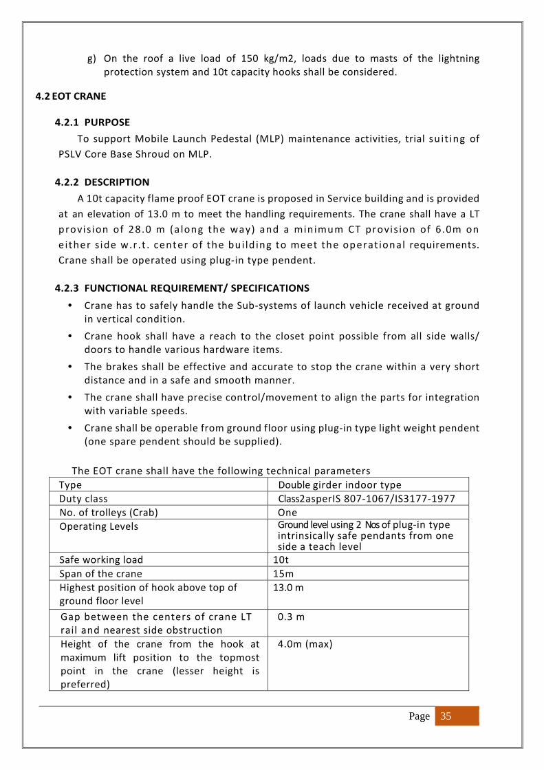
Page 35
g) On the roof a live load of 150 kg/m2, loads due to masts of the lightning
protection system and 10t capacity hooks shall be considered.
4.2 EOT CRANE
4.2.1 PURPOSE
To support Mobile Launch Pedestal (MLP) maintenance activities, trial su it ing of
PSLV Core Base Shroud on MLP.
4.2.2 DESCRIPTION
A 10t capacity flame proof EOT crane is proposed in Service building and is provided
at an elevation of 13.0 m to meet the handling requirements. The crane shall have a LT
provision of 28.0 m (a long the way) and a min imum CT provis ion of 6.0m on
e ither s ide w.r .t . center of the bui ld ing to meet the operat ional requirements.
Crane shall be operated using plug-in type pendent.
4.2.3 FUNCTIONAL REQUIREMENT/ SPECIFICATIONS
• Crane has to safely handle the Sub-systems of launch vehicle received at ground
in vertical condition.
• Crane hook shall have a reach to the closet point possible from all side walls/
doors to handle various hardware items.
• The brakes shall be effective and accurate to stop the crane within a very short
distance and in a safe and smooth manner.
• The crane shall have precise control/movement to align the parts for integration
with variable speeds.
• Crane shall be operable from ground floor using plug-in type light weight pendent
(one spare pendent should be supplied).
The EOT crane shall have the following technical parameters
Type Double girder indoor type
Duty class Class2asperIS 807-1067/IS3177-1977
No. of trolleys (Crab) One
Operating Levels Ground level using 2 Nos of plug-in type intrinsically safe pendants from one side a teach level
Safe working load 10t
Span of the crane 15m
Highest position of hook above top of
ground floor level
13.0 m
Gap between the centers of crane LT
rail and nearest side obstruction
0.3 m
Height of the crane from the hook at
maximum lift position to the topmost
point in the crane (lesser height is
preferred)
4.0m (max)
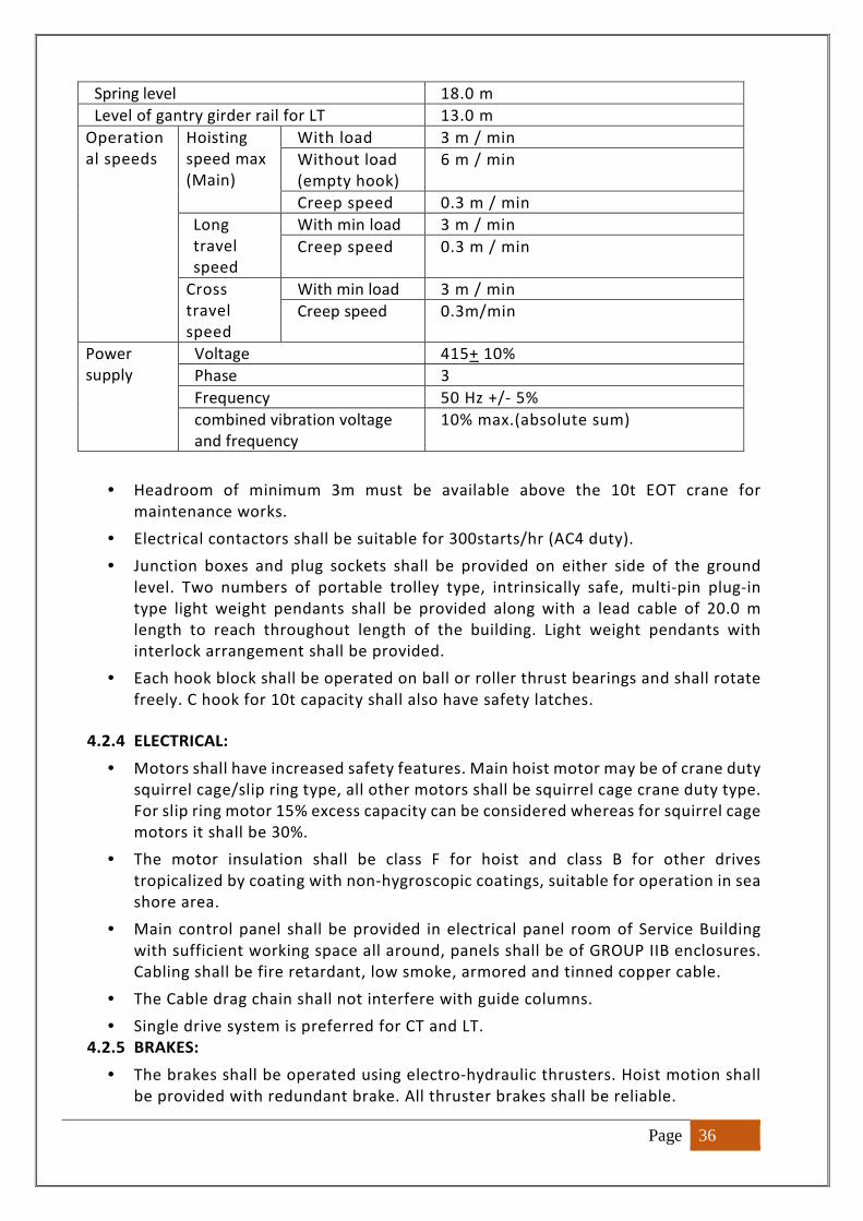
Page 36
Spring level 18.0 m
Level of gantry girder rail for LT 13.0 m
Operation
al speeds
Hoisting
speed max
(Main)
With load 3 m / min
Without load
(empty hook)
6 m / min
Creep speed 0.3 m / min
Long
travel
speed
With min load 3 m / min
Creep speed 0.3 m / min
Cross
travel
speed
With min load 3 m / min
Creep speed 0.3m/min
Power
supply
Voltage 415+ 10%
Phase 3
Frequency 50 Hz +/- 5%
combined vibration voltage
and frequency
10% max.(absolute sum)
• Headroom of minimum 3m must be available above the 10t EOT crane for
maintenance works.
• Electrical contactors shall be suitable for 300starts/hr (AC4 duty).
• Junction boxes and plug sockets shall be provided on either side of the ground
level. Two numbers of portable trolley type, intrinsically safe, multi-pin plug-in
type light weight pendants shall be provided along with a lead cable of 20.0 m
length to reach throughout length of the building. Light weight pendants with
interlock arrangement shall be provided.
• Each hook block shall be operated on ball or roller thrust bearings and shall rotate
freely. C hook for 10t capacity shall also have safety latches.
4.2.4 ELECTRICAL:
• Motors shall have increased safety features. Main hoist motor may be of crane duty
squirrel cage/slip ring type, all other motors shall be squirrel cage crane duty type.
For slip ring motor 15% excess capacity can be considered whereas for squirrel cage
motors it shall be 30%.
• The motor insulation shall be class F for hoist and class B for other drives
tropicalized by coating with non-hygroscopic coatings, suitable for operation in sea
shore area.
• Main control panel shall be provided in electrical panel room of Service Building
with sufficient working space all around, panels shall be of GROUP IIB enclosures.
Cabling shall be fire retardant, low smoke, armored and tinned copper cable.
• The Cable drag chain shall not interfere with guide columns.
• Single drive system is preferred for CT and LT.
4.2.5 BRAKES:
• The brakes shall be operated using electro-hydraulic thrusters. Hoist motion shall
be provided with redundant brake. All thruster brakes shall be reliable.
Page 37
4.2.6 DESIGN:
• Crane structure shall be designed in accordance with IS: 807 with its latest edition
/ revision.
• Mechanical, electrical, inspection and testing requirements shall be in accordance
with latest IS: 3177.
• All electrical equipment and fittings shall be suitable for ZONE-I operation as per
IS: 5572. Enclosures wherever specified shall be of GROUP IIB. Intrinsically safe
apparatus and circuits, wherever specified, shall belong to category I Band shall be
as per IS: 5780. The temperature classification shall be T4 of IS: 8239.
4.2.7 DESIGN AND STRUCTURAL CONSTRUCTION GENERAL
• In the design of components on the basis of strength, factor of safety shall not be
less than five (5) based on ultimate strength, impact, fatigue, wear and stress
concentration factors shall be taken into account.
• Wherever applicable the crane shall be rigid in construction and all movements
shall be smooth and non-jerky.
• Design shall provide for easy maintenance of all parts particularly the wheel
bearings on end-trucks. Necessary safe and sufficient working space shall be
provided all around the sub systems for easy maintenance.
• Where any portion of the structure is not free to expand or contact under variation
of temperature, allowance shall be made for stress resulting from these conditions
and the co-efficient of expansion for each degree centigrade variation of
temperature above and below normal being taken as 0.000012 for mild steel. The
maximum range of variation of temperature shall be given. Clause 8 of Section II of
IS: 800-code of practice for use of structural steel in General facility construction
shall also apply.
• For load carrying members the component plates, bars, angles and other rolled
sections, the minimum preferable thickness shall be 4.9mm (6 SWG). For unsealed
tubes the minimum thickness shall be 8 mm. The chequered plates for platforms
shall be of minimum 6 mm thick.
• Unless otherwise specified, only welded joints shall be used. Where welding is not
practicable, turned and fitted bolts shall be used. Connection between carriages
and main girders shall be by means of machined bolts fitted in reamed holes.
Minimum number of turned and fitted bolts in connection shall not be less than
two.
• Splices shall be designed to resist one and half times the forces and moments to
which they are subjected to, but in no case it shall be less than 2/3rd of the
effective strength of the material spliced except that splices in the webs of the
plate girders shall be designed for full strength of the web in shear as well as
bending. For splicing tension members, the net section of the splice plate shall be
ten percent more than that of the material spliced. Splices shall be proportioned
and arranged, so that the gravity axes of the splices are in line with the gravity axis
of the member to avoid eccentricity.
RUNWAY / TROLLEY RAILS
Page 38
• The rail section shall be as per IS: 3443 BRIDGE GIRDER
• The crane shall be of double girder type.
• The bridge girder shall be of box section. The exterior surface shall be smooth and
free from projections, so as to minimize dust collection on it.
• In bridge girder strength calculations, the trolley rails and chequered plates shall
not be considered as load carrying members.
RULING DIMENSIONS & RATIO
• For compression members, the slenderness ratio shall not exceed 120. In case of
other load carrying members and subsidiary members slenderness ratio shall not
exceed 180.
• For girders, the following values of maximum span to depth ratio shall be
governing:
Plate girders : Span/Depth= 18
Lattice girders : Span/Depth=12
DEFLECTIONS AND CAMBER
• The total maximum vertical deflection of the girders for the live load plus trolley
and not including impact or dead load of the girder shall not exceed limit of (span
÷ 1000).
• The girders shall be cambered by an amount equal to the maximum deflection due
to dead load plus one half the live load and trolley
LIFTING HOOK BLOCK ASSEMBLY
• The lifting hook block assembly shall be point hook with adequate capacity and
shall be of forged steel construction. Each hook shall be supported on ball or roller
thrust bearing and shall rotate freely on its bearing by manual operation. The lifting
hook shall have a safety latch.
• A gravity actuated pendulum type verticality indicator shall be incorporated to the
hook block.
BRAKES
• Flame proof type thruster brakes of suitable rating to stop the crane within a very
short distance and in a safe and smooth manner. They should be equally effective
in both directions.
• Double-shoe type service brake shall be provided for each motion of the crane.
These brakes shall be directly applied automatically to the motor shaft when power
supply to the drive motor is cut-off or fails. The brakes shall be equally effective in
both directions of rotation. Two brakes each rated 1.5 times of motor rated torque/
suitable capacity shall be provided for hoist motions of both hooks.
• Service brake for hoist motions shall be adequately sized to arrest and hold at rest
any load up to and including test load at any position of the lift. For hoist motion,
redundant brake is required to be provided and the capacity shall be such that each
brake can satisfactorily meet the requirements of the braking.
Page 39
• Brake drum shall be positively locked in position so as not to prevent lateral
movement by means or retainer plates or any other means.
• Thrusters shall have reserve of at least 30% stroke length available for necessary
adjustment.
• All brakes shall have smooth braking capability to decelerate in safe manner to
avoid any derailment even when applied at maximum speed. The braking action of
hoist motion shall be such that there shall not be any jerks for the objects being
lifted at main speed.
EMERGENCY MODE OPERATION
• An emergency stop pushbutton shall be provided in the intrinsically safe pendent.
On operation of this push-button all electro-hydraulic brakes shall be applied
immediately to all motions.
• Each hoist motion shall be provided with self-contained, sturdy, automatic braking
system to prevent over speeding of the hoist. These over speed brakes may be
mechanical load brake type, AC regenerative or DC dynamic type as per standard
of the manufacturer.
MOTORS
• The requirements of crane motors shall be of either increased safety or flame proof
electric motors suitable for the operating environment given in the respective
specifications of the individual cranes.
• All crane motors shall be totally enclosed, fan cooled type.
• Each motor shall have requisite capacity for intended service. The increased safety
hoist motors shall be rated to lift 125% of the design load on the hook at main
speed. The inertial rotating load shall include the rotor portion of creep motors
also.
• Hoist motor may be of squirrel cage/ slip ring type, all other motors shall be squirrel
cage type. For slip ring motors 15% excess capacity can be considered whereas for
squirrel cage motors it shall be30%. The increased safety motors shall be designed
for crane duty requirement of frequent starting, reversing and braking. The motor
pull out torque shall not be less than 2.20 times rated torque.
• Motor shall suit the duty Class S5, cyclic duty factor 40% and number of starts per
hour 300.
• In the hoist motion, where empty hook drive is specified, if the main motor is in
the drive link during the operation of the empty hook drive, the main motor shall
have the capacity to rotate at higher speed of empty hook drive motor without any
damage to rotor windings of main motor with sufficient margins.
CONTROLLERS AND REDUNDENT CONTROL SWITCHES
• Fully magnetic control shall be provided for hoist motion, long travel and cross
travel motions, complete with contactors, time lag relays, resistors and other
accessories to meet the control requirements given in specification.
• Flame retardant control cables from the crane shall be brought out by Cable Drag
Chain arrangement to a junction box located near the LT rails. The control cables
Page 40
from this junction box shall be connected to suitable intrinsically safe junction
boxes with multi pin plug sockets and hinged covers to be provided at two sides of
ground floor.
• Portable trolley mounted intrinsically safe, multi-pin plug -in type pendants shall
be provided along with a Flame retardant lead cables of 20m length to plug the
same at any of the plug sockets at various ground levels. Where more than one
pendent is provided for a crane, interlock arrangement shall be provided, so that
at any given instant crane can be operated using only one pendent.
• Suitable locking facility shall be provided between the socket and plug such that at
no instance the plug can come out of the socket inadvertently. All apparatus and
circuits contained inside the pendant push button station, junction boxes, plug
sockets etc., shall be intrinsically safe and shall belong to the category IB, as per
IS:5780. The degree of protection offered by the enclosure to the pendant push
button station shall be IP: 55 as per IS: 2147.
• Push button shall be spring return type, with 2No+2 NC contacts rated 10A, 110V
AC. Indicating lamps shall be filament type with low watt consumption lamp and
provided with series resistor.
4.3 DOORS
4.3.1 PURPOSE
To close the openings on Service building front and rear sides in such a way that
MLP is protected from the inclement weather conditions from outside and a
controlled environment is maintained inside for carrying out MLP refurbishment
activities.
4.3.2 DESCRIPTION
For carrying out the MLP refurbishment activities & PSLV sub-systems trial suiting
activities in Service building, MLPs are brought inside through the doors provided on
both sides of the building. The configuration and design of the doors shall be such
that even in case of cyclone, water or wind gust should not enter the Service building.
4.3.3 FUNCTIONAL REQUIREMENT
• Doors shall provide clear opening for the movement of MLP (MLP anchor point) on
SPU from the front side which is facing towards north. On the rear side, clear opening
shall be provided for the movement of the MLP and subsystems on SPU.
• Doors shall withstand cyclonic winds and the mechanism shall be operable at 18 m/s
wind velocity.
• Doors in closed condition need to protect the MLP and vehicle sub-systems in service
building from cyclonic winds and rain.
• Doors shall have perfect sealing at intra door interfaces as well as interface with the
building walls to prevent leakage of rain water into service building even during cyclone
in between adjacent doors, tongue and groove interface maybe considered.
• The operation of each door shall be independent without any constraint.
Page 41
• The Horizontally Sliding Doors shall be designed for the following load conditions:
� Self-weight, wind loads and acceleration loads.
� Vertical loads: Dead load has to be computed based on the unit weight of
materials as per IS: 1911. Dead weight of door structure shall be considered for
the design of the associated sub-systems.
� Cyclonic wind loads considered in the civil structure design, are to be considered
here as well.
� Operating wind loads at wind velocity of 18m/s for the drive system
� Acceleration and deceleration loads at the rate of 0.03 m/s2
� The following load combinations may be considered for designing of door
structure:
Case I: Dead load + Cyclonic wind load
Case II: Dead load + operational wind load + inertial loads
� Minimum speed of operation of doors: 2 m/min
� The drive motor shall be suitable for duty class S4, cyclic duration factor 40%
and number of starts/hour 10.
• Caving in of the doors shall be designed so that overall deflection of the service building
structure shall not affect the operation of doors
• In closed condition, the matching edge of the two halves of each door shall be within
the following tolerances:
Lateral mismatch in the direction along the track 10 mm
Vertical mismatch 10 mm
Parallelism between two edges 10 mm
4.3.4 DOOR LEAVES REQUIREMENT
• Door leaf design shall minimize the tractive effort required under operational wind
loads.
• Each door leaf shall be fully cladded with GI plain/ corrugated sheets for withstanding
cyclonic winds as per IS: 875
• Each door leaf shall overlap with adjacent door leaf as well as facility structure
appropriately and shall provide water leak dynamic joint. These joints are also to be
maintenance free. The sealing arrangement to be provided for each leaf shall ensure a
waterproof joint even during cyclone, when all doors are closed.
• Relief provided in the far end cladding to clear end stops on rails shall also be covered
appropriately to prevent entry of water and birds.
4.3.5 CYCLONE LOCKS
• Additional cyclone locks shall be provided if required, to lock the doors with facility
structure. Cyclone locks shall be easily approachable from inside for locking and
unlocking and necessary approach platforms are to be provided if required.
Page 42
4.3.6 DRIVE MECHANISM
• The drive system shall be electrically operated enabling the opening and closing of the
doors to desired limits.
• Overload protection shall be provided in the system.
• Though specific codes and standards on design of this particular item are not available,
the codes and standards followed for the design of EOT cranes shall be followed.
• For the purpose of service classification, the mechanism under consideration shall be
treated as equivalent to mechanism Class 2 of IS 807.
4.3.7 ELECTRICAL
• The selected HP rating of motors shall have a margin of 30% over calculated HP
requirement to take of deviations of calculated deviations of dead weight etc.
• One Local Control Panel (LCP) for control of each half of the door shall be provided with
all components and auxiliary contacts required and wire them.
4.3.8 SAFETY REQUIREMENTS
• The drive system for horizontally sliding doors shall be provided with travel limit
switches of flame proof type. The enclosure shall be of IP: 56 type.
• For all the sub-systems of the door, suitable approaches need to be provided both for
operation and maintenance.
• Effective guards shall be provided for all the rotating parts. All electrical equipment
should be properly guarded for protection against accidental contact.
• All electrical items shall be of flame proof construction.
4.3.9 PROPOSED CONFIGURATION
• It is proposed to provide two pairs of Horizontal Sliding Doors (HSDs), one on the front
side between EL 0.0 and EL 10.0 and other pair on the rear side between EL 0.0 and EL
10.0. The size of doors and number of pairs of doors against the clear opening required
for the movement of MLP on SPU are given below:
Details of door size and required clear opening sizes
Location Door Clear
opening(m)
Width of each
leaf (m)
Height
(m)
Total
height (m)
Front side HSD-1 14.0 8.0 10.0 10.0
Rear side HSD-2 14.0 8.0 10.0 10.0
The general arrangement of doors is shown in figure-13 & 14
• The door drive mechanisms and the local control panels are placed on floors between
portal frames for easy approach and maintenance. The ropes are taken through guide
pulleys from door ends to the rope drum and wound on it thereby establishing link
between the door and drive mechanism.
• To prevent the movement of doors in lateral direction and to support brackets with
horizontal guide, wheel assemblies are to be provided from facility floor beams at
Page 43
appropriate levels.
• The doors are operated electrically from local control panel located near the respective
drive system. Door operation shall be carried out manually also by operating the input
shaft of the drive system with a suitable handle.
• Suitable protection hood shall be provided on the top of the door to prevent rain water
entry through door/wall interface.
5. MOBILE LAUNCH PEDESTAL (MLP) 5.1 PURPOSE
It provides the platform for vehicle integration at Integration building,
transportation of launch vehicle from Integration building to MST using bogie on rail
track and support vehicle during lift off.
5.2 DESCRIPTION
The Mobile Launch Pedestal is a steel structure of 10X10 m size and 7.267m
height. It provides a working platform level at 5.5m EL for vehicle integration
activities. The launch pedestal shall be designed taking into account the self-weight,
TPS weight, dead weight of the vehicle along with operating wind loads, dynamic
loads, during transportation on curved rail track, jet loads and its temperature during
launch. Launch Pedestal has to accommodate propellant & pneumatic circuit for stage
servicing. The general arrangement of MLP shown in figure-16, 17 & 18. Clamping
provision for the vehicle during movement shall be provided on MLP.
5.3 FUNCTIONAL REQUIREMENTS/SPECIFICATIONS
Configuration of Launch Pedestal systems, consists of three units
1. Base structure
2. Central Annular Structure (CAS)
3. Anchoring Interfaces
� BASE STRUCTURE:
The functional requirement of the base structure is to provide support to the
vehicle through the spacer unit and support brackets. It is steel structure of 10 m X
10 m cross section and 5.5 m height. It includes 4 legs of 2.0 m height, one at each
corner, to anchor MLP to ground anchor points whenever required. It includes deck
of 3.5m height, which houses propellant pipelines & fire lines. The total deck has to
be divided into 3 portions with middle portion of 2m height for enabling the personnel
entry during maintenance and servicing. The deflection criteria specified, shall be
ensured in view of the critical requirements of launch vehicle alignment. Suitable cut-
outs are to be provided on Launch Pedestal for the flow of exhaust jets from the strap-
ons. Suitable cut-out closures are to be provided. The bottom surface of deck should
be rigid and suitable for jacking and also shall not have any protrusions for anchoring.
� CENTRAL ANNULAR STRUCTURE (CAS):
It is a circular steel structure of height 1.767 m. It includes a replaceable
interfacing ring of height 295mm. The function of CAS is to transfer the vehicle load
Page 44
to the base structure. It houses pipelines routed from MLP deck to Vehicle. Refractory
cement coating of 50mm is planned inside and outside of CAS to withstand jet loads.
� ANCHORING SYSTEM:
As MLP is a movable type, it needs to be anchored at specified locations. For this,
MLP legs should be suitable for anchoring to ground side interface. This anchoring
system should be rigid. At MST, the anchoring system shall be capable of withstanding
the vehicle lift off loads also.
� LOADS TO BE CONSIDERED: The following are the major loads to be considered,
1. Self-Weight of MLP
2. Dead load on MLP (750kg/m2) on top of deck.
3. Live loads: 250 kg/m2.
4. Load on the cut-out covers: 250 kg/m2.
5. Wind Loads (30m/s)
6. PSLV Weight (350t)
7. Jet Loads
8. Acoustic load
9. Temperature load
10. Skew load
11. Solar radiation
12. Support settlement loads, if any
13. Dynamic loads (including Wind Loads) during transportation on curved rail track
of 1.5 km
14. Loads during anchoring and de-anchoring of MLP
15. Inertial loads during movement may be calculated for the vehicle speed of
10m/min.
� The MLP has to be designed for static, non-linear, dynamic & buckling cases.
� The CAS top surface shall be leveled for achieving the levelling accuracy of ±30 arc
seconds.
� The maximum allowable deflection at the centre of CAS centre shall be 0.5mm.
� Acceleration during movement of MLP shall be ± 0.03 m/sec2.
� Dynamic response of the overall structure during movement shall be analyzed.
� Stiffness of structure shall be more than 1.7x 10⁶ kg/cm.
� Load Cases:
Case : 01: Dead load + Live Load + Wind load
Case : 02: PSLV load + Dead load + Live Load + Wind load ( in any direction).
Case : 03: PSLV load + Dead load + 4 strap-on firing with worst wind case
Note: Thrust of the Strap-on : 700Kn
Case : 04: Support settlement by 1.5mm for case 01 or 02, when one of the anchor
legs sunk by 1.5mm.
6. BOGIE SYSTEM PURPOSE
Wheel bogie is meant to support the MLP at its bottom during its movement from PIF
to Mobile Service Tower (MST). It consists of four nos. of wheel bogie units at four corners.
Page 45
Schematic view of bogie is shown in figure-21, 22 & 23.
DESCRIPTION
Bogie system consists of 4no.s of bogies at each corner with two nos. of 1.0 m diameter
(approximately) double flanged wheels. The system shall ensure equal load distribution on
all the wheels of the bogie. The bogie shall have parking brakes. Bogie is provided with the
hydraulic jack for lifting and lowering of MLP. All the four jacks are operated using the power
pack system mounted on bogie frame structure. The power pack system comprises of two
power packs interconnected and each power pack is capable of operating all the four jacks.
FUNCTIONAL REQUIREMENTS/SPECIFICATIONS
• The bogie system shall support the total dead load of the MLP, equipment loads, vehicle
loads, live loads and wind loads caused due to structural interactions and support
settlement.
• The bogie shall be capable of carrying the MLP at controlled speed at a wind velocity of
30 m/s. The wind may be acting from any direction.
• The jacking system capable of lifting the MLP along with the vehicle by means of hydraulic
jacks for transferring the MLP on to anchors and vice versa shall be provided on the bogie.
• The bogie shall have suitable interface to attach MLP at its bottom.
• The bogie is designed in such a way that it enters the space available in-between the legs
of the MLP and centers itself with MLP center.
6.1 STRUCTURAL CONFIGURATION
• Bogie is designed to carry the weight of the MLP along with fully integrated PSLV which is
the order of 350t.
• Bogie specifications are given below:
Capacity of bogie system 800 t
Location of Bogie system below MLP At corners of 7.5m x 7.5m
Width of the track 7.5m C/C
Tread diameter of wheels 1.0m
Load carrying capacity of each wheel 125t
No. of wheels in each corner of bogie 2 no’s
Total no. of wheels in bogie 4x2 = 8 no’s
• For ascertaining the workmanship, one wheel need to be destruct tested based on the
requirement.
• Load equalization system is to be provided for all the wheels comprising of one hinged
balancer below which two axles with oscillating blocks are provided.
• To enable the bogie to negotiate curved track, suitable bearing system shall be
Page 46
introduced.
• Suitable parking brake system shall be provided for bogie system. Suitable interface shall
be provided on either side of the bogie system for push/pull operation using SPU.
• Double flanged wheels shall be provided to take all lateral loads for negotiating the
proposed curved track.
6.2 HYDRAULIC JACKING SYSTEM
• Jacks and power pack shall be of imported and reputed make. The jacks are located one
at each corner, as part of bogie
• Capacity of hydraulic jack: 300 t X 4 no’s
Stroke 150 +/- 5 mm (nominal)
Closed shut height To suit to Bogie and MLP interface
Type Double acting
Ram Screwed type with lock nut provision
Operation Remotely operated from power pack
• Saddle: Maximum diameter 300 mm, swiveling type with anti-skid top surface
• Hose connection: From power pack to the jacks, hoses of high pressure thermoplastic
type of suitable length are to be provided. The end connections shall be of QC/DC type
with male connection on the jacks and power pack end.
• Size of cylinder: Maximum of 500 mm OD, size of the ram, operating
pressure can be suitably designed to accommodate the overall size as given above. Test
pressure shall be 1.5 times the design working pressure.
• Rate of lift or lowering under load: 10 mm/min. All the 4 jacks shall be synchronized to
operate simultaneously.
• Outside surface of ram and inner surface of cylinder shall be honed and hard chrome
plated.
• The seals should be reliable and everlasting type.
• The locknut on the ram shall be designed to take care of the full load and overload
• The inlet valve to the jack shall be pilot operated type to take care of hose failure.
• One pressure gauge has to be fixed at the jack to monitor the cylinder pressure.
• The jack shall be mounted on a suitable trolley for easy maneuverability inside the wheel
bogie.
• The hydraulic oil used shall be fire retardant.
6.3 POWER PACK FOR JACK OPERATION
• Two power packs are interconnected and each shall contain a pumping unit with hydraulic
high pressure radial plunger type piston pump operated by flame proof electric motor.
Split flow piston pump with two identical outlets is preferred.
• The oil tank shall have an oil level indicator, oil cum air breather, return line filter, drain
plug etc.
• The power pack also shall have safety relief valves, non-return valves, oil distributer with
Page 47
flow control and shut off valve with inlet to pump and outlets to four jacks.
• Flame proof DOL starter and cable of suitable length shall be provided.
• Provision for supplying oil to the pilot operated check valve near jacks to be made.
• The power pack shall have a manual pumping provision with quick interchange facility.
The manual pump shall operate with effort less than 35kg and shall provide the rated lift
in 5 min of pumping.
• The power pack shall supply oil under pressure for operation of pilot operated check
valve.
6.4 ELECTRICAL SYSTEMS
Electrical system is to be designed considering the operational loads because of jack
power packs and shall confirm to group IIB classification.
7. SELF PROPELLING UNIT (SPU)
7.1 SCOPE:
Tractive effort required shall be computed and required Interfaces on MLP shall be
provided.
7.2 PURPOSE:
The SPU is meant for the following intended purposes operated in between
Integration Building, FLP and Service Building.
a) To pull / push empty Bogie system on curved track.
b) To pull / push Bogie and Mobile Launch Pedestal (MLP) on single rail track system.
c) To pull / push Bogie, Mobile Launch Pedestal (MLP) along with Launch Vehicle
(weighing 350t) on single rail track system.
d) SPU should lift & transport the MLP by using self-lifting & lowering capability and
transport the same by road between facilities.
7.3 DESCRIPTION:
The SPU is of hydrostatic driven type, whose hydraulic motors fitted directly to
wheels with hydraulic pumps driven by diesel engine. Drive system with suitable
electronic control for regulating speed, acceleration/deceleration, braking, steering
shall be considered. The SPU is connected to MLP by means of a Push / Pull tow bar.
7.4 FUNCTIONAL REQUIREMENTS/ SPECIFICATIONS
• It shall have sufficient tractive effort on road to haul MLP with vehicle on single
rail track system.
• Its operation shall be smooth, jerk free and shall be of precise control.
• Speed control through potentiometer for achieving infinite variable speeds.
• SPU shall be provided with sufficient Ballast weight on its chassis to avoid tyre
Page 48
slippage in wet and dry conditions, between Integration Building & FLP
• The acceleration and deceleration of the SPU shall be limited to a maximum of
0.003g.
• It shall have a payload capability, for carrying with required factor of safety.
(Approximately 375t).
• It shall be of self-loading and unloading type with a stroke length of 300mm(min.).
• To arrive required tractive effort, the following weights shall be assumed:
Weight of the Bogie
Weight of the Mobile Launch Pedestal
Weight of the Launch Vehicle (350t)
Self-Weight of the SPU
• Dynamic load input to be considered for obtaining tractive effort:
Longitudinal gradient : 0.5 degree
Transverse gradient : 0.5 degree
Radius of curvature of curved track : 250 meter
Wind speed : 30 m/s
• Maximum speed of transportation: 5 kmph in laden condition, 10 kmph in un-
laden condition
7.5 SALIENT FEATURES PROPOSED IN THE SPU
• Self-propelled Modular Transporter type.
• Provided with Self lifting & lowering capability.
• Two driving modes
� One drive mode is for normal activity of transportation like MLP movement.
� Second driving mode is for Launch Vehicle transportation with
i. Normal speed
ii. Creep speed
• No jerks should occur even at sudden acceleration / deceleration / sudden braking
or while applying Emergency brake.
• SPU should move, stall with time lag during Launch Vehicle transportation.
• Provided with Wheel drive motors of sufficient capacity and also shall be capable
of Push / Pull Launch Vehicle, in the event of two drive motors fails also (in any
side).
• Dual Electronic control cards with a changeover system shall be provided in-built.
• Can be operated with Remote control using acceptable RF frequency.
• Operator presence sensing system in the operator’s cabin.
8. RAIL TRACK SYSTEM
PURPOSE
The fully integrated launch vehicle has to be moved from integration building to
First Launch Pad (FLP) on a Mobile Launch Pedestal using bogie. To meet this
requirement, a sturdy track capable of taking bogie wheel loads are to be laid
Page 49
between integration building and FLP.
DESCRIPTION
The rail track with 7.5m gauge is considered for PIF Project. The length of track
is 1500 m. Track extends from integration building to FLP. The area between the rail
tracks is to be paved with RCC road to enable movement of the SPU used for MLP
traction. Provisions are to be provided along the track for monitoring the movement
of MLP along with the vehicle through CCTV. Suitable lighting is provided on both
sides of the track.
8.1 CIVIL STRUCTURE OF SINGLE RAIL TRACK
8.1.1 PURPOSE:
To withstand the loads during the movement of launch vehicle along with MLP,
bogie and hauler over rail track.
8.1.2 DESCRIPTION:
The foundation provides a platform for laying rail track. It is provided for
supporting rail track. The length of rail track is 1500 m.
8.1.3 FUNCTIONAL REQUIREMENTS/ SPECIFICATIONS
• The track shall be designed to provide leveled top surface for smooth
movement of MLP.
• The difference in levels of top surface of track due to deflection under
load shall be minimum to maintain the stability of vehicle.
• The track shall be designed for a bogie wheel load of 125 t.
• Center to center distance of track is 7.5 m
• Level difference across tracks between rail tops at any location to be
limited to ±1 mm.
• The proposed track has to extend beyond Jet Deflector Duct (JDD) at FLP
and shall be suitably interfaced with JDD.
• The track proposed for PIF is curved with a radius of curvature of 250m.
There shall be no abnormal rubbing of the wheels on the edges of the
track which may give rise to vibrations or cause any detrimental effect
on the bogie wheels or the track.
• The track crossings shall be provided at required locations.
• RCC road with drainage provision shall be planned between the rail
tracks.
• At water bodies and hume pipes locations, necessary bridging is to be
provided.
The track layout at JDD interface is shown in figure: 01,19 & 20.
Foundation should be realized based on following conditions:
• Total weight to be carried out on rail track (800 t approx.)
• Radius of Curvature of track is 250 m
• Angle of turn is 147 degrees.

Page 50
8.2 RAIL TRACK SUB-SYSTEMS
8.2.1 PURPOSE:
Rail track sub-systems provide rigid support during the movement of launch vehicle along
with MLP, bogie and hauler.
8.2.2 DESCRIPTION:
Rail track sub-system will be anchored to the civil foundation. Once the sub-systems are
assembled, they will be an integral part of the foundation and will provide rigid support
for launch vehicle or MLP movements.
8.2.3 The following will form the track sub system:
SOLE PLATE:
Sole plate is an interfacing structural member between the rail bottom and concrete
foundation. It shall have provisions for mounting with foundation fasteners through track
foundation. The final integration of soleplates with track foundation shall be carried out
together to enable proper alignment of foundation fasteners with soleplate interfaces.
RESILIENT PAD:
Resilient pad shall be provided between the rail and soleplate to provide smooth load
transfer to track foundation. The resilient pad shall have long life to withstand for SHAR
environmental conditions.
RAIL CLIPS:
Rail clips shall be provided to hold the rail track through sole plate. The pitch and
pattern of rail clips shall be optimized as per designer load conditions suitable for curved
track.
RAIL:
MRS-85 or equivalent rail, capable of withstanding the above loads as mentioned in
section 8.1.
8.3 ANCHORING SYSTEM
8.3.1 PURPOSE:
To provide fixing of MLP at Launch Pad, Integration building, Service building and
track junction locations.
8.3.2 DESCRIPTION:
Anchoring system is to be provided for enabling assembly of MLP to ground anchors.
It involves fixing of MLP to Ground interfaces during vehicle integration activities at
integration building, service building, FLP, parking and track junction location. Anchoring
points at FLP has to be designed considering the FLP JDD, UT & MST interfaces and also
launch jet loads.
8.3.3 FUNCTIONAL REQUIREMENTS/ SPECIFICATIONS
• All anchors shall be at same level to meet the MLP leveling accuracy.
• System shall be capable of fixing MLP to ground anchors to withstand launch loads
Page 51
at MST.
• System shall be designed to carry the loads of vehicle, MLP, MLP top surface loads
during vehicle integration at PIF Integration building.
• At Service building, the anchors shall be designed for the load of MLP & Live loads.
• Positional accuracy of ground anchors should be + 1mm.
9. ELECTRICAL SYSTEMS Following are the electrical systems proposed for PIF
• PIF building electrical system
• Service building electrical system
• Auxiliary building electrical system
• PTR building electrical system
• AC plant electrical system
• The document provides details about the philosophy of normal power/DG/UPS/EPS
distribution and earthing requirements. The details of equipment and power ratings are not
included in the document, which will come as part of detailed design document
DEFINITIONS:
• ELECTRICAL SYSTEMS: The power distribution scheme of the PSLV Integration
Facilities (PIF) and associated equipment which ensure reliability, availability and
clean power within acceptable tolerance limits to the PIF and associated facilities
fall under the electrical systems of PIF. This is categorized into two forms of
electrification i.e., external electrification and internal electrification.
• EXTERNAL ELECTRIFICATION: Constitutes establishing of suitable capacity sub-station
if required with the equipment’s such as transformers, DG sets with day & UG diesel
tank, HT & LT switch gear panels, UPS systems, batteries, battery chargers,
incoming HT cable and outgoing LT cable feeders to PIF.
• INTERNAL ELECTRIFICATION: Constitutes MV panels, MCCs, LDBs, PDBs lighting,
centralized emergency lighting, area lighting, street lighting, cabling, earthing and
lightning protection systems with in the facilities including cabling for
Normal/DG/UPS.
9.1 EXTERNAL ELECTRIFICATION:
The power supply can be broadly classified as:
• Normal Power Supply in two chains (AP Transco Power Source)
• Captive Power Supply in two chains (Local DG Source)
• Uninterrupted Power Supply in two chains (UPS)
• Emergency Power Supply (EPS-Inverter Power)
It is required to design power distribution scheme based on individual maximum
demands of PIF and its associated facilities to be fed by the sub-station,
installation of transformers, HT and LT panels, switchgear protection equipment,
earthing systems and outgoing feeders to facilities, centralized emergency lighting
systems of PIF etc. Two feeders from two modules of MV panel are proposed to cater
Page 52
the PIF. The capacities of these feeders need to be designed as per the capacity each
facility. Spare switchgear at least one in each rating have to be incorporated in the
distribution panels.
9.2 INTERNAL ELECTRIFICATION:
Internal electrification is classified into three areas. One is power distribution for
illumination, power outlets, air conditioning, etc., second is power distribution for
mechanisms like motors, pumps and other critical loads etc. and third is for UPS loads
like instrumentation & control loads, fire detection, gas & pollution monitoring system
and EPS for centralized emergency lighting, CCTV, Timing etc. distribution of all
facilities.
9.3 POWER SUPPLY AND NETWORK DETAILS
Power distribution of PSLV Integration facilities take place at Low Tension (LT). The LT
Power supplies are broadly classified as:
• NORMAL POWER SUPPLY ( 415 V , 3 PHASE AC SYSTEM)
• EMERGENCY POWER SUPPLY THROUGH DG SETS (415V, 3PHASE AC SYSTEM)
• UN INTERRUPTABLE POWER SUPPLY (400V, 3 PHASE AC SYSTEM)
• EMERGENCY POWER SUPPLY (400V, 3 PHASE AC SYSTEM)
9.4 AREA CLASSIFICATION:
Various units are classified as below in order to facilitate selection of equipment in these
areas. The classifications are hazard zone as per IS – 5572, Flame proof group as per IS – 2148,
temperature classification as per IS 8239:
Sl.NO Facility Area Classification
1. Integration Facility Flameproof IIB
2. Service Facility Flameproof IIB
3. CTR Non Flameproof
4. AC Plant Non Flameproof
5. Substation Non Flameproof
6. Security and Communication Facility Non Flameproof
7. Any other Facilities Non Flameproof
9.5 INTERNAL ELECTRIFICATION REQUIREMENTS:
A. Integration Facility-PIF
Sl.NO Description Specification
1. MVP Power Distribution for entire facility
DB’s Secondary Power Distribution for entire facilities
MCCs Control of Motors for various equipment
2. Machine/Equipment Various equipment like Electrical Overhead Travel
cranes, Sliding Doors, Platforms, Lifts etc
3. Air Conditioning AHU loads
4. Illumination Around Vehicle: 350 lux at a distance of 1m.
All other areas: 250 lux in portal area of fixed platforms
and 150 lux in catwalks.
Page 53
Emergency lighting Throughout PIF including catwalks, lifts,
staircase, panel rooms, working platforms, fixed
platforms etc. with lamps.
Aviation Lamps Suitable aviation lamps/ aircraft warning with
redundancy has to be planned as per ICAO standards.
Street/Garden/ Track/
Area Lighting
Adequate Illumination with suitable aesthetic light
fixtures (with 1. High mast Lightings, 2. Street Lightings,
3. Garden Lightings 4. Warning Lighting etc.)
5. Power Sockets Distribution Power through power sockets
Single phase 16A
Power outlet /
plug and sockets
4 Numbers of Power sockets in each floor on either side
3 Phase,32A
Power outlet /
plug and sockets
One Number power sockets in each floor on either side.
3 Phase,63A Power
outlet / plug and
sockets
One number of power sockets required either side in
alternate floor
3 Phase,250A Power
outlet / plug and
sockets
Two Number of Power Outlet in ground floor.
3 Phase,32A Power
outlets
Provision for water pumps all along rail track and in and
around PIF have to be planned.
Water coolers Single phase in the portal areas.
6. UPS Power
requirement
(2 Chain
Configuration with
Isolation
Transformer)
Single phase 16A Power outlets/plug sockets points:
• 40 points distributed at platform levels
• 10 points I&CS
7. EPS
(Single Chain
Configuration
with Isolation
Transformer)
Single phase 16A Power outlets/plug sockets points:
• 40 points distributed at platform levels
• 10 points I&CS
• 16 points for Automation
• 20 points for CCTV
• 10 points for timing
• 10 points for FDA
• 20 points for Communication
• 02 points for High Speed Camera
• 04 points for Technical Documentation
8. Ventilation
Wall mounted Air
circulators
160 numbers air circulators
Exhaust fans For all panel and rest rooms

Page 54
9. Type of Cabling /
Wiring
Armoured/Flexible copper cable in suitable GI perforated
routed through cable trays up to 16 sqmm size. Above this
size aluminium cable routed through cable trays
10. EARTHING (Static/
Power /
Instrumentation)
Independent earthing scheme for static <1ohm,
Instrumentation <1 ohm and power <5 ohm with 150 ohm/mtr
soil resistivity
Driven earth pipes of 50 mm NB/6-12 mtr long may be
considered.
Copper interconnecting strips for static and instrumentation.
And GI for all other interconnections.
Rail Track Earthing at suitable intervals throughout the length
of the track as per standards.
11. Lightning Protection Standard lightning protection as per IEC/BIS shall be provided
and with vertical air termination on the roof of PIF with
horizontal conductors suspended over the length and with
suitable down conductors, and earth pits.
Transient earth clamps / potential equalizing clamps shall be
provided between lightning earth pits and other pits.
B. Service Building
Sl.NO Description Specification
1. MVP Power Distribution for entire facility
DB’s Secondary Power Distribution for entire facilities
MCCs Control of Motors for various equipment
2. Machine/Equipment Various equipment like Electrical Overhead Travel cranes,
Sliding Doors, Lifts, etc.
3. Illumination 250 lux in all area and 150 lux in catwalks.
Emergency lighting Throughout Service building including catwalks, lifts,
staircase, panel rooms etc. with lamps.
4 Power Sockets Distribution Power through power sockets
Single phase 16A
Power outlet /
plug and sockets
4 Numbers of Power sockets in each floor on either
side
3 Phase,32A
Power outlet /
plug and sockets
One Number power sockets in each floor on either
side.
3 Phase,63A Power
outlet / plug and
sockets
One number of power sockets required either side in
ground floor
3 Phase,250A Power
outlet / plug and
sockets
Two Number of Power Outlet in ground floor.
Water coolers Single phase in the portal areas.
Page 55
5. EPS
(Single Chain
Configuration
with Isolation
Transformer)
Single phase 16A Power outlets/plug sockets points:
• 4 points distributed at both floors
• 4 points I&CS
• 6 points for Automation
• 4 points for FDA
• 2 points for Communication
• 04 points for Technical Documentation
6. Ventilation
wall mounted Air
circulators
26 numbers air circulators
Exhaust fans For all panel and rest rooms
7. Type of Cabling /
Wiring
Armoured/Flexible copper cable in suitable GI perforated
routed through cable trays up to 16 sqmm size. Above this
size aluminum cable routed through cable trays
8. EARTHING (Static/
Power /
Instrumentation)
Independent earthing scheme for static <1ohm,
Instrumentation <1 ohm and power <5 ohm with 150
ohm/mtr soil resistivity
Driven earth pipes of 50 mm NB/6-12 mtr long may be
considered.
Copper interconnecting strips for static and instrumentation.
And GI for all other interconnections.
9. Lightning Protection Standard lightning protection as per IEC/BIS shall
be provided.
C. Auxiliary Buildings
Sl.NO Description Specification
1. MVP Power Distribution for entire facility
DB’s Secondary Power Distribution for entire facilities
MCCs Control of Motors for various equipment if required
2. Machine/Equipment Various equipment like Pump Motors etc.
3. Illumination 300 lux in working/ office area and 150 lux in corridors.
Emergency lighting Throughout auxiliary buildings including corridors, portal
area, staircase, panel rooms etc. with lamps.
4 Power Sockets Distribution Power through power sockets
Single phase
6/16/20A Power
outlet / plug and
sockets
Power sockets in each room as required
Page 56
3 Phase,32A
Power outlet /
plug and sockets
Wherever required.
3 Phase,63A Power
outlet / plug and
sockets
Wherever Required
5. EPS
(Single Chain
Configuration
with Isolation
Transformer)
Single phase 16A Power outlets/plug sockets points
according to the requirement:
• 4 points distributed each room
• 6 points for Automation
• 4 points for FDA
• 4 points for Communication
• 10 points for Technical Documentation
6. Ventilation
Ceiling/wall mounted
fans
all rooms
Exhaust fans For all panel and rest rooms
Air Conditioning Split AC: Two points in each room
7. Type of Cabling /
Wiring
Concealed MS/GI Conduit wiring as per standards.
8. Lightning Protection Standard lightning protection as per IEC/BIS shall be
provided.
D. CTR-PIF
Sl.NO Description Specification
1. MVP Power Distribution for entire facility
DB’s Secondary Power Distribution for entire facilities
3. Air Conditioning AHU loads
4. Illumination All areas: 300 lux and 150 lux in corridors.
Emergency lighting Throughout CTR
Area Lighting Adequate Illumination with suitable aesthetic light
fixtures.
5 Power Sockets Distribution Power through power sockets
Single phase
6/16/20A Power
outlet / plug and
sockets
Power sockets in each room as required
3 Phase,32A
Power outlet /
plug and sockets
One Number power sockets
6 UPS Power
requirement
(2 Chain
Configuration with
• 3 phase power distribution points for checkout:
1. UMVP with isolation transformer and outgoing
feeders.
2. Remote Power ON Panels (RPOP)
• 10 points I&CS
Page 57
Isolation
Transformer)
• 6 points for Automation
7. EPS
(Single Chain
Configuration
with Isolation
Transformer)
Single phase 6/16/20A Power outlets/plug sockets
points:
• 10 points for checkout
• 10 points I&CS
• 6 points for Automation
• 2 points for CCTV
• 2 points for timing
• 2 points for FDA
• 2 points for Communication
• 4 points for Technical Documentation
8. Ventilation
wall mounted Fans 12 numbers
Exhaust fans For all panel and rest rooms
9. Type of Cabling /
Wiring
Armoured/Flexible copper cable in suitable GI perforated
routed through cable trays up to 16 sqmm size.
10. EARTHING (Power /
Instrumentation)
Independent earthing scheme for Instrumentation <1 ohm
and power <5 ohm with 150 ohm/mtr soil resistivity
Driven earth pipes of 50 mm NB/6-12 mtr long may be
considered.
Copper interconnecting strips for static and instrumentation.
And GI for all other interconnections.
11. Lightning Protection Standard lightning protection as per IEC/BIS shall
be provided.
Transient earth clamps / potential equalizing
clamps shall be provided between lightning earth
pits and other pits.
E. AC Plant-PIF
Sl.NO Description Specification
1. MVP Power Distribution for entire facility
DB’s Secondary Power Distribution for entire facilities
MCCs Control of AC Equipment for various equipment
2. Machine/Equipment Various equipment like compressors, chillers, pumps, motors,
heaters etc.
3. Air Conditioning AHU loads
4. Illumination All areas: 250 lux
and 150 lux in corridors.
Emergency lighting Throughout AC Plant
Area Lighting Adequate Illumination with suitable aesthetic light
fixtures
Page 58
5 Power Sockets Distribution Power through power sockets
Single phase
6/16/20A Power
outlet / plug and
sockets
4 Numbers of Power sockets
3 Phase,32A
Power outlet /
plug and sockets
2 Numbers power sockets
3 Phase,63A Power
outlet / plug and
sockets
2 Numbers of power sockets
6 UPS Power
requirement
(2 Chain
Configuration with
Isolation
Transformer)
Single phase 6/16/20A Power outlets/plug sockets
points:
• 10 points for Automation/DDC
7. EPS
(Single Chain
Configuration with
Isolation
Transformer)
Single phase 16A Power outlets/plug sockets points:
• 16 points for Automation
• 2 points for CCTV
• 2 points for FDA
• 2 points for Communication
• 04 points for Technical Documentation
8. Ventilation
wall mounted Air
circulators
16 numbers air circulators
Exhaust fans For all panel and rest rooms
9. Type of Cabling /
Wiring
Armoured/Flexible copper cable in suitable GI perforated
routed through cable trays up to 16 sqmm size. Above this
size aluminium cable routed through cable trays
10. EARTHING (Power /
Instrumentation)
Independent earthing scheme for Instrumentation <1 ohm
and power <5 ohm with 150 ohm/mtr soil resistivity
Driven earth pipes of 50 mm NB/6-12 mtr long may be
considered.
Copper interconnecting strips for static and instrumentation.
And GI for all other interconnections.
11. Lightning Protection Standard lightning protection as per IEC/BIS shall
be provided.
9.6 DESIGN PHILOSOPHY: • Adequate redundancy shall be incorporated throughout the distribution
• Minimum two times the rating of arrived full load for the feeder’s switchgears.
• For MCC power components; minimum two times the rating of arrived full load
rating
Page 59
• For all motor drives minimum 1.5 times the rating of arrived full load
• All light fitting shall be of energy efficient and aesthetic.
9.7 CONSTRUCTION POWER SUPPLY
Construction power at LT level will be provided at single point 250 mtr
approximately away from the site. Suitable distribution panel with standard protection,
metering, ELCB protection for each feeder and equipment is in the scope of vendor. LT
tariff for the energy consumed as per actual will be based on terms and conditions and
energy bill have to be paid / deducted periodically. Providing proper grounding for
panels, distribution, construction equipment and safe working condition as per IE rules
and recommendations is in the scope of the vendor. Periodical inspection report (once
in three months) covering all systems and health of protective systems shall be
submitted.
10. INTERNAL ROADS The following internal roads are to be considered by design consultancy,
• Integration building to FLP (RCC road in between the rail track)
• Integration building to service building (SPU movement with MLP)
• Pavement area around PIF building (SPU movement with MLP)
• Roads between various facilities in PIF complex.
11. MODIFICATIONS AT FLP
SCOPE:
To interface the existing FLP with the PIF systems like new rail track over JDD, establishment
of MLP anchoring provision and associated modifications etc.
DESCRIPTION:
First Launch Pad (FLP) is meant for integration and launch of PSLV launch Vehicle. FLP mainly
consists of Mobile Service Tower (MST), Umbilical Tower (UT), Launch Pedestal (LP) and Jet
Deflector Duct (JDD). FLP is designed based on Integrate On Pad (IOP) concept in which
vehicle will be assembled on fixed Launch Pedestal. MST will be positioned from launch pad
end for enabling launch. The general arrangement of modifications are shown in figure-19
& 20.
For realization of PIF project, present FLP has to be augmented. The following are the
modifications involved
• Design & installation of new JDD track beam over JDD for enabling movement of MLP.
• Provision for anchoring of MLP at launch pad by removing the existing LP.
• UT modifications. (Not in the scope of design consultant).
11.1 DISMANTLING OF LAUNCH PEDESTAL AND CONVERSION TO MLP ANCHORING SYSTEM
PURPOSE: To accommodate MLP along with launch vehicle, bogie and hauler at FLP-UT.
Page 60
DESCRIPTION:
PIF project involves movement of integrated vehicle on MLP from PIF FACILITY to FLP.
This introduced the concept of Mobile Launch Pedestal (MLP). Currently, Launch Pedestal
is fixed to the FLP foundation by 4 legs one at each corner. LP leg cross section is 0.8 X 0.8
m. In view of PIF project, LP has to be transformed to Mobile Launch Pedestal (MLP)
configuration.
The following works are involved:
• Removal of existing LP using suitable mechanism (not in the scope of design
consultant).
• Realization of suitable anchoring scheme for MLP and ground interfaces such that
MLP top height shall be maintained. The anchors/position of legs of existing LP shall
be used to derive the MLP anchor points.
• MLP anchoring system shall be designed to take care of the following:
� MLP levelling accuracy
� Live loads & dead loads of MLP and loads due to launch.
� It shall be easily operable.
11.2 RAIL TRACK SYSTEM ON JDD
PURPOSE: To support MLP along with launch vehicle, bogie and hauler at UT location.
DESCRIPTION:
Single rail track will be used for transportation of launch vehicle from PIF Integration
building to FLP. The proposed track is a double flange single rail track with gauge length of
7.5 m. Track starts from PIF Integration building to FLP for a length of 1500m. At FLP, track
has to cross Jet Deflector Duct over a span of 9 m. Two new track beams have to be
introduced and suitably interfaced with the existing foundation. Integrated analysis of
newly designed rail track system on JDD is to be carried out considering existing JDD and
UT foundation configuration.
11.3 UT MODIFICATIONS
PURPOSE: To accommodate the new rail track girder beam
DESCRIPTION:
Umbilical Tower is a part of First Launch Pad. It is just beside the JDD diaphragm
wall. New Rail Track is proposed over JDD having span length of 9m. To support rail
track girder beam over JDD on one side, UT needs to be modified, accordingly. Rail track
girder beam towards UT side shall have overlapping on JDD wall not beyond 1.8m.
Integrated foundation of MST anchoring JDD & UT shall be considered while designing
of track beam.
12. AUXILIARY BUILDINGS Following are the auxiliary building considered:
• Check out and Gas service building
• AC systems building
• Technical services building
• Refer figure-01 for building locations.
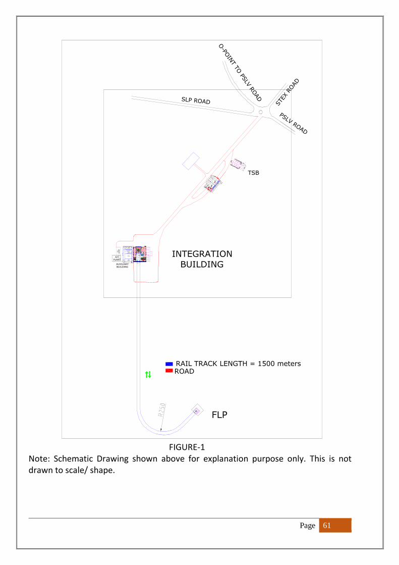
Page 61
FIGURE-1
Note: Schematic Drawing shown above for explanation purpose only. This is not
drawn to scale/ shape.
ST AIR CASE
TSB
R OOM
Pneu
matic
s erv
icin
g room
FACILI TY ROOM
SLP ROAD
ROAD
Door Mech anism
FRO
NT
LP Ac c
es s p
latfor m
VALF
Checkout
ESCAPE
CHUTE
TPS s e
r vicing
room
Pneumatic
room
Refra
ctor
y
equipmen
t
r oom
ST AI R CASE
A/CPLANT
ELEVATOR-1
TOILETS
Prop
ellan
t
s erv
icing room
FLP
W AITI NG H ALL
PSLV ROAD
Electric
al
pan
el roo
m
POR
TIC
O
Doo r Mech anism
INTEGRATION
BUILDING
REAR
Stair c a
se
ST AIR CASE
ELEVATOR-1
RIS
systems
SURVE ILLANC
E CUM
WAITING
ROOM
Tool c
rib
ESC APE
CHU TE
RAI L TRACK
GAS
CYLIN
DER
PAR
KIN
G
ELEVA TOR-2 D IS CUS SION ROOM
F ir e
wat
e r
serv
icing
room
TOILE TS
OPERATION
AL ROOMS
O-P
OIN
T T
O PS
LV R
OAD
Door Mechan ism
A/Cplant
ST AI R CASE
Door Me ch
anism
ELEVA TOR-2
Pneumatic
CONFERENCE HA
LL
Toilets
Toile
ts
FAC ILITY ROOM
STE
X R
OAD
RAIL TRACK LENGTH = 1500 meters
OPE RATIONA
L ROOMS
TOILE TS
T RACK
CEN TER
CSOG
Console
SECU RITY
AUXILIARYBUILDING
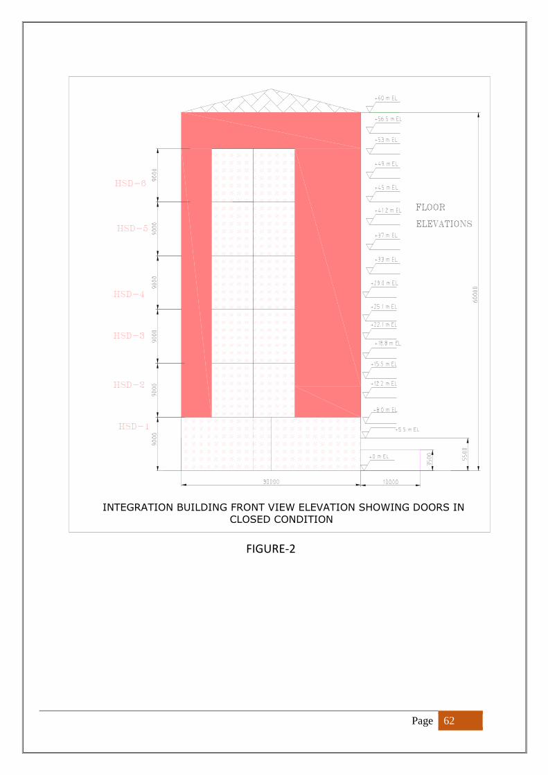
Page 62
FIGURE-2
INTEGRATION BUILDING FRONT VIEW ELEVATION SHOWING DOORS IN
CLOSED CONDITION
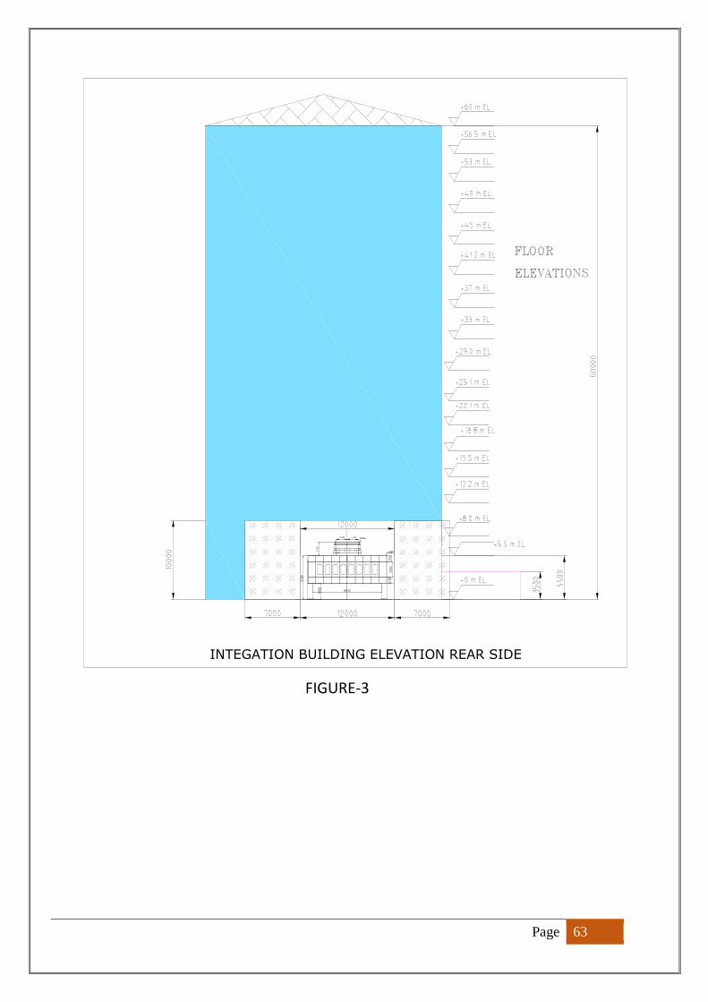
Page 63
FIGURE-3
INTEGATION BUILDING ELEVATION REAR SIDE
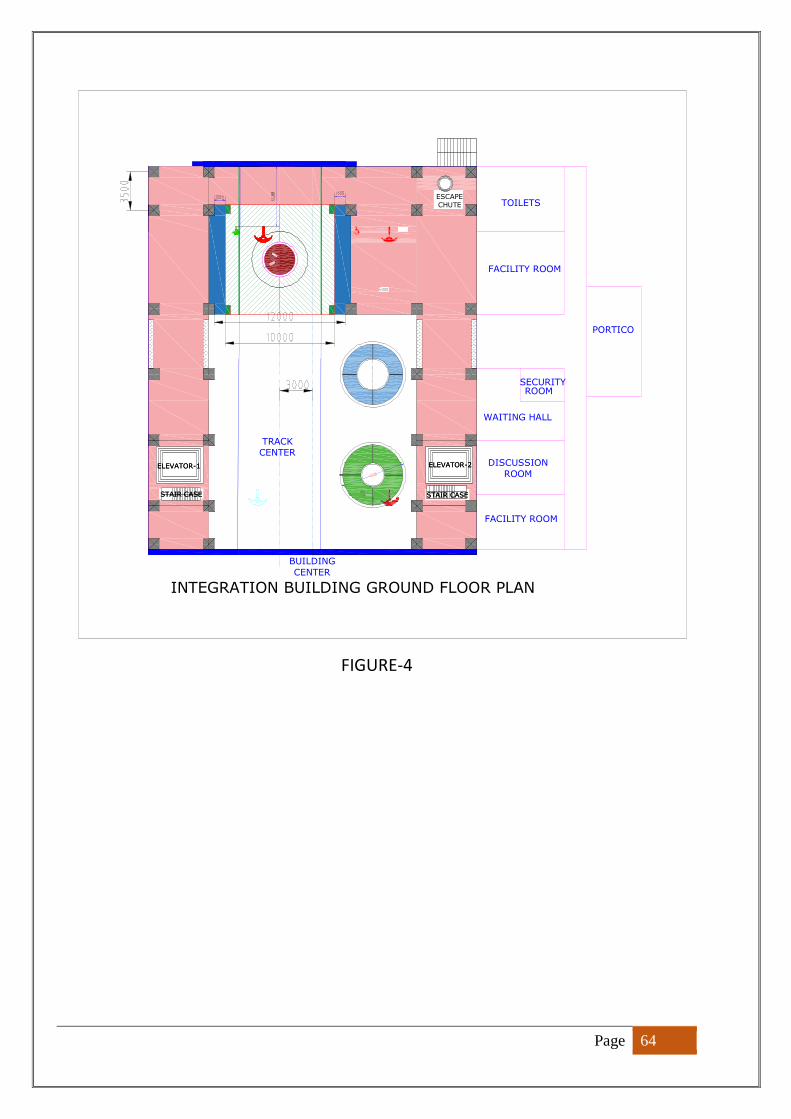
Page 64
FIGURE-4
INTEGRATION BUILDING GROUND FLOOR PLAN
ELEVATOR-2
PORTICO
ELEVATOR-1
SECURITY
FACILITY ROOM
STAIR CASE
ELEVATOR-2
STAIR CASE
ROOM
FACILITY ROOM
BUILDING
CENTER
STAIR CASE
TOILETS
WAITING HALL
ELEVATOR-1
ESCAPE
CHUTE
TRACK
CENTERDISCUSSION
ROOM
STAIR CASE
Page 65
FIGURE-5
INTEGRATION BUILDING SHOWING CRANE AND DOORS
ELEVATIONS IN CLEAR OPENING
Auxiliary Buildings
Page 66
FIGURE-6
INTEGRATION BUILDING SHOWING FLOORS &
PLATFORM ELEVATIONS
Page 67
FIGURE-7
INTEGRATION BUILDING SHOWING FLOORS &
PLATFORM ELEVATIONS
Page 68
FIGURE-8
STAIR CASE
HSD DRIVE
MECHANISM
STAIR CASE
ELEVATOR-2
ESCAPE
CHUTE
SSLV
ASSEMBLY
STAND
TRACK
CENTER
S 139
ASSEMBLY
STAND
ELEVATOR-1
RAIL TRACK
CRANE SPAN
INTEGRATION BUILDING
BASIC PLAN
BUILDING
CENTER
REAR HSD
HSD DRIVE
MECHANISM
FRONT HSD
PO
WER
CA
BLE T
RAY
CH
EC
KO
UT C
ABLE T
RAY
GAS
LIN
ES B
AY
EMERGENCY
EXIT
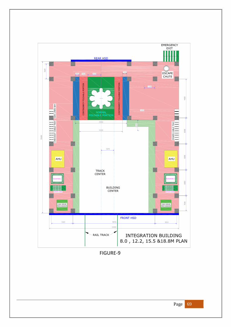
Page 69
FIGURE-9
HSD DRIVE
MECHANISM
HSD DRIVE
MECHANISM
ELEVATOR-1
CH
ECKO
UT C
ABLE T
RAY
RAIL TRACK
CO
NTIN
GN
ECY F
OLD
ABLE P
ORTIO
N
EMERGENCY
EXIT
ELEVATOR-2
PO
WER C
ABLE T
RAY
REAR HSD
TRACK
CENTER
ESCAPE
CHUTE
CO
NTIN
GN
ECY F
OLD
ABLE P
ORTIO
N
FRONT HSD
STAIR CASE
BUILDING
CENTER
NORMAL
FOLDABLE PORTION
INTEGRATION BUILDING
8.0 , 12.2, 15.5 &18.8M PLAN
GAS L
INES B
AY
STAIR CASE
AHU AHU
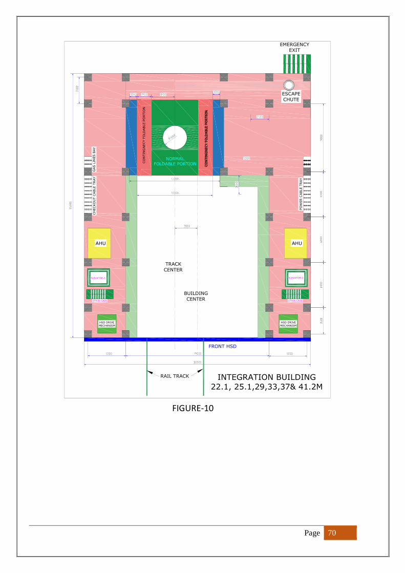
Page 70
FIGURE-10
ELEVATOR-1
STAIR CASE
BUILDING
CENTER
RAIL TRACK
ELEVATOR-2
EMERGENCYEXIT
FRONT HSD
ESCAPE
CHUTE
TRACK
CENTER
INTEGRATION BUILDING
22.1, 25.1,29,33,37& 41.2M
HSD DRIVE
MECHANISM
CH
EC
KO
UT C
ABLE T
RAY
CO
NTIN
GN
EC
Y F
OLD
ABLE P
OR
TIO
N
HSD DRIVE
MECHANISM
AHU
STAIR CASE
NORMAL
FOLDABLE PORTION
GAS L
INES B
AY
CO
NTIN
GN
EC
Y F
OLD
ABLE P
ORTIO
N
PO
WER
CABLE T
RAY
CO
NTIN
GN
EC
Y F
OLD
ABLE P
OR
TIO
N
AHU
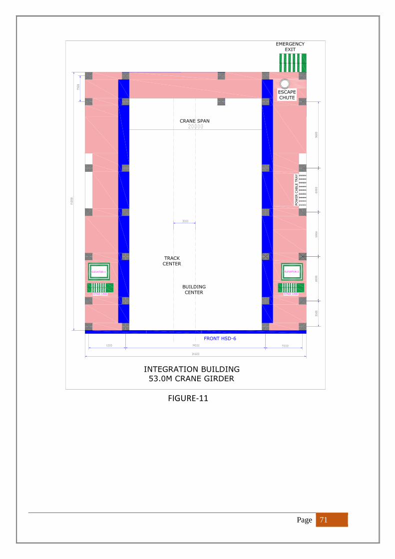
Page 71
FIGURE-11
FRONT HSD-6
ELEVATOR-1
CRANE SPAN
STAIR CASE
EMERGENCYEXIT
INTEGRATION BUILDING
53.0M CRANE GIRDER
ELEVATOR-2
PO
WER
CAB
LE T
RAY
ESCAPE
CHUTE
TRACK
CENTER
STAIR CASE
BUILDING
CENTER
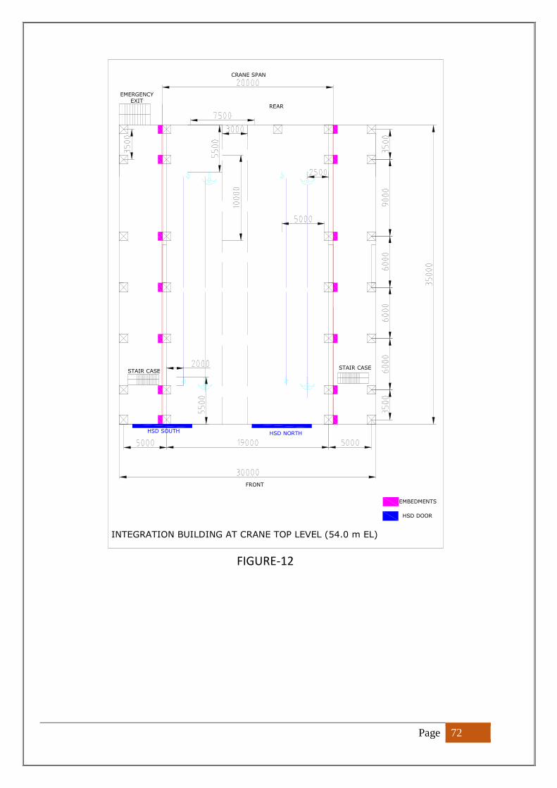
Page 72
FIGURE-12
HSD NORTH
STAIR CASE
CRANE SPAN
STAIR CASE
EMBEDMENTS
INTEGRATION BUILDING AT CRANE TOP LEVEL (54.0 m EL)
HSD SOUTH
FRONT
HSD DOOR
REAR
EMERGENCY
EXIT
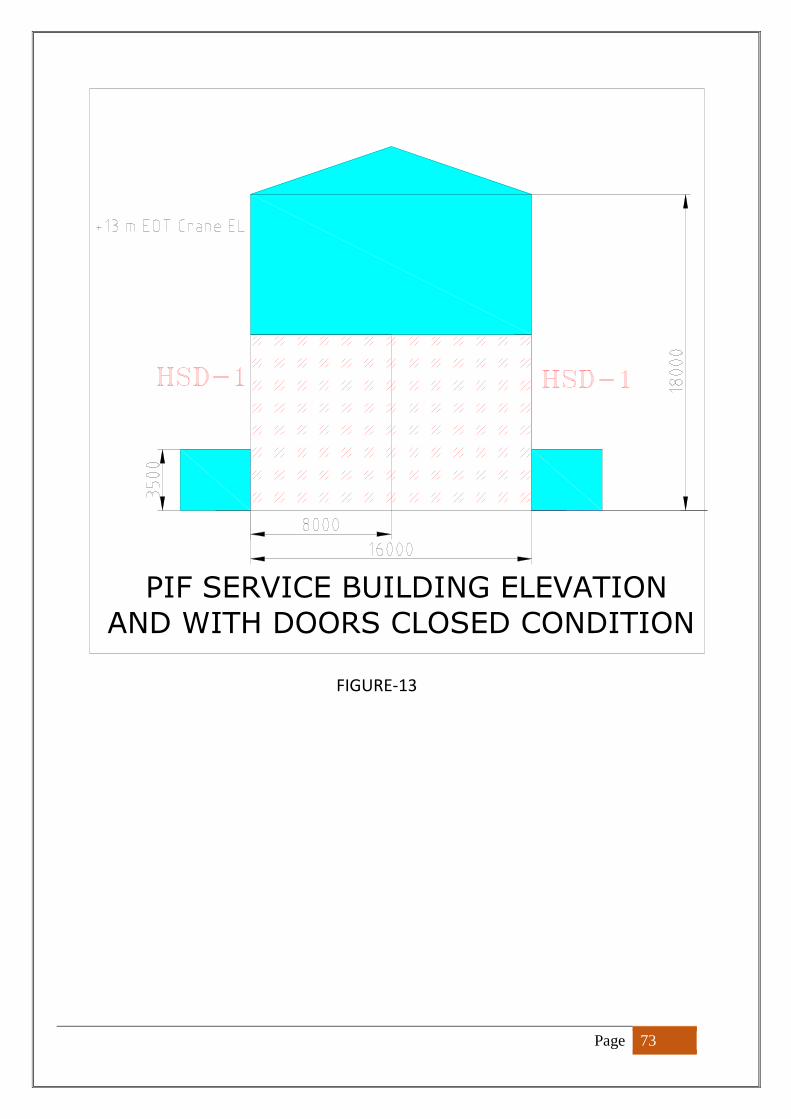
Page 73
FIGURE-13
PIF SERVICE BUILDING ELEVATION
AND WITH DOORS CLOSED CONDITION
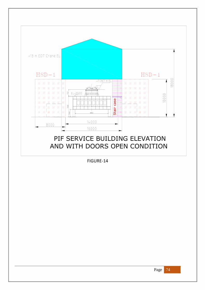
Page 74
FIGURE-14
PIF SERVICE BUILDING ELEVATION
AND WITH DOORS OPEN CONDITION
Sta
ir c
ase
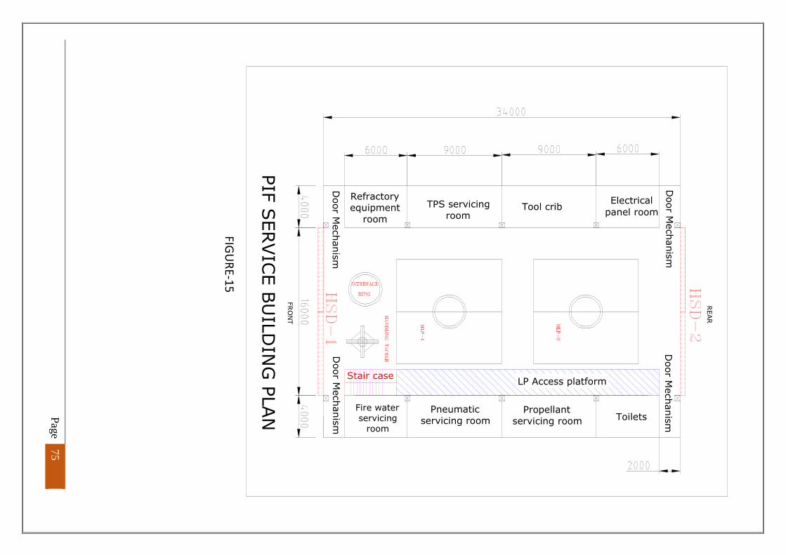
Page 75
F
IGU
RE
-15
PIF
SERVIC
E B
UIL
DIN
G P
LAN
FR
ON
T
Pneumatic
servicing room
TPS servicing
roomTool crib
REAR
Propellant
servicing room
Fire water
servicing
room
Toilets
Refractoryequipment
room
Electrical
panel room
Door M
echanis
m
LP Access platform
Door M
echanis
m
Stair case
Door M
echanis
mD
oor M
echanis
m
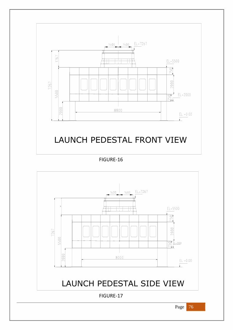
Page 76
FIGURE-16
FIGURE-17
LAUNCH PEDESTAL FRONT VIEW
LAUNCH PEDESTAL SIDE VIEW
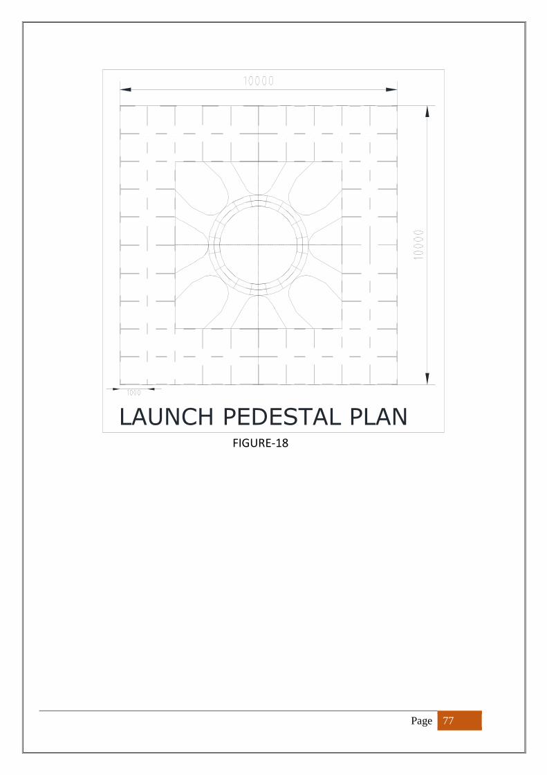
Page 77
FIGURE-18
LAUNCH PEDESTAL PLAN
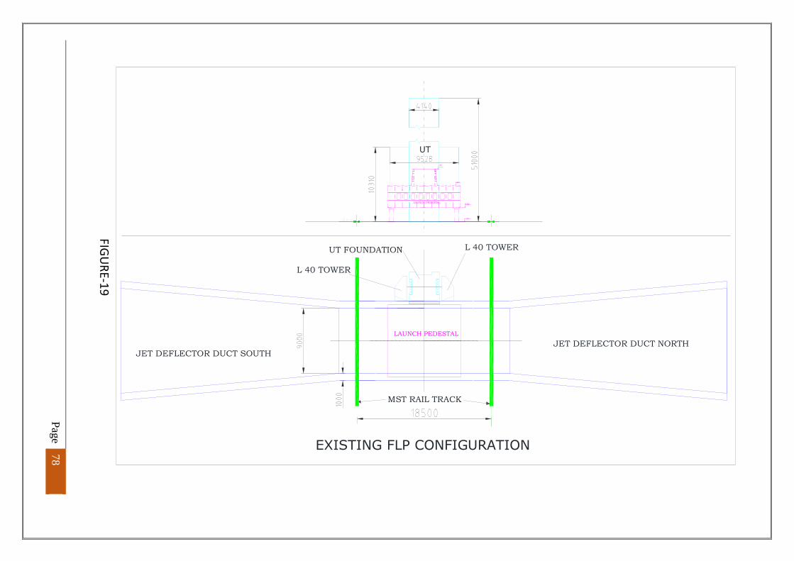
Page 78
F
IGU
RE
-19
LAUNCH PEDESTAL
LAUNCH PEDESTAL
EXISTING FLP CONFIGURATION
MST RAIL TRACK
JET DEFLECTOR DUCT SOUTHJET DEFLECTOR DUCT NORTH
L 40 TOWER
L 40 TOWER
UT FOUNDATION
UT
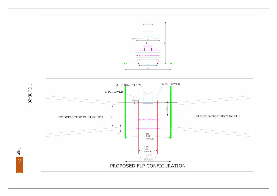
Page 79
FIG
UR
E-2
0
MSTRAILTRACK
NEWRAILTRACK
MOBILE LAUNCH PEDESTAL
PROPOSED FLP CONFIGURATION
L 40 TOWER
JET DEFLECTOR DUCT SOUTH
UT FOUNDATION
JET DEFLECTOR DUCT NORTH
L 40 TOWER
LAUNCH PEDESTAL
UT
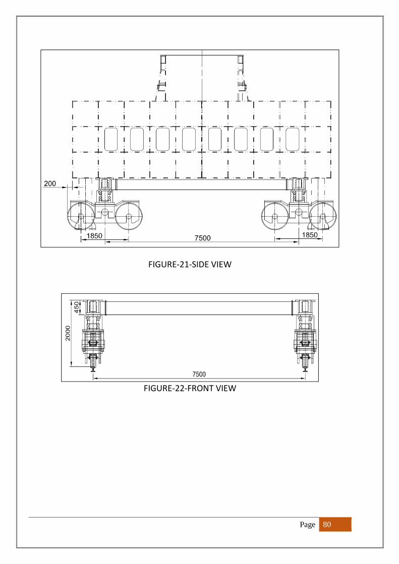
Page 80
FIGURE-21-SIDE VIEW
FIGURE-22-FRONT VIEW
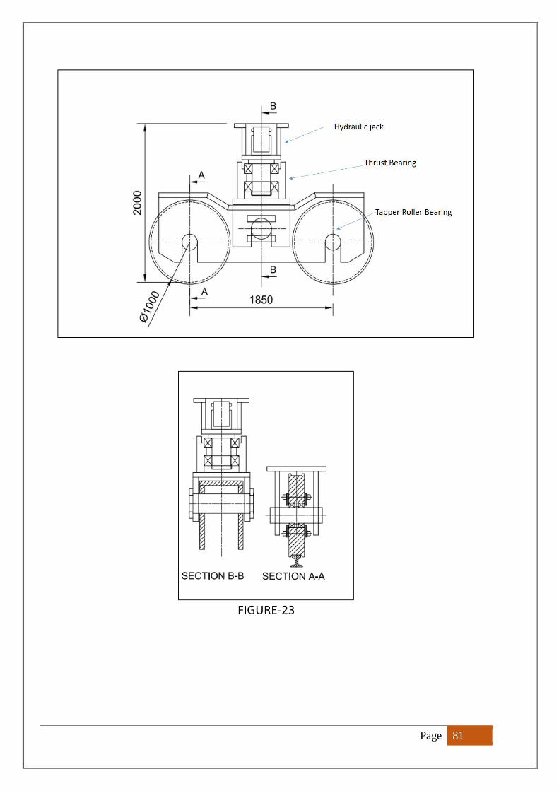
Page 81
FIGURE-23