Embed Size (px)
Citation preview

PSBEN 5012C
v.1.1
PSBEN 13,8V/5A/17Ah/EN Buffer, switch mode power supply unit Grade 3.
EN**
Edition: 9 from 27.11.2019
Supercedes edition: 8 from 31.01.2019
LED Version
www.pulsar.pl PSBEN5012C BLACK POWER
2
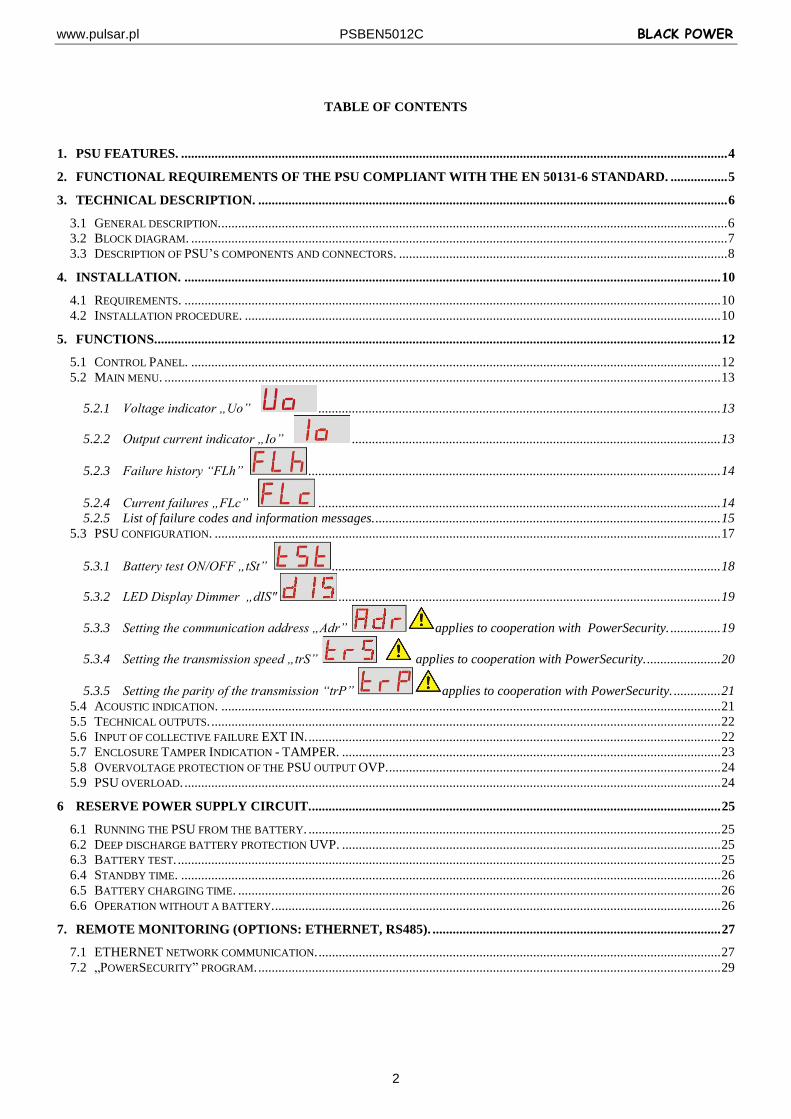
TABLE OF CONTENTS
1. PSU FEATURES. ................................................................................................................................................................... 4
2. FUNCTIONAL REQUIREMENTS OF THE PSU COMPLIANT WITH THE EN 50131-6 STANDARD. ................. 5
3. TECHNICAL DESCRIPTION. ............................................................................................................................................ 6
3.1 GENERAL DESCRIPTION. ....................................................................................................................................................... 6 3.2 BLOCK DIAGRAM. ................................................................................................................................................................ 7 3.3 DESCRIPTION OF PSU’S COMPONENTS AND CONNECTORS. .................................................................................................. 8
4. INSTALLATION. ................................................................................................................................................................ 10
4.1 REQUIREMENTS. ................................................................................................................................................................ 10 4.2 INSTALLATION PROCEDURE. .............................................................................................................................................. 10
5. FUNCTIONS......................................................................................................................................................................... 12
5.1 CONTROL PANEL. .............................................................................................................................................................. 12 5.2 MAIN MENU. ...................................................................................................................................................................... 13
5.2.1 Voltage indicator „Uo” ........................................................................................................................ 13
5.2.2 Output current indicator „Io” .............................................................................................................. 13
5.2.3 Failure history “FLh” ........................................................................................................................... 14
5.2.4 Current failures „FLc” ........................................................................................................................ 14 5.2.5 List of failure codes and information messages. ....................................................................................................... 15
5.3 PSU CONFIGURATION. ....................................................................................................................................................... 17
5.3.1 Battery test ON/OFF „tSt” .................................................................................................................... 18
5.3.2 LED Display Dimmer „dIS" .................................................................................................................. 19
5.3.3 Setting the communication address „Adr” applies to cooperation with PowerSecurity. ............... 19
5.3.4 Setting the transmission speed „trS” applies to cooperation with PowerSecurity. ...................... 20
5.3.5 Setting the parity of the transmission “trP” applies to cooperation with PowerSecurity. .............. 21 5.4 ACOUSTIC INDICATION. ..................................................................................................................................................... 21 5.5 TECHNICAL OUTPUTS. ........................................................................................................................................................ 22 5.6 INPUT OF COLLECTIVE FAILURE EXT IN. ........................................................................................................................... 22 5.7 ENCLOSURE TAMPER INDICATION - TAMPER. ................................................................................................................. 23 5.8 OVERVOLTAGE PROTECTION OF THE PSU OUTPUT OVP. ................................................................................................... 24 5.9 PSU OVERLOAD. ................................................................................................................................................................ 24
6 RESERVE POWER SUPPLY CIRCUIT. .......................................................................................................................... 25
6.1 RUNNING THE PSU FROM THE BATTERY. ........................................................................................................................... 25 6.2 DEEP DISCHARGE BATTERY PROTECTION UVP. ................................................................................................................. 25 6.3 BATTERY TEST. .................................................................................................................................................................. 25 6.4 STANDBY TIME. ................................................................................................................................................................. 26 6.5 BATTERY CHARGING TIME. ................................................................................................................................................ 26 6.6 OPERATION WITHOUT A BATTERY. ..................................................................................................................................... 26
7. REMOTE MONITORING (OPTIONS: ETHERNET, RS485). ...................................................................................... 27
7.1 ETHERNET NETWORK COMMUNICATION. ........................................................................................................................ 27 7.2 „POWERSECURITY” PROGRAM. .......................................................................................................................................... 29

www.pulsar.pl PSBEN5012C BLACK POWER
3
8. TECHNICAL PARAMETERS. .......................................................................................................................................... 30
TABLE 13. ELECTRICAL PARAMETERS. ...................................................................................................................................... 30 TABLE 14. MECHANICAL PARAMETERS. .................................................................................................................................... 31 TABLE 15. SAFETY OF USE. ....................................................................................................................................................... 31
9. TECHNICAL INSPECTIONS AND MAINTENANCE. .................................................................................................. 32
www.pulsar.pl PSBEN5012C BLACK POWER
4
1. PSU features. EN50131-6 compliance, 1÷3 grades and II
environmental class
mains supply of ~230 V
uninterrupted voltage of 13,8 V DC
fitting battery: 17 Ah/12 V
high efficiency 77%
PSU current efficiency:
1,4 A – for grades 1 , 2 *
0,56 A – for grades 3 **
5 A – for general use *** (see: chapter 3.1)
low level of voltage ripple
microprocessor-based automation system
intelligent management of PSU’s output power level
‘SERIAL’ communication port with implemented MODBUS RTU protocol
remote monitoring (option: Ethernet, RS485)
free program - ‘PowerSecurity’ for monitoring the PSU operation parameters
load current control
output voltage control
output fuse status control
dynamic battery test
battery circuit continuity control
battery voltages control
battery fuse status control
battery charge and maintenance control
deep discharge battery protection (UVP)
battery overcharge protection
battery output protection against short circuit and reverse polarity connection
jumper selectable battery charging current 0,6 A/1,5 A/2,2 A/3 A
remote battery test (additional module required)
START button for battery activation
STOP button for disconnecting during battery-assisted operation
optical indication – LED panel
output current readings
output voltage readings
failure codes with history
optical indication of PSU overload OVL
acoustic indication of failure
adjustable times indicating AC power failure
technical inputs/outputs with galvanic isolation
EXT IN input of collective failure
EPS technical output indicating AC power loss
PSU technical output indicating PSU failure
APS technical output indicating battery failure
internal memory of PSU operating status
protections:
SCP short circuit protection
OLP overload protection
OHP overheat protection
OVP over voltage protection
surge protection
against tampering: unwanted opening of the enclosure or detachment from the mounting surface
convectional cooling
warranty – 5 year from the production date
www.pulsar.pl PSBEN5012C BLACK POWER
5
2. Functional requirements of the PSU compliant with the EN 50131-6 standard.
Functional requirements
Requirements of EN 50131-6 PSBEN5012C
Grade 1 Grade 2 Grade 3 EPS network absence YES YES YES YES
Low battery voltage YES YES YES YES
Protection against complete battery discharge
- - YES YES
Battery failure - - YES YES
No battery charge - - YES YES
Low output voltage - - YES YES
High output voltage - - YES YES
PSU failure - - YES YES
Surge protection - - YES YES
Short circuit protection YES YES YES YES
Overload protection YES YES YES YES
Output fuse activation - - - YES
Battery fuse failure - - - YES
EPS technical output YES YES YES YES
APS technical output YES YES YES YES
PSU technical output YES YES YES YES
Input of collective failure - - - YES
Remote battery test - - - YES
Tamper indicating enclosure opening YES YES YES YES
Tamper indicating detachment from the mounting surface
- - YES YES
www.pulsar.pl PSBEN5012C BLACK POWER
6
3. Technical description.
3.1 General description. The buffer power supply is designed in accordance with the requirements of the EN 50131-6 standard,
grade 1÷3 and II environmental class. It is intended for an uninterrupted supply of alarm system devices requiring stabilized voltage of 12 V DC (+/-15%).
Depending on a required protection level of the alarm system in the installation place, the PSU efficiency and the battery charging current should be set as follows:
* Grade 1, 2 - standby time 12h Output current 1,4 A + 3 A battery charge ** Grade 3 - standby time 30h if the faults of the main power source are reported to the Alarm Receiving Centre - ARC (in accordance with 9.2 – EN 50131-1 standard). Output current 0,56 A + 3 A battery charge - standby time 60h if the faults of the main power source are reported to the Alarm Receiving Centre - ARC (in accordance with 9.2 – EN 50131-1 standard). Output current 0,28 A + 3 A battery charge *** General use – if the PSU is not mounted in an installation complaint with the EN-50131 standard, the acceptable current efficiency amounts to: 1. Output current 5 A + 0,6 A battery charge 2. Output current 4,1 A + 1,5 A battery charge 3. Output current 3,4 A + 2,2 A battery charge 4. Output current 2,6 A + 3 A battery charge
Total current of the receivers + battery: 5,6 A max.
In case of power decay, a battery back-up is activated immediately. The PSU is housed in a metal enclosure (color: RAL 9005 - black) with battery space for a 17 Ah/12 V battery. It is fitted with micro switches indicating unwanted door opening (front panel) and detachment from the mounting surface.
DOPTIONAL POWER SUPPLY CONFIGURATIONS: (visualization available at www.pulsar.pl)
1. Buffer power supply PSBEN 13,8 V/5x1 A/17 Ah/INTERFEJS - PSBEN 5012C + LB8 5x1 A (AWZ579, AWZ580)+17 Ah+INTERFACE 2. Buffer power supply PSBEN 13,8 V/12 V/17 Ah/INTERFACE
- PSBEN 5012C + RN500 (13,8 V/12 V)+17 Ah+INTERFACE 3. Buffer power supply PSBEN 13,8 V/12 V/5x1 A/17 Ah - PSBEN 5012C + RN500 (13,8 V/12 V)+LB8 5x1 A (AWZ579, AWZ580)+17 Ah
www.pulsar.pl PSBEN5012C BLACK POWER
7
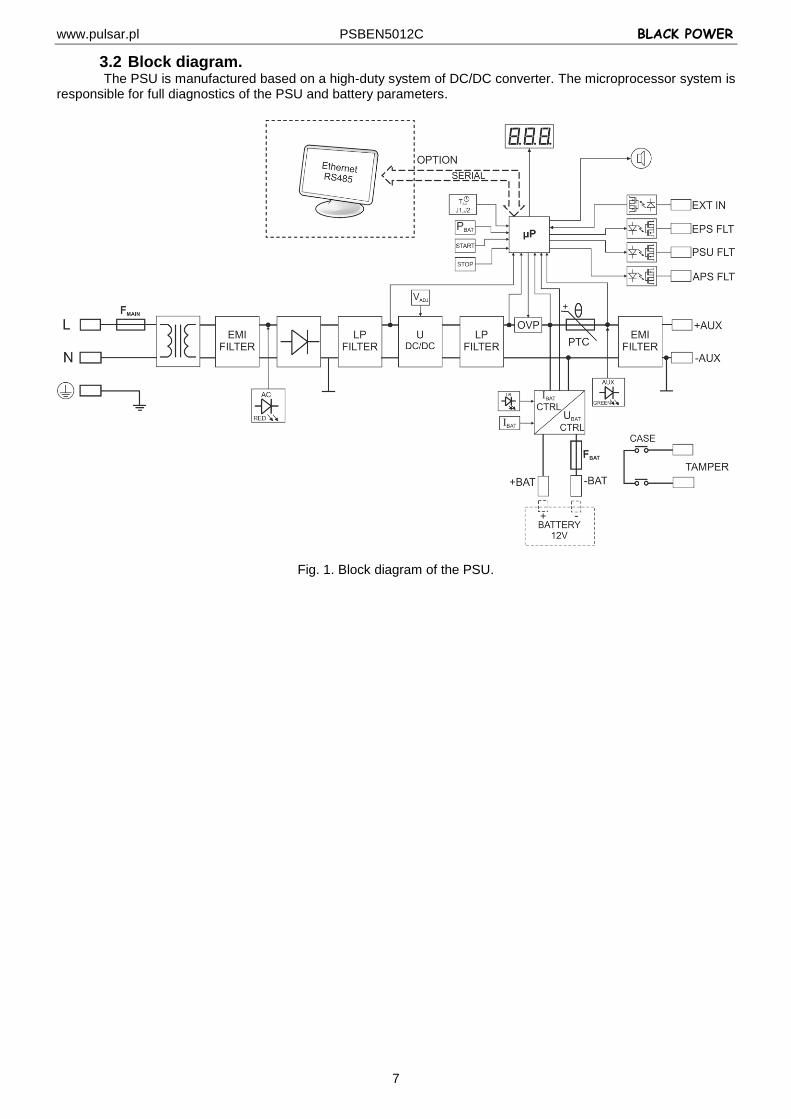
3.2 Block diagram. The PSU is manufactured based on a high-duty system of DC/DC converter. The microprocessor system is
responsible for full diagnostics of the PSU and battery parameters.
Fig. 1. Block diagram of the PSU.
www.pulsar.pl PSBEN5012C BLACK POWER
8
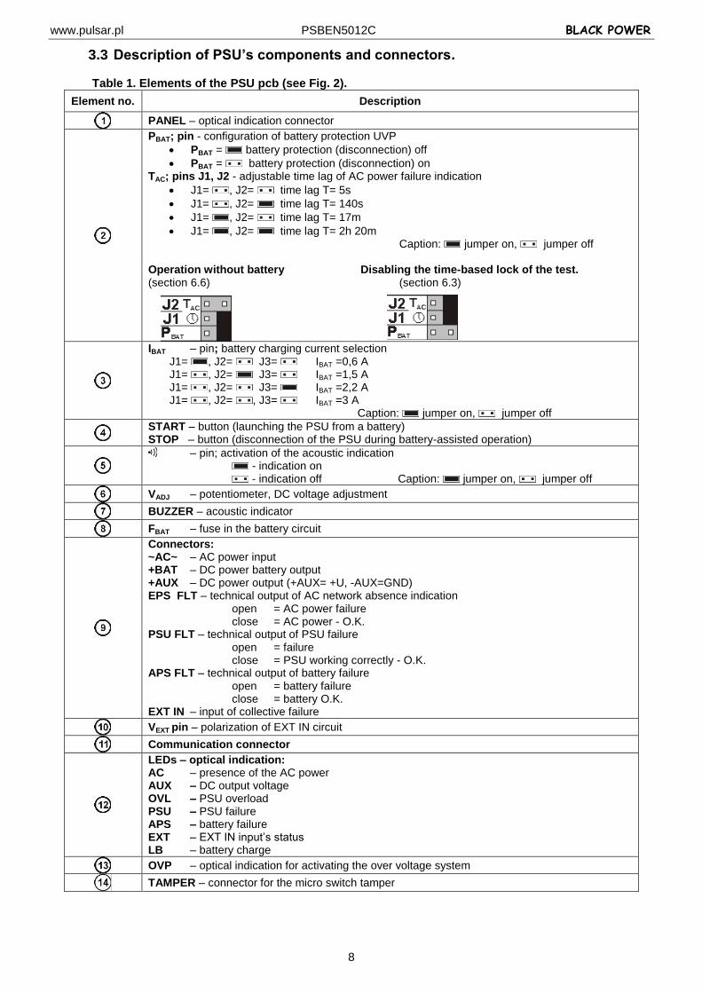
3.3 Description of PSU’s components and connectors.
Table 1. Elements of the PSU pcb (see Fig. 2).
Element no. Description
PANEL – optical indication connector
PBAT; pin - configuration of battery protection UVP
PBAT = battery protection (disconnection) off
PBAT = battery protection (disconnection) on TAC; pins J1, J2 - adjustable time lag of AC power failure indication
J1= , J2= time lag T= 5s
J1= , J2= time lag T= 140s
J1= , J2= time lag T= 17m
J1= , J2= time lag T= 2h 20m Caption: jumper on, jumper off Operation without battery Disabling the time-based lock of the test. (section 6.6) (section 6.3)
IBAT – pin; battery charging current selection J1= , J2= J3= IBAT =0,6 A J1= , J2= J3= IBAT =1,5 A J1= , J2= J3= IBAT =2,2 A J1= , J2= , J3= IBAT =3 A Caption: jumper on, jumper off
START – button (launching the PSU from a battery) STOP – button (disconnection of the PSU during battery-assisted operation)
– pin; activation of the acoustic indication - indication on - indication off Caption: jumper on, jumper off
VADJ – potentiometer, DC voltage adjustment
BUZZER – acoustic indicator
FBAT – fuse in the battery circuit
Connectors: ~AC~ – AC power input +BAT – DC power battery output +AUX – DC power output (+AUX= +U, -AUX=GND) EPS FLT – technical output of AC network absence indication open = AC power failure close = AC power - O.K. PSU FLT – technical output of PSU failure open = failure close = PSU working correctly - O.K. APS FLT – technical output of battery failure open = battery failure close = battery O.K. EXT IN – input of collective failure
VEXT pin – polarization of EXT IN circuit
Communication connector
LEDs – optical indication: AC – presence of the AC power AUX – DC output voltage OVL – PSU overload PSU – PSU failure APS – battery failure EXT – EXT IN input’s status LB – battery charge
OVP – optical indication for activating the over voltage system
TAMPER – connector for the micro switch tamper
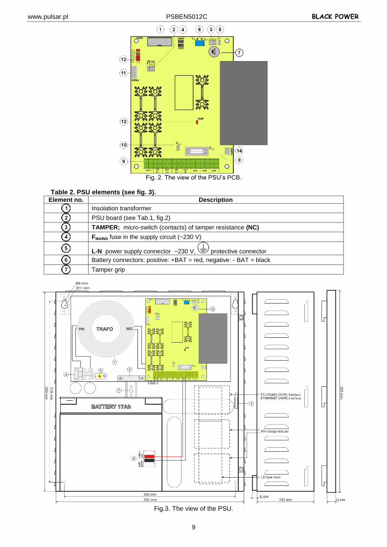
www.pulsar.pl PSBEN5012C BLACK POWER
9
Fig. 2. The view of the PSU’s PCB.
Table 2. PSU elements (see fig. 3).
Element no. Description
Insolation transformer
PSU board (see Tab.1, fig.2)
TAMPER; micro-switch (contacts) of tamper resistance (NC)
FMAINS fuse in the supply circuit (~230 V)
L-N power supply connector ~230 V, protective connector
Battery connectors: positive: +BAT = red, negative: - BAT = black
Tamper grip
Fig.3. The view of the PSU.
www.pulsar.pl PSBEN5012C BLACK POWER
10
4. Installation. 4.1 Requirements.
The PSU is to be mounted by a qualified installer, holding relevant permits and licenses (applicable and required for a given country) for ~230 V in and low-voltage installations.
As the power supply is designed for a continuous operation and is not equipped with a power-switch, therefore, an appropriate overload protection in the power supply circuit should be provided. Moreover, the user should be informed how to disconnect the power supply unit from the mains supply (usually by assigning an appropriate fuse in the fuse box). The electrical system shall be made in accordance with applicable standards and regulations. The power supply should operate in a vertical position in order to provide free and convectional air flow through ventilating holes of the casing.
4.2 Installation procedure.
CAUTION! Before installation, cut off the voltage in the ~230 V power-supply circuit. To switch off power use an external switch in which the distance between the contacts of all poles in the disconnection state is not less than 3mm.
It is required to install an installation switch with a nominal current of min. 3 A in the power supply circuits
outside the power supply unit.
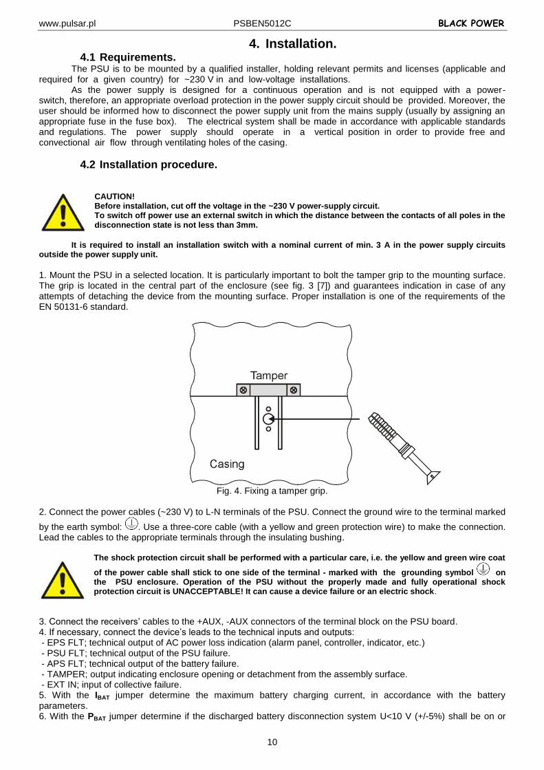
1. Mount the PSU in a selected location. It is particularly important to bolt the tamper grip to the mounting surface. The grip is located in the central part of the enclosure (see fig. 3 [7]) and guarantees indication in case of any attempts of detaching the device from the mounting surface. Proper installation is one of the requirements of the EN 50131-6 standard.
Fig. 4. Fixing a tamper grip.
2. Connect the power cables (~230 V) to L-N terminals of the PSU. Connect the ground wire to the terminal marked
by the earth symbol: . Use a three-core cable (with a yellow and green protection wire) to make the connection. Lead the cables to the appropriate terminals through the insulating bushing.
The shock protection circuit shall be performed with a particular care, i.e. the yellow and green wire coat
of the power cable shall stick to one side of the terminal - marked with the grounding symbol on the PSU enclosure. Operation of the PSU without the properly made and fully operational shock protection circuit is UNACCEPTABLE! It can cause a device failure or an electric shock.
3. Connect the receivers’ cables to the +AUX, -AUX connectors of the terminal block on the PSU board. 4. If necessary, connect the device’s leads to the technical inputs and outputs: - EPS FLT; technical output of AC power loss indication (alarm panel, controller, indicator, etc.) - PSU FLT; technical output of the PSU failure. - APS FLT; technical output of the battery failure. - TAMPER; output indicating enclosure opening or detachment from the assembly surface. - EXT IN; input of collective failure. 5. With the IBAT jumper determine the maximum battery charging current, in accordance with the battery parameters. 6. With the PBAT jumper determine if the discharged battery disconnection system U<10 V (+/-5%) shall be on or
www.pulsar.pl PSBEN5012C BLACK POWER
11
off. The battery protection is on when the PBAT jumper is off. 7. Switch on the ~230 V supply (red AC diode and green AUX diode should be on). 8. Check the output voltage (the PSU voltage without load and without battery should amount to 13.7 V÷13.9 V, with a battery or during battery charging process: 11.0 V÷13.8 V). If the value of the voltage requires adjustment, it should be set with use of the VADJ potentiometer, monitoring the voltage at the AUX output of the PSU. 9. Connect the batteries in accordance with the markings: +BAT red to 'plus', -BAT black to 'minus’. The LB diode should be on during battery charging process. 10. Press the STOP button to activate or deactivate a dynamic battery test. Deactivating the test turns out the PSU failure indication at the APS FLT output, but it does not affect the protection system against complete battery discharge. 11. Check the current consumption of the receivers, taking into account the battery charging current, so as not to exceed the total current efficiency of the PSU. 12. Once the tests are completed, close the PSU cover. Table 3. Operation parameters.
Environmental class II
Operating temperature -10ºC...+40ºC
Storing temperature -20ºC...+60ºC
Relative humidity 20%...90%, no condensation
Sinusoidal vibrations during operation EN 50130-5
Surges during operation EN 50130-5
Direct insolation unacceptable
Vibrations and surges during transport PN-83/T-42106
Table 4. Factory settings of the PSU.
Indication time of EPS network loss 5s section 5.5
Battery charging current 1,5 A section 6.5
Battery presence YES (battery present) section 6.6
Battery test ON section 5.3.1 section 6.3
Deep discharge battery protection UVP ON section 6.2
Acoustic indication ON section 5.4
LED display dimmer OFF section 5.3.2
Communication address 1 section 5.3.3
Transmission 115.2k 8E1 section 5.3.4 section 5.3.5
www.pulsar.pl PSBEN5012C BLACK POWER
12
5. Functions.
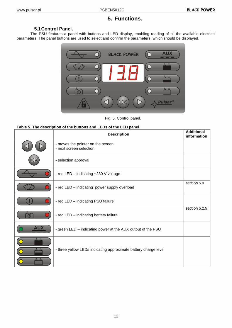
5.1 Control Panel. The PSU features a panel with buttons and LED display, enabling reading of all the available electrical
parameters. The panel buttons are used to select and confirm the parameters, which should be displayed.
Fig. 5. Control panel.
Table 5. The description of the buttons and LEDs of the LED panel.
Description Additional information
- moves the pointer on the screen - next screen selection
- selection approval
- red LED – indicating ~230 V voltage
- red LED – indicating power supply overload
section 5.9
- red LED – indicating PSU failure
section 5.2.5
- red LED – indicating battery failure
- green LED – indicating power at the AUX output of the PSU
- three yellow LEDs indicating approximate battery charge level
www.pulsar.pl PSBEN5012C BLACK POWER
13
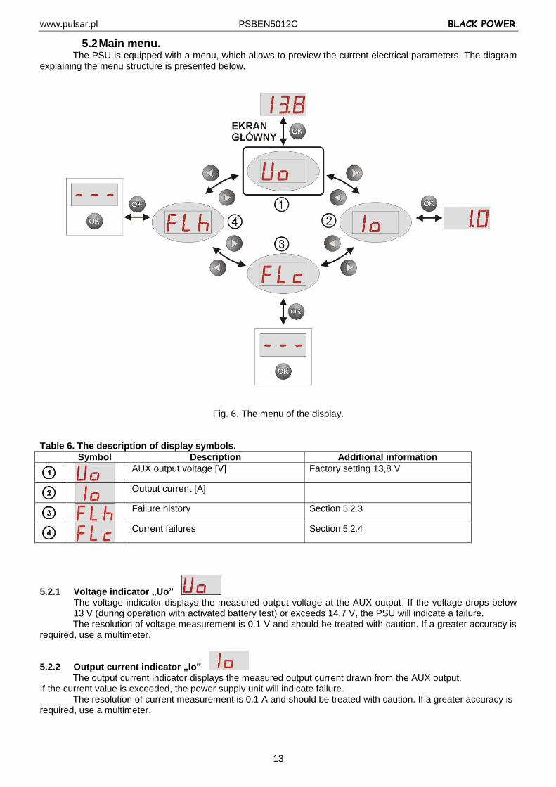
5.2 Main menu. The PSU is equipped with a menu, which allows to preview the current electrical parameters. The diagram
explaining the menu structure is presented below.
Fig. 6. The menu of the display.
Table 6. The description of display symbols.
Symbol Description Additional information
AUX output voltage [V] Factory setting 13,8 V
Output current [A]
Failure history Section 5.2.3
Current failures Section 5.2.4
5.2.1 Voltage indicator „Uo” The voltage indicator displays the measured output voltage at the AUX output. If the voltage drops below 13 V (during operation with activated battery test) or exceeds 14.7 V, the PSU will indicate a failure.
The resolution of voltage measurement is 0.1 V and should be treated with caution. If a greater accuracy is required, use a multimeter.
5.2.2 Output current indicator „Io” The output current indicator displays the measured output current drawn from the AUX output. If the current value is exceeded, the power supply unit will indicate failure. The resolution of current measurement is 0.1 A and should be treated with caution. If a greater accuracy is required, use a multimeter.
www.pulsar.pl PSBEN5012C BLACK POWER
14
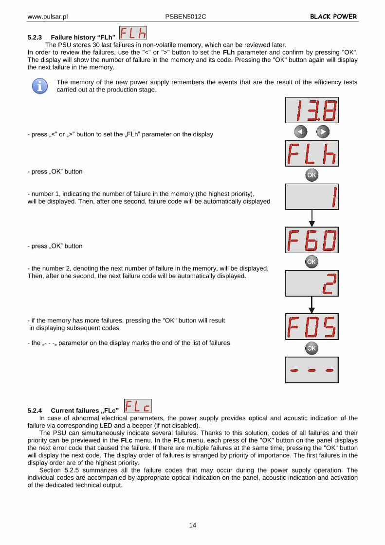
5.2.3 Failure history “FLh” The PSU stores 30 last failures in non-volatile memory, which can be reviewed later.
In order to review the failures, use the "<" or ">" button to set the FLh parameter and confirm by pressing "OK". The display will show the number of failure in the memory and its code. Pressing the "OK" button again will display the next failure in the memory.
The memory of the new power supply remembers the events that are the result of the efficiency tests carried out at the production stage.
- press „<” or „>” button to set the „FLh” parameter on the display - press „OK” button - number 1, indicating the number of failure in the memory (the highest priority), will be displayed. Then, after one second, failure code will be automatically displayed - press „OK” button - the number 2, denoting the next number of failure in the memory, will be displayed. Then, after one second, the next failure code will be automatically displayed. - if the memory has more failures, pressing the "OK" button will result in displaying subsequent codes - the „- - -„ parameter on the display marks the end of the list of failures
5.2.4 Current failures „FLc” In case of abnormal electrical parameters, the power supply provides optical and acoustic indication of the
failure via corresponding LED and a beeper (if not disabled). The PSU can simultaneously indicate several failures. Thanks to this solution, codes of all failures and their
priority can be previewed in the FLc menu. In the FLc menu, each press of the "OK" button on the panel displays the next error code that caused the failure. If there are multiple failures at the same time, pressing the "OK" button will display the next code. The display order of failures is arranged by priority of importance. The first failures in the display order are of the highest priority.
Section 5.2.5 summarizes all the failure codes that may occur during the power supply operation. The individual codes are accompanied by appropriate optical indication on the panel, acoustic indication and activation of the dedicated technical output.
www.pulsar.pl PSBEN5012C BLACK POWER
15
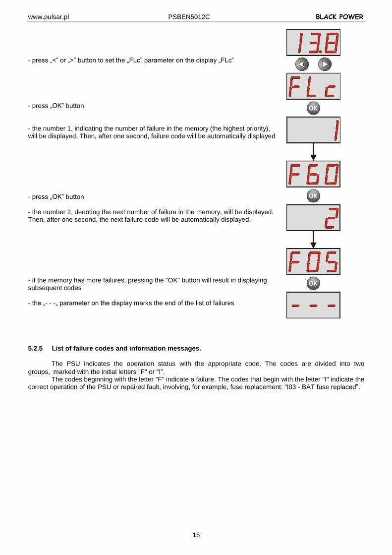
- press „<” or „>” button to set the „FLc” parameter on the display „FLc” - press „OK” button - the number 1, indicating the number of failure in the memory (the highest priority), will be displayed. Then, after one second, failure code will be automatically displayed - press „OK” button - the number 2, denoting the next number of failure in the memory, will be displayed. Then, after one second, the next failure code will be automatically displayed. - if the memory has more failures, pressing the "OK" button will result in displaying subsequent codes - the „- - -„ parameter on the display marks the end of the list of failures 5.2.5 List of failure codes and information messages.
The PSU indicates the operation status with the appropriate code. The codes are divided into two
groups,marked with the initial letters "F" or "I”. The codes beginning with the letter "F" indicate a failure. The codes that begin with the letter "I" indicate the
correct operation of the PSU or repaired fault, involving, for example, fuse replacement: "I03 - BAT fuse replaced”.
www.pulsar.pl PSBEN5012C BLACK POWER
16
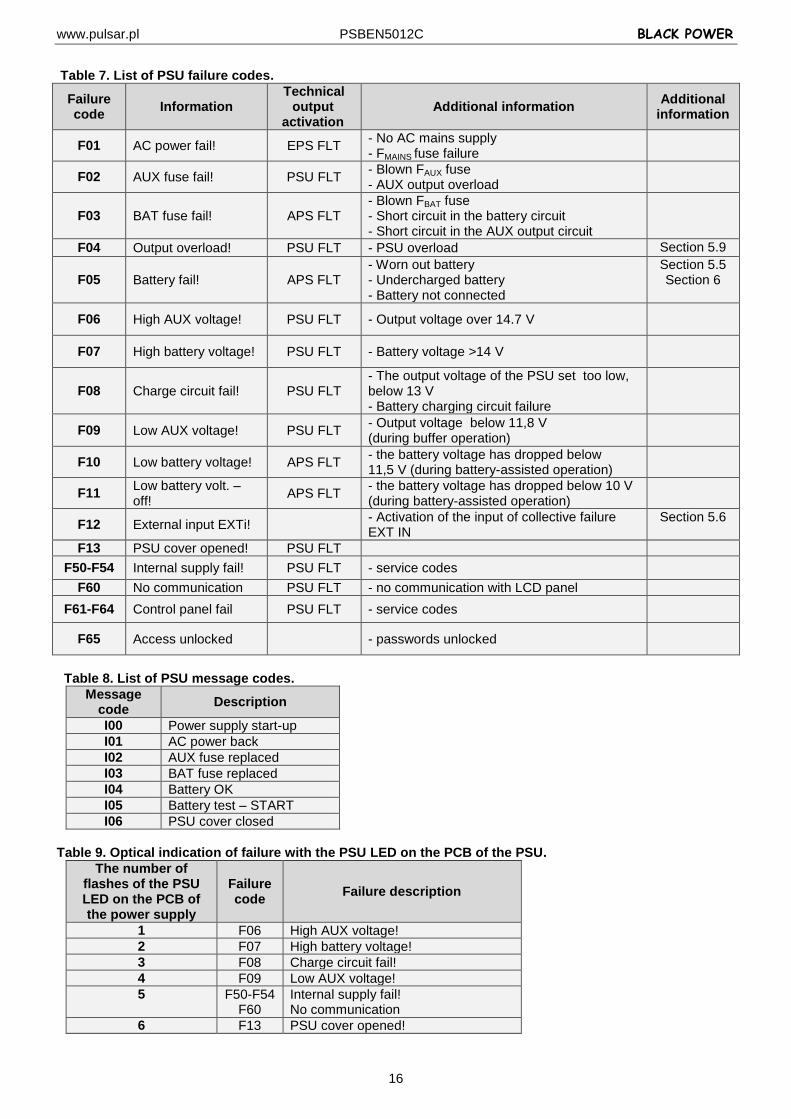
Table 7. List of PSU failure codes.
Failure code
Information Technical
output activation
Additional information Additional
information
F01 AC power fail! EPS FLT - No AC mains supply - FMAINS fuse failure
F02 AUX fuse fail! PSU FLT - Blown FAUX fuse - AUX output overload
F03 BAT fuse fail! APS FLT - Blown FBAT fuse - Short circuit in the battery circuit - Short circuit in the AUX output circuit
F04 Output overload! PSU FLT - PSU overload Section 5.9
F05 Battery fail! APS FLT - Worn out battery - Undercharged battery - Battery not connected
Section 5.5 Section 6
F06 High AUX voltage! PSU FLT - Output voltage over 14.7 V
F07 High battery voltage! PSU FLT - Battery voltage >14 V
F08 Charge circuit fail! PSU FLT - The output voltage of the PSU set too low, below 13 V - Battery charging circuit failure
F09 Low AUX voltage! PSU FLT - Output voltage below 11,8 V (during buffer operation)
F10 Low battery voltage! APS FLT - the battery voltage has dropped below 11,5 V (during battery-assisted operation)
F11 Low battery volt. – off!
APS FLT - the battery voltage has dropped below 10 V (during battery-assisted operation)
F12 External input EXTi! - Activation of the input of collective failure EXT IN
Section 5.6
F13 PSU cover opened! PSU FLT
F50-F54 Internal supply fail! PSU FLT - service codes
F60 No communication PSU FLT - no communication with LCD panel
F61-F64 Control panel fail PSU FLT - service codes
F65 Access unlocked - passwords unlocked
Table 8. List of PSU message codes.
Message code
Description
I00 Power supply start-up
I01 AC power back
I02 AUX fuse replaced
I03 BAT fuse replaced
I04 Battery OK
I05 Battery test – START
I06 PSU cover closed
Table 9. Optical indication of failure with the PSU LED on the PCB of the PSU.
The number of flashes of the PSU LED on the PCB of the power supply
Failure code
Failure description
1 F06 High AUX voltage!
2 F07 High battery voltage!
3 F08 Charge circuit fail!
4 F09 Low AUX voltage!
5 F50-F54 F60
Internal supply fail! No communication
6 F13 PSU cover opened!
www.pulsar.pl PSBEN5012C BLACK POWER
17
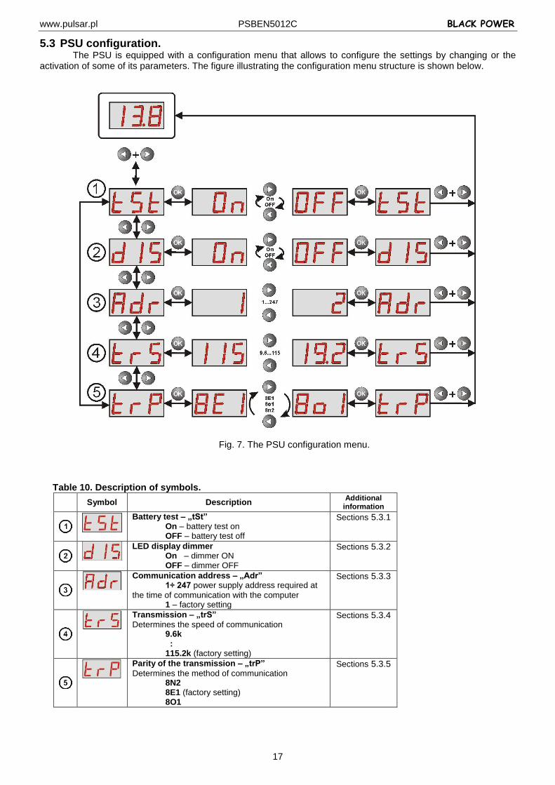
5.3 PSU configuration. The PSU is equipped with a configuration menu that allows to configure the settings by changing or the
activation of some of its parameters. The figure illustrating the configuration menu structure is shown below.
Fig. 7. The PSU configuration menu.
Table 10. Description of symbols.
Symbol Description Additional
information
Battery test – „tSt” On – battery test on OFF – battery test off
Sections 5.3.1
LED display dimmer On – dimmer ON OFF – dimmer OFF
Sections 5.3.2
Communication address – „Adr” 1÷ 247 power supply address required at
the time of communication with the computer 1 – factory setting
Sections 5.3.3
Transmission – „trS”
Determines the speed of communication 9.6k : 115.2k (factory setting)
Sections 5.3.4
Parity of the transmission – „trP”
Determines the method of communication 8N2 8E1 (factory setting) 8O1
Sections 5.3.5
www.pulsar.pl PSBEN5012C BLACK POWER
18
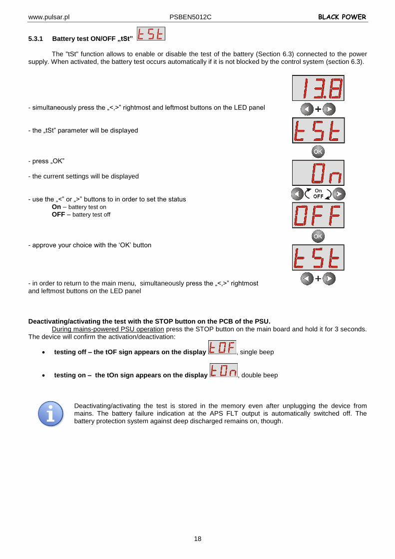
5.3.1 Battery test ON/OFF „tSt”
The "tSt" function allows to enable or disable the test of the battery (Section 6.3) connected to the power supply. When activated, the battery test occurs automatically if it is not blocked by the control system (section 6.3).
- simultaneously press the „<,>” rightmost and leftmost buttons on the LED panel - the „tSt” parameter will be displayed - press „OK” - the current settings will be displayed - use the „<” or „>” buttons to in order to set the status
On – battery test on OFF – battery test off
- approve your choice with the ‘OK’ button - in order to return to the main menu, simultaneously press the „<,>” rightmost and leftmost buttons on the LED panel Deactivating/activating the test with the STOP button on the PCB of the PSU.
During mains-powered PSU operation press the STOP button on the main board and hold it for 3 seconds. The device will confirm the activation/deactivation:
testing off – the tOF sign appears on the display , single beep
testing on – the tOn sign appears on the display , double beep
Deactivating/activating the test is stored in the memory even after unplugging the device from mains. The battery failure indication at the APS FLT output is automatically switched off. The battery protection system against deep discharged remains on, though.
www.pulsar.pl PSBEN5012C BLACK POWER
19
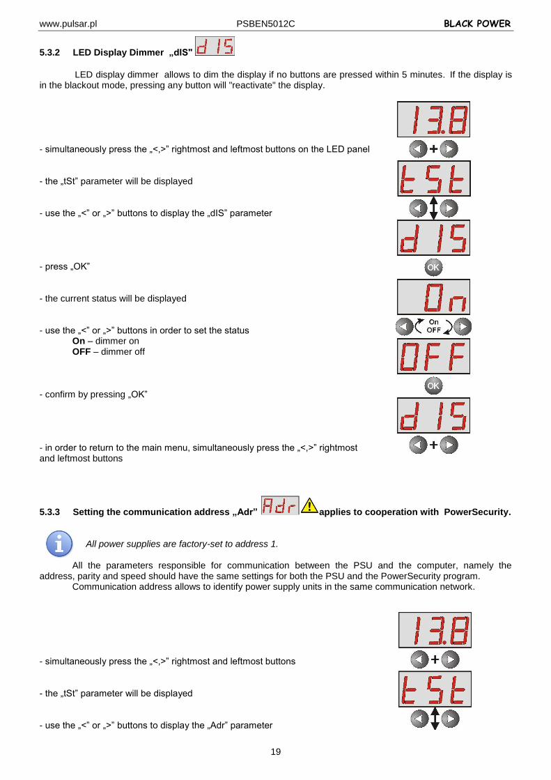
5.3.2 LED Display Dimmer „dIS"
LED display dimmer allows to dim the display if no buttons are pressed within 5 minutes.If the display is in the blackout mode, pressing any button will "reactivate" the display. - simultaneously press the „<,>” rightmost and leftmost buttons on the LED panel - the „tSt” parameter will be displayed - use the „<” or „>” buttons to display the „dIS” parameter - press „OK” - the current status will be displayed - use the „<” or „>” buttons in order to set the status
On – dimmer on OFF – dimmer off
- confirm by pressing „OK” - in order to return to the main menu, simultaneously press the „<,>” rightmost and leftmost buttons
5.3.3 Setting the communication address „Adr” applies to cooperation with PowerSecurity.
All power supplies are factory-set to address 1.
All the parameters responsible for communication between the PSU and the computer, namely the address, parity and speed should have the same settings for both the PSU and the PowerSecurity program.
Communication address allows to identify power supply units in the same communication network.
- simultaneously press the „<,>” rightmost and leftmost buttons - the „tSt” parameter will be displayed - use the „<” or „>” buttons to display the „Adr” parameter
www.pulsar.pl PSBEN5012C BLACK POWER
20
- press „OK” - the current address of the PSU will be displayed - use the „<” or „>” buttons in order to set the address
1÷ 247 – address of the PSU during the communication with the computer - confirm by pressing „OK” - in order to return to the main menu, simultaneously press the „<,>” rightmost and leftmost buttons
5.3.4 Setting the transmission speed „trS” applies to cooperation with PowerSecurity.
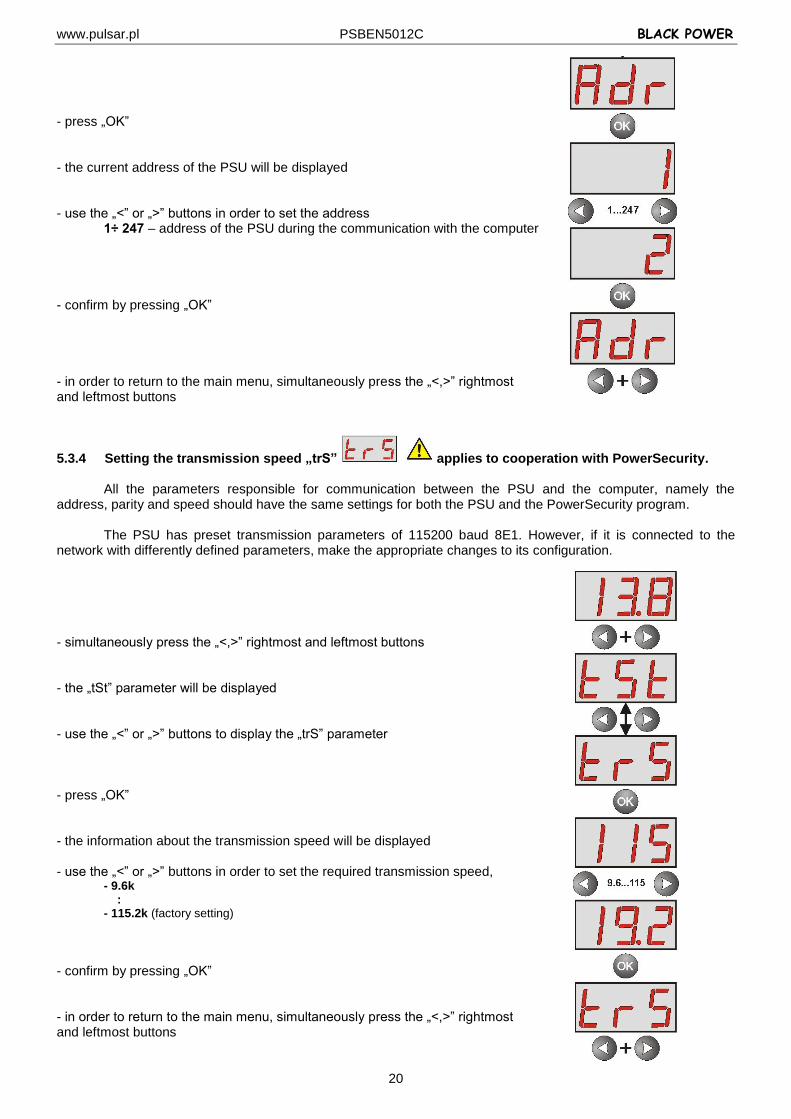
All the parameters responsible for communication between the PSU and the computer, namely the address, parity and speed should have the same settings for both the PSU and the PowerSecurity program.
The PSU has preset transmission parameters of 115200 baud 8E1. However, if it is connected to the
network with differently defined parameters, make the appropriate changes to its configuration. - simultaneously press the „<,>” rightmost and leftmost buttons - the „tSt” parameter will be displayed - use the „<” or „>” buttons to display the „trS” parameter - press „OK” - the information about the transmission speed will be displayed - use the „<” or „>” buttons in order to set the required transmission speed,
- 9.6k : - 115.2k (factory setting)
- confirm by pressing „OK” - in order to return to the main menu, simultaneously press the „<,>” rightmost and leftmost buttons
www.pulsar.pl PSBEN5012C BLACK POWER
21
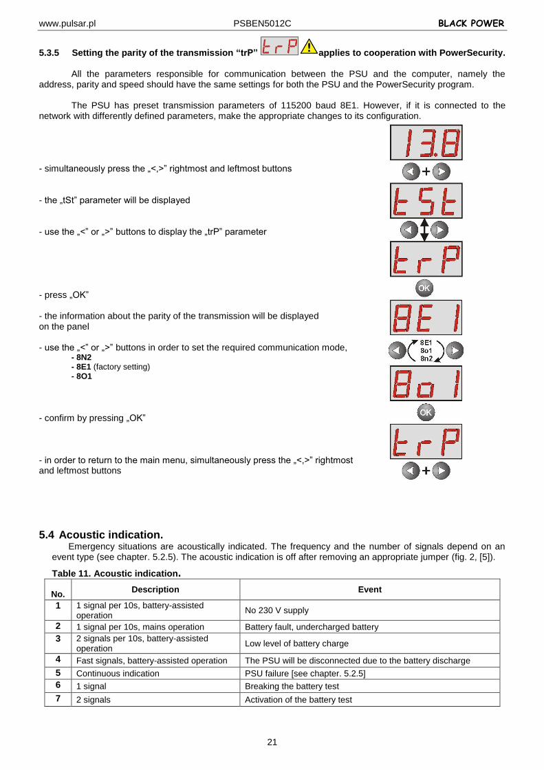
5.3.5 Setting the parity of the transmission “trP” applies to cooperation with PowerSecurity.
All the parameters responsible for communication between the PSU and the computer, namely the address, parity and speed should have the same settings for both the PSU and the PowerSecurity program.
The PSU has preset transmission parameters of 115200 baud 8E1. However, if it is connected to the
network with differently defined parameters, make the appropriate changes to its configuration. - simultaneously press the „<,>” rightmost and leftmost buttons - the „tSt” parameter will be displayed - use the „<” or „>” buttons to display the „trP” parameter - press „OK” - the information about the parity of the transmission will be displayed on the panel - use the „<” or „>” buttons in order to set the required communication mode,
- 8N2 - 8E1 (factory setting) - 8O1
- confirm by pressing „OK” - in order to return to the main menu, simultaneously press the „<,>” rightmost and leftmost buttons
5.4 Acoustic indication. Emergency situations are acoustically indicated. The frequency and the number of signals depend on an
event type (see chapter. 5.2.5). The acoustic indication is off after removing an appropriate jumper (fig. 2, [5]).
Table 11. Acoustic indication.
No. Description Event
1 1 signal per 10s, battery-assisted operation
No 230 V supply
2 1 signal per 10s, mains operation Battery fault, undercharged battery
3 2 signals per 10s, battery-assisted operation
Low level of battery charge
4 Fast signals, battery-assisted operation The PSU will be disconnected due to the battery discharge
5 Continuous indication PSU failure [see chapter. 5.2.5]
6 1 signal Breaking the battery test
7 2 signals Activation of the battery test
www.pulsar.pl PSBEN5012C BLACK POWER
22
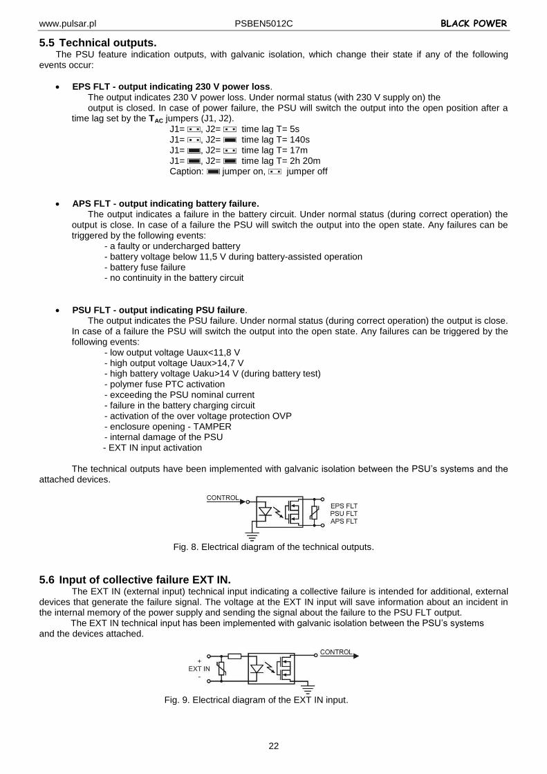
5.5 Technical outputs. The PSU feature indication outputs, with galvanic isolation, which change their state if any of the following
events occur:
EPS FLT - output indicating 230 V power loss. The output indicates 230 V power loss. Under normal status (with 230 V supply on) the output is closed. In case of power failure, the PSU will switch the output into the open position after a
time lag set by the TAC jumpers (J1, J2). J1= , J2= time lag T= 5s J1= , J2= time lag T= 140s J1= , J2= time lag T= 17m J1= , J2= time lag T= 2h 20m
Caption: jumper on, jumper off
APS FLT - output indicating battery failure. The output indicates a failure in the battery circuit. Under normal status (during correct operation) the
output is close. In case of a failure the PSU will switch the output into the open state. Any failures can be triggered by the following events:
- a faulty or undercharged battery - battery voltage below 11,5 V during battery-assisted operation
- battery fuse failure - no continuity in the battery circuit
PSU FLT - output indicating PSU failure. The output indicates the PSU failure. Under normal status (during correct operation) the output is close.
In case of a failure the PSU will switch the output into the open state. Any failures can be triggered by the following events:
- low output voltage Uaux<11,8 V - high output voltage Uaux>14,7 V - high battery voltage Uaku>14 V (during battery test) - polymer fuse PTC activation
- exceeding the PSU nominal current - failure in the battery charging circuit - activation of the over voltage protection OVP - enclosure opening - TAMPER - internal damage of the PSU
- EXT IN input activation
The technical outputs have been implemented with galvanic isolation between the PSU’s systems and the attached devices.
Fig. 8. Electrical diagram of the technical outputs.
5.6 Input of collective failure EXT IN. The EXT IN (external input) technical input indicating a collective failure is intended for additional, external
devices that generate the failure signal. The voltage at the EXT IN input will save information about an incident in the internal memory of the power supply and sending the signal about the failure to the PSU FLT output.
The EXT IN technical input has been implemented with galvanic isolation between the PSU’s systems and the devices attached.
Fig. 9. Electrical diagram of the EXT IN input.
www.pulsar.pl PSBEN5012C BLACK POWER
23
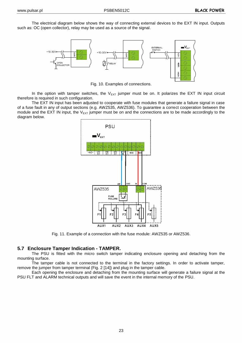
The electrical diagram below shows the way of connecting external devices to the EXT IN input. Outputs
such as: OC (open collector), relay may be used as a source of the signal.
Fig. 10. Examples of connections.
In the option with tamper switches, the VEXT jumper must be on. It polarizes the EXT IN input circuit
therefore is required in such configuration. The EXT IN input has been adjusted to cooperate with fuse modules that generate a failure signal in case
of a fuse fault in any of output sections (e.g. AWZ535, AWZ536). To guarantee a correct cooperation between the module and the EXT IN input, the VEXT jumper must be on and the connections are to be made accordingly to the diagram below.
Fig. 11. Example of a connection with the fuse module: AWZ535 or AWZ536.
5.7 Enclosure Tamper Indication - TAMPER. The PSU is fitted with the micro switch tamper indicating enclosure opening and detaching from the
mounting surface. The tamper cable is not connected to the terminal in the factory settings. In order to activate tamper,
remove the jumper from tamper terminal (Fig. 2 [14]) and plug in the tamper cable. Each opening the enclosure and detaching from the mounting surface will generate a failure signal at the
PSU FLT and ALARM technical outputs and will save the event in the internal memory of the PSU.

www.pulsar.pl PSBEN5012C BLACK POWER
24
5.8 Overvoltage protection of the PSU output OVP. In case of voltage exceeding 15,5 V±0.5 V at the switching regulator’s output, the system cuts off
the power at the outputs to protect the battery and the receivers from damage. The outputs will be battery-powered. The activation of the protection system is indicated by the OVP yellow LED on the PCB board, and the PSU FLT output.
5.9 PSU overload. The PSU is fitted with the LED OVL (overload) on the PCB and indicator on the LED panel,
informing about output overload. If the nominal current of the PSU is exceeded, the led turns on and the microprocessor starts a specially implemented procedure. Depending on time and overload level, microprocessor may disconnect the AUX output and switch into the battery-assisted operation. Restart will occur after 1 minute.
PSU overload is indicated by the PSU FLT technical output.
www.pulsar.pl PSBEN5012C BLACK POWER
25
6 Reserve power supply circuit. The power supply is equipped with intelligent circuits: charging and battery control circuit, whose main task is to monitor the condition of the battery and its connections in the circuit.
If the power supply driver detects a malfunction in the battery circuit, appropriate signaling and change in the APS FLT technical output take place.
6.1 Running the PSU from the battery. The PSU has been equipped with two buttons on the PCB board which enable running or disconnecting
the PSU during battery-assisted operation.
Running the PSU from the battery: press the START button on the main board and hold for 1s.
Disconnecting the PSU from the battery: press the STOP button on the main board and hold for 5s.
6.2 Deep discharge battery protection UVP. The PSU is equipped with the disconnection system and the discharged battery indication. If the voltage at
the battery terminals drops below 10 V±0.2 V will turn on the beep sound and disconnect the battery in the 15 seconds. Re-connecting the battery to the power supply occurs automatically upon the appearance of the ~230 V mains voltage. The protection mode is off when the PBAT jumper is removed.
Caution. Deactivating of the UVP function is not recommended since a deep discharge of the battery limits its capability of storing energy, lowers its capacity and shortens its durability.
6.3 Battery test. The PSU runs battery test every 5 minutes. During testing, the control unit of the PSU measures the
electrical parameters according to the implemented measuring method. A negative result occurs when the battery circuit continuity is interrupted or if the terminal voltage drops
below 12 V. The battery test can be activated manually (see section 5.3.1), from the menu of the power supply or by
pressing the STOP button, for example to test the replaced batteries. The PSU is protected against too frequent performing of the battery test, which could result in
undercharging. The protection involves blocking the ability to perform test for 60 seconds from the last activation.
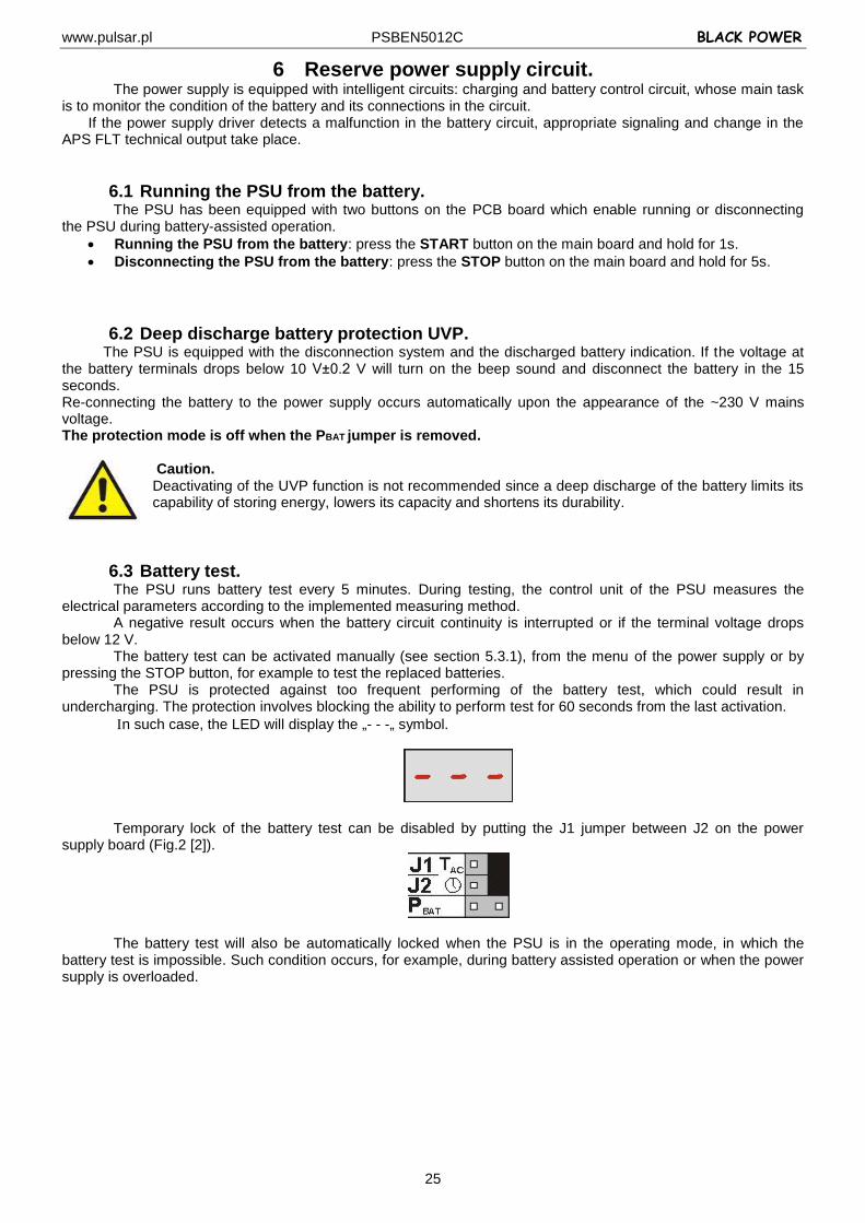
n such case, the LED will display the „- - -„ symbol.
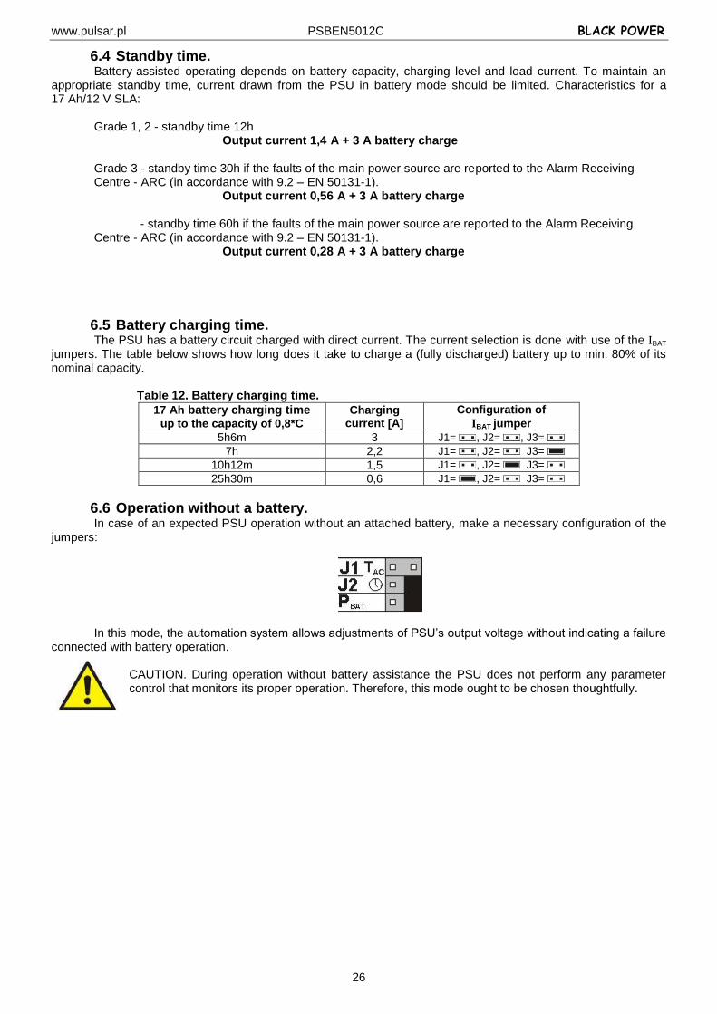
Temporary lock of the battery test can be disabled by putting the J1 jumper between J2 on the power supply board (Fig.2 [2]).
The battery test will also be automatically locked when the PSU is in the operating mode, in which the battery test is impossible. Such condition occurs, for example, during battery assisted operation or when the power supply is overloaded.
www.pulsar.pl PSBEN5012C BLACK POWER
26
6.4 Standby time. Battery-assisted operating depends on battery capacity, charging level and load current. To maintain an
appropriate standby time, current drawn from the PSU in battery mode should be limited. Characteristics for a 17 Ah/12 V SLA:
Grade 1, 2 - standby time 12h Output current 1,4 A + 3 A battery charge Grade 3 - standby time 30h if the faults of the main power source are reported to the Alarm Receiving Centre - ARC (in accordance with 9.2 – EN 50131-1). Output current 0,56 A + 3 A battery charge
- standby time 60h if the faults of the main power source are reported to the Alarm Receiving Centre - ARC (in accordance with 9.2 – EN 50131-1). Output current 0,28 A + 3 A battery charge
6.5 Battery charging time. The PSU has a battery circuit charged with direct current. The current selection is done with use of the IBAT
jumpers. The table below shows how long does it take to charge a (fully discharged) battery up to min. 80% of its nominal capacity.
Table 12. Battery charging time.
17 Ah battery charging time
up to the capacity of 0,8*C
Charging current [A]
Configuration of
IBAT jumper
5h6m 3 J1= , J2= , J3=
7h 2,2 J1= , J2= J3=
10h12m 1,5 J1= , J2= J3=
25h30m 0,6 J1= , J2= J3=
6.6 Operation without a battery. In case of an expected PSU operation without an attached battery, make a necessary configuration of the
jumpers:
In this mode, the automation system allows adjustments of PSU’s output voltage without indicating a failure connected with battery operation.
CAUTION. During operation without battery assistance the PSU does not perform any parameter control that monitors its proper operation. Therefore, this mode ought to be chosen thoughtfully.
www.pulsar.pl PSBEN5012C BLACK POWER
27
7. Remote monitoring (options: Ethernet, RS485). The PSU has been adjusted to operate in a system that requires a remote control of the parameters in a
monitoring centre. Transmitting data concerning PSU status is possible due to an additional, external communication module responsible for communication in Ethernet or RS485 standard.
Different connection topologies, presented later in this chapter, are only a part of possible communication schemes. More examples can be found in the manuals dedicated to individual interfaces.
When installing optional features in the power supply unit, power supply current consumption, used for the calculation of standby time, should be taken into account (see section. 6.4).
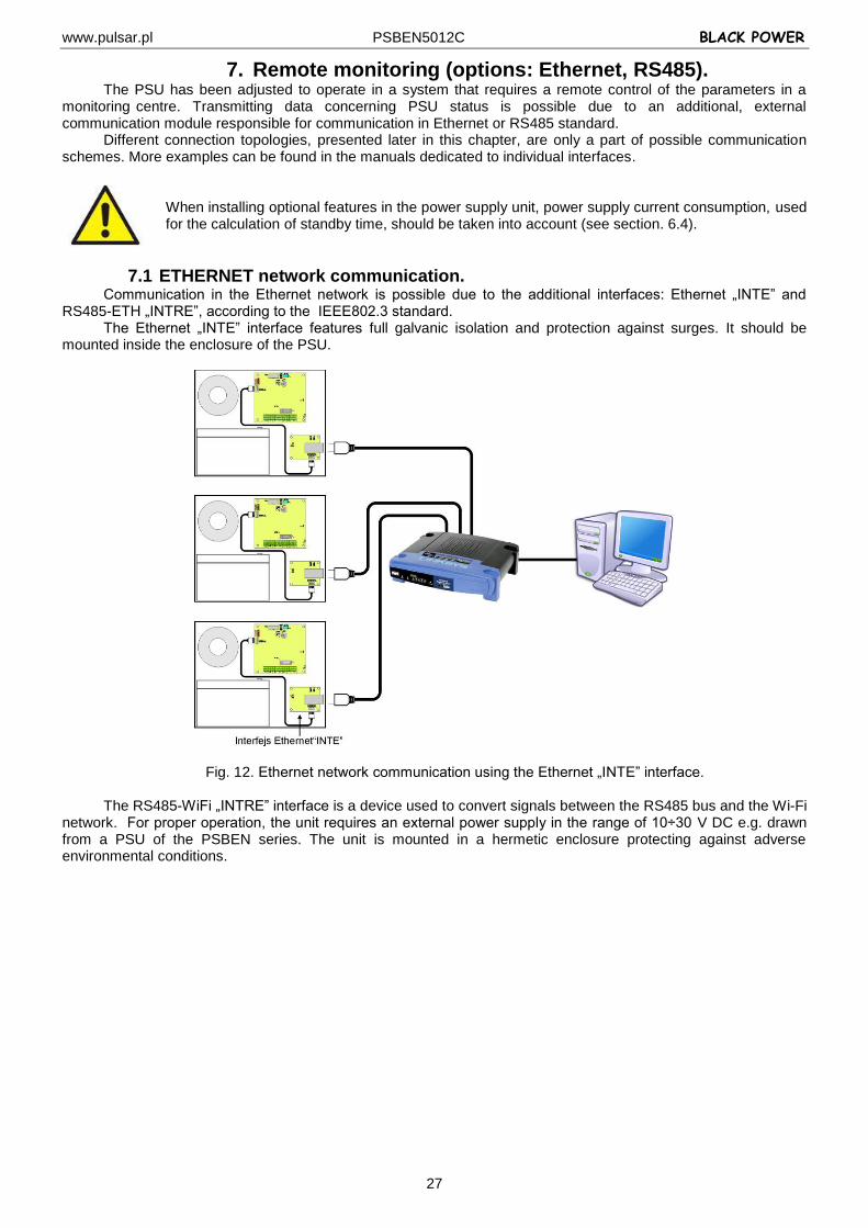
7.1 ETHERNET network communication. Communication in the Ethernet network is possible due to the additional interfaces: Ethernet „INTE” and
RS485-ETH „INTRE”, according to the IEEE802.3 standard. The Ethernet „INTE” interface features full galvanic isolation and protection against surges. It should be
mounted inside the enclosure of the PSU.
Fig. 12. Ethernet network communication using the Ethernet „INTE” interface.
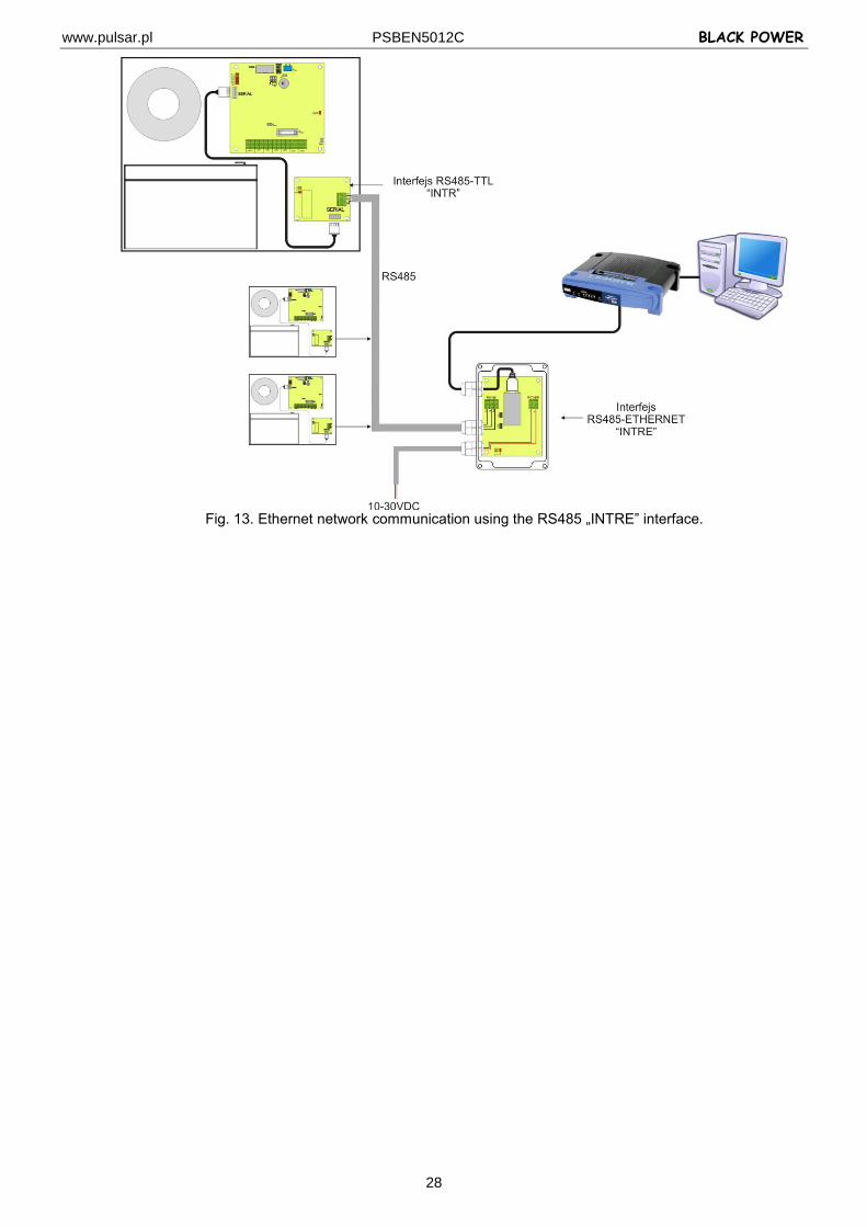
The RS485-WiFi „INTRE” interface is a device used to convert signals between the RS485 bus and the Wi-Fi network. For proper operation, the unit requires an external power supply in the range of 10÷30 V DC e.g. drawn from a PSU of the PSBEN series. The unit is mounted in a hermetic enclosure protecting against adverse environmental conditions.
www.pulsar.pl PSBEN5012C BLACK POWER
28
Fig. 13. Ethernet network communication using the RS485 „INTRE” interface.
www.pulsar.pl PSBEN5012C BLACK POWER
29
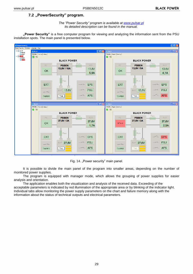
7.2 „PowerSecurity” program.
The ”Power Security” program is available at www.pulsar.pl Its detailed description can be found in the manual.
„Power Security” is a free computer program for viewing and analyzing the information sent from the PSU
installation spots. The main panel is presented below.
Fig. 14. „Power security” main panel.
It is possible to divide the main panel of the program into smaller areas, depending on the number of monitored power supplies.
The program is equipped with manager mode, which allows the grouping of power supplies for easier analysis and orientation.
The application enables both the visualization and analysis of the received data. Exceeding of the acceptable parameters is indicated by red illumination of the appropriate area or by blinking of the indicator light. Individual tabs allow monitoring the power supply parameters on the chart and failure memory along with the information about the status of technical outputs and electrical parameters.
www.pulsar.pl PSBEN5012C BLACK POWER
30
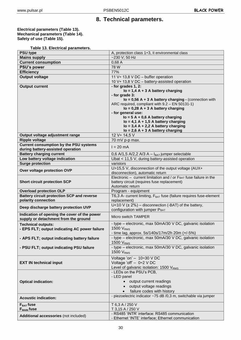
8. Technical parameters. Electrical parameters (Table 13). Mechanical parameters (Table 14). Safety of use (Table 15).
Table 13. Electrical parameters. PSU type A, protection class 1÷3, II environmental class
Mains supply ~230 V; 50 Hz
Current consumption 0,68 A
PSU’s power 78 W
Efficiency 77%
Output voltage 11 V÷ 13,8 V DC – buffer operation
10 V÷ 13,8 V DC – battery-assisted operation
Output current - for grades 1, 2: Io = 1,4 A + 3 A battery charging - for grade 3: Io = 0,56 A + 3 A battery charging - (connection with ARC required, compliant with 9.2 – EN 50131-1) Io = 0,28 A + 3 A battery charging - for general use: Io = 5 A + 0,6 A battery charging Io = 4,1 A + 1,5 A battery charging Io = 3,4 A + 2,2 A battery charging Io = 2,6 A + 3 A battery charging
Output voltage adjustment range 12 V÷ 14,5 V Ripple voltage 70 mV p-p max. Current consumption by the PSU systems during battery-assisted operation
I = 20 mA
Battery charging current 0,6 A/1,5 A/2,2 A/3 A – IBAT jumper selectable
Low battery voltage indication Ubat < 11,5 V, during battery-assisted operation Surge protection varistors
Over voltage protection OVP U>15,5 V, disconnection of the output voltage (AUX+
disconnection), automatic return
Short circuit protection SCP Electronic – current limitation and / or FBAT fuse failure in the battery circuit (requires fuse replacement) Automatic return
Overload protection OLP Program - equipment
Battery circuit protection SCP and reverse polarity connection
T6,3 A- current limiting, FBAT fuse (failure requires fuse-element
replacement)
Deep discharge battery protection UVP U<10 V (± 2%) – disconnection (-BAT) of the battery,
configuration with jumper PBAT Indication of opening the cover of the power supply or detachment from the ground
Micro switch TAMPER
Technical outputs:
- EPS FLT; output indicating AC power failure
- APS FLT; output indicating battery failure
- PSU FLT; output indicating PSU failure
- type – electronic, max 50mA/30 V DC, galvanic isolation 1500 VRMS - time lag, approx. 5s/140s/17m/2h 20m (+/-5%)
- type – electronic, max 50mA/30 V DC, galvanic isolation 1500 VRMS
- type – electronic, max 50mA/30 V DC, galvanic isolation 1500 VRMS
EXT IN technical input Voltage ’on’ – 10÷30 V DC Voltage ’off’ – 0÷2 V DC Level of galvanic isolation: 1500 VRMS
Optical indication:
- LEDs on the PSU’s PCB, - LED panel
output current readings
output voltage readings
failure codes with history
Acoustic indication: - piezoelectric indicator ~75 dB /0,3 m, switchable via jumper
FBAT fuse
FMAIN fuse T 6,3 A / 250 V T 3,15 A / 250 V
Additional accessories (not included) - RS485 ‘INTR’ interface: RS485 communication - Ethernet ‘INTE’ interface; Ethernet communication
www.pulsar.pl PSBEN5012C BLACK POWER
31
- RS485-Ethernet “INTRE’ interface; RS485-Ethernet communication
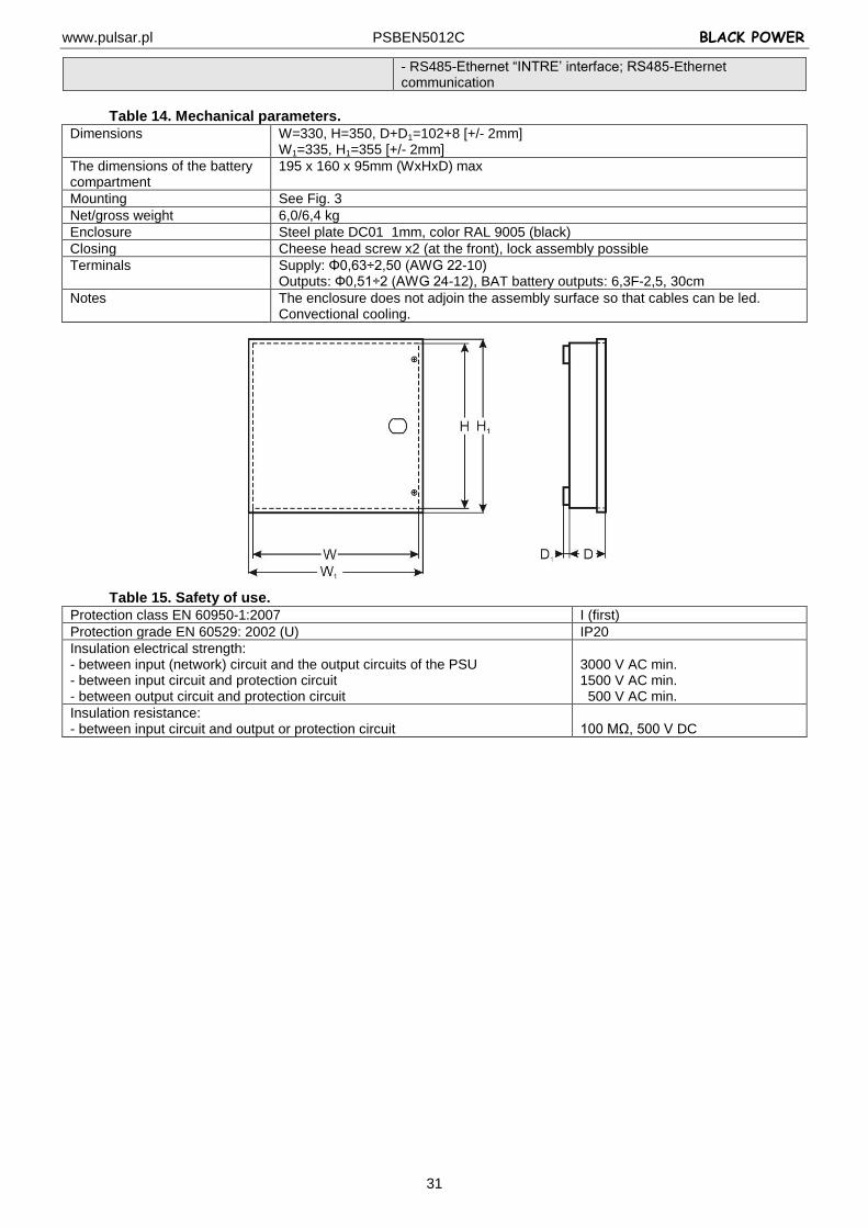
Table 14. Mechanical parameters.
Dimensions W=330, H=350, D+D1=102+8 [+/- 2mm] W1=335, H1=355 [+/- 2mm]
The dimensions of the battery compartment
195 x 160 x 95mm (WxHxD) max
Mounting See Fig. 3
Net/gross weight 6,0/6,4 kg
Enclosure Steel plate DC01 1mm, color RAL 9005 (black)
Closing Cheese head screw x2 (at the front), lock assembly possible
Terminals Supply: Φ0,63÷2,50 (AWG 22-10) Outputs: Ф0,51÷2 (AWG 24-12), BAT battery outputs: 6,3F-2,5, 30cm
Notes The enclosure does not adjoin the assembly surface so that cables can be led. Convectional cooling.
Table 15. Safety of use.
Protection class EN 60950-1:2007 I (first)
Protection grade EN 60529: 2002 (U) IP20
Insulation electrical strength: - between input (network) circuit and the output circuits of the PSU - between input circuit and protection circuit - between output circuit and protection circuit
3000 V AC min. 1500 V AC min. 500 V AC min.
Insulation resistance: - between input circuit and output or protection circuit
100 MΩ, 500 V DC
www.pulsar.pl PSBEN5012C BLACK POWER
32
9. Technical inspections and maintenance. Technical inspections and maintenance can be performed after disconnecting the power supply from the power network. The PSU does not require any specific maintenance; however, its interior should be cleaned with compressed air if it is used in dusty conditions. In case of fuse replacement, use only compatible replacement parts.
Technical inspections should be carried out not less frequently than once per year. During the inspection, check the batteries and run the battery test.
4 weeks after installation, re-tighten all screw connections, see Fig. 2 [9].
WEEE LABEL
According to the European Union WEEE Directive, waste electrical and electronic equipment should be disposed of separately from normal household waste. Waste electrical and electronic equipment
must not be disposed of with normal household waste.
CAUTION! The power supply unit is adapted for cooperation with the sealed lead-acid batteries (SLA). After the operation period they must not be thrown but recycled according to the applicable law
Pulsar sp. j. Siedlec 150, 32-744 Łapczyca, Poland
Phone (+48) 14-610-19-40, Fax (+48) 14-610-19-50 E-mail: [email protected], [email protected] http:// www.pulsar.pl, www.zasilacze.pl