Embed Size (px)
Citation preview

Product Data SheetPS-001482, Rev E
August 2015
Micro Motion® Compact Density MetersPeak performance precision density meter
Unparalleled real-world performance
Superior application performance via traceable calibrations, performed at combined pressure and temperature conditions
OIML R117-1 approved for MID conformance
Superior multi-variable I/O, meter health, and application capabilities
Flow rate indication (velocity) ensures sample integrity
Internal diagnostics for fast verification of meter health and installation
Application-specific factory configurations ensure fit-for-purpose operation
Installation flexibility and compatibility
Fluid, process and environmental effects are minimized to ensure superb measurement confidence
Supports multiple protocols for connection to DCS, PLC, and flow computers
Retrofit option available for Micro Motion 7835 and 7845 liquid density meters

2 www.micromotion.com
Compact Density Meter August 2015
Micro Motion® Compact Density MetersMicro Motion® compact density meters use the Micro Motion dual curved-tube meter technology to measure density. These meters use a multi-variable measurement system, designed for fiscal metering of high-value products such as crude oil, refined hydrocarbons, alcohol, and many aggressive process liquids.
Application configurationsAllows you to preselect an application-specific configuration for your meter from a wide range of options.
Integral transmitterSupports Time Period Signal (TPS), Analog (4–20 mA), HART, WirelessHART®, and Modbus RS-485 communications.
Meter diagnosticsEnsure measurement health through known density verification (KDV) and other meter and installation diagnostic capabilities.
Retrofit capabilitiesRetrofit option has the same face-to-face dimensions as the Micro Motion 7835 and 7845 density meters.
Thermal insulationA soft, weather-proof insulating jacket that is easily fitted to all CDM versions.
Accreditation and standardsAccredited calibrations and compliance with domestic and international standards.
STATUS
SCROLLSELECT
STATUS
SCROLL
SELECT
STATUS
SCROLLSELECT

www.micromotion.com 3
August 2015 Compact Density Meter
Operating principleCompact density meters use the Micro Motion dual curved-tube meter technology to measure density and flow rate (velocity).
Tube vibration Dual, parallel tubes vibrate at their natural frequency. The natural frequency changes with the density of the liquid
inside the tubes.
Density calibration Micro Motion transmitters accurately measure time period. Measured time periods are converted into density readings
using meter calibration coefficients. Multiple calibration points ensure optimum meter
performance.
Flow rate indication (velocity) Measuring the twist in the vibrating tubes gives an indication
of the liquid flow rate (velocity).

4 www.micromotion.com
Compact Density Meter August 2015
Performance specificationsDensity measurement
Temperature measurement
Flow rate indication (velocity)
SpecificationCDM100P (Peak performance precision density meter)
CDM100M (General purpose precision density meter)
Accuracy (liquid) ±0.1 kg/m3 (±0.0001 g/cm3) ±0.2 kg/m3 (±0.0002 g/cm3)
Repeatability ±0.02 kg/m3 (±0.00002 g/cm3) ±0.02 kg/m3 (±0.00002 g/cm3)
Operating density range 0–3000 kg/m3 (0–3 g/cm3) TPS transmitter version:0-1000 kg/m3 (0–1 g/cm3)
Analog/Discrete transmitter versions:0–3000 kg/m3 (0–3 g/cm3)
Calibration range 300–1300 kg/m3 (0.3–1.3 g/cm3) 300–1300 kg/m3 (0.3–1.3 g/cm3)
Process temperature effect (corrected)(1)
(1) Process temperature effect is the maximum measurement offset due to process fluid temperature changing away from the density calibration temperature.
±0.005 kg/m3 per °C ±0.278 kg/m3 per 100 °F
±0.015 kg/m3 per °C ±0.834 kg/m3 per 100 °F
Sensor maximum working pressure 248 bar (3600 psi) or flange limit 100 bar (1450 psi) or flange limit
Process pressure effect (corrected)(2)
(2) Process pressure effect is defined as the change in the sensor density sensitivity due to process pressure changing away from the calibration pressure. To determine the factory calibration pressure, refer to the calibration document shipped with the meter.
±0.003 kg/m3 per bar ±0.021 kg/m3 per 100 psi
±0.006 kg/m3 per bar ±0.042 kg/m3 per 100 psi
Specification Value
Operating temperature range –58 °F to +400 °F (–50 °C to +204 °C)
Integral temperature sensor Traceable calibration Technology: 100 Ω RTD Accuracy: BS1904 Class, DIN 43760 Class A
(±0.15 +0.002 x Temp °C)
Case temperature sensors(1)
(1) Case temperature sensors are used for environmental temperature effect correction in applications where the case temperature measurement does not need to be traceable and/or accredited. Where accreditation and measurement traceability are required, these sensors are used for diagnostics purposes only and do not perform any correction on the density measurement.
Technology: 3 x 100 Ω RTD Accuracy: BS1904 Class, DIN 43760 Class B
(±0.30 +0.005 x Temp °C)
Specification Value
Accuracy ±5% of reading with 10:1 turndown
Nominal flow rate (bidirectional) 13 m3/h
Nominal velocity (bidirectional) 10 m/sec (32.8 ft/sec)

www.micromotion.com 5
August 2015 Compact Density Meter
Case pressure
Transmitter specificationsAvailable transmitter versions
Local display
Specification Value
Maximum case working pressure 27 bar (389 psig)
Typical burst pressure (case) 195 bar (2824 psig)
Typical application Transmitter version(1)
Output channels
A B C
General purpose measurement DCS/PLC connection
Analog 4–20 mA + HART (passive)
4–20 mA (passive) Modbus/RS-485
Processor for remote-mount 2700 FOUNDATION fieldbus
transmitter
Disabled Disabled Modbus/RS-485
General purpose measurement with output switch
DCS/PLC connection
Discrete 4–20 mA + HART (passive)
Discrete output Modbus/RS-485
Fiscal/Custody Transfer Flow Computer connection
Time Period Signal (TPS) 4–20 mA + HART (passive)
Time Period Signal (TPS)
Modbus/RS-485
(1)For more information on the transmitter outputs and ordering codes, see the product ordering information.
Design Features
Physical Segmented two-line LCD screen. Can be rotated on transmitter, in 90-degree increments, for ease of viewing. Suitable for hazardous area operation. Optical switch controls for hazardous area configuration and display. Glass lens. Three-color LED indicates meter and alert status.
Functions View process variables. View and acknowledge alerts. Configure mA and RS-485 outputs. Supports Known Density Verification (KDV). Supports multiple languages.
6 www.micromotion.com
Compact Density Meter August 2015
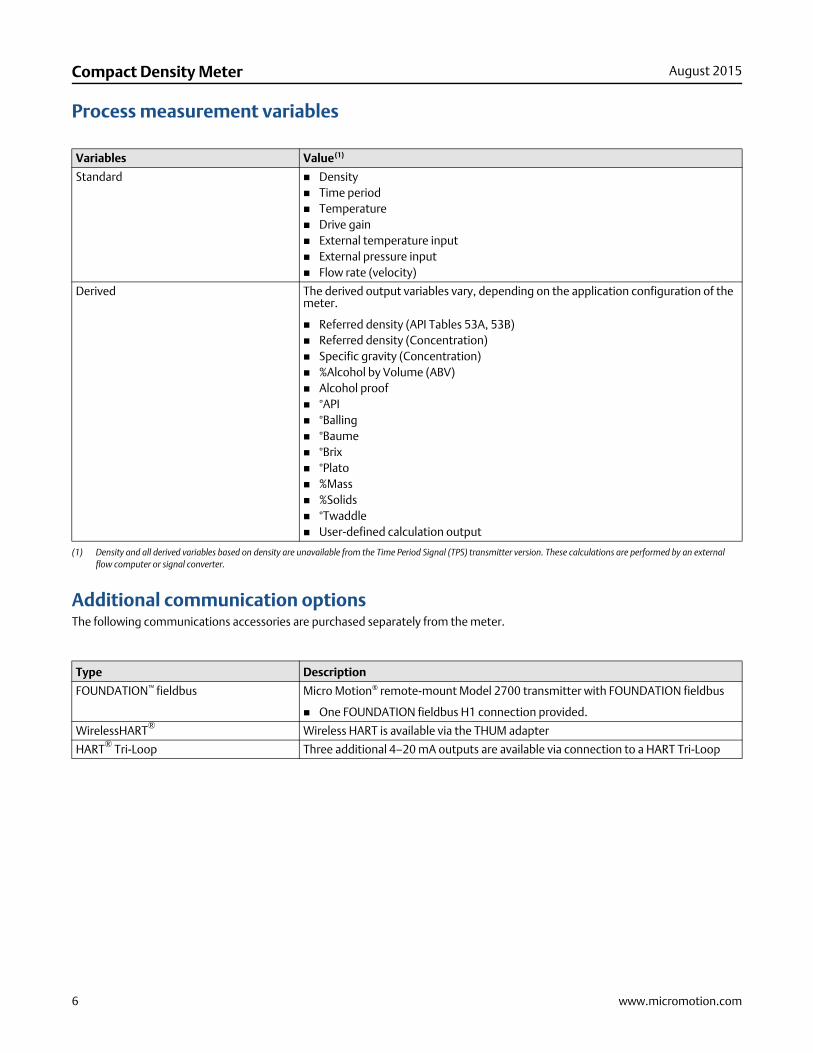
Process measurement variables
Additional communication optionsThe following communications accessories are purchased separately from the meter.
Variables Value(1)
(1) Density and all derived variables based on density are unavailable from the Time Period Signal (TPS) transmitter version. These calculations are performed by an external flow computer or signal converter.
Standard Density Time period Temperature Drive gain External temperature input External pressure input Flow rate (velocity)
Derived The derived output variables vary, depending on the application configuration of the meter.
Referred density (API Tables 53A, 53B) Referred density (Concentration) Specific gravity (Concentration) %Alcohol by Volume (ABV) Alcohol proof °API °Balling °Baume °Brix °Plato %Mass %Solids °Twaddle User-defined calculation output
Type Description
FOUNDATION™ fieldbus Micro Motion® remote-mount Model 2700 transmitter with FOUNDATION fieldbus
One FOUNDATION fieldbus H1 connection provided.
WirelessHART® Wireless HART is available via the THUM adapter
HART® Tri-Loop Three additional 4–20 mA outputs are available via connection to a HART Tri-Loop

www.micromotion.com 7
August 2015 Compact Density Meter
Hazardous area approvalsAmbient and process temperature limits are defined by temperature graphs for each meter and electronics interface option. Refer to the detailed approval specifications, including temperature graphs for all meter configurations, and safety instructions that can be found on the product page at the Micro Motion web site (at www.micromotion.com).
Environmental specifications
ATEX
Zone 1 Intrinsically safe With display (Analog, TPS, Discrete versions only)
II 2G Ex ib IIC T1-T4 Gb (–40 °C to +65 °C) II 2D Ex ib IIIC T(1) °C Db IP 66/67
(1) See the ATEX instructions shipped with the product for the maximum surface temperature (T) for dust.
Without display (All transmitter versions)
II 2G Ex ib IIC T1-T6 Gb (–40 °C to +65 °C) II 2D Ex ib IIIC T(1) °C Db IP 66/67
Zone 1 Flameproof Without display (All transmitter versions)
II 2G Ex d [ib] IIC T1-T6 Gb (–40 °C to +65 °C) II 2D Ex tb IIIC T(1) °C Db IP 66/67
CSA
Intrinsically safe With or without display (Analog, TPS, Discrete versions only)
Class I, Division 1, Groups A, B, C & D Class I, Division 2, Groups A, B, C & D Class II, Division 1, Groups E, F, & G
Explosion proof Without display (all transmitter versions)
Class I, Division 1, Groups C & D Class I, Division 2, Groups A, B, C & D Class II, Division 1, Groups E, F & G
IECEx
Zone 1 Intrinsically safe With display (Analog, TPS, Discrete versions only)
Ex ib IIC T1-T4 Gb (–40 °C to +65 °C)Without display (All transmitter versions)
Ex ib IIC T1-T6 Gb (–40 °C to +65 °C)
Zone 1 Flameproof Without display (All transmitter versions)
Ex d [ib] IIC T1-T6 Gb (–40 °C to +65 °C)
Specification Value
Ambient temperature limits –40 °C to +65 °C (–40 °F to +149°F)
Vibration limits Meets IEC 68.2.6, endurance sweep, 5 to 2000 Hz, 50 sweep cycles at 1.0 g
Ingress protection rating IP66/67, NEMA4
8 www.micromotion.com
Compact Density Meter August 2015
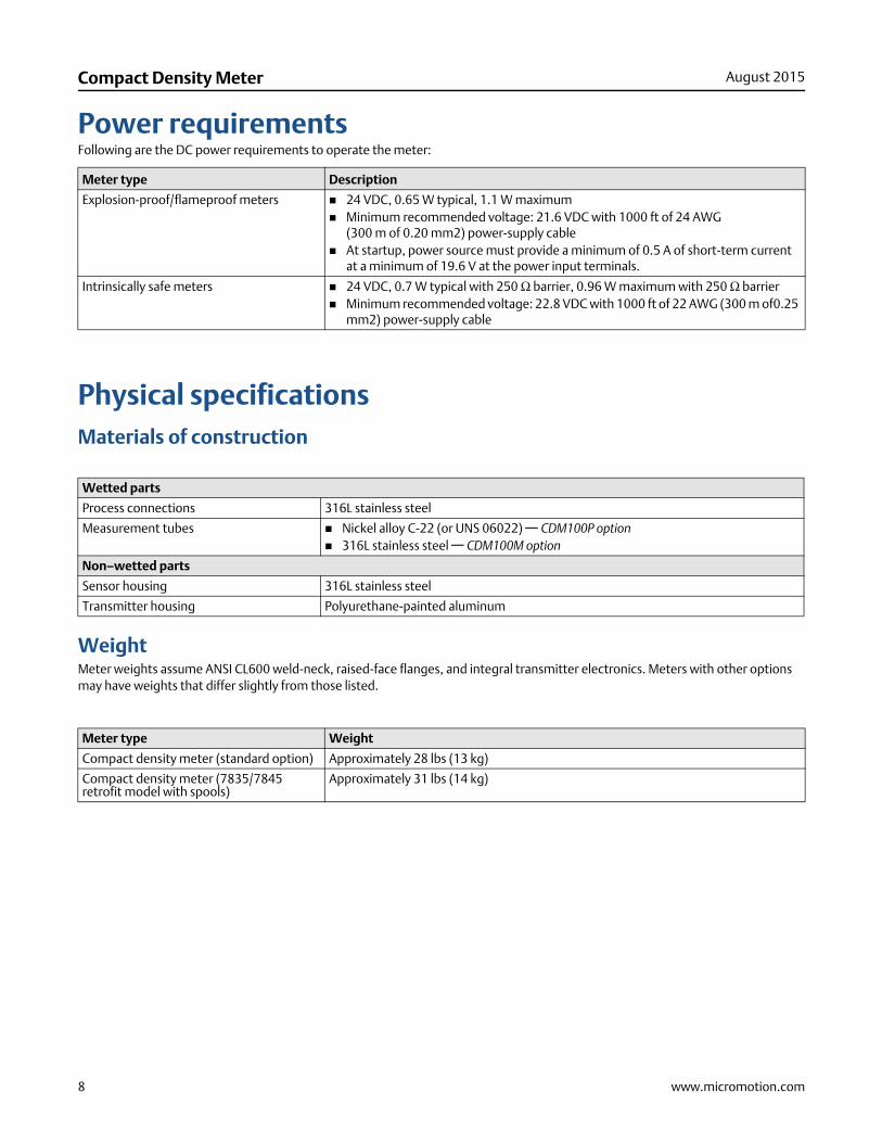
Power requirementsFollowing are the DC power requirements to operate the meter:
Physical specificationsMaterials of construction
WeightMeter weights assume ANSI CL600 weld-neck, raised-face flanges, and integral transmitter electronics. Meters with other options may have weights that differ slightly from those listed.
Meter type Description
Explosion-proof/flameproof meters 24 VDC, 0.65 W typical, 1.1 W maximum Minimum recommended voltage: 21.6 VDC with 1000 ft of 24 AWG
(300 m of 0.20 mm2) power-supply cable At startup, power source must provide a minimum of 0.5 A of short-term current
at a minimum of 19.6 V at the power input terminals.
Intrinsically safe meters 24 VDC, 0.7 W typical with 250 Ω barrier, 0.96 W maximum with 250 Ω barrier Minimum recommended voltage: 22.8 VDC with 1000 ft of 22 AWG (300 m of0.25
mm2) power-supply cable
Wetted parts
Process connections 316L stainless steel
Measurement tubes Nickel alloy C-22 (or UNS 06022) — CDM100P option 316L stainless steel — CDM100M option
Non–wetted parts
Sensor housing 316L stainless steel
Transmitter housing Polyurethane-painted aluminum
Meter type Weight
Compact density meter (standard option) Approximately 28 lbs (13 kg)
Compact density meter (7835/7845 retrofit model with spools)
Approximately 31 lbs (14 kg)

www.micromotion.com 9
August 2015 Compact Density Meter
DimensionsThese dimensional drawings are intended to provide a basic guideline for sizing and planning. Complete and detailed dimensional drawings can be found through the product drawings link in our online store (www.micromotion.com/onlinestore).
Depending on the flange connection, the face-to-face dimension may vary for the CDM standard option.
Compact density meter dimensions – standard option
Dimensions in inches(mm)
See table below for Dimension A
10 www.micromotion.com
Compact Density Meter August 2015
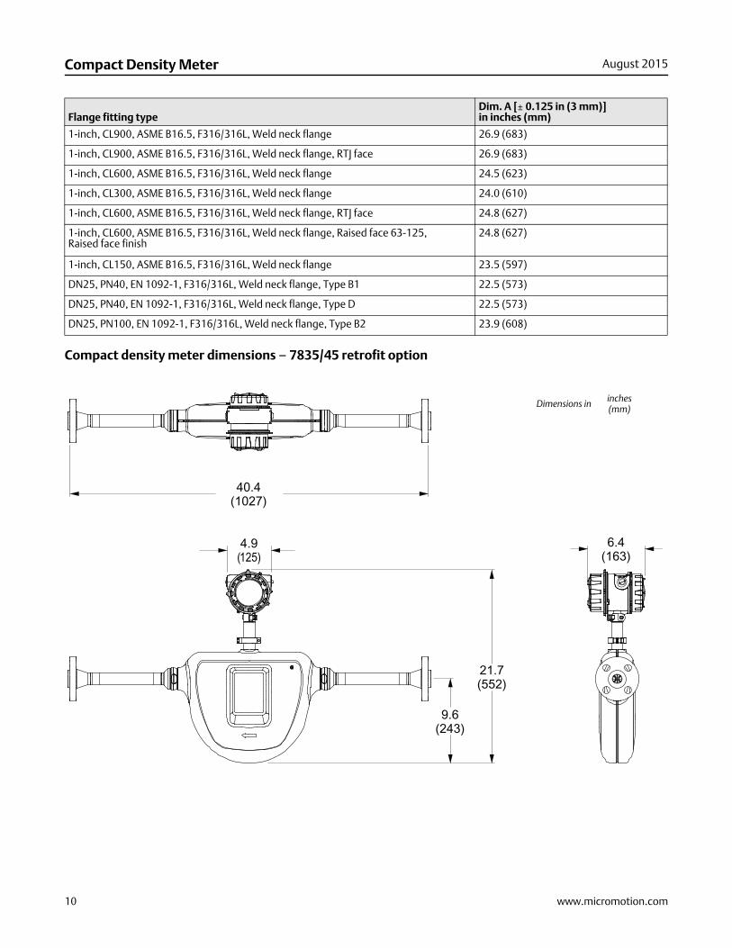
Compact density meter dimensions – 7835/45 retrofit option
Flange fitting typeDim. A [± 0.125 in (3 mm)] in inches (mm)
1-inch, CL900, ASME B16.5, F316/316L, Weld neck flange 26.9 (683)
1-inch, CL900, ASME B16.5, F316/316L, Weld neck flange, RTJ face 26.9 (683)
1-inch, CL600, ASME B16.5, F316/316L, Weld neck flange 24.5 (623)
1-inch, CL300, ASME B16.5, F316/316L, Weld neck flange 24.0 (610)
1-inch, CL600, ASME B16.5, F316/316L, Weld neck flange, RTJ face 24.8 (627)
1-inch, CL600, ASME B16.5, F316/316L, Weld neck flange, Raised face 63-125, Raised face finish
24.8 (627)
1-inch, CL150, ASME B16.5, F316/316L, Weld neck flange 23.5 (597)
DN25, PN40, EN 1092-1, F316/316L, Weld neck flange, Type B1 22.5 (573)
DN25, PN40, EN 1092-1, F316/316L, Weld neck flange, Type D 22.5 (573)
DN25, PN100, EN 1092-1, F316/316L, Weld neck flange, Type B2 23.9 (608)
Dimensions in inches(mm)

www.micromotion.com 11
August 2015 Compact Density Meter
Additional options for installation and configurationRequired barriers and isolators for hazardous area installationsWhen installing the meter in a hazardous area, safety barriers and galvanic isolators must be installed between the meter and the signal processing equipment. Micro Motion provides the required barriers and isolators for purchase according to the transmitter output type.
Safety barrier/galvanic isolator kits ordering informationThe following kits are available for purchase through Micro Motion. For more information on ordering these barriers, contact your local sales representative or Micro Motion Customer Support at [email protected].
ProLink® III software: a configuration and service toolProLink® III software is an easy-to-use interface that allows you to view key process variables and diagnostics data for your meter. For more information on ordering the software, contact your local sales representative or Micro Motion Customer Support at [email protected].
Model code Description Barrier/Isolator Output Notes
BARRIERSETAA Barrier set, including barriers for all intrinsically safe transmitter versions (CH B: mA, TPS, or DO)
MTL7728P+ mA + HART
MTL7728P+ mA / TPS / DO
MTL7761AC RS-485
MTL7728P+ Power
ISOLATORSETBB Isolator set, including isolators for intrinsically safe Analog version (CH B: mA)
MTL5541 mA + HART RS-485 barrier is not isolated.MTL5541 mA
MTL7761AC RS-485
MTL5523 Power
ISOLATORSETCC Isolator set, including isolators for intrinsically safe Time Period Signal (TPS)/Discrete versions (CH B: TPS or DO)
MTL5541 mA + HART RS-485 barrier is not isolated.MTL5532 TPS/DO
MTL7761AC RS-485
MTL5523 Power

12 www.micromotion.com
Compact Density Meter August 2015
Ordering informationPeak performance precision density meter (CDM100P)
Model Description
CDM100P Micro Motion compact density meter, 1‐inch (25mm) nickel alloy manifold and measurement tubes with stainless steel fittings
Code Process connection
A18 1-inch, CL900/1500, ASME B16.5, F316/316L, Weld neck flange
A25 1-inch, CL900/1500, ASME B16.5, F316/316L, Weld neck flange, RTJ Face
330 1-inch, CL600, ASME B16.5, F316/316L, Weld neck flange
329 1-inch, CL300, ASME B16.5, F316/316L, Weld neck flange
A24 1-inch, CL600, ASME B16.5, F316/316L, Weld neck flange, RTJ Face
A21 1-inch, CL600, ASME B16.5, F316/316L, Weld neck flange, Raised face 63-125, Raised face finish
179 DN25, PN40, EN 1092-1, F316/316L, Weld neck flange, Type B1
311 DN25, PN40, EN 1092-1, F316/316L, Weld neck flange, Type D
180 DN25, PN100, EN 1092-1, F316/316L, Weld neck flange, Type B2
999(1)
(1) Requires factory option X.
ETO process connection
Code Case option
M 316L stainless steel case
K 316L stainless steel case with purge fittings (one 1/2-inch NPT female)
C(1)
(1) Available only with process connection codes 329, 330, and A18.
7835/45 retrofit model with standard 316L stainless steel sensor case
D(1) 7835/45 retrofit model with purge fittings (1/2-inch NPT) 316L stainless steel sensor case
Code Transmitter output option
A(1) (2)
(1) Requires remote-mount Model 2700 transmitter with mounting option H- 4 wire connection option (power and communications).(2) With transmitter output options code A, all signal outputs on the integrally mounted transmitter are disabled, except for the Modbus/RS-485 communications which is used
for communication to the Model 2700 transmitter.
Integral processor for remote mount 2700 FOUNDATION fieldbus transmitter (Channels A and B inactive)
B Integral transmitter, Channel B = Time Period Signal, Channel A = mA + HART, Channel C = Modbus/RS-485
C Integral transmitter, Channel B = mA output, Channel A = mA + HART, Channel C = Modbus/RS-485
D Integral transmitter, Channel B = Discrete output, Channel A = mA + HART, Channel C = Modbus/RS-485
Code Display option
A No display
B(1) (2)
(1) Available only with approvals codes Z, B and E, 2 and M.(2) Not available with transmitter output option code B.
Two-line display (non-backlit)

www.micromotion.com 13
August 2015 Compact Density Meter
Code Approvals
For all transmitter output options
M Safe area - no hazardous area approval
Z ATEX – Intrinsically safe (zone 1)
B CSA (US and Canada) – Intrinsically safe Class 1 Div. 1 Groups B, C, D
E IECEx – Intrinsically safe (zone 1)
2 CSA (US and Canada) Class 1 Div. 2
For transmitter output options B, C, and D
A CSA (US and Canada) – Explosion-proof Class 1 Div. 1 Groups C, D (US and Canada)
F ATEX – Zone 1 flameproof
I IECEx – Zone 1 flameproof
Code Application configuration(1)
(1) When the transmitter output options code is B, C or D, the chosen application configuration code low and high limits are also programmed as the channel A mA output 4mA and 20mA points.
Available with all Transmitter output options
00 No Application configuration
95 Process temperature (4 mA = 0 °C, 20 mA = 200 °C)
96 Process temperature (4 mA = –50 °C, 20 mA = 200 °C)
97 Process temperature (4 mA = –50 °C, 20 mA = 150 °C)
98 Process temperature (4 mA = 0 °C, 20 mA = 100 °C)
XX(2)
(2) Requires factory option X.
ETO analog output configuration (customer data required)
Available with transmitter output options C and D
11 Degrees API (4 mA = 0°, 20 mA = 100°) (Process temperature = 0 °C to 60 °C)
12 Line Density (4 mA = 500 kg/m3, 20 mA = 1500 kg/m3) (Process temperature = –40 °C to +140 °C)
13 Base Density to API tables (metric) (4 mA = 500 kg/m3, 20 mA = 1500 kg/m3) (Process temperature = –40 °C to +140 °C)
21 % Alcohol (4 mA = 0%, 20 mA = 20%) (Process temperature = 0 °C to 40 °C)
22 % Alcohol (4 mA = 50%, 20 mA = 100%) (Process temperature = 40 °C to 70 °C)
23 % Alcohol (4 mA = 80%, 20 mA = 100%) (Process temperature = 50 °C to 90 °C)
24 Alcohol proof (4 mA = 100, 20 mA = 200) (Process temperature = 50 °C to 70 °C)
25 Alcohol proof (4 mA = 160, 20 mA = 200) (Process temperature = 50 °C to 90 °C)
26 % Methanol concentration (4 mA = 35%, 20 mA = 60%) (Process temperature = 0 °C to 40 °C)
27 % Ethylene Glycol concentration (4 mA = 10%, 20 mA = 50%) (Process temperature = –20 °C to 40 °C)
31 Brix sucrose (4 mA = 0°, 20 mA = 40°) (Process temperature = 0 °C to 100 °C)
32 Brix sucrose (4 mA = 30°, 20 mA = 80°) (Process temperature = 0 °C to 100 °C)
41 Balling (4 mA = 0°, 20 mA = 20°) (Process temperature = 0 °C to 100 °C)
51 % NaOH Concentration (4 mA = 0%, 20 mA = 20%) (Process temperature = 0 °C to 50 °C)
52 % H2SO4 Concentration (4 mA = 0%, 20 mA = 10%) (Process temperature = 0 °C to 38 °C)
53 % H2SO4 Concentration (4 mA = 75%, 20 mA = 94%) (Process temperature = 24 °C to 38 °C)
64 % HFCS – 42 (4 mA = 0%, 20 mA = 50%) (Process temperature = 0 °C to 100 °C)
65 % HFCS – 55 (4 mA = 0%, 20 mA = 50%) (Process temperature = 0 °C to 100 °C)
66 % HFCS – 90 (4 mA = 0%, 20 mA = 50%) (Process temperature = 0 °C to 100 °C)
71 Plato (4 mA = 0°, 20 mA = 30°) (Process temperature = 0 °C to 100 °C)

14 www.micromotion.com
Compact Density Meter August 2015
Code Language (manual and software)
Transmitter display language English
E English installation manual and English configuration manual
I Italian installation manual and English configuration manual
M Chinese installation manual and English configuration manual
R Russian installation manual and English configuration manual
Transmitter display language French
F French installation manual and English configuration manual
Transmitter display language German
G German installation manual and English configuration manual
Transmitter display language Spanish
S Spanish installation manual and English configuration manual
Code Sensor calibration options
A Standard [±0.1 kg/m3 (±0.0001 g/cm3) density accuracy]
M(1)
(1) MID (OIML R117) calibration option not available with transmitter output option code A.
MID evaluated component (OIML R117) - Requires installation with an approved power supply
Code Thermal insulation
Z No thermal insulation (For CDM thermally insulating jacket, order part number INSJKTCDM100)
Code Conduit connections
Z Standard 1/2-inch NPT fittings (no adapters)
B M20 stainless steel adapters
Code Factory options
Z Standard product
X ETO product
s

www.micromotion.com 15
August 2015 Compact Density Meter
Code Special tests and certificates, tests, calibrations, and certificates (all are optional)(1)
(1) Multiple test or certificate options can be selected.
Material Quality Examination Tests and Certificates (select any from this group)
MC Material Inspection Certificate 3.1 (Supplier Lot Traceability per EN 10204)
NC NACE Certificate 2.1 (MR0175 and MR0103)
Pressure Testing (select any from this group)
HT Hydrostatic Test Certificate 3.1
Radiographic Examination (select only one from this group)
RT X-Ray Package 3.1 (Process connection only; Radiographic Examination Certificate with digital image; Weld map; Radiographic Inspection NDE Qualification)
Dye Penetrant Examination (select only one from this group)
D1 Dye Penetrant Test Package 3.1 (Processor connection only; Liquid Dye Penetration NDE Qualification)
D2 Dye Penetrant Test Package 3.1 (Case only; Liquid Dye Penetration NDE Qualification)
Weld Examination
WP Weld Procedure Package (Weld Map, Weld Procedure Specification, Weld Procedure Qualification Record, Welder Performance Qualification)
Positive Material Testing (select only one from this group)
PM Positive Material Test Certificate 3.1 (without carbon content)
Sensor Completion Options (select any from this group)
WG Witness General
SP Special Packaging
Instrument Tagging
TG Instrument Tagging – customer information required (max. 24 characters)
16 www.micromotion.com
Compact Density Meter August 2015
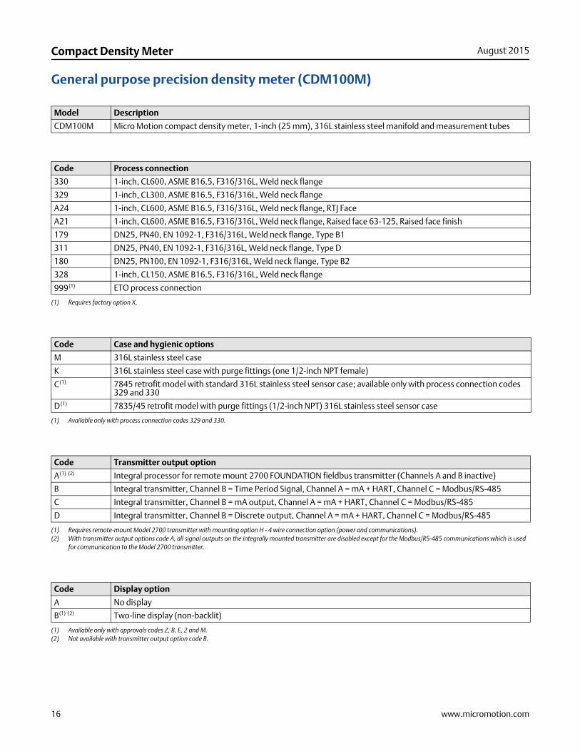
General purpose precision density meter (CDM100M)
Model Description
CDM100M Micro Motion compact density meter, 1-inch (25 mm), 316L stainless steel manifold and measurement tubes
Code Process connection
330 1-inch, CL600, ASME B16.5, F316/316L, Weld neck flange
329 1-inch, CL300, ASME B16.5, F316/316L, Weld neck flange
A24 1-inch, CL600, ASME B16.5, F316/316L, Weld neck flange, RTJ Face
A21 1-inch, CL600, ASME B16.5, F316/316L, Weld neck flange, Raised face 63-125, Raised face finish
179 DN25, PN40, EN 1092-1, F316/316L, Weld neck flange, Type B1
311 DN25, PN40, EN 1092-1, F316/316L, Weld neck flange, Type D
180 DN25, PN100, EN 1092-1, F316/316L, Weld neck flange, Type B2
328 1-inch, CL150, ASME B16.5, F316/316L, Weld neck flange
999(1)
(1) Requires factory option X.
ETO process connection
Code Case and hygienic options
M 316L stainless steel case
K 316L stainless steel case with purge fittings (one 1/2-inch NPT female)
C(1)
(1) Available only with process connection codes 329 and 330.
7845 retrofit model with standard 316L stainless steel sensor case; available only with process connection codes 329 and 330
D(1) 7835/45 retrofit model with purge fittings (1/2-inch NPT) 316L stainless steel sensor case
Code Transmitter output option
A(1) (2)
(1) Requires remote-mount Model 2700 transmitter with mounting option H - 4 wire connection option (power and communications).(2) With transmitter output options code A, all signal outputs on the integrally mounted transmitter are disabled except for the Modbus/RS-485 communications which is used
for communication to the Model 2700 transmitter.
Integral processor for remote mount 2700 FOUNDATION fieldbus transmitter (Channels A and B inactive)
B Integral transmitter, Channel B = Time Period Signal, Channel A = mA + HART, Channel C = Modbus/RS-485
C Integral transmitter, Channel B = mA output, Channel A = mA + HART, Channel C = Modbus/RS-485
D Integral transmitter, Channel B = Discrete output, Channel A = mA + HART, Channel C = Modbus/RS-485
Code Display option
A No display
B(1) (2)
(1) Available only with approvals codes Z, B, E, 2 and M.(2) Not available with transmitter output option code B.
Two-line display (non-backlit)

www.micromotion.com 17
August 2015 Compact Density Meter
Code Approvals
Available with all transmitter output options
M Safe area - no hazardous area approval
Z ATEX – Intrinsically safe (zone 1)
B CSA (US and Canada) – Intrinsically safe Class 1 Div. 1 Groups B, C, and D
E IECEx – Intrinsically safe (zone 1)
2 CSA (US and Canada) Class 1 Div. 2
Available with transmitter output option codes B, C, and D
A CSA (US and Canada) – Explosion-proof Class 1 Div. 1 Groups C & D (US and Canada)
F ATEX – Zone 1 flameproof
I IECEx – Zone 1 flameproof
Code Application configuration(1)
(1) When the transmitter output options code is B, C or D, the chosen application configuration code low and high limits are also programmed as the channel A mA output 4mA and 20mA points.
Available with all transmitter output options
00 No Application configuration
95 Process temperature (4 mA = 0 °C, 20 mA = 200 °C)
96 Process temperature (4 mA = –50 °C, 20 mA = 200 °C)
97 Process temperature (4 mA = –50 °C, 20 mA = 150 °C)
98 Process temperature (4 mA = 0 °C, 20 mA = 100 °C)
XX(2)
(2) Requires factory option X.
ETO analog output configuration (customer data required)
Available with transmitter output option codes C & D
11 Degrees API (4 mA = 0°, 20 mA = 100°) (Process temperature = 0 °C to 60 °C)
12 Line Density (4 mA = 500 kg/m3, 20 mA = 1500 kg/m3) (Process temperature = –40 °C to +140 °C)
13 Base Density to API tables (metric) (4 mA = 500 kg/m3, 20 mA = 1500 kg/m3)(Process temperature = –40 °C to +140 °C)
21 % Alcohol (4 mA = 0%, 20 mA = 20%) (Process temperature = 0 °C to 40 °C)
22 % Alcohol (4 mA = 50%, 20 mA = 100%) (Process temperature = 40 °C to 70 °C)
23 % Alcohol (4 mA = 80%, 20 mA = 100%) (Process temperature = 50 °C to 90 °C)
24 Alcohol proof (4 mA = 100, 20 mA = 200) (Process temperature = 50 °C to 70 °C)
25 Alcohol proof (4 mA = 160, 20 mA = 200) (Process temperature = 50 °C to 90 °C)
26 % Methanol concentration (4 mA = 35%, 20 mA = 60%) (Process temperature = 0 °C to 40 °C)
27 % Ethylene Glycol concentration (4 mA = 10%, 20 mA = 50%) (Process temperature = –20 °C to 40 °C)
31 Brix (4 mA = 0°, 20 mA = 40°) (Process temperature = 0 °C to 100 °C)
32 Brix (4 mA = 30°, 20 mA = 80°) (Process temperature = 0 °C to 100 °C)
41 Balling (4 mA = 0°, 20 mA = 20°) (Process temperature = 0 °C to 100 °C)
51 % NaOH Concentration (4 mA = 0%, 20 mA = 20%) (Process temperature = 0 °C to 50 °C)
52 % H2SO4 Concentration (4 mA = 0%, 20 mA = 10%) (Process temperature = 0 °C to 38 °C)
53 % H2SO4 Concentration (4 mA = 75%, 20 mA = 94%) (Process temperature = 24 °C to 38 °C)
54 % HN03 Concentration (4 mA = 0%, 20 mA = 40%) (Process temperature = 10 °C to 50 °C)
55 % KOH Concentration (4 mA = 0%, 20 mA = 40%) (Process temperature = 0 °C to 90 °C)
64 % HFCS – 42 (4 mA = 0%, 20 mA = 50%) (Process temperature = 0 °C to 100 °C)
65 % HFCS – 55 (4 mA = 0%, 20 mA = 50%) (Process temperature = 0 °C to 100 °C)
66 % HFCS – 90 (4 mA = 0%, 20 mA = 50%) (Process temperature = 0 °C to 100 °C)
71 Plato (4 mA = 0°, 20 mA = 30°) (Process temperature = 0 °C to 100 °C)

18 www.micromotion.com
Compact Density Meter August 2015
Code Language (manual and software)
Transmitter display language English
E English installation manual and English configuration manual
I Italian installation manual and English configuration manual
M Chinese installation manual and English configuration manual
R Russian installation manual and English configuration manual
Transmitter display language French
F French installation manual and English configuration manual
Transmitter display language German
G German installation manual and English configuration manual
Transmitter display language Spanish
S Spanish installation manual and English configuration manual
Code Sensor calibration options
A Standard [±0.2 kg/m3(±0.0002 g/cm3) density accuracy]
M(1)
(1) MID (OIML R117) calibration option not available with transmitter output options code A.
MID evaluated component (OIML R117) - Requires installation with an approved power supply
Code Thermal insulation
Z No thermal insulation (For CDM thermally insulating jacket, order part number INSJKTCDM100)
Code Conduit connections
Z Standard 1/2-inch NPT fittings (no adapters)
B M20 stainless steel adapters included
Code Factory options
Z Standard product
X ETO product

www.micromotion.com 19
August 2015 Compact Density Meter
Code Special tests and certificates, tests, calibrations, and services(1)
(1) Multiple add-ons may be selected.
Material Quality Examination Tests and Certificates (select any from this group)
MC Material Inspection Certificate 3.1 (Supplier Lot Traceability per EN 10204)
NC NACE Certificate 2.1 (MR0175 and MR0103)
Pressure Testing (select any from this group)
HT Hydrostatic Test Certificate 3.1
Radiographic Examination (select only one from this group)
RT X-Ray Package 3.1 (Process connection only; Radiographic Examination Certificate with digital image; Weld map; Radiographic Inspection NDE Qualification)
Dye Penetrant Examination (select only one from this group)
D1 Dye Penetrant Test Package 3.1 (Process connection only; Liquid Dye Penetration NDE Qualification)
D2 Dye Penetrant Test Package 3.1 (Case only; Liquid Dye Penetration NDE Qualification)
Weld Examination
WP Weld Procedure Package (Weld Map, Weld Procedure Specification, Weld Procedure Qualification Record, Welder Performance Qualification)
Positive Material Testing (select only one from this group)
PM Positive Material Test Certificate 3.1 (without carbon content)
PC Positive Material Test Certificate 3.1 (including carbon content)
Sensor Completion Options (select any from this group)
WG Witness General
SP Special Packaging
Instrument Tagging
TG Instrument Tagging – customer information required (max. 24 characters)

Compact Density MeterPS-001482, Rev E
Product Data SheetAugust 2015
7070 Winchester CircleBoulder, Colorado USA 80301www.MicroMotion.comwww.Rosemount.comI: +1 800 522 6277T: +1 (303) 527 5200F: +1 (303) 530 8459
MexicoArgentinaBrazilVenezuela
T: 52 55 5809 5300T: 54 11 4837 7000T: 55 15 3413 8000T: 58 26 1300 8100
Emerson Process ManagementAmericas
Central & Eastern EuropeDubaiAbu DhabiFranceGermanyItalyThe NetherlandsBelgiumSpainU.K.Russia/CIS
T: +41 41 7686 111 T: +971 4 811 8100T: +971 2 697 2000T: 0800 917 901T: 0800 182 5347T: 8008 77334T: +31 T: +32 2 716 77 11T: +34 913 586 000T: 0870 240 1978T: +7 495 981 9811
Emerson Process ManagementEurope/Middle East
AustraliaChinaIndiaJapanSouth KoreaSingapore
T: (61) 3 9721 0200T: (86) 21 2892 9000T: (91) 22 6662 0566T: (81) 3 5769 6803T: (82) 2 3438 4600T: (65) 6 777 8211
Emerson Process ManagementAsia Pacific
© 201 Micro Motion, Inc. All rights reserved.
The Emerson logo is a trademark and service mark of Emerson Electric Co. Micro Motion, ELITE, ProLink, MVD and MVD Direct Connect marks are marks of one of the Emerson Process Management family of companies. All other marks are property of their respective owners. Micro MotionSupplies this publication for informational purposes only. While every effort has been made to ensure accuracy, this publication is not intendedto make performance claims or process recommendations. Micro Motion does not warrant, guarantee, or assume any legal liability for theaccuracy, completeness, timeliness, reliability, or usefulness of any information, product, or process described herein. We reserve the right to modify or improve the designs or specifications of our products at any time wihout notice. For actual product information and recommendations, please contact your local Micro Motion representative.