Embed Size (px)
Citation preview
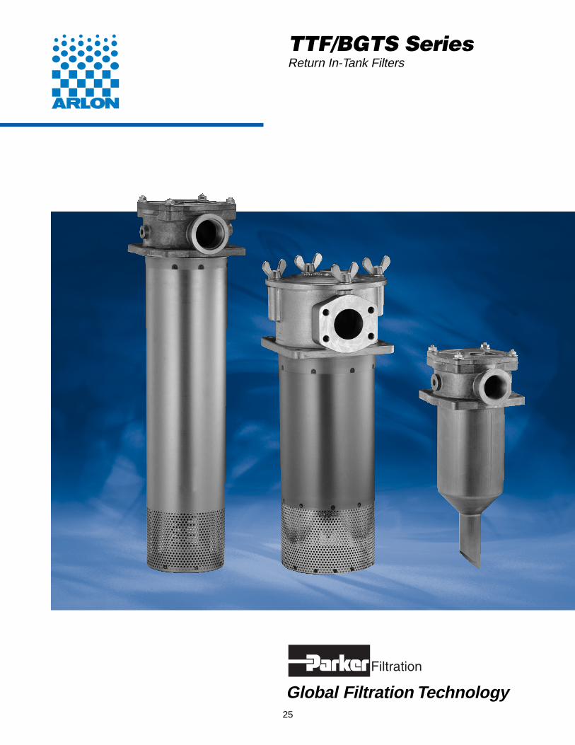
TTF/BGTS SeriesReturn In-Tank Filters
Global Filtration Technology25
Return In-Tank FiltersTTF/BGTS Series
Parker Hannifin CorporationHydraulic Filter DivisionMetamora, OH
Specifications
Housing Data:Material:
Head – Aluminum AlloyDiffusor – SteelInternals– Carbon Steel and AluminumSeals – Nitrile (Standard), FKM
Pressure Rating:Static – 150 psi (10.3 bar)
Temperature Range:Operating -40°F to +250°F(-40°C to +120°C)
26
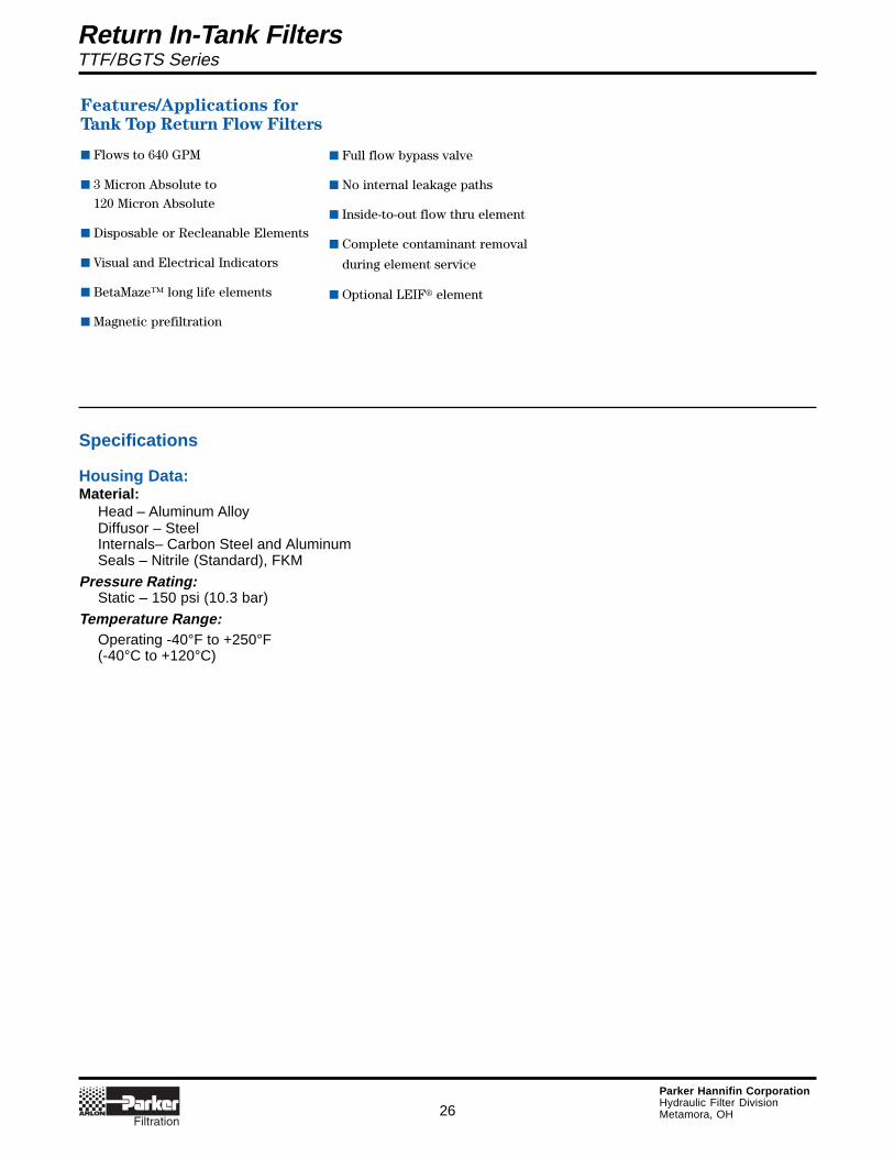
Features/Applications for
Tank Top Return Flow Filters
■ Flows to 640 GPM
■ 3 Micron Absolute to
120 Micron Absolute
■ Disposable or Recleanable Elements
■ Visual and Electrical Indicators
■ BetaMaze™ long life elements
■ Magnetic prefiltration
■ Full flow bypass valve
■ No internal leakage paths
■ Inside-to-out flow thru element
■ Complete contaminant removal
during element service
■ Optional LEIF® element
Return In-Tank FiltersTTF/BGTS Series
Parker Hannifin CorporationHydraulic Filter DivisionMetamora, OH
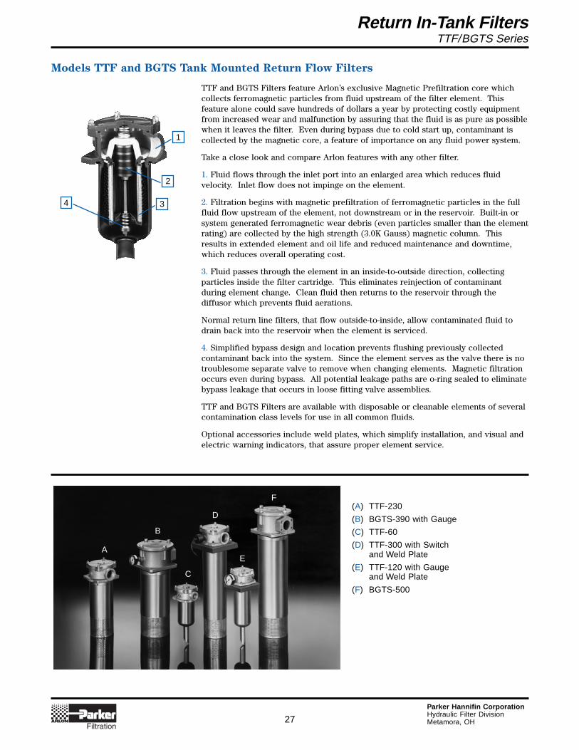
Models TTF and BGTS Tank Mounted Return Flow Filters
TTF and BGTS Filters feature Arlon’s exclusive Magnetic Prefiltration core whichcollects ferromagnetic particles from fluid upstream of the filter element. Thisfeature alone could save hundreds of dollars a year by protecting costly equipmentfrom increased wear and malfunction by assuring that the fluid is as pure as possiblewhen it leaves the filter. Even during bypass due to cold start up, contaminant iscollected by the magnetic core, a feature of importance on any fluid power system.
Take a close look and compare Arlon features with any other filter.
1. Fluid flows through the inlet port into an enlarged area which reduces fluidvelocity. Inlet flow does not impinge on the element.
2. Filtration begins with magnetic prefiltration of ferromagnetic particles in the fullfluid flow upstream of the element, not downstream or in the reservoir. Built-in orsystem generated ferromagnetic wear debris (even particles smaller than the elementrating) are collected by the high strength (3.0K Gauss) magnetic column. Thisresults in extended element and oil life and reduced maintenance and downtime,which reduces overall operating cost.
3. Fluid passes through the element in an inside-to-outside direction, collectingparticles inside the filter cartridge. This eliminates reinjection of contaminantduring element change. Clean fluid then returns to the reservoir through thediffusor which prevents fluid aerations.
Normal return line filters, that flow outside-to-inside, allow contaminated fluid todrain back into the reservoir when the element is serviced.
4. Simplified bypass design and location prevents flushing previously collectedcontaminant back into the system. Since the element serves as the valve there is notroublesome separate valve to remove when changing elements. Magnetic filtrationoccurs even during bypass. All potential leakage paths are o-ring sealed to eliminatebypass leakage that occurs in loose fitting valve assemblies.
TTF and BGTS Filters are available with disposable or cleanable elements of severalcontamination class levels for use in all common fluids.
Optional accessories include weld plates, which simplify installation, and visual andelectric warning indicators, that assure proper element service.
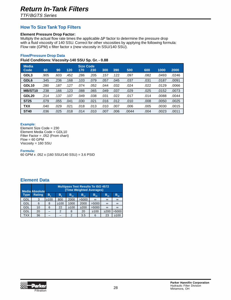
(A) TTF-230
(B) BGTS-390 with Gauge
(C) TTF-60
(D) TTF-300 with Switchand Weld Plate
(E) TTF-120 with Gaugeand Weld Plate
(F) BGTS-500
27
4
1
2
3
A
B
C
D
E
F
Return In-Tank FiltersTTF/BGTS Series
Parker Hannifin CorporationHydraulic Filter DivisionMetamora, OH
Example:Element Size Code = 230Element Media Code = GDL10Filter Factor = .052 (From chart)Flow = 60 GPMViscosity = 160 SSU
Formula:60 GPM x .052 x (160 SSU/140 SSU) = 3.6 PSID
Media Size CodeCode 60 90 120 170 230 300 390 500 600 1000 2000
GDL3 .905 .603 .452 .286 .205 .157 .122 .097 .082 .0493 .0246
GDL6 .345 .236 .168 .103 .079 .057 .045 .037 .031 .0187 .0091
GDL10 .280 .187 .127 .074 .052 .044 .032 .024 .022 .0129 .0066
MB/ST10 .238 .166 .123 .088 .065 .049 .037 .029 .025 .0152 .0073
GDL20 .214 .137 .107 .049 .038 .031 .022 .017 .014 .0088 .0044
ST25 .079 .055 .041 .030 .021 .016 .012 .010 .008 .0050 .0025
TXX .040 .029 .021 .018 .013 .010 .007 .006 .005 .0030 .0015
ST40 .036 .025 .018 .014 .010 .007 .006 .0044 .004 .0023 .0011
How To Size Tank Top Filters
Element Pressure Drop Factor:Multiply the actual flow rate times the applicable ∆P factor to determine the pressure dropwith a fluid viscosity of 140 SSU. Correct for other viscosities by applying the following formula:Flow rate (GPM) x filter factor x (new viscosity in SSU/140 SSU).
Flow/Pressure Drop DataFluid Conditions: Viscosity-140 SSU Sp. Gr. - 0.88
Multipass Test Results To ISO 4572
Media Absolute (Time Weighted Averages)
Type Rating B3 B6 B10 B12 B20 B25 B36
GDL 3 ≥100 800 2000 >5000 ∞ ∞ ∞GDL 6 8 ≥100 1000 2000 >5000 ∞ ∞GDL 10 6 22 ≥100 ≥200 >5000 ∞ ∞GDL 20 – 2 8 20 ≥100 ≥200 >5000TXX 36 – – 2 3.5 6 23 ≥100
28
Element Data
Return In-Tank FiltersTTF/BGTS Series
Parker Hannifin CorporationHydraulic Filter DivisionMetamora, OH
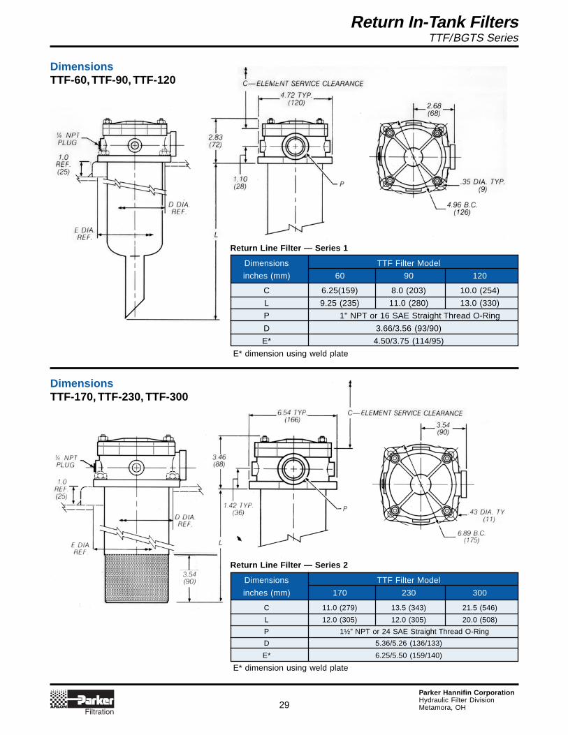
DimensionsTTF-60, TTF-90, TTF-120
DimensionsTTF-170, TTF-230, TTF-300
Dimensions TTF Filter Model
inches (mm) 60 90 120
C 6.25(159) 8.0 (203) 10.0 (254)
L 9.25 (235) 11.0 (280) 13.0 (330)
P 1" NPT or 16 SAE Straight Thread O-Ring
D 3.66/3.56 (93/90)
E* 4.50/3.75 (114/95)
E* dimension using weld plate
Return Line Filter — Series 1
Dimensions TTF Filter Model
inches (mm) 170 230 300
C 11.0 (279) 13.5 (343) 21.5 (546)
L 12.0 (305) 12.0 (305) 20.0 (508)
P 1½” NPT or 24 SAE Straight Thread O-Ring
D 5.36/5.26 (136/133)
E* 6.25/5.50 (159/140)
E* dimension using weld plate
Return Line Filter — Series 2
29
Return In-Tank FiltersTTF/BGTS Series
Parker Hannifin CorporationHydraulic Filter DivisionMetamora, OH
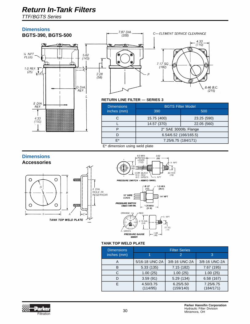
DimensionsBGTS-390, BGTS-500
DimensionsAccessories
Dimensions BGTS Filter Modelinches (mm) 390 500
C 15.75 (400) 23.25 (590)
L 14.57 (370) 22.05 (560)
P 2" SAE 3000lb. Flange
D 6.54/6.52 (166/165.5)
E* 7.25/6.75 (184/171)
E* dimension using weld plate
RETURN LINE FILTER — SERIES 3
Dimensions Filter Seriesinches (mm) 1 2 3
A 5/16-18 UNC-2A 3/8-16 UNC-2A 3/8-16 UNC-2A
B 5.33 (135) 7.15 (182) 7.67 (195)
C 1.00 (25) 1.00 (25) 1.00 (25)
D 3.59 (91) 5.29 (134) 6.58 (167)
E 4.50/3.75 6.25/5.50 7.25/6.75(114/95) (159/140) (184/171)
TANK TOP WELD PLATE
30
Return In-Tank FiltersTTF/BGTS Series
Parker Hannifin CorporationHydraulic Filter DivisionMetamora, OH
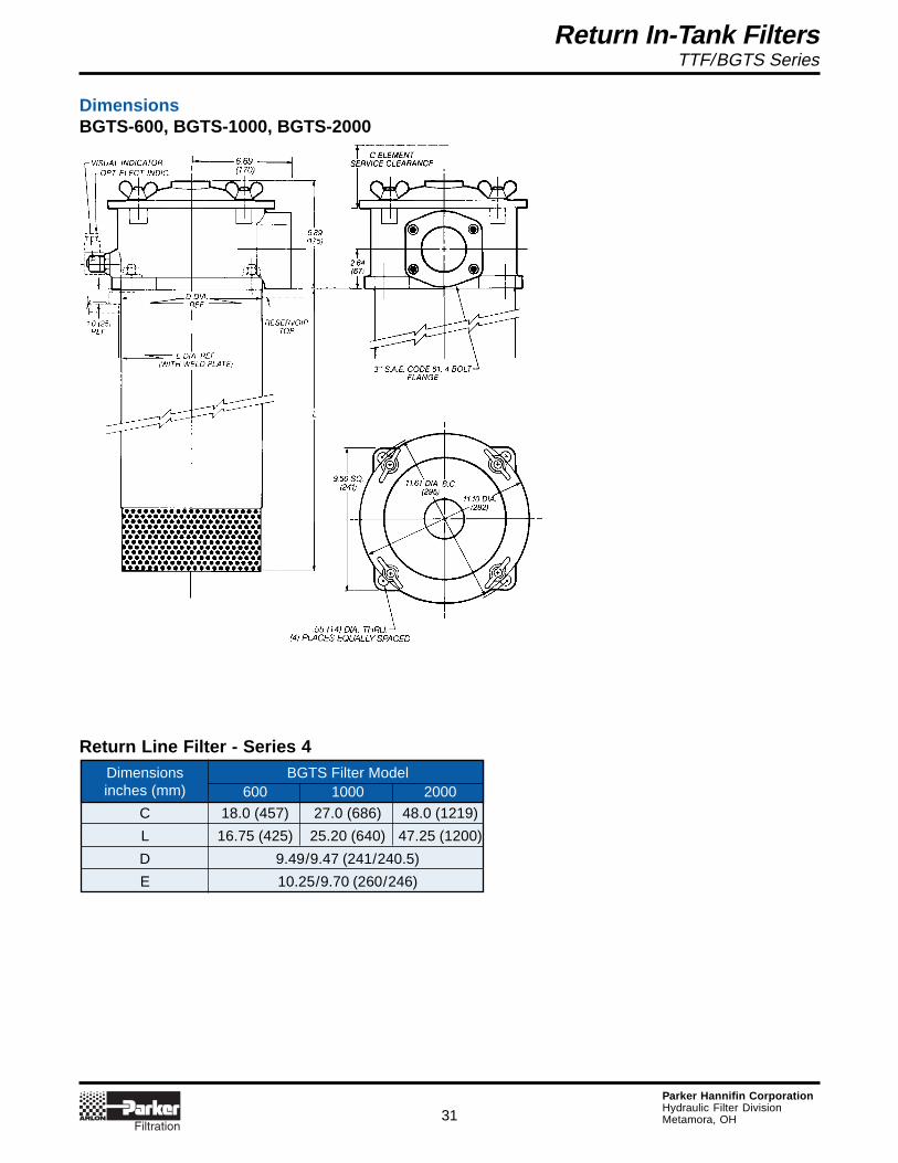
Dimensions BGTS Filter Modelinches (mm) 600 1000 2000
C 18.0 (457) 27.0 (686) 48.0 (1219)
L 16.75 (425) 25.20 (640) 47.25 (1200)
D 9.49/9.47 (241/240.5)
E 10.25/9.70 (260/246)
DimensionsBGTS-600, BGTS-1000, BGTS-2000
31
Return Line Filter - Series 4
Return In-Tank FiltersTTF/BGTS Series
Parker Hannifin CorporationHydraulic Filter DivisionMetamora, OH
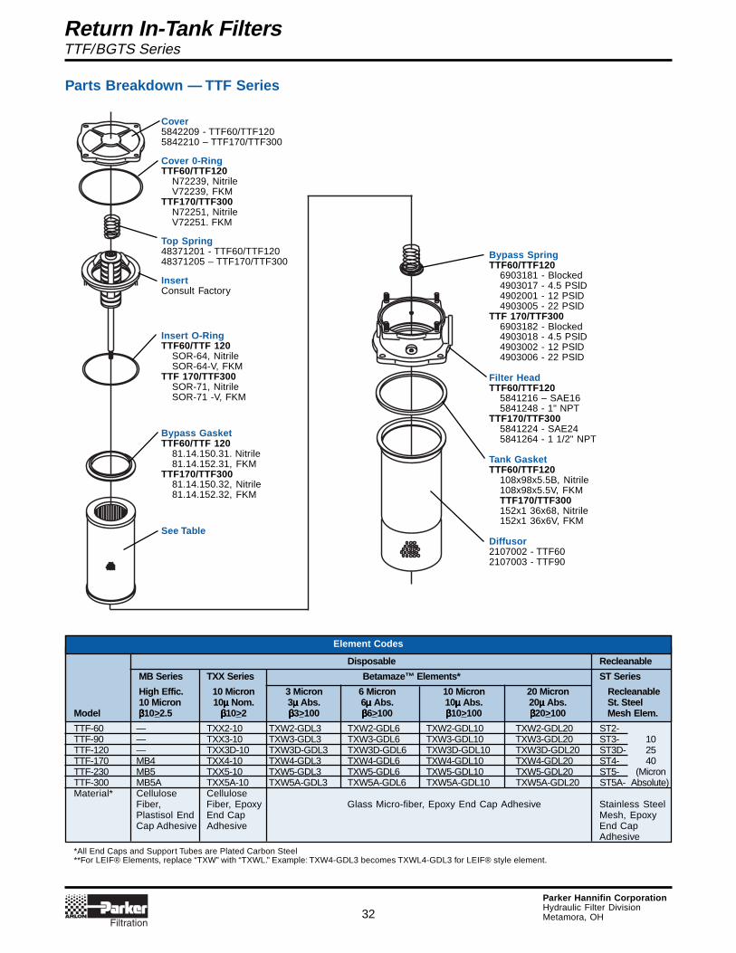
Parts Breakdown — TTF Series
Element Codes
Disposable Recleanable
MB Series TXX Series Betamaze™ Elements* ST Series
High Effic. 10 Micron 3 Micron 6 Micron 10 Micron 20 Micron Recleanable10 Micron 10µµµµµ Nom. 3µµµµµ Abs. 6µµµµµ Abs. 10µµµµµ Abs. 20µµµµµ Abs. St. Steel
Model βββββ10>2.5 βββββ10>2 βββββ3>100 βββββ6>100 βββββ10>100 βββββ20>100 Mesh Elem.
TTF-60 — TXX2-10 TXW2-GDL3 TXW2-GDL6 TXW2-GDL10 TXW2-GDL20 ST2-TTF-90 — TXX3-10 TXW3-GDL3 TXW3-GDL6 TXW3-GDL10 TXW3-GDL20 ST3- 10TTF-120 — TXX3D-10 TXW3D-GDL3 TXW3D-GDL6 TXW3D-GDL10 TXW3D-GDL20 ST3D- 25TTF-170 MB4 TXX4-10 TXW4-GDL3 TXW4-GDL6 TXW4-GDL10 TXW4-GDL20 ST4- 40TTF-230 MB5 TXX5-10 TXW5-GDL3 TXW5-GDL6 TXW5-GDL10 TXW5-GDL20 ST5- (MicronTTF-300 MB5A TXX5A-10 TXW5A-GDL3 TXW5A-GDL6 TXW5A-GDL10 TXW5A-GDL20 ST5A- Absolute)Material* Cellulose Cellulose
Fiber, Fiber, Epoxy Glass Micro-fiber, Epoxy End Cap Adhesive Stainless SteelPlastisol End End Cap Mesh, EpoxyCap Adhesive Adhesive End Cap
Adhesive
*All End Caps and Support Tubes are Plated Carbon Steel**For LEIF® Elements, replace “TXW” with “TXWL.” Example: TXW4-GDL3 becomes TXWL4-GDL3 for LEIF® style element.
32
Cover5842209 - TTF60/TTF1205842210 – TTF170/TTF300
Cover 0-RingTTF60/TTF120
N72239, NitrileV72239, FKM
TTF170/TTF300N72251, NitrileV72251. FKM
Top Spring48371201 - TTF60/TTF12048371205 – TTF170/TTF300
InsertConsult Factory
Insert O-RingTTF60/TTF 120
SOR-64, NitrileSOR-64-V, FKM
TTF 170/TTF300SOR-71, NitrileSOR-71 -V, FKM
Bypass GasketTTF60/TTF 120
81.14.150.31. Nitrile81.14.152.31, FKM
TTF170/TTF30081.14.150.32, Nitrile81.14.152.32, FKM
See Table
Bypass SpringTTF60/TTF120
6903181 - Blocked4903017 - 4.5 PSlD4902001 - 12 PSlD4903005 - 22 PSlD
TTF 170/TTF3006903182 - Blocked4903018 - 4.5 PSlD4903002 - 12 PSlD4903006 - 22 PSlD
Filter HeadTTF60/TTF120
5841216 – SAE165841248 - 1" NPT
TTF170/TTF3005841224 - SAE245841264 - 1 1/2" NPT
Tank GasketTTF60/TTF120
108x98x5.5B, Nitrile108x98x5.5V, FKMTTF170/TTF300152x1 36x68, Nitrile152x1 36x6V, FKM
Diffusor2107002 - TTF602107003 - TTF90

Return In-Tank FiltersTTF/BGTS Series
Parker Hannifin CorporationHydraulic Filter DivisionMetamora, OH
Parts Breakdown — BGTS Series
Seals
Part Numbers Description
BGTS BGTS390 or 500 600, 1000 or 2000
R-8575 R-8875 Cover O-RingR-208 SOR-90 Insert O-Ring
81.14.150.33-Buna SOR-85 Bypass Seals
81.14.152.33-FKM —
182 x 164 x 4 R8975 Tank Gasket
SOR-113 SOR-115 Element O-Ring
Nitrile or FKM Material*
*Please specify seal material suffix when ordering Fluorocarbon seals: “-V”
Bypass Assembly
390 Or 500 600, 1000 Or 2000 Pressure
6903183 6903184 Blocked4903019 4903020 4.5 PSID4903003 4903004 12 PSID4903007 4903008 22 PSID
Part NumbersItem Description Material BGTS-390 BGTS-500 BGTS-600 BGTS-1000 BGTS-2000
1 Top Spring Steel 83.07.012.03 48371205
2 Cover Die Cast 84.22.064.04 84.22.064.06Aluminum (5842204) (5842206)
3 Head Die Cast 84.10.064.22 5841032Aluminum (5841031)
4 Insert Assy. BridgeAluminum
Shaft- Steel, 13080000 13090000 14100000 14120000 14140000Magnets –Ceramic
5 Diffusor Steel 21100008 21100009 2110084 2110085 21100086
Element Codes
Disposable Recleanable**
MB Series TXX Series Betamaze™ Elements* ST Series
High Effic. 10 Micron 3 Micron 6 Micron 10 Micron 20 Micron Recleanable10 Micron Nominal Absolute Absolute Absolute Absolute St. Steel
Model βββββ10>2.5 βββββ10>2 βββββ3>100 βββββ6>100 βββββ10>100 βββββ25>100 Mesh Elem.
BGTS-390** MB8A TXX8A-10 TXW8A-GDL3 TXW8A-GDL6 TXW8A-GDL10 TXW2-GDL20 ST8A-BGTS-500** MB8C TXX8C-10 TXW8C-GDL3 TXW8C-GDL6 TXW8C-GDL10 TXW8C-GDL20 ST8C- 10BGTS-600** — TXX10-10 TXW10-GDL3 TXW10-GDL6 TXW10-GDL10 TXW10-GDL20 ST10- 25BGTS-1000** — TXX12-10 TXW12-GDL3 TXW12-GDL6 TXW12-GDL10 TXW12-GDL20 ST12- 40BGTS-2000 — TXX14-10 TXW14-GDL3 TXW14-GDL6 TXW14-GDL10 TXW14-GDL20 ST14- (Micron
Absolute)Material* Cellulose Cellulose
Fiber, Fiber, Epoxy Glass Micro-fiber, Epoxy End Cap Adhesive Stainless SteelPlastisol End End Cap Mesh, EpoxyCap Adhesive Adhesive End Cap
Adhesive
*All End Caps and Support Tubes are Plated Carbon Steel **Coarser ratings available: Consult Factory**For LEIF® Elements, replace “TXW” with “TXWL.” Example: TXW8C-GDL10 becomes TXWL8C-GDL10 for LEIF® style element.
33
2 1
3
4
5
See Table
Return In-Tank FiltersTTF/BGTS Series
Parker Hannifin CorporationHydraulic Filter DivisionMetamora, OH
Operating And Maintenance Instructions
Arlon Model TTF And BGTS Tank Top Filters
A. Mounting
1. Standard mounting.a. Cut proper size hole in the top of the reservoir.b. Drill holes for studs within the proper bolt circle.c. Set the filter into the cutout hole and secure with proper size bolts, nuts and lock washers.
2. Mounting procedure using Arlon weld plate.a. Rough cut proper size hole in the top of reservoir.b. Weld the weld plate concentric to the rough cut hole.c. Mount the filter onto the studs and secure with nuts and lock washers.
3. Utilize proper fittings.
B. Start-Up
1. Check for and eliminate leaks upon system start-up.
2. Check differential pressure indicator, if installed, to monitor element condition.
C. Service
1. An element must be serviced when the differential pressure indicator indicates service is required.
NOTE: If the filter is not equipped with a differential pressure indicator, the element should be serviced according tomachine manufacturer’s instructions.
D. Servicing Dirty Elements
1. Shut system down to assure that there is NO PRESSURE OR FLOW into the filter housing.
2. Remove the filter cover.
3. Remove the filter insert (bridge which holds the element in place).
4. Remove the bypass spring assembly or non-bypass plate from the stud.
5. Remove the contaminated cartridge with a twisting motion.
6. a. Discard the disposable element cartridge.
b. Wash cleanable or mesh elements in a non-caustic solvent. Compressed air can be used to facilitate cleaning.Use care to prevent damage to the element during cleaning.
NOTE: Elements finer than 150 microns (100 mesh) may require special ultrasonic cleaning.Consult factory for recommendations.
E. Before Installing A New Element Cartridge
1. Clean the magnetic core with a lint-free cloth.
2. Check all seals and replace if necessary.
F. To Install A New Or Cleaned Element Cartridge
1. Lubricate all seals.
2. Mount new or cleaned Arlon filter cartridge.
NOTE: For ease of mounting, hold the cartridge away from the magnetic core until the stud is through the hole inthe bottom of the element. Then slide it up to securely seat it to the top of the bridge.
3. Install the bypass spring assembly or non-bypass plate, and tighten until snug.
NOTE: Older versions may have a cotter pin/castellated nut retained bypass spring. In these cases, the nut should beturned down the shaft until the cross drilled hole is visible in the base of a castellation and the cotter pin inserted andends flared to lock the bypass assembly in place.
4. Re-install the insert into the filter housing, making sure that the top-spring is secure.
5. Re-install the cover. Torque the cover nuts to 35 ft./lbs.
Follow procedures B.1 and B.2.
34

Return In-Tank FiltersTTF/BGTS Series
Parker Hannifin CorporationHydraulic Filter DivisionMetamora, OH
HOW TO ORDER:Select the desired symbol (in the correct position) to construct a model code.Assembly Example:
BOX 1 BOX 2 BOX 3 BOX 4 STD BOX 5 BOX 6 BOX 7
TTF-230 S24 TXW5-GDL10 B T 22 S TP
BOX 1: MODELSymbol Description
FULL FLOW SURGE FLOWTTF-60 16 GPM (60 l/min) 30 GPM (110 l/min)
TTF-90 24 GPM (90 l/min) 40 GPM (150 l/min)
TTF-120 32 GPM (120 l/min) 50 GPM (190 l/min)
TTF-170 50 GPM (190 l/min) 80 GPM (300 l/min)
TTF-230 60 GPM (230 l/min) 100 GPM (375 l/min)
TTF-300 80 GPM (300 l/min) 120 GPM (450 l/min)
BGTS-390 105 GPM (400 l/min) 150 GPM (565 l/min)
BGTS-500 135 GPM (510 l/min) 200 GPM (755 l/min)
BGTS-600 160 GPM (600 l/min) 220 GPM (830 l/min)
BGTS-1000 265 GPM (1000 l/min) 330 GPM (1250 l/min)
BGTS-2000 530 GPM (2000 l/min) 640 GPM (2420 l/min)
Element Example:
BOX 3 BOX 4
TXW5-GDL10 B
BOX 2 : PORTSSymbol Description
TTF-60/90/120S16 SAE-16 (1 1/16”-12)N10 1” NPT
TTF-170/230/300S24 SAE-24 (1 5/16”-12)N15 1 ½” NPT
BGTS-390/500F2 2” Code 61 SAE Flange
BGTS-600/1000/2000F3 3” Code 61 SAE Flange
Please note the bolded options reflectstandard options with a reducedlead- time. Consult factory on all otherlead-time options.
BOX 3 : ELEMENTModel Symbol
10µµµµµ Nom. 10µµµµµ Nom. 3µµµµµ Abs. 6µµµµµ Abs. 10µµµµµ Abs. 20µµµµµ Abs. St. Steelβββββ10>2.5 βββββ10>2 βββββ3>100 βββββ6>100 βββββ10>100 βββββ20>100 Cleanable
TTF-60 — TXX2-10 TXW2-GDL3 TXW2-GDL6 TXW2-GDL10 TXW2-GDL20 ST2-TTF-90 — TXX3-10 TXW3-GDL3 TXW3-GDL6 TXW3-GDL10 TXW3-GDL20 ST3-TTF-120 — TXX3D-10 TXW3D-GDL3 TXW3D-GDL6 TXW3D-GDL10 TXW3D-GDL20 ST3D-TTF-170 MB4 TXX4-10 TXW4-GDL3 TXW4-GDL6 TXW4-GDL10 TXW4-GDL20 ST4- 10TTF-230 MB5 TXX5-10 TXW5-GDL3 TXW5-GDL6 TXW5-GDL10 TXW5-GDL20 ST5- 25TTF-300 MB5A TXX5A-10 TXW5A-GDL3 TXW5A-GDL6 TXW5A-GDL10 TXW5A-GDL20 ST5A- 40BGTS-390 MB8A TXX8A-10 TXW8A-GDL3 TXW8A-GDL6 TXW8A-GDL10 TXW8A-GDL20 ST8A- 60BGTS-500 MB8C TXX8C-10 TXW8C-GDL3 TXW8C-GDL6 TXW8C-GDL10 TXW8C-GDL20 ST8C- 120BGTS-600 — TXX10-10 TXW10-GDL3 TXW10-GDL6 TXW210-GDL10 TXW10-GDL20 ST10-BGTS-1000 — TXX12-10 TXW12-GDL3 TXW12-GDL6 TXW12-GDL10 TXW12-GDL20 ST12-BGTS-2000 — TXX14-10 TXW14-GDL3 TXW14-GDL6 TXW14-GDL10 TXW14-GDL20 ST14-
B Nitrile (Buna)V Fluorocarbon (FKM)
BOX 4 : SEALSSymbol Description
B Blocked
12 12 PSID (0.8 Bar)
22 22 PSID (1.2 Bar)
BOX 5 : BYPASSSymbol Description
TP Weld PlateOMIT If not required
BOX 7 : OPTIONSSymbol Description
G 0-30 PSIG GaugeS Pressure Switch w/½” ConduitW Pressure Switch w/3 Wire LeadsV Visual Indicator
(BGTS-600/2000 only)E Electrical Indicator w/Hirschmann
(BGTS-600/2000 only)OMIT No Indicator
BOX 6 : INDICATORSymbol Description
35

Return In-Tank FiltersTTF/BGTS Series
Parker Hannifin CorporationHydraulic Filter DivisionMetamora, OH
Notes
36