Embed Size (px)
Citation preview
RULES
PUBLICATION NO. 87/P
APPLICATION OF THE PERFORMANCE STANDARD FOR PROTECTIVE COATINGS
UNDER REQUIREMENTS CONCERNING THE CONSTRUCTION OF SEA-GOING BULK CARRIERS
AND SEA-GOING DOUBLE HULL OIL TANKERS
2012
Publications P (Additional Rule Requirements) issued by Polski Rejestr Statków complete or extend the Rules and are mandatory where applicable.
GDAŃSK
RULES
PUBLICATION NO. 87/P
APPLICATION OF THE PERFORMANCE STANDARD FOR PROTECTIVE COATINGS
UNDER REQUIREMENTS CONCERNING THE CONSTRUCTION OF SEA-GOING BULK CARRIERS
AND SEA-GOING DOUBLE HULL OIL TANKERS
2012
GDAŃSK
PRS Publication No. 87/P – Application of the Performance Standard for Protective Coatings under Requirements Concerning the Construction of Sea-going Bulk Carriers and Sea-going Double Hull Oil Tankers – 2012, is an extension of the requirements contained in Publication No. 84/P – Requirements Concerning the Construction and Strength of the Hull and Hull Equipment of Sea-going Bulk Carriers of 90 m in Length and Above and the Publication No. 85/P – Requirements Concerning the Construction and Strength of the Hull and Hull Equipment of Sea-going, Double Hull Oil Tankers of 150 m in Length and Above and in Part II “Hull” of the Rules for the Classification and Construction of Sea-Going Ships, as well as in all other PRS Rules, where reference to the Publication has been made.
This Publication was approved by PRS Executive Board on 14 March 2012 and enters into force on 20 March 2012.
The present Publication replaces Publication No. 87/P – Application of the Perform-ance Standard for Protective Coatings (PSPC) under Requirements Concerning the Con-struction and Strength of the Hull and Hull Equipment of Sea-going Bulk Carriers of 90 m in Length and Above – 2010, including the issued Amendments thereto – No. 1/2010.
© Copyright by Polski Rejestr Statków S.A., 2012
PRS/AW, 02/2012
ISBN 978-83-7664-069-3
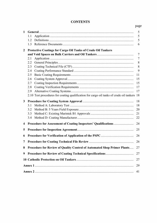
CONTENTS page
1 General ....................................................................................................................... 5 1.1 Application ......................................................................................................... 5 1.2 Definitions .......................................................................................................... 5 1.3 Reference Documents ......................................................................................... 6
2 Protective Coatings for Cargo Oil Tanks of Crude Oil Tankers and Void Spaces on Bulk Carriers and Oil Tankers .............................................. 7 2.1 Application ......................................................................................................... 7 2.2 General Principles............................................................................................... 8 2.3 Coating Technical File (CTF)............................................................................. 8 2.4 Coating Performance Standard ........................................................................... 9 2.5 Basic Coating Requirements............................................................................... 11 2.6 Coating System Approval ................................................................................... 15 2.7 Coating Inspection Requirements ....................................................................... 15 2.8 Coating Verification Requirements .................................................................... 17 2.9 Alternative Coating Systems............................................................................... 17 2.10 Test procedures for coating qualification for cargo oil tanks of crude oil tankers 18
3 Procedure for Coating System Approval ................................................................ 18 3.1 Method A: Laboratory Test ................................................................................ 18 3.2 Method B: 5 Years Field Exposure..................................................................... 20 3.3 Method C: Existing Marintek B1 Approvals ...................................................... 21 3.4 Method D: Coating Manufacturer....................................................................... 22
4 Procedure for Assessment of Coating Inspectors’ Qualifications ......................... 24 5 Procedure for Inspection Agreement....................................................................... 25 6 Procedure for Verification of Application of the PSPC ......................................... 26 7 Procedure for Coating Technical File Review ........................................................ 26 8 Procedure for Review of Quality Control of Automated Shop Primer Plants..... 27 9 Procedure for Review of Coating Technical Specifications ................................... 27 10 Cathodic Protection on Oil Tankers ........................................................................ 27 Annex 1 ............................................................................................................................ 29 Annex 2 ............................................................................................................................ 41
1 GENERAL
1.1 Application
1.1.1 These Rules apply to ships classed with the Polski Rejestr Statków (called PRS hereafter).
1.1.2 These Rules shall be applied by PRS to: – bulk carriers subject to the Publication No. 84/P – Requirements Concerning
the Construction and Strength of the Hull and Hull Equipment of Sea-going Bulk Carriers of 90 m in Length and Above, contracted for construction on or after 1 July 2009;
– oil tankers subject to the Publication No. 85/P – Requirements Concerning the Construction and Strength of the Hull and Hull Equipment of Sea-going, Dou-ble Hull Oil Tankers of 150 m in Length and Above, contracted for construction on or after 1 September 2010;
– bulk carriers and oil tankers of 500 gross tonnage and upwards, contracted for construction on or after 1 July 2008;
– crude oil tankers of 5,000 gross tonnage and upwards, contracted for construc-tion on or after 1 January 2013.
1.2 Definitions
Definitions concerning general terminology applied in PRS Rules are contained in the Rules. For the purpose of this Publication, the following additional defini-tions have been adopted:
.1 C r u d e o i l t a n k e r – as defined in Annex I of MARPOL 73/78.
.2 C T F – coating technical file. A term used for the collection of documents describing issues related to the coating system and its application from the point in time when the first document is provided and for the entire life of the ship including the inspection agreement.
.3 D e w p o i n t – the temperature at which air is saturated with moisture.
.4 D F T – dry film thickness.
.5 D u s t – loose particle matter present on a surface prepared for painting, arising from blast-cleaning or other surface preparation processes, or re-sulting from action of the environment.
.6 E d g e g r i n d i n g – the treatment of edge before secondary surface preparation.
.7 G O O D c o n d i t i o n – the condition with only minor spot rusting. Con-dition with spot rusting on less than 3% of the area under consideration without visible failure of the coating. Rusting at edges or welds, must be on less than 20 % of edges or weld lines in the area under consideration.
.8 H a r d c o a t i n g − a coating that chemically converts during its curing process or non-convertible air drying coating which may be used for main-tenance purposes. Hard coating can be either inorganic or organic.
5
.9 N D F T – the nominal dry film thickness.
.10 9 0 / 1 0 p r a c t i c e – the practice means that 90% of all thickness meas-urements shall be greater than, or equal to, NDFT and none of the remain-ing 10% measurements shall be below 90% NDFT.
.11 P r i m e r c o a t – the first coat of the coating system applied in the ship-yard after shop-primer application.
.12 P S P C – performance standard for protective coatings according to the Resolution MSC.215(82).
.13 S h o p – p r i m e r – the prefabrication primer coating applied to steel plates, often in automatic plants (and before the first coat of a coating system).
.14 S t r i p e c o a t i n g – painting, by a brush or a roller, of edges, welds, hard to reach areas, etc., to ensure good paint adhesion and proper paint thick-ness in critical areas.
.15 T a r g e t u s e f u l l i f e – the target value, in years, of durability for which the coating system is designed.
.16 T e c h n i c a l D a t a S h e e t – paint manufacturer’s Product Data Sheet which contains the detailed technical instructions and information relevant to the coating and its application.
.17 T o t a l l y e n c l o s e d s p a c e – the space which has no means of access and no ventilation.
.18 V o i d s p a c e – an enclosed space below the bulkhead deck, within and forward of, the cargo area of oil tankers or the cargo length area of bulk carriers, excluding: (a) a dedicated seawater ballast tank; (b) a space for the carriage of cargo; (c) a space for the storage of any substance (e.g., oil fuel, fresh water, pro-
visions); (d) a space for the installation of any machinery (e.g., cargo pump, ballast
pump, bow thruster); (e) any space in normal use by personnel; and (f) a double-side skin space of bulk carriers of 150 m in length and up-
wards which shall comply with the Performance standard for dedicated seawater ballast tanks in all types of ships and double-side skin spaces of bulk carriers.
1.3 Reference Documents
Standards
(1) ISO 8501-1:2007 Preparation of steel substrates before application of paints and related products – Visual assessment of surface cleanliness – Part 1: Rust grades and preparation grades of uncoated steel substrates and of steel substrates after overall removal of previous coatings.
6
(2) ISO 8501-3:2006 Preparation of steel substrates before application of paints and related products – Visual assessment of surface cleanliness – Part 3: Prepara-tion grades of welds, edges and other areas with surface imperfections. (3) ISO 8502-3:1992 Preparation of steel substrates before application of paints and related products – Tests for the assessment of surface cleanliness – Part 3: As-sessment of dust on steel surfaces prepared for painting (pressure-sensitive tape method). (4) ISO 8502-9:1998 Preparation of steel substrates before application of paints and related products – Tests for the assessment of surface cleanliness – Part 9: Field method for the conductometric determination of water-soluble salts. (5) ISO 8503-1:1988 Preparation of steel substrates before application of paints and related products – Surface roughness characteristics of blast-cleaned steel sub-strates – Part 1: Specifications and definitions for ISO surface profile comparators for the assessment of abrasive blast-cleaned surfaces. (6) ISO 8503-2:1988 Preparation of steel substrates before application of paints and related products – Surface roughness characteristics of blast-cleaned steel sub-strates – Part 2: Method for the grading of surface profile of abrasive blast-cleaned steel – Comparator procedure. (7) NACE SP0508-2010 Item no. 21134 Standard practice methods of validating equivalence to ISO 8502-9 on measurement of the levels of soluble salts.
Other Documents (I) IMO Resolution MSC.215(82) Performance Standard for Protective Coatings for Dedicated Seawater Ballast Tanks in All Types of Ships and Double-Side Skin Spaces of Bulk Carriers
2 PROTECTIVE COATINGS FOR CARGO OIL TANKS OF CRUDE OIL TANKERS AND VOID SPACES ON BULK CARRIERS AND OIL TANKERS
2.1 Application
2.1.1 Chapter 2 provides technical requirements for the minimum standard for protective coatings to be applied in cargo oil tanks during the construction of new crude oil tankers and for protective coatings for void spaces constructed of steel in bulk carriers and oil tankers.
2.1.2 The provisions of Chapter 2 apply to cargo oil tanks of crude oil tankers and void spaces on bulk carriers and oil tankers mentioned in paragraph 1.1.2.
2.1.3 Protective coatings in dedicated seawater ballast tanks and double-side skin spaces on ships, which are subject to PRS survey mentioned in paragraph 1.1.2 shall comply with the requirements specified in Publication No. 55/P – Survey of corrosion protection and anti-fouling systems.
7
2.2 General Principles
2.2.1 The ability of the coating system to reach its target useful life depends on the type of the coating system, steel preparation, operating environment, applica-tion and coating inspection and maintenance.
2.2.2 Inspections relevant to surface preparation and coating processes shall be agreed upon between the Shipowner, the shipyard and the coating manufacturer, presented to the PRS for review. Clear evidence of the above-mentioned inspec-tions shall be reported and included in the Coating Technical File (CTF).
2.2.3 Specifications, procedures and the various different steps in the coating application process (including, but not limited to, surface preparation) shall be strictly applied by the shipbuilder in order to prevent premature decay and/or dete-rioration of the coating system.
2.2.4 The coating performance can be improved by adopting measures at the ship design stage such as reducing scallops, using rolled profiles, avoiding complex geometric configurations and ensuring that the structural configuration permits easy access for tools and to facilitate cleaning, drainage and drying of the space to be coated.
2.3 Coating Technical File (CTF)
2.3.1 Coating Technical File (CTF) shall contain specification of the coating sys-tem applied to cargo oil tanks of crude oil tankers and to void spaces in bulk carriers and oil tankers, record of the shipyard’s and Shipowner’s coating work, detailed criteria for coating selection, job specifications, inspection, maintenance and repair.
The Coating Technical File (CTF) shall be submitted to PRS for review.
2.3.2 The Coating Technical File (CTF) on new ship construction stage shall be delivered by the shipyard and shall contain at least the following:
.1 a copy of Type Approval Certificate and Statement of Compliance of coat-ing system;
.2 a copy of Type Approval Certificate of corrosion resistant steel (if any);
.3 Technical Data Sheets of coating system;
.4 technical data of corrosion resistant steel (if any), including approved welding methods and welding consumables and repairing methods recom-mended by the manufacturer;
.5 Material Safety Data Sheets;
.6 shipyard work records of coating application specifying actual areas (in square metres) of coating in each cargo oil tank or actual space and area (in square metres) of each void space, type of the applied coating system, time of coating, thickness, number of layers, ambient conditions (during coat-ing), the method of surface preparation and additionally (if any) for using corrosion resistant steel actual space and area of each compartment and applied product and its thickness;
8
.7 inspection processes agreement signed by shipyard, shipowner and coating manufacturer;
.8 procedures for inspection and repair of coating system during ship con-struction;
.9 coating log issued by the coating inspector stating that the coating was ap-plied in accordance with the specifications to the satisfaction of the coating supplier representative and specifying deviations from the specifications;
.10 inspection report;
.11 procedures for in-service maintenance and repair of the coating system.
2.3.3 The Coating Technical File (CTF) shall contain records of in-service main-tenance, carried out repairs and partial re-coating activities.
2.3.4 Full re-coating process shall be recorded in the Coating Technical File (CTF) within the scope specified in 2.3.2.
2.3.5 The Coating Technical File (CTF) shall be kept on board and maintained throughout the life of the ship.
2.4 Coating Performance Standard
2.4.1 The requirements set forth in the present Publication intend to provide a target useful coating life of 15 years, which is considered to be the time period, from initial application, over which the coating system will remain in “GOOD”. condition. The actual useful life will vary, depending on numerous variables in-cluding actual conditions encountered in service.
2.4.2 The following areas of cargo oil tanks of new crude oil tankers are the minimum areas that shall be protected according to requirements specified in Chapter 2 of the present Publication:
.1
.2
.3
.4
Deckhead with complete internal structure, including brackets connecting to longitudinal and transverse bulkheads. In tanks with ring frame girder construction, the underdeck transverse framing to be coated down to level of the first tripping bracket below the upper faceplate. Longitudinal and transverse bulkheads to be coated to the uppermost means of access level. The uppermost means of access and its supporting brackets to be fully coated. On cargo tank bulkheads without an uppermost means of access the coat-ing to extend to 10% of the tanks height at centreline but need not extend more than 3 m down from the deck. Flat inner bottom and all structure to the height of 0.3 m above inner bot-tom to be coated.
9
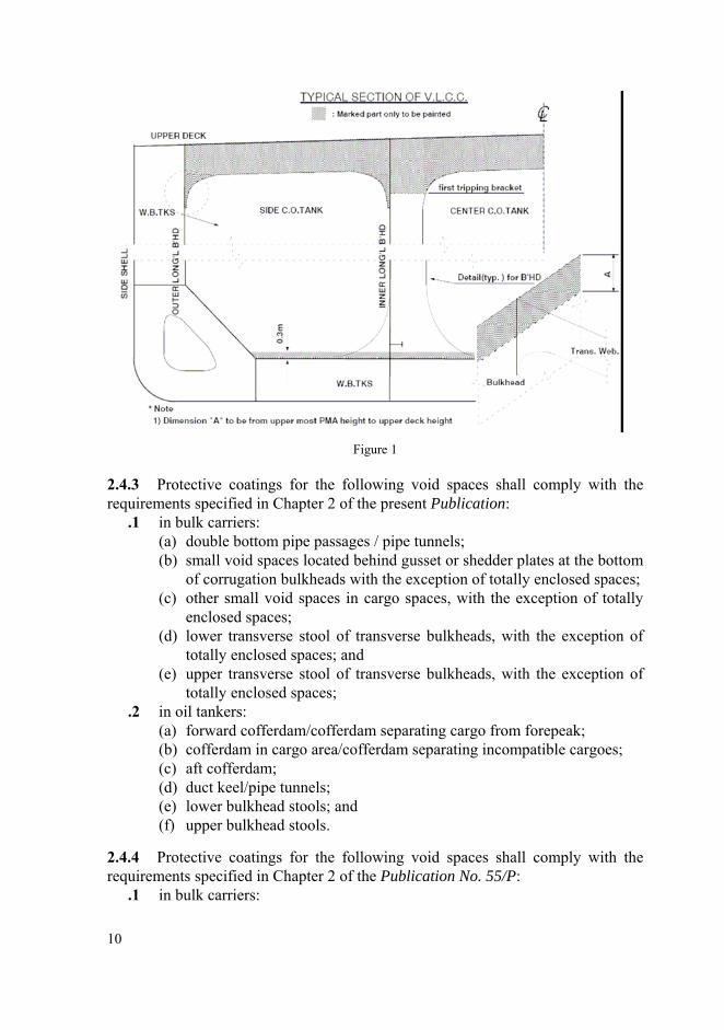
Figure 1
2.4.3 Protective coatings for the following void spaces shall comply with the requirements specified in Chapter 2 of the present Publication:
.1 in bulk carriers: (a) double bottom pipe passages / pipe tunnels; (b) small void spaces located behind gusset or shedder plates at the bottom
of corrugation bulkheads with the exception of totally enclosed spaces; (c) other small void spaces in cargo spaces, with the exception of totally
enclosed spaces; (d) lower transverse stool of transverse bulkheads, with the exception of
totally enclosed spaces; and (e) upper transverse stool of transverse bulkheads, with the exception of
totally enclosed spaces; .2 in oil tankers:
(a) forward cofferdam/cofferdam separating cargo from forepeak; (b) cofferdam in cargo area/cofferdam separating incompatible cargoes; (c) aft cofferdam; (d) duct keel/pipe tunnels; (e) lower bulkhead stools; and (f) upper bulkhead stools.
2.4.4 Protective coatings for the following void spaces shall comply with the requirements specified in Chapter 2 of the Publication No. 55/P:
.1 in bulk carriers:
10

(a) double-side skin spaces in ships of less than 150 m in length; and (b) upper and lower side void spaces and double bottoms void spaces in
cargo area; .2 in oil tankers:
(a) double-side skin (DSS) voids including sides, bottoms/double hull voids spaces protecting cargo oil tanks.
2.4.5 No requirements are contained in this Publication for protective coatings for the following void spaces in bulk carriers and oil tankers:
.1 totally enclosed spaces located behind gusset or shedder plates at the bot-tom of corrugation bulkheads and other small totally enclosed spaces in cargo tanks;
.2
.3
.4
.5
lower transverse stool of transverse bulkheads that are totally enclosed spaces; upper transverse stool of transverse bulkheads that are totally enclosed spaces; transducer voids; and any spaces not specifically mentioned in paragraphs 2.4.3 and 2.4.4.
2.4.6 The requirements of the present Publication cover protective coatings for the ship’s steel structure. Access arrangements that are integral to the ship’s struc-ture, such as increased stiffener depths for walkways, stringers, etc., are to fully comply with this Publication when located within the coated areas.
2.4.7 It is recommended that the requirements of Chapter 2 should be applied, to the extent possible, to those portions of permanent means of access provided for inspection, not integral to the ship’s structure, such as rails, independent platforms, ladders, etc. Other equivalent methods of providing corrosion protection for the non-integral items may also be used, provided they do not impair the performance of the coatings of the surrounding structure.
2.4.8 It is also recommended that supports for piping, measuring devices, etc., be coated in accordance with the provisions for non-integral items indicated in para-graph 2.4.7.
2.5 Basic Coating Requirements
2.5.1 The requirements for protective coating systems to be applied at ship con-struction for the cargo oil tanks of crude oil tankers and void spaces in bulk carriers and oil tankers meeting the criteria specified in paragraph 2.4.1, are listed in table 1.
2.5.2 Coating manufacturers shall provide a specification of the protective coat-ing system to satisfy the requirements of table 1 and the operating environment.
2.5.3 The Technical Data Sheet, as well as Type Approval Certificate and State-ment of Compliance for the protective coating system shall be submitted to PRS for verification.
11
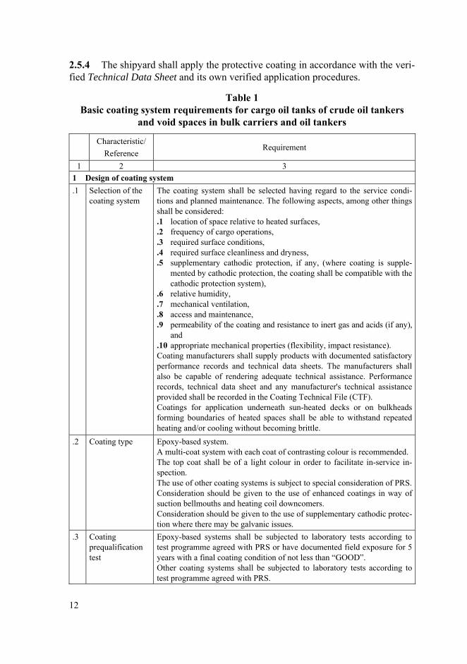
2.5.4 The shipyard shall apply the protective coating in accordance with the veri-fied Technical Data Sheet and its own verified application procedures.
Table 1 Basic coating system requirements for cargo oil tanks of crude oil tankers
and void spaces in bulk carriers and oil tankers Characteristic/
Reference Requirement
1 2 3 1 Design of coating system .1 Selection of the
coating system The coating system shall be selected having regard to the service condi-tions and planned maintenance. The following aspects, among other things shall be considered: .1 location of space relative to heated surfaces, .2 frequency of cargo operations, .3 required surface conditions, .4 required surface cleanliness and dryness, .5 supplementary cathodic protection, if any, (where coating is supple-
mented by cathodic protection, the coating shall be compatible with the cathodic protection system),
.6 relative humidity,
.7 mechanical ventilation,
.8 access and maintenance,
.9 permeability of the coating and resistance to inert gas and acids (if any), and
.10 appropriate mechanical properties (flexibility, impact resistance). Coating manufacturers shall supply products with documented satisfactory performance records and technical data sheets. The manufacturers shall also be capable of rendering adequate technical assistance. Performance records, technical data sheet and any manufacturer's technical assistance provided shall be recorded in the Coating Technical File (CTF). Coatings for application underneath sun-heated decks or on bulkheads forming boundaries of heated spaces shall be able to withstand repeated heating and/or cooling without becoming brittle.
.2 Coating type Epoxy-based system. A multi-coat system with each coat of contrasting colour is recommended. The top coat shall be of a light colour in order to facilitate in-service in-spection. The use of other coating systems is subject to special consideration of PRS. Consideration should be given to the use of enhanced coatings in way of suction bellmouths and heating coil downcomers. Consideration should be given to the use of supplementary cathodic protec-tion where there may be galvanic issues.
.3 Coating prequalification test
Epoxy-based systems shall be subjected to laboratory tests according to test programme agreed with PRS or have documented field exposure for 5 years with a final coating condition of not less than “GOOD”. Other coating systems shall be subjected to laboratory tests according to test programme agreed with PRS.
12
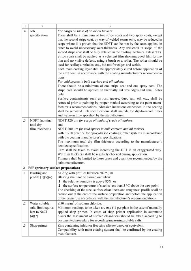
1 2 3 .4 Job
specification For cargo oil tanks of crude oil tankers: There shall be a minimum of two stripe coats and two spray coats, except that the second stripe coat, by way of welded seams only, may be reduced in scope where it is proven that the NDFT can be met by the coats applied, in order to avoid unnecessary over-thickness. Any reduction in scope of the second stripe coat shall be fully detailed in the Coating Technical File (CTF). Stripe coats shall be applied as a coherent film showing good film forma-tion and no visible defects, using a brush or a roller. The roller should be used for scallops, ratholes, etc., but not for edges and welds. Each main coating layer shall be appropriately cured before application of the next coat, in accordance with the coating manufacturer’s recommenda-tions. For void spaces in bulk carriers and oil tankers: There should be a minimum of one stripe coat and one spray coat. The stripe coat should be applied on thermally cut free edges and small holes only. Surface contaminants such as rust, grease, dust, salt, oil, etc., shall be removed prior to painting by proper method according to the paint manu-facturer’s recommendations. Abrasive inclusions embedded in the coating shall be removed. Job specifications shall include the dry-to-recoat times and walk-on time specified by the manufacturer.
.5 NDFT (nominal total dry film thickness)
NDFT 320 µm for cargo oil tanks of crude oil tankers and NDFT 200 µm for void spaces in bulk carriers and oil tankers with 90/10 practice for epoxy-based coatings; other systems in accordance with the coating manufacturer’s specifications. The maximum total dry film thickness according to the manufacturer’s detailed specifications. Care shall be taken to avoid increasing the DFT in an exaggerated way. Wet film thickness shall be regularly checked during application. Thinners shall be limited to those types and quantities recommended by the paint manufacturer.
2 PSP (primary surface preparation) .1 Blasting and
profile (1)(5)(6)Sa 21/2; with profiles between 30-75 μm Blasting shall not be carried out when: .1 the relative humidity is above 85%, or .2 the surface temperature of steel is less than 3 °C above the dew point. The checking of the steel surface cleanliness and roughness profile shall be carried out at the end of the surface preparation and before the application of the primer, in accordance with the manufacturer’s recommendations.
.2 Water soluble salts limit equiva-lent to NaCl (4)(7)
≤ 50 mg/m2 of sodium chloride. Minimum readings to be taken are one (1) per plate in the case of manually applied shop primer. In cases of shop primer application in automatic plants the assessment of surface cleanliness should be taken according to documented procedure for recording/measuring soluble salts.
.3 Shop-primer Zinc containing inhibitor free zinc silicate based or equivalent. Compatibility with main coating system shall be confirmed by the coating manufacturer.
13
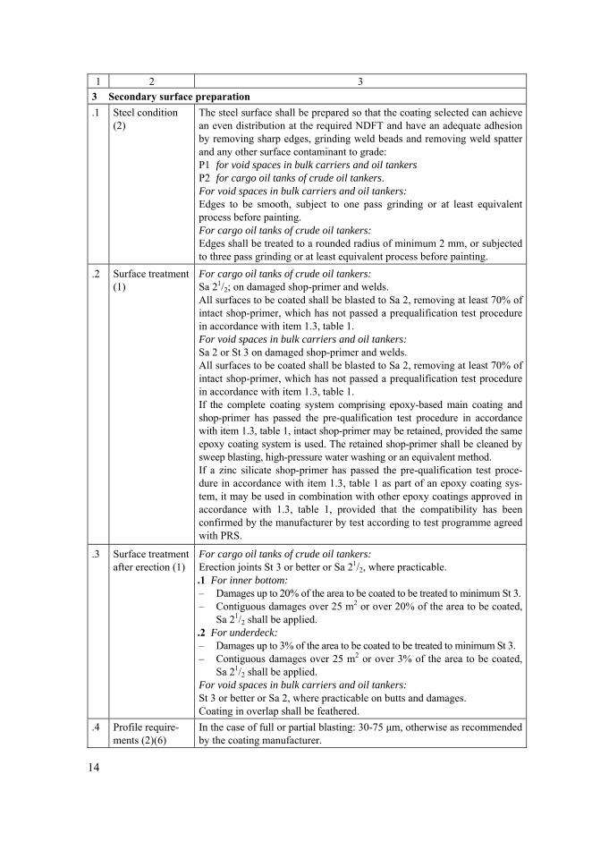
1 2 3 3 Secondary surface preparation .1 Steel condition
(2)The steel surface shall be prepared so that the coating selected can achieve an even distribution at the required NDFT and have an adequate adhesion by removing sharp edges, grinding weld beads and removing weld spatter and any other surface contaminant to grade: P1 for void spaces in bulk carriers and oil tankers P2 for cargo oil tanks of crude oil tankers. For void spaces in bulk carriers and oil tankers: Edges to be smooth, subject to one pass grinding or at least equivalent process before painting. For cargo oil tanks of crude oil tankers: Edges shall be treated to a rounded radius of minimum 2 mm, or subjected to three pass grinding or at least equivalent process before painting.
.2 Surface treatment (1)
For cargo oil tanks of crude oil tankers: Sa 21/2; on damaged shop-primer and welds. All surfaces to be coated shall be blasted to Sa 2, removing at least 70% of intact shop-primer, which has not passed a prequalification test procedure in accordance with item 1.3, table 1. For void spaces in bulk carriers and oil tankers: Sa 2 or St 3 on damaged shop-primer and welds. All surfaces to be coated shall be blasted to Sa 2, removing at least 70% of intact shop-primer, which has not passed a prequalification test procedure in accordance with item 1.3, table 1. If the complete coating system comprising epoxy-based main coating and shop-primer has passed the pre-qualification test procedure in accordance with item 1.3, table 1, intact shop-primer may be retained, provided the same epoxy coating system is used. The retained shop-primer shall be cleaned by sweep blasting, high-pressure water washing or an equivalent method. If a zinc silicate shop-primer has passed the pre-qualification test proce-dure in accordance with item 1.3, table 1 as part of an epoxy coating sys-tem, it may be used in combination with other epoxy coatings approved in accordance with 1.3, table 1, provided that the compatibility has been confirmed by the manufacturer by test according to test programme agreed with PRS.
.3 Surface treatment after erection (1)
For cargo oil tanks of crude oil tankers: Erection joints St 3 or better or Sa 21/2, where practicable. .1 For inner bottom: – Damages up to 20% of the area to be coated to be treated to minimum St 3. – Contiguous damages over 25 m2 or over 20% of the area to be coated,
Sa 21/2 shall be applied. .2 For underdeck: – Damages up to 3% of the area to be coated to be treated to minimum St 3. – Contiguous damages over 25 m2 or over 3% of the area to be coated,
Sa 21/2 shall be applied. For void spaces in bulk carriers and oil tankers: St 3 or better or Sa 2, where practicable on butts and damages. Coating in overlap shall be feathered.
.4 Profile require-ments (2)(6)
In the case of full or partial blasting: 30-75 μm, otherwise as recommended by the coating manufacturer.
14

1 2 3 .5 Dust (3) Dust quantity rating 1 for dust size class 3, 4 or 5.
Lower dust size classes should be removed if visible on the surface to be coated without magnification.
.6 Water soluble salts limit equiva-lent to NaCl after blasting/grinding (4)(7)
For cargo oil tanks of crude oil tankers: ≤ 50 mg/m2 of sodium chloride. For void spaces in bulk carriers and oil tankers: ≤ 100 mg/m2 of sodium chloride. All soluble salts have a detrimental effect on coatings to a greater or lesser degree. The % NaCl in the total soluble salts will vary from site to site. Mini-mum readings to be taken should be one (1) reading per block/section/unit prior to applying.
.7 Contamination No oil contamination. Paint manufacturer's recommendations should be followed regarding any other contamination between coats.
4 Miscellaneous .1 Ventilation Adequate ventilation is necessary for the proper drying and curing of coating.
Ventilation shall be maintained throughout the application process and for a period after application is completed, as recommended by the coating manufacturer.
.2 Environmental conditions
Coating shall be applied under controlled humidity and surface conditions, in accordance with the manufacturer’s specifications. Coating shall not be applied, when: .1 the relative humidity is above 85%, or .2 the surface temperature is less than 3 °C above the dew point, .3 any other requirements of the paint manufacturer are not being met.
.3 Testing of coating
Destructive tests shall be avoided in checking the coatings. Dry film thickness shall be measured after each coat for quality control purpose and the total dry film thickness shall be confirmed after comple-tion of final coat, using appropriate thickness gauges. The final DFT compliance with the 90/10 practice shall be calculated and confirmed.
.4 Repair Any defective areas, e.g., pin-holes, bubbles, voids, etc., shall be marked and appropriate repairs shall be effected. All such repairs shall be re-checked and documented.
2.6 Coating System Approval
The results from pre-qualification tests of the coating system (see table 1, item 1.3) shall be documented. If found satisfactory, Type Approval Certificate will be issued by PRS.
2.7 Coating Inspection Requirements
2.7.1 Inspection of protective coatings shall be carried out by qualified coating inspector certified to NACE Coating Inspector Level 21
or FROSIO Inspector
1 NACE – The National Association of Corrosion Engineers.
15
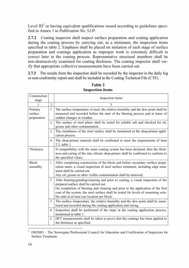
Level III2 or having equivalent qualifications issued according to guidelines speci-
fied in Annex 1 to Publication No. 51/P.
2.7.2 Coating inspector shall inspect surface preparation and coating application during the coating process by carrying out, as a minimum, the inspection items specified in table 2. Emphasis shall be placed on initiation of each stage of surface preparation and coatings application as improper work is extremely difficult to correct later in the coating process. Representative structural members shall be non-destructively examined for coating thickness. The coating inspector shall ver-ify that appropriate collective measurements have been carried out.
2.7.3 The results from the inspection shall be recorded by the inspector in the daily log or non-conformity report and shall be included in the Coating Technical File (CTF).
Table 2 Inspection items
Construction stage Inspection items
1 2 3 1 The surface temperature of steel, the relative humidity and the dew point shall be
measured and recorded before the start of the blasting process and at times of sudden changes in weather.
2 The surface of steel plates shall be tested for soluble salt and checked for oil, grease and other contamination.
3 The cleanliness of the steel surface shall be monitored in the shop-primer appli-cation process.
Primary surface preparation
4 The shop-primer material shall be confirmed to meet the requirements of item 2.3, table 1.
Thickness If compatibility with the main coating system has been declared, then the thick-ness and curing of the zinc silicate shop-primer shall be confirmed to conform to the specified values.
1 After completing construction of the block and before secondary surface prepa-ration starts, a visual inspection of steel surface treatment, including edge treat-ment shall be carried out. Any oil, grease or other visible contamination shall be removed.
2 After blasting/grinding/cleaning and prior to coating, a visual inspection of the prepared surface shall be carried out. On completion of blasting and cleaning and prior to the application of the first coat of the system, the steel surface shall be tested for levels of remaining solu-ble salts in at least one location per block.
3 The surface temperature, the relative humidity and the dew point shall be moni-tored and recorded during the coating application and curing.
4 Inspection shall be performed of the steps in the coating application process, mentioned in table 1.
Block assembly
5 DFT measurements shall be taken to prove that the coatings has been applied to the thickness as specified.
2 FROSIO – The Norwegian Professional Council for Education and Certification of Inspectors for
Surface Treatment.
16
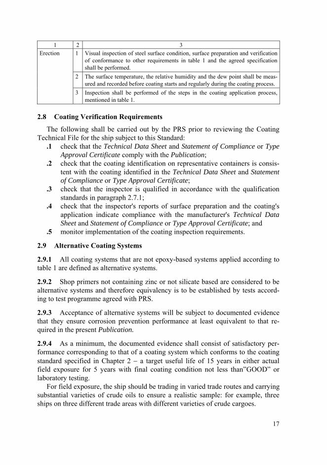
1 2 3 1 Visual inspection of steel surface condition, surface preparation and verification
of conformance to other requirements in table 1 and the agreed specification shall be performed.
2 The surface temperature, the relative humidity and the dew point shall be meas-ured and recorded before coating starts and regularly during the coating process.
Erection
3 Inspection shall be performed of the steps in the coating application process, mentioned in table 1.
2.8 Coating Verification Requirements
The following shall be carried out by the PRS prior to reviewing the Coating Technical File for the ship subject to this Standard:
.1 check that the Technical Data Sheet and Statement of Compliance or Type Approval Certificate comply with the Publication;
.2 check that the coating identification on representative containers is consis-tent with the coating identified in the Technical Data Sheet and Statement of Compliance or Type Approval Certificate;
.3 check that the inspector is qualified in accordance with the qualification standards in paragraph 2.7.1;
.4 check that the inspector's reports of surface preparation and the coating's application indicate compliance with the manufacturer's Technical Data Sheet and Statement of Compliance or Type Approval Certificate; and
.5 monitor implementation of the coating inspection requirements.
2.9 Alternative Coating Systems
2.9.1 All coating systems that are not epoxy-based systems applied according to table 1 are defined as alternative systems.
2.9.2 Shop primers not containing zinc or not silicate based are considered to be alternative systems and therefore equivalency is to be established by tests accord-ing to test programme agreed with PRS.
2.9.3 Acceptance of alternative systems will be subject to documented evidence that they ensure corrosion prevention performance at least equivalent to that re-quired in the present Publication.
2.9.4 As a minimum, the documented evidence shall consist of satisfactory per-formance corresponding to that of a coating system which conforms to the coating standard specified in Chapter 2 − a target useful life of 15 years in either actual field exposure for 5 years with final coating condition not less than”GOOD” or laboratory testing.
For field exposure, the ship should be trading in varied trade routes and carrying substantial varieties of crude oils to ensure a realistic sample: for example, three ships on three different trade areas with different varieties of crude cargoes.
17
2.10 Test procedures for coating qualification for cargo oil tanks of crude oil tankers
2.10.1 Details of the test procedures for cargo tank coatings for crude oil carriers are provided in Annex 1 to Resolution MSC.288(87).
3 PROCEDURE FOR COATING SYSTEM APPROVAL
Type Approval Certificate showing compliance with the PSPC section 5 shall be issued if the results of either method A+D, or B+D, or C+D are found satisfactory by PRS.
The Type Approval Certificate shall indicate the product and the shop primer tested. The certificate shall also indicate other type approved shop primers with which the product may be used which have undergone the crossover test in a labo-ratory meeting the requirements in paragraph 3.1.1.
The documents required to be submitted are identified in the following para-graphs, in addition for all type approvals the Technical Data Sheet showing all the information in accordance with PSPC 3.4.2.2 is required.
Winter type epoxy requires separate prequalification test including shop primer compatibility test according to PSPC Annex 1. Winter and summer type coating are considered different unless infrared (IR) identification and specific gravity (SG) demonstrates that they are the same.
3.1 Method A: Laboratory Test
3.1.1 Coating pre-qualification test shall be carried out by the test laboratory which is recognized by the PRS and the test laboratory shall meet the requirements specified in Publication No. 56/P – Procedural Requirements for Laboratories.
3.1.2 Results from satisfactory pre-qualification tests (PSPC Table 1, section 1.3 of the PSPC) of the coating system shall be documented according to the guide-lines specified in Annex 1 and Annex 2 to this Publication and submitted to PRS.
3.1.3 Type Approval tests shall be carried out for the epoxy-based system with the stated shop primer in accordance with the PSPC Annex 1. If the tests are satis-factory, a Type Approval Certificate will be issued to include both the epoxy and the shop primer. The Type Approval Certificate will allow the use of the epoxy either with the named shop primer or on bare prepared steel.
3.1.4 An epoxy-based system may be used with shop primers other than the one with which it was originally tested, provided that the other shop primers are ap-proved as part of a system, PSPC Table 1.2.3 and Table 1.3.2, and have been tested to Annex 1, Appendix 1, 1.7, which is known as the “Crossover Test”.
If the test or tests are satisfactory, a Type Approval Certificate will be issued. In this instance, the Type Approval Certificate will include the details of the epoxy and a list of all shop primers with which it has been tested that have passed these requirements.
18
The Type Approval Certificate will allow the use of the epoxy with all the named shop primers or on bare prepared steel.
3.1.5 Alternatively the epoxy can be tested without shop primer on bare prepared steel to the requirements of the PSPC Annex 1.
If the test or tests are satisfactory, a Type Approval Certificate will be issued. The Type Approval Certificate will just record the epoxy.
The certificate will allow the use of the epoxy on bare prepared steel only. If in addition, crossover tests are satisfactorily carried out with shop primers which are approved as part of a system, the Type Approval Certificate will include the details of shop primers which have satisfactorily passed the crossover test. In this instance the Type Approval Certificate will allow the use of the epoxy-based system with all the named shop primers or on bare prepared steel.
3.1.6 Type approval of a coating system is normally to be carried out in accor-dance with the PSPC Annex 1. PRS may, however, accept an equivalent laboratory test method comprised of a single test or number of tests combined as a test proce-dure, subject to the following acceptance requirements:
.1 The test method/programme shall be based on recognized national or inter-national standards, well established with proven experience.
.2 The equivalent test program shall adequately address the technical intent of the tests required in PSPC Annex 1.
.3 Test results of samples tested in accordance with the equivalent test meth-ods shall, wherever possible, be compared against the acceptance criteria of PSPC Annex 1. Where this is not possible due to the parameters of the equivalent test method used, the acceptance criteria of the equivalent test method standard shall be so selected as to provide the closest equivalent to those in PSPC Annex 1.
.4 Test laboratories shall be recognized by PRS and meet the requirements specified in Publication No. 56/P – Procedural Requirements for Labora-tories.
.5 Epoxy-based coating systems approved by such an equivalent test method shall be applied in the shipyard in accordance with all the surface prepara-tion and application requirements of the PSPC.
3.1.7 The Type Approval Certificate is invalid if the formulation of either the epoxy or the shop primer is changed. It is the responsibility of the manufacturer to inform class immediately of any changes to the formulation.
3.1.8 Approvals granted according to previous versions of PRS Publication No. 87/P, before the date of implementation of the latest revision, remain valid as stated in the respective certificate.
Renewal of certificates must be done in compliance with the latest version of PRS Publication No. 87/P.
19
3.2 Method B: 5 Years Field Exposure
3.2.1 Coating manufacturer’s records, which shall at least include the informa-tion indicated in 3.2.2, shall be examined to confirm coating system has 5 years field exposure, and the current product is the same as that being assessed.
3.2.2 Manufacturer’s records: – original application records, – original coating specification, – original technical data sheet, – current formulation’s unique identification (code or number), – if the mixing ratio of base and curing agent has changed, a statement from the
manufacturer confirming that the composition mixed product is the same as the original composition; this shall be accompanied by an explanation of the modi-fications made,
– current technical data sheet for the current production site, – SG and IR identification of original product, – SG and IR identification of the current product, – if original SG and IR cannot be provided then a statement from the manufac-
turer confirming the readings for the current product are the same as those of the original.
3.2.3 Either class survey records from PRS or a joint (coating manufacturer/ PRS) survey of all ballast tanks of a selected vessel is to be carried out for the pur-pose of verification of compliance with the requirements of paragraphs 3.2.1, 3.2.2 and 3.2.7.
The reporting of the coating condition in both cases shall be in accordance with Publication No. 39/P – Hull Surveys of Bulk Carriers and Publication No. 58/P – Hull Surveys of Double Hull Oil Tankers.
3.2.4 The selected vessel is to have ballast tanks in regular use, of which: – at least one tank is approximately 2000 m3 or more in capacity, – at least one tank shall be adjacent to a heated tank, and – at least one tank contains an underdeck exposed to the sun.
3.2.5 In the case that the selected vessel does not meet the requirements specified in 3.2.4, the limitations shall be clearly stated on the type approval certificate. For example, the coating cannot be used in tanks adjacent to heated tanks or underdeck or tanks with volume greater than the size surveyed.
3.2.6 In all cases of approval by Method B, the shop primer shall be removed prior to application of the approved epoxy-based system coating, unless it can be confirmed that the shop primer applied during construction, is identical in formula-tion to that applied in the selected vessel used as a basis of the approval.
20
3.2.7 All ballast tanks shall be in GOOD condition excluding mechanical dam-ages, without touch up or repair in the prior 5 years.
GOOD is defined as: condition with spot rusting on less than 3% of the area un-der consideration without visible failure of the coating. Rusting at edges or welds, must be on less than 20% of edges or welds in the area under consideration.
3.2.8 If the applied NDFT is greater than required by the PSPC, the applied NDFT will be the minimum to be applied during construction.
This will be reported prominently on the Type Approval Certificate.
3.2.9 If the results of the inspection are satisfactory, a Type Approval Certificate shall be issued to include both the epoxy-based system and the shop primer.
The Type Approval Certificate shall allow the use of the epoxy-based system ei-ther with the named shop primer or on bare prepared steel.
The Type Approval Certificate shall reference the inspection report which will also form part of the Coating Technical File.
3.2.10 The Type Approval Certificate is invalid if the formulation of either the epoxy-based system or the shop primer is changed. It is the responsibility of the manufacturer to inform class immediately of any changes to the formulation.
3.3 Method C: Existing Marintek B1 Approvals
3.3.1 Epoxy-based system Coatings Systems with existing satisfactory Marintek test reports minimum level B1 including relevant IR identification and SG, issued before 8 December 2006, can be accepted. If original SG and IR documentation can-not be provided, then a statement shall be provided by the manufacturer confirming that the readings for the current product are the same as those of the original.
3.3.2 The Marintek test report with IR and SG information shall be reviewed and if satisfactory, a Type Approval Certificate shall be issued. The certificate shall record the report reference and the shop primer used.
The Type Approval Certificate shall allow the use of the epoxy-based system ei-ther with the named shop primer, unless there is evidence to indicate that it is un-suitable, or on bare prepared steel.
3.3.3 The epoxy-based system approved by this method may be used with other shop primers if satisfactory crossover tests are carried out with shop primers which are approved as part of a system, see 3.1.4.
In this instance, the Type Approval Certificate will include the details of the ep-oxy-based system and a list of all shop primers which have passed these require-ments.
The Type Approval Certificate will allow the use of the epoxy-based system with all the named shop primers or on bare prepared steel.
21
3.3.4 Such coatings shall be applied in accordance with Table 1 of the PSPC rather than the application conditions used during the approval test which may differ from the PSPC, unless these are more stringent than Table 1 of the PSPC, for example if the NDFT is higher or high pressure water washing and/or sweep blast-ing of the shop primer is used. In such cases these limiting conditions shall be added to the type approval certificate and shall be followed during coating applica-tion in the shipyard.
3.3.5 The Type Approval Certificate is invalid if the formulation of either the epoxy-based system or the shop primer is changed.
It is the responsibility of the manufacturer to inform class immediately of any changes to the formulation.
3.4 Method D: Coating Manufacturer
3.4.1 The coating/shop primer manufacturer shall meet the requirements speci-fied in chapters 3, 4, 5, and 6 of Publication No. 56/P – Procedural Requirements for Laboratories and paragraphs 3.4.2 to 3.4.7 below, which shall be verified by PRS.
3.4.2 Coating Manufacturers: .1 Extent of Engagement – Production of coating systems in accordance with
PSPC and this Publication. .2 These requirements apply to both the main coating manufacturer and the
shop primer manufacturer where both coatings form part of the total sys-tem.
.3 The coating manufacturer should provide PRS with the following informa-tion: – a detailed list of the production facilities, – clearly stated names and location of raw material suppliers, – a detailed list of the test standards and equipment to be used (scope of
approval), – details of quality control procedures employed, – details of any sub-contracting agreements, – list of quality manuals, test procedures and instructions, records, etc. – copy of any relevant certificates with their issue number and/or date e.g.
Quality Management System certification. .4 Inspection and audit of the manufacturer’s facilities will be based on the
requirements of the PSPC. .5 With the exception of early ‘scale up’ from laboratory to full production,
adjustment outside the limitations listed in the QC instruction referred to below is not acceptable, unless justified by trials during the coating sys-tem’s development programme, or subsequent testing. Any such adjust-ments must be agreed by the formulating technical centre.
22
.6 If formulation adjustment is envisaged during the production process, the maximum allowable limits will be approved by the formulating technical centre and clearly stated in the QC working procedures.
.7 The manufacturer’s quality control system will ensure that all current pro-duction is the same formulation as that supplied for the Type Approval Cer-tificate. Formulation change is not permissible without testing in accor-dance with the test procedures in the PSPC and the issue of a Type Ap-proval Certificate by PRS.
.8 Batch records including all QC test results such as viscosity, specific grav-ity and airless spray characteristics will be accurately recorded. Details of any additions will also be included.
.9 Whenever possible, raw material supply and lot details for each coating batch will be traceable. Exceptions may be where bulk supply such as sol-vents and pre-dissolved solid epoxies are stored in tanks, in which case it may only be possible to record the supplier’s blend.
.10 Dates, batch numbers and quantities supplied to each coating contract will be clearly recorded.
3.4.3 All raw material supply must be accompanied by the supplier’s Certificate of Conformance. The certificate will include all requirements listed in the coating manufacturer’s QC system.
3.4.4 In the absence of a raw material supplier’s certificate of conformance, the coating manufacturer must verify conformance to all requirements listed in the coating manufacturer’s QC system.
3.4.5 Drums must be clearly marked with the details as described on the Type Approval Certificate.
3.4.6 Product Technical Data Sheets must comply with all the PSPC requirements. The QC system will ensure that all Product Technical Data Sheets are current.
3.4.7 QC procedures of the originating technical centre will verify that all pro-duction units comply with the above stipulations and that each raw material supply is approved by the technical centre.
3.4.8 In the case that a manufacturer wishes to have products which are manufac-tured in different locations under the same name, IR identification and SG shall be used to demonstrate that they are the same coating, or individual approval tests will be required for the paint manufactured in each location.
3.4.9 The Type Approval Certificate is invalid if the formulation of either the epoxy-based system or the shop primer is changed. It is the responsibility of the manufacturer to inform class immediately of any changes to the formulation.
Failure to inform class of an alteration to the formulation will lead to cancella-tion of the certificates for that manufacturer’s products.
23
4 PROCEDURE FOR ASSESSMENT OF COATING INSPECTORS’ QUALIFICATIONS
4.1 Coating inspectors required to carry out inspections in accordance with the PSPC section 6 shall be certified to NACE Coating Inspector Level 2, FROSIO Inspector Level III, or an equivalent qualification. Equivalent qualifications are described in 4.3 below.
4.2 However, only coating inspectors with at least 2 years relevant coating in-spector experience and certified to NACE Coating Inspector Level 2 or FROSIO Inspector Level III, or with an equivalent qualification, can write and/or authorise procedures, or decide upon corrective actions to overcome non-compliances.
4.3 Equivalent Qualification
4.3.1 Equivalent qualification is the successful completion, as determined by course tutor, of an approved course.
4.3.1.1 The course tutors shall be qualified with at least 2 years relevant experi-ence and qualified to NACE Coating Inspector Level 2 or FROSIO Inspector Level III, or with an equivalent qualification.
4.3.1.2 Approved Course: A course that has a syllabus based on the issues asso-ciated with the PSPC including the following: – health environment and safety, – corrosion, – materials and design, – international standards referenced in PSPC, – curing mechanisms, – role of inspector, – test instruments, – inspection procedures, – coating specification, – application procedures, – coating failures, – pre-job conference, – MSDS and product data sheet review, – coating technical file, – surface preparation, – dehumidification, – waterjetting, – coating types and inspection criteria, – specialized application equipment, – use of inspection procedures for destructive testing and non-destructive testing
instruments, – inspection instruments and test methods,
24
– coating inspection techniques, – cathodic protection, – practical exercises, case studies.
Examples of approved courses may be internal courses run by the coating manufacturers or shipyards etc.
4.3.1.3 Such a course shall have an acceptable measurement of performance, such as an examination with both theoretical and practical elements. The course and examination shall be approved by PRS.
4.3.2 Equivalent qualification arising from practical experience: An individual may be qualified without attending a course where it can be shown that the indi-vidual: – has a minimum of 5-years practical work experience as a coating inspector of
ballast tanks during new construction within the last 10 years, and – has successfully completed the examination given in 4.3.1.3.
4.4 Assistant Inspectors
4.4.1 If the coating inspector requires assistance from other persons to do the part of the inspections under the coating inspector’s supervision, those persons shall be trained to the coating inspector’s satisfaction.
4.4.2 Such training should be recorded and endorsed either by the inspector, the yard's training organisation or inspection equipment manufacturer to confirm com-petence in using the measuring equipment and confirm knowledge of the meas-urements required by the PSPC.
4.4.3 Training records shall be available for verification if required.
5 PROCEDURE FOR INSPECTION AGREEMENT
5.1 Inspection of surface preparation and coating processes agreement shall be signed by shipyard, shipowner and coating manufacturer and shall be presented by the shipyard to PRS for review prior to commencement of any coating work on any stage of a new building and as a minimum shall comply with the PSPC.
5.2 To facilitate the review, the following from the CTF, shall be available: .1 Coating specification including selection of areas (spaces) to be coated, se-
lection of coating system, surface preparation and coating process. .2 Statement of Compliance or Type Approval of the coating system.
5.3 The agreement shall be included in the CTF and shall at least cover: .1 Inspection process, including scope of inspection, who carries out the in-
spection, the qualifications of the coating inspector(s) and appointment of a qualified coating inspector (responsible for verifying that the coating is
25
applied in accordance with the PSPC). Where more than one coating in-spector will be used, then their areas of responsibility shall be identified. (For example multiple construction sites).
.2 Language to be used for documentation.
5.4 Any deviations in the procedure relative to the PSPC noted during the review shall be raised with the shipyard, which is responsible for identifying and imple-menting the corrective actions.
5.5 The Certificate of Class shall not be issued until all required corrective ac-tions have been closed out to the satisfaction of PRS.
6 PROCEDURE FOR VERIFICATION OF APPLICATION OF THE PSPC
6.1 The verification requirements of section 7 of the PSPC shall be carried out by PRS.
6.2 Monitoring implementation of the coating inspection requirements, as called for in section 7.5 of the PSPC means checking, on a sampling basis, that the in-spectors are using the correct equipment, techniques and reporting methods as de-scribed in the inspection procedures reviewed by PRS.
6.3 Any deviations found under 6.2 shall be raised initially with the coating in-spector, who is responsible for identifying and implementing the corrective actions.
6.4 In the event that corrective actions are not acceptable to PRS or in the event that corrective actions are not closed out then the shipyard shall be informed.
6.5 The Certificate of Class shall not be issued until all required corrective ac-tions have been closed out to the satisfaction of PRS.
7 PROCEDURE FOR COATING TECHNICAL FILE REVIEW
7.1 The shipyard is responsible for compiling the Coating Technical File (CTF) either in paper or electronic format, or a combination of the two.
7.2 The CTF is to contain all the information required by the PSPC section 3.4 and the inspection of surface preparation and the coating processes agreement.
7.3 The CTF shall be reviewed for content in accordance with the PSPC section 3.4.2.
7.4 Any deviations found under 7.3 shall be raised with the shipyard, which is responsible for identifying and implementing the corrective actions.
7.5 The Certificate of Class shall not be issued until all required corrective ac-tions have been closed out to the satisfaction of PRS.
26
8 PROCEDURE FOR REVIEW OF QUALITY CONTROL OF AUTOMATED SHOP PRIMER PLANTS
8.1 It is recognised that the inspection requirements of section 6.2 of the PSPC may be difficult to apply to an automated shop primer plant and a Quality Control approach would be a more practical way of enabling compliance with the require-ments of PSPC.
8.2 As required in PSPC, it is the responsibility of the coating inspector to con-firm that the quality control procedures are ensuring compliance with PSPC.
8.3 When reviewing the Quality Control for automated shop primer plants, the following procedures should be included:
.1 Procedures for management of the blasting grit including measurement of salt and contamination.
.2 Procedures recording the following: steel surface temperature, relative hu-midity, dewpoint.
.3 Procedures for controlling or monitoring surface cleanliness, surface pro-file, oil, grease, dust and other contamination.
.4 Procedures for recording/measuring soluble salts.
.5 Procedures for verifying that thickness and curing of the shop primer con-forms to the values specified in the Technical Specification.
9 PROCEDURE FOR REVIEW OF COATING TECHNICAL SPECIFICATIONS
9.1 The Coating Technical Specifications should be provided by the shipyard in accordance with the requirements of PSPC detailing all the requirements of Table 1 of the PSPC.
9.2 The Coating Technical Specifications should contain the type of coating sys-tem, steel preparation, surface preparation, surface cleanliness, environmental con-ditions, application procedure, acceptance criteria and inspection.
10 CATHODIC PROTECTION ON OIL TANKERS
10.1 Impressed current systems are not permitted in oil cargo tanks.
10.2 Magnesium or magnesium alloy anodes are not permitted in oil cargo tanks and tanks adjacent to cargo tanks.
10.3 Aluminium anodes are only permitted in cargo tanks and tanks adjacent to cargo tanks in locations where the potential energy does not exceed 270 J. The height of the anode shall be measured from the bottom of the tank to the centre of the anode, and its weight shall be taken as the weight of the anode as fitted, includ-ing the fitting devices and inserts. However, where aluminium anodes are located
27
on horizontal surfaces such as bulkhead girders and stringers not less than 1 m wide and fitted with an upstanding flange or face flat projecting not less than 75 mm above the horizontal surface, the height of the anode may be measured from this surface. Aluminium anodes shall not be located under tank hatches or openings for tank cleaning, the so-called Butterworth openings (in order to avoid any metal parts falling on the fitted anodes), unless protected by adjacent structure.
10.4 There is no restriction on the positioning of zinc anodes.
10.5 The anodes shall have steel cores and these shall be sufficiently rigid to avoid resonance in the anode support and be so designed that they retain the anode even when it is wasted.
10.6 The steel inserts shall be attached to the structure by means of a continuous weld of adequate section. Alternatively they may be attached to the separate sup-ports by bolting, provided a minimum of two bolts with locknuts are used.
Other approved mechanical means of clamping may be accepted by PRS.
10.7 The supports at each end of an anode shall be not attached to separate items which are likely to move independently.
10.8 When anode inserts or supports are welded to the structure, they shall be so arranged that the welds are clear of stress raisers.
28
Annex 1 Model Report for IMO Resolution MSC.215(82) Annex 1
“Test Procedures for Coating Qualification”:
Example Coating Producer Ballast Tank Coating Test
of 2 * 160 μm Example Epoxy Paint on Example Shop Primer
1 Summary The coating system, 2 * 160 μm Example Epoxy Paint from Example Coating
Producer, applied to Example zinc silicate shop primed panels has been tested in accordance with the PSPC. The coating was applied after 2 months’ weathering of the shop primer.
The results from the testing show that the Example Epoxy Paint from Example Coating Producer has fulfilled all the requirements specified in the PSPC.
2 Scope of Work The following work and tests have been performed:
– identification of the coating system, – film thickness measurements and pin hole detection on panels before testing, – 180 days testing in condensation, – 180 days testing in wave tank, – 180 days testing in heating cabinet, – evaluation of results after testing, including blister detection, undercutting from
scribe, adhesion and coating flexibility, – evaluation of cathodic protection during testing (wave tank).
3 Work Performed Prior to Exposure
3.1 Identification
The coating system was identified by infrared scanning (by means of a ….(name and model of the instrument)), and by determination of specific gravity (according to ISO 2811-1) by means of a pyknometer (name and model of the instrument).
3.2 Surface preparation
Surface preparation was performed in accordance with the data specified in ta-ble B-1, Appendix B.
3.3 Application
3.3.1 Application Procedure Example zinc silicate shop primer was applied to the blast cleaned panels accord-
ing to the data given in table 2. The shop primed panels were then exposed outdoor for 2 months. The environmental data for the exposure period are specified in Ap-pendix A.
29
Two coats (specified dry film thickness 160 μm per coat) of Example Epoxy Paint were applied to the weathered and cleaned zinc silicate shop primed panel. The application data are specified in table B-2 Appendix B.
3.3.2 Coding
The panel were coded as shown in figure B-1 in Appendix B.
3.4 Dry Film Thickness
The dry film thickness measurements were performed by means of (name and model of the instrument) dry film thickness unit before testing. Templates, as shown in figure B-2 in Appendix B, were used for the measurements. The results from the measurements are given in table B-3 in Appendix B.
3.5 Pinhole Detection
Pinhole detection was performed on the coated test panel before testing. The de-tection was performed by means of (name and model of the instrument) pinhole detector at 90 volts.
4 Exposure
Tests were performed according to the PSPC. The exposure started on 02.11.07 and ended on 14.06.08.
5 Tests Performed After Exposure
Evaluation of blisters and rust, adhesion, undercutting from scribe and flexibility was performed according to specifications and standards referred to in the PSPC.
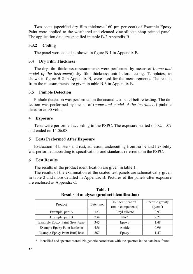
6 Test Results
The results of the product identification are given in table 1. The results of the examination of the coated test panels are schematically given
in table 2 and more detailed in Appendix B. Pictures of the panels after exposure are enclosed as Appendix C.
Table 1 Results of analyses (product identification)
Product Batch no. IR identification
(main components) Specific gravity
(g/cm3) Example, part A 123 Ethyl silicate 0.93 Example, part B 234 NA* 2.21
Example Epoxy Paint Grey, base 345 Epoxy 1.48 Example Epoxy Paint hardener 456 Amide 0.96
Example Epoxy Paint Buff, base 567 Epoxy 1.47
* Identified and spectres stored. No generic correlation with the spectres in the data base found.
30
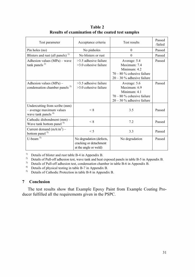
Table 2 Results of examination of the coated test samples
Test parameter Acceptance criteria Test results Passed /failed
Pin holes (no) No pinholes 0 Passed Blisters and rust (all panels) 1) No blisters or rust 0 Passed Adhesion values (MPa) – wave tank panels 2)
>3.5 adhesive failure >3.0 cohesive failure
Average: 5.4 Maximum: 7.4 Minimum: 4.2
70 – 80 % cohesive failure 20 – 30 % adhesive failure
Passed
Adhesion values (MPa) –condensation chamber panels 3)
>3.5 adhesive failure >3.0 cohesive failure
Average: 5.6 Maximum: 6.9 Minimum: 4.1
70 – 80 % cohesive failure 20 – 30 % adhesive failure
Passed
Undercutting from scribe (mm) – average maximum values wave tank panels 4)
< 8 3.5 Passed
Cathodic disbondment (mm) – Wave tank bottom panel 5) < 8 7.2 Passed
Current demand (mA/m2) – bottom panel 5) < 5 3.3 Passed
U-beam 5) No degradation (defects, cracking or detachment at the angle or weld)
No degradation Passed
1) Details of blister and rust table B-4 in Appendix B. 2) Details of Pull-off adhesion test, wave tank and heat exposed panels in table B-5 in Appendix B. 3) Details of Pull-off adhesion test, condensation chamber in table B-6 in Appendix B. 4) Details of physical testing in table B-7 in Appendix B. 5) Details of Cathodic Protection in table B-8 in Appendix B.
7 Conclusion
The test results show that Example Epoxy Paint from Example Coating Pro-ducer fulfilled all the requirements given in the PSPC.
31
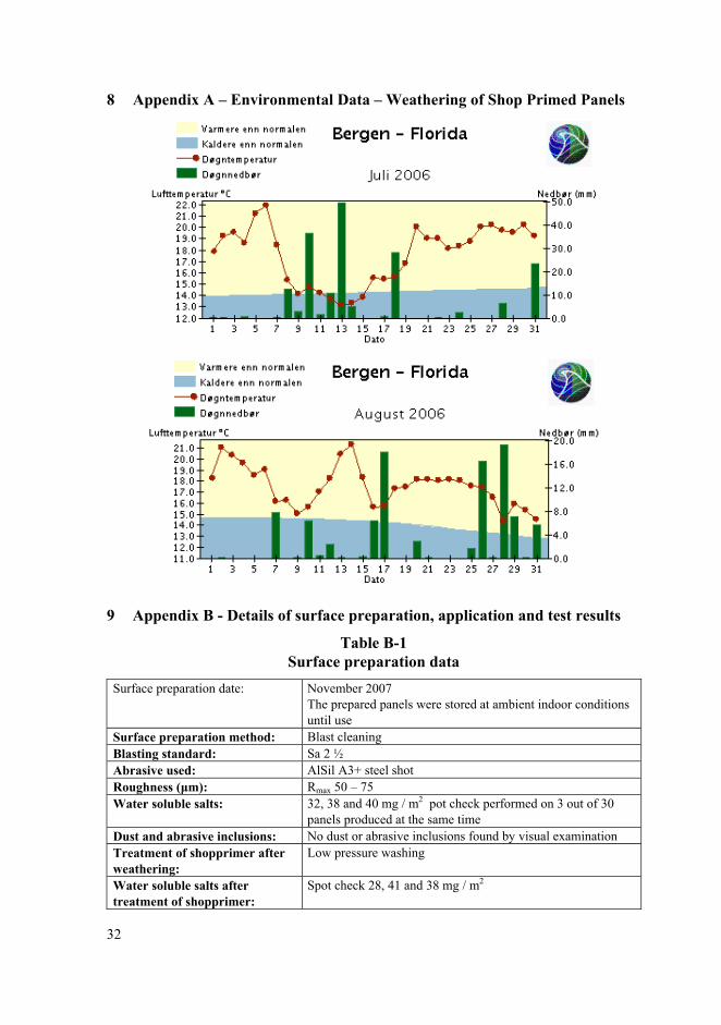
8 Appendix A – Environmental Data – Weathering of Shop Primed Panels
9 Appendix B - Details of surface preparation, application and test results
Table B-1 Surface preparation data
Surface preparation date: November 2007 The prepared panels were stored at ambient indoor conditions until use
Surface preparation method: Blast cleaning Blasting standard: Sa 2 ½ Abrasive used: AlSil A3+ steel shot Roughness (μm): Rmax 50 – 75 Water soluble salts: 32, 38 and 40 mg / m2 pot check performed on 3 out of 30
panels produced at the same time Dust and abrasive inclusions: No dust or abrasive inclusions found by visual examination Treatment of shopprimer after weathering:
Low pressure washing
Water soluble salts after treatment of shopprimer:
Spot check 28, 41 and 38 mg / m2
32
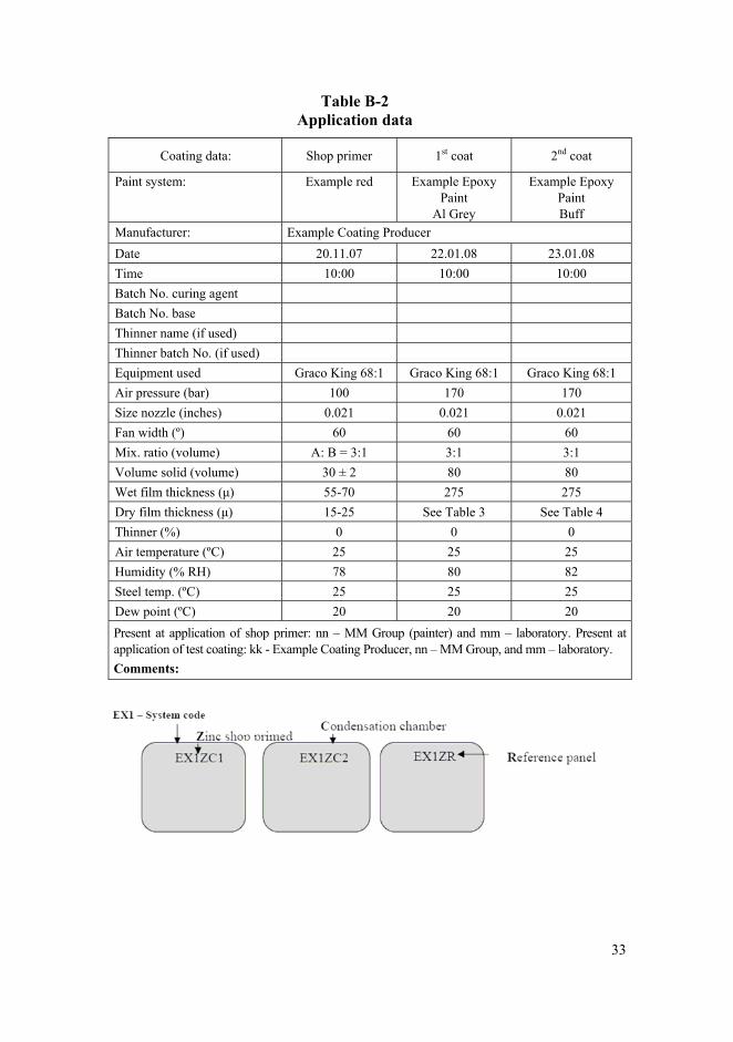
Table B-2 Application data
Coating data: Shop primer 1st coat 2nd coat
Paint system:
Example red Example Epoxy Paint
Al Grey
Example Epoxy Paint Buff
Manufacturer: Example Coating Producer Date 20.11.07 22.01.08 23.01.08 Time 10:00 10:00 10:00 Batch No. curing agent Batch No. base Thinner name (if used) Thinner batch No. (if used) Equipment used Graco King 68:1 Graco King 68:1 Graco King 68:1 Air pressure (bar) 100 170 170 Size nozzle (inches) 0.021 0.021 0.021 Fan width (º) 60 60 60 Mix. ratio (volume) A: B = 3:1 3:1 3:1 Volume solid (volume) 30 ± 2 80 80 Wet film thickness (μ) 55-70 275 275 Dry film thickness (μ) 15-25 See Table 3 See Table 4 Thinner (%) 0 0 0 Air temperature (ºC) 25 25 25 Humidity (% RH) 78 80 82 Steel temp. (ºC) 25 25 25 Dew point (ºC) 20 20 20 Present at application of shop primer: nn – MM Group (painter) and mm – laboratory. Present at application of test coating: kk - Example Coating Producer, nn – MM Group, and mm – laboratory. Comments:
33
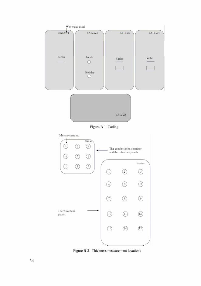
Figure B-1 Coding
Figure B-2 Thickness measurement locations
34
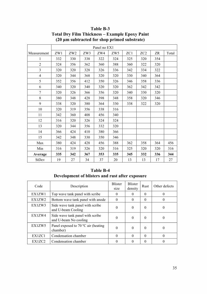
Table B-3 Total Dry Film Thickness – Example Epoxy Paint
(20 μm subtracted for shop primed substrate)
Panel no EX1 Measurement ZW1 ZW2 ZW3 ZW4 ZW5 ZC1 ZC2 ZR Total
1 332 330 338 322 324 325 320 354 2 324 356 362 360 388 360 322 320 3 320 320 328 326 336 342 334 322 4 320 344 368 320 320 330 340 364 5 352 356 412 350 326 346 358 336 6 340 320 340 320 320 362 342 342 7 320 326 366 356 320 340 330 320 8 380 348 428 398 348 358 320 346 9 338 320 380 364 330 338 322 320
10 320 319 356 338 316 11 342 360 408 456 340 12 316 320 326 324 324 13 320 344 356 332 320 14 366 424 410 380 366 15 342 348 330 350 346
Max 380 424 428 456 388 362 358 364 456 Min 316 319 326 320 316 325 320 320 316
Average 335 342 367 353 335 345 332 336 344 StDev 19 27 34 37 20 13 13 17 27
Table B-4 Development of blisters and rust after exposure
Code Description Blister size
Blister density Rust Other defects
EX1ZW1 Top wave tank panel with scribe 0 0 0 0 EX1ZW2 Bottom wave tank panel with anode 0 0 0 0 EX1ZW3 Side wave tank panel with scribe
and U-beam Cooling 0 0 0 0
EX1ZW4 Side wave tank panel with scribe and U-beam No cooling 0 0 0 0
EX1ZW5 Panel exposed to 70 ºC air (heating chamber) 0 0 0 0
EX1ZC1 Condensation chamber 0 0 0 0 EX1ZC2 Condensation chamber 0 0 0 0
35
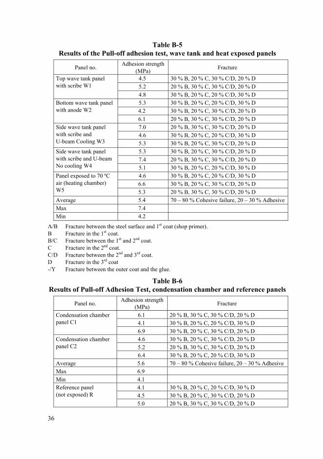
Table B-5 Results of the Pull-off adhesion test, wave tank and heat exposed panels
Panel no. Adhesion strength (MPa) Fracture
4.5 30 % B, 20 % C, 30 % C/D, 20 % D 5.2 20 % B, 30 % C, 30 % C/D, 20 % D
Top wave tank panel with scribe W1
4.8 30 % B, 20 % C, 20 % C/D, 30 % D 5.3 30 % B, 20 % C, 20 % C/D, 30 % D 4.2 30 % B, 20 % C, 30 % C/D, 20 % D
Bottom wave tank panel with anode W2
6.1 20 % B, 30 % C, 30 % C/D, 20 % D 7.0 20 % B, 30 % C, 30 % C/D, 20 % D 4.6 30 % B, 20 % C, 20 % C/D, 30 % D
Side wave tank panel with scribe and U-beam Cooling W3 5.3 30 % B, 20 % C, 30 % C/D, 20 % D
5.3 30 % B, 20 % C, 30 % C/D, 20 % D 7.4 20 % B, 30 % C, 30 % C/D, 20 % D
Side wave tank panel with scribe and U-beamNo cooling W4 5.1 30 % B, 20 % C, 20 % C/D, 30 % D
4.6 30 % B, 20 % C, 20 % C/D, 30 % D 6.6 30 % B, 20 % C, 30 % C/D, 20 % D
Panel exposed to 70 ºC air (heating chamber) W5 5.3 20 % B, 30 % C, 30 % C/D, 20 % D Average 5.4 70 – 80 % Cohesive failure, 20 – 30 % Adhesive Max 7.4 Min 4.2
A/B Fracture between the steel surface and 1st coat (shop primer). B Fracture in the 1st coat. B/C Fracture between the 1st and 2nd coat. C Fracture in the 2nd coat. C/D Fracture between the 2nd and 3rd coat. D Fracture in the 3rd coat -/Y Fracture between the outer coat and the glue.
Table B-6 Results of Pull-off Adhesion Test, condensation chamber and reference panels
Panel no. Adhesion strength (MPa) Fracture
6.1 20 % B, 30 % C, 30 % C/D, 20 % D 4.1 30 % B, 20 % C, 20 % C/D, 30 % D
Condensation chamber panel C1
6.9 30 % B, 20 % C, 30 % C/D, 20 % D 4.6 30 % B, 20 % C, 30 % C/D, 20 % D 5.2 20 % B, 30 % C, 30 % C/D, 20 % D
Condensation chamber panel C2
6.4 30 % B, 20 % C, 20 % C/D, 30 % D Average 5.6 70 – 80 % Cohesive failure, 20 – 30 % Adhesive Max 6.9 Min 4.1
4.1 30 % B, 20 % C, 20 % C/D, 30 % D 4.5 30 % B, 20 % C, 30 % C/D, 20 % D
Reference panel (not exposed) R
5.0 20 % B, 30 % C, 30 % C/D, 20 % D
36
A/B Fracture between the steel surface and 1st coat (shop primer). B Fracture in the 1st coat. B/C Fracture between the 1st and 2nd coat. C Fracture in the 2nd coat. C/D Fracture between the 2nd and 3rd coat. D Fracture in the 3rd coat -/Y Fracture between the outer coat and the glue.
Table B-7 Results of physical testing
Panel Undercutting from scribe (mm)* Flexibility** Comment
Top wave tank panel EX1ZW1 5.7 150 mm ≤ 2 % elongation
Cooled side wave tank panel EX1ZW3 2.2 NA
Not cooled side wave tank panel EX1ZW4 2.6 NA
Average 3.5 Reference panel (not exposed) EX1ZR Not applicable 75 mm ≤ 4 % elongation
* Evaluated by scraping with knife. ** Flexibility1) modified according to panel thickness (3 mm steel, 300 μm coating, 150 mm cylin-
drical mandrel gives 2% elongation) for information only; 1) Reference standards: ASTM D4145:1983. Standard Test Method for Coating Flexibility of Pre-
painted Sheet.
Undercutting from scribe: “Rinse the test panel with fresh tap water immediately after exposure, blowing off residues of wa-
ter from the surface using compressed air if necessary, and inspect for visible changes. Carefully remove any loose coating using a knife blade held at an angle, positioning the blade at the coat-ing/substrate interface and lifting the coating away from the substrate.” (Acc. to ISO 4628-8:2005, section 5.3.1.)
“Calculate the degree of delamination d, in millimetre using the following equation d=(d1-w)/2, where d1 is the mean overall width of the zone of delamination, in millimetres; w is the width of the original scribe, in millimetres.” (Acc. to ISO 4628-8:2005, section 6.1.)
“Calculate the degree of corrosion c, in millimetre using the equation c=(wc-w)/2 where wc is the mean overall width of the zone of corrosion, in millimetres; w is the width of the original scribe, in millimetres.” (Acc. to ISO 4628-8:2005, section 6.2.)
Additionally interpretation of PSPC: Undercutting from scribe can be either corrosion of the steel substrate or delamination between the shop primer and the epoxy coating (compability test). For PSPC maximum width is used (MSC.215(82), Appendix 1, section 2.2.6 and not mean overall width as in the ISO standard. The average of the three maximum records (three panels with scribe) is used for acceptance and shall be less than 8 mm for epoxy based systems to be acceptable. Cohesive adhe-sion failure in the shop primer shall not be included as part of the delamination.
37
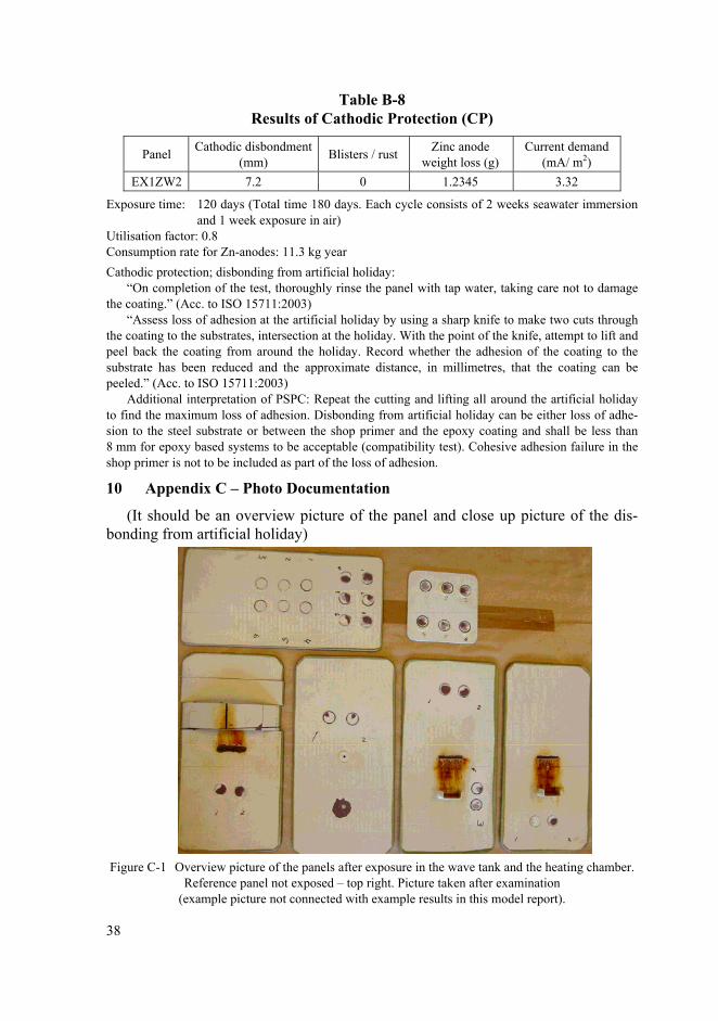
Table B-8 Results of Cathodic Protection (CP)
Panel Cathodic disbondment (mm) Blisters / rust Zinc anode
weight loss (g) Current demand
(mA/ m2) EX1ZW2 7.2 0 1.2345 3.32
Exposure time: 120 days (Total time 180 days. Each cycle consists of 2 weeks seawater immersion and 1 week exposure in air)
Utilisation factor: 0.8 Consumption rate for Zn-anodes: 11.3 kg year Cathodic protection; disbonding from artificial holiday:
“On completion of the test, thoroughly rinse the panel with tap water, taking care not to damage the coating.” (Acc. to ISO 15711:2003)
“Assess loss of adhesion at the artificial holiday by using a sharp knife to make two cuts through the coating to the substrates, intersection at the holiday. With the point of the knife, attempt to lift and peel back the coating from around the holiday. Record whether the adhesion of the coating to the substrate has been reduced and the approximate distance, in millimetres, that the coating can be peeled.” (Acc. to ISO 15711:2003)
Additional interpretation of PSPC: Repeat the cutting and lifting all around the artificial holiday to find the maximum loss of adhesion. Disbonding from artificial holiday can be either loss of adhe-sion to the steel substrate or between the shop primer and the epoxy coating and shall be less than 8 mm for epoxy based systems to be acceptable (compatibility test). Cohesive adhesion failure in the shop primer is not to be included as part of the loss of adhesion.
10 Appendix C – Photo Documentation
(It should be an overview picture of the panel and close up picture of the dis-bonding from artificial holiday)
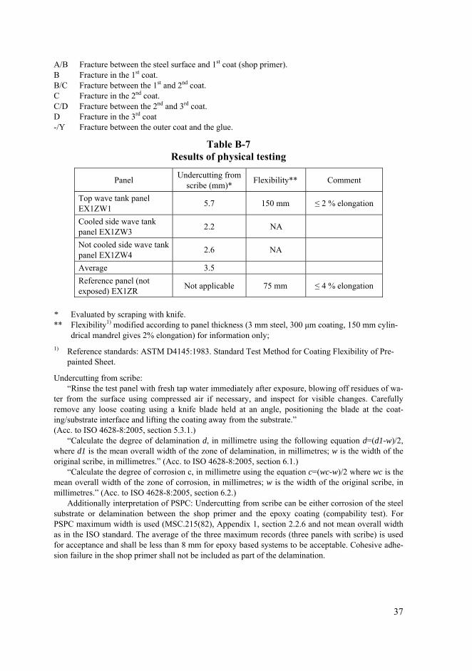
Figure C-1 Overview picture of the panels after exposure in the wave tank and the heating chamber.
Reference panel not exposed – top right. Picture taken after examination (example picture not connected with example results in this model report).
38
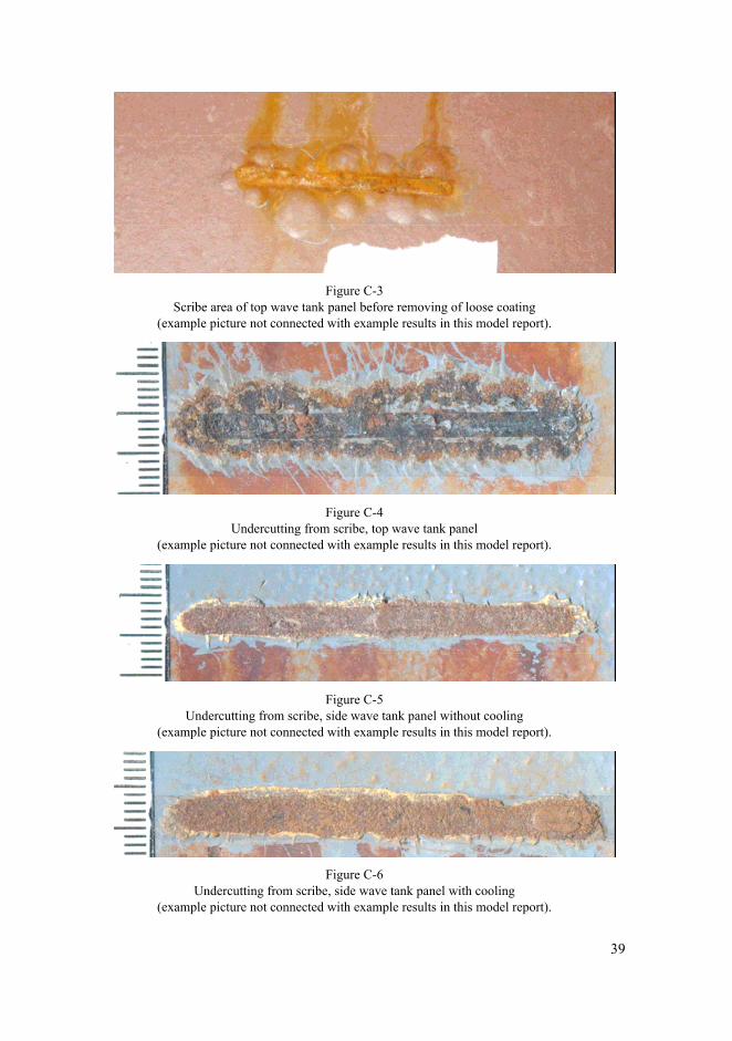
Figure C-3
Scribe area of top wave tank panel before removing of loose coating (example picture not connected with example results in this model report).
Figure C-4
Undercutting from scribe, top wave tank panel (example picture not connected with example results in this model report).
Figure C-5
Undercutting from scribe, side wave tank panel without cooling (example picture not connected with example results in this model report).
Figure C-6
Undercutting from scribe, side wave tank panel with cooling (example picture not connected with example results in this model report).
39
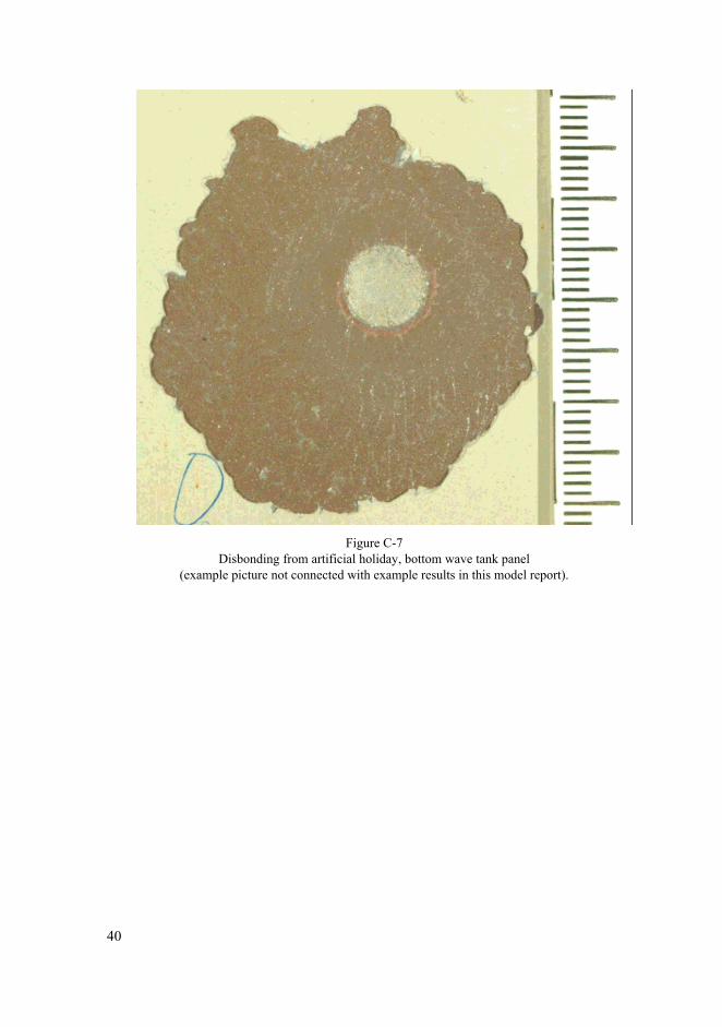
Figure C-7
Disbonding from artificial holiday, bottom wave tank panel (example picture not connected with example results in this model report).
40
Annex 2 Model Report for IMO Resolution MSC.215(82) Annex 1
“Test Procedures for Coating Qualification”, Section 1.7 – Crossover Test: Example Coating Producer
Ballast Tank Coating Test of 2 * 160 μm Example Epoxy Paint on Example Shop Primer
1 Summary
The coating system, 2 * 160 μm Example Epoxy Paint from Example Coating Producer, applied to Example zinc silicate shop primed panels has been tested in accordance with the PSPC, Section 1.7 of Appendix 1 to Annex 1 without wave movement (crossover test). The coating was applied after 2 months’ weathering of the shop primer.
The results from the testing show that the Example Epoxy Paint from Example Coating Producer has fulfilled all the requirements given in the PSPC.
2 Scope of Work
The following work and tests have been performed: – identification of the coating system, – film thickness measurements and pin hole detection on panels before testing, – 180 days testing in wave tank conditions, but without wave movement, – evaluation of results after testing, including blister detection, disbonding from
artificial holiday and adhesion.
3 Work Performed Prior to Exposure
3.1 Identification
The coating system was identified by infrared scanning (by means of ….(name and model of the instrument)), and by determination of specific gravity (according to ISO 2811-1) by means of a pyknometer (name and model of the instrument).
3.2 Surface Preparation
Surface preparation was performed according to the data specified in table B-1 Appendix B.
3.3 Application
3.3.1 Application Procedure Example zinc silicate shop primer was applied to the blast cleaned panels ac-
cording to the data given in table 2. The shop primed panel were then exposed out-door for 2 months. The environmental data for the exposure period is given in Ap-pendix A.
41
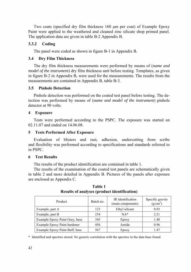
Two coats (specified dry film thickness 160 μm per coat) of Example Epoxy Paint were applied to the weathered and cleaned zinc silicate shop primed panel. The application data are given in table B-2 Appendix B.
3.3.2 Coding
The panel were coded as shown in figure B-1 in Appendix B.
3.4 Dry Film Thickness
The dry film thickness measurements were performed by means of (name and model of the instrument) dry film thickness unit before testing. Templates, as given in figure B-2 in Appendix B, were used for the measurements. The results from the measurements are contained in Appendix B, table B-3.
3.5 Pinhole Detection
Pinhole detection was performed on the coated test panel before testing. The de-tection was performed by means of (name and model of the instrument) pinhole detector at 90 volts.
4 Exposure
Tests were performed according to the PSPC. The exposure was started on 02.11.07 and ended on 14.06.08.
5 Tests Performed After Exposure
Evaluation of blisters and rust, adhesion, undercutting from scribe and flexibility was performed according to specifications and standards referred to in PSPC.
6 Test Results
The results of the product identification are contained in table 1. The results of the examination of the coated test panels are schematically given
in table 2 and more detailed in Appendix B. Pictures of the panels after exposure are enclosed as Appendix C.
Table 1 Results of analyses (product identification)
Product Batch no. IR identification (main components)
Specific gravity (g/cm3)
Example, part A 123 Ethyl silicate 0.93 Example, part B 234 NA* 2.21 Example Epoxy Paint Grey, base 345 Epoxy 1.48 Example Epoxy Paint hardener 456 Amide 0.96 Example Epoxy Paint Buff, base 567 Epoxy 1.47
* Identified and spectres stored. No generic correlation with the spectres in the data base found.
42
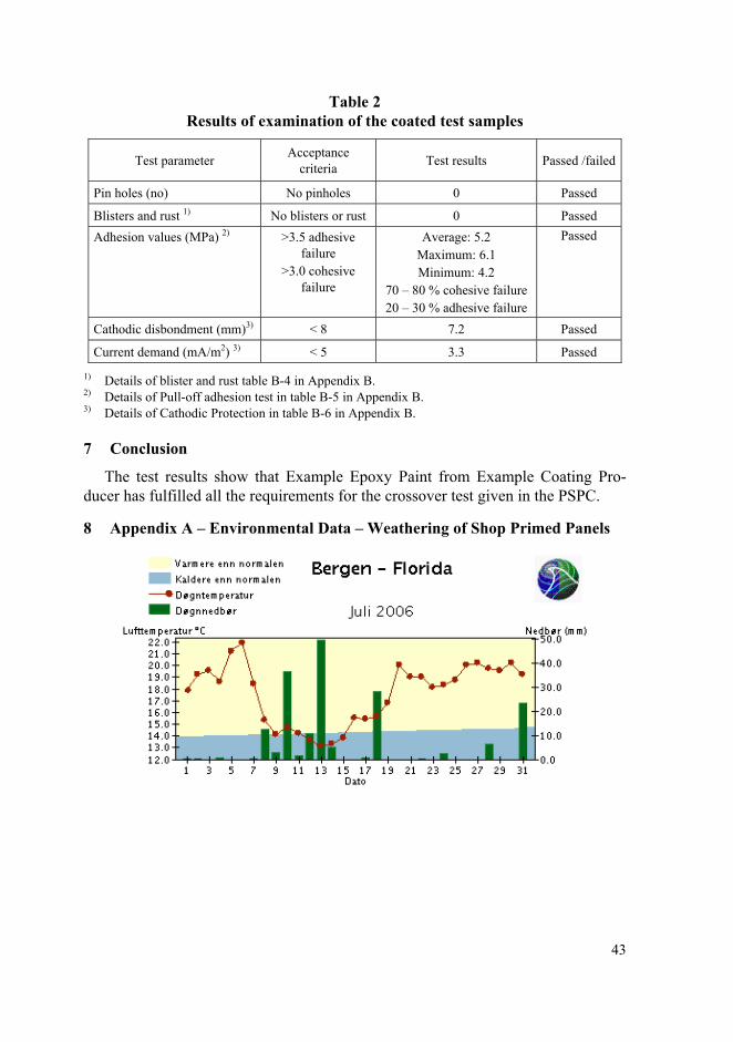
Table 2 Results of examination of the coated test samples
Test parameter Acceptance criteria Test results Passed /failed
Pin holes (no) No pinholes 0 Passed
Blisters and rust 1) No blisters or rust 0 Passed Adhesion values (MPa) 2) >3.5 adhesive
failure >3.0 cohesive
failure
Average: 5.2 Maximum: 6.1 Minimum: 4.2
70 – 80 % cohesive failure 20 – 30 % adhesive failure
Passed
Cathodic disbondment (mm)3) < 8 7.2 Passed
Current demand (mA/m2) 3) < 5 3.3 Passed
1) Details of blister and rust table B-4 in Appendix B. 2) Details of Pull-off adhesion test in table B-5 in Appendix B. 3) Details of Cathodic Protection in table B-6 in Appendix B.
7 Conclusion
The test results show that Example Epoxy Paint from Example Coating Pro-ducer has fulfilled all the requirements for the crossover test given in the PSPC.
8 Appendix A – Environmental Data – Weathering of Shop Primed Panels
43
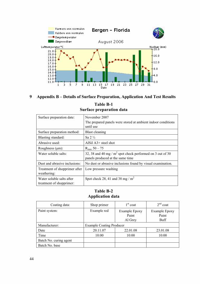
9 Appendix B – Details of Surface Preparation, Application And Test Results
Table B-1 Surface preparation data
Surface preparation date: November 2007 The prepared panels were stored at ambient indoor conditions until use
Surface preparation method: Blast cleaning Blasting standard: Sa 2 ½ Abrasive used: AlSil A3+ steel shot Roughness (μm): Rmax 50 – 75 Water soluble salts: 32, 38 and 40 mg / m2 spot check performed on 3 out of 30
panels produced at the same time Dust and abrasive inclusions: No dust or abrasive inclusions found by visual examination. Treatment of shopprimer after weathering:
Low pressure washing
Water soluble salts after treatment of shopprimer:
Spot check 28, 41 and 38 mg / m2
Table B-2 Application data
Coating data: Shop primer 1st coat 2nd coat Paint system:
Example red Example Epoxy Paint
Al Grey
Example Epoxy Paint Buff
Manufacturer: Example Coating Producer Date 20.11.07 22.01.08 23.01.08 Time 10:00 10:00 10:00 Batch No. curing agent Batch No. base
44
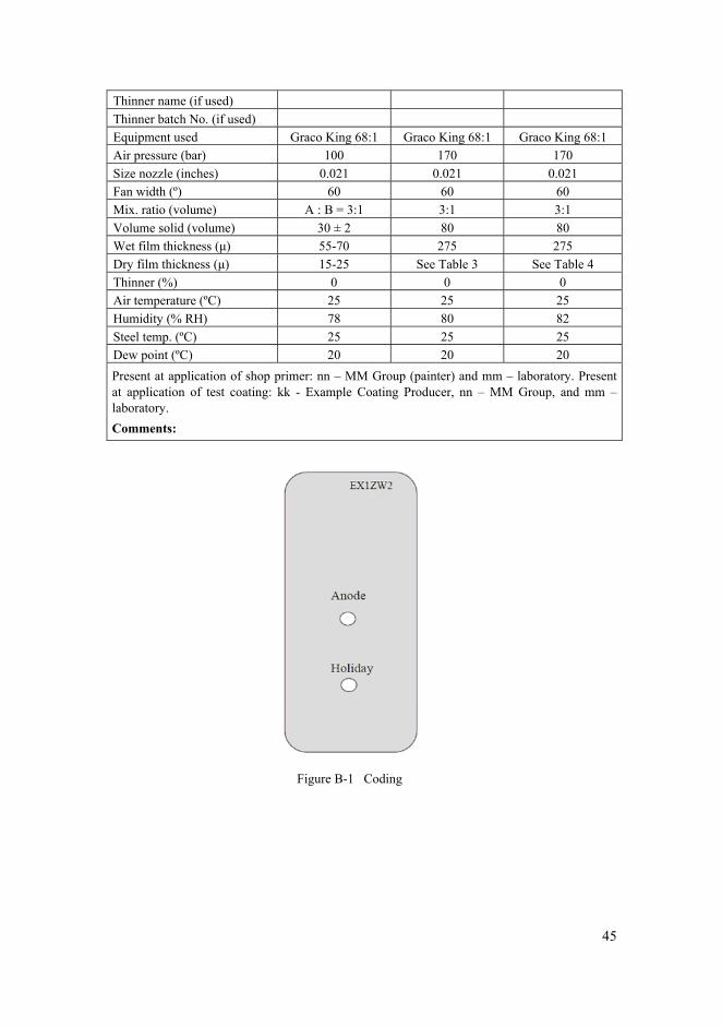
Thinner name (if used) Thinner batch No. (if used) Equipment used Graco King 68:1 Graco King 68:1 Graco King 68:1 Air pressure (bar) 100 170 170 Size nozzle (inches) 0.021 0.021 0.021 Fan width (º) 60 60 60 Mix. ratio (volume) A : B = 3:1 3:1 3:1 Volume solid (volume) 30 ± 2 80 80 Wet film thickness (μ) 55-70 275 275 Dry film thickness (μ) 15-25 See Table 3 See Table 4 Thinner (%) 0 0 0 Air temperature (ºC) 25 25 25 Humidity (% RH) 78 80 82 Steel temp. (ºC) 25 25 25 Dew point (ºC) 20 20 20 Present at application of shop primer: nn – MM Group (painter) and mm – laboratory. Present at application of test coating: kk - Example Coating Producer, nn – MM Group, and mm – laboratory. Comments:
Figure B-1 Coding
45
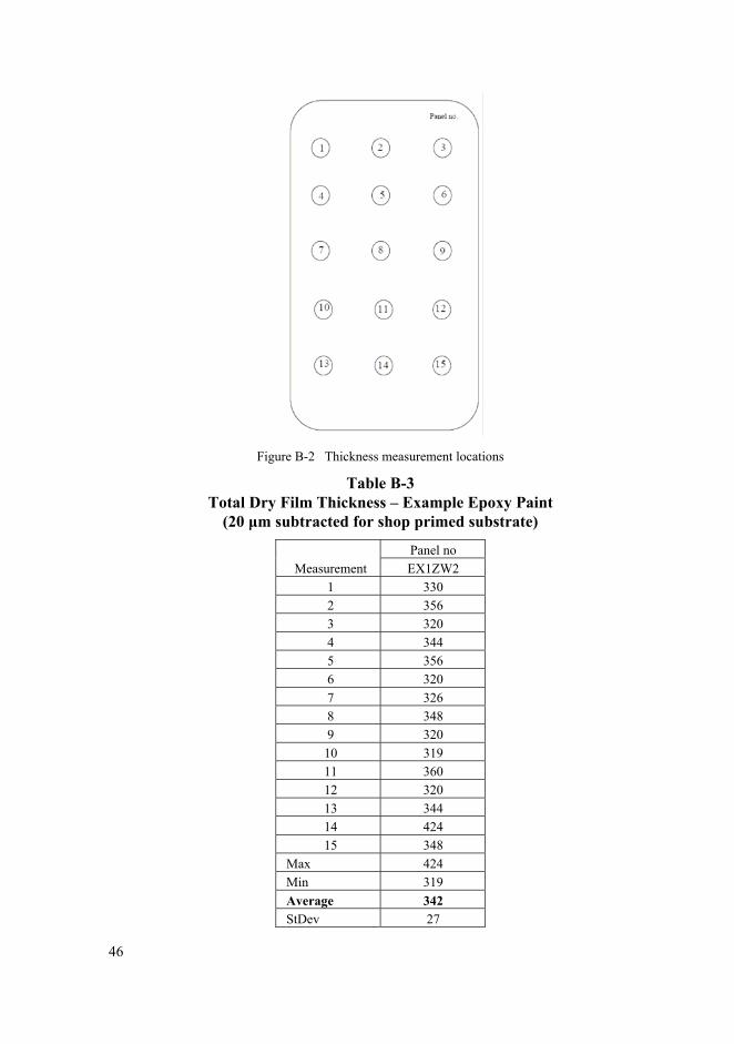
Figure B-2 Thickness measurement locations
Table B-3 Total Dry Film Thickness – Example Epoxy Paint
(20 μm subtracted for shop primed substrate)
Panel no Measurement EX1ZW2
1 330 2 356 3 320 4 344 5 356 6 320 7 326 8 348 9 320 10 319 11 360 12 320 13 344 14 424 15 348
Max 424 Min 319 Average 342 StDev 27
46
Table B-4 Development of blisters and rust after exposure
Code Description Blister size
Blister density Rust Other
defects EX1ZW2 Bottom wave tank panel
with anode 0 0 0 0
Table B-5 Results of the Pull-off adhesion test, wave tank and heat exposed panels
Panel no. Adhesion strength (MPa) Fracture
5.3 30 % B, 20 % C, 20 % C/D, 30 % D 4.2 30 % B, 20 % C, 30 % C/D, 20 % D
Bottom wave tank panel with anode W2 6.1 20 % B, 30 % C, 30 % C/D, 20 % D Average 5.2 70 – 80 % Cohesive failure, 20 – 30 % Adhesive Max 6.1 Min 4.2
A/B Fracture between the steel surface and 1st coat (shop primer). B Fracture in the 1st coat. B/C Fracture between the 1st and 2nd coat. C Fracture in the 2nd coat. C/D Fracture between the 2nd and 3rd coat. D Fracture in the 3rd coat -/Y Fracture between the outer coat and the glue.
Table B-8 Results of Cathodic Protection (CP)
Panel Cathodic
disbondment (mm)
Blisters / rust Zinc anode weight loss
(g)
Current demand
(mA/ m2) EX1ZW2 7.2 0 1.2345 3.32
Exposure time: 120 days (Total time 180 days. Each cycle consists of 2 weeks’ seawater immersion and 1 week exposure in air)
Utilisation factor: 0.8 Consumption rate for Zn-anodes: 11.3 kg/year
Cathodic protection; disbonding from artificial holiday: “On completion of the test, thoroughly rinse the panel with tap water, taking care not to damage
the coating.” (From ISO 15711:2003) “Assess loss of adhesion at the artificial holiday by using a sharp knife to make two cuts
through the coating to the substrates, intersection at the holiday. With the point of the knife, attempt to lift and peel back the coating from around the holiday. Record whether the adhesion of the coating to the substrate has been reduced and the approximate distance, in millimetres, that the coating can be peeled.” (Acc. to ISO 15711:2003)
47
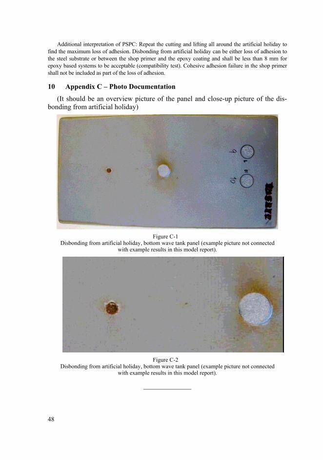
Additional interpretation of PSPC: Repeat the cutting and lifting all around the artificial holiday to find the maximum loss of adhesion. Disbonding from artificial holiday can be either loss of adhesion to the steel substrate or between the shop primer and the epoxy coating and shall be less than 8 mm for epoxy based systems to be acceptable (compatibility test). Cohesive adhesion failure in the shop primer shall not be included as part of the loss of adhesion.
10 Appendix C – Photo Documentation
(It should be an overview picture of the panel and close-up picture of the dis-bonding from artificial holiday)
Figure C-1
Disbonding from artificial holiday, bottom wave tank panel (example picture not connected with example results in this model report).
Figure C-2
Disbonding from artificial holiday, bottom wave tank panel (example picture not connected with example results in this model report).
48