Embed Size (px)
Citation preview

P r o x i m i t y L a s e r S c a n n e rP L S 1 0 X - 3 17
TE
CH
NI
CA
LD
ES
CR
IP
TI
ON

Certification Technical Description
2 © SICK AG · Industrial Safety Systems · Germany · All rights reserved 8 009 809/OA87/12-10-04
38 009 809/OA87/12-10-04 © SICK AG • Industrial Safety Systems • Germany • All rights reserved
Table of Contents
0 General Safety Notes and Protective Measures ....................... 4
1 Approval and Certificates .................................................................... 5
2 Notices / Regulation Use ..................................................................... 6
3 How the PLS Works ................................................................................ 7
Principle of function .................................................................... 7
Fields and measuring range of the PLS ............................. 8
4 Fields of Application - What the PLS Can Do .............................. 9
Area protection ............................................................................. 9
Internal space protection ......................................................... 9
Vehicle protection and navigation ....................................... 10
Measurement of contours ..................................................... 10
5 Location planning ..................................................................................11
Range of the PLS ....................................................................... 11
5.1 Stationary protection with PLS ............................................12
Important notes on configuration ....................................... 12
Location planning ...................................................................... 13
Restart definition ........................................................................ 16
Mounting recommendations for PLS ................................. 16
5.2 Mobile protection with PLS ...................................................19
Location planning ..................................................................... 20
Calculation of the necessary protective fields .............21
Configuration examples ........................................................ 22
5.3 If you use several PLS units ................................................ 23
6 Supply Package ..................................................................................... 24
Recommended accessories ................................................ 24
Connection set .......................................................................... 24
Interface cable ........................................................................... 24
7 Mounting the PLS ................................................................................. 25
8 Connecting the PLS ............................................................................. 28
Connecting the power connector X1. ............................... 29
Connection examples ............................................................. 29
Notes about the connection examples ........................... 33
Connecting the interface connector X2. ......................... 34
Short-term connection to a PC ........................................... 35
Permanent connection to an evaluation computer .... 35
9 Programming the PLS with the User Software ........................ 36
9.1 Installing the user software ................................................. 36
System requirements ............................................................. 36
9.2 What to do ................................................................................... 37
Essential steps ........................................................................... 37
Other options .............................................................................. 37
9.3 Starting: the initial configuration ........................................ 38
Configure hardware ................................................................. 39
Send configuration to PLS .................................................... 42
Edit monitoring range .............................................................. 43
Send monitoring range to PLS ............................................ 46
9.4 Edit / dimension fields ............................................................47
Convert fields .............................................................................. 47
Change scale of segmented field ....................................... 47
Copy and paste fields ............................................................. 48
Save individual fields ............................................................... 48
Fix co-ordinates ......................................................................... 48
9.5 Teach-in protective field ....................................................... 49
9.6 Monitor protective field ..........................................................51
9.7 Check settings .......................................................................... 52
9.8 Receive and store configuration ....................................... 53
9.9 Change password .................................................................... 54
9.10 Change screen view ............................................................... 55
9.11 Interrogate fault memory
(system diagnosis) ...................................................................57
Initial fault diagnosis ................................................................57
Interrogate PLS fault memory ..............................................57
10 Checks ...................................................................................................... 59
10.1 Check PLS ................................................................................... 59
10.2 Check list ..................................................................................... 60
11 Care and Maintenance .......................................................................61
11.1 SICK Service / Hotline ............................................................61
11.2 LEDs on the PLS ...................................................................... 62
11.3 PLS fault table ........................................................................... 63
11.4 Service questionnaire ............................................................ 65
12 Appendix ...................................................................................................67
12.1 Characteristics ...........................................................................67
12.2 Accessories ................................................................................ 68
Mounting kits .............................................................................. 68
Connection set .......................................................................... 68
Interface cables ........................................................................ 68
Documentation and PLS / LSI user software ................ 68
Other SICK accessories ........................................................ 68
And also ....................................................................................... 68
12.3 Technical data ........................................................................... 69
12.4 Standards and regulations ................................................... 73
13 Glossary .................................................................................................... 74
This technical description contains all the information necessary
for project planning and setting up the PLS. You will find in it the
information you need for mechanical mounting, electrical
installation and programming of the PLS.
The description covers the following PLS type:
– PLS 10X-317 (certified for personal protection
to IEC/EN 61496-1)
Along with the technical description, you are also provided with
an instruction manual containing important information for day-
to-day use of the PLS.
Keep the technical description and instruction manual readily to
hand at all times.
The information given in this description can be altered and
amended without prior notice.
Essential chapters you should read:
General safety notes ..................................... Chapter 0
Important notes ............................................... Chapter 2
Location planning ............................................ Chapter 5
Supply / package
Mounting and connecting up the PLS .... Chapters 6 to 8
Getting to know the user software .......... Sections 9.1 to 9.3
Checks ................................................................. Chapter 10
Technical data .................................................. Section 12.3

4 © SICK AG • Industrial Safety Systems • Germany • All rights reserved 8 009 809/OA87/12-10-04
0 General Safety Notes and Protective Measures
Safety regulations and notes
1. The use/installation of proximity scanners used as non-
contact protective devices, as well as the recurrent technical
checks, are covered by national/international legal regula-
tions, in particular
� Machine Directive 98/37 EU,
� Use of Work Materials Directive 89/655 EEC,
� the safety regulations and
� the accident prevention and safety regulations.
Manufacturers and operators of machinery equipped with
our protective systems are responsible for consulting with
the relevant authorities about, and complying with, all the
applicable safety regulations.
2. Furthermore, our instructions, particularly with regards tothe check regulations (see Chapter 10 “Checks”) detailed
in this technical description or instruction manual (e.g.
concerning the use, extension, installation or integration in
the machine controller), must be heeded and complied with
without fail.
3. The checks must be carried out by skilled or authorisedand instructed personnel, and are to be documented in a
clear and comprehensible manner.
4. Our operating instructions are to be made available to the
employee (operator) using the machinery equipped with our
protective systems. The employee is to be instructed in their
use by skilled personnel.
5. A check list for manufacturer and outfitter checks is supplied
as an enclosure to this brochure.

58 009 809/OA87/12-10-04 © SICK AG • Industrial Safety Systems • Germany • All rights reserved
1 Declaration of Conformity
6 © SICK AG • Industrial Safety Systems • Germany • All rights reserved 8 009 809/OA87/12-10-04
2 Notices / Regulation Use
The PLS proximity laser scanner is a device designed to protect
people and property. It is intended to monitor hazardous areas in
enclosed spaces. PLS is not designed for outdoor use.
Observe the instructions relating to regulation use. SICK cannot
be held liable for damage arising from use of the PLS other than
stipulated.
� Install the PLS in a dry location and protect the unit against
dirt and damage.
� Lay all wires and connecting cables such that they are
protected against damage.
� Avoid the creation of strong electrical fields which could, for
example, arise in the immediate vicinity of welding or
induction cables, or which could also be caused by mobile
telephones being used nearby.
� Make sure that no obstacles in the monitoring range can
obstruct the field of vision of the PLS or cause shadows.
Such shadow areas cannot be monitored by the PLS. Where
there are unavoidable areas of shadow, check whether they
present any risk. Take additional precautionary measures as
necessary.
� Keep the monitoring range free of smoke, fog, steam and
other air pollution. The functioning of the PLS may otherwise
be impaired and error shutdowns may occur.
� Avoid placing strongly reflective objects such as retroreflec-
tors in the scanning plane of the PLS, as they may influence
its measurement results.
� Mount the PLS so that it cannot be dazzled by sunlight. Also
avoid stroboscopic and fluorescent lamps, as they may influ-
ence the PLS under certain circumstances.
� In mounting, installation and use of the PLS, observe the
standards and regulations applicable in your country. The
Appendix presents a summary of the most important regu-
lations.
� For programming of the monitoring range, take note of the
description of the user software as from Chapter 9. This
describes how to connect the PLS to a PC and how to work
with the user software.
� Before releasing the machine for use, test whether access to
the hazard area is fully covered by the safety devices. After
release, also check at regular intervals (such as every
morning before beginning work) that the PLS is activated
properly when an infringement of the protective field occurs.
This test should be carried out along all protective field limits,
in accordance with application-specific regulations.
� If you employ the PLS for vehicle protection: please note that
the PLS can only be used on electrically driven vehicles.
� The PLS must be disposed of in a proper and environmen-
tally friendly manner at the end of its useful service life.
78 009 809/OA87/12-10-04 © SICK AG • Industrial Safety Systems • Germany • All rights reserved
3 How the PLS Works
Principle of function
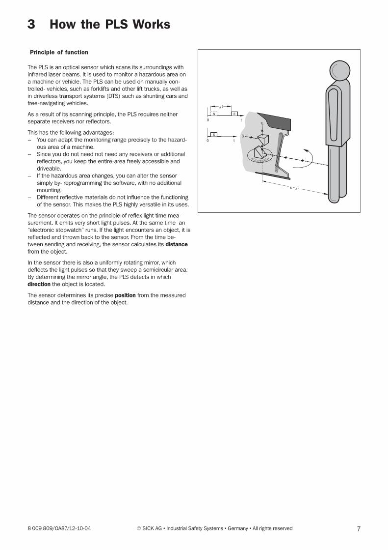
The PLS is an optical sensor which scans its surroundings with
infrared laser beams. It is used to monitor a hazardous area on
a machine or vehicle. The PLS can be used on manually con-
trolled- vehicles, such as forklifts and other lift trucks, as well as
in driverless transport systems (DTS) such as shunting cars and
free-navigating vehicles.
As a result of its scanning principle, the PLS requires neither
separate receivers nor reflectors.
This has the following advantages:
– You can adapt the monitoring range precisely to the hazard-
ous area of a machine.
– Since you do not need not need any receivers or additional
reflectors, you keep the entire-area freely accessible and
driveable.
– If the hazardous area changes, you can alter the sensor
simply by- reprogramming the software, with no additional
mounting.
– Different reflective materials do not influence the functioning
of the sensor. This makes the PLS highly versatile in its uses.
The sensor operates on the principle of reflex light time mea-
surement. It emits very short light pulses. At the same time an
“electronic stopwatch” runs. If the light encounters an object, it is
reflected and thrown back to the sensor. From the time be-
tween sending and receiving, the sensor calculates its distancefrom the object.
In the sensor there is also a uniformly rotating mirror, which
deflects the light pulses so that they sweep a semicircular area.
By determining the mirror angle, the PLS detects in which
direction the object is located.
The sensor determines its precise position from the measured
distance and the direction of the object.
E
S0 t
S
S E
0 t
s ~ t
t∆
∆
8 © SICK AG • Industrial Safety Systems • Germany • All rights reserved 8 009 809/OA87/12-10-04
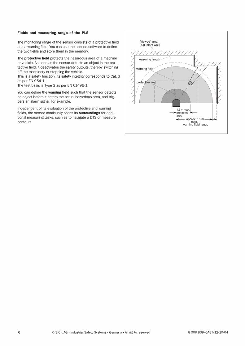
Fields and measuring range of the PLS
The monitoring range of the sensor consists of a protective field
and a warning field. You can use the applied software to define
the two fields and store them in the memory.
The protective field protects the hazardous area of a machine
or vehicle. As soon as the sensor detects an object in the pro-
tective field, it deactivates the safety outputs, thereby switching
off the machinery or stopping the vehicle.
This is a safety function. Its safety integrity corresponds to Cat. 3
as per EN 954-1:
The test basis is Type 3 as per EN 61496-1
You can define the warning field such that the sensor detects
on object before it enters the actual hazardous area, and trig-
gers an alarm signal, for example.
Independent of its evaluation of the protective and warning
fields, the sensor continually scans its surroundings for addi-
tional measuring tasks, such as to navigate a DTS or measure
contours.
'Viewed' area(e.g. plant wall)
measuring length
warning field
protective field
1.5 m max.protectedarea
approx 15 mmax.
warning field range
98 009 809/OA87/12-10-04 © SICK AG • Industrial Safety Systems • Germany • All rights reserved
4 Fields of Application � What the PLS Can Do
These pages provide an overview of the key fields of applica-tion
of the PLS.
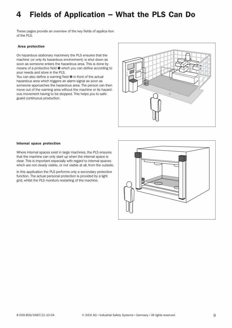
Area protection
On hazardous stationary machinery the PLS ensures that the
machine (or only its hazardous environment) is shut down as
soon as someone enters the hazardous area. This is done by
means of a protective field ➊ which you can define according to
your needs and store in the PLS.
You can also define a warning field ➋ in front of the actual
hazardous area which triggers an alarm signal as soon as
someone approaches the hazardous area. The person can then
move out of the warning area without the machine or its hazard-
ous movement having to be stopped. This helps you to safe-
guard continuous production.
Internal space protection
Where internal spaces exist in large machines, the PLS ensures
that the machine can only start up when the internal space is
clear. This is important especially with regard to internal spaces
which are not clearly visible, or not visible at all, from the outside.
In this application the PLS performs only a secondary protective
function. The actual personal protection is provided by a light
grid, whilst the PLS monitors restarting of the machine.
10 © SICK AG • Industrial Safety Systems • Germany • All rights reserved 8 009 809/OA87/12-10-04
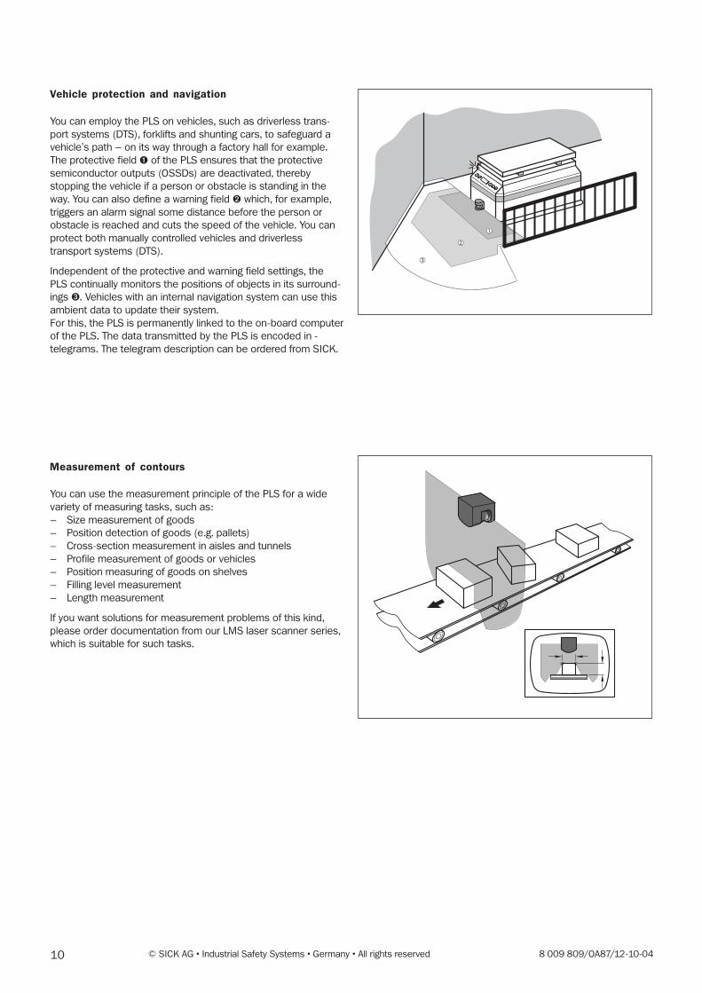
Vehicle protection and navigation
You can employ the PLS on vehicles, such as driverless trans-
port systems (DTS), forklifts and shunting cars, to safeguard a
vehicle's path – on its way through a factory hall for example.
The protective field ➊ of the PLS ensures that the protective
semiconductor outputs (OSSDs) are deactivated, thereby
stopping the vehicle if a person or obstacle is standing in the
way. You can also define a warning field ➋ which, for example,
triggers an alarm signal some distance before the person or
obstacle is reached and cuts the speed of the vehicle. You can
protect both manually controlled vehicles and driverless
transport systems (DTS).
Independent of the protective and warning field settings, the
PLS continually monitors the positions of objects in its surround-
ings ➌. Vehicles with an internal navigation system can use this
ambient data to update their system.
For this, the PLS is permanently linked to the on-board computer
of the PLS. The data transmitted by the PLS is encoded in -
telegrams. The telegram description can be ordered from SICK.
Measurement of contours
You can use the measurement principle of the PLS for a wide
variety of measuring tasks, such as:
– Size measurement of goods
– Position detection of goods (e.g. pallets)
– Cross-section measurement in aisles and tunnels
– Profile measurement of goods or vehicles
– Position measuring of goods on shelves
– Filling level measurement
– Length measurement
If you want solutions for measurement problems of this kind,
please order documentation from our LMS laser scanner series,
which is suitable for such tasks.
➂
➀
➁
118 009 809/OA87/12-10-04 © SICK AG • Industrial Safety Systems • Germany • All rights reserved
5 Location Planning
The PLS monitors hazardous areas and protects operating per-
sonnel and plants. To enable it to fulfil these tasks, you need to
observe a number of rules and safety criteria when choosing its
location. The key information with regard to this is presented on
the following pages.
Note:It may be that other standards and regulations not cited hereare also of importance to your application.If you are uncertain about your application, please contact your
local SICK office.
Always choose a location
– which provides the maximum safety in the hazardous area,
– in which no obstacles can obstruct the field of vision of the
PLS or cause umber shadows,
– in which the PLS is protected against damp, dirt and dam-
age,
– in which the PLS is not influenced by sunlight or artificial light
sources,
– which is as accessible as possible for electrical installation
work.
Please note that intrusion into needle-formed protective fields/
protective field sections (protective field segments only consist
of a single pixel) is ignored by the device for reasons of availabil-
ity.
If such forms of protective fields cannot be avoided, always
programme at least one more adjacent pixel.
Approval of the PLS for use as a personal protection appliance is
based on area protection. Other mounting locations are,
following an assessment of potential risks and with the approval
of the relevant authorities, also possible. The possibility of
people being endangered must always be excluded.
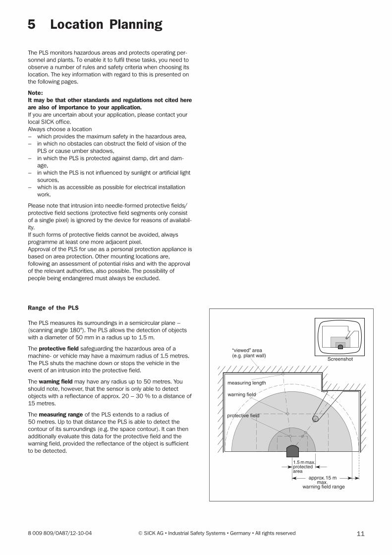
Range of the PLS
The PLS measures its surroundings in a semicircular plane –
(scanning angle 180°). The PLS allows the detection of objects
with a diameter of 50 mm in a radius up to 1.5 m.
The protective field safeguarding the hazardous area of a
machine- or vehicle may have a maximum radius of 1.5 metres.
The PLS shuts the machine down or stops the vehicle in the
event of an intrusion into the protective field.
The warning field may have any radius up to 50 metres. You
should note, however, that the sensor is only able to detect
objects with a reflectance of approx. 20 – 30 % to a distance of
15 metres.
The measuring range of the PLS extends to a radius of
50 metres. Up to that distance the PLS is able to detect the
contour of its surroundings (e.g. the space contour). It can then
additionally evaluate this data for the protective field and the
warning field, provided the reflectance of the object is sufficient
to be detected.
1.5 m max.protectedarea
12 © SICK AG • Industrial Safety Systems • Germany • All rights reserved 8 009 809/OA87/12-10-04
5.1 Stationary protection with PLS
Important notes on configuration
The sensor should preferably be operated in an extern
realised “with restart inhibit” mode for area protection. The
regulations applicable to the machine must be observed.
In this case the actuating element for the restart inhibit of
the machine must be mounted in a way, that the hazardous
area is completely visible from that place.
During operation of the machine without restart inhibit the
close-up zone1) of the sensor (4 cm wide area measured
from the front screen outer area) is either to be rendered
inaccessible (e.g. by a bar or undercut), or a proximity
scanner with a 4 cm detection range is to be mounted over
the sensor.
For area protection, side access to the machine base is also
to be taken into account when configuring the protective
field. This assumes that a person approaches the machine
base from the side. If side access is possible (no solid
restrictions such as a wall), the protective field should be
configured wider than the machine base.
The maximum measuring error is 94 mm.
For both graphic and numerical programming, it must be
ensured for reasons of functionality (solid barriers should not
lead to unintentional shutdown) that where fixed contours
exist a distance of 94 mm is observed.
Where the teach-in function is used, a 45 mm supplement
on top of the maximum measuring error is required for the
accuracy of the learned contour.
Recommendation:When installing stationary plants, it is recommended thatyou mark out the shape of the protective field on thefloor to make it easier to perform the regular machinerychecks.
1) An optical radar cannot distinguish between a dirty
front screen and an obstacle directly in front of the
sensor. For the sake of functionality, the PLS was
designed to reliably detect solid black bodies such as
black cord or shoe leather only at a distance of 4 cm
measured from the outer contour of the front screen.
138 009 809/OA87/12-10-04 © SICK AG • Industrial Safety Systems • Germany • All rights reserved
Case 2b: Scanning plane at maximum height, not parallel to
ground (HD = 875)
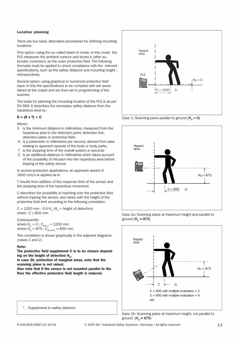
Location planning
There are two basic alternative procedures for defining mounting
locations:
First option: using the so-called teach-in mode. In this mode the
PLS measures the ambient contour and stores it (after au-
tomatic correction) as the outer protective field. The following
formulae must be applied to check compliance with the relevant
specifications, such as the safety distance and mounting height-,
retrospectively.
Second option: using graphical or numerical protective field
input. In this the specifications to be complied with are ascer-
tained at the outset and are then set in programming of the
scanner.
The basis for planning the mounting location of the PLS is as per
EN 999. It describes the necessary safety distance from the
hazardous area by:
S = (K x T) + C
Where:
S is the minimum distance in millimetres, measured from the
hazardous area to the detection point, detection line,
detection plane or protective field;
K is a parameter in millimetres per second, derived from data
relating to approach speeds of the body or body parts;
T is the stopping time of the overall system in seconds
C is an additional distance in millimetres which takes account
of the possibility of intrusion into the hazardous area before
tripping of the safety device.
In access protection applications, an approach speed of
1600 mm/s is applied as K.
T results from addition of the response time of the sensor and
the stopping time of the hazardous movement.
C describes the possibility of reaching over the protective field
without tripping the sensor, and varies with the height of the
protective field limit according to the following correlation:
C = 1200 mm - 0.4 HD (H
D = height of detection)
where C ≥ 850 mm
Consequently:
where HD = 0 : C
HD=0 = 1200 mm
where HD = 875 : C
HD=875 = 850 mm
This correlation is shown graphically in the adjacent diagrams
(cases 1 and 2).
Note:The protective field supplement C is to be chosen depend-ing on the height of detection H
D.
In case 2b, protection of marginal areas, note that thescanning plane is not raised.Also note that if the sensor is not mounted parallel to thefloor the effective protective field length is reduced.
Case 1: Scanning plane parallel to ground (HD = 0)
Hazardarea
PLS
C = 1200
HD = 0
1)
Hazardarea
C = 850
HD = 875
1)
Hazardarea
C = 900 with multiple evaluation = 2
C = 950 with multiple evaluation = 4
etc.
HD = 875
C 1)
Case 2a: Scanning plane at maximum height and parallel to
ground (HD = 875)
1) Supplement to safety distance
14 © SICK AG • Industrial Safety Systems • Germany • All rights reserved 8 009 809/OA87/12-10-04
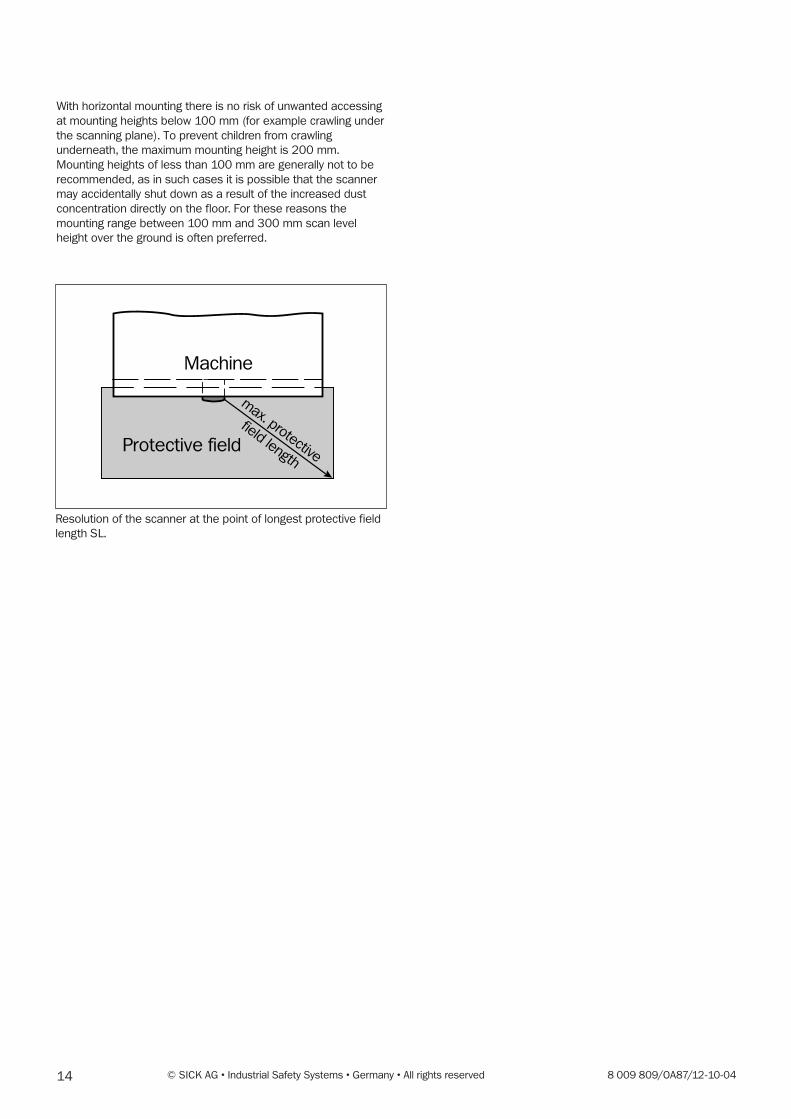
Machine
Protective field
max. protective
field length
With horizontal mounting there is no risk of unwanted accessing
at mounting heights below 100 mm (for example crawling under
the scanning plane). To prevent children from crawling
underneath, the maximum mounting height is 200 mm.
Mounting heights of less than 100 mm are generally not to be
recommended, as in such cases it is possible that the scanner
may accidentally shut down as a result of the increased dust
concentration directly on the floor. For these reasons the
mounting range between 100 mm and 300 mm scan level
height over the ground is often preferred.
Resolution of the scanner at the point of longest protective field
length SL.
158 009 809/OA87/12-10-04 © SICK AG • Industrial Safety Systems • Germany • All rights reserved
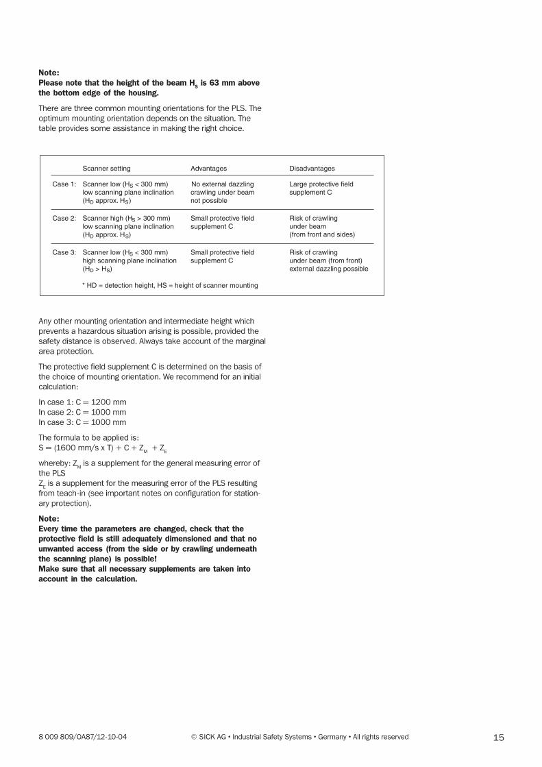
Note:Please note that the height of the beam H
S is 63 mm above
the bottom edge of the housing.
There are three common mounting orientations for the PLS. The
optimum mounting orientation depends on the situation. The
table provides some assistance in making the right choice.
Advantages Disadvantages
Scanner low (HSlow scanning plane inclination(HD approx. HS)
Scanner high (HS > 300 mm)low scanning plane inclination(HD approx. HS)
Scanner low (HS < 300 mm)high scanning plane inclination(HD > HS)
Scanner setting
< 300 mm)crawling under beam not possible
Small protective fieldsupplement C
Small protective fieldsupplement C
Large protective fieldNo external dazzlingsupplement C
Risk of crawling under beam(from front and sides)
Risk of crawlingunder beam (from front)external dazzling possible
Case 1:
Case 2:
Case 3:
* HD = detection height, HS = height of scanner mounting
Any other mounting orientation and intermediate height which
prevents a hazardous situation arising is possible, provided the
safety distance is observed. Always take account of the marginal
area protection.
The protective field supplement C is determined on the basis of
the choice of mounting orientation. We recommend for an initial
calculation:
In case 1: C = 1200 mm
In case 2: C = 1000 mm
In case 3: C = 1000 mm
The formula to be applied is:
S = (1600 mm/s x T) + C + ZM + Z
E
whereby: ZM is a supplement for the general measuring error of
the PLS
ZE is a supplement for the measuring error of the PLS resulting
from teach-in (see important notes on configuration for station-
ary protection).
Note:Every time the parameters are changed, check that theprotective field is still adequately dimensioned and that nounwanted access (from the side or by crawling underneaththe scanning plane) is possible!Make sure that all necessary supplements are taken intoaccount in the calculation.
16 © SICK AG • Industrial Safety Systems • Germany • All rights reserved 8 009 809/OA87/12-10-04
Restart definition
The machine should preferably be operated with restart inhibit.
A restart inhibit is always essential when the protective field can
be exited towards the hazardous area. Where necessary, check
whether this can be prevented by plant design (see following
subsection: Mounting recommendations for PLS).
If a machine can only be operated without restart inhibit, it is
essential that the following points should be observed.
– A person must be reliably detected at every point in the
hazardous area.
– A person must not be allowed to exit the protective field in
the direction of the hazardous area (such as by crawling un-
derneath it, stepping behind it or climbing over it).
Make sure this is prevented by plant design (see following sub-
section: Mounting recommendations for PLS)!
Mounting recommendations for PLS
The following considerations must be taken into account when
designing the plant:
The mirror pivot point of the PLS determines the position of the
front edge of the protective field. Since the mounting area and
the mirror pivot point are at a set distance from one another, a
zone is produced in front of the mounting area which is not de-
tected by the scanner.
This zone becomes Iarger if the PLS is mounted on the mounting
bracket, for example. The size of this dead zone – measured
from the back edge of the PLS or the mounting kit – is:
PLS direct-mounted 109 mm
PLS with mounting kit 1 112 mm
PLS with mounting kit 1 and 2 127 mm
PLS with mounting kit 1, 2 and 3 142 mm
There are cases in which design measures must be applied to
prevent persons from being in the hazardous area but outside
the protective field (such as by crawling un-derneath it, stepping
behind it or climbing over it).
To exclude this possibility where a laser scanner is mounted on
the machine, one of the following measures (or a combination of
them) is essential:
– undercutting,
– retraction of the laser scanner,
– mounting of the laser scanner opposite or to the side of the
machine base.
178 009 809/OA87/12-10-04 © SICK AG • Industrial Safety Systems • Germany • All rights reserved
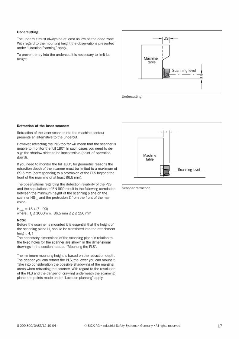
Undercutting:
The undercut must always be at least as low as the dead zone.
With regard to the mounting height the observations presented
under “Location Planning” apply.
To prevent entry into the undercut, it is necessary to limit its
height.
Retraction of the laser scanner:
Retraction of the laser scanner into the machine contour
presents an alternative to the undercut.
However, retracting the PLS too far will mean that the scanner is
unable to monitor the full 180°. In such cases you need to de-
sign the shadow sides to he inaccessible (point-of-operation
guard).
If you need to monitor the full 180°, for geometric reasons the
retraction depth of the scanner must be limited to a maximum of
69.5 mm (corresponding to a protrusion of the PLS beyond the
front of the machine of at least 86.5 mm).
The observations regarding the detection reliability of the PLS
and the stipulations of EN 999 result in the following correlation
between the minimum height of the scanning plane on the
scanner HSmin
and the protrusion Z from the front of the ma-
chine.
HSmin
= 15 x (Z - 90)
where: HS ≤ 1000mm, 86.5 mm ≤ Z ≤ 156 mm
Note:Before the scanner is mounted it is essential that the height of
the scanning plane HS should be translated into the attachment
height HA !
The necessary dimensions of the scanning plane in relation to
the fixed holes for the scanner are shown in the dimensional
drawings in the section headed “Mounting the PLS”.
The minimum mounting height is based on the retraction depth.
The deeper you can retract the PLS, the lower you can mount it.
Take into consideration the possible shadowing of the marginal
areas when retracting the scanner. With regard to the resolution
of the PLS and the danger of crawling underneath the scanning
plane, the points made under “Location planning” apply.
Undercutting
Machinetable
Scanning level
US
H
Scanner retraction
Scanning level
Machinetable
Z
18 © SICK AG • Industrial Safety Systems • Germany • All rights reserved 8 009 809/OA87/12-10-04
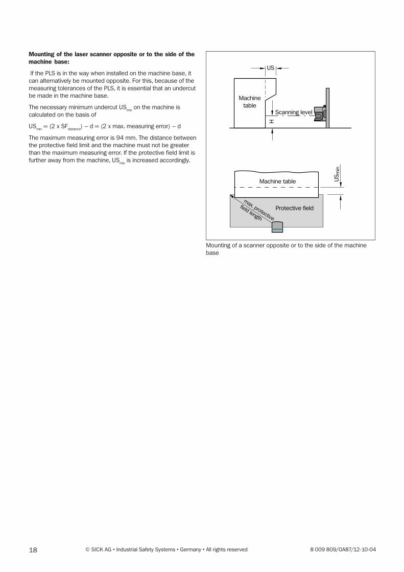
Mounting of the laser scanner opposite or to the side of themachine base:
lf the PLS is in the way when installed on the machine base, it
can alternatively be mounted opposite. For this, because of the
measuring tolerances of the PLS, it is essential that an undercut
be made in the machine base.
The necessary minimum undercut USmin
on the machine is
calculated on the basis of
USmin
= (2 x SFdistance
) – d = (2 x max. measuring error) – d
The maximum measuring error is 94 mm. The distance between
the protective field limit and the machine must not be greater
than the maximum measuring error. If the protective field limit is
further away from the machine, USmin
is increased accordingly.
Mounting of a scanner opposite or to the side of the machine
base
Machine
tableScanning level
US
Machine table
Protective field
US
min
H
max. protective
field length
198 009 809/OA87/12-10-04 © SICK AG • Industrial Safety Systems • Germany • All rights reserved
5.2 Mobile protection with PLS
In mobile applications the sensor should – depending of the
individual case – be operated in an extern realised “with restart
inhibit“ mode.
The regulations applicable to the machine must be observed.
In this case the actuating element for the restart inhibit must be
mounted in a way, that the hazardous area is completely visible
from that place. The actuating element for the restart inhibit
must not be accessible from the point directly in front of the
sensor.
During operation of the machine without restart inhibit the close-
up zone1) of the sensor (4 cm wide area measured from the
front screen outer area) is either to be rendered inaccessible
(e.g. by a bar or undercut) or a proximity scanner with a 4 cm
detection range is to be mounted over the sensor.
For mobile protection, side access to the vehicle is also to be
taken into account when configuring the protective field. This
assumes that a person approaches the vehicle from the side, for
instance in concealed areas (e.g. crossways). If side access is
possible (no solid restrictions such as a wall), the protective field
should be configured wider than the vehicle.
The maximum measuring area is 94 mm.
For both graphic and numerical programming, it must be
ensured for reasons of functionality (solid barriers should not
lead to unintentional shutdown) that where fixed contours exist a
distance of 94 mm is observed.
Where the teach-in function is used, a 45 mm supplement on
top of the maximum measuring error is required for the accuracy
of the learned contour.
Recommendation:When installing mobile plants, you are advised to attach anotice or a configuration diagram to the vehicle to simplifythe regular checks.
1) An optical radar cannot distinguish between a dirty
front screen and an obstacle directly in front of the
sensor. For the sake of functionality, the PLS was
designed to reliably detect solid black objects such
as black cord or black shoe leather only at a
distance of 4 cm measured from the outer contour
of the front screen.
20 © SICK AG • Industrial Safety Systems • Germany • All rights reserved 8 009 809/OA87/12-10-04
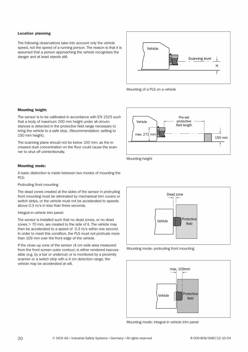
Location planning
The following observations take into account only the vehicle
speed, not the speed of a running person. The reason is that it is
assumed that a person approaching the vehicle recognises the
danger and at least stands still.
Mounting height:
The sensor is to be calibrated in accordance with EN 1525 such
that a body of maximum 200 mm height under all circum-
stances is detected in the protective field range necessary to
bring the vehicle to a safe stop. (Recommendation: setting to
150 mm height).
The scanning plane should not be below 100 mm, as the in-
creased dust concentration on the floor could cause the scan-
ner to shut off unintentionally.
Mounting mode:
A basic distinction is made between two modes of mounting the
PLS:
Protruding front mounting
The dead zones created at the sides of the sensor in protruding
front mounting must be eliminated by mechanical trim covers or
switch strips, or the vehicle must not be accelerated to speeds
above 0.3 m/s in less than three seconds.
Integral in-vehicle trim panel:
The sensor is installed such that no dead zones, or no dead
zones > 70 mm, are created to the side of it. The vehicle may
then be accelerated to a speed of 0.3 m/s within one second.
In order to meet this condition, the PLS must not protrude more
than 109 mm over the front edge of the vehicle.
If the close-up zone of the sensor (4 cm wide area measured
from the front screen outer contour) is either rendered inacces-
sible (e.g. by a bar or undercut) or is monitored by a proximity
scanner or a switch strip with a 4 cm detection range, the
vehicle may be accelerated at will.
H
Vehicle
Scanning level
Mounting of a PLS on a vehicle
Pre-setprotectivefield length
150 mm
Vehicle
max. 272 mm
Mounting height
Mounting mode: protruding front mounting
Mounting mode: integral in vehicle trim panel
Dead zone
Protective
fieldVehicle
max. 109mm
Protective
fieldVehicle

218 009 809/OA87/12-10-04 © SICK AG • Industrial Safety Systems • Germany • All rights reserved
Calculation of the necessary protective field
When configuring the protective field for vehicle applications, in
addition to the actual stopping distance of the vehicle the
following supplements must also be taken into account:
For the protective field length SL:
SL = SA + Z
M + Z
E + Z
F + Z
B
where: SA is the stopping distance of the vehicle
ZM is the supplement for the general measuring error of the ve-
hicle;
ZE is the supplement for the measuring error of the PLS result-
ing from teach-in (see Important notes on configuration for
mobile protection);
ZF is the supplement for a lack of ground clearance of the
vehicle;
ZB is the supplement for the decreasing brake force of the
vehicle.
The stopping distance SA is composed of the actual braking
distance of the vehicle from maximum speed and the maximum
load SBr
, as well as its distance covered during the response
time of the sensor SAns
.
SA = S
Br + S
Ans
where SA is given in the specification of the vehicle manufac-
turer,
and SAns
= TAns
x Vmax
.
The response time of the sensor TAns
set when the PLS is
shipped is 80 ms.
The supplement ZM results from the maximum measuring dis-
tance of the PLS. The maximum measuring error is 94 mm. The
maximum protective field length SLmax
results from the maximum
distance of the edge of the protective field from the centre of
the PLS (see Important notes on configuration for mobile
protection).
The supplement ZE is necessary when you define the protective
field using the teach-in method. This supplement takes account
of the accuracy in registering the ambient contour. This supple-
ment is independent of background conditions, and needs to be
set at a constant 45 mm.
The supplement ZF is necessary because people are generally
detected above foot level, and so the braking action is unable to
take account of the length of the foot in front of the point of
detection. A person could therefore suffer injuries to the foot as
a result of a lack of ground clearance.
22 © SICK AG • Industrial Safety Systems • Germany • All rights reserved 8 009 809/OA87/12-10-04
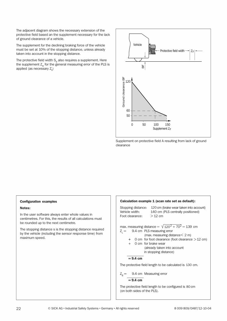
The adjacent diagram shows the necessary extension of the
protective field based an the supplement necessary for the lack
of ground clearance of a vehicle.
The supplement for the declining braking force of the vehicle
must be set at 10% of the stopping distance, unless already
taken into account in the stopping distance.
The protective field width SB also requires a supplement. Here
the supplement ZM for the general measuring error of the PLS is
applied (as necessary ZE)
Protective field width ZF
120
60
50
0 50 100 150
Vehicle
BF
Gro
und c
leara
nce B
F
Supplement ZF
Supplement on protective field A resulting from lack of ground
clearance
Configuration examples
Notes:
In the user software always enter whole values in
centimetres. For this, the results of all calculations must
be rounded up to the next centimetre.
The stopping distance s is the stopping distance required
by the vehicle (including the sensor response time) from
maximum speed.
238 009 809/OA87/12-10-04 © SICK AG • Industrial Safety Systems • Germany • All rights reserved
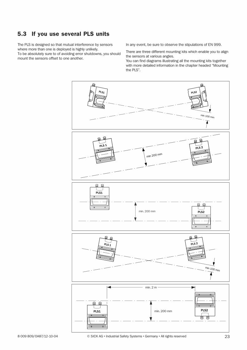
5.3 If you use several PLS units
In any event, be sure to observe the stipulations of EN 999.
There are three different mounting kits which enable you to align
the sensors at various angles.
You can find diagrams illustrating all the mounting kits together
with more detailed information in the chapter headed “Mounting
the PLS”.
The PLS is designed so that mutual interference by sensors
where more than one is deployed is highly unlikely.
To be absolutely sure to of avoiding error shutdowns, you should
mount the sensors offset to one another.
min 100 mm
PLS1 PLS2
min 200 mm
PLS 1PLS 2
min. 200 mm
PLS1
PLS2
min 100 mm
PLS 1 PLS 2
min. 2 m
min. 200 mmPLS1 PLS2

24 © SICK AG • Industrial Safety Systems • Germany • All rights reserved 8 009 809/OA87/12-10-04
6 Supply Package
You receive:
– one PLS sensor
– one connection set (one connection box each for power
supply and interface)
– the PLS user software (on two 3.5" floppy discs)
– the operating instructions manual
– this technical description manual
Recommended accessories
At this point we can only give you a few pointers to the major
accessories. You can find a complete list in the Appendix.
Connection set
You will normally receive connection set 1. It contains one
connection box each for the power supply and the interface,
without cables.
If you wish, instead of connection set 1 you can order one of the
connection sets 2 to 7, which include a cable fitted to the power
connector. The cable is routed upward out of the connection
box.
Various cable lengths are available:
Order no.
Connection set 1, without cable 2 016 184
Connection set 2, with 3 m cable 2 016 185
Connection set 3, with 5 m cable 2 016 186
Connection set 4, with 10 m cable 2 016 187
Connection set 5, with 15 m cable 2 016 188
Connection set 6, with 20 m cable 2 016 189
Connection set 7, with 30 m cable 2 016 190
Interface cable
To connect the sensor to a PC you can use the interface cable.
It is available in three lengths.
For RS 232:
Order no.
3 m interface cable 2 016 401
5 m interface cable 2 016 402
10 m interface cable 2 016 403
For RS 422:
Order no.
3 m interface cable 2 019 130
5 m interface cable 2 019 131
10 m interface cable 2 019 132
258 009 809/OA87/12-10-04 © SICK AG • Industrial Safety Systems • Germany • All rights reserved
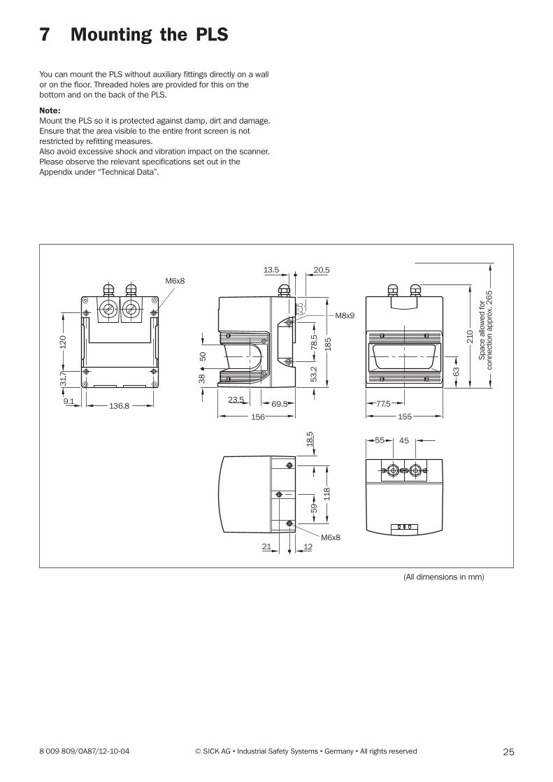
7 Mounting the PLS
You can mount the PLS without auxiliary fittings directly on a wall
or on the floor. Threaded holes are provided for this on the
bottom and on the back of the PLS.
Note:Mount the PLS so it is protected against damp, dirt and damage.
Ensure that the area visible to the entire front screen is not
restricted by refitting measures.
Also avoid excessive shock and vibration impact on the scanner.
Please observe the relevant specifications set out in the
Appendix under “Technical Data”.
(All dimensions in mm)
9.1136.8
23.569.5
156
13.5 20.5
77.5
155
4555
21 12
38
50
53
.2
18
5
31
.71
20 210
63
11
8
18
.55
97
8.5
M6x8
M8x9
M6x8
Sp
ace
allo
we
d f
or
co
nne
ctio
n a
pp
rox. 2
65
26 © SICK AG • Industrial Safety Systems • Germany • All rights reserved 8 009 809/OA87/12-10-04
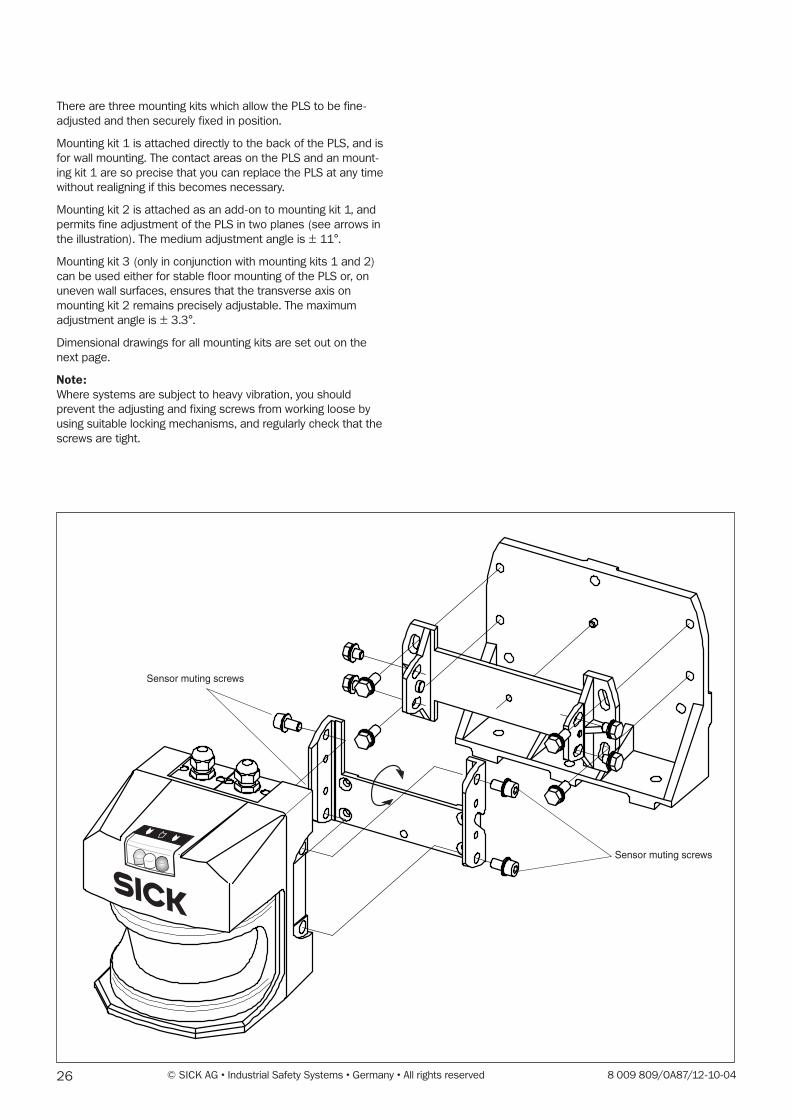
There are three mounting kits which allow the PLS to be fine-
adjusted and then securely fixed in position.
Mounting kit 1 is attached directly to the back of the PLS, and is
for wall mounting. The contact areas on the PLS and an mount-
ing kit 1 are so precise that you can replace the PLS at any time
without realigning if this becomes necessary.
Mounting kit 2 is attached as an add-on to mounting kit 1, and
permits fine adjustment of the PLS in two planes (see arrows in
the illustration). The medium adjustment angle is ± 11°.
Mounting kit 3 (only in conjunction with mounting kits 1 and 2)
can be used either for stable floor mounting of the PLS or, on
uneven wall surfaces, ensures that the transverse axis on
mounting kit 2 remains precisely adjustable. The maximum
adjustment angle is ± 3.3°.
Dimensional drawings for all mounting kits are set out on the
next page.
Note:Where systems are subject to heavy vibration, you should
prevent the adjusting and fixing screws from working loose by
using suitable locking mechanisms, and regularly check that the
screws are tight.
Sensor muting screws
Sensor muting screws
278 009 809/OA87/12-10-04 © SICK AG • Industrial Safety Systems • Germany • All rights reserved
46.5
31.5
16.5ø9
ø9
30
120
22.587.5
175
193.2
51
.8
10
27
1
220
16030
80
ø9
67
18
3
4660
71
DIN74 Am 6
10
6.1
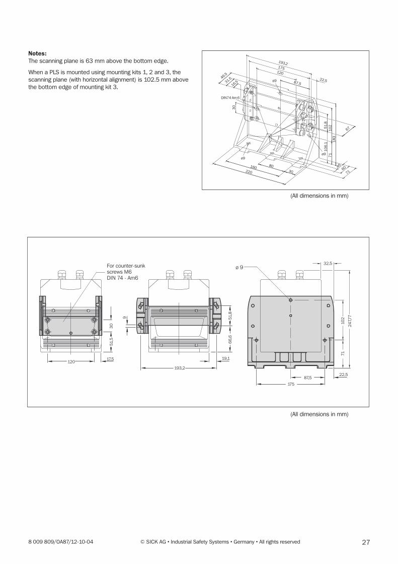
Notes:The scanning plane is 63 mm above the bottom edge.
When a PLS is mounted using mounting kits 1, 2 and 3, the
scanning plane (with horizontal alignment) is 102.5 mm above
the bottom edge of mounting kit 3.
(All dimensions in mm)
(All dimensions in mm)
12017,5
51
,53
0
193,2
19,1
66
,65
1,8
9
32,5
87,5
175
22,5
71
10
2
24
7,7
7
ø 9For counter-sunk
screws M6
DIN 74 - Am6

28 © SICK AG • Industrial Safety Systems • Germany • All rights reserved 8 009 809/OA87/12-10-04
8 Connecting up the PLS
The PLS is supplied with two plug-in connection boxes for the
power supply and interface. The electrical contact in each case
is made by a 9-pin sub-D connector screwed into the connec-
tion box.
Only when both connection boxes, with their seals under them,
are inserted flush with the housing and fixed with the side fixing
screws does the PLS conform to protection class IP65. If the
interface is not used, the connection box fitted with dummy
plugs must be used.
You can order pre-assembled connection sets in which the
power connector is fitted with an upward-routed cable. You can
find more details about the available connection sets in the
Appendix under “Accessories”.
If you assemble the connection yourself, you can choose
whether the connecting cable is routed out of the connector
housing upward or to the rear. The unused threaded hole in
either case must be plugged with a dummy plug.
Notes:Lay all wires and connecting cables so that they are protected
against damage.
lf you are using the PLS to protect hazardous areas: make sure
that the connected controller and all other devices also have the
necessary safety level.
Make sure the connection boxes for the power supply and the
interface are not mixed up when assembling the cable sets.
Do not drop the connection boxes with the connectors. The
sub-D connector could be pushed into the housing as a result.
� Check that the seals sit firmly on the connection boxes.
� Insert the connectors right-side up into the receptacles in
the PLS housing. Push the connectors lightly into the PLS
housing. You will know that a proper connection has been
made if the connectors terminate flush on the housing.
� Only then should you secure the connection boxes with the
hexagon socket screws on the sides.
Connecting up the PLS
Connection boxwith interface connector (X2.)
Connection boxwith power supply connector (X1.)
Cable connection can berouted either upwardor to the rear
298 009 809/OA87/12-10-04 © SICK AG • Industrial Safety Systems • Germany • All rights reserved
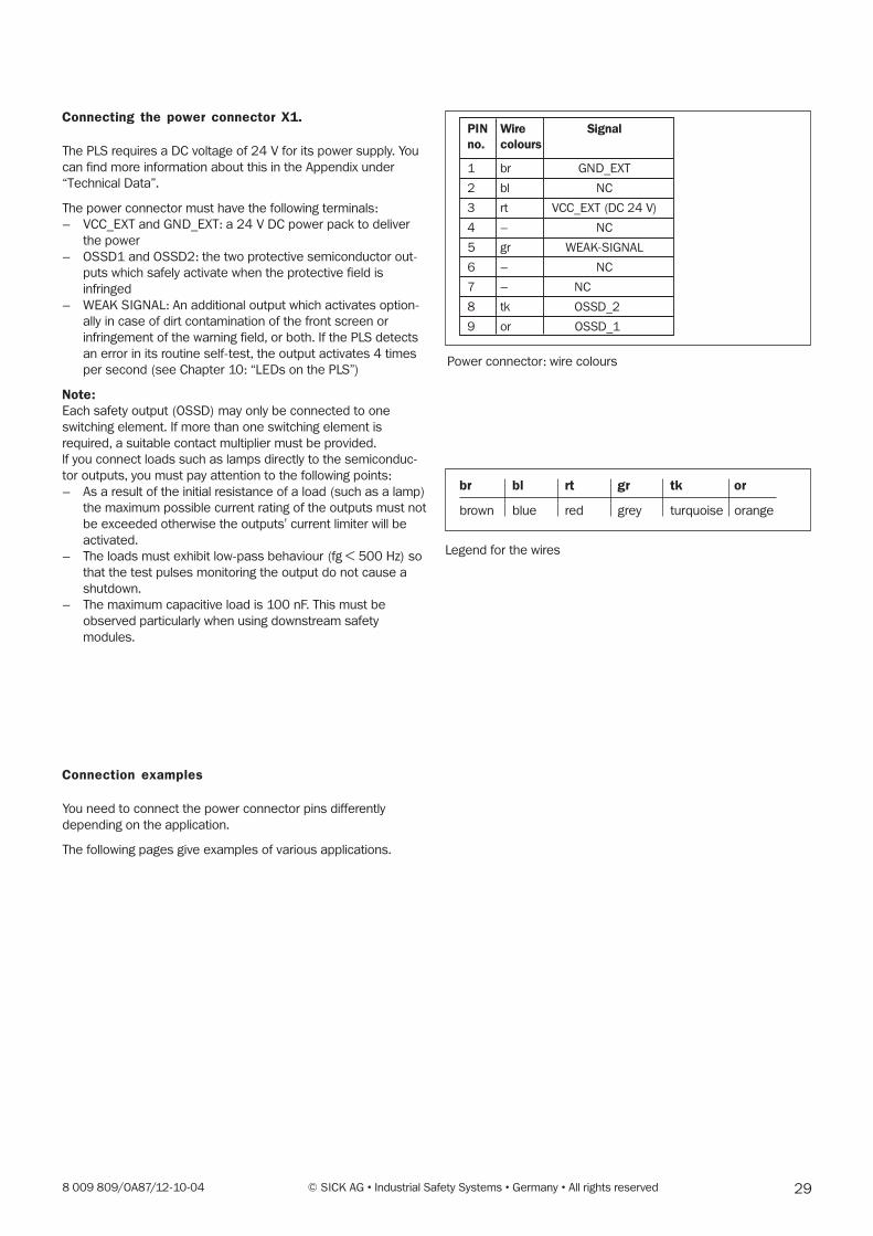
Connecting the power connector X1.
The PLS requires a DC voltage of 24 V for its power supply. You
can find more information about this in the Appendix under
“Technical Data”.
The power connector must have the following terminals:
– VCC_EXT and GND_EXT: a 24 V DC power pack to deliver
the power
– OSSD1 and OSSD2: the two protective semiconductor out-
puts which safely activate when the protective field is
infringed
– WEAK SIGNAL: An additional output which activates option-
ally in case of dirt contamination of the front screen or
infringement of the warning field, or both. If the PLS detects
an error in its routine self-test, the output activates 4 times
per second (see Chapter 10: “LEDs on the PLS”)
Note:Each safety output (OSSD) may only be connected to one
switching element. If more than one switching element is
required, a suitable contact multiplier must be provided.
lf you connect loads such as lamps directly to the semiconduc-
tor outputs, you must pay attention to the following points:
– As a result of the initial resistance of a load (such as a lamp)
the maximum possible current rating of the outputs must not
be exceeded otherwise the outputs' current limiter will be
activated.
– The loads must exhibit low-pass behaviour (fg < 500 Hz) so
that the test pulses monitoring the output do not cause a
shutdown.
– The maximum capacitive load is 100 nF. This must be
observed particularly when using downstream safety
modules.
Connection examples
You need to connect the power connector pins differently
depending on the application.
The following pages give examples of various applications.
Power connector: wire colours
PIN Wire Signalno. colours
1 br GND_EXT
2 bl NC
3 rt VCC_EXT (DC 24 V)
4 – NC
5 gr WEAK-SIGNAL
6 – NC
7 – NC
8 tk OSSD_2
9 or OSSD_1
Legend for the wires
br bl rt gr tk or
brown blue red grey turquoise orange
30 © SICK AG • Industrial Safety Systems • Germany • All rights reserved 8 009 809/OA87/12-10-04
0V
H2
5
1
8
3
9
PLS
+24V
S21Y2 A2Y1 14 24 34 42S22
S52
pilzPNOZ8
Y36 S12 A1 41332313
k2
k1
K1 K2
k2z
k1 k2
k1
z
x y
x1)
yX1.
X2.
LCU-X
X1 1
PEC1 D1 C2 D2 PE T3 T4
PEA2A1 To PE T13T14
PEC3 D3 C4 D4 14 24 32
T22X12T21 X21X22 13 23 31
5
1
8
3
9
PLS
0 V
PE
K1
+24V
3)
k1 k2
K2
k2z
k1 k2
k1
z
x y
x1)
y
X1.
X2.
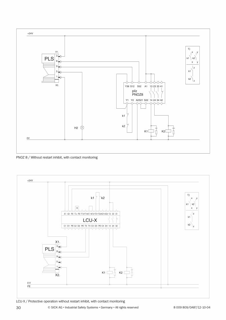
PNOZ 8 / Without restart inhibit, with contact monitoring
LCU-X / Protective operation without restart inhibit, with contact monitoring
318 009 809/OA87/12-10-04 © SICK AG • Industrial Safety Systems • Germany • All rights reserved
0V
K1
k1 k3
5
1
8
3
9
PLS
+24V
k2
k3
z
k1
z
k3k3
x y
x
k2k1
1)y
K2
k2 k3
K32)
k2
k1
4) 4) 4)
X1.
X2.
0V
H2
5
1
8
3
9
PLS
+24V
S1
S52
S21
pilzPNOZ8
Y2Y37 A2
Y36 S12
14 24 34 42S22
A1 41332313
k2
k1
K1 K2
k2z
k1 k2
k1
z
x y
x1)
yX1.
X2.
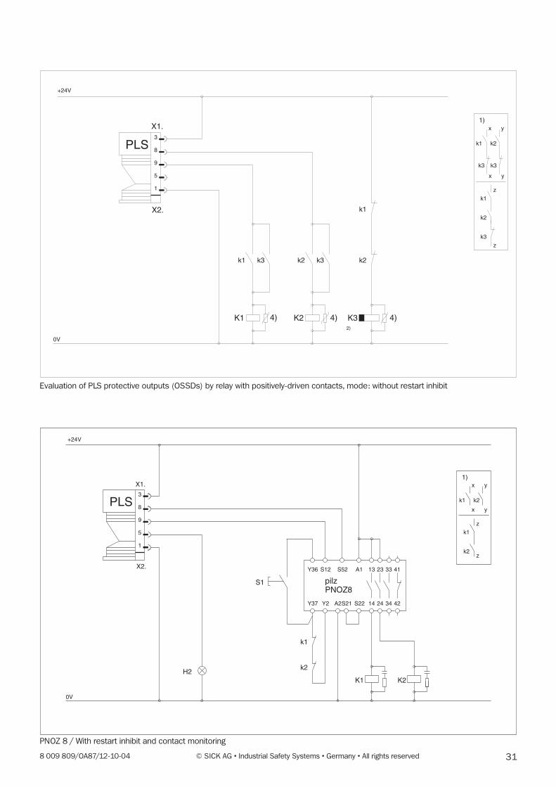
PNOZ 8 / With restart inhibit and contact monitoring
Evaluation of PLS protective outputs (OSSDs) by relay with positively-driven contacts, mode: without restart inhibit
32 © SICK AG • Industrial Safety Systems • Germany • All rights reserved 8 009 809/OA87/12-10-04
0V
K1
k1 k3
5
1
8
3
9
PLS
+24V
k2
k3
z
k1
z
k3k3
x y
x
k2k1
1)y
K2
k2 k3
K3
k2
k1
k3
S1
4)4) 4)
X1.
X2.
LCU-X
X1 1
PEC1 D1 C2 D2 PE T3 T4
PEA2A1 To PE T13T14
PEC3 D3 C4 D4 14 24 32
T22X12T21 X21X22 13 23 31
5
1
8
3
9
PLS
0 V
PE
K1
+24V
3)
S1k1 k2
K2
k2z
k1 k2
k1
z
x y
x1)
y
X1.
X2.
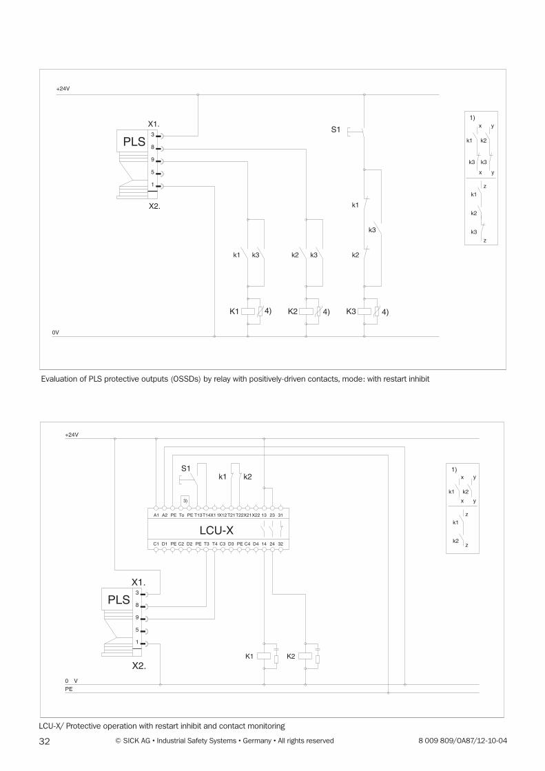
Evaluation of PLS protective outputs (OSSDs) by relay with positively-driven contacts, mode: with restart inhibit
LCU-X/ Protective operation with restart inhibit and contact monitoring

338 009 809/OA87/12-10-04 © SICK AG • Industrial Safety Systems • Germany • All rights reserved
Information about the connection examples
Note:Use only relays with positively-driven relays. The FC elements
switched in parallel with the contactors are for arc suppression.
1) Output circuits. These contacts are to be inserted into the
control unit so that the hazardous state is eliminated when
the output circuit is opened. In categories 3 and 4 in
accordance with EN 954-1 this insertion must be in two
channels (x, y paths). Single-channel insertion into the
control path (z path) is only possible with single-channel
control and taking account of the risk analysis.
2) To safeguard activation of K1 and K2 during the switchover
phase, K3 should be executed with a release delay in
accordance with the contactors used and the operating
voltage.
The control circuits must be provided with a selective over-
current protection device (fuse).
3) The potential equalisation must be provided if the OV
potential of the power supply unit is not connected with the
protective conductor (PE) (VDE 0160).
4) Voltage-dependent resistors for maximum operating AC
voltage VRMS
= 25 V
34 © SICK AG • Industrial Safety Systems • Germany • All rights reserved 8 009 809/OA87/12-10-04
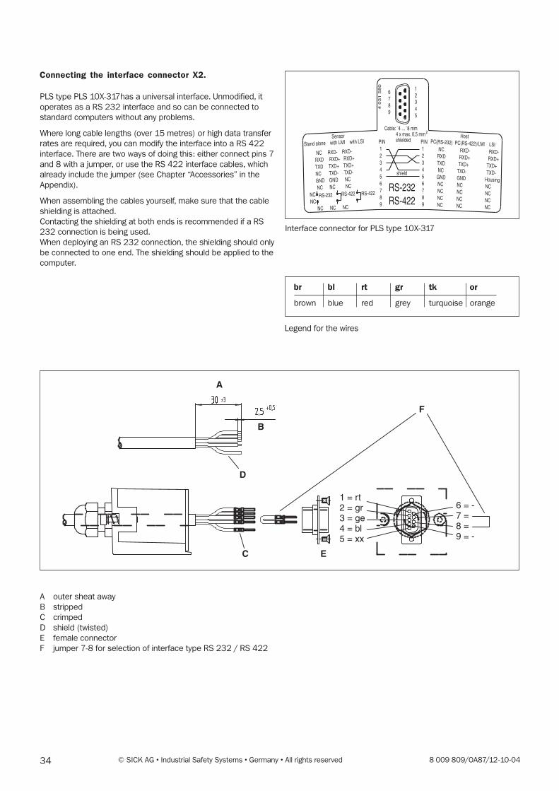
Connecting the interface connector X2.
PLS type PLS 10X-317has a universal interface. Unmodified, it
operates as a RS 232 interface and so can be connected to
standard computers without any problems.
Where long cable lengths (over 15 metres) or high data transfer
rates are required, you can modify the interface into a RS 422
interface. There are two ways of doing this: either connect pins 7
and 8 with a jumper, or use the RS 422 interface cables, which
already include the jumper (see Chapter “Accessories” in the
Appendix).
When assembling the cables yourself, make sure that the cable
shielding is attached.
Contacting the shielding at both ends is recommended if a RS
232 connection is being used.
When deploying an RS 232 connection, the shielding should only
be connected to one end. The shielding should be applied to the
computer.
Interface connector for PLS type 10X-317
PIN 1 2 3 4 5 6 7 8 9
PIN 1 2 3 4 5 6 7 8 9
shield
RS-232RS-422
Host
6789
12345
NC RXD- RXD-
RXD RXD+ RXD+
TXD TXD+ TXD+
NC TXD- TXD-
GND GND NC
NC NC NC
NCNC
NC NC NC
Sensor
NC RXD- RXD-RXD RXD+ RXD+TXD TXD+ TXD+ NC TXD- TXD-GND GND Housing NC NC NC NC NC NC NC NC NC NC NC NC
Cable: ¯4 ... ¯8 mm4 x max. 0,5 mmshielded
2
4 0
31 5
80
Stand alone with LMI with LSI PC(RS-232) PC(RS-422)/LMI LSI
RS-232 RS-422 RS-422
Legend for the wires
br bl rt gr tk or
brown blue red grey turquoise orange
F
A
B
D
C E
1 = rt2 = gr3 = ge4 = bl5 = xx
6 = -7 =8 =9 = -
A outer sheat away
B stripped
C crimped
D shield (twisted)
E female connector
F jumper 7-8 for selection of interface type RS 232 / RS 422

358 009 809/OA87/12-10-04 © SICK AG • Industrial Safety Systems • Germany • All rights reserved
Short-term connection to a PC
You normally only connect the PC to the sensor for program-
ming purposes, for example when using the sensor to protect a
hazardous area. All settings and fields remain stored in the sen-
sor after the PLS is disconnected from the PC, until changed
again by you. The sensor will not lose its data even in the event
of a power failure.
To connect to the PC, use an interface cable (refer to the Ap-
pendix under “Accessories”).
Note:If you want to connect a sensor to a computer by a RS 422 in-
terface, you must use a suitable cable. Refer to the notes on
switching interfaces on the previous page.
� Remove the connection box over the interface socket on the
PLS.
Note:When the connection box has been loosened, the PLS conforms
only to protection class IP 40.
� Connect the sensor interface to the PC.
� Programme the PLS. For detailed information refer to the PSI
user software description as from Chapter 9.
� Detach the interface cable from the PLS.
� Reconnect the connection box over the interface socket and
screw it in tight.
Note:The pin assignment of an RS 422 interface is not standardised.
Compare the pin assignment of the connecting cable with the
one an the PC and adapt it accordingly.
Permanent connection to an evaluation computer
If you want to continuously evaluate the measurement data of
the PLS using the RS 422 interface (for example, because of the
higher data transfer rate) you must connect the PLS perma-
nently to an evaluation computer.
� Wire the 9-pin sub-D connector in the connection box with a
suitable cable (RS 422 twisted pair).
You can choose whether to route the cable out of the box
upward or to the rear.
Note:The cable outlet is PG 9 size, and is suitable for all cable
diameters from 4 to 8 mm.
� Plug the connection box into the PLS and screw it in tight.
� Lay the cable permanently to the evaluation computer or to
the vehicle’s on-board computer.
Note:Lay all cables so that they are protected against damage.

36 © SICK AG • Industrial Safety Systems • Germany • All rights reserved 8 009 809/OA87/12-10-04
9 Programming the PLS with the User Software
9.1 Installing the user software
Note:
This chapter describes how to programme a PLS proximity laser
scanner.
The Proximity Laser Scanner PLS 10X-317 can only be
programmed and commissioned using the PLS user software
version 8.62.
lf you have older PLS user software installed on your PC which
you want to continue using, specify a different programme
directory/folder when installing the new PLS software.
System requirements
Please observe the respective hardware requirements of the
operating systems listed here.
– min. 4 MB available hard disk capacity
– Windows 95TM, Windows 98TM, Windows NTTM 4/SP4 or
Windows 2000TM
– min. 80486 processor
– min. 4 MB main memory
– Colour monitor recommended
– Installed graphic printer driver
When installing your PLS user software you are guided by the
installation pro-gramme. All you have to do is start the
programme as follows:
� Boot your PC.
� Insert the PLS programme disk in the disk drive of your PC.
� Select Run in the Start menu.
� Select and run the programme “Install.exe”.
� If necessary, enter the programme directory/folder where
you want the new PLS software to be installed.
� Follow the on-screen instructions.
After the installation is finished a message box appears to tell
you that the setup has been completed successfully.
The PLS user software is now installed. You can run it at any time
by clicking on its icon.
378 009 809/OA87/12-10-04 © SICK AG • Industrial Safety Systems • Germany • All rights reserved
9.2 What to do
Note:When the programme starts you are automatically logged on as
the machine operator. As such, you can poll data but cannot
transmit any.
To be able to transmit configuration data and monitoring areas
to the PLS, you must log an as an “Authorised Client”. How to log
on is described in Section 9.3.
In the status bar at the bottom of the screen you will see a
colour code for the on-screen display of the protective and
warning fields.
Essential steps
In creating a new configuration you are guided by the PLS user
software. It guides you through the following steps:
� Configure hardware:You log the PLS on and define the restart inhibit mode of the
protective outputs (OSSDs). You select the number of
multiple evaluations and define whether you are using the
sensor for area protection or for protection on a vehicle. You
also define the switching behaviour of the “Weak Signal”
output.
� Define monitoring range:You define the range to be monitored by the PLS. If you wish,
you can also determine the shape and size of the protective
and warning fields here.
� Send configuration to PLS:You now transmit all the configuration settings you have
made to the PLS. You must be logged on as an “Authorised
Client” to be able to do this.
� Edit monitoring range:Here, if you wish, you have the chance to alter the shape
and size of the protective and warning fields.
� Send monitoring range to PLS:Finally you transmit the protective and warning fields to the
PLS. For this too, you must be logged on as an “Authorised
Client”.
When you have completed these steps the PLS system is ready
for operation.
Note:Change the logon password to protect your PLS systemagainst manipulation (see Chapter 9.13).Log your configuration data stored in the PLS, and back up the
configuration on the hard disk or on a floppy disk (see
Section 9.12).
Other options
In addition to the essential steps, you can use a number of other
options when configuring your PLS system.
– Edit fields:To edit the protective and warning fields the PLS user
software provides you with a number of useful edit functions.
– Teach-in and check protective field:In the teach-in process you run over the contours of the
desired protective field with the sensor active, and the PLS
stores the learned contour. You have to check learned
protective fields.
You can also edit a learned protective field subsequently, just
like any other segmented field.
– Monitor protective field:You can monitor the protective and warning fields during
operation using a connected PC. You can also store the
defined space contours of the sensor as a check.
– Check settings:You can view, check and print all configuration settings in a
page view.
– Receive and store configuration:You can receive and print the configuration data stored in the
PLS. You can save any configuration to the hard disk or to a
floppy disk.
– Change password:To protect your PLS against manipulation, you should change
the logon password.
– Change screen view:You can zoom in, zoom out or move the screen view, for
example.
– Interrogate fault memory (system diagnosis):For troubleshooting purposes you can interrogate the fault
memory of the PLS.
38 © SICK AG • Industrial Safety Systems • Germany • All rights reserved 8 009 809/OA87/12-10-04
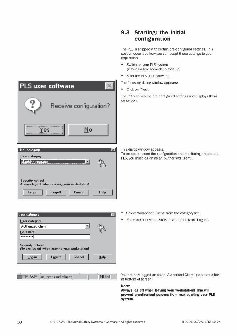
9.3 Starting: the initialconfiguration
The PLS is shipped with certain pre-configured settings. This
section describes how you can adapt those settings to your
application.
� Switch on your PLS system
(it takes a few seconds to start up).
� Start the PLS user software.
The following dialog window appears:
� Click on “Yes”.
The PC receives the pre-configured settings and displays them
on-screen.
This dialog window appears.
To be able to send the configuration and monitoring area to the
PLS, you must log on as an “Authorised Client”.
� Select “Authorised Client” from the category list.
� Enter the password “SICK_PLS” and click on “Logon”.
You are now logged on as an “Authorised Client” (see status bar
at bottom of screen).
Note:Always log off when leaving your workstation! This willprevent unauthorised persons from manipulating your PLSsystem.
398 009 809/OA87/12-10-04 © SICK AG • Industrial Safety Systems • Germany • All rights reserved
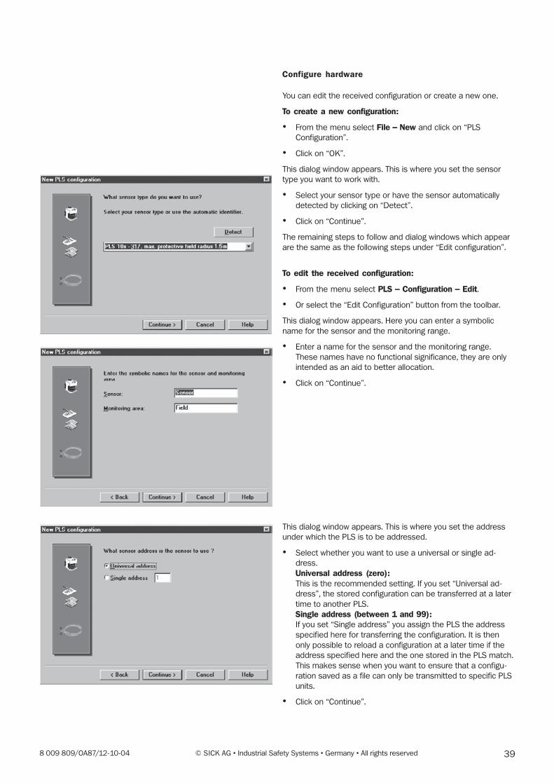
Configure hardware
You can edit the received configuration or create a new one.
To create a new configuration:
� From the menu select File � New and click on “PLS
Configuration”.
� Click on “OK”.
This dialog window appears. This is where you set the sensor
type you want to work with.
� Select your sensor type or have the sensor automatically
detected by clicking on “Detect”.
� Click on “Continue”.
The remaining steps to follow and dialog windows which appear
are the same as the following steps under “Edit configuration”.
To edit the received configuration:
� From the menu select PLS � Configuration � Edit.
� Or select the “Edit Configuration” button from the toolbar.
This dialog window appears. Here you can enter a symbolic
name for the sensor and the monitoring range.
� Enter a name for the sensor and the monitoring range.
These names have no functional significance, they are only
intended as an aid to better allocation.
� Click on “Continue”.
This dialog window appears. This is where you set the address
under which the PLS is to be addressed.
� Select whether you want to use a universal or single ad-
dress.
Universal address (zero):This is the recommended setting. If you set “Universal ad-
dress”, the stored configuration can be transferred at a later
time to another PLS.
Single address (between 1 and 99):If you set “Single address” you assign the PLS the address
specified here for transferring the configuration. It is then
only possible to reload a configuration at a later time if the
address specified here and the one stored in the PLS match.
This makes sense when you want to ensure that a configu-
ration saved as a file can only be transmitted to specific PLS
units.
� Click on “Continue”.
40 © SICK AG • Industrial Safety Systems • Germany • All rights reserved 8 009 809/OA87/12-10-04
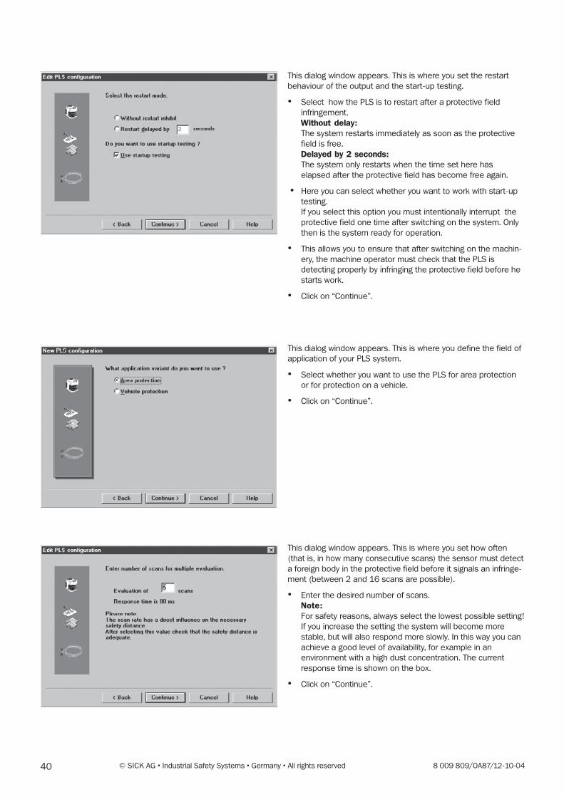
This dialog window appears. This is where you set the restart
behaviour of the output and the start-up testing.
� Select how the PLS is to restart after a protective field
infringement.
Without delay:The system restarts immediately as soon as the protective
field is free.
Delayed by 2 seconds:The system only restarts when the time set here has
elapsed after the protective field has become free again.
� Here you can select whether you want to work with start-up
testing.
If you select this option you must intentionally interrupt the
protective field one time after switching on the system. Only
then is the system ready for operation.
� This allows you to ensure that after switching on the machin-
ery, the machine operator must check that the PLS is
detecting properly by infringing the protective field before he
starts work.
� Click on “Continue”.
This dialog window appears. This is where you define the field of
application of your PLS system.
� Select whether you want to use the PLS for area protection
or for protection on a vehicle.
� Click on “Continue”.
This dialog window appears. This is where you set how often
(that is, in how many consecutive scans) the sensor must detect
a foreign body in the protective field before it signals an infringe-
ment (between 2 and 16 scans are possible).
� Enter the desired number of scans.
Note:For safety reasons, always select the lowest possible setting!
If you increase the setting the system will become more
stable, but will also respond more slowly. In this way you can
achieve a good level of availability, for example in an
environment with a high dust concentration. The current
response time is shown on the box.
� Click on “Continue”.
418 009 809/OA87/12-10-04 © SICK AG • Industrial Safety Systems • Germany • All rights reserved
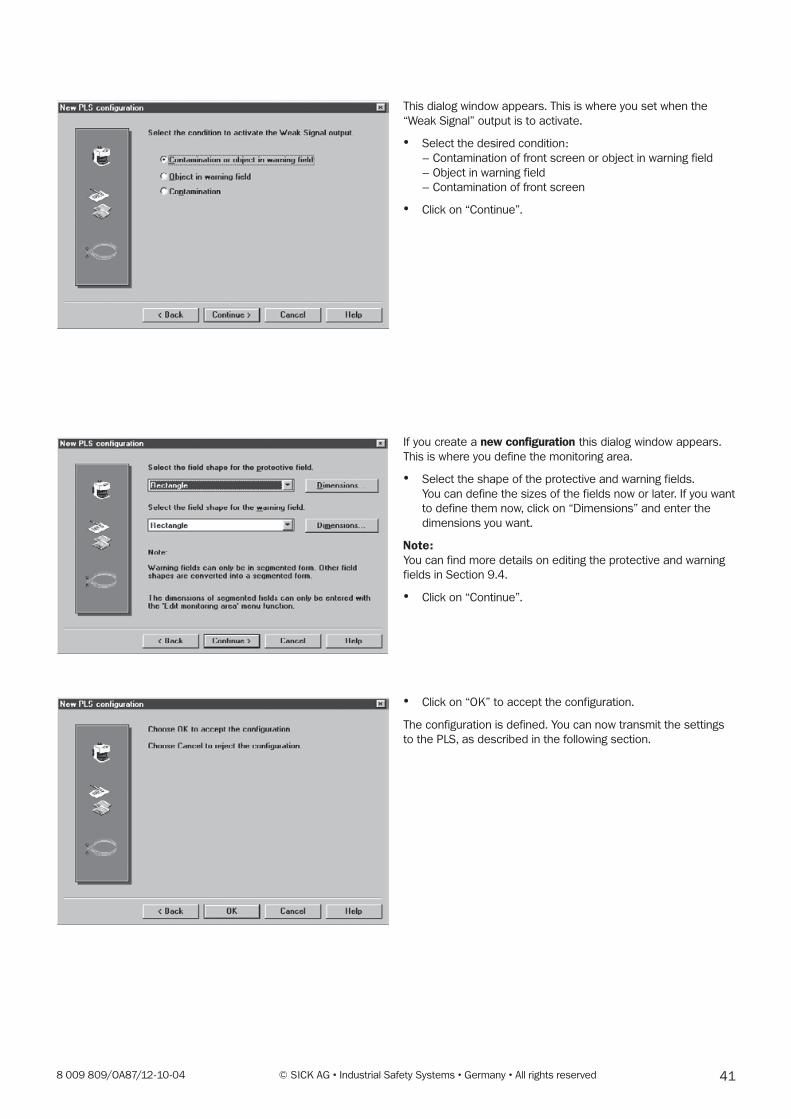
This dialog window appears. This is where you set when the
“Weak Signal” output is to activate.
� Select the desired condition:
– Contamination of front screen or object in warning field
– Object in warning field
– Contamination of front screen
� Click on “Continue”.
If you create a new configuration this dialog window appears.
This is where you define the monitoring area.
� Select the shape of the protective and warning fields.
You can define the sizes of the fields now or later. If you want
to define them now, click on “Dimensions” and enter the
dimensions you want.
Note:You can find more details on editing the protective and warning
fields in Section 9.4.
� Click on “Continue”.
� Click on “OK” to accept the configuration.
The configuration is defined. You can now transmit the settings
to the PLS, as described in the following section.
42 © SICK AG • Industrial Safety Systems • Germany • All rights reserved 8 009 809/OA87/12-10-04
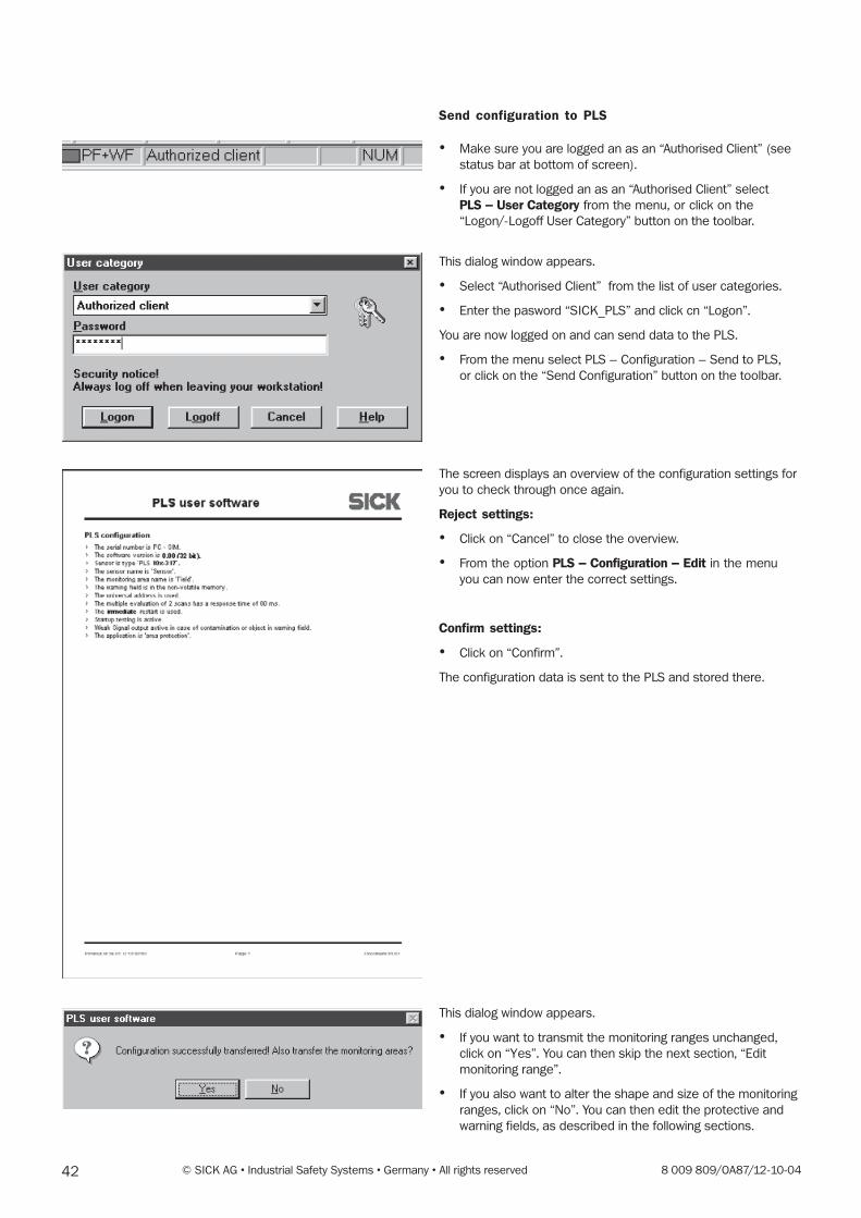
Send configuration to PLS
� Make sure you are logged an as an “Authorised Client” (see
status bar at bottom of screen).
� If you are not logged an as an “Authorised Client” select
PLS � User Category from the menu, or click on the
“Logon/-Logoff User Category” button on the toolbar.
This dialog window appears.
� Select “Authorised Client” from the list of user categories.
� Enter the pasword “SICK_PLS” and click cn “Logon”.
You are now logged on and can send data to the PLS.
� From the menu select PLS – Configuration – Send to PLS,
or click on the “Send Configuration” button on the toolbar.
The screen displays an overview of the configuration settings for
you to check through once again.
Reject settings:
� Click on “Cancel” to close the overview.
� From the option PLS � Configuration � Edit in the menu
you can now enter the correct settings.
Confirm settings:
� Click on “Confirm”.
The configuration data is sent to the PLS and stored there.
This dialog window appears.
� If you want to transmit the monitoring ranges unchanged,
click on “Yes”. You can then skip the next section, “Edit
monitoring range”.
� If you also want to alter the shape and size of the monitoring
ranges, click on “No”. You can then edit the protective and
warning fields, as described in the following sections.
438 009 809/OA87/12-10-04 © SICK AG • Industrial Safety Systems • Germany • All rights reserved
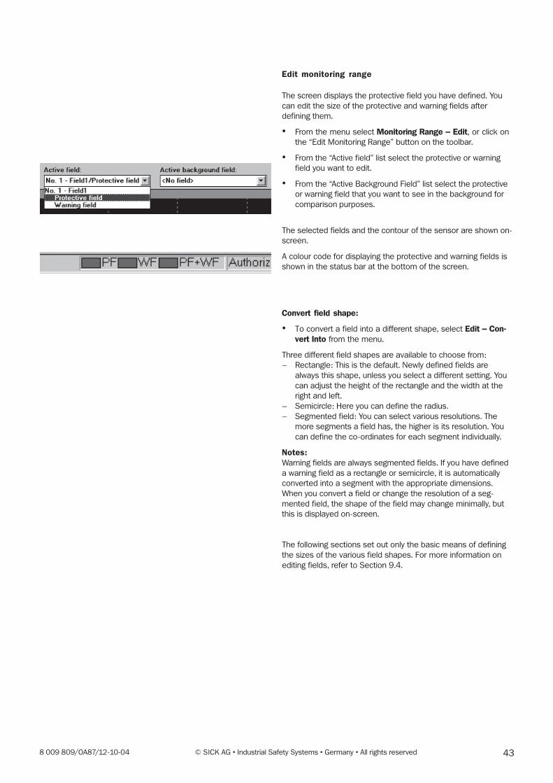
Edit monitoring range
The screen displays the protective field you have defined. You
can edit the size of the protective and warning fields after
defining them.
� From the menu select Monitoring Range � Edit, or click on
the “Edit Monitoring Range” button on the toolbar.
� From the “Active field” list select the protective or warning
field you want to edit.
� From the “Active Background Field” list select the protective
or warning field that you want to see in the background for
comparison purposes.
The selected fields and the contour of the sensor are shown on-
screen.
A colour code for displaying the protective and warning fields is
shown in the status bar at the bottom of the screen.
Convert field shape:
� To convert a field into a different shape, select Edit � Con-vert Into from the menu.
Three different field shapes are available to choose from:
– Rectangle: This is the default. Newly defined fields are
always this shape, unless you select a different setting. You
can adjust the height of the rectangle and the width at the
right and left.
– Semicircle: Here you can define the radius.
– Segmented field: You can select various resolutions. The
more segments a field has, the higher is its resolution. You
can define the co-ordinates for each segment individually.
Notes:Warning fields are always segmented fields. If you have defined
a warning field as a rectangle or semicircle, it is automatically
converted into a segment with the appropriate dimensions.
When you convert a field or change the resolution of a seg-
mented field, the shape of the field may change minimally, but
this is displayed on-screen.
The following sections set out only the basic means of defining
the sizes of the various field shapes. For more information on
editing fields, refer to Section 9.4.
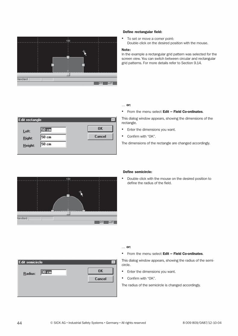
44 © SICK AG • Industrial Safety Systems • Germany • All rights reserved 8 009 809/OA87/12-10-04
Define rectangular field:
� To set or move a comer point:
Double-click on the desired position with the mouse.
Note:In the example a rectangular grid pattern was selected for the
screen view. You can switch between circular and rectangular
grid patterns. For more details refer to Section 9.14.
� or:
� From the menu select Edit � Field Co-ordinates.
This dialog window appears, showing the dimensions of the
rectangle.
� Enter the dimensions you want.
� Confirm with “OK”.
The dimensions of the rectangle are changed accordingly.
Define semicircle:
� Double-click with the mouse on the desired position to
define the radius of the field.
� or:
� From the menu select Edit � Field Co-ordinates.
This dialog window appears, showing the radius of the semi-
circle.
� Enter the dimensions you want.
� Confirm with “OK”.
The radius of the semicircle is changed accordingly.
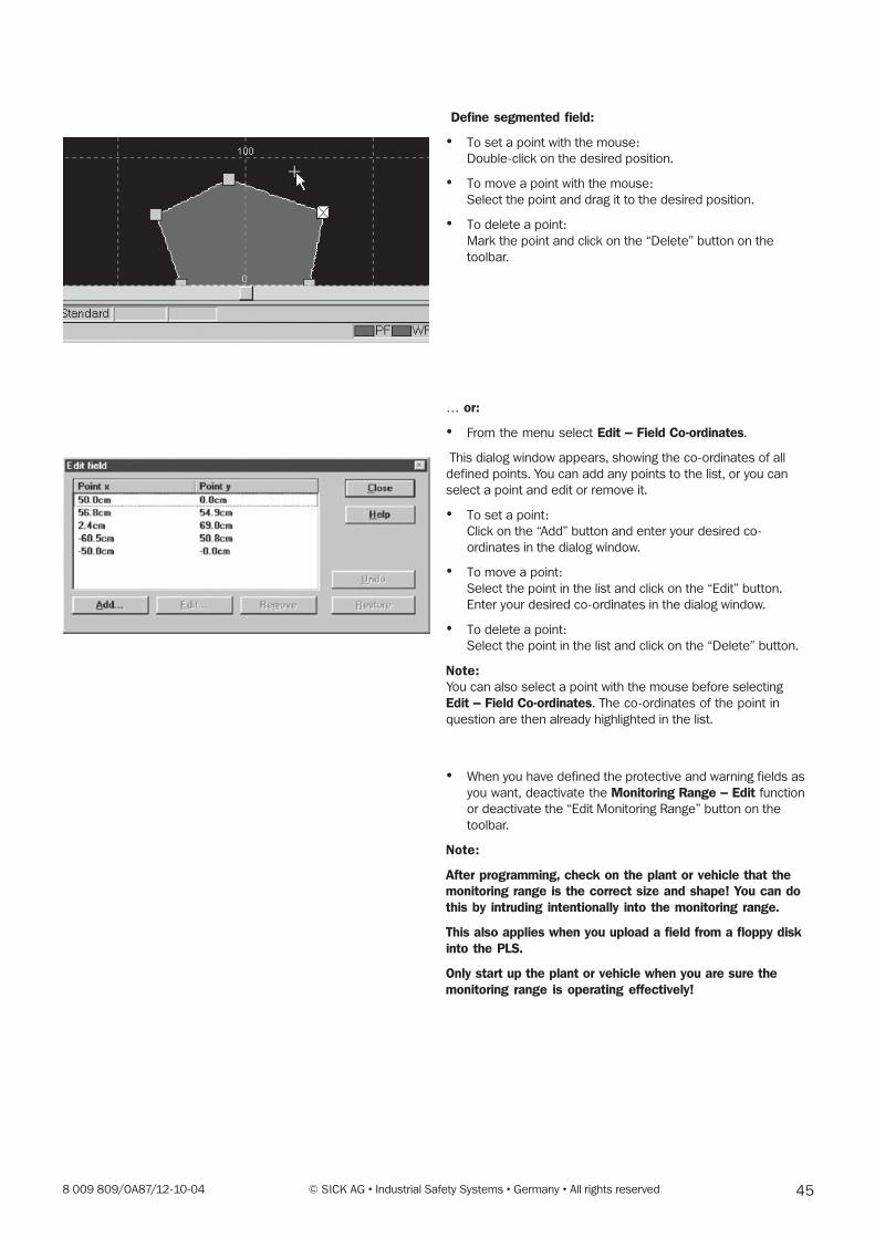
458 009 809/OA87/12-10-04 © SICK AG • Industrial Safety Systems • Germany • All rights reserved
Define segmented field:
� To set a point with the mouse:
Double-click on the desired position.
� To move a point with the mouse:
Select the point and drag it to the desired position.
� To delete a point:
Mark the point and click on the “Delete” button on the
toolbar.
� or:
� From the menu select Edit � Field Co-ordinates.
This dialog window appears, showing the co-ordinates of all
defined points. You can add any points to the list, or you can
select a point and edit or remove it.
� To set a point:
Click on the “Add” button and enter your desired co-
ordinates in the dialog window.
� To move a point:
Select the point in the list and click on the “Edit” button.
Enter your desired co-ordinates in the dialog window.
� To delete a point:
Select the point in the list and click on the “Delete” button.
Note:You can also select a point with the mouse before selecting
Edit � Field Co-ordinates. The co-ordinates of the point in
question are then already highlighted in the list.
� When you have defined the protective and warning fields as
you want, deactivate the Monitoring Range � Edit function
or deactivate the “Edit Monitoring Range” button on the
toolbar.
Note:
After programming, check on the plant or vehicle that themonitoring range is the correct size and shape! You can dothis by intruding intentionally into the monitoring range.
This also applies when you upload a field from a floppy diskinto the PLS.
Only start up the plant or vehicle when you are sure themonitoring range is operating effectively!
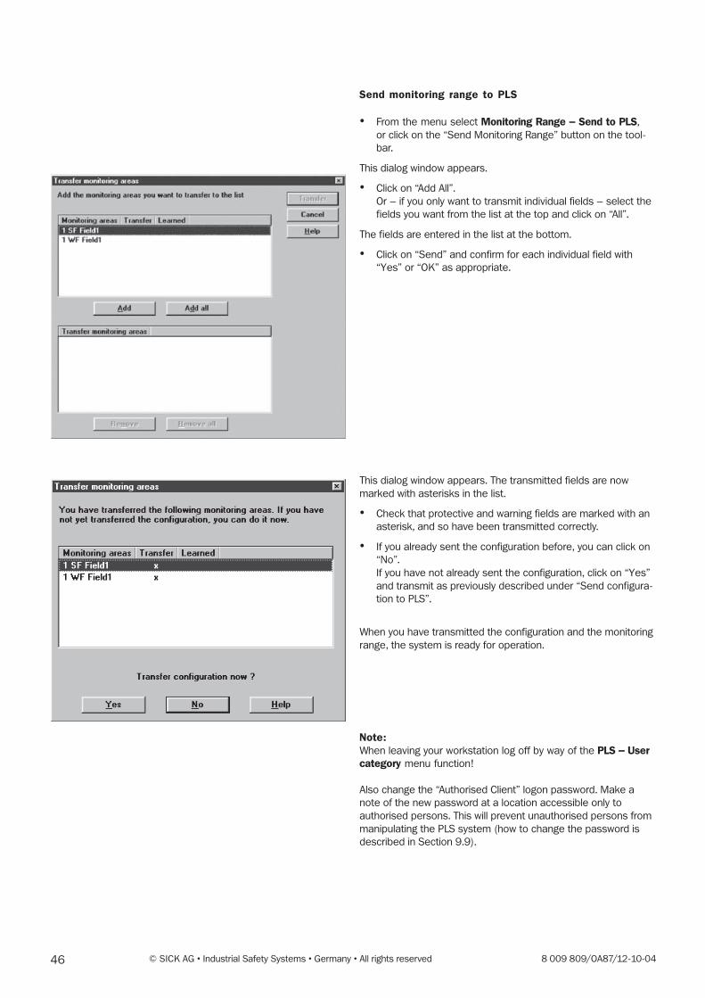
46 © SICK AG • Industrial Safety Systems • Germany • All rights reserved 8 009 809/OA87/12-10-04
Send monitoring range to PLS
� From the menu select Monitoring Range � Send to PLS,
or click on the “Send Monitoring Range” button on the tool-
bar.
This dialog window appears.
� Click on “Add All”.
Or – if you only want to transmit individual fields – select the
fields you want from the list at the top and click on “All”.
The fields are entered in the list at the bottom.
� Click on “Send” and confirm for each individual field with
“Yes” or “OK” as appropriate.
This dialog window appears. The transmitted fields are now
marked with asterisks in the list.
� Check that protective and warning fields are marked with an
asterisk, and so have been transmitted correctly.
� If you already sent the configuration before, you can click on
“No”.
If you have not already sent the configuration, click on “Yes”
and transmit as previously described under “Send configura-
tion to PLS”.
When you have transmitted the configuration and the monitoring
range, the system is ready for operation.
Note:When leaving your workstation log off by way of the PLS � Usercategory menu function!
Also change the “Authorised Client” logon password. Make a
note of the new password at a location accessible only to
authorised persons. This will prevent unauthorised persons from
manipulating the PLS system (how to change the password is
described in Section 9.9).
478 009 809/OA87/12-10-04 © SICK AG • Industrial Safety Systems • Germany • All rights reserved
9.4 Edit/dimension fields
Section 9.3 describes the basic way to edit a protective or
warning field. You can use rectangular, semicircular or multiply-
segmented fields. You can draw the fields either by using the
mouse or by typing in their co-ordinates.
This chapter describes the additional options of defining the size
and shape of the protective and warning fields for your
application. Various edit functions will assist you in drawing up
the fields.
A colour code for displaying the protective and warning fields is
shown in the status bar at the bottom of the screen.
Note:After programming, check on the plant or vehicle that the
monitoring range is the correct size and shape! You can do this
by intruding intentionally into the monitoring range.
Only start up the plant or vehicle when you are sure the monitor-
ing range is operating effectively!
Convert field shape:
You can convert a field into a different shape – for example, a
rectangular field into a segmented field.
� Select Edit � Convert Into from the menu.
Three different field shapes are available to choose from
– Rectangle: This is the default. Newly defined fields are
always this shape, unless you select a different setting. You
can adjust the height of the rectangle and the width at the
right and left.
– Semicircle: Here you can define the radius.
– Segmented field: You can select various resolutions. The
more segments a field has, the higher is its resolution. You
can define the co-ordinates for each segment individually.
Note:Please observe that during conversion slight deviations in the
protective field co-ordinates may occur, which are nonetheless
visible on-screen.
Warning fields are always segmented fields. If you have defined
a warning field as a rectangle or semicircle, it is automatically
converted into a segment with the appropriate dimensions.
Change scale of a segmented field
When you have defined a segmented field you can enlarge or
reduce it in scale.
� Select Edit � Select All to select all the points in the field.
� Pick up one of the marked points with the mouse and drag
the field to the size you want.
Each point is dragged on the measuring beam of its sensor
away from or towards the zero point as appropriate.
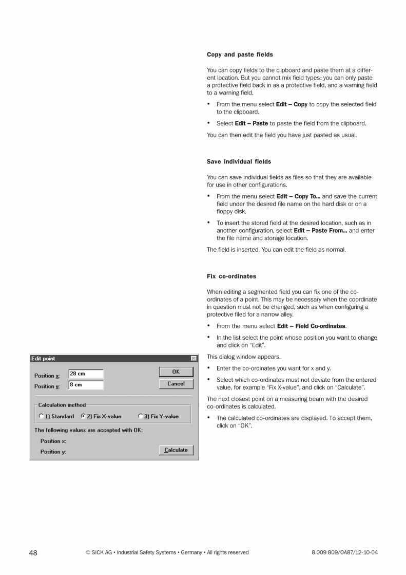
48 © SICK AG • Industrial Safety Systems • Germany • All rights reserved 8 009 809/OA87/12-10-04
Copy and paste fields
You can copy fields to the clipboard and paste them at a differ-
ent location. But you cannot mix field types: you can only paste
a protective field back in as a protective field, and a warning field
to a warning field.
� From the menu select Edit � Copy to copy the selected field
to the clipboard.
� Select Edit � Paste to paste the field from the clipboard.
You can then edit the field you have just pasted as usual.
Save individual fields
You can save individual fields as files so that they are available
for use in other configurations.
� From the menu select Edit � Copy To... and save the current
field under the desired file name on the hard disk or on a
floppy disk.
� To insert the stored field at the desired location, such as in
another configuration, select Edit � Paste From... and enter
the file name and storage location.
The field is inserted. You can edit the field as normal.
Fix co-ordinates
When editing a segmented field you can fix one of the co-
ordinates of a point. This may be necessary when the coordinate
in question must not be changed, such as when configuring a
protective filed for a narrow alley.
� From the menu select Edit � Field Co-ordinates.
� In the list select the point whose position you want to change
and click on “Edit”.
This dialog window appears.
� Enter the co-ordinates you want for x and y.
� Select which co-ordinates must not deviate from the entered
value, for example “Fix X-value”, and click on “Calculate”.
The next closest point on a measuring beam with the desired
co-ordinates is calculated.
� The calculated co-ordinates are displayed. To accept them,
click on “OK”.
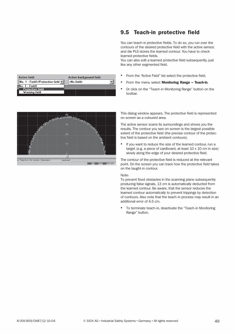
498 009 809/OA87/12-10-04 © SICK AG • Industrial Safety Systems • Germany • All rights reserved
9.5 Teach-in protective field
You can teach-in protective fields. To do so, you run over the
contours of the desired protective field with the active sensor,
and die PLS stores the learned contour. You have to check
learned protective fields.
You can also edit a learned protective field subsequently, just
like any other segmented field.
� From the “Active Field” list select the protective field.
� From the menu select Monitoring Range � Teach-in.
� Or click on the “Teach-in Monitoring Range” button on the
toolbar.
This dialog window appears. The protective field is represented
on-screen as a coloured area.
The active sensor scans its surroundings and shows you the
results. The contour you see on-screen is the largest possible
extent of the protective field (the precise contour of the protec-
tive field is based on the ambient contours).
� If you want to reduce the size of the learned contour, run a
target (e.g. a piece of cardboard, at least 10 x 10 cm in size)
slowly along the edge of your desired protective field.
The contour of the protective field is reduced at the relevant
point. On the screen you can track how the protective field takes
on the taught-in contour.
Note:
To prevent fixed obstacles in the scanning plane subsequently
producing false signals, 13 cm is automatically deducted from
the learned contour. Be aware, that the sensor reduces the
learned contour automatically to prevent trippings by detection
of contours. Also note that the teach-in process may result in an
additional error of 4.5 cm.
� To terminate teach-in, deactivate the “Teach-in Monitoring
Range” button.
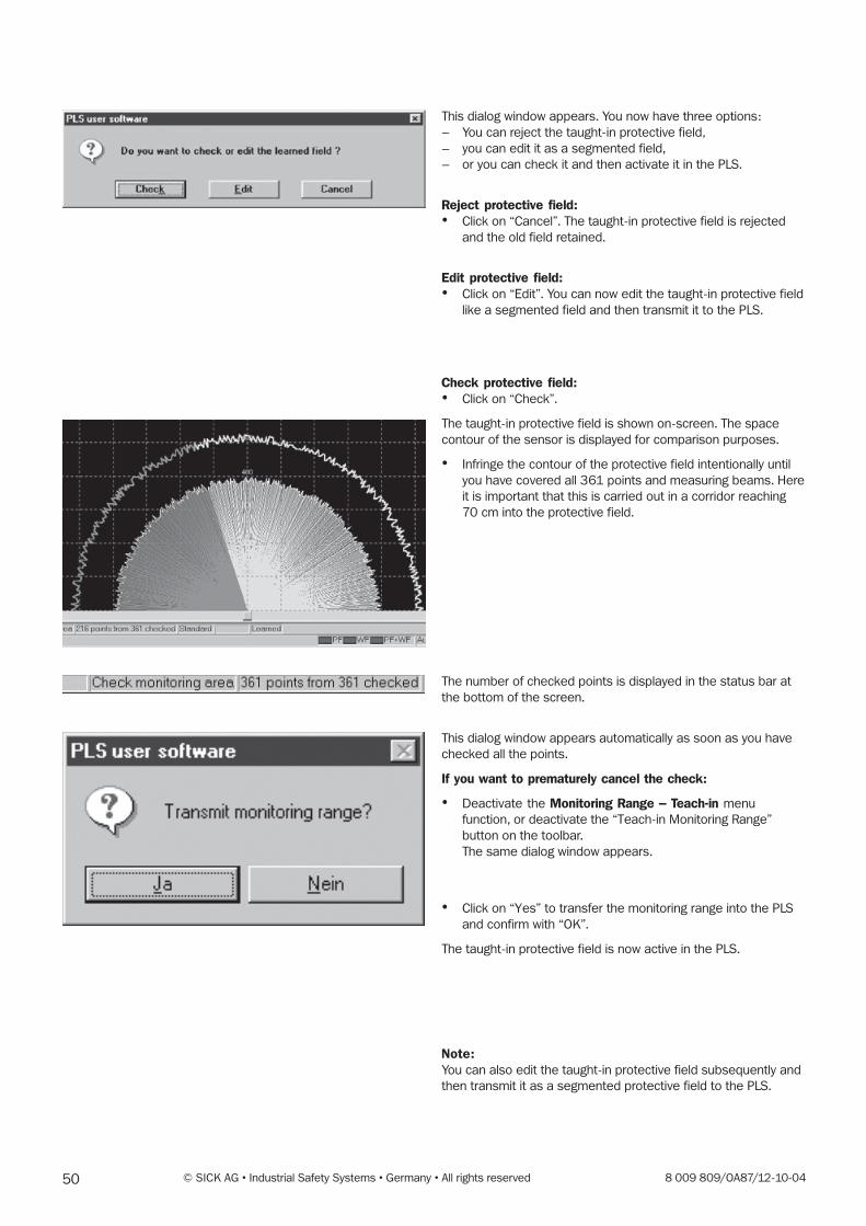
50 © SICK AG • Industrial Safety Systems • Germany • All rights reserved 8 009 809/OA87/12-10-04
This dialog window appears. You now have three options:
– You can reject the taught-in protective field,
– you can edit it as a segmented field,
– or you can check it and then activate it in the PLS.
Reject protective field:� Click on “Cancel”. The taught-in protective field is rejected
and the old field retained.
Edit protective field:� Click on “Edit”. You can now edit the taught-in protective field
like a segmented field and then transmit it to the PLS.
Check protective field:� Click on “Check”.
The taught-in protective field is shown on-screen. The space
contour of the sensor is displayed for comparison purposes.
� Infringe the contour of the protective field intentionally until
you have covered all 361 points and measuring beams. Here
it is important that this is carried out in a corridor reaching
70 cm into the protective field.
The number of checked points is displayed in the status bar at
the bottom of the screen.
This dialog window appears automatically as soon as you have
checked all the points.
If you want to prematurely cancel the check:
� Deactivate the Monitoring Range � Teach-in menu
function, or deactivate the “Teach-in Monitoring Range”
button on the toolbar.
The same dialog window appears.
� Click on “Yes” to transfer the monitoring range into the PLS
and confirm with “OK”.
The taught-in protective field is now active in the PLS.
Note:You can also edit the taught-in protective field subsequently and
then transmit it as a segmented protective field to the PLS.
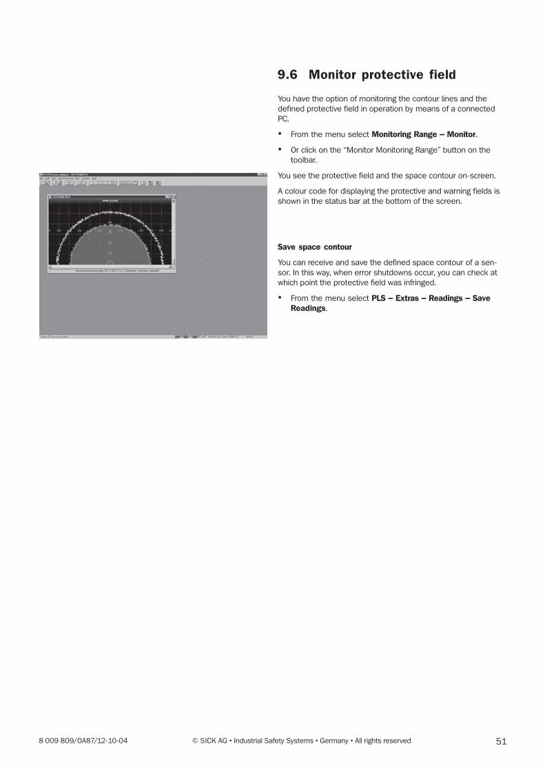
518 009 809/OA87/12-10-04 © SICK AG • Industrial Safety Systems • Germany • All rights reserved
9.6 Monitor protective field
You have the option of monitoring the contour lines and the
defined protective field in operation by means of a connected
PC.
� From the menu select Monitoring Range � Monitor.
� Or click on the “Monitor Monitoring Range” button on the
toolbar.
You see the protective field and the space contour on-screen.
A colour code for displaying the protective and warning fields is
shown in the status bar at the bottom of the screen.
Save space contour
You can receive and save the defined space contour of a sen-
sor. In this way, when error shutdowns occur, you can check at
which point the protective field was infringed.
� From the menu select PLS � Extras � Readings � SaveReadings.
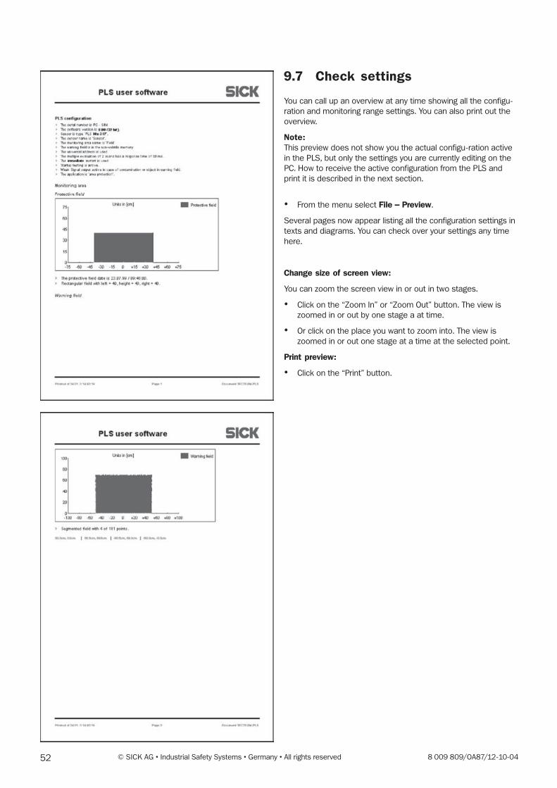
52 © SICK AG • Industrial Safety Systems • Germany • All rights reserved 8 009 809/OA87/12-10-04
9.7 Check settings
You can call up an overview at any time showing all the configu-
ration and monitoring range settings. You can also print out the
overview.
Note:This preview does not show you the actual configu-ration active
in the PLS, but only the settings you are currently editing on the
PC. How to receive the active configuration from the PLS and
print it is described in the next section.
� From the menu select File � Preview.
Several pages now appear listing all the configuration settings in
texts and diagrams. You can check over your settings any time
here.
Change size of screen view:
You can zoom the screen view in or out in two stages.
� Click on the “Zoom In” or “Zoom Out” button. The view is
zoomed in or out by one stage a at time.
� Or click on the place you want to zoom into. The view is
zoomed in or out one stage at a time at the selected point.
Print preview:
� Click on the “Print” button.
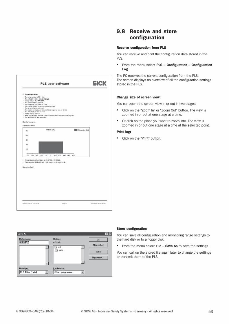
538 009 809/OA87/12-10-04 © SICK AG • Industrial Safety Systems • Germany • All rights reserved
9.8 Receive and storeconfiguration
Receive configuration from PLS
You can receive and print the configuration data stored in the
PLS.
� From the menu select PLS � Configuration � ConfigurationLog.
The PC receives the current configuration from the PLS.
The screen displays an overview of all the configuration settings
stored in the PLS.
Change size of screen view:
You can zoom the screen view in or out in two stages.
� Click on the “Zoom In” or “Zoom Out” button. The view is
zoomed in or out at one stage at a time.
� Or click on the place you want to zoom into. The view is
zoomed in or out one stage at a time at the selected point.
Print log:
� Click on the “Print” button.
Store configuration
You can save all configuration and monitoring range settings to
the hard disk or to a floppy disk.
� From the menu select File � Save As to save the settings.
You can call up the stored file again later to change the settings
or transmit them to the PLS.
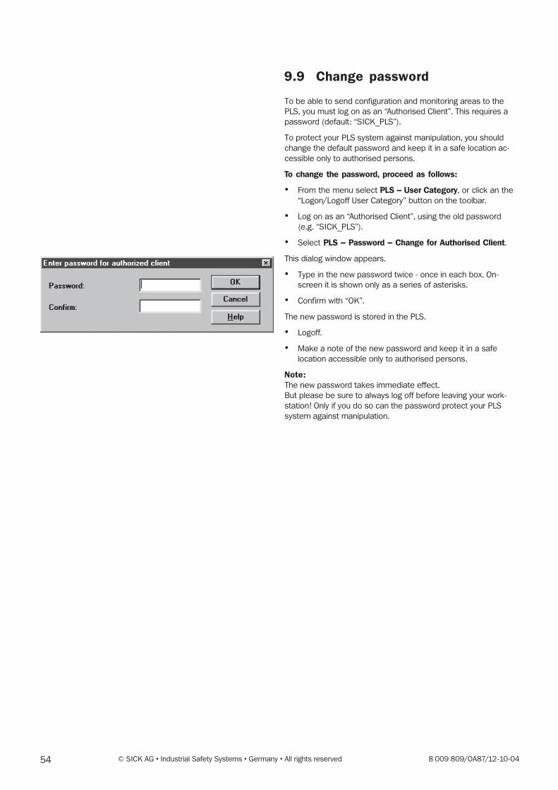
54 © SICK AG • Industrial Safety Systems • Germany • All rights reserved 8 009 809/OA87/12-10-04
9.9 Change password
To be able to send configuration and monitoring areas to the
PLS, you must log on as an “Authorised Client”. This requires a
password (default: “SICK_PLS”).
To protect your PLS system against manipulation, you should
change the default password and keep it in a safe location ac-
cessible only to authorised persons.
To change the password, proceed as follows:
� From the menu select PLS � User Category, or click an the
“Logon/Logoff User Category” button on the toolbar.
� Log on as an “Authorised Client”, using the old password
(e.g. “SICK_PLS”).
� Select PLS � Password � Change for Authorised Client.
This dialog window appears.
� Type in the new password twice - once in each box. On-
screen it is shown only as a series of asterisks.
� Confirm with “OK”.
The new password is stored in the PLS.
� Logoff.
� Make a note of the new password and keep it in a safe
location accessible only to authorised persons.
Note:The new password takes immediate effect.
But please be sure to always log off before leaving your work-
station! Only if you do so can the password protect your PLS
system against manipulation.
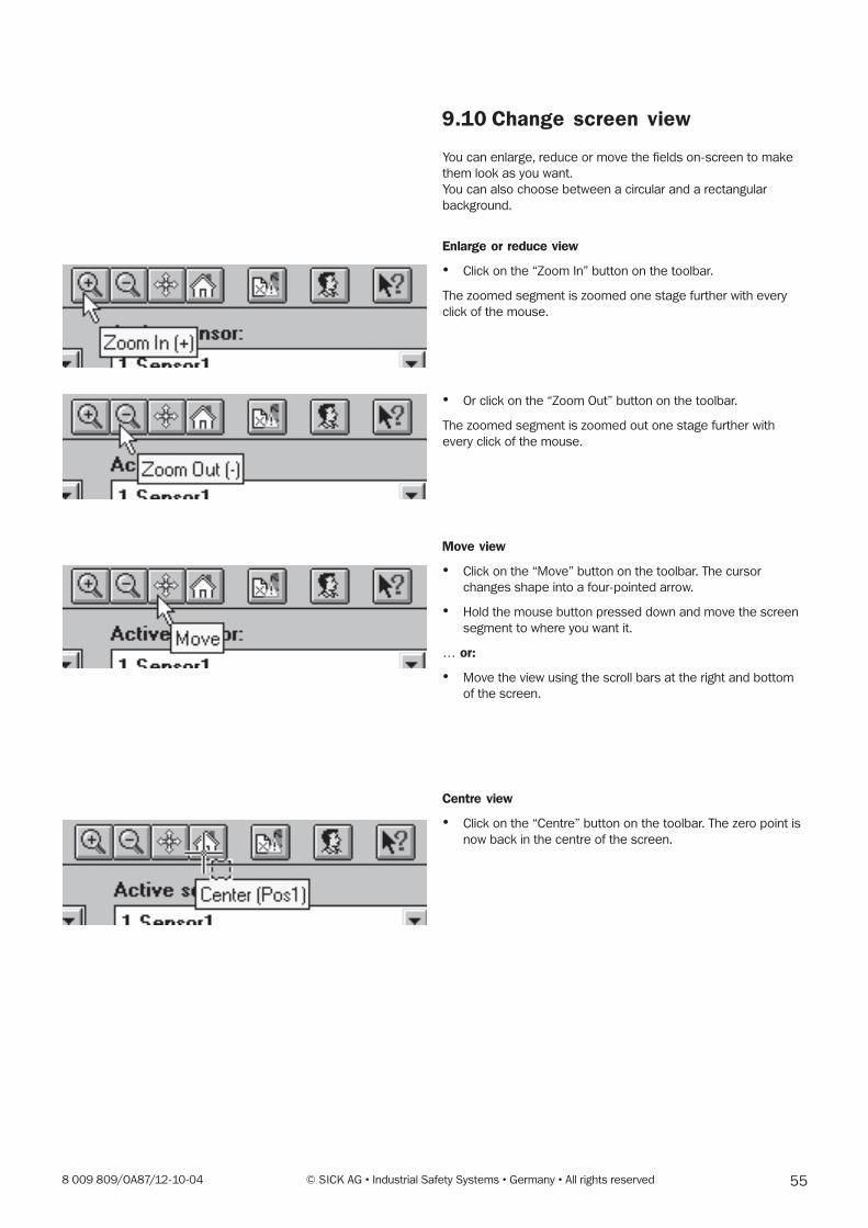
558 009 809/OA87/12-10-04 © SICK AG • Industrial Safety Systems • Germany • All rights reserved
9.10 Change screen view
You can enlarge, reduce or move the fields on-screen to make
them look as you want.
You can also choose between a circular and a rectangular
background.
Enlarge or reduce view
� Click on the “Zoom In” button on the toolbar.
The zoomed segment is zoomed one stage further with every
click of the mouse.
� Or click on the “Zoom Out” button on the toolbar.
The zoomed segment is zoomed out one stage further with
every click of the mouse.
Move view
� Click on the “Move” button on the toolbar. The cursor
changes shape into a four-pointed arrow.
� Hold the mouse button pressed down and move the screen
segment to where you want it.
� or:
� Move the view using the scroll bars at the right and bottom
of the screen.
Centre view
� Click on the “Centre” button on the toolbar. The zero point is
now back in the centre of the screen.
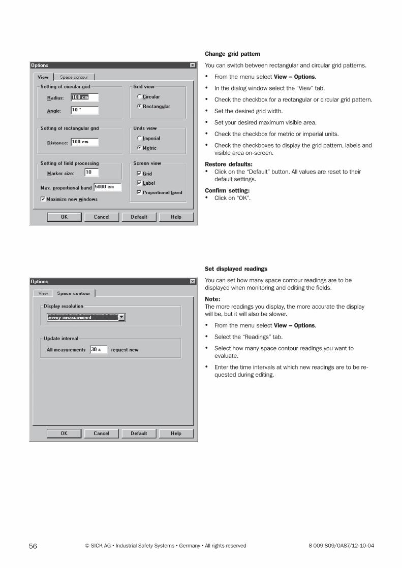
56 © SICK AG • Industrial Safety Systems • Germany • All rights reserved 8 009 809/OA87/12-10-04
Change grid pattern
You can switch between rectangular and circular grid patterns.
� From the menu select View � Options.
� In the dialog window select the “View” tab.
� Check the checkbox for a rectangular or circular grid pattern.
� Set the desired grid width.
� Set your desired maximum visible area.
� Check the checkbox for metric or imperial units.
� Check the checkboxes to display the grid pattern, labels and
visible area on-screen.
Restore defaults:� Click on the “Default” button. All values are reset to their
default settings.
Confirm setting:� Click on “OK”.
Set displayed readings
You can set how many space contour readings are to be
displayed when monitoring and editing the fields.
Note:The more readings you display, the more accurate the display
will be, but it will also be slower.
� From the menu select View � Options.
� Select the “Readings” tab.
� Select how many space contour readings you want to
evaluate.
� Enter the time intervals at which new readings are to be re-
quested during editing.
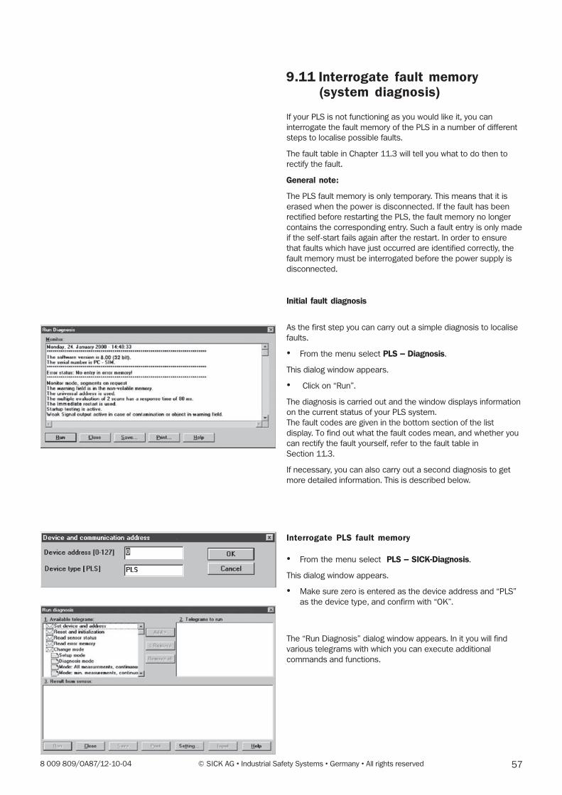
578 009 809/OA87/12-10-04 © SICK AG • Industrial Safety Systems • Germany • All rights reserved
9.11 Interrogate fault memory(system diagnosis)
If your PLS is not functioning as you would like it, you can
interrogate the fault memory of the PLS in a number of different
steps to localise possible faults.
The fault table in Chapter 11.3 will tell you what to do then to
rectify the fault.
General note:
The PLS fault memory is only temporary. This means that it is
erased when the power is disconnected. If the fault has been
rectified before restarting the PLS, the fault memory no longer
contains the corresponding entry. Such a fault entry is only made
if the self-start fails again after the restart. In order to ensure
that faults which have just occurred are identified correctly, the
fault memory must be interrogated before the power supply is
disconnected.
Initial fault diagnosis
As the first step you can carry out a simple diagnosis to localise
faults.
� From the menu select PLS � Diagnosis.
This dialog window appears.
� Click on “Run”.
The diagnosis is carried out and the window displays information
on the current status of your PLS system.
The fault codes are given in the bottom section of the list
display. To find out what the fault codes mean, and whether you
can rectify the fault yourself, refer to the fault table in
Section 11.3.
If necessary, you can also carry out a second diagnosis to get
more detailed information. This is described below.
Interrogate PLS fault memory
� From the menu select PLS � SICK-Diagnosis.
This dialog window appears.
� Make sure zero is entered as the device address and “PLS”
as the device type, and confirm with “OK”.
The “Run Diagnosis” dialog window appears. In it you will find
various telegrams with which you can execute additional
commands and functions.
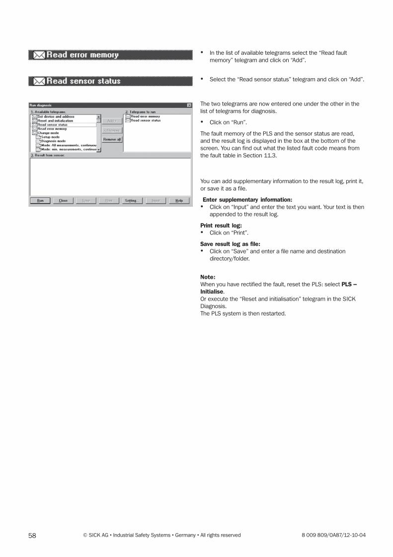
58 © SICK AG • Industrial Safety Systems • Germany • All rights reserved 8 009 809/OA87/12-10-04
� In the list of available telegrams select the “Read fault
memory” telegram and click on “Add”.
� Select the “Read sensor status” telegram and click on “Add”.
The two telegrams are now entered one under the other in the
list of telegrams for diagnosis.
� Click on “Run”.
The fault memory of the PLS and the sensor status are read,
and the result log is displayed in the box at the bottom of the
screen. You can find out what the listed fault code means from
the fault table in Section 11.3.
You can add supplementary information to the result log, print it,
or save it as a file.
Enter supplementary information:� Click on “Input” and enter the text you want. Your text is then
appended to the result log.
Print result log:� Click on “Print”.
Save result log as file:� Click on “Save” and enter a file name and destination
directory/folder.
Note:When you have rectified the fault, reset the PLS: select PLS �Initialise.
Or execute the “Reset and initialisation” telegram in the SICK
Diagnosis.
The PLS system is then restarted.

598 009 809/OA87/12-10-04 © SICK AG • Industrial Safety Systems • Germany • All rights reserved
10 Checks
3. Daily checks of the protective devices by authorised and
instructed persons.
This is how you check your PLS system correctly:
1. Checks must be performed every time the operating
mode is changed.
2. Check the mechanical installation and ensure that lock
screws are tight, and that the PLS is correctly aligned.
3. Check the PLS for visible changes such as damage,
manipulation, etc.
4. Switch on the machine / plant.
5. Observe the PLS LEDs (red, green, yellow).
6. In the event that at least one of the LEDs is not perma-
nently on when the machine / plant is activated, it must
be assumed that there is a fault in the machine / plant.
In this case, the machine must be shut down immedi-
ately and checked by a skilled operator.
7. Intentionally infringe in the protective field while the
machine is operating in order to check the function of the
entire plant. The LEDs must now change colour from
green to red and the hazardous movement must stop
immediately. Repeat this check at various positions in the
danger zone. If a functional deviation is detected, the
machine / plant must be shut down immediately and
checked by a skilled operator.
8. On stationary applications, check whether the danger
zone marked out on the floor corresponds to the shape
of the protective field stored in the PLS, and whether
possible gaps are safeguarded by other protective
measures. In the case of mobile applications, check
whether the vehicle does actually stop moving within the
protective field limits set in the PLS, and displayed on the
notice plates or detailed in the configuration log. If a
functional deviation is detected, the machine / plant
must be shut down immediately and checked by a skilled
operator.
10.1 Check PLS
These checks are necessary to control that the protective
devices are functioning correctly and that they are integrated in
the machine / plant control systems, as well as to detect any
possible alterations or malfunctions.
The following points must be observed to ensure that the
devices are deployed correctly.
The devices must be mounted and electrically connected by
skilled personnel. Skilled personnel are to be understood as
persons who possess sufficient knowledge about the fields of
the power-driven machinery (based on their specialist training
and professional experience). Furthermore, they must be familiar
with the applicable national industrial safety regulations, accident
prevention regulations, guidelines and generally recognised
technical rulings and requirements (e.g. DIN standards, stipula-
tions laid down by the German electricians’ association, techni-
cal regulations of other EU countries) to such an extent, that
they can adjudge the power-driven machinery to be in a condi-
tion where it can be safely operated. Such persons are generally
employees of the manufacturers of non-contact protective
devices, or persons who have been trained by manufacturers of
non-contact protective devices, or who are primarily occupied
with checking non-contact protective devices and who act on
the instructions of non-contact protective device operators.
1. Checking of the protective devices installed on the machine
before commissioning by skilled personnel:
– Checks carried out before commissioning serve the
purpose of confirming that the machinery complies with
national/international regulations, as well as with safety
requirements stipulated by machine or machine operator
guidelines (EU Declaration of Conformity).
– Checking of the effectiveness of the protective devices
installed on the machinery in all the possible operating
modes in accordance with the accompanying check list.
– The operating personnel of the machinery fitted with the
protective devices must be instructed in their use by
skilled personnel employed by the machine operator
before they start to work with the machinery. Instruction
is the responsibility of the machine operator.
You check your PLS system by proceeding in accordance
with the check list printed in the Technical Description.
2. Regular checks of the protective devices by skilled person-
nel:
– Checks in accordance with the nationally applicable
regulations at the stipulated intervals. These checks
serve the purpose of revealing alterations made to, or
manipulation of, the protective devices with regards to
commissioning.
– The checks must always be performed when significant
alterations are made to the machinery or protective
devices, as well as after refitting or maintenance work
necessary following damage to the housing, front screen,
connection cable, etc.
You check your PLS system by proceeding in accordance
with the check list printed in the Technical Description.

60 © SICK AG • Industrial Safety Systems • Germany • All rights reserved 8 009 809/OA87/12-10-04
10.2 Checklist
Check list for the manufacturer / outfitter for installing non-contact protective devices.
Details about the points listed below must be present at least
during initial commissioning – they are, however, dependent on
the respective application, the specifications of which are to be
controlled by the manufacturer / outfitter.
This check list should be stored in a safe place or kept together
with the machine documentation so that it can be used for
reference during repeated checks.
1. Did the safety regulations in accordance with the regula-tions / standards applicable to the machine serve as a basis
for its design? Yes ❏ No ❏
2. Are the guidelines and standards listed in the Declaration of
Conformity? Yes ❏ No ❏
3. Does the protective system comply with the required safety
specifications? Yes ❏ No ❏
4. Is access to the hazardous area / hazard position onlypossible through the protective field of the non-contact
protective devices ? Yes ❏ No ❏
5. Have measures been taken to prevent and monitorunauthorised presence in the hazardous area whensafeguarding hazardous areas / hazard positions (mechani-cal point-of-operation guarding), and have these been
secured against removal? Yes ❏ No ❏
6. Have additional protective measures, which are intended toprevent reaching into, underneath and around the protectivefield, been installed and secured against manipulation?
Yes ❏ No ❏
7. Has the maximum machine shutdown or stopping timebeen measured, and entered and documented (on themachine and / or in the machine documentation)?
Yes ❏ No ❏
8. Are the non-contact protective devices situated at thestipulated safety distance from the next nearest hazard
position? Yes ❏ No ❏
9. Are the non-contact protective devices correctly mountedand, following adjustment, secured against displacement?
Yes ❏ No ❏
10. Are the required safety measures against electrical shock
effective (protection class)? Yes ❏ No ❏
11. Is the command unit for resetting the non-contact protectivedevices or restarting the machine present and correctly
installed? Yes ❏ No ❏
12. Are the non-contact protective device outputs (OSSDs)integrated in accordance with the stipulated controlcategory, and do they comply with the circuit diagrams?
Yes ❏ No ❏
13. Has the protective function been checked in accordancewith the check instructions in this documentation?
Yes ❏ No ❏
14. Are the given protective functions effective at every settingof the operating mode selector switch?
Yes ❏ No ❏
15. Are the switching elements activated by the non-contactprotective devices (e.g. contactors, valves) monitored?
Yes ❏ No ❏
16. Are the non-contact protective devices effective throughoutthe entire dangerous status?
Yes ❏ No ❏
17. Is the corresponding status halted when the non-contactprotective devices are switched on or off, the operatingmodes are changed over, or when switching over to another
protective system? Yes ❏ No ❏
18. Is the notice plate for daily checks clearly visible to the
operator? Yes ❏ No ❏
This check list does not replace the initial commissioning or
regular checks by skilled personnel.

618 009 809/OA87/12-10-04 © SICK AG • Industrial Safety Systems • Germany • All rights reserved
11 Care andMaintenance
The PLS is extensively maintenance-free.
Note:Do not open the sensor. It does not contain any parts youcan repair. In the event of damage occurring to the PLS,contact SICK Service.
Cleaning the front screen
To enable the sensor to function fault-free, you should clean the
front screen as soon as slow rhythmic flashing (once per
second) of the yellow LED accompanied by a steadily lit green
LED signals light contamination.
The PLS will still keep working in this state. Only as the degree of
dirt contamination increases will the yellow LED come on
steadily, the PLS switches off and the red LED lights up (see
“LEDs on the PLS”).
Clean the front screen only with a soft cloth and plastic cleaner.
Never use rough rags or aggressive cleaning agents such as
acetone etc.! Otherwise the front screen may be damaged.
If the front screen is scratched or damaged and needs to be
replaced, you can order a replacement from SICK (see Appendix
under “Accessories”) and replace it yourself.
Replacing the front screen
Notes:The front screen must only be replaced by trained personnel in a
clean environment.
The front screen of the PLS is an optical component which must
not be contaminated with dirt or scratched during replacement.
Do not use silicon to seal the front screen, as the ensuing fumes
could endanger the optical function. Mount the front screen
correctly to ensure that the housing sealing complies with
protection rating IP 65.
Before removing the front screen disconnect the powerconnector to cut power to the unit!
Please carefully follow the assembly instructions for the PLS�Changing the front screen�.
The contamination calibration must be carried out every timethe front screen is replaced!
From the menu select PLS � Extras � Calibration of contami-nation measurement.
Note:The contamination calibration may only be carried outimmediately after replacing the front screen.
The new front screen must not be contaminated with dirt when
the calibration is performed.
11.1 SICK-Service / Hotline
If a fault occurs (e.g. the yellow LED is flashing rapidly, at around
4 times per second), be sure that your first step is always to
carry out the fault diagnosis in the PLS user software. You can
find more details on this in Chapter 9 under “Interrogate fault
memory – System diagnosis”. This SICK diagnosis function will
provide you with detailed information about the fault which has
occurred. You can find out about what the fault code means
from the fault table in Section 11.3, and ascertain whether you
can rectify the fault yourself.
If you are unable to rectify the fault yourself, please contact your
nearest supplier.
Print out the fault report produced by the SICK Diagnosisfunction and have it to hand when you contact SICK Service.
If you need to send in the PLS, please also enclose the fault
report together with the completed Service questionnaire. You
will find a master copy of the Service questionnaire in Section
11.4.
If you are having difficulties or are unsure about how to use your
PLS, please contact our hotline. You can reach it under Tel.
(++49) 7681 / 202-3134 or Fax (++49) 7681 / 202-3130..
SICK also offers an Installation and Commissioning service
package. Our Service department will be able to help you if you
need further assistance.
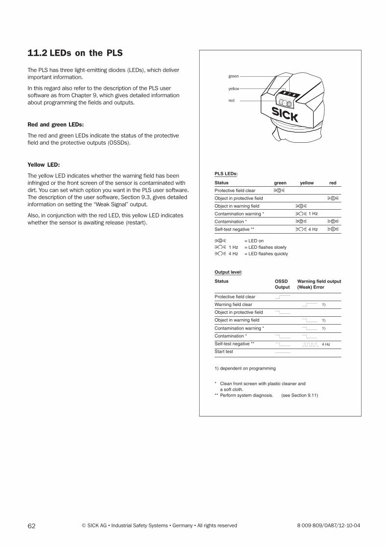
62 © SICK AG • Industrial Safety Systems • Germany • All rights reserved 8 009 809/OA87/12-10-04
11.2 LEDs on the PLS
The PLS has three light-emitting diodes (LEDs), which deliver
important information.
In this regard also refer to the description of the PLS user
software as from Chapter 9, which gives detailed information
about programming the fields and outputs.
Red and green LEDs:
The red and green LEDs indicate the status of the protective
field and the protective outputs (OSSDs).
Yellow LED:
The yellow LED indicates whether the warning field has been
infringed or the front screen of the sensor is contaminated with
dirt. You can set which option you want in the PLS user software.
The description of the user software, Section 9.3, gives detailed
information on setting the “Weak Signal” output.
Also, in conjunction with the red LED, this yellow LED indicates
whether the sensor is awaiting release (restart).
* Clean front screen with plastic cleaner and a soft cloth.
** Perform system diagnosis. (see Section 9.11)
= LED on= LED flashes slowly1 Hz= LED flashes quickly4 Hz
PLS LEDs:
1 Hz
4 Hz
green redyellowStatus
Protective field clear
Object in protective field
Object in warning field
Contamination warning *
Contamination *
Self-test negative **
OSSDOutput
Warning field output(Weak) Error
Status
Protective field clear
Warning field clear
Object in protective field
Object in warning field
Contamination warning *
Contamination *
Self-test negative **
Start test
1) dependent on programming
Output level:
1)
1)
1)
4 Hz
green
yellow
red
638 009 809/OA87/12-10-04 © SICK AG • Industrial Safety Systems • Germany • All rights reserved
11.3 PLS Fault table
For safety reasons your PLS continuously performs self-test
routines to guarantee fault-free functioning of the unit in case of
danger. If one of these tests fails when the system is starting up
or during operation, the PLS automatically shuts down the
dangerous machine or plant as a safety precaution.
This table enables you to find out whether the SICK diagnosis
fault codes mean, and whether you can rectify the fault yourself.
How to execute the SICK diagnosis is described in Section 9.11.
Note:If you get a fault code which you cannot find in the table, please
contact SICK Service.
Error code: Cause / What you can do about it:
2�16 Internal error:Cut the power to the PLS for at least 3 seconds. If the problem persists, contact the SICK Hotline.
17�20 Dirt contamination of the front screen:Clean the front screen or replace it. The contamination calibration must be performed every time
the front screen is replaced!
24 Mutual interference between several PLS units:Eliminate the interference by changing the PLS mounting configuration. Follow the mounting
instructions in Chapter 7.
Motor speed incorrect:Operating at low temperatures. Observe the specifications of the unit (see Technical data).
27 External circuitry of OSSD 1 faulty:Check the wiring of the external circuitry. Test for short-circuit in the shutdown path to 0 volts, to
24 volts and to the second shutdown path. Make sure the resistive and capacitive load on the
shutdown path complies with the unit specifications. Also test the connectors and the crimping of
the cabling.
Undervoltage in power supply to unit:Make sure the power supply to the unit complies with the specification (see Technical data).
Measure the voltage directly on the PLS to take account of any voltage drop resulting from long
supply lines.
28 External circuitry of OSSD 2 faulty:See error code 27
Undervoltage in power supply to unit:See error code 27
29 Motor speed incorrect:Operating at low temperatures. Observe the specifications of the unit (see Technical data).
31 Sensor dazzled while measuring:Check whether the PLS is being dazzled by an external light source, e.g. headlights, infrared light
sources, sun etc. Slightly altering the location of the PLS may be sufficient to solve the problem
(to do this observe the mounting instructions described in Chapter 5). If you are using the PLS on
a driverless transport system, check whether the application variant “Vehicle protection” has been
selected.
64 © SICK AG • Industrial Safety Systems • Germany • All rights reserved 8 009 809/OA87/12-10-04
Error code: Cause / What you can do about it:
32 Object detected in the protective field:Check the ambient conditions.
Adjust the PLS configuration to the ambient conditions.
33 Object detected in the protective field:Check the ambient conditions.
Adjust the PLS configuration to the ambient conditions.
41 Shutdown paths are not interacting correctly:See error codes 27 and 28, for undervoltage in the unit power supply see error code 27.
42 Sensor receiving no data over 90° of its measuring range:To ensure fault-free functioning of the sensor, make sure it is always receiving readings within a
range of 90°, and is freely adjustable within the scanning area. In area protection this is normally
always the case, so the PLS signals the fault after three seconds. In vehicle protection a condition
of this kind may occur briefly while the vehicle is moving across the hall, so the unit only signals
this fault after two hours.

658 009 809/OA87/12-10-04 © SICK AG • Industrial Safety Systems • Germany • All rights reserved
11.4 Service questionnaire
On the following page you will find our Service questionnaire.
This is designed to record all relevant data relating to any PLS
laser scanner sent in to us.
Based on the information you give, we are able to take all
necessary measures straight away to ensure your scanner is re-
turned to you as soon as possible.
Please return the completed questionnaire with the scanner.

66 © SICK AG • Industrial Safety Systems • Germany • All rights reserved 8 009 809/OA87/12-10-04
Sick AG, Seb.-Kneipp-Straße 1, D-79183 Waldkirch, Tel.: (++49) 7681 / 202 - 3134, Fax: - 3130
PLS - Service Questionnaire
By completing the questionnaire below you will help us by carrying out fault diagnosis. As soon as we have the following
details, we will get back to you as quickly as possible. This makes efficient handling of queries possible.
Company _______________________________________________________________
Contact _________________________ Sick contact _________________________
Adress _______________________________________________________________
Phone _________________________ Fax: _________________________________
Hardware as per rating plate: PLS model: PLS _ _ _ - _ _ _
Order number: 1 0 _ _ _ _ _
Device number: _ _ _ _ _ _ _ _
Software: PLS user software version: 0_ . _ _
– Select “About User Software” from the “Help” menu.
Sensor status: Please enclose printout:
– Log on to the user software as an “Authorised Client”.
– Select “SICK diagnosis” from the “Sensor” menu.
– Select, add, run and save the telegrams “Read sensor status”
and “Read fault memory”.
Application: Area protection ❏ Mobile application ❏
Problem: _______________________________________________________________
_______________________________________________________________
_______________________________________________________________
If the yellow LED is flashing rapidly (4 times per second):
– Is the voltage to the PLS power connector in the permissible range?
no ❏ yes ❏ Please enter the mean voltage: ______V
If the red LED is flashing rapidly (approx. 2 times per second):
– Does the 24 V power pack of the PLS have a load capacity of at least 1.5 A? no ❏ yes ❏
If the red LED is active:
– Where is the protective field being infringed? Interior ❏ Edges ❏
– Please describe the application and any critical ambient conditions:
_______________________________________________________________________________
_______________________________________________________________________________
_______________________________ Sketch of application on back: yes ❏ no ❏
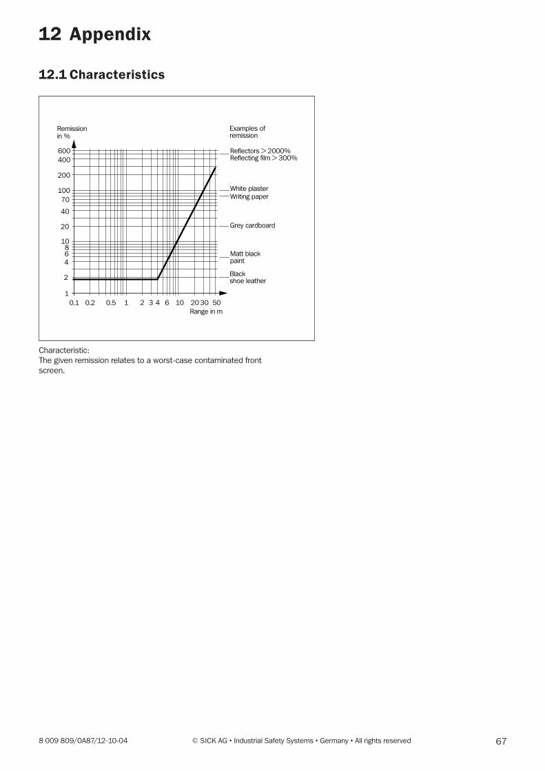
678 009 809/OA87/12-10-04 © SICK AG • Industrial Safety Systems • Germany • All rights reserved
12 Appendix
Characteristic:
The given remission relates to a worst-case contaminated front
screen.
12.1 Characteristics
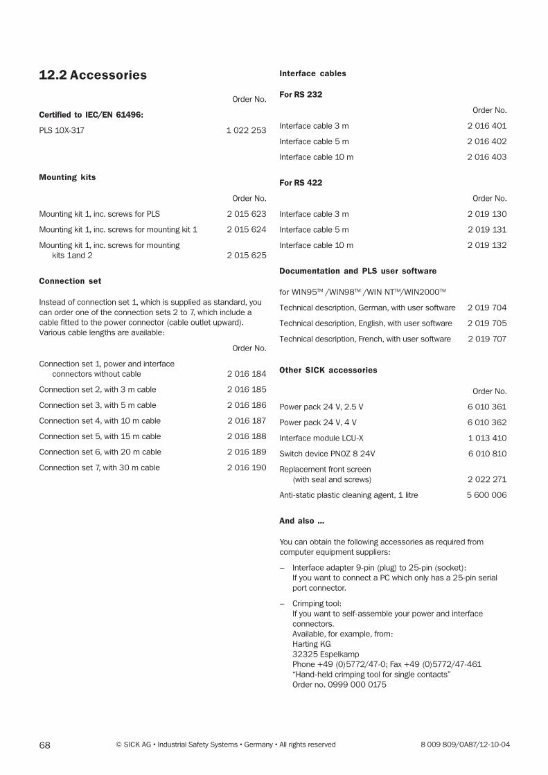
68 © SICK AG • Industrial Safety Systems • Germany • All rights reserved 8 009 809/OA87/12-10-04
12.2 Accessories
Order No.
Certified to IEC/EN 61496:
PLS 10X-317 1 022 253
Mounting kits
Order No.
Mounting kit 1, inc. screws for PLS 2 015 623
Mounting kit 1, inc. screws for mounting kit 1 2 015 624
Mounting kit 1, inc. screws for mounting
kits 1and 2 2 015 625
Connection set
Instead of connection set 1, which is supplied as standard, you
can order one of the connection sets 2 to 7, which include a
cable fitted to the power connector (cable outlet upward).
Various cable lengths are available:
Order No.
Connection set 1, power and interface
connectors without cable 2 016 184
Connection set 2, with 3 m cable 2 016 185
Connection set 3, with 5 m cable 2 016 186
Connection set 4, with 10 m cable 2 016 187
Connection set 5, with 15 m cable 2 016 188
Connection set 6, with 20 m cable 2 016 189
Connection set 7, with 30 m cable 2 016 190
Interface cables
For RS 232
Order No.
Interface cable 3 m 2 016 401
Interface cable 5 m 2 016 402
Interface cable 10 m 2 016 403
For RS 422
Order No.
Interface cable 3 m 2 019 130
Interface cable 5 m 2 019 131
Interface cable 10 m 2 019 132
Documentation and PLS user software
for WIN95TM /WIN98TM /WIN NTTM/WIN2000TM
Technical description, German, with user software 2 019 704
Technical description, English, with user software 2 019 705
Technical description, French, with user software 2 019 707
Other SICK accessories
Order No.
Power pack 24 V, 2.5 V 6 010 361
Power pack 24 V, 4 V 6 010 362
Interface module LCU-X 1 013 410
Switch device PNOZ 8 24V 6 010 810
Replacement front screen
(with seal and screws) 2 022 271
Anti-static plastic cleaning agent, 1 litre 5 600 006
And also ...
You can obtain the following accessories as required from
computer equipment suppliers:
– Interface adapter 9-pin (plug) to 25-pin (socket):
If you want to connect a PC which only has a 25-pin serial
port connector.
– Crimping tool:
If you want to self-assemble your power and interface
connectors.
Available, for example, from:
Harting KG
32325 Espelkamp
Phone +49 (0)5772/47-0; Fax +49 (0)5772/47-461
“Hand-held crimping tool for single contacts”
Order no. 0999 000 0175
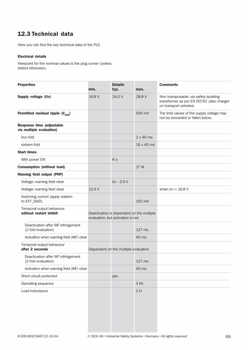
698 009 809/OA87/12-10-04 © SICK AG • Industrial Safety Systems • Germany • All rights reserved
12.3 Technical data
Here you can find the key technical data of the PLS.
Electrical details
Viewpoint for the nominal values is the plug corner (unless
stated otherwise).
Properties Details Commentsmin. typ. max.
Supply voltage (Uv) 16.8 V 24.0 V 28.8 V Non-transposable, via safety isolating
transformer as per EN 60742 (also charger
on transport vehicles)
Permitted residual ripple (VRMS
) 500 mV The limit values of the supply voltage may
not be exceeded or fallen below.
Response time (adjustablevia multiple evaluation)
two-fold 2 x 40 ms
sixteen-fold 16 x 40 ms
Start times
With power ON 6 s
Consumption (without load) 17 W
Warning field output (PNP)
Voltage: warning field clear Uv - 2.5 V
Voltage: warning field clear 13.4 V when Uv = 16.8 V
Switching current (apply relation
to EXT_GND) 100 mA
Temporal output behaviour
without restart inhibit Deactivation is dependent on the multiple
evaluation, but activation is not
Deactivation after WF infringement
(2-fold evaluation) 127 ms
Activation when warning field (WF) clear 40 ms
Temporal output behaviour
after 2 seconds Dependent on the multiple evaluation
Deactivation after WF infringement
(2-fold evaluation) 127 ms
Activation when warning field (WF) clear 40 ms
Short-circuit-protected yes
Operating sequence 3 Hz
Load inductance 2 H
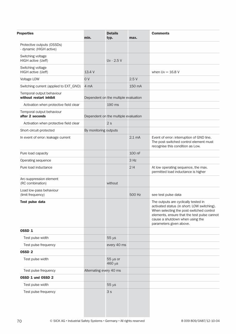
70 © SICK AG • Industrial Safety Systems • Germany • All rights reserved 8 009 809/OA87/12-10-04
Properties Details Commentsmin. typ. max.
Protective outputs (OSSDs)
- dynamic (HIGH active)
Switching voltage
HIGH active (Ueff) Uv - 2.5 V
Switching voltage
HIGH active (Ueff) 13.4 V when Uv = 16.8 V
Voltage LOW 0 V 2.5 V
Switching current (applied to EXT_GND) 4 mA 150 mA
Temporal output behaviour
without restart inhibit Dependent on the multiple evaluation
Activation when protective field clear 190 ms
Temporal output behaviour
after 2 seconds Dependent on the multiple evaluation
Activation when protective field clear 2 s
Short-circuit-protected By monitoring outputs
In event of error: leakage current 2.1 mA Event of error: interruption of GND line.
The post-switched control element must
recognise this condition as Low.
Pure load capacity 100 nF
Operating sequence 3 Hz
Pure load inductance 2 H At low operating sequence, the max.
permitted load inductance is higher
Arc-suppression element
(RC combination) without
Load low-pass behaviour
(limit frequency) 500 Hz see test pulse data
Test pulse data The outputs are cyclically tested in
activated status (in short: LOW switching).
When selecting the post-switched control
elements, ensure that the test pulse cannot
cause a shutdown when using the
parameters given above.
OSSD 1
Test pulse width 55 µs
Test pulse frequency every 40 ms
OSSD 2
Test pulse width 55 µs or
460 µs
Test pulse frequency Alternating every 40 ms
OSSD 1 und OSSD 2
Test pulse width 55 µs
Test pulse frequency 3 s
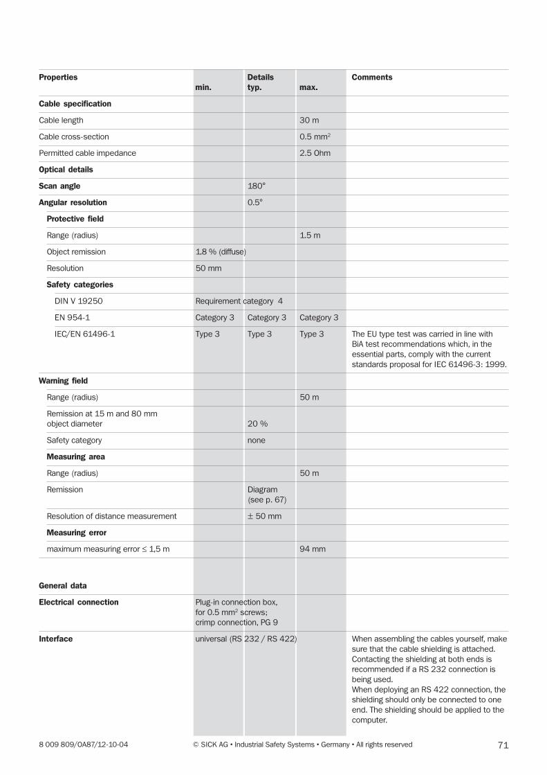
718 009 809/OA87/12-10-04 © SICK AG • Industrial Safety Systems • Germany • All rights reserved
Properties Details Commentsmin. typ. max.
Cable specification
Cable length 30 m
Cable cross-section 0.5 mm2
Permitted cable impedance 2.5 Ohm
Optical details
Scan angle 180°
Angular resolution 0.5°
Protective field
Range (radius) 1.5 m
Object remission 1.8 % (diffuse)
Resolution 50 mm
Safety categories
DIN V 19250 Requirement category 4
EN 954-1 Category 3 Category 3 Category 3
IEC/EN 61496-1 Type 3 Type 3 Type 3 The EU type test was carried in line with
BiA test recommendations which, in the
essential parts, comply with the current
standards proposal for IEC 61496-3: 1999.
Warning field
Range (radius) 50 m
Remission at 15 m and 80 mm
object diameter 20 %
Safety category none
Measuring area
Range (radius) 50 m
Remission Diagram
(see p. 67)
Resolution of distance measurement ± 50 mm
Measuring error
maximum measuring error ≤ 1,5 m 94 mm
General data
Electrical connection Plug-in connection box,
for 0.5 mm2 screws;
crimp connection, PG 9
Interface universal (RS 232 / RS 422) When assembling the cables yourself, make
sure that the cable shielding is attached.
Contacting the shielding at both ends is
recommended if a RS 232 connection is
being used.
When deploying an RS 422 connection, the
shielding should only be connected to one
end. The shielding should be applied to the
computer.
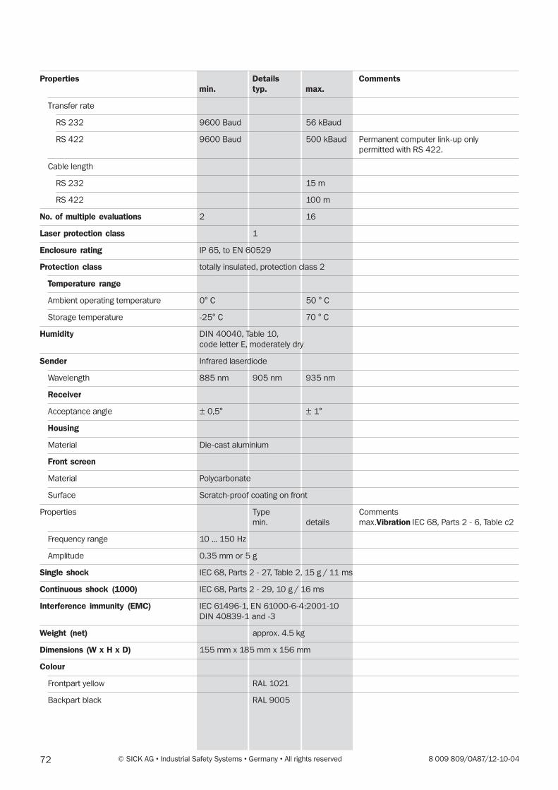
72 © SICK AG • Industrial Safety Systems • Germany • All rights reserved 8 009 809/OA87/12-10-04
Properties Details Commentsmin. typ. max.
Transfer rate
RS 232 9600 Baud 56 kBaud
RS 422 9600 Baud 500 kBaud Permanent computer link-up only
permitted with RS 422.
Cable length
RS 232 15 m
RS 422 100 m
No. of multiple evaluations 2 16
Laser protection class 1
Enclosure rating IP 65, to EN 60529
Protection class totally insulated, protection class 2
Temperature range
Ambient operating temperature 0° C 50 ° C
Storage temperature -25° C 70 ° C
Humidity DIN 40040, Table 10,
code letter E, moderately dry
Sender Infrared laserdiode
Wavelength 885 nm 905 nm 935 nm
Receiver
Acceptance angle ± 0,5° ± 1°
Housing
Material Die-cast aluminium
Front screen
Material Polycarbonate
Surface Scratch-proof coating on front
Properties Type Comments
min. details max.Vibration IEC 68, Parts 2 - 6, Table c2
Frequency range 10 ... 150 Hz
Amplitude 0.35 mm or 5 g
Single shock IEC 68, Parts 2 - 27, Table 2, 15 g / 11 ms
Continuous shock (1000) IEC 68, Parts 2 - 29, 10 g / 16 ms
Interference immunity (EMC) IEC 61496-1, EN 61000-6-4:2001-10
DIN 40839-1 and -3
Weight (net) approx. 4.5 kg
Dimensions (W x H x D) 155 mm x 185 mm x 156 mm
Colour
Frontpart yellow RAL 1021
Backpart black RAL 9005
738 009 809/OA87/12-10-04 © SICK AG • Industrial Safety Systems • Germany • All rights reserved
12.4 Standards and regulations
The following lists the key standards and regulations applicable to
the use of optoelectronic safety devices in Europe and in the
Federal Republic of Germany. Depending on the field of applica-
tion, additional regulations may be of importance for you. You can
get information on other device-specific standards from local
regulatory authorities, or from professional bodies. If the machine
or vehicle is operated in a country not belonging to the European
Union, we recommend contacting the plant operators and the
local authorities.
Regarding the use and installation of safety devices:
Machine Directive 89 / 392 EEC
Safety of machines – Basic terms, general design guidelines
(EN 292)
Safety of integrated manufacturing systems (DIN EN 1921)
Safety of machines – Electrical equipment on machines –
Part 1: General requirements (EN 60204)
Safety of machines – Safety distances to prevent reaching haz-
ardous areas with upper limbs (EN 294)
Safety requirements for robots (EN 775)
Safety rules for non-contact safety devices on power-driven
machinery (ZH 1 / 597)
Safety of machines – Arrangement of safety devices with regard
to approach speed of body parts (EN 999)
Safety of machines – Risk assessment (EN 1050)
Regarding construction and equipping of safety devices:
Safety of machines – Non-contact safety devices – Part 1: Gen-
eral requirements (EN 50100-1 and -2 / DIN VDE 0113,
Part 201)
Basic safety observations for instrumentation and control safety
devices (DIN V 19250)
Safety of machines – Electrical equipment on machines – Part L:
General requirements (EN 60204)
Safety of machines – Safety-related components of controls –
Part 1: General design guidelines (EN 954)
On these subjects please also order our brochure “Safe machines
with optoelectronic safety devices”.
The recommendations regarding mounting apply.
74 © SICK AG • Industrial Safety Systems • Germany • All rights reserved 8 009 809/OA87/12-10-04
13 Glossary
DTS
Driverless Transport System (industrial conveyors).
Fault memory
A code describing the occurring fault is written to the fault
memory. This error code can be read-out by the SICK diagnosis
system to provide initial fault analysis.
Measurement zone
The field of vision of the PLS is its measurement zone. It is
heavily dependent on the remission of the object struck, but
without special measures also extends to around 15 metres.
When using heavily reflective materials the maximum range of
the 50 metres is also achievable.
With the PLS the distance to objects can also be measured in
order to display them on the PC (via the computer interface) or
to carry out any other evaluations on the computer.
OSSD
The OSSD outut is the switching output of the PLS. This is semi-
conductor based, and its fault-free functioning is tested periodi-
cally. The PLS has two parallel-working OSSD outputs, which for
safety reasons must be evaluated on two channels.
Protective field
In the “close-up zone” (radius 1.5 metres) the PLS offers a
sensor field with fail-safe accident prevention functions in
accordance with category 4 of DIN 19250 – for area protection
but also as a (non-tactile) bumper replacement.
Remission
The remission describes the diffuse reflectance of surfaces.
Restart inhibit
A device for preventing a plant from being automatically re-
started after activation of the sensor function during a hazard-
ous part of the machine cycle, after altering the operating or
activation mode, or after changing the start control device on
the machinery.
Segmented field
Protective fields are handled in segmented form; that is to say, a
protective field consists of triangular areas touching each other
at the edges of the field. You can freely select the number of
segments on which a field is based between 90, 180 and 360.
Sensor status
The sensor status characterises the overall state of the system
in detail. The data it contains is required to analyse the system.
Start-up testing
When the power has been connected the sensor releases the
plant only after the protective field has been infringed intention-
ally once.
Verification of the protective field
To ensure the registered contour really matches the area being
protected, especially when teaching-in a protective field, it is
necessary to “show” the sensor the desired field a second time
as confirmation. This is done in the so-called verification process
by slowly running a target board over the contour along the
inside of the protective field (toward the sensor), but no more
than 70 cm from the edge of the protective field. The process
can be tracked on-screen by following the change in beam
colour from red to green.
Warning field
The warning field is a sensor field with a radius of up to
50 metres. It can be used to monitor larger areas and to trip
simple switching functions (e.g. warning functions) or to switch
a driverless transport system to slow running.


Contact:
A u s t r a l i aPhone +61 3 9497 4100
1800 33 48 02 – tollfreeE-Mail [email protected]
B e l g i u m / L u x e m b o u r gPhone +32 (0)2 466 55 66E-Mail [email protected]
B r a s i lPhone +55 11 5091-4900E-Mail [email protected]
C e s k á R e p u b l i k aPhone +420 2 57 91 18 50E-Mail [email protected]
C h i n aPhone +852-2763 6966E-Mail [email protected]
D a n m a r kPhone +45 45 82 64 00E-Mail [email protected]
D e u t s c h l a n dPhone +49 (0)2 11 53 01-260E-Mail [email protected]
E s p a ñ aPhone +34 93 480 31 00E-Mail [email protected]
F r a n c ePhone +33 1 64 62 35 00E-Mail [email protected]
G r e a t B r i t a i nPhone +44 (0)1727 831121E-Mail [email protected]
I t a l i aPhone +39 02 27 40 93 19E-Mail [email protected]
J a p a nPhone +81 (0)3 3358 1341E-Mail [email protected]
K o r e aPhone +82-2 786 6321/4E-Mail [email protected]
N e d e r l a n d sPhone +31 (0)30 229 25 44E-Mail [email protected]
N o r g ePhone +47 67 81 50 00E-Mail [email protected]
Ö s t e r r e i c hPhone +43 (0)22 36 62 28 8-0E-Mail [email protected]
P o l s k aPhone +48 22 837 40 50E-Mail [email protected]
S c h w e i zPhone +41 41 619 29 39E-Mail [email protected]
S i n g a p o r ePhone +65 6744 3732E-Mail [email protected]
S u o m iPhone +358-9-25 15 800E-Mail [email protected]
S v e r i g ePhone +46 8 680 64 50E-Mail [email protected]
T ü r k i y ePhone +90 216 388 95 90 pbxE-Mail [email protected]
T a i w a nPhone +886 2 2365-6292E-Mail [email protected]
U S A / C a n a d a / M é x i c oPhone +1(952) 941-6780
1 800-325-7425 – tollfreeE-Mail [email protected]
More representatives and agencies
in all major industrial nations at
www.sick.com
SICK AG • Industrial Safety Systems • Waldkirch • Germany • www.sick.com
8 0
09
80
9/0
A8
7/1
2-1
0-0
4 •
GO
/XX
•
Printe
d in G
erm
any
(xx-
xx) •
Subje
ct
to c
hange w
ithout
prior
notice •
The s
pecifie
d p
roduct
featu
res a
nd t
echnic
al data
do n
ot
repre
sent
any
guara
nte
e •
02
A4
2
c iin
t17