Embed Size (px)
Citation preview
1
Providing Wireless Coverage to High-rise BuildingsUsing UAVs
Hazim Shakhatreh1, Abdallah Khreishah1, and Bo Ji2
1Department of Electrical and Computer Engineering, New Jersey Institute of Technology2Department of Computer and Information Sciences, Temple University
Abstract—Unmanned aerial vehicles (UAVs) can be used asaerial wireless base stations when cellular networks go down.Prior studies on UAV-based wireless coverage typically consideran Air-to-Ground path loss model, which assumes that the usersare outdoor and they are located on a 2D plane. In this paper,we propose using a single UAV to provide wireless coverage forindoor users inside a high-rise building under disaster situations(such as earthquakes or floods), when cellular networks are down.First, we present a realistic Outdoor-Indoor path loss model anddescribe the tradeoff introduced by this model. Then, we studythe problem of efficient UAV placement, where the objective is tominimize the total transmit power required to cover the entirehigh-rise building. The formulated problem is non-convex and isgenerally difficult to solve. To that end, we consider two casesof practical interest and provide the efficient solutions to theformulated problem under these cases. In the first case, we aimto find the minimum transmit power such that an indoor userwith the maximum path loss can be covered. In the second case,we assume that the locations of indoor users are symmetric acrossthe dimensions of each floor.
Index Terms—Unmanned aerial vehicles, Outdoor-to-Indoorpath loss model.
I. INTRODUCTION
UAVs can be used to provide wireless coverage duringemergency cases where each UAV serves as an aerial wirelessbase station when the cellular network goes down [1]. Theycan also be used to supplement the ground base station inorder to provide better coverage and higher data rates for theusers [2].
In order to use a UAV as an aerial wireless base station, theauthors in [3] presented an Air-to-Ground path loss model thathelped the academic researchers to formulate many importantproblems. The authors of [4]–[8] utilized this model to studythe problem of UAV placement, where the objective is tominimize the number of UAVs for covering a given area.The authors of [4] described the tradeoff in this model. Ata low altitude, the path loss between the UAV and the grounduser decreases, while the probability of line of sight links alsodecreases. On the other hand, at a high altitude line of sightconnections exist with a high probability, while the path lossincreases. However, it is assumed that all users are outdoor andthe location of each user can be represented by an outdoor 2Dpoint. These assumptions limit the applicability of this modelwhen one needs to consider indoor users.
Providing good wireless coverage for indoor users is veryimportant. According to Ericsson report [9], 90% of the time
people are indoor and 80% of the mobile Internet access trafficalso happens indoors [10], [11]. To guarantee the wirelesscoverage, the service providers are faced with several keychallenges, including providing service to a large number ofindoor users and the ping pong effect due to interference fromnear-by macro cells [12]–[14]. In this paper, we propose usinga single UAV to provide wireless coverage for users inside ahigh-rise building during emergency cases, when the cellularnetwork service is not available.
To the best of our knowledge, this is the first work thatproposes using a UAV to provide wireless coverage for indoorusers. We summarize our main contributions as follows. First,we assume an Outdoor-Indoor path loss model [15], certifiedby ITU, and show the tradeoff introduced by this model.Second, we formulate the problem of efficient UAV placement,where the objective is to minimize the total transmit powerrequired to cover the entire high-rise building. Third, since theformulated problem is non-convex and is generally difficult tosolve, we consider two cases of practical interest and providethe efficient solutions to the formulated problem under thesecases. In the first case, we aim to find the minimum transmitpower such that an indoor user with the maximum path losscan be covered. In the second case, we assume that thelocations of indoor users are symmetric across the dimensionsof each floor, and propose a gradient descent algorithm forfinding the efficient location of the UAV.
The rest of this paper is organized as follows. In Section II,we describe the system model and a path loss model suitablefor studying indoor wireless coverage. In Section III, weformulate the problem of UAV placement with an objective ofminimizing the transmit power for covering the entire building.In Section IV, we describe the tradeoff introduced by thepath loss model and show how to find the efficient locationof the UAV such that the total transmit power is minimizedin two scenarios of practical interest. Finally, we present ournumerical results in Section V and make concluding remarksin Section VI.
II. SYSTEM MODEL
A. System Settings
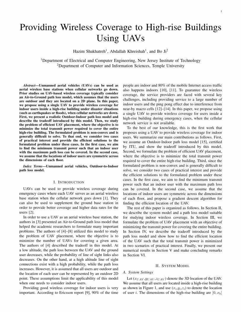
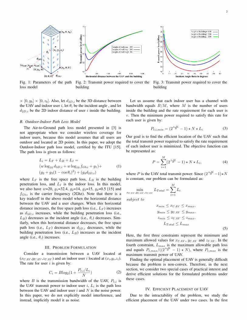
Let (xUAV ,yUAV ,zUAV ) denote the 3D location of the UAV.We assume that all users are located inside a high-rise buildingas shown in Figure 1, and use (xi,yi,zi) to denote the locationof user i. The dimensions of the high-rise building are [0, xb]
2
Fig. 1: Parameters of the pathloss model
Fig. 2: Transmit power required to cover thebuilding
Fig. 3: Transmit power required to cover thebuilding
× [0, yb] × [0, zb]. Also, let d3D,i be the 3D distance betweenthe UAV and indoor user i, let θi be the incident angle , and letd2D,i be the 2D indoor distance of user i inside the building.
B. Outdoor-Indoor Path Loss Model
The Air-to-Ground path loss model presented in [3] isnot appropriate when we consider wireless coverage forindoor users, because this model assumes that all users areoutdoor and located at 2D points. In this paper, we adopt theOutdoor-Indoor path loss model, certified by the ITU [15].The path loss is given as follows:
Li = LF + LB + LI =
(w log10 d3D,i + w log10 fGhz + g1)+
(g2 + g3(1− cos θi)2) + (g4d2D,i)
(1)
where LF is the free space path loss, LB is the buildingpenetration loss, and LI is the indoor loss. In this model,we also have w=20, g1=32.4, g2=14, g3=15, g4=0.5 [15] andfGhz is the carrier frequency (2Ghz). Note that there is akey tradeoff in the above model when the horizontal distancebetween the UAV and a user changes. When this horizontaldistance increases, the free space path loss (i.e., LF ) increasesas d3D,i increases, while the building penetration loss (i.e.,LB) decreases as the incident angle (i.e., θi) decreases. Sim-ilarly, when this horizontal distance decreases, the free spacepath loss (i.e., LF ) decreases as d3D,i decreases, while thebuilding penetration loss (i.e., LB) increases as the incidentangle (i.e., θi) increases.
III. PROBLEM FORMULATION
Consider a transmission between a UAV located at(xUAV ,yUAV ,zUAV ) and an indoor user i located at (xi,yi,zi).The rate for user i is given by:
Ci = Blog2(1 +Pt,i/LiN
) (2)
where B is the transmission bandwidth of the UAV, Pt,i isthe UAV transmit power to indoor user i, Li is the path lossbetween the UAV and indoor user i and N is the noise power.In this paper, we do not explicitly model interference, andinstead, implicitly model it as noise.
Let us assume that each indoor user has a channel withbandwidth equals B/M , where M is the number of usersinside the building and the rate requirement for each user isv. Then the minimum power required to satisfy this rate foreach user is given by:
Pt,i,min = (2v.MB − 1) ? N ? Li (3)
Our goal is to find the efficient location of the UAV such thatthe total transmit power required to satisfy the rate requirementof each indoor user is minimized. The objective function canbe represented as:
P =
M∑i=1
(2v.MB − 1) ? N ? Li, (4)
where P is the UAV total transmit power. Since (2v.MB −1)?N
is constant, our problem can be formulated as:
minxUAV ,yUAV ,zUAV
LTotal =
M∑i=1
Li
subject to
xmin ≤ xUAV ≤ xmax,ymin ≤ yUAV ≤ ymax,zmin ≤ zUAV ≤ zmax,
LTotal ≤ Lmax(5)
Here, the first three constraints represent the minimum andmaximum allowed values for xUAV , yUAV and zUAV . In thefourth constraint, Lmax is the maximum allowable path lossand equals Pt,max/((2
v.MB − 1) ? N), where Pt,max is the
maximum transmit power of UAV.Finding the optimal placement of UAV is generally difficult
because the problem is non-convex. Therefore, in the nextsection, we consider two special cases of practical interest andderive efficient solutions for the formulated problems underthese cases.
IV. EFFICIENT PLACEMENT OF UAV
Due to the intractability of the problem, we study theefficient placement of the UAV under two cases. In the first
3
case, we find the minimum transmit power required to coverthe building based on the location that has the maximum pathloss inside the building. In the second case, we assume that thelocations of indoor users are symmetric across the dimensionsof each floor, and propose a gradient descent algorithm forfinding the efficient location of the UAV.
A. Case One: The worst location in building
In this case, we find the minimum transmit power requiredto cover the building based on the location that has themaximum path loss inside the building. The location that hasthe maximum path loss in the building is the location thathas maximum d3D,i, maximum θi, and maximum d2D,i. Thelocations that have the maximum path loss are located at thecorners of the highest and lowest floors at points (xb, 0, 0),(xb, yb, 0), (xb, 0, zb) and (xb, yb, zb) (see Figure 1). Since thelocations that have the maximum path loss inside the buildingare the corners of the highest and lowest floors, we placethe UAV at the middle of the building (yUAV = 0.5yb andzUAV =0.5zb). Then, given the Outdoor-to-Indoor path lossmodel, we need to find the optimal horizontal point xUAVfor the UAV such that the total transmit power required tocover the building is minimized.
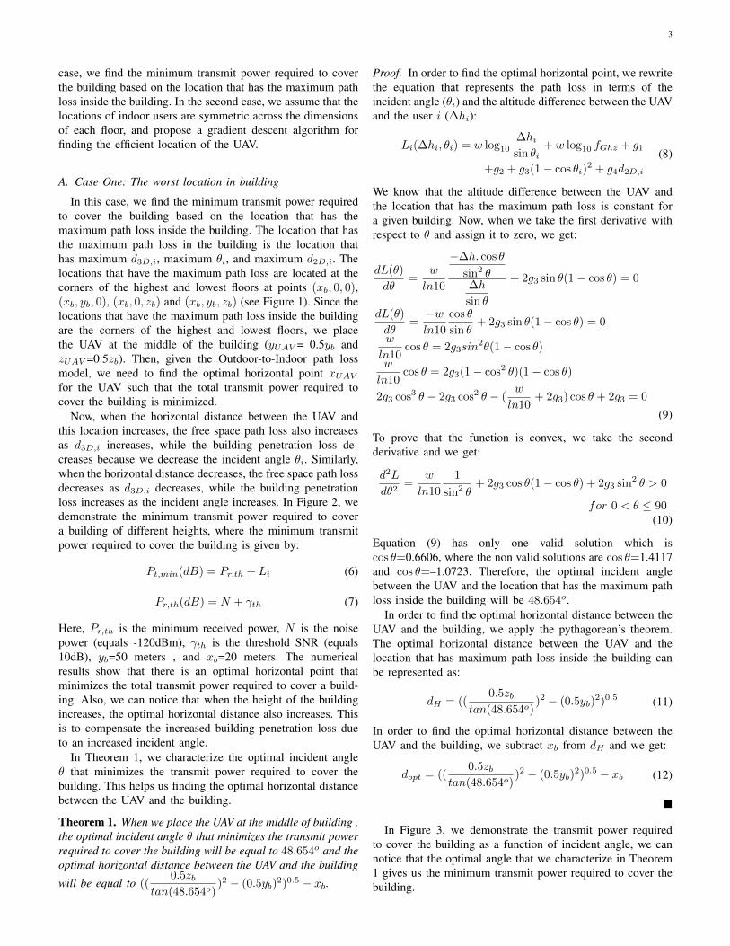
Now, when the horizontal distance between the UAV andthis location increases, the free space path loss also increasesas d3D,i increases, while the building penetration loss de-creases because we decrease the incident angle θi. Similarly,when the horizontal distance decreases, the free space path lossdecreases as d3D,i decreases, while the building penetrationloss increases as the incident angle increases. In Figure 2, wedemonstrate the minimum transmit power required to covera building of different heights, where the minimum transmitpower required to cover the building is given by:
Pt,min(dB) = Pr,th + Li (6)
Pr,th(dB) = N + γth (7)
Here, Pr,th is the minimum received power, N is the noisepower (equals -120dBm), γth is the threshold SNR (equals10dB), yb=50 meters , and xb=20 meters. The numericalresults show that there is an optimal horizontal point thatminimizes the total transmit power required to cover a build-ing. Also, we can notice that when the height of the buildingincreases, the optimal horizontal distance also increases. Thisis to compensate the increased building penetration loss dueto an increased incident angle.
In Theorem 1, we characterize the optimal incident angleθ that minimizes the transmit power required to cover thebuilding. This helps us finding the optimal horizontal distancebetween the UAV and the building.
Theorem 1. When we place the UAV at the middle of building ,the optimal incident angle θ that minimizes the transmit powerrequired to cover the building will be equal to 48.654o and theoptimal horizontal distance between the UAV and the building
will be equal to ((0.5zb
tan(48.654o))2 − (0.5yb)
2)0.5 − xb.
Proof. In order to find the optimal horizontal point, we rewritethe equation that represents the path loss in terms of theincident angle (θi) and the altitude difference between the UAVand the user i (∆hi):
Li(∆hi, θi) = w log10
∆hisin θi
+ w log10 fGhz + g1
+g2 + g3(1− cos θi)2 + g4d2D,i
(8)
We know that the altitude difference between the UAV andthe location that has the maximum path loss is constant fora given building. Now, when we take the first derivative withrespect to θ and assign it to zero, we get:
dL(θ)
dθ=
w
ln10
−∆h. cos θ
sin2 θ∆h
sin θ
+ 2g3 sin θ(1− cos θ) = 0
dL(θ)
dθ=−wln10
cos θ
sin θ+ 2g3 sin θ(1− cos θ) = 0
w
ln10cos θ = 2g3sin
2θ(1− cos θ)
w
ln10cos θ = 2g3(1− cos2 θ)(1− cos θ)
2g3 cos3 θ − 2g3 cos2 θ − (w
ln10+ 2g3) cos θ + 2g3 = 0
(9)
To prove that the function is convex, we take the secondderivative and we get:
d2L
dθ2=
w
ln10
1
sin2 θ+ 2g3 cos θ(1− cos θ) + 2g3 sin2 θ > 0
for 0 < θ ≤ 90(10)
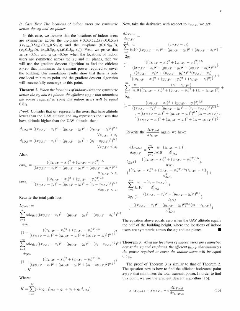
Equation (9) has only one valid solution which iscos θ=0.6606, where the non valid solutions are cos θ=1.4117and cos θ=–1.0723. Therefore, the optimal incident anglebetween the UAV and the location that has the maximum pathloss inside the building will be 48.654o.
In order to find the optimal horizontal distance between theUAV and the building, we apply the pythagorean’s theorem.The optimal horizontal distance between the UAV and thelocation that has maximum path loss inside the building canbe represented as:
dH = ((0.5zb
tan(48.654o))2 − (0.5yb)
2)0.5 (11)
In order to find the optimal horizontal distance between theUAV and the building, we subtract xb from dH and we get:
dopt = ((0.5zb
tan(48.654o))2 − (0.5yb)
2)0.5 − xb (12)
�
In Figure 3, we demonstrate the transmit power requiredto cover the building as a function of incident angle, we cannotice that the optimal angle that we characterize in Theorem1 gives us the minimum transmit power required to cover thebuilding.
4
B. Case Two: The locations of indoor users are symmetricacross the xy and xz planes
In this case, we assume that the locations of indoor usersare symmetric across the xy-plane ((0,0,0.5zb),(xb,0,0.5zb),(xb,yb,0.5zb),(0,yb,0.5zb))) and the xz-plane ((0,0.5yb,0),(xb,0.5yb,0), (xb,0.5yb,zb),(0,0.5yb,zb)). First, we prove thatzUAV =0.5zb and yUAV =0.5yb when the locations of indoorusers are symmetric across the xy and xz planes, then wewill use the gradient descent algorithm to find the efficientxUAV that minimizes the transmit power required to coverthe building. Our simulation results show that there is onlyone local minimum point and the gradient descent algorithmwill successfully converge to this point.
Theorem 2. When the locations of indoor users are symmetricacross the xy and xz planes, the efficient zUAV that minimizesthe power required to cover the indoor users will be equal0.5zb.
Proof. Consider that m1 represents the users that have altitudelower than the UAV altitude and m2 represents the users thathave altitude higher than the UAV altitude, then:
d3D,i = ((xUAV − xi)2 + (yUAV − yi)2 + (zUAV − zi)2)0.5
∀zUAV > zi
d3D,i = ((xUAV − xi)2 + (yUAV − yi)2 + (zi − zUAV )2)0.5
∀zUAV < zi
Also,
cosθi =((xUAV − xi)2 + (yUAV − yi)2)0.5
((xUAV − xi)2 + (yUAV − yi)2 + (zUAV − zi)2)0.5
∀zUAV > zi
cosθi =((xUAV − xi)2 + (yUAV − yi)2)0.5
((xUAV − xi)2 + (yUAV − yi)2 + (zi − zUAV )2)0.5
∀zUAV < zi
Rewrite the total path loss:
LTotal =m1∑i=1
wlog10((xUAV − xi)2 + (yUAV − yi)2 + (zUAV − zi)2)0.5
+g3.
(1− ((xUAV − xi)2 + (yUAV − yi)2)0.5
((xUAV − xi)2 + (yUAV − yi)2 + (zUAV − zi)2)0.5)2
m2∑i=1
wlog10((xUAV − xi)2 + (yUAV − yi)2 + (zi − zUAV )2)0.5
+g3.
(1− ((xUAV − xi)2 + (yUAV − yi)2)0.5
((xUAV − xi)2 + (yUAV − yi)2 + (zi − zUAV )2)0.5)2
+K
Where:
K =
M∑i=1
(wlog10fGhz + g1 + g2 + g4d2D,i)
Now, take the derivative with respect to zUAV , we get:
dLTotaldzUAV
=
m1∑i=1
w
ln10
(zUAV − zi)((xUAV − xi)2 + (yUAV − yi)2 + (zUAV − zi)2)
+
2g3.
(1− ((xUAV − xi)2 + (yUAV − yi)2)0.5
((xUAV − xi)2 + (yUAV − yi)2 + (zUAV − zi)2)0.5).
(((xUAV − xi)2 + (yUAV − yi)2)0.5(zUAV − zi)
((xUAV − xi)2 + (yUAV − yi)2 + (zUAV − zi)2)32
) +
m2∑i=1
w
ln10
−(zi − zUAV )
((xUAV − xi)2 + (yUAV − yi)2 + (zi − zUAV )2)+
2g3.
(1− ((xUAV − xi)2 + (yUAV − yi)2)0.5
((xUAV − xi)2 + (yUAV − yi)2 + (zi − zUAV )2)0.5).
(−((xUAV − xi)2 + (yUAV − yi)2)0.5(zi − zUAV )
((xUAV − xi)2 + (yUAV − yi)2 + (zi − zUAV )2)32
)
Rewrite thedLTotaldzUAV
again, we have:
dLTotaldzUAV
=
m1∑i=1
w
ln10
(zUAV − zi)d23D,i
+
2g3.(1−((xUAV − xi)2 + (yUAV − yi)2)0.5
d3D,i).
(((xUAV − xi)2 + (yUAV − yi)2)0.5(zUAV − zi)
d33D,i) +
m2∑i=1
w
ln10
−(zi − zUAV )
d23D,i+
2g3.(1−((xUAV − xi)2 + (yUAV − yi)2)0.5
d3D,i).
(−((xUAV − xi)2 + (yUAV − yi)2)0.5(zi− zUAV )
d33D,i)
The equation above equals zero when the UAV altitude equalsthe half of the building height, where the locations of indoorusers are symmetric across the xy and xz planes. �
Theorem 3. When the locations of indoor users are symmetricacross the xy and xz planes, the efficient yUAV that minimizesthe power required to cover the indoor users will be equal0.5yb.
The proof of Theorem 3 is similar to that of Theorem 2.The question now is how to find the efficient horizontal pointxUAV that minimizes the total transmit power. In order to findthis point, we use the gradient descent algorithm [16]:
xUAV,n+1 = xUAV,n − adLTotaldxUAV,n
(13)

5
Fig. 4: Total path loss for different building heights
Where:
dLTotaldxUAV
=
M∑i=1
w
ln10
−(xi − xUAV )
d23D,i+
2g3.(1−((xi − xUAV )2 + (yi − yUAV )2)0.5
d3D,i).
((xi − xUAV )d3D,i((xi − xUAV )2 + (yi − yUAV )2)−0.5
d23D,i−
((xi − xUAV )2 + (yi − yUAV )2)0.5(xi − xUAV )d−13D,i
d23D,i)
a: the step size.d3D,i=((xi − xUAV )2 + (yi − yUAV )2 + (zi − zUAV )2)0.5
The pseudo code of this algorithm is shown in Algorithm1.
Algorithm 1 Efficient xUAV using gradient descent algorithmInput:The 3D locations of the users inside the building.The step size a, the step tolerance ε.The dimensions of the building [0, xb] × [0, yb] × [0, zb].The maximum number of iterations Nmax.Initialize xUAVFor n=1,2,..., Nmax
xUAV,n+1 ← xUAV,n− adLTotaldxUAV,n
If ‖ xUAV,n − xUAV,n+1 ‖ < εReturn: xUAV,opt = xUAV,n+1
End for
V. NUMERICAL RESULTS
In this section, we verify our results for the second case. Weassume that each floor contains 20 users. Then, we apply the
gradient descent algorithm to find the efficient horizontal pointxUAV that minimizes the transmit power required to cover theindoor users. Table I lists the parameters used in the numericalanalysis.
TABLE I: Parameters in numerical analysis
Height of building zb 200 meters, 250 meters and 300 meters
Horizontal width of building xb 10 meters, 20 meters and 50 meters
Vertical width of building yb 50 meters
Hight of each floor 5 meters
Step size a 0.01
Maximum number of iterations Nmax 500
The carrier frequency fGhz 2Ghz
Number of users in each floor 20 users
In Figure 4, we find the efficient horizontal points fora building of different heights. In the upper part of thefigures, we find the total path loss at different locations(xUAV ,0.5yb,zUAV ) and in the lower part of the figures, wefind the efficient horizontal point xUAV that results in the min-imum total path loss using the gradient descent algorithm. Ascan be seen from the figures, when the height of the buildingincreases, the efficient horizontal point xUAV increases. Thisis to compensate the increased building penetration loss dueto an increased incident angle.
In Figure 5, we investigate the impact of different buildingwidths (i.e., xb). We fix the building height to be 250 metersand vary the building width. As can be seen from the figures,when the building width increases, the efficient horizontaldistance decreases. This is to compensate the increased indoorpath loss due to an increased building width.
In [17], we validate the simulation results by using theparticle swarm optimization algorithm and study the problemwhen the locations of indoor users are uniformly distributedin each floor.

6
Fig. 5: Total path loss for different building widths
VI. CONCLUSION
In this paper, we study the problem of providing wirelesscoverage for users inside a high-rise building using a singleUAV. First, we demonstrate why the Air-to-Ground path lossmodel is not appropriate for considering indoor users with3D locations. Then, we present the Outdoor-to-Indoor pathloss model, show the tradeoff in this model, and study theproblem of minimizing the transmit power required to coverthe building. Due to the intractability of the problem, we studythe efficient placement of the UAV under two cases. In the firstcase, we find the minimum transmit power required to coverthe building based on the location that has the maximum pathloss inside the building. In the second case, we assume thatthe locations of indoor users are symmetric across the xy andxz planes and we use the gradient descent algorithm to findthe efficient placement of the UAV. In order to model morerealistic scenarios, we will consider different types of userdistribution in our future work. We will also study the problemof providing wireless coverage using multiple UAVs.
ACKNOWLEDGMENT
This work was supported in part by the NSF under GrantsCNS-1647170 and CNS-1651947.
REFERENCES
[1] P. Bupe, R. Haddad, and F. Rios-Gutierrez, “Relief and emergencycommunication network based on an autonomous decentralized uavclustering network,” in SoutheastCon 2015. IEEE, 2015, pp. 1–8.
[2] R. I. Bor-Yaliniz, A. El-Keyi, and H. Yanikomeroglu, “Efficient 3-dplacement of an aerial base station in next generation cellular networks,”in Communications (ICC), 2016 IEEE International Conference on.IEEE, 2016, pp. 1–5.
[3] A. Al-Hourani, S. Kandeepan, and A. Jamalipour, “Modeling air-to-ground path loss for low altitude platforms in urban environments,” in2014 IEEE Global Communications Conference. IEEE, 2014, pp. 2898–2904.
[4] M. Mozaffari, W. Saad, M. Bennis, and M. Debbah, “Drone small cellsin the clouds: Design, deployment and performance analysis,” in IEEEGlobal Communications Conference (GLOBECOM), 2015, pp. 1–6.
[5] M. Mozaffari, W. Saad, M. Bennis, and M. Debbah, “Optimal trans-port theory for power-efficient deployment of unmanned aerial vehi-cles,” IEEE International Conference on Communications (ICC), KualaLumpur, Malaysia,, 2016.
[6] M. Mozaffari, W. Saad, M. Bennis, and M. Debbah, “Efficient de-ployment of multiple unmanned aerial vehicles for optimal wirelesscoverage,” arXiv preprint arXiv:1606.01962, 2016.
[7] E. Kalantari, H. Yanikomeroglu, and A. Yongacoglu, “On the numberand 3d placement of drone base stations in wireless cellular networks,”in IEEE Vehicular Technology Conference, 2016, pp. 18–21.
[8] H. Shakhatreh, A. Khreishah, J. Chakareski, H. B. Salameh, andI. Khalil, “On the continuous coverage problem for a swarm of uavs,”in Sarnoff Symposium, 2016 IEEE 37th. IEEE, 2016, pp. 130–135.
[9] “Ericsson report optimizing the indoor experience,http://www.ericsson.com/res/docs/2013/real-performance-indoors.pdf,”2013.
[10] “In-building wireless: One size does not fit all, http://www.alcatel-lucent.com/solutions/in-building/in-building-infographic.”
[11] “Cisco service provider wi-fi: A platform forbusiness innovation and revenue generation,http://www.cisco.com/c/en/us/solutions/collateral/service-provider/service-provider-wi-fi/solution overview c22 642482.html.”
[12] “Using high-power das in high-rise buildings,http://www.commscope.com/docs/using-high-power-das-in-high-rise-buildings-an-318376-ae.pdf.”
[13] “Coverage solution for high-rise building,http://www.amplitec.net/products-2-coverage-solution-for-high-rise-building.html.”
[14] S. Zhang, Z. Zhao, H. Guan, and H. Yang, “Study on mobile dataoffloading in high rise building scenario,” in Vehicular TechnologyConference (VTC Spring), 2016 IEEE 83rd. IEEE, 2016, pp. 1–5.
[15] M. Series, “Guidelines for evaluation of radio interface technologies forimt-advanced,” Report ITU, no. 2135-1, 2009.
[16] R. S. Sutton and A. G. Barto, Reinforcement learning: An introduction.MIT press Cambridge, 1998, vol. 1, no. 1.
[17] H. Shakhatreh, A. Khreishah, A. Alsarhan, I. Khalil, A. Sawalmeh,and O. Noor Shamsiah, “Efficient 3d placement of a uav using particleswarm optimization,” in The International Conference on Informationand Communication Systems (ICICS 2017) (accepted).