Embed Size (px)
Citation preview
Simulation and Control of Mini UAVs
ANDREA SANNA† and BARBARA PRALIO‡ †Dipartimento di Automatica e Informatica
‡Dipartimento di Ingegneria Aeronautica e Spaziale Politecnico di Torino
Corso Duca degli Abruzzi 24, I-10129, Torino ITALY
Abstract: - The capabilities to perform missions in hostile and/or hardly accessible areas reducing human risks are responsible of the growing interest in Uninhabited Air Vehicles (UAVs) characterizing the last years. Recent advances in Information and Communication Technologies have allowed to scale sizes of uninhabited aerial platforms, and hence to perform mission profiles not possible for conventional aircraft. Within UAVs applications, the remote piloting and/or monitoring issues play a key role in the ground control station design and ground operator(s) training. This paper presents the issues related to the simulation and the remote control of a mini UAV for environmental monitoring. The simulation tool is developed to support ground control station design and virtual and real ground operator training. The project requirement of a single operator for flight and mission management influences the human-machine interface and the devices for remote control. Non conventional devices, such as digital wearable technologies, are used within the simulator and tested also for real piloting interface. Key-Words: - flight simulation, mini UAVs, human-machine interface. 1 Introduction UAVs are aircraft without crew and passengers that could either be remotely piloted by ground or autonomously carry out a mission profile. Their effectiveness is due to the possibility to reach hostile and inaccessible areas without exposing humans to hazards and dangerous situations. Moreover, the internal space can be fully designed in order to place payload (sensors and /or cameras) and the on-board systems. UAVs actually represent one of the most important technology in the aeronautic field due to their application flexibility, mission reconfigurability and, above all, for the trade-off between mission costs and performances [1]. The employment of UAVs mainly involves military tasks, but civilian applications are rapidly grow in the last years. Some examples are search and localization of missing people, fire prevention, aerial photography, traffic control, air quality monitoring in urban sites, and monitoring of acoustic and sea pollution [2]. The proposed work is a part of a larger project aimed to design and develop a mini Uninhabited Air Vehicle (in the following of the paper the terms UAV and platform will be used as synonymous) and its ground control station devoted to environmental monitoring. The key issue tackled in this paper is the human-machine interface involved in the management of the UAV, both in remotely piloted and autonomous flight mode. Usual approaches to remote control of mobile platforms involve analog remote controls and direct visual feedback: the control station is provided with one or more cloches and visual contact is the main source of feedback for the operator, who relies on his/her experience to visually drive the mobile device toward its target. Instrumental control (i.e. without any direct visual contact with the mobile device) has
been exploited in unmanned vehicles, but when involved dynamics become very fast (such as in the case of a flying platform), a number of significant issues come up and several of them being related to human-computer interaction. Since the control depends on human actions, a fast and reliable communication must be assured between the human operator and the computer, in order to build a reliable and efficient control chain. Thus data acquisition, merging and presentation becomes crucial as well as user action detection and interpretation. A wide spectrum of research has been conducted in the past years about remote flight control and unmanned platforms for remote sensing [3][4], even supporting joint decision from both human and computer in controlling the platform [5]; nevertheless, very few projects have been fully developed up to a working prototype as regards advanced, non-legacy human-computer interfaces [6][7]. The problem of receiving input from the user is still basically open. On one side, a number of approaches are still based on the traditional paradigms (for instance, keyboard and mouse). On the other hand, such devices require a considerable effort in terms of training and their use is not natural to control a UAV in real time. A strong effort has been devoted in the last years to the development of gesture-based human-computer interaction: being able to decode user gestures would let the user to control the platform in a very natural and straightforward way, thus not needing long training periods. A number of studies have made use of glove-based devices [8][9] to measure the position and posture of a user's hand, the angle between adjacent fingers being measured by means of additional sensors, usually mechanical or optical. These techniques have been quite successful, especially in the field of virtual reality. Glove-
Proceedings of the 5th WSEAS Int. Conf. on SIMULATION, MODELING AND OPTIMIZATION, Corfu, Greece, August 17-19, 2005 (pp129-135)
based devices provide estimation of the position and location of a hand with a good degree of accuracy and excellent response times. In this paper a simulation environment is presented, involving both flight and mission management. The simulation tool is addressed to the design of the ground control station of an uninhabited aerial platform and to the training of the ground operator in a virtual environment. As to the former objective, the attention is focused on the remote control devices (RC transmitter, joystick, data glove) and the effectiveness of operator’s “point of view” (internal, external, on the ground). The data visualization and their presentation to the human operator are also analyzed. The training of the user represents a further step in the simulation tool application and implies a trade-off between fidelity of aircraft (and related subsystems) model and virtual scenario reconstruction and real-time simulation constraints. The present paper will focus on the issues related to the ground control station design, providing a look to the aerial platform mathematical model, to the implementation of different remote control devices and to the management of flight by the ground operator, with particular attention to the training issues. The paper is organized as follows: Section 2 presents the whole framework while Section 3 is focused on the flight simulator architecture; in particular, it presents some details of the aerial platform mathematical model and the scenario rendering engine. Section 4 reports the remote control modes and devices being analyzed as representing the human-machine interface. Finally, Section 5 outlines the issues related to the implementation of non conventional devices to the real piloting interface. 2 The whole scenario The Italian research Ministry (MIUR), in the frame of the project Cofin 2004, has recently co-founded a project that involves three Departments of Politecnico di Torino and Universities of Pavia, Messina, and Catania. The project aims to design and develop a platform for environmental monitoring, involving applications such as fire detection and prevention, industrial areas reconnaissance, and natural disaster monitoring. An aerial platform of as small size and weight as compatible to mission requirements is chosen to carry on-board sensors and cameras in order to provide the user real time information about the territory under monitoring. The mission requirements include capability of both remotely piloted flight and autonomous flight due to the variety of applications. It is worth to note that the ground operator has to acquire the skills for a real-time mission re-planning of autonomous flight, on the base of data elaboration results. On the opposite of ground control stations traditionally used for this kind of platform, the goal of the project is to enable a single operator to manage the whole mission profile (i.e. piloting the UAV when it is not flying in an autonomous way, checking data coming from
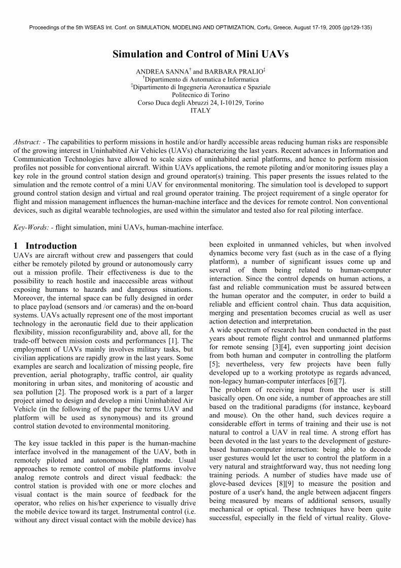
sensors and cameras, reprogramming the mission plane, and so on). The platform configuration and performances, as well as the communication system, the flight control system design, and the treatment of data are out of the scope of this paper. On the other hand, this work is aimed to present the simulation environment developed for training operators in the piloting and in mission management. 3 The flight simulator architecture The flight simulator architecture is shown in Fig. 1. A set of input devices (keyboard, joystick, data glove, and remote radio control) allows the user to pilot the UAV. The simulator can be considered as a system composed of two modules: the dynamic model of the aircraft the rendering of a virtual scenario. A set of input files is loaded at the beginning of a simulation session; these files describe both the geometry of the scenario and the aircraft configuration.
3.1 The aircraft mathematical model Since the mathematical model of the platform plays a key role in the simulation fidelity and strongly affects training results, a brief description of the aircraft dynamics model will be provided. The aerial platform dynamics are implemented within the flight simulator structure by a complete 6 DoF nonlinear mathematical model [10]. The rigid body assumption is made, neglecting structural flexibility: this assumption is commonly applied for general flight simulation application, as attention is focused on trajectory analysis and overall aircraft performances, and it is further supported in this contest of simulation of a mini uninhabited aerial vehicle, characterized by small dimensions and weight. The flat and nonrotating Earth assumption is also applied; it does not affect model fidelity for low speed flight simulation, interesting small areas and
Figure 1: the flight simulator architecture.
Proceedings of the 5th WSEAS Int. Conf. on SIMULATION, MODELING AND OPTIMIZATION, Corfu, Greece, August 17-19, 2005 (pp129-135)
with no requirements for a precise navigation task. The aircraft translational and rotational dynamics are modeled by force and moment equations, respectively:
[ ]BBBBB FVBFCGFTAFCG gTvF
mv 11 −+Ω−= ω
~,&
[ ] [ ]
Ω−= −
BBBB FFTAF IMI ωω ω~
,1&
where vCG and ω represent the aircraft center of gravity linear velocity and the aircraft angular velocity, respectively. The body-axes reference frame, i.e. a vehicle body-fixed system, having origin at the vehicle center of gravity and axes aligned with vehicle reference directions, is considered for the mathematical model. The vehicle attitude is modeled by the Euler kinematical equations:
( )[ ]BFH ωΦ=Φ&
where Φ represents the Euler angles vector, consisting of roll (φ), pitch (θ) and yaw (ψ) angles. The navigation task is accomplished by considering the navigation equations, expressed in terms of aircraft center of gravity position with reference to a geographic system having origin at the vehicle center of gravity:
[ ]BV FCGVBFCG vTp =&
The complete mathematical model is hence represented by twelve, coupled, nonlinear, ordinary differential equations. The aircraft maneuver response is obtained by applying a numerical integration algorithm, based on a fourth order Runge-Kutta scheme, to solving simultaneously the complete system. The aerial platform is characterized by the aerodynamic model and the propulsive system model. The former one is based on an experimentally derived dataset of stability and control derivatives. The aerodynamic forces (FA) and moments (MA) are obtained by modeling the dependencies on flight condition, aerodynamic angles and control surface deflections. As to the propulsive system module, linear relationships were applied to model the voltage supply and current drain trend of variation for a DC motor-based propulsion. The propeller performance are estimated by implementing the blade element theory to compute propulsive forces (FT) and moments (MT) at a given regime of rotation. The propeller model is directly related to the power control (throttle command) while the DC motor modeling relationships provide information on the supply conditions and the energy source (battery) status. These information belong to the set of data the graphical user interface provide to the
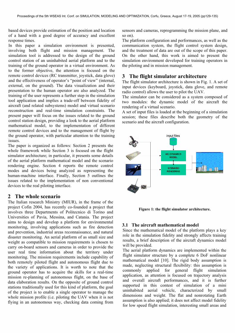
ground operator, together with aircraft attitude and flight condition data. The aerodynamic and propulsive load models are then combined to the vector equations to obtain the complete aircraft model formulation. As well as the aircraft dynamics, the atmospheric turbulence, including gusts and/or steady winds, is modeled within the present flight simulation tool. It enhances flight simulation fidelity allowing to evaluate the vehicle performance and maneuver response dynamics also when ideally calm air conditions are not verified. Fig. 2 shows the data flow within the mathematical model architecture.
The main control commands are represented by the stick input and the throttle input. The former one is directly related to the control surfaces deflection, that, according to the present aerial platform, are aileron and elevator for longitudinal and lateral-directional control, respectively. The stick input enters the aerodynamic model determining, together with aircraft states, the aerodynamic loads (FA, MA). On the other hand, the throttle input represents the power control and, as a consequence, it is involved in the computation of the propulsive loads (FT, MT). The control commands, quite apart from the ground operator interface (RC transmitter, joystick, data glove), are provided to the mathematical model as angular deflection of control surfaces and percentage of maximum regime of rotation of the propulsive system. 3.2 Scenario rendering engine The rendering engine is entirely based on OpenGL [11], Glut [12], and PLIB [13] libraries and it is therefore platform independent. The scenario is implemented by altitude maps (we have planned the introduction of real DEMs – Digital Elevation Maps – of Italy) organized in tiles. Tiles are dynamically loaded and rendered according the position and orientation of the aircraft. Buildings, trees, and other 3D objects are inserted to allow the user to do more realistic and effective training sessions. PLIB and Glut allow to manage input devices, sounds, rendering levels of
Figure 2: mathematical model architecture.
Proceedings of the 5th WSEAS Int. Conf. on SIMULATION, MODELING AND OPTIMIZATION, Corfu, Greece, August 17-19, 2005 (pp129-135)
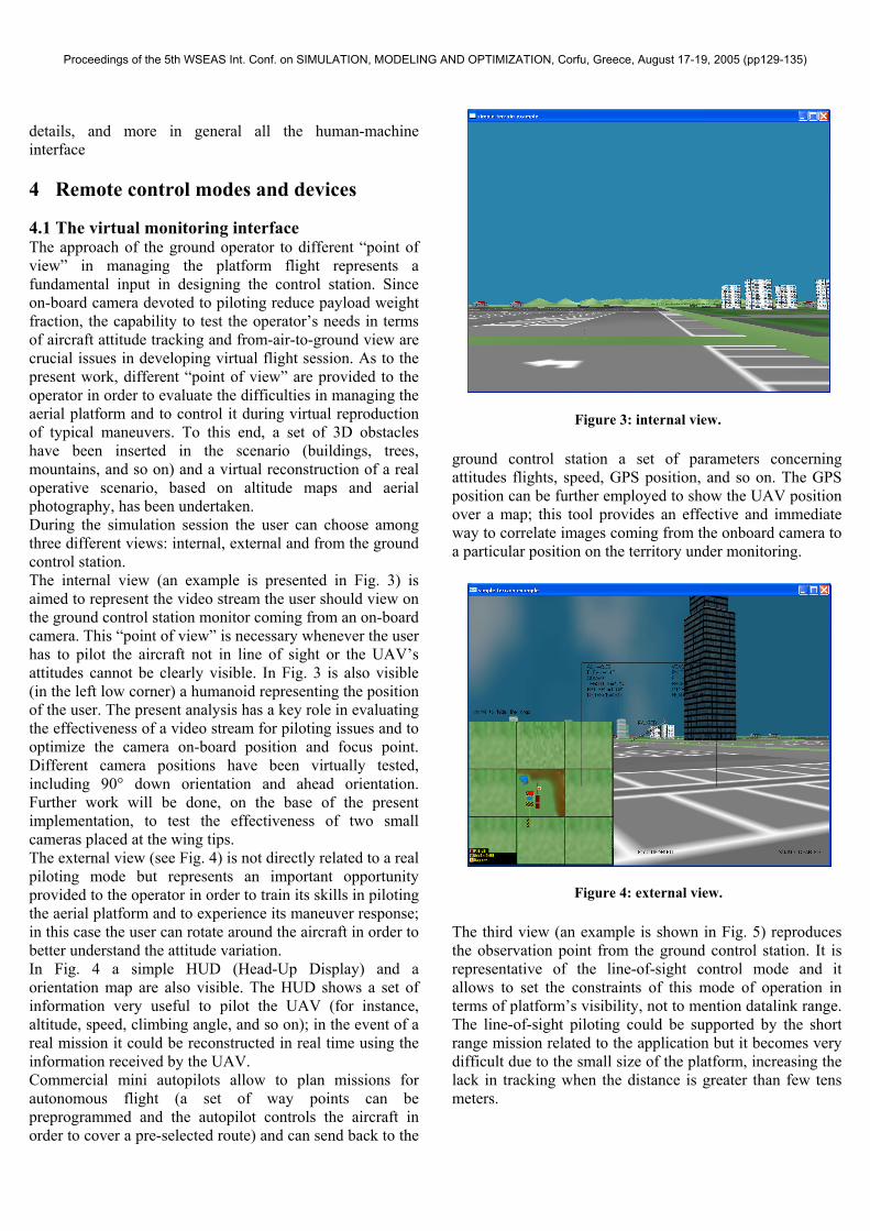
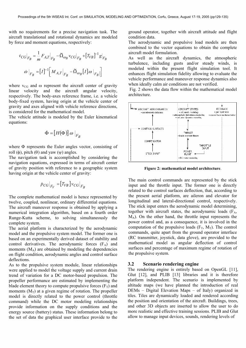
details, and more in general all the human-machine interface 4 Remote control modes and devices 4.1 The virtual monitoring interface The approach of the ground operator to different “point of view” in managing the platform flight represents a fundamental input in designing the control station. Since on-board camera devoted to piloting reduce payload weight fraction, the capability to test the operator’s needs in terms of aircraft attitude tracking and from-air-to-ground view are crucial issues in developing virtual flight session. As to the present work, different “point of view” are provided to the operator in order to evaluate the difficulties in managing the aerial platform and to control it during virtual reproduction of typical maneuvers. To this end, a set of 3D obstacles have been inserted in the scenario (buildings, trees, mountains, and so on) and a virtual reconstruction of a real operative scenario, based on altitude maps and aerial photography, has been undertaken. During the simulation session the user can choose among three different views: internal, external and from the ground control station. The internal view (an example is presented in Fig. 3) is aimed to represent the video stream the user should view on the ground control station monitor coming from an on-board camera. This “point of view” is necessary whenever the user has to pilot the aircraft not in line of sight or the UAV’s attitudes cannot be clearly visible. In Fig. 3 is also visible (in the left low corner) a humanoid representing the position of the user. The present analysis has a key role in evaluating the effectiveness of a video stream for piloting issues and to optimize the camera on-board position and focus point. Different camera positions have been virtually tested, including 90° down orientation and ahead orientation. Further work will be done, on the base of the present implementation, to test the effectiveness of two small cameras placed at the wing tips. The external view (see Fig. 4) is not directly related to a real piloting mode but represents an important opportunity provided to the operator in order to train its skills in piloting the aerial platform and to experience its maneuver response; in this case the user can rotate around the aircraft in order to better understand the attitude variation. In Fig. 4 a simple HUD (Head-Up Display) and a orientation map are also visible. The HUD shows a set of information very useful to pilot the UAV (for instance, altitude, speed, climbing angle, and so on); in the event of a real mission it could be reconstructed in real time using the information received by the UAV. Commercial mini autopilots allow to plan missions for autonomous flight (a set of way points can be preprogrammed and the autopilot controls the aircraft in order to cover a pre-selected route) and can send back to the
ground control station a set of parameters concerning attitudes flights, speed, GPS position, and so on. The GPS position can be further employed to show the UAV position over a map; this tool provides an effective and immediate way to correlate images coming from the onboard camera to a particular position on the territory under monitoring.
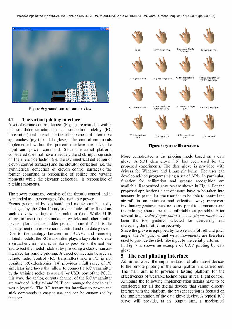
The third view (an example is shown in Fig. 5) reproduces the observation point from the ground control station. It is representative of the line-of-sight control mode and it allows to set the constraints of this mode of operation in terms of platform’s visibility, not to mention datalink range. The line-of-sight piloting could be supported by the short range mission related to the application but it becomes very difficult due to the small size of the platform, increasing the lack in tracking when the distance is greater than few tens meters.
Figure 3: internal view.
Figure 4: external view.
Proceedings of the 5th WSEAS Int. Conf. on SIMULATION, MODELING AND OPTIMIZATION, Corfu, Greece, August 17-19, 2005 (pp129-135)
4.2 The virtual piloting interface A set of remote control devices (Fig. 1) are available within the simulator structure to test simulation fidelity (RC transmitter) and to evaluate the effectiveness of alternative approaches (joystick, data glove). The control commands implemented within the present interface are stick-like input and power command. Since the aerial platform considered does not have a rudder, the stick input consists of the aileron deflection (i.e. the asymmetrical deflection of elevon control surfaces) and the elevator deflection (i.e. the symmetrical deflection of elevon control surfaces); the former command is responsible of rolling and yawing moments while the elevator deflection is responsible of pitching moments. The power command consists of the throttle control and it is intended as a percentage of the available power. Events generated by keyboard and mouse can be easily managed by the Glut library and include utility functions such as view settings and simulation data. While PLIB allows to insert in the simulator joysticks and other similar devices (for instance rudder pedals), more difficult is the management of a remote radio control and of a data glove. Due to the analogy between mini-UAVs and remotely piloted models, the RC transmitter plays a key role to create a virtual environment as similar as possible to the real one and to test the model fidelity, by providing a classic human-interface for remote piloting. A direct connection between a remote radio control (RC transmitter) and a PC is not possible. RC-Electronics [14] provides a full range of PC simulator interfaces that allow to connect a RC transmitter by the training socket to a serial (or USB) port of the PC. In this way, the analog outputs channel of the RC transmitter are traduced in digital and PLIB can manage the device as it was a joystick. The RC transmitter interface to power and stick commands is easy-to-use and can be customized by the user.
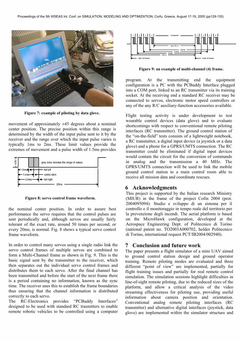
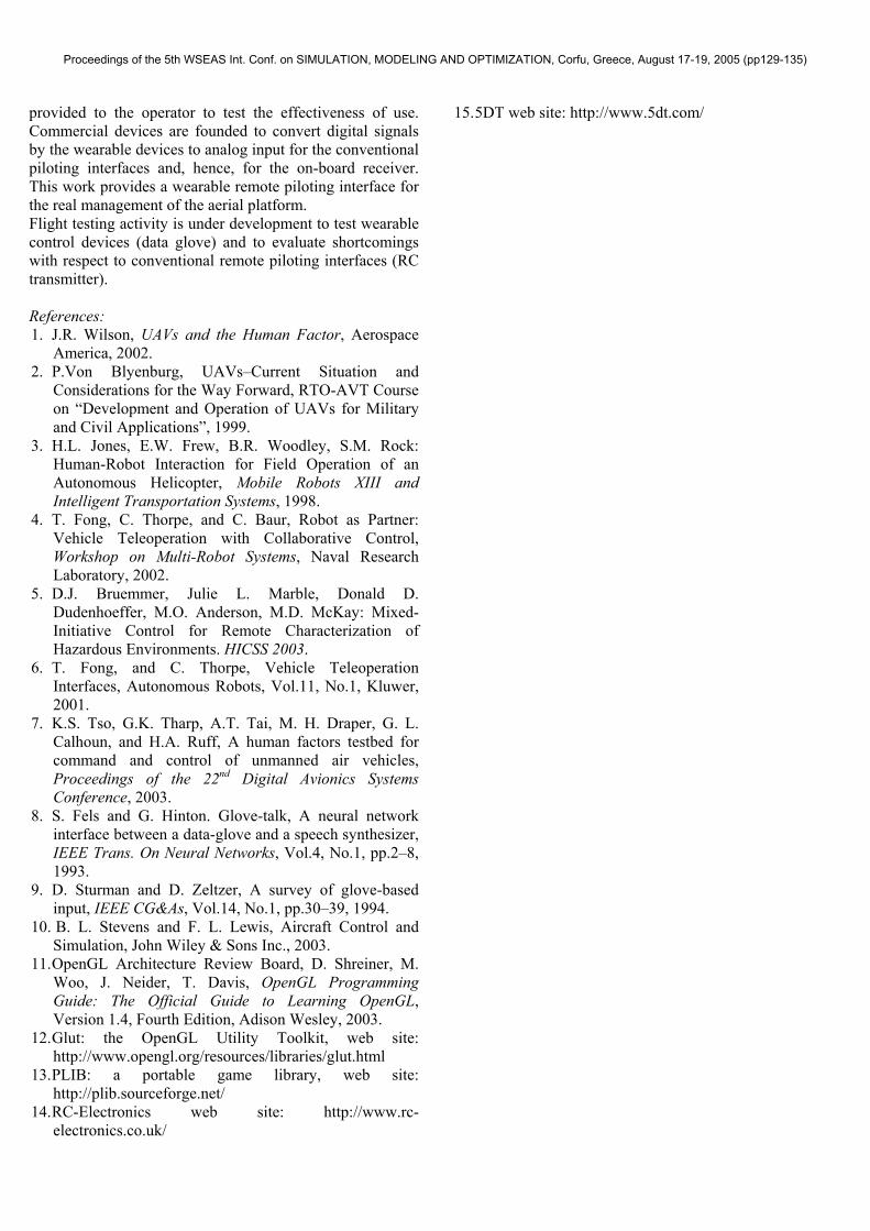
More complicated is the piloting mode based on a data glove. A 5DT data glove [15] has been used for the proposed experiments. The data glove is provided with drivers for Windows and Linux platforms. The user can develop ad-hoc programs using a set of APIs. In particular, function for calibration and gesture recognition are available. Recognized gestures are shown in Fig. 6. For the proposed applications a set of issues have to be taken into account. In particular, the user has to be able to control the aircraft in an intuitive and effective way; moreover, involuntary gestures must not correspond to commands and the piloting should be as comfortable as possible. After several tests, index finger point and two finger point have been the two gestures selected for decreasing and increasing the throttle, respectively. Since the glove is equipped by two sensors of roll and pitch angle, the fist gesture and wrist movements are therefore used to provide the stick-like input to the aerial platform. In Fig. 7 is shown an example of UAV piloting by data glove. 5 The real piloting interface As further work, the implementation of alternative devices to the remote piloting of the aerial platform is carried out. The main aim is to provide a testing platform for the effectiveness of wearable technologies in real flight control. Although the following implementation details have to be considered for all the digital devices that cannot directly interact with the platform, the present section is focused on the implementation of the data glove device. A typical R/C servo will provide, at its output arm, a mechanical
Figure 6: gesture illustrations.
Figure 5: ground control station view.
Proceedings of the 5th WSEAS Int. Conf. on SIMULATION, MODELING AND OPTIMIZATION, Corfu, Greece, August 17-19, 2005 (pp129-135)
movement of approximately ±45 degrees about a nominal center position. The precise position within this range is determined by the width of the input pulse sent to it by the receiver and the range over which the input pulse varies is typically 1ms to 2ms. These limit values provide the extremes of movement and a pulse width of 1.5ms provides
the nominal center position. In order to assure best performance the servo requires that the control pulses are sent periodically and, although servos are usually fairly tolerant of the exact rate, around 50 times per second, or every 20ms, is normal. Fig. 8 shows a typical servo control frame waveform. In order to control many servos using a single radio link the servo control frames of multiple servos are combined to form a Multi-Channel frame as shown in Fig. 9. This is the basic signal sent by the transmitter to the receiver, which then separates out the individual servo control frames and distributes them to each servo. After the final channel has been transmitted and before the start of the next frame there is a period containing no information, known as the sync time. The receiver uses this to establish the frame boundaries thus ensuring that the channel information is distributed correctly to each servo. The RC-Electronics provides “PCBuddy Interfaces” designed to be used with standard RC trasmitters to enable remote robotic vehicles to be controlled using a computer
program. At the transmitting end the equipment configuration is a PC with the PCBuddy Interface plugged into a COM port, linked to an RC transmitter via its training socket. At the receiving end a standard RC receiver may be connected to servos, electronic motor speed controllers or any of the any R/C auxiliary-function accessories available. Flight testing activity is under development to test wearable control devices (data glove) and to evaluate shortcomings with respect to conventional remote piloting interfaces (RC transmitter). The ground control station of the “on-the-field” tests consists of a lightweight notebook, a RC transmitter, a digital input device (a joystick or a data glove) and a phone for a GPRS/UMTS connection. The RC transmitter could be eliminated if digital input devices would contain the circuit for the conversion of commands in analog and the transmission a 40 MHz. The GPRS/UMTS connection will be used to link the mobile ground control station to a main control room able to receive all mission data and coordinate rescues.
6 Acknowledgments This project is supported by the Italian research Ministry (MIUR) in the frame of the project Cofin 2004 (prot. 2004095094): Studio e sviluppo di un sistema per il controllo e il monitoraggio in tempo reale del territorio per la prevenzione degli incendi. The aerial platform is based on the MicroHawk configuration, developed at the Aerospace Engineering Dept. of Politecnico di Torino (national patent no. TO2003A000702, holder Politecnico di Torino, international request PCT/IB2004/002940). 7 Conclusion and future work The paper presents a flight simulator of a mini UAV aimed to ground control station design and ground operator training. Remote piloting modes are evaluated and three different “point of view” are implemented, partially for flight training issues and partially for real remote control simulation. The simulation sessions highlight difficulties in line-of-sight remote piloting, due to the reduced sizes of the platform, and allow a critical analysis of the video streaming effectiveness for piloting use, providing useful information about camera position and orientation. Conventional analog remote piloting interfaces (RC transmitter) and alternative digital interfaces (joystick, data glove) are implemented within the simulator structure and
Figure 8: servo control frame waveform.
Figure 9: an example of multi-channel (4) frame.
Figure 7: example of piloting by data glove.
Proceedings of the 5th WSEAS Int. Conf. on SIMULATION, MODELING AND OPTIMIZATION, Corfu, Greece, August 17-19, 2005 (pp129-135)
provided to the operator to test the effectiveness of use. Commercial devices are founded to convert digital signals by the wearable devices to analog input for the conventional piloting interfaces and, hence, for the on-board receiver. This work provides a wearable remote piloting interface for the real management of the aerial platform. Flight testing activity is under development to test wearable control devices (data glove) and to evaluate shortcomings with respect to conventional remote piloting interfaces (RC transmitter). References: 1. J.R. Wilson, UAVs and the Human Factor, Aerospace
America, 2002. 2. P.Von Blyenburg, UAVs–Current Situation and
Considerations for the Way Forward, RTO-AVT Course on “Development and Operation of UAVs for Military and Civil Applications”, 1999.
3. H.L. Jones, E.W. Frew, B.R. Woodley, S.M. Rock: Human-Robot Interaction for Field Operation of an Autonomous Helicopter, Mobile Robots XIII and Intelligent Transportation Systems, 1998.
4. T. Fong, C. Thorpe, and C. Baur, Robot as Partner: Vehicle Teleoperation with Collaborative Control, Workshop on Multi-Robot Systems, Naval Research Laboratory, 2002.
5. D.J. Bruemmer, Julie L. Marble, Donald D. Dudenhoeffer, M.O. Anderson, M.D. McKay: Mixed-Initiative Control for Remote Characterization of Hazardous Environments. HICSS 2003.
6. T. Fong, and C. Thorpe, Vehicle Teleoperation Interfaces, Autonomous Robots, Vol.11, No.1, Kluwer, 2001.
7. K.S. Tso, G.K. Tharp, A.T. Tai, M. H. Draper, G. L. Calhoun, and H.A. Ruff, A human factors testbed for command and control of unmanned air vehicles, Proceedings of the 22nd Digital Avionics Systems Conference, 2003.
8. S. Fels and G. Hinton. Glove-talk, A neural network interface between a data-glove and a speech synthesizer, IEEE Trans. On Neural Networks, Vol.4, No.1, pp.2–8, 1993.
9. D. Sturman and D. Zeltzer, A survey of glove-based input, IEEE CG&As, Vol.14, No.1, pp.30–39, 1994.
10. B. L. Stevens and F. L. Lewis, Aircraft Control and Simulation, John Wiley & Sons Inc., 2003.
11. OpenGL Architecture Review Board, D. Shreiner, M. Woo, J. Neider, T. Davis, OpenGL Programming Guide: The Official Guide to Learning OpenGL, Version 1.4, Fourth Edition, Adison Wesley, 2003.
12. Glut: the OpenGL Utility Toolkit, web site: http://www.opengl.org/resources/libraries/glut.html
13. PLIB: a portable game library, web site: http://plib.sourceforge.net/
14. RC-Electronics web site: http://www.rc-electronics.co.uk/
15. 5DT web site: http://www.5dt.com/
Proceedings of the 5th WSEAS Int. Conf. on SIMULATION, MODELING AND OPTIMIZATION, Corfu, Greece, August 17-19, 2005 (pp129-135)