Embed Size (px)
Citation preview

INFORMA PMD-A
l
l
l
l
Power quality monitoring - IEC 61000-4-30 Class A (Edition 2.0)
Digital fault recording
Single screen power system overview
Device and communication health check
Email: info qualitrolcorp.com@
www.qualitrolcorp.com
®©2010 QUALITROL Company LLC, an ISO 9001 system certified company. All rights reserved. Information subject to change without notice.All trademarks are properties of their respective companies, as noted herein. IP-Q24-05L-01E.
About ®QUALITROL®QUALITROL
manufacturing companies. It is the global leader in sales and installations of transformer asset protection equipment, ®fault recorders and fault locators. Established in 1945, QUALITROL produces thousands of different types of products
on demand, each customized to customers’ unique requirements.
manufactures substation and transformer monitoring and protection devices used by electric utilities and
Product Summary
Performance measuring and monitoring device
Providing all the answers needed,not just data, at the click of a button
Product Summary
®QUALITROL Field Services®QUALITROL provides on-site commissioning/start-up and comprehensive maintenance contracts to all customers
worldwide. To further improve reliability, an extended warranty is available on selected products commissioned by ®QUALITROL .®QUALITROL Educational Services
®QUALITROL professional training (designed to achieve hands-on performance based objectives) prepares operations, ®maintenance, and engineering personnel to install, test, configure, operate and maintain QUALITROL products.
®QUALITROL Accelerated Delivery®QUALITROL provides accelerated delivery on many products and services including replacements, spare parts and
repairs.
INFORMA PMD-A Performance measuring and monitoring device
Description
Application
Single performance measuring and
monitoring device with multi-functional
capabilities including Class A power quality and
fault recording. 9 (optional: 18/27/36) analog
channels available as AC or DC. Eliminates 90%
analytical time, very easy to use. Flexible,
scalable architecture enables users to acquire
only one function at a time adding other
functions later
Distribution substation monitoring
INFORMA PMD-A Performance measuring and monitoring device
www.qualitrolcorp.com
Providing all the answers needed, not just data, at the click of a button
Power quality monitoring IEC 61000-4-30 Class A(Edition 2.0, 2008-10)
3rd party approved
l
l
l
l
l
l
l
l
l
l
l
l
l
l
l
l
l
l
l
l
l
l
l
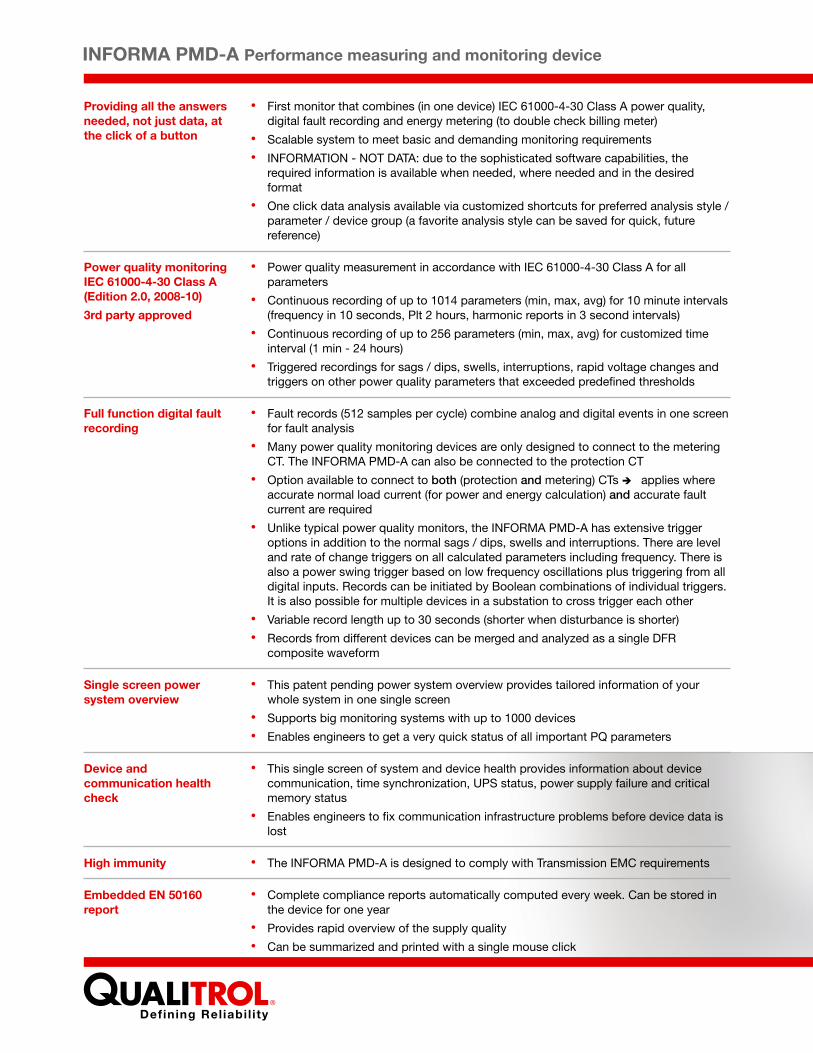
First monitor that combines (in one device) IEC 61000-4-30 Class A power quality, digital fault recording and energy metering (to double check billing meter)
Scalable system to meet basic and demanding monitoring requirements
INFORMATION - NOT DATA: due to the sophisticated software capabilities, the required information is available when needed, where needed and in the desired format
One click data analysis available via customized shortcuts for preferred analysis style / parameter / device group (a favorite analysis style can be saved for quick, future reference)
Power quality measurement in accordance with IEC 61000-4-30 Class A for all parameters
Continuous recording of up to 1014 parameters (min, max, avg) for 10 minute intervals (frequency in 10 seconds, Plt 2 hours, harmonic reports in 3 second intervals)
Continuous recording of up to 256 parameters (min, max, avg) for customized time interval (1 min - 24 hours)
Triggered recordings for sags / dips, swells, interruptions, rapid voltage changes and triggers on other power quality parameters that exceeded predefined thresholds
Fault records (512 samples per cycle) combine analog and digital events in one screen for fault analysis
Many power quality monitoring devices are only designed to connect to the metering CT. The INFORMA PMD-A can also be connected to the protection CT
Option available to connect to both (protection and metering) CTs è applies where accurate normal load current (for power and energy calculation) and accurate fault current are required
Unlike typical power quality monitors, the INFORMA PMD-A has extensive trigger options in addition to the normal sags / dips, swells and interruptions. There are level and rate of change triggers on all calculated parameters including frequency. There is also a power swing trigger based on low frequency oscillations plus triggering from all digital inputs. Records can be initiated by Boolean combinations of individual triggers. It is also possible for multiple devices in a substation to cross trigger each other
Variable record length up to 30 seconds (shorter when disturbance is shorter)
Records from different devices can be merged and analyzed as a single DFR composite waveform
This patent pending power system overview provides tailored information of your whole system in one single screen
Supports big monitoring systems with up to 1000 devices
Enables engineers to get a very quick status of all important PQ parameters
This single screen of system and device health provides information about device communication, time synchronization, UPS status, power supply failure and critical memory status
Enables engineers to fix communication infrastructure problems before device data is lost
The INFORMA PMD-A is designed to comply with Transmission EMC requirements
Complete compliance reports automatically computed every week. Can be stored in the device for one year
Provides rapid overview of the supply quality
Can be summarized and printed with a single mouse click
Full function digital fault recording
Single screen power system overview
Device and communication health check
l
l
l
l
l
l
l
l
l
l
l
l
l
l
l
l
l
l
Standard or user-defined thresholds can be set, e.g, dips defined at -10 % in EN 50160 can be changed to user thresholds of -15 %
Cumulative probability (CP) of 95% as defined in EN 50160 can also be changed (e.g. 99%)
Meeting utilities specific report requirements. Qualitrol’s report writer enables customized reports, the saving of report templates, the creation of automatic reports and notification when critical events happen (via e-mail, text message or mobile phone)
No need to create regulatory or company internal reports manually
Plug and play USB port enabling the simple upload of device data onto a USB memory stick when on-site
Easy data upload in the event that communication infrastructure is out of order
Copy / synchronize the data into the main database
Reduce risk of data loss when communication infrastructure breaks down
Automatic compliance reports in accordance with IEC 61000-3-6 (Assessment of emission limits for distorting loads in MV and HV power systems)
Automatic compliance reports in accordance with IEC 61000-3-7 (Assessment of emission limits for fluctuating loads in MV and HV power systems)
Device configuration can be copied from one device to another
The device commissioning tool is designed to avoid that important parameters are not set
Configuration and commissioning software does not require an installation on a PC, therefore no installation or license is required for the PCs of commissioning personnel
Instruction for commissioning personnel can be done in a few minutes
The default included database is the Microsoft SQL 2005 Express (4 GB)
For larger systems the fully licensed Microsoft SQL is used
The system is designed to work with up to 1000 devices
Capture impulsive transients (mainly caused by lightning) and oscillatory transients (mainly caused by capacitor bank switching) with very high resolution of 20 MHz sampling rate to get additional information to your normal fault record
Embedded user defined report
Customized reporting
Plug and play data backup on-site
USB port for data upload to memory stick
IEC 61000-3-6 and 61000-3-7 reports (Edition 2.0, 2008-02)
Easy commissioning and configuration
Data available where and how you need it
Transient Recording
High immunity
Embedded EN 50160 report

INFORMA PMD-A Performance measuring and monitoring device
www.qualitrolcorp.com
Providing all the answers needed, not just data, at the click of a button
Power quality monitoring IEC 61000-4-30 Class A(Edition 2.0, 2008-10)
3rd party approved
l
l
l
l
l
l
l
l
l
l
l
l
l
l
l
l
l
l
l
l
l
l
l
First monitor that combines (in one device) IEC 61000-4-30 Class A power quality, digital fault recording and energy metering (to double check billing meter)
Scalable system to meet basic and demanding monitoring requirements
INFORMATION - NOT DATA: due to the sophisticated software capabilities, the required information is available when needed, where needed and in the desired format
One click data analysis available via customized shortcuts for preferred analysis style / parameter / device group (a favorite analysis style can be saved for quick, future reference)
Power quality measurement in accordance with IEC 61000-4-30 Class A for all parameters
Continuous recording of up to 1014 parameters (min, max, avg) for 10 minute intervals (frequency in 10 seconds, Plt 2 hours, harmonic reports in 3 second intervals)
Continuous recording of up to 256 parameters (min, max, avg) for customized time interval (1 min - 24 hours)
Triggered recordings for sags / dips, swells, interruptions, rapid voltage changes and triggers on other power quality parameters that exceeded predefined thresholds
Fault records (512 samples per cycle) combine analog and digital events in one screen for fault analysis
Many power quality monitoring devices are only designed to connect to the metering CT. The INFORMA PMD-A can also be connected to the protection CT
Option available to connect to both (protection and metering) CTs è applies where accurate normal load current (for power and energy calculation) and accurate fault current are required
Unlike typical power quality monitors, the INFORMA PMD-A has extensive trigger options in addition to the normal sags / dips, swells and interruptions. There are level and rate of change triggers on all calculated parameters including frequency. There is also a power swing trigger based on low frequency oscillations plus triggering from all digital inputs. Records can be initiated by Boolean combinations of individual triggers. It is also possible for multiple devices in a substation to cross trigger each other
Variable record length up to 30 seconds (shorter when disturbance is shorter)
Records from different devices can be merged and analyzed as a single DFR composite waveform
This patent pending power system overview provides tailored information of your whole system in one single screen
Supports big monitoring systems with up to 1000 devices
Enables engineers to get a very quick status of all important PQ parameters
This single screen of system and device health provides information about device communication, time synchronization, UPS status, power supply failure and critical memory status
Enables engineers to fix communication infrastructure problems before device data is lost
The INFORMA PMD-A is designed to comply with Transmission EMC requirements
Complete compliance reports automatically computed every week. Can be stored in the device for one year
Provides rapid overview of the supply quality
Can be summarized and printed with a single mouse click
Full function digital fault recording
Single screen power system overview
Device and communication health check
l
l
l
l
l
l
l
l
l
l
l
l
l
l
l
l
l
l
Standard or user-defined thresholds can be set, e.g, dips defined at -10 % in EN 50160 can be changed to user thresholds of -15 %
Cumulative probability (CP) of 95% as defined in EN 50160 can also be changed (e.g. 99%)
Meeting utilities specific report requirements. Qualitrol’s report writer enables customized reports, the saving of report templates, the creation of automatic reports and notification when critical events happen (via e-mail, text message or mobile phone)
No need to create regulatory or company internal reports manually
Plug and play USB port enabling the simple upload of device data onto a USB memory stick when on-site
Easy data upload in the event that communication infrastructure is out of order
Copy / synchronize the data into the main database
Reduce risk of data loss when communication infrastructure breaks down
Automatic compliance reports in accordance with IEC 61000-3-6 (Assessment of emission limits for distorting loads in MV and HV power systems)
Automatic compliance reports in accordance with IEC 61000-3-7 (Assessment of emission limits for fluctuating loads in MV and HV power systems)
Device configuration can be copied from one device to another
The device commissioning tool is designed to avoid that important parameters are not set
Configuration and commissioning software does not require an installation on a PC, therefore no installation or license is required for the PCs of commissioning personnel
Instruction for commissioning personnel can be done in a few minutes
The default included database is the Microsoft SQL 2005 Express (4 GB)
For larger systems the fully licensed Microsoft SQL is used
The system is designed to work with up to 1000 devices
Capture impulsive transients (mainly caused by lightning) and oscillatory transients (mainly caused by capacitor bank switching) with very high resolution of 20 MHz sampling rate to get additional information to your normal fault record
Embedded user defined report
Customized reporting
Plug and play data backup on-site
USB port for data upload to memory stick
IEC 61000-3-6 and 61000-3-7 reports (Edition 2.0, 2008-02)
Easy commissioning and configuration
Data available where and how you need it
Transient Recording
High immunity
Embedded EN 50160 report
INFORMA PMD-A Performance measuring and monitoring device
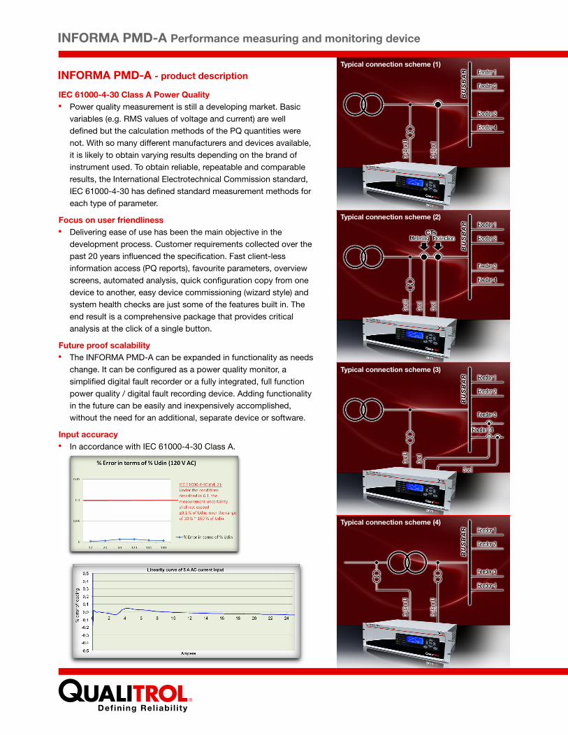
INFORMA PMD-A - product descriptionTypical connection scheme (1)
Typical connection scheme (2)
Typical connection scheme (3)
Typical connection scheme (4)
Processor
TECHNICAL SPECIFICATIONS
Overview
Operating system
www.qualitrolcorp.com
Status indicators
Quality system
Calibration
Data storage
Power supply Input range
Maximum load
32 bit, 400 MHz processor9 configurable analog channels for INFORMA PMD-A 3U device9/18/27/36 configurable analog channels for INFORMA PMD-A 6U deviceSampling rate 25.6 kHz at 50 Hz, 30.72 kHz at 60 HzBandwidth 25 to 4600 Hz ± 0.5 dB
MontaVista Linux with real time extensions
9 LEDs - healthy, communication, clock sync, battery, trigger, alarm and sensors (status)
Developed, designed, and manufactured according to DN ISO 9001:2000
Solid state design, no user adjustmentsCalibration check to be performed once in 5 years
Compact Flash for record storage 4 GB standard (8 GB/16 GB optional) On-board Flash for firmware - 64 MB A RAM based temporary file system is used to avoid excessive Flash use avoiding Flash wear. The INFORMA firmware is designed to optimize the write operations for every memory block.
Type 1: 90 - 264 VAC (88-300 VDC), 47 -63 Hz.Type 2: 36 - 72 VDC.Type 3: 18 - 36 VDC
40 VA for 3U INFORMA PMD-A device and 80 VA for 6U INFORMAPMD-A device
25 VA for 3U INFORMA PMD-A device and 50 VA for 6U INFORMAPMD-A device
DC output 12 VDC at 750 mA
Nominal (full scale) in VAC: 63.5 (140), 120 (270), 240 (480), 440 (800)
300 V CAT III, 150 V CAT IV
1000 VAC continuous
Impedance: > 2.5 M (at 63.5 V), > 2 M (at 120 V), > 1 M (at 240 V),> 0.1 M (at 440 V) 16-bit resolution for voltage. 20-bit resolution for current(To achieve a 20-bit resolution on a current channel, two 16-bit A/D converters are used with different gain factors to provide an effective 20-bit resolution)
Impedance: > 4M24-bit resolution for voltage/current channels.Error 0.1°
The transient voltage (up to 6 kV) is detected by the TR module with a bandwidth of 2.5 kHz to 5 MHz. Sampling rates (user configurable): 20 MHz, 10 MHz, 5 MHz, 2.5 MHz, 1.25 MHz 12-bit resolution
Full scale in VDC: 12, 120, 240, 480
300 V CAT III, 150 V CAT IV
500 VDC continuous
420 K (TX-AFE and HIA-AFE)
Ω Ω Ω Ω
Ω
≤
≥ Ω
Typical load
Auxiliary output
Analog inputs -voltage AC Safety rating
Maximum overload
Input option 1:TX_AFE
Input range
Input option 2:HIA_AFE
Optional forHIA-AFE:Fast Transient Recording
Analog Inputs - Voltage DC(optional -instead of AC)
Input range
Safety rating
Maximum overload
Input impedance
IEC 61000-4-30 Class A Power Qualityl
Focus on user friendlinessl
Future proof scalabilityl
Input accuracyl
Power quality measurement is still a developing market. Basic variables (e.g. RMS values of voltage and current) are well defined but the calculation methods of the PQ quantities were not. With so many different manufacturers and devices available, it is likely to obtain varying results depending on the brand of instrument used. To obtain reliable, repeatable and comparable results, the International Electrotechnical Commission standard, IEC 61000-4-30 has defined standard measurement methods for each type of parameter.
Delivering ease of use has been the main objective in the development process. Customer requirements collected over the past 20 years influenced the specification. Fast client-less information access (PQ reports), favourite parameters, overview screens, automated analysis, quick configuration copy from one device to another, easy device commissioning (wizard style) and system health checks are just some of the features built in. The end result is a comprehensive package that provides critical analysis at the click of a single button.
The INFORMA PMD-A can be expanded in functionality as needs change. It can be configured as a power quality monitor, a simplified digital fault recorder or a fully integrated, full function power quality / digital fault recording device. Adding functionality in the future can be easily and inexpensively accomplished, without the need for an additional, separate device or software.
In accordance with IEC 61000-4-30 Class A.
Processor
TECHNICAL SPECIFICATIONS
Overview
Operating system
Status indicators
Quality system
Calibration
Data storage
Power supply Input range
Maximum load
32 bit, 400 MHz processor9 configurable analog channels for INFORMA PMD-A 3U device9/18/27/36 configurable analog channels for INFORMA PMD-A 6U deviceSampling rate 25.6 kHz at 50 Hz, 30.72 kHz at 60 HzBandwidth 25 to 4600 Hz ± 0.5 dB
MontaVista Linux with real time extensions
9 LEDs - healthy, communication, clock sync, battery, trigger, alarm and sensors (status)
Developed, designed, and manufactured according to DN ISO 9001:2000
Solid state design, no user adjustmentsCalibration check to be performed once in 5 years
Compact Flash for record storage 4 GB standard (8 GB/16 GB optional) On-board Flash for firmware - 64 MB A RAM based temporary file system is used to avoid excessive Flash use avoiding Flash wear. The INFORMA firmware is designed to optimize the write operations for every memory block.
Type 1: 90 - 264 VAC (88-300 VDC), 47 -63 Hz.Type 2: 36 - 72 VDC.Type 3: 18 - 36 VDC
40 VA for 3U INFORMA PMD-A device and 80 VA for 6U INFORMAPMD-A device
25 VA for 3U INFORMA PMD-A device and 50 VA for 6U INFORMAPMD-A device
DC output 12 VDC at 750 mA
Nominal (full scale) in VAC: 63.5 (140), 120 (270), 240 (480), 440 (800)
300 V CAT III, 150 V CAT IV
1000 VAC continuous
Impedance: > 2.5 M (at 63.5 V), > 2 M (at 120 V), > 1 M (at 240 V),> 0.1 M (at 440 V) 16-bit resolution for voltage.
Impedance: > 4M24-bit resolution for voltage/current channels.Error 0.1°
The transient voltage (up to 6 kV) is detected by the TR module with a bandwidth of 2.5 kHz to 5 MHz. Sampling rates (user configurable): 20 MHz, 10 MHz, 5 MHz, 2.5 MHz, 1.25 MHz 12-bit resolution
Full scale in VDC: 12, 120, 240, 480
300 V CAT III, 150 V CAT IV
500 VDC continuous
420 K (TX-AFE and HIA-AFE)
Ω Ω Ω Ω
Ω
≤
≥ Ω
Typical load
Auxiliary output
Analog inputs -voltage AC Safety rating
Maximum overload
Input option 1:TX_AFE
Input range
Input option 2:HIA_AFE
Optional forHIA-AFE:Fast Transient Recording
Analog Inputs - Voltage DC(optional -instead of AC)
Input range
Safety rating
Maximum overload
Input impedance
INFORMA PMD-A Performance measuring and monitoring device
INFORMA PMD-A - product descriptionTypical connection scheme (1)
Typical connection scheme (2)
Typical connection scheme (3)
Typical connection scheme (4)
www.qualitrolcorp.com
IEC 61000-4-30 Class A Power Qualityl
Focus on user friendlinessl
Future proof scalabilityl
Input accuracyl
Power quality measurement is still a developing market. Basic variables (e.g. RMS values of voltage and current) are well defined but the calculation methods of the PQ quantities were not. With so many different manufacturers and devices available, it is likely to obtain varying results depending on the brand of instrument used. To obtain reliable, repeatable and comparable results, the International Electrotechnical Commission standard, IEC 61000-4-30 has defined standard measurement methods for each type of parameter.
Delivering ease of use has been the main objective in the development process. Customer requirements collected over the past 20 years influenced the specification. Fast client-less information access (PQ reports), favourite parameters, overview screens, automated analysis, quick configuration copy from one device to another, easy device commissioning (wizard style) and system health checks are just some of the features built in. The end result is a comprehensive package that provides critical analysis at the click of a single button.
The INFORMA PMD-A can be expanded in functionality as needs change. It can be configured as a power quality monitor, a simplified digital fault recorder or a fully integrated, full function power quality / digital fault recording device. Adding functionality in the future can be easily and inexpensively accomplished, without the need for an additional, separate device or software.
In accordance with IEC 61000-4-30 Class A.
EMC STANDARDS
INFORMA PMD-A Performance measuring and monitoring device
www.qualitrolcorp.com
IEC 60255-22-6 / IEC 61000-4-6Conducted Susceptibility (CS)
Tested to IEC 61000-4-6. Tested for 10 V, 150 kHz - 80 MHzTested on power line, RS232 -1, Ethernet port 1, analog inputs (V and I), digital inputs and relay outputs.Passed with Criteria A
Tested to IEC 61000-4-4. Tested for 4 kV, 5 kHz / 100 kHz / 2.5 kHzTested on power line, RS232-1, Ethernet port 1, analog inputs (V and I), digital inputs and relay outputsPassed with Criteria A
Tested to IEC 61000-4-3. Tested for 10 V/m, 80 MHz - 1000 MHzTested on complete devicePassed with Criteria A
Tested to CISPR-11. Tested for 79 dB (µV) quasi-peak and 66 dB (µV) average at 0.15 MHz to 0.5 MHzTested for 73 dB (µV) quasi-peak and 60 dB (µV) average at 0.50 MHz to 5 MHzTested for 73 dB (µV) quasi-peak and 60 dB (µV) average at 0.50 MHz to 5 MHz Tested on complete devicePassed and the emission levels are within the specified limits of CISPR 11
Tested to CISPR-11. Tested for 40 dB (µV/m) quasi-peak from 30 MHz to 230 MHz at 10 m (32.8 ft)Tested for 47 dB (µV/m) quasi-peak from 230 MHz to 1000 MHz at 10 m (32.8 ft)Tested on complete devicePassed and the emission levels are within the specified limits of CISPR 11
Tested to IEC 61000-4-8. Tested for 30 A/m, x, y, z axis. Tested on complete devicePassed with Criteria A
Tested to IEC 61000-4-12. Tested for 2.5 kV common mode, 1 kV differential mode, 1 MHzTested on power-line, digital, analog inputs (V), relayPassed with Criteria A
Tested to IEC 61000-4-12. Tested for level 3, ±2 kV common mode, 1 kV differential mode, 100KHzTested on power-line, digital, analog inputs (V), relayPassed with Criteria A
Tested to IEC 61000-4-5. Tested for class 4, I/O 4 kV common mode, 2 kV differential mode Tested on power-line, digital, analog inputs (V), relayPassed with Criteria A
Tested to ENV 50204. Tested for level 3, 10 V/m, at 900 MHz ± 5 MHz, at 1890 MHz ± 10 MHz keyed at frequency 200 Hz ± 1%, 50% duty cycle (2.5 ms ON 2.5 ms OFF). Tested on complete devicePassed with Criteria A
Tested to 2.5kV for 1 minute. Tested for 2 kV for power port, analog inputs (V and I), digital inputs, relay and 1 kV for isolated communication ports (RS232 and RS485)No flashover or breakdown occurred
Tested to applied 500 VDC with respect to earth. Tested on power port, analog inputs (V and I), digital inputs and relay. The impedance was greater than 100 M
Tested to ±5 kV, 0.5 J. Tested on power-line, digital, analog inputs (V and I) and relayNo flashover or breakdown occurred
Tested to dips - Class-3, interruptions - Class-3. Tested on Power-port.Passed with dips - Criteria A, interruptions - Criteria B
Tested to IEC 61000-4-2. Tested for 8 kV contact, 15 kV airTested on enclosure, all accessible I/O lines and portsPassed with Criteria A
Tested for PSUTested for DC range 80 VDC to 132 VDC
Tested for cold storage -45ºC (49ºF) for 96 hours. Cold operating -5ºC (23ºF) for 16 hoursTested on complete device
Tested for 2g acceleration, frequency is 10 - 150 HZ, 20 sweep cycles in each of three mutually perpendicular planes (x, y, and z). Tested on complete device
Tested for cyclic temperature test for 5 cyclesEach cycle has 3 hours for 70 degrees and 3 hours for -5 degree in power off conditionTested on complete device
Mechanical shocks of 0.5 J
Peak acceleration value: 10 ms - 2. Duration of the pulse: 16 msNumber of jolts: 1000 ± 10. Rate: 3 jolts per second
Harmonics and inter harmonics
Ω
IEC 60255-22-4 / IEC 61000-4-4and ANSI C37.90.1.2002Electrical fast transient burst test
IEC 60255-22-3 / IEC 61000-4-3Radiated Susceptibility (RS)
EN 55011 Conducted Emission (CE)
EN 55011 Radiated Emission (CE)
IEC 61000-4-8 Power frequencymagnetic field test
IEC 60255-22-1 / IEC 61000-4-12and ANSI C37.90.1.2002 Dampedoscillatory wave disturbance tests
IEC 61000-4-12 Ring wave test
IEC 61000-4-5 Surge test
ENV 50204 Immunity to EMIfrom digital radio telephones
IEC 60255-5 Clause 6 Dielectric testANSI IEEE C37.90 - 1989SWC dielectric tests
IEC 60255-5 Clause 7 Insulation test
IEC 60255-5 Clause 8Impulse voltage test
IEC 61000-4-11 Supply voltage dipsand interruptions
IEC 60255-22-2 / IEC 61000-4-2Electro static discharge tests
IEC 60255-6 / EN60255-6Supply voltage limit test
IEC 60068-2-1 / EN60068-2-1Cold tests
IEC 60068-2-6 Vibration tests
IEC 60068-2 Cyclic temperature test
BS EN 62262:2002Spring hammer test
BS EN 60068-2-29 Bump test
IEC 61000-4-13 Testing andmeasurement techniques
TECHNICAL SPECIFICATIONS
Input impedance
Nominal (full scale) in AAC: 1 (10), 2 (20), 5 (50), 10 (100)
200 A for 1 second, 40 A continuous
< 0.02 20-bit resolution for current(To achieve a 20-bit resolution on a current channel two 16-bit A/D converters are used with different gain factors to provide an effective 20-bit resolution.)
32 (isolated into groups of 8)Voltage range independent from 24/48 to 250 VDC
4 form A/B relay outputs (configurable - normally closed or normally open at factory)
Relay 1 indicates system healthyRelays 2 and 3 are user configurable for PQ parametersRelay 4 is user configurable for either temperature under/over temperature thresholdResistive load: 250 VAC 5 A, 110 VDC 0.5 A, 48 VDC 1.0 A
GPS (accuracy ± 300 ns between time masters)IRIG-B modulated and level shift (accuracy ± 2 ms between time masters)Time slave (synchronized through 1 PPS)
H x W x D: 132.5 mm [5.2’] x 487 mm [19.2’] x 362.2 mm [14.3’]
H x W x D: 265.8 mm [10.5’] 487 mm [19.2’] x 362.2 mm [14.3’]
15 kg [33.1 lbs] without battery and 15.5 kg [34.2 lbs] with battery
23 kg [50.1 lbs] without any external battery and 24 kg [52.9 lbs] with two external batteries
Metal 19” rack mountable enclosure
Four serial ports (of these, three are RS232 ports with male DB-9 connectors, and one is RS485 with 1*5 pin connector)Internal PSTN (V.90) modem (optional on RS232-2)Two 100 Mb Ethernet ports with RJ45 connectorsOptional fiber optic Ethernet (on rear port)Differential (RS485 levels) for 1 PPS for time synchronizationFiber optic 1 PPS output (master) / input (slave)
TCP/IP, Modbus, IEC 60870-5, IEC 61850, GSM, GPRS
IEC 61000-4-30 Class AIEC 61000-4-7 harmonics and inter-harmonicsIEC 61000-4-15 flickerCBEMA, ITICIEEE 1159, IEEE 519
Operating: -5°C to 50°C (23°F to 122°F)Cold start is not possible below 0°C (32°F)Storage: -30°C to +70°C (-22°F to +158°F)
0 to 95% non-condensing
IP 41 according to IEC 60529
RoHS compliant
Ω.
Digital inputs
Alarm notification
Maximum overload
Time synchronization
Dimensions - 3U device
Dimensions - 6U device
Weight - 3U device
Weight - 3U device
Housing/mounting
Temperature
Input rangeAnalog inputs -current
Options
Mechanical
Communication Ports
Protocols
Standardcompliance
Environmental
Humidity
Enclosure
Others

INFORMA PMD-A Performance measuring and monitoring device
www.qualitrolcorp.com
TECHNICAL SPECIFICATIONS
Input impedance
Nominal (full scale) in AAC: 1 (10), 2 (20), 5 (50), 10 (100)
200 A for 1 second, 40 A continuous
< 0.02 20-bit resolution for current(To achieve a 20-bit resolution on a current channel two 16-bit A/D converters are used with different gain factors to provide an effective 20-bit resolution.)
32 (isolated into groups of 8)Voltage range independent from 24/48 to 250 VDC
4 form A/B relay outputs (configurable - normally closed or normally open at factory)
Relay 1 indicates system healthyRelays 2 and 3 are user configurable for PQ parametersRelay 4 is user configurable for either temperature under/over temperature thresholdResistive load: 250 VAC 5 A, 110 VDC 0.5 A, 48 VDC 1.0 A
GPS (accuracy ± 300 ns between time masters)IRIG-B modulated and level shift (accuracy ± 2 ms between time masters)Time slave (synchronized through 1 PPS)
H x W x D: 132.5 mm [5.2’] x 487 mm [19.2’] x 362.2 mm [14.3’]
H x W x D: 265.8 mm [10.5’] 487 mm [19.2’] x 362.2 mm [14.3’]
15 kg [33.1 lbs] without battery and 15.5 kg [34.2 lbs] with battery
23 kg [50.1 lbs] without any external battery and 24 kg [52.9 lbs] with two external batteries
Metal 19” rack mountable enclosure
Four serial ports (of these, three are RS232 ports with male DB-9 connectors, and one is RS485 with 1*5 pin connector)Internal PSTN (V.90) modem (optional on RS232-2)Two 100 Mb Ethernet ports with RJ45 connectorsOptional fiber optic Ethernet (on rear port)Differential (RS485 levels) for 1 PPS for time synchronizationFiber optic 1 PPS output (master) / input (slave)
TCP/IP, Modbus, IEC 60870-5, IEC 61850, GSM, GPRS
IEC 61000-4-30 Class AIEC 61000-4-7 harmonics and inter-harmonicsIEC 61000-4-15 flickerCBEMA, ITICIEEE 1159, IEEE 519
Operating: -5°C to 50°C (23°F to 122°F)Cold start is not possible below 0°C (32°F)Storage: -30°C to +70°C (-22°F to +158°F)
0 to 95% non-condensing
IP 41 according to IEC 60529
RoHS compliant
Ω.
Digital inputs
Alarm notification
Maximum overload
Time synchronization
Dimensions - 3U device
Dimensions - 6U device
Weight - 3U device
Weight - 3U device
Housing/mounting
Temperature
Input rangeAnalog inputs -current
Options
Mechanical
Communication Ports
Protocols
Standardcompliance
Environmental
Humidity
Enclosure
Others
EMC STANDARDS
IEC 60255-22-6 / IEC 61000-4-6Conducted Susceptibility (CS)
Tested to IEC 61000-4-6. Tested for 10 V, 150 kHz - 80 MHzTested on power line, RS232 -1, Ethernet port 1, analog inputs (V and I), digital inputs and relay outputs.Passed with Criteria A
Tested to IEC 61000-4-4. Tested for 4 kV, 5 kHz / 100 kHz / 2.5 kHzTested on power line, RS232-1, Ethernet port 1, analog inputs (V and I), digital inputs and relay outputsPassed with Criteria A
Tested to IEC 61000-4-3. Tested for 10 V/m, 80 MHz - 1000 MHzTested on complete device. Passed with Criteria A
Tested to CISPR-11. Tested for 79 dB (µV) quasi-peak and 66 dB (µV) average at 0.15 MHz to 0.5 MHzTested for 73 dB (µV) quasi-peak and 60 dB (µV) average at 0.50 MHz to 5 MHzTested for 73 dB (µV) quasi-peak and 60 dB (µV) average at 0.50 MHz to 5 MHz Tested on complete device. Passed and the emission levels are within the specified limits of CISPR 11
Tested to CISPR-11. Tested for 40 dB (µV/m) quasi-peak from 30 MHz to 230 MHz at 10 m (32.8 ft)Tested for 47 dB (µV/m) quasi-peak from 230 MHz to 1000 MHz at 10 m (32.8 ft)Tested on complete device. Passed and the emission levels are within the specified limits of CISPR 11
Tested to IEC 61000-4-8. Tested for 30 A/m, x, y, z axis. Tested on complete devicePassed with Criteria A
Tested to IEC 61000-4-12. Tested for 2.5 kV common mode, 1 kV differential mode, 1 MHzTested on power-line, digital, analog inputs (V), relay. Passed with Criteria A
Tested to IEC 61000-4-12. Tested for level 3, ±2 kV common mode, 1 kV differential mode, 100KHzTested on power-line, digital, analog inputs (V), relay. Passed with Criteria A
Tested to IEC 61000-4-5. Tested for class 4, I/O 4 kV common mode, 2 kV differential mode Tested on power-line, digital, analog inputs (V), relay. Passed with Criteria A
Tested to ENV 50204. Tested for level 3, 10 V/m, at 900 MHz ± 5 MHz, at 1890 MHz ± 10 MHz keyed at frequency 200 Hz ± 1%, 50% duty cycle (2.5 ms ON 2.5 ms OFF). Tested on complete devicePassed with Criteria A
Tested to 2.5kV for 1 minute. Tested for 2 kV for power port, analog inputs (V and I), digital inputs, relay and 1 kV for isolated communication ports (RS232 and RS485)No flashover or breakdown occurred
Tested to applied 500 VDC with respect to earth. Tested on power port, analog inputs (V and I), digital inputs and relay. The impedance was greater than 100 M
Tested to ±5 kV, 0.5 J. Tested on power-line, digital, analog inputs (V and I) and relayNo flashover or breakdown occurred
Tested to dips - Class-3, interruptions - Class-3. Tested on Power-port.Passed with dips - Criteria A, interruptions - Criteria B
Tested to IEC 61000-4-2. Tested for 8 kV contact, 15 kV airTested on enclosure, all accessible I/O lines and ports. Passed with Criteria A
Tested for PSU. Tested for DC range 80 VDC to 132 VDC
Tested for cold storage -45ºC (-49ºF) for 96 hours. Cold operating -5ºC (23ºF) for 16 hoursTested on complete device
Tested for 2g acceleration, frequency is 10 - 150 HZ, 20 sweep cycles in each of three mutually perpendicular planes (x, y, and z). Tested on complete device
Tested for cyclic temperature test for 5 cyclesEach cycle has 3 hours for 70 degrees and 3 hours for -5 degree in power off conditionTested on complete device
Mechanical shocks of 0.5 J
Peak acceleration value: 10 ms - 2. Duration of the pulse: 16 msNumber of jolts: 1000 ± 10. Rate: 3 jolts per second
Harmonics and inter harmonics
Dry heat storage: 70ºC (158ºF) for 4 days (96 hours), humidity 0 - 95 % non-condensingDry heat operating: 45ºC (113ºF) for 16 hours, humidity 0 - 95 % non-condensing
Safety requirements for electrical equipment for measurement, control and laboratory use
Provides general recommendations concerning the choice of relevant tests
Ω
IEC 60255-22-4 / IEC 61000-4-4and ANSI C37.90.1.2002Electrical fast transient burst test
IEC 60255-22-3 / IEC 61000-4-3Radiated Susceptibility (RS)
EN 55011 Conducted Emission (CE)
EN 55011 Radiated Emission (CE)
IEC 61000-4-8 Power frequencymagnetic field test
IEC 60255-22-1 / IEC 61000-4-12and ANSI C37.90.1.2002 Dampedoscillatory wave disturbance tests
IEC 61000-4-12 Ring wave test
IEC 61000-4-5 Surge test
ENV 50204 Immunity to EMIfrom digital radio telephones
IEC 60255-5 Clause 6 Dielectric testANSI IEEE C37.90 - 1989SWC dielectric tests
IEC 60255-5 Clause 7 Insulation test
IEC 60255-5 Clause 8Impulse voltage test
IEC 61000-4-11 Supply voltage dipsand interruptions
IEC 60255-22-2 / IEC 61000-4-2Electro static discharge tests
IEC 60255-6 / EN60255-6Supply voltage limit test
IEC 60068-2-1 / EN60068-2-1Cold tests
IEC 60068-2-6 Vibration tests
IEC 60068-2 Cyclic temperature test
BS EN 62262:2002Spring hammer test
BS EN 60068-2-29 Bump test
IEC 61000-4-13 Testing andmeasurement techniques
IEC 68068-2-2
IEC 61010-1
IEC 61000-4

INFORMA PMD-A
l
l
l
l
Power quality monitoring - IEC 61000-4-30 Class A (Edition 2.0)
Digital fault recording
Single screen power system overview
Device and communication health check
Email: info qualitrolcorp.com@
www.qualitrolcorp.com
®©2010 QUALITROL Company LLC, an ISO 9001 system certified company. All rights reserved. Information subject to change without notice.All trademarks are properties of their respective companies, as noted herein. IP-Q24-05L-01E.
About ®QUALITROL®QUALITROL
manufacturing companies. It is the global leader in sales and installations of transformer asset protection equipment, ®fault recorders and fault locators. Established in 1945, QUALITROL produces thousands of different types of products
on demand, each customized to customers’ unique requirements.
manufactures substation and transformer monitoring and protection devices used by electric utilities and
Product Summary
Performance measuring and monitoring device
Providing all the answers needed,not just data, at the click of a button
Product Summary
®QUALITROL Field Services®QUALITROL provides on-site commissioning/start-up and comprehensive maintenance contracts to all customers
worldwide. To further improve reliability, an extended warranty is available on selected products commissioned by ®QUALITROL .®QUALITROL Educational Services
®QUALITROL professional training (designed to achieve hands-on performance based objectives) prepares operations, ®maintenance, and engineering personnel to install, test, configure, operate and maintain QUALITROL products.
®QUALITROL Accelerated Delivery®QUALITROL provides accelerated delivery on many products and services including replacements, spare parts and
repairs.
INFORMA PMD-A Performance measuring and monitoring device
Description
Application
Single performance measuring and
monitoring device with multi-functional
capabilities including Class A power quality and
fault recording. 9 (optional: 18/27/36) analog
channels available as AC or DC. Eliminates 90%
analytical time, very easy to use. Flexible,
scalable architecture enables users to acquire
only one function at a time adding other
functions later
Distribution substation monitoring