Embed Size (px)
Citation preview

PROVEN 2.5/TM650
FOUNDATION
INSTRUCTIONS
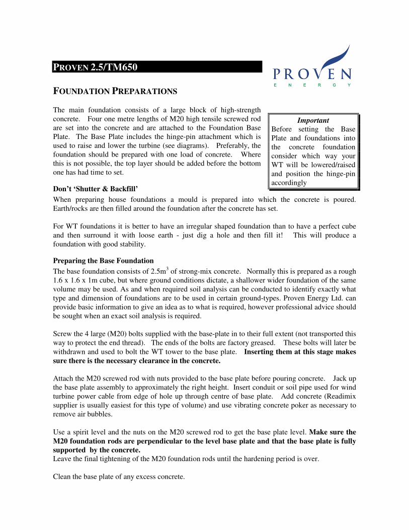
Foundation Pack for Proven 2.5/TM650
PACKING LIST
LIST OF PARTS TO BE SENT WITH BASE PLATE
1 - GALVANISED BASE PLATE
4 – M20 HIGH TENSILE FOUNDATION RODS,
8 – M20 HIGH TENSILE BZP NUTS
4 – M20 BZP WASHERS
4 - M20 x 60 HIGH TENSILE BZP BOLTS AND 4 WASHERS
1 – M30 HIGH TENSILE ANCHOR ROD
1 – ANCHOR PLATE WITH M30 NUT AND WASHER
1 set Foundation Pack
- 1 Pack Description (this page)
- 1 Standard foundation diagram
- 1 Anchor foundation diagram
- 1 Alignment/Access diagram
- 1 Foundation description (incl. concrete mixing details)
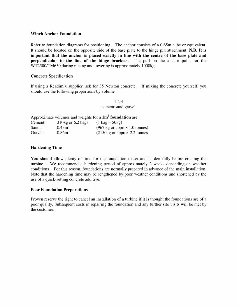
PROVEN 2.5/TM650
FOUNDATION PREPARATIONS
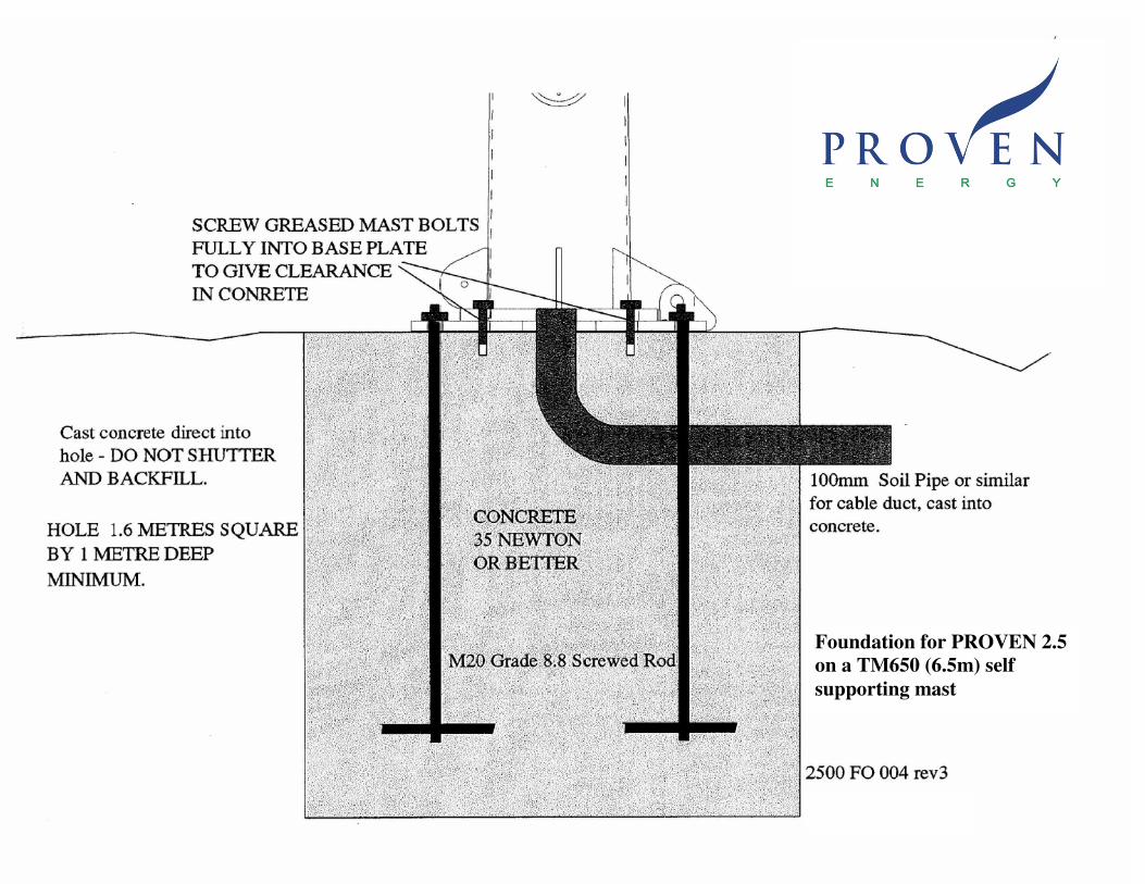
The main foundation consists of a large block of high-strength
concrete. Four one metre lengths of M20 high tensile screwed rod
are set into the concrete and are attached to the Foundation Base
Plate. The Base Plate includes the hinge-pin attachment which is
used to raise and lower the turbine (see diagrams). Preferably, the
foundation should be prepared with one load of concrete. Where
this is not possible, the top layer should be added before the bottom
one has had time to set.
Don’t ‘Shutter & Backfill’
When preparing house foundations a mould is prepared into which the concrete is poured.
Earth/rocks are then filled around the foundation after the concrete has set.
For WT foundations it is better to have an irregular shaped foundation than to have a perfect cube
and then surround it with loose earth - just dig a hole and then fill it! This will produce a
foundation with good stability.
Preparing the Base Foundation
The base foundation consists of 2.5m3 of strong-mix concrete. Normally this is prepared as a rough
1.6 x 1.6 x 1m cube, but where ground conditions dictate, a shallower wider foundation of the same
volume may be used. As and when required soil analysis can be conducted to identify exactly what
type and dimension of foundations are to be used in certain ground-types. Proven Energy Ltd. can
provide basic information to give an idea as to what is required, however professional advice should
be sought when an exact soil analysis is required.
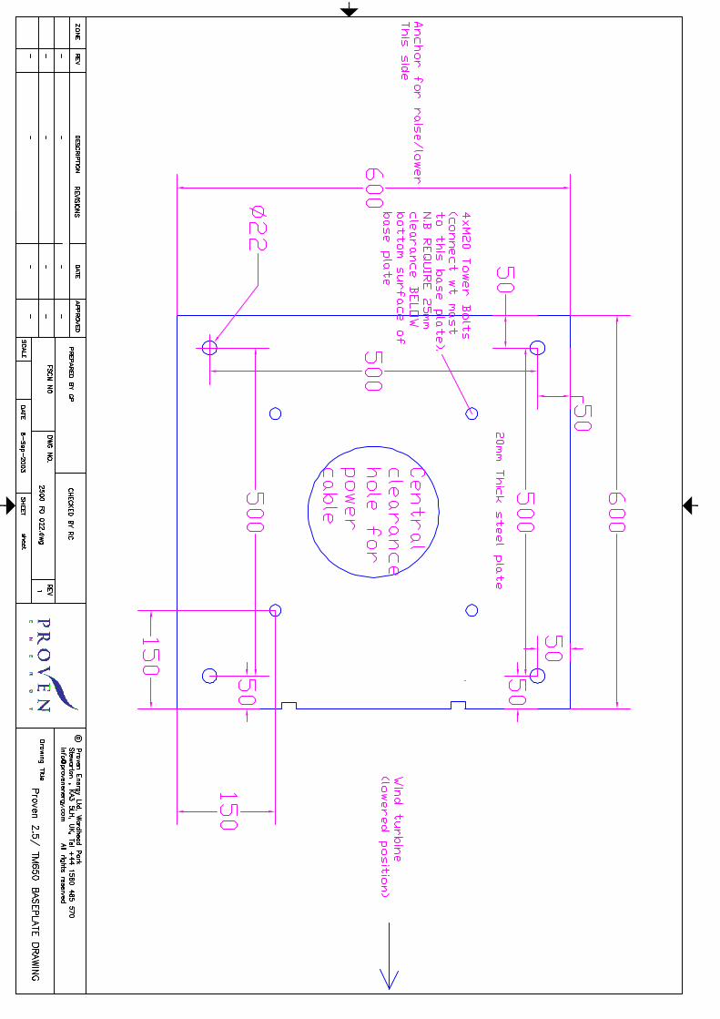
Screw the 4 large (M20) bolts supplied with the base-plate in to their full extent (not transported this
way to protect the end thread). The ends of the bolts are factory greased. These bolts will later be
withdrawn and used to bolt the WT tower to the base plate. Inserting them at this stage makes
sure there is the necessary clearance in the concrete.
Attach the M20 screwed rod with nuts provided to the base plate before pouring concrete. Jack up
the base plate assembly to approximately the right height. Insert conduit or soil pipe used for wind
turbine power cable from edge of hole up through centre of base plate. Add concrete (Readimix
supplier is usually easiest for this type of volume) and use vibrating concrete poker as necessary to
remove air bubbles.
Use a spirit level and the nuts on the M20 screwed rod to get the base plate level. Make sure the
M20 foundation rods are perpendicular to the level base plate and that the base plate is fully
supported by the concrete.
Leave the final tightening of the M20 foundation rods until the hardening period is over.
Clean the base plate of any excess concrete.
Important
Before setting the Base
Plate and foundations into
the concrete foundation
consider which way your
WT will be lowered/raised
and position the hinge-pin
accordingly
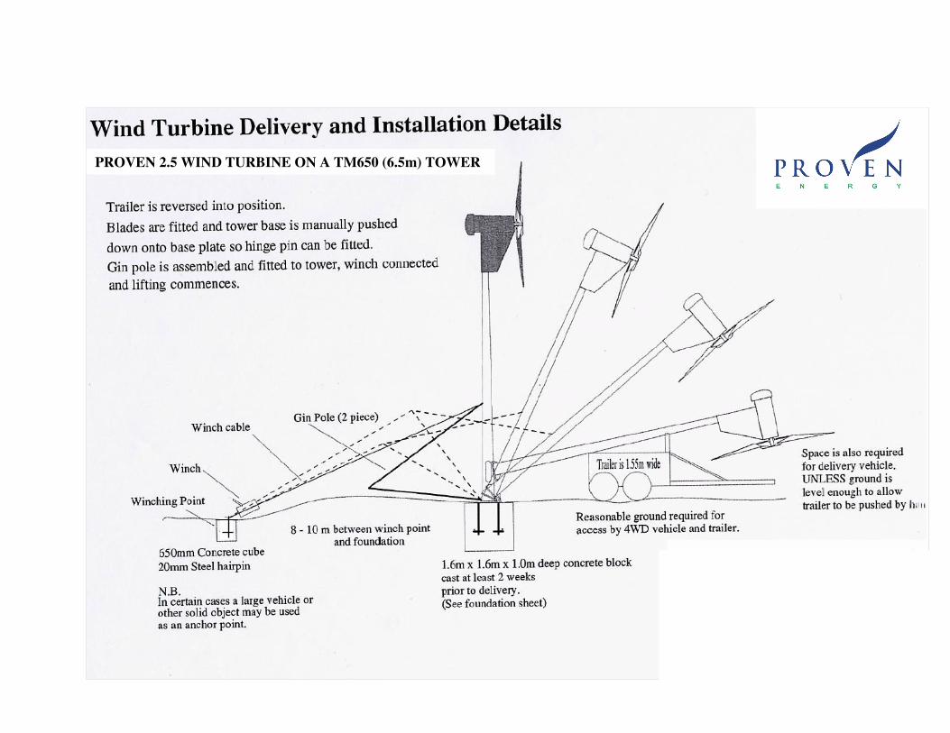
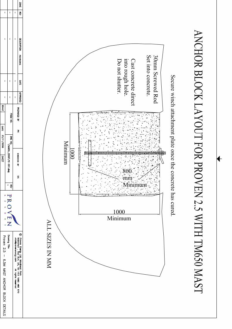
Winch Anchor Foundation
Refer to foundation diagrams for positioning. The anchor consists of a 0.65m cube or equivalent.
It should be located on the opposite side of the base plate to the hinge pin attachment. N.B. It is
important that the anchor is placed exactly in line with the centre of the base plate and
perpendicular to the line of the hinge brackets. The pull on the anchor point for the
WT2500/TM650 during raising and lowering is approximately 1000kg.
Concrete Specification
If using a Readimix supplier, ask for 35 Newton concrete. If mixing the concrete yourself, you
should use the following proportions by volume
1:2:4
cement:sand:gravel
Approximate volumes and weights for a 1m3 foundation are
Cement: 310kg or 6.2 bags (1 bag = 50kg)
Sand: 0.43m3 (967 kg or approx 1.0 tonnes)
Gravel: 0.86m3 (2150kg or approx 2.2 tonnes
Hardening Time
You should allow plenty of time for the foundation to set and harden fully before erecting the
turbine. We recommend a hardening period of approximately 2 weeks depending on weather
conditions. For this reason, foundations are normally prepared in advance of the main installation.
Note that the hardening time may be lengthened by poor weather conditions and shortened by the
use of a quick-setting concrete additive.
Poor Foundation Preparations
Proven reserve the right to cancel an installation of a turbine if it is thought the foundations are of a
poor quality. Subsequent costs in repairing the foundation and any further site visits will be met by
the customer.
PROVEN 2.5 WIND TURBINE ON A TM650 (6.5m) TOWER
Foundation for PROVEN 2.5
on a TM650 (6.5m) self
supporting mast
Proven Energy Ltd, Wardhead Park, Stewarton, KA3 5LH, Scotland, UK
Tel: +44(0) 1560 485 570 Fax: +44(0) 1560 485 580 Web: www.provenenergy.com Email: [email protected]
Reg. in Scotland No. 71400
Dear Sir/Madam,
PROVEN CUSTOMER FOUNDATION CONFIRMATION
Please read the following statement. On completion of your foundation work please sign
the statement and return to Proven Energy Ltd, at the above below.
I CERTIFY THAT THE FOUNDATIONS FOR THE WIND TURBINE AND TOWER
(TO BE INSTALLED AT THE ADDRESS BELOW) ARE COMPLETED AS PER
PROVEN INSTRUCTIONS*. I UNDERSTAND THAT I MAY BE CHARGED FOR
ADDITIONAL INSTALLATION WORK IF REQUIRED DUE TO ANY DEVIATION
FROM THE PROVEN SPECIFICATION**.
SIGNED: .………………………………………………….
DATE: ……………………………………………………..
NAME (CAPITALS): ……………………………………...
SITE ADDRESS: …………………………………………..
………………………………………………………………
……………………………………………………………….
* Foundation specification for each wind turbine model is available from Proven Energy
Ltd. Please check that you have the current Proven Foundation Pack for your particular
wind turbine and tower combination.
** e.g. lack of anchor block, wrong hinge orientation etc.
N.B. This form need only be completed and returned if your system is being installed
by Proven Engineers. If your system is being installed by others e.g. Proven
Authorised Distributor, consult them directly regarding foundation requirements.