Embed Size (px)
Citation preview

Thermo-mechanical coupling around pipelinesSeabed pipelines containing hot fluid can heat the surrounding soil, leading to a potentially hazardous increase in excess pore pressure. Dave White collaborated with Byron Byrne and Richard Sandford of Oxford University, to study thermo-mechanical coupling around hot seabed pipelines (Figure 76). Tests were undertaken by Richard in the Oxford University laboratories to examine the interaction between seabed friction and pipeline temperature. This work was supported by the SAFEBUCK Joint Industry Project.
Figure 76: A hot slippery pipeline in the Oxford laboratory (image courtesy of Byron Byrne)
Offshore foundation systemsThe objectives of the Offshore Foundation Systems Research Stream are to develop conceptual models for the calculation of foundation performance, accounting for the specificity of offshore environmental loading, and to encapsulate these models into unified design methods.
Over the last year, a significant body of work relating to issues associated with spudcan foundations has been undertaken. This notably includes physical and numerical investigations of spudcan penetration into multi-layered soils and potential punch through failure, consolidating COFS established expertise into new recommendations and design methods.
COFS has also been accompanying the industry into the development of subsea structures, pioneering new foundation concepts such as the hybrid foundation and new design methods based on yield envelopes associating vertical, horizontal, moment and torsional loadings.
Anchoring systems remains a strong focus for COFS and will see some renewed interests in the near future with the development of foundation solutions for offshore renewable energy devices.
SpudcanDevelopment of an integrated jack-up installation systemIn assessing penetration resistance of spudcan foundations in stratified soils, different design approaches are used for different soil profiles, whether a layer is underlain by a stronger or a weaker layer – sand, clay or silt. PhD student Stefanus Safinus is progressing further in the development of a universal design approach. This approach is applicable to any soil profile, accounting for methodical consistency and robustness. A high quality field and experimental database of spudcan behaviour in layered soils is being consolidated. Spudcan penetration data has been collected from recent centrifuge tests on single, double, and multi-layered soil profiles. Another test series in combination with PIV method is planned to gather visual data of the penetration response.
Carbonate soils prevalent in Australian waters are of particular interest, as the behaviour of spudcan foundations in these soils still poorly understood. Characterisation of these materials is of prime importance to provide input into centrifuge and numerical modelling. Preliminary laboratory tests, including Rowe cell, Triaxial, and Simple Shear tests to identify soil strength behaviour, have been undertaken since August 2011. A VB-Excel program has been coded to assist the interpretation of soil layering from CPT
The University of Western Australia | 87

data, extraction of relevant soil parameters, prediction of spudcan penetration profile and identification of potential punch-though. Preliminary validation against some field and centrifuge data shows promising results (see 77), though more validation against fresh data and refinement will improve our ability to capture failure mechanisms and prediction accuracy. The goal is to develop an integrated jack-up installation system (see 78), which will allow for carrying out cone penetration test (CPT) and real time prediction of spudcan penetration profile prior to preloading. This will assist jack-up operators in making decisions on what measures should be taken during an offshore
Figure 78: CPTu integrated with a spudcan
Figure 77: Prediction of spudcan penetration response from piezocone (CPTu) data
Figure 79: Typical deformed soil and sand plug comparisons for two sets of centrifuge test
installation to prevent or mitigate a potential geotechnical hazard. This project is undertaken with the industry partner Keppel Offshore and Marine, Singapore under the ARC Linkage Project LP110100174.
Spudcan penetration in sand overlaying clayPan Hu, Dong Wang, Sam Stanier and Mark Cassidy continued their research on the ‘punch-through’ problem during spudcan penetration into sand overlying clay. Both potential for ‘punch-through’ and ‘rapid leg run’ observed from spudcan penetration into medium loose sand.
Centrifuge tests were replicated with CEL approach. Typical deformed sand and clay layers at spudcan penetration depth of 20 m were presented in Figure 79 with post-testing soil samples. The sand plug height is critical in assessing the penetration resistance when spudcan and sand plug penetrate into clay. The heights of the cylindrically shaped sand plug from the numerical simulations fit reasonably well with the post-test measurement.
88 | cofs.uwa.edu.au

0
0.5
1
1.5
2
2.5
3
3.5
0 200 400 600
Nor
mal
ised
pen
etra
tion
dept
h d/
D
Vertical bearing capacity, qu( kPa)
Ht/D =0.5, 1, 1.5
Ht/D = ∞
qumax
Figure 80: Load-penetration profiles from Tests Group 2
Spudcan penetration into layered soil profilesIn the offshore oil and gas industry, when multi-layered soils are encountered, foundation bearing capacity predictions need to consider layered soil profiles. For Wen Gao’s PhD studies, large deformation finite element (LDFE) analyses have been conducted to simulate continuous spudcan penetration into three-layer soil. The numerical simulations were carried out using the Remeshing and Interpolating Technique with Small Strain (RITSS) model, illustrated in Figure 80. The effect of a stiff soil layer sandwiched between two soft claylayers on spudcan penetration responses was studied. The soil flow mechanisms at various penetration depths are presented in Figure 81. A particular focus has been to distinguish between true punch through conditions, and conditions where the resistance is simply dependent on an averaging of the nearby soil strength. A rational new design approach to estimate the bearing capacity of spudcans penetrating into multi-layered soil is emerging.
H
H
Ht/D=1, d/D=
Ht/D=1, d/D=
=0.5
=1.7 Ht/D
Ht/D
/D=1, d/D=2.
D=1, d/D=1.2
1 Ht/D
25
D=1, d/D=3
Figure 81: Soil flow mechanism for Group 2, Ht/D=1
The University of Western Australia | 89

Spudcan penetration through multi-layer soilsShazzad Hossain, Stefanus Safinus and Mark Randolph are continuing explorations on spudcan foundations on complex seabed soil conditions with highly layered strata. Their work is expanding from full clay profiles to multi-layer soils with interbedded silica and carbonate sand layers. Shazzad has carried out a suit of centrifuge model tests to investigate the effect of soil type (and hence drainage conditions,) and stress level in the critical strong layer on the likelihood of punch-through. The experimental results show that the failure was less severe for a carbonate sand layer sandwiched by a soft clay layer compared to that for a silica sand layer (see 82), in spite of the higher critical state friction angle of the carbonate sand. This is due to the high compressibility of ‘problematic’ carbonate sand and more severe for an interbedded sand layer compared to that for a surface layer, in spite of identical thickness ratio and similar bottom layer clay strength, due to the fact that a foundation behaviour in sand is highly dependent on the stress level.
Penetration of spudcan foundations into offshore multi-layered soilsThe research work in Neyemat Ullah’s PhD is investigating the load-penetration behaviour of spudcan foundations in layered soils and identifying the penetration mechanisms with consequent load-penetration profiles. Until now, critical questions regarding the boundary effects in small centrifuge strong boxes have been addressed through LDFE (Large Deformation Finite Element) analysis (Figure 83). Knowing the boundary effect, these centrifuge tests were planned and executed successfully on clay-sand-clay soil profile for both spudcan and flat base foundation. High resolution digital images were captured during these tests through a transparent window and were analysed using the PIV (Particle Image Velocimetry) technique (Figure 84). Detailed experimental work in the centrifuge is planned in the future involving complex layered seabed conditions. The work is expected to finish early 2015.
Figure 83: Entrapped sand plug hitting the bottom boundary of the centrifuge strong box
Figure 84: PIV analysis on multi-layer soil
Figure 82: Effect of interbedded strong layer soil type on critical soil failure patterns
(a) Velocity contours
(b) Images
90 | cofs.uwa.edu.au

Set-up and resulting punch-through risk of jack-up spudcans in carbonate silty soilStoppages during spudcan installation occur frequently causing consolidation in the soil surrounding the spudcan. Upon further loading, this may lead to punch-through failure (or at least heightened heart rates in the rig move personnel, as it is not currently possible to reliably assess the punch-through risk).
Though ultimately aimed at carbonate silty soils, this project commenced with centrifuge experiments on the “simpler”, well understood kaolin clay often used in our testing. Some of the results were shared in last year’s Annual Report (a journal paper is under review). In 2012, in the lead-up further centrifuge tests, visitor Joseph Newhouse helped Britta Bienen and Mark Cassidy with some laboratory tests on the offshore carbonate silt that will be used for the remainder of the project.
Concurrently, numerical modelling of the problem was further pursued in collaboration with Majid Nazem of Newcastle University, using SNAC, and Dong Wang, using Abaqus with RITSS. The analyses are extremely challenging as they require accommodation of large deformations and coupled pore pressure-stress response.
Figure 85: Model spudcan featuring jetting system
Extraction of deeply embedded spudcanPhD student Omid Kohan has continued his investigation of the extraction of deeply embedded spudcans. A 40 mm diameter model spudcan was instrumented with two pore pressure transducers (one at the top face and one at the base) and three sets of jetting nozzles (two at the top face and one at the base) each arranged in concentric circles. These sets can be switched on and off, allowing top and bottom jetting configurations to be modelled. Each set of nozzles is inter-connected via a ring channel with a diameter of 1.5 mm. The internal pipes are 2 mm in diameter and are connected to the inlet located at the top of the leg. The nozzles feature an M1.2 mm thread into which a M1.2 mm screw can be inserted to block the flow. Then, a 0.5 mm diameter hole was drilled into each screw to allow water jets. Details of the model geometry are presented in the photo of the model in Figure 85.
The efficiency of water jetting was studied for extraction from depths of up to three diameters in normally consolidated clay, for different jetting flow rates. The excess pore pressure and maximum breakout force measured reveal insights into the extraction process with top and bottom jetting. The maximum extraction resistance is shown to be unaffected by top jetting, but relates to the suction developed at the spudcan base, which can be reduced by jetting at the spudcan base. Top jetting can, however, reduce the extraction resistance post breakout as indicated by the experimental results of this study.
The University of Western Australia | 91

The Dynamically Embedded Plate Anchor (DEPLA): An experimental studyAnthony Blake transferred from the Institute of Technology Sligo, Ireland to COFS in May 2012, to continue his PhD. Anthony has undertaken an experimental study to assess the geotechnical performance of Dynamically Embedded Plate Anchors (DEPLAs). The DEPLA (Figure 88) is a new dynamically installed anchor concept that combines the capacity advantages of vertical loaded anchors with the installation benefits of dynamically installed anchors. After release from 50 to 100 m above the seabed, the DEPLA impacts the seabed with impact velocities of up to 30 m/s and embeds within soft seabed deposits by up to 3 times the anchor length. After installation, the central follower is retracted for re-use in the next installation, leaving the DEPLA flukes vertically embedded in the seabed. The embedded anchor flukes constitute the load bearing element as a plate anchor. A mooring line connected to a padeye on the flukes is then tensioned, causing the flukes to rotate so that the maximum projected area is presented in the direction of loading.
Figure 86: Reduced Scale Field Anchors
Anchors and caissonsTorpedo anchor in soft clayColm O’Beirne, transferring to COFS as a PhD student in August 2012, continued his research on the geotechnical performance of dynamically installed ‘torpedo’ anchors in soft clay. Colm has just finished an extensive suite of field tests on a 1:20 reduced scale dynamically installed anchor (Figure 86) in a soft clay lake site in Northern Ireland. One of the main design issues with dynamically installed anchors is prediction of the final embedment depth after free-fall through the water column. This task is complicated due to the very high strain rates imparted to the soil during dynamic penetration (several orders of magnitude higher than typically measured in standard laboratory tests).
In the field tests, a motion logger housed within the anchor allowed for velocity profiles to be determined during free-fall in water and embedment in soil. These profiles are currently being used to validate a dynamic anchor embedment model developed at COFS in recent years. Successful prediction of the anchor embedment depth leads to successful prediction of the anchor capacity. Figure 87 demonstrates how the vertical monotonic capacity can be successfully predicted using a slight variation of the standard API method for piles in clay.
Figure 87: Peak Anchor Capacities
Figure 88: DEPLA installation, from left to right: dynamic ‘free-fall’ installation, follower removed and recovered on the vessel deck for reuse leaving DEPLA flukes embedded in soil, DEPLA flukes keyed into position
2012 marked the end of an ambitious two year DEPLA field testing program at two field sites; Lough Erne, a lake in Northern Ireland, and the Firth of Clyde, located off the West coast of Scotland. Over 100 DEPLA installations
92 | cofs.uwa.edu.au
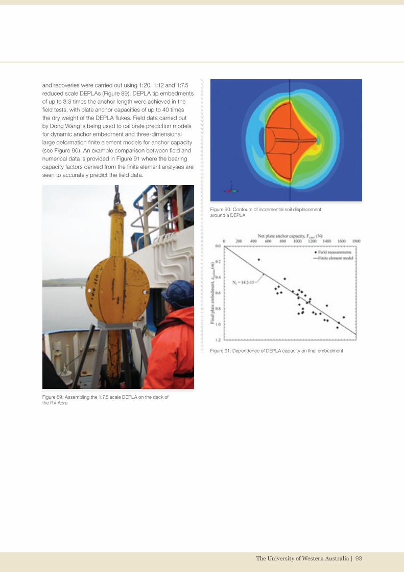
and recoveries were carried out using 1:20, 1:12 and 1:7.5 reduced scale DEPLAs (Figure 89). DEPLA tip embedments of up to 3.3 times the anchor length were achieved in the field tests, with plate anchor capacities of up to 40 times the dry weight of the DEPLA flukes. Field data carried out by Dong Wang is being used to calibrate prediction models for dynamic anchor embedment and three-dimensional large deformation finite element models for anchor capacity (see Figure 90). An example comparison between field and numerical data is provided in Figure 91 where the bearing capacity factors derived from the finite element analyses are seen to accurately predict the field data.
Figure 91: Dependence of DEPLA capacity on final embedment
Figure 89: Assembling the 1:7.5 scale DEPLA on the deck of the RV Aora
Figure 90: Contours of incremental soil displacement around a DEPLA
The University of Western Australia | 93

Behaviour of plate anchor in sandMuch work has been conducted in recent years on the capacity and keying behaviour of plate anchors in clay. However, there have been very few corresponding studies in sand, as clay is the dominant soil type in the deep water environment in which plate anchors are currently used. In the future, the installation of floating wave energy converters and wind turbines in water depths typically less than 100 m may redirect some attention towards the behaviour of plate anchors in sand.
Conleth O’Loughlin has been looking into this problem using centrifuge modelling (see a typical load displacement curve in Figure 92) coupled with image analysis using GeoPIV. Strip anchors with varying padeye eccentricity ratios were vertically embedded in dense silica sand and then loaded vertically.
The most striking observation from the tests was the failure mechanism transition during keying, from a deep localised rotational mechanism to a shallow block mechanism extending to the soil surface (Figure 93). This transition coincided with the peak resistance of the plate and typically occurred when the plate was 60 to 65° to the vertical.
The uplift resistance of the plate as it becomes horizontal is in good agreement with a limit equilibrium solution proposed by Dave White in 2008 that neglects the normality condition and assumes a failure mechanism broadly similar to the eventual failure mechanism of the plate after keying (Figure 94).
Figure 94: Comparison of back figured Nγ from the centrifuge tests with other experimental data and theoretical solutions
Figure 92: Load-displacement response for a padeye eccentricity equal to the plate height, showing plate rotation at various stages during keying
Figure 93: Instantaneous velocity field: (a) at 71% of the peak load (point C), and (b) at the peak load (point D); note axes are in pixels
(a)
(b)
94 | cofs.uwa.edu.au

Physical and numerical modelling of installation and pull-out of dynamically penetrating anchors in clay and siltShazzad Hossain, Christophe Gaudin and Mark Randolph continue to investigate deep water anchoring, notably dynamically penetrating anchors (DPAs). Shazzad has carried out a series of centrifuge model tests at 200 g undertaken to provide insight into the behaviour of DPAs during dynamic installation and monotonic pull-out in normally consolidated clay and calcareous silt. The tests were carried out varying drop height and terminal velocity. The pull-out angle at the mudline was also varied to encompass various mooring systems. Shazzad was awarded a UWA ECM Research Development Grant ($20,000 for 2012~13) for physical and numerical modelling of DPAs. Shazzad and Conleth O’Loughlin are about to carry out a series of centrifuge tests.
Youngho Kim, Shazzad Hossain and Dong Wang are developing numerical models simulating anchor dynamic installation, reconsolidation or set-up and monotonic pull-out. The installation portion isessentially completed, accounting for the combined effects of high rate dependency and gradual softening. The 3D large deformation FE (LDFE) analyses were carried out using the Coupled Eulerian-Lagrangian (CEL) approach in the commercial FE package ABAQUS/Explicit. A parametric study was undertaken, exploring a range of anchor geometry in terms of diameter, tip angle and number and length of fins, impact velocity and soil strength. For dynamic installation, two interesting aspects of the soil flow mechanisms were identified: (i) downward soil movement, concentrating around the advancing anchor, being reduced gradually with reducing penetration velocity and more rapidly with increasing number of fins and anchor projected area, and (ii) mobilisation of end bearing mechanism at the base of the anchor as well as fins, with the latter reduced significantly for shorter fins. The distortion of the soil layers by the advancing anchor is shown in Figure 95, plotting strength contours for the soil after a penetration to the final embedment depth. Interestingly, different amounts of soft soil are trapped beneath and around anchors with and without fins. Softer material is trapped beneath both the anchor tip as well as fins base, resulting in different embedment depths.
Figure 95: Effect of fins on strength contours during dynamic anchor installation
The University of Western Australia | 95

Uplift capacity of helical-shaped anchorHelical anchors are widely used as foundations for transmission towers and pipelines resisting uplift loadings. Helical anchors include a number of helical-shaped circular plates welded to a central steel shaft used to transmit torque during installation and to transfer axial loads to the helical plates. The uplift capacity of helical anchors in clays was investigated in centrifuge by Dong Wang and Christophe Gaudin in 2010, collaborated with Richard Merifield at Newcastle University. In 2012, this study was expanded to finite element studies (Figure 96). A simple method was finally presented to predict the uplift capacities with different combinations of number of plates, plate diameter and spacing, embedment depth and soil strength linearly increased with depth.
(see Figure 97) prior to undertaking a detailed parametric study, exploring the relevant range of non-dimensional parameters, such as stiffened caisson geometry, roughness and soil strength.
Two interesting features of soil flow were identified including soil backflow into the cavities between the embedded stiffeners and soil heaving inside the caisson, as illustrated in Figure 97 and Figure 98. Stiffeners normalised spacing and width were shown to have significant influence on soil heaving and amount of backfilling into a cavity, while caisson diameter to skirt thickness ratio and soil normalised strength and its non-homogeneity on the depths of backflow. Soil flow mechanisms were revealed and simple expressions were proposed for estimating true caisson penetration resistance in non-homogeneous clays.
Figure 96: Soil flow mechanisms varied with plate spacing
Installation of suction caissons with stiffeners Significant differences between predicted and measured resistances were identified for suction caissons with stiffeners based on the field tests results and existing prediction models. These differences are believed to be due to uncertainty in regards to the mobilised soil flow mechanisms during installation of stiffened caisson. Mi Zhou, Shazzad Hossain, Yuxia Hu and Barry Lehane are undertaking an extensive investigation on stiffened caisson penetration in non-homogeneous clays through centrifuge model tests and large deformation FE (LDFE) analyses. The key aim is to identify the soil flow mechanisms around and between lateral ring stiffeners. In centrifuge tests, stiffened plates were penetrated against a window, allowing the soil flow to be captured by a camera and subsequently quantified by particle image velocimetry (PIV) analyses. The LDFE results were validated against centrifuge test data
Figure 98: Mechanism of soil backflow into cavity and soil heaving inside caisson (LDFE, kD/sum = 2.83, sum/γ′D = 0.22)
Figure 97: Mechanism of soil backflow into cavity between embedded stiffeners (model test and LDFE, su = 10 + 0.6z kPa)
96 | cofs.uwa.edu.au

Shallow foundations and pipelinesUplift capacity of skirted foundationsXiaojun Li is continuing his PhD study on the pore pressure generation mechanism in clay and the uplift behaviour of offshore foundations. A series of centrifuge tests have been carried out to investigate the uplift resistance of skirted foundations under increasing displacement rates in lightly over-consolidated kaolin clay. Typically circular and square shaped models have been fabricated to make comparisons between the two (Figure 99). Uplift load, displacements and pore pressures at the foundation invert were monitored during testing. Results provided insights into the development of suction at the foundation invert and its contribution to the uplift resistance of foundations and their associated failure mechanisms in soil. Backbone curves for both the circular and square footings were established, enabling predictions of the level of suction generation and uplift resistance of foundations under drained, partially drained and undrained conditions in soil (Figure 100). Meanwhile, an analytical model combining suction generation caused by uplift, suction dissipation as a function of the uplift rate and breakaway as a function of the boundary conditions is being developed to predict suction generation and uplift resistance for a wide range of geotechnical structures.
Mitigation of the gapping effect on uplift capacity of skirt foundationsDivya Mana, Susan Gourvenec and Mark Randolph continued their investigations on the uplift capacity of skirted foundations through centrifuge modelling. From the centrifuge tests, it was observed that reverse end bearing resistance is mobilised by skirted foundations with even very shallow skirt embedment depth to diameter ratios (up to 0.1), provided the skirt compartment is sealed and there is no gap between the skirt wall and surrounding soil. The presence of a gap leads to sudden loss of suction beneath the top plate and immediate loss of reverse end bearing resistance under short-term uplift loading. Under long-term sustained loading the rate of displacement was doubled and the threshold foundation displacement before loss of suction was halved due to the presence of a gap. In order to mitigate adverse effects of gapping on the uplift capacity, a novel technique has been developed. Centrifuge model tests on skirted foundations equipped with a flexible mat around the periphery of the foundations called a “gap arrestor” (Figure 101) gave promising results by considerably improving both the short- and long-term uplift capacity in the presence of a gap.
Figure 100: Backbone curve for uplift resistance
Figure 99: Reduced scale models used in test
0.1 1 10 100 1000 100000
2
4
6
8
10
12
Nor
mal
ised
upl
ift re
sist
ance
, qm/q
f
Normalised veloctiy, V
Circular Square
Figure 101: Side elevation of the skirted foundation model with d/D = 0.1 (a) without gap arrestor and (b) with gap arrestor
The University of Western Australia | 97

Optimisation of subsea mudmats under 6 degree-of-freedom loading Xiaowei Feng, Susan Gourvenec and Mark Randolph continued investigations into the 6 degree-of-freedom loading capacity of subsea mudmat foundations (Figure 102). The study considers rectangular mudmats with a length to breadth aspect ratio of 2 and embedment ratios from 0 (surface foundation) to 0.2. Undrained soil conditions are assumed, considering various normally consolidated linearly increasing shear strength profiles and strength profiles with a surface crust. The results are interpreted through the failure envelope method, encapsulated in a design methodology and presented in a spread-sheet based design tool.
A strategy for improving subsea mudmat capacity through provision of corner pin-piles has been investigated through finite element analysis by Xiaowei Feng, Toru Watanabe, Susan Gourvenec and Mark Randolph. The research has shown that lateral and moment capacity of the mudmat can be considerably enhanced by the piles and by the pile/mat interaction (Figure 103).
Hybrid foundation systemThe final year of the Linkage project between Okky Purwana from Keppel Offshore & Marine Technology Centre in Singapore and Christophe Gaudin, Britta Bienen and Mark Cassidy saw developments on multiple fronts. Previous findings from numerical studies of the undrained capacity under combined VHM loading of a simplified hybrid footing consisting of a circular skirted mat with one central caisson compartment for self-installation were published in two journal papers. With the help of Dengfeng Fu, a visitor enrolling as a PhD student in 2013, the undrained capacity of a more complex hybrid footing geometry, featuring a rectangular skirted mat with two caisson units (Figure 104), was investigated numerically. Figure 105 presents some of the results highlighting the failure envelope in the My – Hx loading planes for the hybrid foundation compared with that of a skirted rectangular foundation, and the failure mechanism for both foundations along key points of the failure envelope. Results demonstrated significant increases in horizontal and torsional capacity often required in subsea installations compared to a conventional skirted mat. This is associated with new failure mechanism for the hybrid foundation that differs both in size and shape compared to conventional skirted foundations, due to the presence of the caissons.
Figure 103: Deformation of mudmat with corner pin-piles subjected to 6 degree-of-freedom loading
Figure 102: 6 degree-of-freedom loading of subsea mudmat
Figure 105: Comparison of failure envelopes for My – HX loading between the hybrid foundation and skirted rectangular foundation (V = 0)
Figure 104: Hybrid foundation geometry with two suction caissons
In parallel, Steven Cheng, assisted by Youhu Zhang, performed additional centrifuge tests on a circular mat with central suction caisson to establish VHM yield envelopes, and evaluate the influence of the caisson. The tests used
98 | cofs.uwa.edu.au

Lateral break-out resistance of pipelinesSusan Gourvenec and David White used centrifuge modelling to quantify increased lateral break-out resistance of partially embedded pipelines in soft soil due to installation effects. Monotonic vertical installation, or ‘zig-zag’ cyclic installation (to mimic disturbance during pipe lay,) followed by immediate break-out or a period of consolidation prior to break-out was modelled to investigate the effects of remoulding and reconsolidation on pipe resistance. Post-installation re-consolidation, particularly following cyclic installation led to a marked increase in lateral break-out resistance compared to unconsolidated break out (Figure 108). The centrifuge results are currently being back analysed by LDFEA.
the new VHM actuator developed by Youhu Zhang, Britta Bienen and Mark Cassidy in the drum centrifuge, to provide a high level of accuracy when performing swipe and probe tests (Figure 106). Results demonstrated that the caisson significantly increased the horizontal capacity, but only marginally increased the vertical and moment capacity if the caisson does not intercept the failure mechanism observed for a circular skirted foundation. This result was also observed during the numerical analysis.
Figure 106: VHM setup of hybrid foundation
Figure 107: PIV analysis of skirted foundations with and without preloading
Figure 108: Lateral break-out response of an embedded pipe in soft soil
Assisted by visitor Minh Tri Duong, Sam Stanier and Christophe Gaudin undertook PIV analysis of skirted foundations with and without preloading. The aim is to correlate the increase in capacity resulting from preloading to both the change in strength occurring during consolidation and the change in failure mechanism resulting from the new strength distribution after preloading. The analysis demonstrated that the preloading and associated soil consolidation results in a post-preloading failure mechanism featuring essentially vertical deformations, such as in a punch through mechanism (Figure 107). Further analysis is currently in progress to establish bearing capacity factors for preloaded foundations.
The University of Western Australia | 99