Embed Size (px)
Citation preview
© 2021 The Author(s). Published by the Royal Society of Chemistry Mater. Adv., 2021, 2, 3031–3041 | 3031
Cite this: Mater. Adv., 2021,
2, 3031
Protective interlayer for trapping polysulfides anda conducting host for sulfur: dual role of candlesoot carbon for the development of highperformance lithium–sulfur batteries†
Vikram K. Bharti, Ananya Gangadharan, S. Krishna Kumar, Anil D. Pathak andChandra S. Sharma *
The commercial realization of next-generation lithium–sulfur (Li–S) batteries is mainly hindered due to
the unwanted lithium polysulfide shuttling and the insulating nature of the sulfur cathode. In the present
work, we aim to overcome these critical challenges by the first-time usage of candle soot carbon as a
conducting host as well as an inbuilt interlayer. The Li–S battery thus fabricated delivers an impressive
capacity of 1182 mA h g�1 with 92% coulombic efficiency at 0.1C. This excellent electrochemical perfor-
mance is further maintained in long cycling even at a higher C-rate (1C) and exhibits a capacity of
667 mA h g�1 after 200 cycles with coulombic efficiency B95% (an extremely slow capacity decay rate
of 0.03% per cycle). Moreover, for a high-sulfur loading (4.5 mg cm�2) electrode the Li–S battery retains
61.3% of the initial capacity after cycling for 150 cycles at 2.0C. Further, to understand the functional
mechanism of the carbon interlayer for anchoring lithium polysulfides, first principles calculations are
performed based on density functional theory. To the best of our knowledge, this is the first such report
on using inexpensive candle soot carbon as a cathode host and as an interlayer that results in outstanding
electrochemical performance.
1. Introduction
Lithium–sulfur (Li–S) batteries have gained a paramount positionin the field of electrochemical energy storage devices in the lastdecade owing to their high theoretical specific energy density(2600 W h kg�1) and specific capacity (1675 mA h g�1).1–3 This isnearly five-fold higher than the commercialized lithium-ion bat-teries based on an intercalation mechanism, due to the redoxkinetics (i.e., two-electron transfer) involved in the electrochemicalreaction of lithium ions with sulfur.4 In addition, the non-toxicityand natural abundance of sulfur offer additional advantages forimmense research on Li–S batteries.5 However, there are still manybarriers to overcome for the fulfilment of commercial Li–S batteries.Firstly, the insulating nature of sulfur (ca. 5 � 10�30 S cm�1) andreaction product Li2S (ca. 10�13 S cm�1) impedes the electronicmobility during the electrochemical reaction, resulting in sluggishreaction kinetics and low utilization of active sulfur. Secondly, thedensity difference between the electrochemical end product Li2S
and sulfur (1.66 and 2.07 g cm�3, respectively) causes volumeexpansion in the electrode, resulting in electrode pulverizationand cathode degradation leading to limited life span of the Li–Sbattery.6,7 Thirdly, the dissolution of intermediate long-chainlithium polysulfides (Li2Sx, 4 r x r 8) in the electrolyte, termedas ‘‘shuttle behavior’’, causes loss of active material (sulfur) anddeposition of short-chain lithium polysulfides (Li2S2/Li2S) on thelithium anode surface resulting in passivation of the anode.6–9
Therefore, for achieving a suitable conducting cathode, the hostmaterial for sulfur plays an important role. Carbon is considered asa potential host for sulfur because of its electrical conductivity andfeasibility to adjust the particle size, pore volume and surface area,which can help in the effective trapping of polysulfides.10 Severalstudies have reported that different carbon structures such ascarbon nanotubes (CNTs), carbon nanofibers (CNFs), carbon nano-sheets and graphene can act as a good host for sulfur.11–14 Besides,different biomass-derived carbons such as carbon derived fromyeast,15 coconut shell,16 cherry pit,17 egg shell,18 silk cocoon,19
luffa sponge,20 banana peel,21 bamboo char22 and rice popcorn23
have also been reported to be efficient hosts from the perspectiveof being cost effective, environmentally friendly and naturallyabundant.
Another important concern for Li–S batteries is the trappingof soluble long-chain lithium polysulfides to retain the battery
Creative & Advanced Research Based on Nanomaterials (CARBON) Laboratory,
Department of Chemical Engineering, Indian Institute of Technology Hyderabad,
Kandi-502285, Telangana, India. E-mail: [email protected]
† Electronic supplementary information (ESI) available. See DOI: 10.1039/d1ma00115a
Received 7th February 2021,Accepted 20th March 2021
DOI: 10.1039/d1ma00115a
rsc.li/materials-advances
MaterialsAdvances
PAPER
Ope
n A
cces
s A
rtic
le. P
ublis
hed
on 2
2 M
arch
202
1. D
ownl
oade
d on
2/7
/202
2 2:
14:3
0 A
M.
Thi
s ar
ticle
is li
cens
ed u
nder
a C
reat
ive
Com
mon
s A
ttrib
utio
n-N
onC
omm
erci
al 3
.0 U
npor
ted
Lic
ence
.
View Article OnlineView Journal | View Issue
3032 | Mater. Adv., 2021, 2, 3031–3041 © 2021 The Author(s). Published by the Royal Society of Chemistry
cycle life without capacity fading. Manthiram et al.24 intro-duced the concept of an interlayer, a physical barricadebetween the cathode and the separator, to inhibit the move-ment of long-chain (higher order) lithium polysulfides from thecathode to the electrolyte. Moreover, the interlayer provides analternative site for the adsorption of long-chain lithium poly-sulfides via physisorption or chemisorption, preventing the lossof active material (sulfur). Therefore, the cell can be operatedfor a long cycle life without capacity loss.20 The pioneering workby X. Gao et al.25–28 shed light on the use of carbon materialswith various strategies for enhancing the electrochemical per-formance. The group has reported the use of a multifunctionalglobular polypyrrole interlayer27 as a polysulfide blockade,which showed impressive electrochemical performance with74% capacity retention on cycling at 0.5C. In the following workby the group,28 they designed a porous hollow carbon aerogelusing CaCO3 as a template and investigated the same as acathode for Li–S batteries. The as prepared cathode exhibitedexcellent cycling with 60.5% capacity retention at 0.1C with asulfur loading of 2.2 mg cm�2. Moreover, the promisingresults reported by several research groups29–31 emphasize thatinterlayer modification of Li–S batteries is a viable and efficientdesign method to block long-chain lithium polysulfideshuttling.
Herein, our approach is to create a conducting host as wellas an inbuilt interlayer (as a polysulfide blockade) from thesame source of carbon for enhanced interfacing between theelectrode and interlayer. For this purpose, we chose an inex-pensive combustion byproduct, candle soot, to play the dualrole of an electrode inbuilt interlayer and a conducting host.The importance of this work lies in the development of aninbuilt candle soot interlayer over a candle soot–sulfur compo-site (SC) which can act as an excellent adhesive interlayer to thecathode and also nullify the polysulfide shuttling to a largeextent. The enhancement of the capacity and cycle life with thecandle soot interlayer is further verified by the electrochemicalperformances using cells with the interlayer (C-SC) and withoutthe interlayer (SC). The candle soot interlayer showed improve-ment in the capacity and cycle life. SC delivered a capacity of874 mA h g�1 at 0.1C which reduced to 193 mA h g�1 at acurrent rate of 6.0C, whereas C-SC exhibited an impressivereversible capacity of 1182 and 486 mA h g�1 at current rates of0.1 and 6.0C, respectively. Moreover, C-SC retained a capacityof 710 mA h g�1 at 1.0C with 94% capacity retention over200 cycles due to the inbuilt interlayer over the electrode, whichprovides alternative sites for the adsorption of long-chainlithium polysulfides. Later, the electrochemical performancewas studied with SC and C-SC high-sulfur loading (4.5 mg cm�2)electrodes. During long-term cyclic stability testing, C-SC wasable to retain 61.3% of the initial capacity after 150 cycles at2.0C, while SC was able to retain only 16.9% of the initialcapacity, reflecting the potential of the inbuilt interlayer.Furthermore, the experimental results were supported with firstprinciples simulation studies, allowing in-depth understandingof the adsorption of higher order polysulfides over the carbon-based candle soot material.
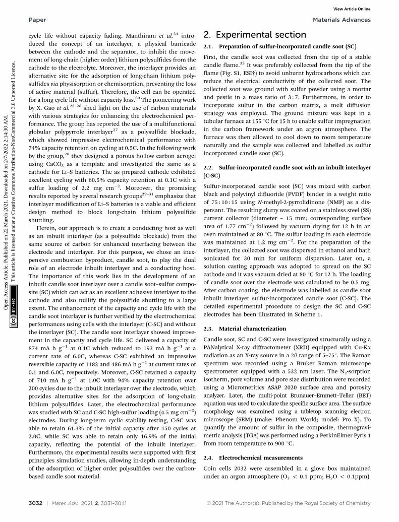
2. Experimental section2.1. Preparation of sulfur-incorporated candle soot (SC)
First, the candle soot was collected from the tip of a stablecandle flame.32 It was preferably collected from the tip of theflame (Fig. S1, ESI†) to avoid unburnt hydrocarbons which canreduce the electrical conductivity of the collected soot. Thecollected soot was ground with sulfur powder using a mortarand pestle in a mass ratio of 3 : 7. Furthermore, in order toincorporate sulfur in the carbon matrix, a melt diffusionstrategy was employed. The ground mixture was kept in atubular furnace at 155 1C for 15 h to enable sulfur impregnationin the carbon framework under an argon atmosphere. Thefurnace was then allowed to cool down to room temperaturenaturally and the sample was collected and labelled as sulfurincorporated candle soot (SC).
2.2. Sulfur-incorporated candle soot with an inbuilt interlayer(C-SC)
Sulfur-incorporated candle soot (SC) was mixed with carbonblack and polyvinyl difluoride (PVDF) binder in a weight ratioof 75 : 10 : 15 using N-methyl-2-pyrrolidinone (NMP) as a dis-persant. The resulting slurry was coated on a stainless steel (SS)current collector (diameter – 15 mm; corresponding surfacearea of 1.77 cm�2) followed by vacuum drying for 12 h in anoven maintained at 80 1C. The sulfur loading in each electrodewas maintained at 1.2 mg cm�2. For the preparation of theinterlayer, the collected soot was dispersed in ethanol and bathsonicated for 30 min for uniform dispersion. Later on, asolution casting approach was adopted to spread on the SCcathode and it was vacuum dried at 80 1C for 12 h. The loadingof candle soot over the electrode was calculated to be 0.5 mg.After carbon coating, the electrode was labelled as candle sootinbuilt interlayer sulfur-incorporated candle soot (C-SC). Thedetailed experimental procedure to design the SC and C-SCelectrodes has been illustrated in Scheme 1.
2.3. Material characterization
Candle soot, SC and C-SC were investigated structurally using aPANalytical X-ray diffractometer (XRD) equipped with Cu-Karadiation as an X-ray source in a 2y range of 5–751. The Ramanspectrum was recorded using a Bruker Raman microscopespectrometer equipped with a 532 nm laser. The N2-sorptionisotherm, pore volume and pore size distribution were recordedusing a Micromeritics ASAP 2020 surface area and porosityanalyzer. Later, the multi-point Brunauer–Emmett–Teller (BET)equation was used to calculate the specific surface area. The surfacemorphology was examined using a tabletop scanning electronmicroscope (SEM) (make: Phenom World; model: Pro X). Toquantify the amount of sulfur in the composite, thermogravi-metric analysis (TGA) was performed using a PerkinElmer Pyris 1from room temperature to 900 1C.
2.4. Electrochemical measurements
Coin cells 2032 were assembled in a glove box maintainedunder an argon atmosphere (O2 o 0.1 ppm; H2O o 0.1ppm).
Paper Materials Advances
Ope
n A
cces
s A
rtic
le. P
ublis
hed
on 2
2 M
arch
202
1. D
ownl
oade
d on
2/7
/202
2 2:
14:3
0 A
M.
Thi
s ar
ticle
is li
cens
ed u
nder
a C
reat
ive
Com
mon
s A
ttrib
utio
n-N
onC
omm
erci
al 3
.0 U
npor
ted
Lic
ence
.View Article Online
© 2021 The Author(s). Published by the Royal Society of Chemistry Mater. Adv., 2021, 2, 3031–3041 | 3033
In the assembly, the SC and C-SC electrodes were used as thecathode, lithium foil (diameter – 15 mm) as the counter/reference electrode, and glass microfiber (diameter – 19 mm)as a separator. 1.0 M lithium bis-(trifluoromethanesulfonyl)imide (LiTFSI) salt dissolved in a solvent mixture of dimethoxy-ethane (DME) and 1,3-dioxolane (DOL) (1 : 1 v/v) containing0.1 M LiNO3 as an additive was prepared and used as anelectrolyte. The electrolyte volume between the different cath-odes and the lithium anode was controlled to about 60 mL.Galvanostatic charge–discharge measurements were performedusing a Biologic VSP 300 in the potential range of 1.7–3.0 V(vs. Li/Li+). The cyclic voltammogram (CV) measurement wascarried out in a potential window of 1.7–3.0 V (vs. Li/Li+) at ascan rate of 0.1 mV s�1. Electrochemical impedance spectro-scopy (EIS) was conducted using a Biologic VSP 300 electro-chemical workstation in the frequency range of 0.01 Hz to1 MHz at room temperature.
2.5. Computational method
The optimization of all the structures was carried out with thebasis set of STO-3G and the B3LYP level of theory, as reportedin previous work,33–38 using the Gaussian 09 software package.The total binding energy of the systems was calculated usingthe following equation: EBE = EC–Li2Sx
� (EC + ELi2Sx), where EBE
represents the total binding energy between carbon and poly-sulfide species Li2Sx (x = 4, 6, 8). EC–Li2Sx
, ELi2Sxand EC are the
energies of polysulfides with carbon (C–Li2Sn), long-chainlithium polysulfides (Li2Sx) and carbon (C), respectively.
3. Results and discussion
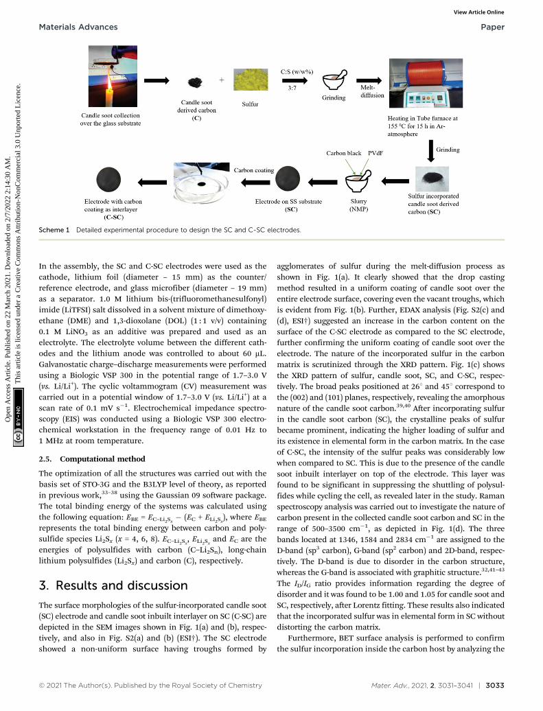
The surface morphologies of the sulfur-incorporated candle soot(SC) electrode and candle soot inbuilt interlayer on SC (C-SC) aredepicted in the SEM images shown in Fig. 1(a) and (b), respec-tively, and also in Fig. S2(a) and (b) (ESI†). The SC electrodeshowed a non-uniform surface having troughs formed by
agglomerates of sulfur during the melt-diffusion process asshown in Fig. 1(a). It clearly showed that the drop castingmethod resulted in a uniform coating of candle soot over theentire electrode surface, covering even the vacant troughs, whichis evident from Fig. 1(b). Further, EDAX analysis (Fig. S2(c) and(d), ESI†) suggested an increase in the carbon content on thesurface of the C-SC electrode as compared to the SC electrode,further confirming the uniform coating of candle soot over theelectrode. The nature of the incorporated sulfur in the carbonmatrix is scrutinized through the XRD pattern. Fig. 1(c) showsthe XRD pattern of sulfur, candle soot, SC, and C-SC, respec-tively. The broad peaks positioned at 261 and 451 correspond tothe (002) and (101) planes, respectively, revealing the amorphousnature of the candle soot carbon.39,40 After incorporating sulfurin the candle soot carbon (SC), the crystalline peaks of sulfurbecame prominent, indicating the higher loading of sulfur andits existence in elemental form in the carbon matrix. In the caseof C-SC, the intensity of the sulfur peaks was considerably lowwhen compared to SC. This is due to the presence of the candlesoot inbuilt interlayer on top of the electrode. This layer wasfound to be significant in suppressing the shuttling of polysul-fides while cycling the cell, as revealed later in the study. Ramanspectroscopy analysis was carried out to investigate the nature ofcarbon present in the collected candle soot carbon and SC in therange of 500–3500 cm�1, as depicted in Fig. 1(d). The threebands located at 1346, 1584 and 2834 cm�1 are assigned to theD-band (sp3 carbon), G-band (sp2 carbon) and 2D-band, respec-tively. The D-band is due to disorder in the carbon structure,whereas the G-band is associated with graphitic structure.32,41–43
The ID/IG ratio provides information regarding the degree ofdisorder and it was found to be 1.00 and 1.05 for candle soot andSC, respectively, after Lorentz fitting. These results also indicatedthat the incorporated sulfur was in elemental form in SC withoutdistorting the carbon matrix.
Furthermore, BET surface analysis is performed to confirmthe sulfur incorporation inside the carbon host by analyzing the
Scheme 1 Detailed experimental procedure to design the SC and C-SC electrodes.
Materials Advances Paper
Ope
n A
cces
s A
rtic
le. P
ublis
hed
on 2
2 M
arch
202
1. D
ownl
oade
d on
2/7
/202
2 2:
14:3
0 A
M.
Thi
s ar
ticle
is li
cens
ed u
nder
a C
reat
ive
Com
mon
s A
ttrib
utio
n-N
onC
omm
erci
al 3
.0 U
npor
ted
Lic
ence
.View Article Online
3034 | Mater. Adv., 2021, 2, 3031–3041 © 2021 The Author(s). Published by the Royal Society of Chemistry
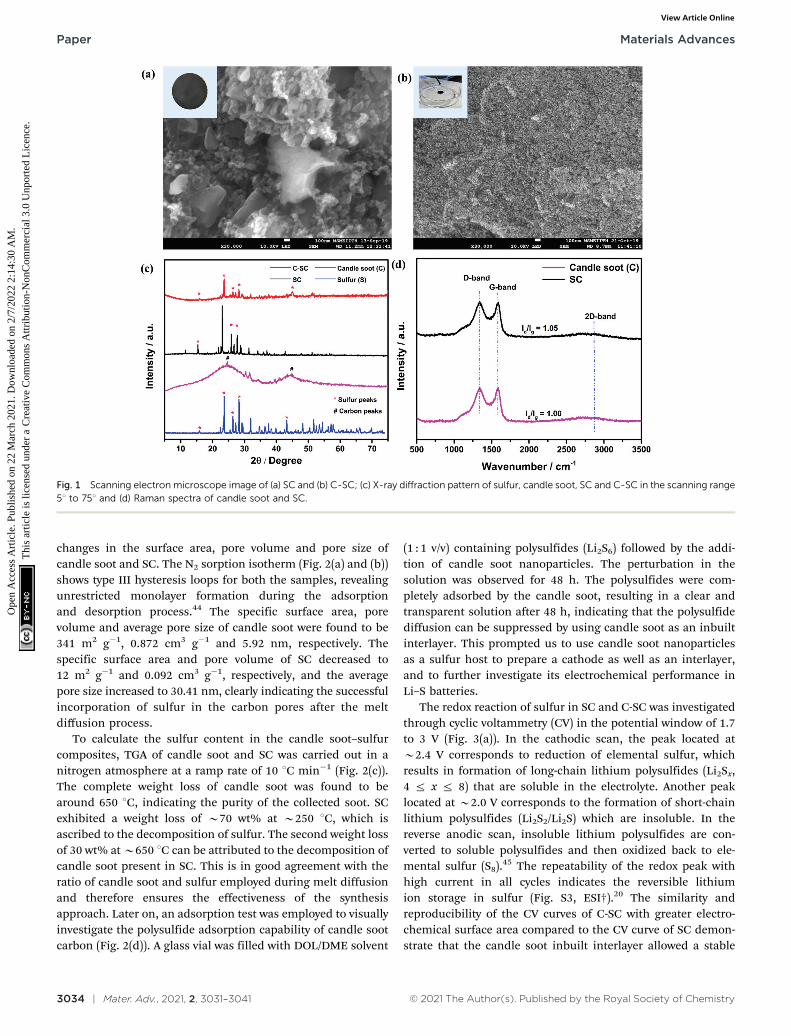
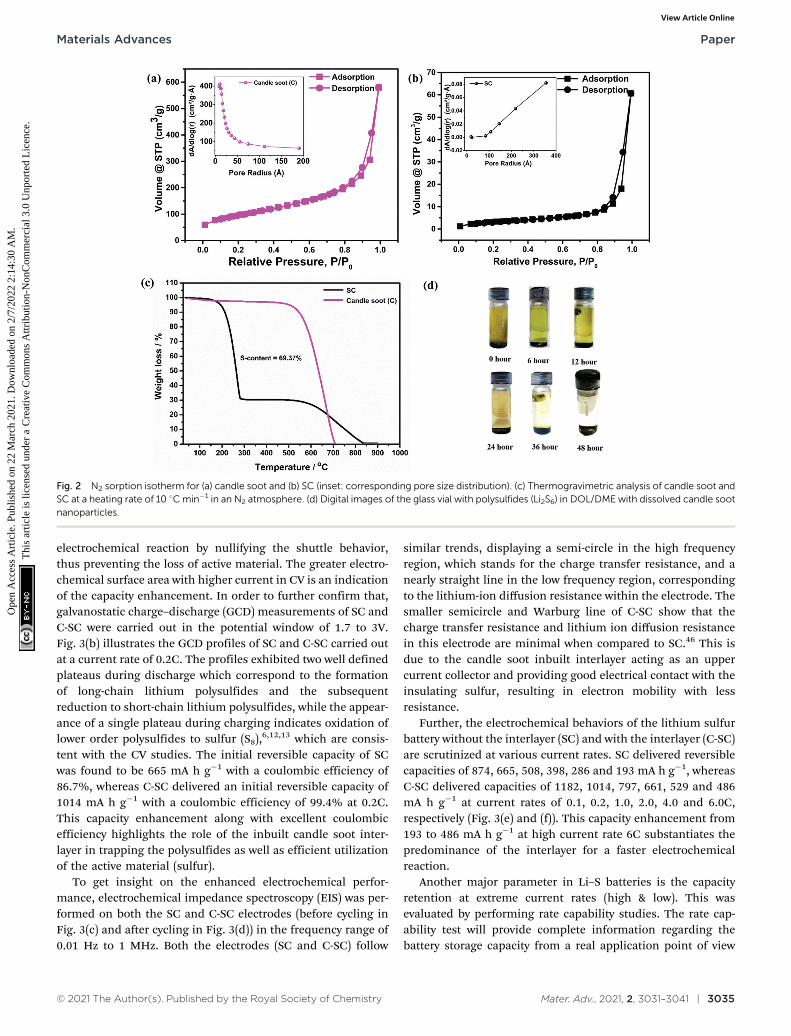
changes in the surface area, pore volume and pore size ofcandle soot and SC. The N2 sorption isotherm (Fig. 2(a) and (b))shows type III hysteresis loops for both the samples, revealingunrestricted monolayer formation during the adsorptionand desorption process.44 The specific surface area, porevolume and average pore size of candle soot were found to be341 m2 g�1, 0.872 cm3 g�1 and 5.92 nm, respectively. Thespecific surface area and pore volume of SC decreased to12 m2 g�1 and 0.092 cm3 g�1, respectively, and the averagepore size increased to 30.41 nm, clearly indicating the successfulincorporation of sulfur in the carbon pores after the meltdiffusion process.
To calculate the sulfur content in the candle soot–sulfurcomposites, TGA of candle soot and SC was carried out in anitrogen atmosphere at a ramp rate of 10 1C min�1 (Fig. 2(c)).The complete weight loss of candle soot was found to bearound 650 1C, indicating the purity of the collected soot. SCexhibited a weight loss of B70 wt% at B250 1C, which isascribed to the decomposition of sulfur. The second weight lossof 30 wt% at B650 1C can be attributed to the decomposition ofcandle soot present in SC. This is in good agreement with theratio of candle soot and sulfur employed during melt diffusionand therefore ensures the effectiveness of the synthesisapproach. Later on, an adsorption test was employed to visuallyinvestigate the polysulfide adsorption capability of candle sootcarbon (Fig. 2(d)). A glass vial was filled with DOL/DME solvent
(1 : 1 v/v) containing polysulfides (Li2S6) followed by the addi-tion of candle soot nanoparticles. The perturbation in thesolution was observed for 48 h. The polysulfides were com-pletely adsorbed by the candle soot, resulting in a clear andtransparent solution after 48 h, indicating that the polysulfidediffusion can be suppressed by using candle soot as an inbuiltinterlayer. This prompted us to use candle soot nanoparticlesas a sulfur host to prepare a cathode as well as an interlayer,and to further investigate its electrochemical performance inLi–S batteries.
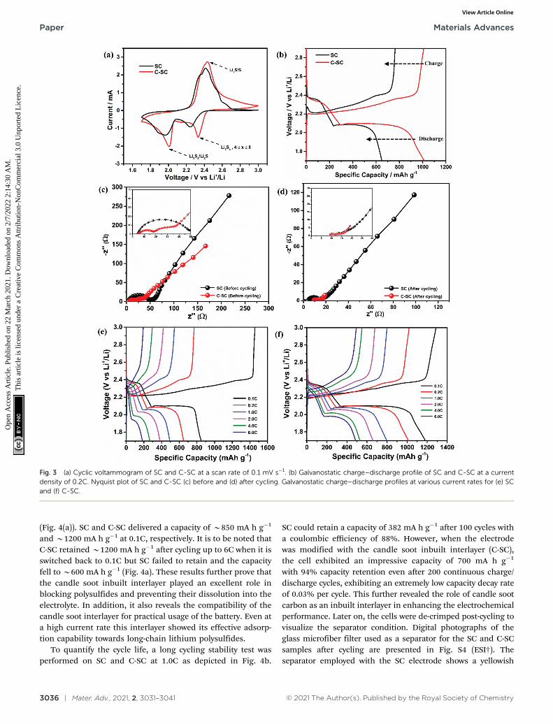
The redox reaction of sulfur in SC and C-SC was investigatedthrough cyclic voltammetry (CV) in the potential window of 1.7to 3 V (Fig. 3(a)). In the cathodic scan, the peak located atB2.4 V corresponds to reduction of elemental sulfur, whichresults in formation of long-chain lithium polysulfides (Li2Sx,4 r x r 8) that are soluble in the electrolyte. Another peaklocated at B2.0 V corresponds to the formation of short-chainlithium polysulfides (Li2S2/Li2S) which are insoluble. In thereverse anodic scan, insoluble lithium polysulfides are con-verted to soluble polysulfides and then oxidized back to ele-mental sulfur (S8).45 The repeatability of the redox peak withhigh current in all cycles indicates the reversible lithiumion storage in sulfur (Fig. S3, ESI†).20 The similarity andreproducibility of the CV curves of C-SC with greater electro-chemical surface area compared to the CV curve of SC demon-strate that the candle soot inbuilt interlayer allowed a stable
Fig. 1 Scanning electron microscope image of (a) SC and (b) C-SC; (c) X-ray diffraction pattern of sulfur, candle soot, SC and C-SC in the scanning range51 to 751 and (d) Raman spectra of candle soot and SC.
Paper Materials Advances
Ope
n A
cces
s A
rtic
le. P
ublis
hed
on 2
2 M
arch
202
1. D
ownl
oade
d on
2/7
/202
2 2:
14:3
0 A
M.
Thi
s ar
ticle
is li
cens
ed u
nder
a C
reat
ive
Com
mon
s A
ttrib
utio
n-N
onC
omm
erci
al 3
.0 U
npor
ted
Lic
ence
.View Article Online
© 2021 The Author(s). Published by the Royal Society of Chemistry Mater. Adv., 2021, 2, 3031–3041 | 3035
electrochemical reaction by nullifying the shuttle behavior,thus preventing the loss of active material. The greater electro-chemical surface area with higher current in CV is an indicationof the capacity enhancement. In order to further confirm that,galvanostatic charge–discharge (GCD) measurements of SC andC-SC were carried out in the potential window of 1.7 to 3V.Fig. 3(b) illustrates the GCD profiles of SC and C-SC carried outat a current rate of 0.2C. The profiles exhibited two well definedplateaus during discharge which correspond to the formationof long-chain lithium polysulfides and the subsequentreduction to short-chain lithium polysulfides, while the appear-ance of a single plateau during charging indicates oxidation oflower order polysulfides to sulfur (S8),6,12,13 which are consis-tent with the CV studies. The initial reversible capacity of SCwas found to be 665 mA h g�1 with a coulombic efficiency of86.7%, whereas C-SC delivered an initial reversible capacity of1014 mA h g�1 with a coulombic efficiency of 99.4% at 0.2C.This capacity enhancement along with excellent coulombicefficiency highlights the role of the inbuilt candle soot inter-layer in trapping the polysulfides as well as efficient utilizationof the active material (sulfur).
To get insight on the enhanced electrochemical perfor-mance, electrochemical impedance spectroscopy (EIS) was per-formed on both the SC and C-SC electrodes (before cycling inFig. 3(c) and after cycling in Fig. 3(d)) in the frequency range of0.01 Hz to 1 MHz. Both the electrodes (SC and C-SC) follow
similar trends, displaying a semi-circle in the high frequencyregion, which stands for the charge transfer resistance, and anearly straight line in the low frequency region, correspondingto the lithium-ion diffusion resistance within the electrode. Thesmaller semicircle and Warburg line of C-SC show that thecharge transfer resistance and lithium ion diffusion resistancein this electrode are minimal when compared to SC.46 This isdue to the candle soot inbuilt interlayer acting as an uppercurrent collector and providing good electrical contact with theinsulating sulfur, resulting in electron mobility with lessresistance.
Further, the electrochemical behaviors of the lithium sulfurbattery without the interlayer (SC) and with the interlayer (C-SC)are scrutinized at various current rates. SC delivered reversiblecapacities of 874, 665, 508, 398, 286 and 193 mA h g�1, whereasC-SC delivered capacities of 1182, 1014, 797, 661, 529 and 486mA h g�1 at current rates of 0.1, 0.2, 1.0, 2.0, 4.0 and 6.0C,respectively (Fig. 3(e) and (f)). This capacity enhancement from193 to 486 mA h g�1 at high current rate 6C substantiates thepredominance of the interlayer for a faster electrochemicalreaction.
Another major parameter in Li–S batteries is the capacityretention at extreme current rates (high & low). This wasevaluated by performing rate capability studies. The rate cap-ability test will provide complete information regarding thebattery storage capacity from a real application point of view
Fig. 2 N2 sorption isotherm for (a) candle soot and (b) SC (inset: corresponding pore size distribution). (c) Thermogravimetric analysis of candle soot andSC at a heating rate of 10 1C min�1 in an N2 atmosphere. (d) Digital images of the glass vial with polysulfides (Li2S6) in DOL/DME with dissolved candle sootnanoparticles.
Materials Advances Paper
Ope
n A
cces
s A
rtic
le. P
ublis
hed
on 2
2 M
arch
202
1. D
ownl
oade
d on
2/7
/202
2 2:
14:3
0 A
M.
Thi
s ar
ticle
is li
cens
ed u
nder
a C
reat
ive
Com
mon
s A
ttrib
utio
n-N
onC
omm
erci
al 3
.0 U
npor
ted
Lic
ence
.View Article Online
3036 | Mater. Adv., 2021, 2, 3031–3041 © 2021 The Author(s). Published by the Royal Society of Chemistry
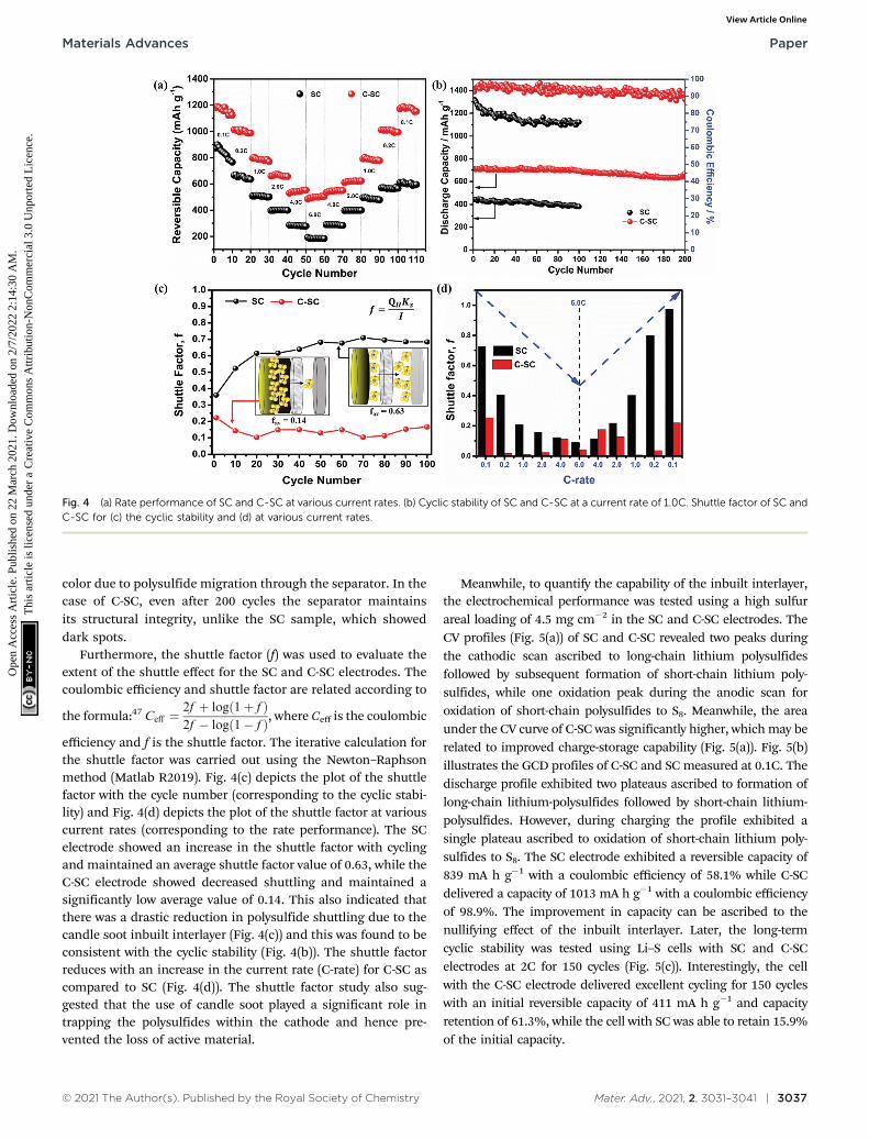
(Fig. 4(a)). SC and C-SC delivered a capacity of B850 mA h g�1
and B1200 mA h g�1 at 0.1C, respectively. It is to be noted thatC-SC retained B1200 mA h g�1 after cycling up to 6C when it isswitched back to 0.1C but SC failed to retain and the capacityfell to B600 mA h g�1 (Fig. 4a). These results further prove thatthe candle soot inbuilt interlayer played an excellent role inblocking polysulfides and preventing their dissolution into theelectrolyte. In addition, it also reveals the compatibility of thecandle soot interlayer for practical usage of the battery. Even ata high current rate this interlayer showed its effective adsorp-tion capability towards long-chain lithium polysulfides.
To quantify the cycle life, a long cycling stability test wasperformed on SC and C-SC at 1.0C as depicted in Fig. 4b.
SC could retain a capacity of 382 mA h g�1 after 100 cycles witha coulombic efficiency of 88%. However, when the electrodewas modified with the candle soot inbuilt interlayer (C-SC),the cell exhibited an impressive capacity of 700 mA h g�1
with 94% capacity retention even after 200 continuous charge/discharge cycles, exhibiting an extremely low capacity decay rateof 0.03% per cycle. This further revealed the role of candle sootcarbon as an inbuilt interlayer in enhancing the electrochemicalperformance. Later on, the cells were de-crimped post-cycling tovisualize the separator condition. Digital photographs of theglass microfiber filter used as a separator for the SC and C-SCsamples after cycling are presented in Fig. S4 (ESI†). Theseparator employed with the SC electrode shows a yellowish
Fig. 3 (a) Cyclic voltammogram of SC and C-SC at a scan rate of 0.1 mV s�1. (b) Galvanostatic charge–discharge profile of SC and C-SC at a currentdensity of 0.2C. Nyquist plot of SC and C-SC (c) before and (d) after cycling. Galvanostatic charge–discharge profiles at various current rates for (e) SCand (f) C-SC.
Paper Materials Advances
Ope
n A
cces
s A
rtic
le. P
ublis
hed
on 2
2 M
arch
202
1. D
ownl
oade
d on
2/7
/202
2 2:
14:3
0 A
M.
Thi
s ar
ticle
is li
cens
ed u
nder
a C
reat
ive
Com
mon
s A
ttrib
utio
n-N
onC
omm
erci
al 3
.0 U
npor
ted
Lic
ence
.View Article Online
© 2021 The Author(s). Published by the Royal Society of Chemistry Mater. Adv., 2021, 2, 3031–3041 | 3037
color due to polysulfide migration through the separator. In thecase of C-SC, even after 200 cycles the separator maintainsits structural integrity, unlike the SC sample, which showeddark spots.
Furthermore, the shuttle factor (f) was used to evaluate theextent of the shuttle effect for the SC and C-SC electrodes. Thecoulombic efficiency and shuttle factor are related according to
the formula:47 Ceff ¼2f þ log 1þ fð Þ2f � log 1� fð Þ, where Ceff is the coulombic
efficiency and f is the shuttle factor. The iterative calculation forthe shuttle factor was carried out using the Newton–Raphsonmethod (Matlab R2019). Fig. 4(c) depicts the plot of the shuttlefactor with the cycle number (corresponding to the cyclic stabi-lity) and Fig. 4(d) depicts the plot of the shuttle factor at variouscurrent rates (corresponding to the rate performance). The SCelectrode showed an increase in the shuttle factor with cyclingand maintained an average shuttle factor value of 0.63, while theC-SC electrode showed decreased shuttling and maintained asignificantly low average value of 0.14. This also indicated thatthere was a drastic reduction in polysulfide shuttling due to thecandle soot inbuilt interlayer (Fig. 4(c)) and this was found to beconsistent with the cyclic stability (Fig. 4(b)). The shuttle factorreduces with an increase in the current rate (C-rate) for C-SC ascompared to SC (Fig. 4(d)). The shuttle factor study also sug-gested that the use of candle soot played a significant role intrapping the polysulfides within the cathode and hence pre-vented the loss of active material.
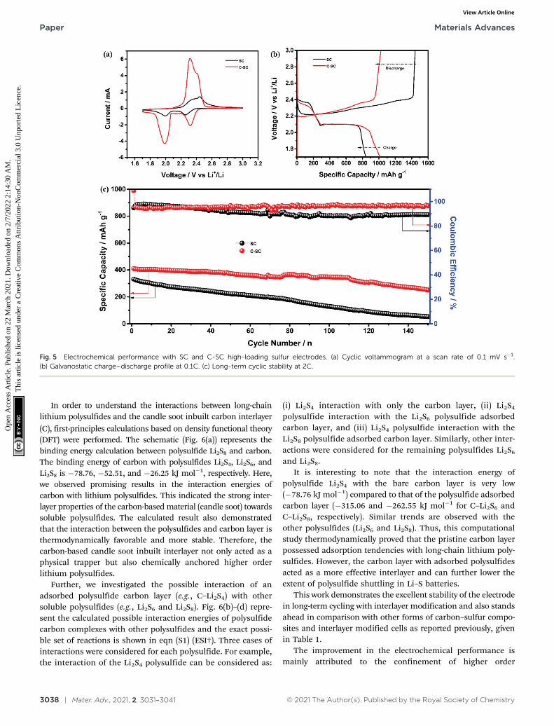
Meanwhile, to quantify the capability of the inbuilt interlayer,the electrochemical performance was tested using a high sulfurareal loading of 4.5 mg cm�2 in the SC and C-SC electrodes. TheCV profiles (Fig. 5(a)) of SC and C-SC revealed two peaks duringthe cathodic scan ascribed to long-chain lithium polysulfidesfollowed by subsequent formation of short-chain lithium poly-sulfides, while one oxidation peak during the anodic scan foroxidation of short-chain polysulfides to S8. Meanwhile, the areaunder the CV curve of C-SC was significantly higher, which may berelated to improved charge-storage capability (Fig. 5(a)). Fig. 5(b)illustrates the GCD profiles of C-SC and SC measured at 0.1C. Thedischarge profile exhibited two plateaus ascribed to formation oflong-chain lithium-polysulfides followed by short-chain lithium-polysulfides. However, during charging the profile exhibited asingle plateau ascribed to oxidation of short-chain lithium poly-sulfides to S8. The SC electrode exhibited a reversible capacity of839 mA h g�1 with a coulombic efficiency of 58.1% while C-SCdelivered a capacity of 1013 mA h g�1 with a coulombic efficiencyof 98.9%. The improvement in capacity can be ascribed to thenullifying effect of the inbuilt interlayer. Later, the long-termcyclic stability was tested using Li–S cells with SC and C-SCelectrodes at 2C for 150 cycles (Fig. 5(c)). Interestingly, the cellwith the C-SC electrode delivered excellent cycling for 150 cycleswith an initial reversible capacity of 411 mA h g�1 and capacityretention of 61.3%, while the cell with SC was able to retain 15.9%of the initial capacity.
Fig. 4 (a) Rate performance of SC and C-SC at various current rates. (b) Cyclic stability of SC and C-SC at a current rate of 1.0C. Shuttle factor of SC andC-SC for (c) the cyclic stability and (d) at various current rates.
Materials Advances Paper
Ope
n A
cces
s A
rtic
le. P
ublis
hed
on 2
2 M
arch
202
1. D
ownl
oade
d on
2/7
/202
2 2:
14:3
0 A
M.
Thi
s ar
ticle
is li
cens
ed u
nder
a C
reat
ive
Com
mon
s A
ttrib
utio
n-N
onC
omm
erci
al 3
.0 U
npor
ted
Lic
ence
.View Article Online
3038 | Mater. Adv., 2021, 2, 3031–3041 © 2021 The Author(s). Published by the Royal Society of Chemistry
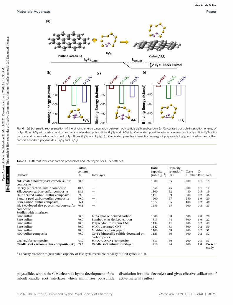
In order to understand the interactions between long-chainlithium polysulfides and the candle soot inbuilt carbon interlayer
(C), first-principles calculations based on density functional theory(DFT) were performed. The schematic (Fig. 6(a)) represents thebinding energy calculation between polysulfide Li2S8 and carbon.The binding energy of carbon with polysulfides Li2S4, Li2S6, andLi2S8 is �78.76, �52.51, and �26.25 kJ mol�1, respectively. Here,we observed promising results in the interaction energies ofcarbon with lithium polysulfides. This indicated the strong inter-layer properties of the carbon-based material (candle soot) towardssoluble polysulfides. The calculated result also demonstratedthat the interaction between the polysulfides and carbon layer isthermodynamically favorable and more stable. Therefore, thecarbon-based candle soot inbuilt interlayer not only acted as aphysical trapper but also chemically anchored higher orderlithium polysulfides.
Further, we investigated the possible interaction of anadsorbed polysulfide carbon layer (e.g., C–Li2S4) with othersoluble polysulfides (e.g., Li2S6 and Li2S8). Fig. 6(b)–(d) repre-sent the calculated possible interaction energies of polysulfidecarbon complexes with other polysulfides and the exact possi-ble set of reactions is shown in eqn (S1) (ESI†). Three cases ofinteractions were considered for each polysulfide. For example,the interaction of the Li2S4 polysulfide can be considered as:
(i) Li2S4 interaction with only the carbon layer, (ii) Li2S4
polysulfide interaction with the Li2S6 polysulfide adsorbedcarbon layer, and (iii) Li2S4 polysulfide interaction with theLi2S8 polysulfide adsorbed carbon layer. Similarly, other inter-actions were considered for the remaining polysulfides Li2S6
and Li2S8.It is interesting to note that the interaction energy of
polysulfide Li2S4 with the bare carbon layer is very low(�78.76 kJ mol�1) compared to that of the polysulfide adsorbedcarbon layer (�315.06 and �262.55 kJ mol�1 for C–Li2S6 andC–Li2S8, respectively). Similar trends are observed with theother polysulfides (Li2S6 and Li2S8). Thus, this computationalstudy thermodynamically proved that the pristine carbon layerpossessed adsorption tendencies with long-chain lithium poly-sulfides. However, the carbon layer with adsorbed polysulfidesacted as a more effective interlayer and can further lower theextent of polysulfide shuttling in Li–S batteries.
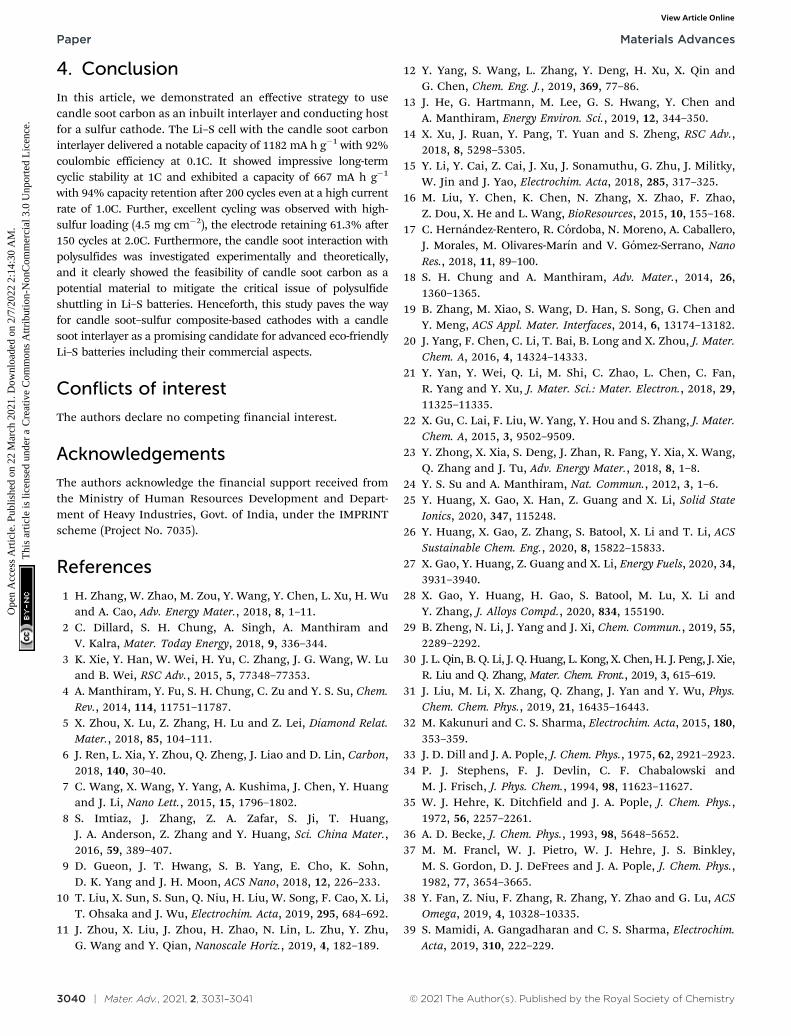
This work demonstrates the excellent stability of the electrodein long-term cycling with interlayer modification and also standsahead in comparison with other forms of carbon–sulfur compo-sites and interlayer modified cells as reported previously, givenin Table 1.
The improvement in the electrochemical performance ismainly attributed to the confinement of higher order
Fig. 5 Electrochemical performance with SC and C-SC high-loading sulfur electrodes. (a) Cyclic voltammogram at a scan rate of 0.1 mV s�1.(b) Galvanostatic charge–discharge profile at 0.1C. (c) Long-term cyclic stability at 2C.
Paper Materials Advances
Ope
n A
cces
s A
rtic
le. P
ublis
hed
on 2
2 M
arch
202
1. D
ownl
oade
d on
2/7
/202
2 2:
14:3
0 A
M.
Thi
s ar
ticle
is li
cens
ed u
nder
a C
reat
ive
Com
mon
s A
ttrib
utio
n-N
onC
omm
erci
al 3
.0 U
npor
ted
Lic
ence
.View Article Online
© 2021 The Author(s). Published by the Royal Society of Chemistry Mater. Adv., 2021, 2, 3031–3041 | 3039
polysulfides within the C-SC electrode by the development of theinbuilt candle soot interlayer which minimizes polysulfide
dissolution into the electrolyte and gives effective utilization ofactive material (sulfur).
Fig. 6 (a) Schematic representation of the binding energy calculation between polysulfide Li2S8 and carbon. (b) Calculated possible interaction energy ofpolysulfide Li2S4 with carbon and other carbon adsorbed polysulfides (Li2S6 and Li2S8). (c) Calculated possible interaction energy of polysulfide Li2S6 withcarbon and other carbon adsorbed polysulfides (Li2S4 and Li2S8). (d) Calculated possible interaction energy of polysulfide Li2S8 with carbon and othercarbon adsorbed polysulfides (Li2S4 and Li2S6).
Table 1 Different low-cost carbon precursors and interlayers for Li–S batteries
Cathode
Sulfurcontent(%) Interlayer
Initialcapacity(mA h g�1)
Capacityretentiona
(%)Cyclenumber
C-Rate Ref.
rGO coated hollow yeast carbon–sulfurcomposite
50.3 — 1000 65 200 0.1 15
Cherry pit carbon–sulfur composite 40.2 — 550 75 200 0.1 17Silk cocoon carbon–sulfur composite 48.4 — 1300 62 80 0.5 19Hair derived carbon–sulfur composite 69.0 — 1113 89 300 0.2 46Banana peel carbon–sulfur composite 60.0 — 600 67 250 1.0 20Fern carbon–sulfur composite 66.4 — 1377 55 100 0.2 48Ni, S co-doped rice popcorn carbon–sulfurcomposite
76.1 — 1256 65 500 0.2 23
Studies with interlayerBare sulfur 60.0 Luffa sponge derived carbon 1000 80 500 2.0 20Bare sulfur 70.0 Bamboo char derived carbon 813 74 300 1.0 22Bare sulfur 70.0 Polyacrylonitrile spun CNF 1134 41 200 0.2 49Bare sulfur 60.0 MoO3 decorated CNF 1142 53 500 0.2 50Bare sulfur 70.0 Modified carbon paper 1100 58 200 0.2 51rGO–sulfur composite 70.0 Co–Fe bimetallic sulfide decorated on
carbon paper1125 56 400 0.2 52
CNT–sulfur composite 75.0 MnO2–GO–CNT composite 813 80 200 0.5 53Candle soot carbon–sulfur composite (SC) 69.3 Candle soot inbuilt interlayer 710 94 200 1.0 Present
study
a Capacity retention = (reversible capacity of last cycle/reversible capacity of first cycle) � 100.
Materials Advances Paper
Ope
n A
cces
s A
rtic
le. P
ublis
hed
on 2
2 M
arch
202
1. D
ownl
oade
d on
2/7
/202
2 2:
14:3
0 A
M.
Thi
s ar
ticle
is li
cens
ed u
nder
a C
reat
ive
Com
mon
s A
ttrib
utio
n-N
onC
omm
erci
al 3
.0 U
npor
ted
Lic
ence
.View Article Online
3040 | Mater. Adv., 2021, 2, 3031–3041 © 2021 The Author(s). Published by the Royal Society of Chemistry
4. Conclusion
In this article, we demonstrated an effective strategy to usecandle soot carbon as an inbuilt interlayer and conducting hostfor a sulfur cathode. The Li–S cell with the candle soot carboninterlayer delivered a notable capacity of 1182 mA h g�1 with 92%coulombic efficiency at 0.1C. It showed impressive long-termcyclic stability at 1C and exhibited a capacity of 667 mA h g�1
with 94% capacity retention after 200 cycles even at a high currentrate of 1.0C. Further, excellent cycling was observed with high-sulfur loading (4.5 mg cm�2), the electrode retaining 61.3% after150 cycles at 2.0C. Furthermore, the candle soot interaction withpolysulfides was investigated experimentally and theoretically,and it clearly showed the feasibility of candle soot carbon as apotential material to mitigate the critical issue of polysulfideshuttling in Li–S batteries. Henceforth, this study paves the wayfor candle soot–sulfur composite-based cathodes with a candlesoot interlayer as a promising candidate for advanced eco-friendlyLi–S batteries including their commercial aspects.
Conflicts of interest
The authors declare no competing financial interest.
Acknowledgements
The authors acknowledge the financial support received fromthe Ministry of Human Resources Development and Depart-ment of Heavy Industries, Govt. of India, under the IMPRINTscheme (Project No. 7035).
References
1 H. Zhang, W. Zhao, M. Zou, Y. Wang, Y. Chen, L. Xu, H. Wuand A. Cao, Adv. Energy Mater., 2018, 8, 1–11.
2 C. Dillard, S. H. Chung, A. Singh, A. Manthiram andV. Kalra, Mater. Today Energy, 2018, 9, 336–344.
3 K. Xie, Y. Han, W. Wei, H. Yu, C. Zhang, J. G. Wang, W. Luand B. Wei, RSC Adv., 2015, 5, 77348–77353.
4 A. Manthiram, Y. Fu, S. H. Chung, C. Zu and Y. S. Su, Chem.Rev., 2014, 114, 11751–11787.
5 X. Zhou, X. Lu, Z. Zhang, H. Lu and Z. Lei, Diamond Relat.Mater., 2018, 85, 104–111.
6 J. Ren, L. Xia, Y. Zhou, Q. Zheng, J. Liao and D. Lin, Carbon,2018, 140, 30–40.
7 C. Wang, X. Wang, Y. Yang, A. Kushima, J. Chen, Y. Huangand J. Li, Nano Lett., 2015, 15, 1796–1802.
8 S. Imtiaz, J. Zhang, Z. A. Zafar, S. Ji, T. Huang,J. A. Anderson, Z. Zhang and Y. Huang, Sci. China Mater.,2016, 59, 389–407.
9 D. Gueon, J. T. Hwang, S. B. Yang, E. Cho, K. Sohn,D. K. Yang and J. H. Moon, ACS Nano, 2018, 12, 226–233.
10 T. Liu, X. Sun, S. Sun, Q. Niu, H. Liu, W. Song, F. Cao, X. Li,T. Ohsaka and J. Wu, Electrochim. Acta, 2019, 295, 684–692.
11 J. Zhou, X. Liu, J. Zhou, H. Zhao, N. Lin, L. Zhu, Y. Zhu,G. Wang and Y. Qian, Nanoscale Horiz., 2019, 4, 182–189.
12 Y. Yang, S. Wang, L. Zhang, Y. Deng, H. Xu, X. Qin andG. Chen, Chem. Eng. J., 2019, 369, 77–86.
13 J. He, G. Hartmann, M. Lee, G. S. Hwang, Y. Chen andA. Manthiram, Energy Environ. Sci., 2019, 12, 344–350.
14 X. Xu, J. Ruan, Y. Pang, T. Yuan and S. Zheng, RSC Adv.,2018, 8, 5298–5305.
15 Y. Li, Y. Cai, Z. Cai, J. Xu, J. Sonamuthu, G. Zhu, J. Militky,W. Jin and J. Yao, Electrochim. Acta, 2018, 285, 317–325.
16 M. Liu, Y. Chen, K. Chen, N. Zhang, X. Zhao, F. Zhao,Z. Dou, X. He and L. Wang, BioResources, 2015, 10, 155–168.
17 C. Hernandez-Rentero, R. Cordoba, N. Moreno, A. Caballero,J. Morales, M. Olivares-Marın and V. Gomez-Serrano, NanoRes., 2018, 11, 89–100.
18 S. H. Chung and A. Manthiram, Adv. Mater., 2014, 26,1360–1365.
19 B. Zhang, M. Xiao, S. Wang, D. Han, S. Song, G. Chen andY. Meng, ACS Appl. Mater. Interfaces, 2014, 6, 13174–13182.
20 J. Yang, F. Chen, C. Li, T. Bai, B. Long and X. Zhou, J. Mater.Chem. A, 2016, 4, 14324–14333.
21 Y. Yan, Y. Wei, Q. Li, M. Shi, C. Zhao, L. Chen, C. Fan,R. Yang and Y. Xu, J. Mater. Sci.: Mater. Electron., 2018, 29,11325–11335.
22 X. Gu, C. Lai, F. Liu, W. Yang, Y. Hou and S. Zhang, J. Mater.Chem. A, 2015, 3, 9502–9509.
23 Y. Zhong, X. Xia, S. Deng, J. Zhan, R. Fang, Y. Xia, X. Wang,Q. Zhang and J. Tu, Adv. Energy Mater., 2018, 8, 1–8.
24 Y. S. Su and A. Manthiram, Nat. Commun., 2012, 3, 1–6.25 Y. Huang, X. Gao, X. Han, Z. Guang and X. Li, Solid State
Ionics, 2020, 347, 115248.26 Y. Huang, X. Gao, Z. Zhang, S. Batool, X. Li and T. Li, ACS
Sustainable Chem. Eng., 2020, 8, 15822–15833.27 X. Gao, Y. Huang, Z. Guang and X. Li, Energy Fuels, 2020, 34,
3931–3940.28 X. Gao, Y. Huang, H. Gao, S. Batool, M. Lu, X. Li and
Y. Zhang, J. Alloys Compd., 2020, 834, 155190.29 B. Zheng, N. Li, J. Yang and J. Xi, Chem. Commun., 2019, 55,
2289–2292.30 J. L. Qin, B. Q. Li, J. Q. Huang, L. Kong, X. Chen, H. J. Peng, J. Xie,
R. Liu and Q. Zhang, Mater. Chem. Front., 2019, 3, 615–619.31 J. Liu, M. Li, X. Zhang, Q. Zhang, J. Yan and Y. Wu, Phys.
Chem. Chem. Phys., 2019, 21, 16435–16443.32 M. Kakunuri and C. S. Sharma, Electrochim. Acta, 2015, 180,
353–359.33 J. D. Dill and J. A. Pople, J. Chem. Phys., 1975, 62, 2921–2923.34 P. J. Stephens, F. J. Devlin, C. F. Chabalowski and
M. J. Frisch, J. Phys. Chem., 1994, 98, 11623–11627.35 W. J. Hehre, K. Ditchfield and J. A. Pople, J. Chem. Phys.,
1972, 56, 2257–2261.36 A. D. Becke, J. Chem. Phys., 1993, 98, 5648–5652.37 M. M. Francl, W. J. Pietro, W. J. Hehre, J. S. Binkley,
M. S. Gordon, D. J. DeFrees and J. A. Pople, J. Chem. Phys.,1982, 77, 3654–3665.
38 Y. Fan, Z. Niu, F. Zhang, R. Zhang, Y. Zhao and G. Lu, ACSOmega, 2019, 4, 10328–10335.
39 S. Mamidi, A. Gangadharan and C. S. Sharma, Electrochim.Acta, 2019, 310, 222–229.
Paper Materials Advances
Ope
n A
cces
s A
rtic
le. P
ublis
hed
on 2
2 M
arch
202
1. D
ownl
oade
d on
2/7
/202
2 2:
14:3
0 A
M.
Thi
s ar
ticle
is li
cens
ed u
nder
a C
reat
ive
Com
mon
s A
ttrib
utio
n-N
onC
omm
erci
al 3
.0 U
npor
ted
Lic
ence
.View Article Online
© 2021 The Author(s). Published by the Royal Society of Chemistry Mater. Adv., 2021, 2, 3031–3041 | 3041
40 M. Kakunuri, S. Vennamalla and C. S. Sharma, RSC Adv.,2015, 5, 4747–4753.
41 X. Ma, G. Ning, Y. Wang, X. Song, Z. Xiao, L. Hou, W. Yang,J. Gao and Y. Li, Electrochim. Acta, 2018, 269, 83–92.
42 G. Ananya, S. Raghu and S. Ramaprabhu, J. Mater. Chem. A,2017, 5, 2784–2791.
43 M. Kakunuri, S. Kaushik, A. Saini and C. S. Sharma, Bull.Mater. Sci., 2017, 40, 435–439.
44 M. Kruk and M. Jaroniec, Chem. Mater., 2001, 13,3169–3183.
45 S. Li, X. Chen, F. Hu, R. Zeng, Y. Huang, L. Yuan and J. Xie,Electrochim. Acta, 2019, 304, 11–19.
46 M. Yu, R. Li, Y. Tong, Y. Li, C. Li, J. D. Hong and G. Shi,J. Mater. Chem. A, 2015, 3, 9609–9615.
47 J. Q. Huang, Q. Zhang, S. M. Zhang, X. F. Liu, W. Zhu,W. Z. Qian and F. Wei, Carbon, 2013, 58, 99–106.
48 X. Long You, L. Jun Liu, M. Yuan Zhang, M. D. Walle, Y. Liand Y. N. Liu, Mater. Lett., 2018, 217, 167–170.
49 M. Yanilmaz, A. M. Asiri and X. Zhang, J. Mater. Sci., 2020,55, 3538–3548.
50 H. Li, X. Wang, C. Qi, C. Zhao, C. Fu, L. Wang and T. Liu,Phys. Chem. Chem. Phys., 2020, 22, 2157–2163.
51 Y. Li, L. Ming, L. Jin, L. Yun and H. Jian, Mater. Res. Express,2019, 6, 125547.
52 Y. Huang, D. Lv, Z. Zhang, Y. Ding, F. Lai, Q. Wu, H. Wang,Q. Li, Y. Cai and Z. Ma, Chem. Eng. J., 2020, 387, 124122.
53 W. Kong, L. Yan, Y. Luo, D. Wang, K. Jiang, Q. Li, S. Fan andJ. Wang, Adv. Funct. Mater., 2017, 27, 1606663.
Materials Advances Paper
Ope
n A
cces
s A
rtic
le. P
ublis
hed
on 2
2 M
arch
202
1. D
ownl
oade
d on
2/7
/202
2 2:
14:3
0 A
M.
Thi
s ar
ticle
is li
cens
ed u
nder
a C
reat
ive
Com
mon
s A
ttrib
utio
n-N
onC
omm
erci
al 3
.0 U
npor
ted
Lic
ence
.View Article Online