Embed Size (px)
Citation preview
PROTECTION RELAY FOR SHAFT CURRENT AND VOLTAGE
A., Elez, I., Poljak, J., PolakKONČAR – Electrical Engineering Institute Inc.
Croatia
J., ŠtudirKONČAR – Generators and Motors Inc.
Croatia
M., Dujmović HEP – Production
Croatia
INTRODUCTION
The paper deals with the specific protection relay for all types of generators. Theinstrument, called Shaft Current and Voltage Protection Relay (SCVP) wasdeveloped at KONCAR – Electric Engineering Institute Inc. This instrument is a partof Institute's product line used for monitoring and diagnosis of rotating electricalmachines.
The most important parts of every electric power system are electrical rotatingmachines, especially those involved in the production of electrical energy.Nowadays, electrical rotating machines must fulfill more complex requirements ofelectrical power system which are constantly increasing and at the same time theproduction of electrical energy must be optimized. On the other hand, long lifetimeand increased reliability of the machines is expected. Various monitoring andprotection systems represent solutions for owners of expensive electricalmachines and they can enable better asset management. This can prolong thelifetime of the machines and reduce costs caused by unplanned downtimes andunnecessary maintenance.
Problems that can occur in electrical machines are shaft currents and voltages. Dueto the asymmetry of the magnetic field in the machine, a voltage in the shaft can beinduced, which, depending on the type of machine, its size and load, varies inamplitude and frequency composition. Low impedance of the circuit consisting ofshaft, bearing, oil film and other structural components, can cause shaft currentflow which leads to bearing destruction.

Continuous measurement and analysis of shaft currents and voltages can preventmajor faults. Through detailed processing of the measured data the causes ofoccurrence of shaft currents and voltages can be identified. The main purpose ofSCVP system is to detect shaft currents and voltages that may damage thegenerator bearing, and thus prevent greater economic damages.
The aim of this paper is to show how data obtained by SCVP system can extend thelife-time of the machine and provide manufacturers and users of the machineinsight to useful information during machine work period that can help in betterasset management.
1. BACKGROUND AND MOTIVATION
Nowadays, modern life is not possible without stable, uninterruptable supply ofelectric energy that is needed both in industry and in our private lives. Accordingto its importance, electric power system has to be maintained and protectedagainst possible faults and constant increase of the reliability and availability ofrotating electrical machines is of utmost importance. Current practice in electricalpower system is to extend periods between planned outages of the machines. Anymalfunctions, unnecessary and unplanned outages can cause extensive materialdamage. The way to alleviate or even prevent such events is implementation ofvarious modes of rotating machines monitoring and protection systems.
One of the problems that can occur in the generator relates to shaft currents andvoltages. Due to the design and construction parameters of the generator, and dueto the electrical and magnetic characteristics of the generator in operation aphenomena called shaft current can occur. The main reason for occurrence of shaftcurrents is magnetic field asymmetry in the generator. These asymmetries cancause a potential difference between two points on the shaft which leads to shaftvoltage and thus eventually shaft current flow.
Bearing insulation and insulation stability of the bearing oil film can deteriorate intime. This can decrease the impedance of the circuit consisting of shaft, bearing, oilfilm and other structural components. Reduced impedance leads to current flowthrough the bearing and this current flow can cause serious damage to the bearingand thus jeopardize the proper and reliable work of the generator. Generatordamage resulting from shaft currents depends on amplitude and duration ofcurrent flow. For larger generators currents less than 1A should not cause greaterdamage. However, by monitoring even less currents in certain time period it can beconcluded that eventually problems regarding shaft current flow might occur.
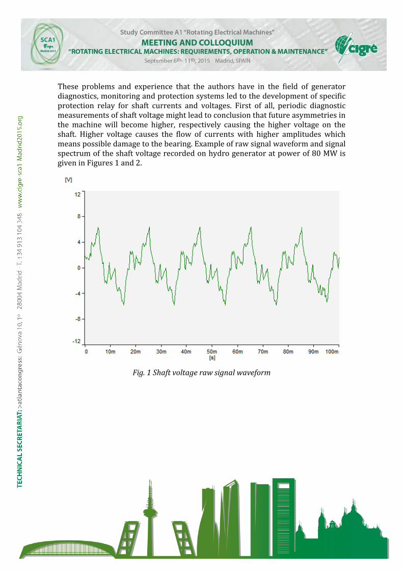
These problems and experience that the authors have in the field of generatordiagnostics, monitoring and protection systems led to the development of specificprotection relay for shaft currents and voltages. First of all, periodic diagnosticmeasurements of shaft voltage might lead to conclusion that future asymmetries inthe machine will become higher, respectively causing the higher voltage on theshaft. Higher voltage causes the flow of currents with higher amplitudes whichmeans possible damage to the bearing. Example of raw signal waveform and signalspectrum of the shaft voltage recorded on hydro generator at power of 80 MW isgiven in Figures 1 and 2.
Fig. 1 Shaft voltage raw signal waveform
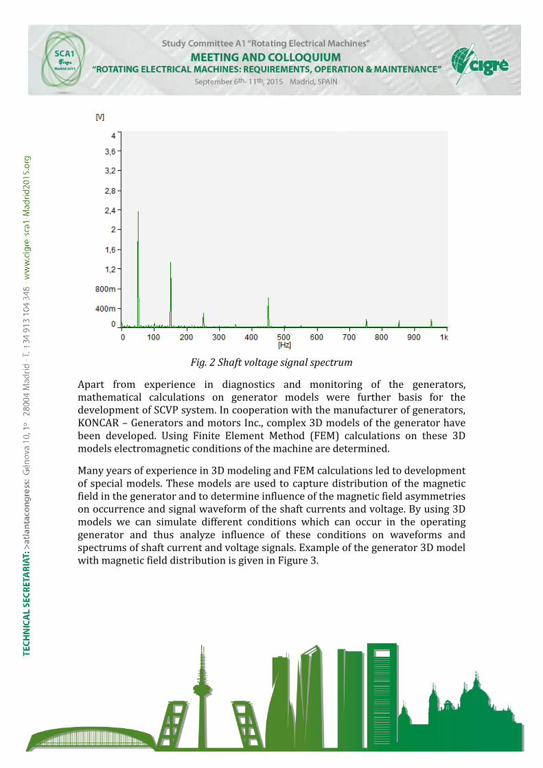
Fig. 2 Shaft voltage signal spectrum
Apart from experience in diagnostics and monitoring of the generators,mathematical calculations on generator models were further basis for thedevelopment of SCVP system. In cooperation with the manufacturer of generators,KONCAR – Generators and motors Inc., complex 3D models of the generator havebeen developed. Using Finite Element Method (FEM) calculations on these 3Dmodels electromagnetic conditions of the machine are determined.
Many years of experience in 3D modeling and FEM calculations led to developmentof special models. These models are used to capture distribution of the magneticfield in the generator and to determine influence of the magnetic field asymmetrieson occurrence and signal waveform of the shaft currents and voltage. By using 3Dmodels we can simulate different conditions which can occur in the operatinggenerator and thus analyze influence of these conditions on waveforms andspectrums of shaft current and voltage signals. Example of the generator 3D modelwith magnetic field distribution is given in Figure 3.
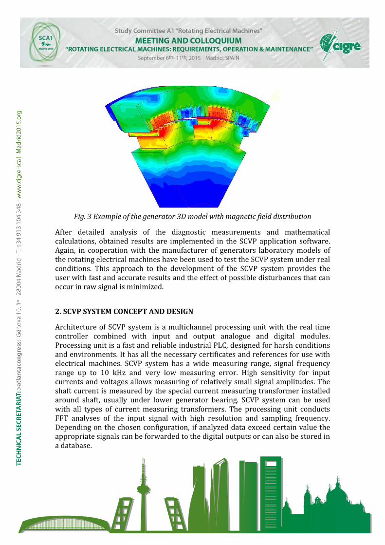
Fig. 3 Example of the generator 3D model with magnetic field distribution
After detailed analysis of the diagnostic measurements and mathematicalcalculations, obtained results are implemented in the SCVP application software.Again, in cooperation with the manufacturer of generators laboratory models ofthe rotating electrical machines have been used to test the SCVP system under realconditions. This approach to the development of the SCVP system provides theuser with fast and accurate results and the effect of possible disturbances that canoccur in raw signal is minimized.
2. SCVP SYSTEM CONCEPT AND DESIGN
Architecture of SCVP system is a multichannel processing unit with the real timecontroller combined with input and output analogue and digital modules.Processing unit is a fast and reliable industrial PLC, designed for harsh conditionsand environments. It has all the necessary certificates and references for use withelectrical machines. SCVP system has a wide measuring range, signal frequencyrange up to 10 kHz and very low measuring error. High sensitivity for inputcurrents and voltages allows measuring of relatively small signal amplitudes. Theshaft current is measured by the special current measuring transformer installedaround shaft, usually under lower generator bearing. SCVP system can be usedwith all types of current measuring transformers. The processing unit conductsFFT analyses of the input signal with high resolution and sampling frequency.Depending on the chosen configuration, if analyzed data exceed certain value theappropriate signals can be forwarded to the digital outputs or can also be stored ina database.
After the FFT analysis the processing unit monitors the amplitude of specific signalharmonics. Basic configuration enables digital relay outputs that can be forwardedto generator protection or SCADA systems. If the amplitude of the chosen signalharmonic exceeds threshold setting digital relay is activated. Usually two digitaloutputs are needed. One is the alarm which represents first threshold with onlywarning function. The other output is danger output which is usually connected tothe protection system and it is used to turn of the generator if it exceeds the pre-set value.
Initial limits of alarm and danger outputs are defined based on years of experience.Mentioned mathematical calculations also can be helpful in determining theseinitial limits. It is important to protect the generator from possible damage, butalso to avoid false shutdowns of the generator.
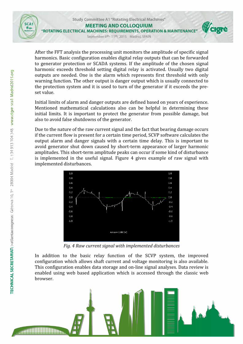
Due to the nature of the raw current signal and the fact that bearing damage occursif the current flow is present for a certain time period, SCVP software calculates theoutput alarm and danger signals with a certain time delay. This is important toavoid generator shut down caused by short-term appearance of larger harmonicamplitudes. This short-term amplitude peaks can occur if some kind of disturbanceis implemented in the useful signal. Figure 4 gives example of raw signal withimplemented disturbances.
Fig. 4 Raw current signal with implemented disturbances
In addition to the basic relay function of the SCVP system, the improvedconfiguration which allows shaft current and voltage monitoring is also available.This configuration enables data storage and on-line signal analyses. Data review isenabled using web based application which is accessed through the classic webbrowser.
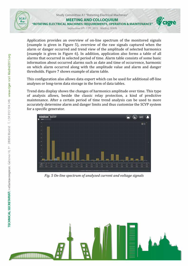
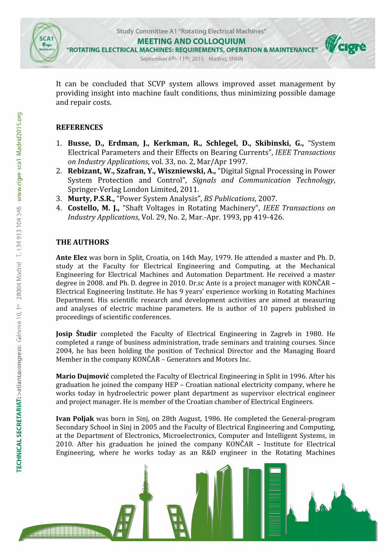
Application provides an overview of on-line spectrum of the monitored signals(example is given in Figure 5), overview of the raw signals captured when thealarm or danger occurred and trend view of the amplitude of selected harmonics(example is given in Figure 6). In addition, application also forms a table of allalarms that occurred in selected period of time. Alarm table consists of some basicinformation about occurred alarms such as date and time of occurrence, harmonicon which alarm occurred along with the amplitude value and alarm and dangerthresholds. Figure 7 shows example of alarm table.
This configuration also allows data export which can be used for additional off-lineanalyses or long-term data storage in the form of data tables.
Trend data display shows the changes of harmonics amplitude over time. This typeof analysis allows, beside the classic relay protection, a kind of predictivemaintenance. After a certain period of time trend analysis can be used to moreaccurately determine alarm and danger limits and thus customize the SCVP systemfor a specific generator.
Fig. 5 On-line spectrum of analyzed current and voltage signals
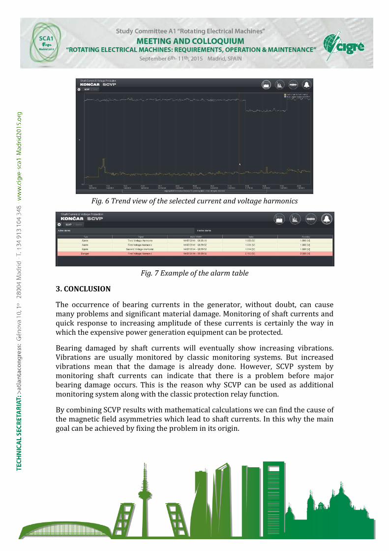
Fig. 6 Trend view of the selected current and voltage harmonics
Fig. 7 Example of the alarm table
3. CONCLUSION
The occurrence of bearing currents in the generator, without doubt, can causemany problems and significant material damage. Monitoring of shaft currents andquick response to increasing amplitude of these currents is certainly the way inwhich the expensive power generation equipment can be protected.
Bearing damaged by shaft currents will eventually show increasing vibrations.Vibrations are usually monitored by classic monitoring systems. But increasedvibrations mean that the damage is already done. However, SCVP system bymonitoring shaft currents can indicate that there is a problem before majorbearing damage occurs. This is the reason why SCVP can be used as additionalmonitoring system along with the classic protection relay function.
By combining SCVP results with mathematical calculations we can find the cause ofthe magnetic field asymmetries which lead to shaft currents. In this why the maingoal can be achieved by fixing the problem in its origin.
It can be concluded that SCVP system allows improved asset management byproviding insight into machine fault conditions, thus minimizing possible damageand repair costs.
REFERENCES
1. Busse, D., Erdman, J., Kerkman, R., Schlegel, D., Skibinski, G., “SystemElectrical Parameters and their Effects on Bearing Currents”, IEEE Transactionson Industry Applications, vol. 33, no. 2, Mar/Apr 1997.
2. Rebizant, W., Szafran, Y., Wiszniewski, A., “Digital Signal Processing in PowerSystem Protection and Control”, Signals and Communication Technology,Springer-Verlag London Limited, 2011.
3. Murty, P.S.R., “Power System Analysis”, BS Publications, 2007.4. Costello, M. J., “Shaft Voltages in Rotating Machinery”, IEEE Transactions on
Industry Applications, Vol. 29, No. 2, Mar.-Apr. 1993, pp 419-426.
THE AUTHORS
Ante Elez was born in Split, Croatia, on 14th May, 1979. He attended a master and Ph. D.study at the Faculty for Electrical Engineering and Computing, at the MechanicalEngineering for Electrical Machines and Automation Department. He received a masterdegree in 2008. and Ph. D. degree in 2010. Dr.sc Ante is a project manager with KONČAR – Electrical Engineering Institute. He has 9 years’ experience working in Rotating MachinesDepartment. His scientific research and development activities are aimed at measuringand analyses of electric machine parameters. He is author of 10 papers published inproceedings of scientific conferences.
Josip Študir completed the Faculty of Electrical Engineering in Zagreb in 1980. Hecompleted a range of business administration, trade seminars and training courses. Since2004, he has been holding the position of Technical Director and the Managing BoardMember in the company KONČAR – Generators and Motors Inc.
Mario Dujmović completed the Faculty of Electrical Engineering in Split in 1996. After hisgraduation he joined the company HEP – Croatian national electricity company, where heworks today in hydroelectric power plant department as supervisor electrical engineerand project manager. He is member of the Croatian chamber of Electrical Engineers.
Ivan Poljak was born in Sinj, on 28th August, 1986. He completed the General-programSecondary School in Sinj in 2005 and the Faculty of Electrical Engineering and Computing,at the Department of Electronics, Microelectronics, Computer and Intelligent Systems, in2010. After his graduation he joined the company KONČAR – Institute for Electrical Engineering, where he works today as an R&D engineer in the Rotating Machines

Department. His scientific research and development activities are part of the electricalmachines diagnostics and monitoring area. He is author of several papers published inproceedings of scientific conferences.
Josip Polak was born in Zagreb, Croatia in 1950. He completed the Faculty of ElectricalEngineering in Zagreb in 1973. After his graduation he joined the company KONČAR – Institute for Electrical Engineering, where he works today as a member of the RotatingMachines Department. He published more than 70 scientific and expert papers andstudies.