Embed Size (px)
Citation preview

Page 1
(SE970118)
(SE970139)
Thermal overcurrent relay and protection assemblies
RXVK 2H andRAVK
1MRK 509 003-BEN
Issued January 2004Revision: A
Data subject to change without notice
Features • Thermal overcurrent relay with the same time constants for heating and cooling.
• For protection of motors, generators, trans-formers, cables and filter reactors.
• Micro-processor based thermal overcurrent relay with continuous settings for time and instantaneous functions.
• Two variants with wide setting ranges:
- Scale constant Is = 0,1, 0,2, 0,4, 1,0 A or 0,5, 1,0, 2,0, 5,0 A
- Thermal basic currentIb = (0,5-1,5) x Is
- Overcurrent operate current I > (0,5-20) x Is
• Thermal time constant programmable 2-62 min in steps of 2 min with the same time constants for heating and cooling.
• Available with optional filter for suppressing frequency dependence 40-2000 Hz
• Relay contacts for Θ > 95% of trip tempera-ture, thermal trip and overcurrent trip.
• Indications for thermal and overcurrent trip, Θ > 95% and in service.
• Overcurrent operation can be delayed up to 5 s for fuse selectivity.
• Binary input; reconnectible for reset LED or reset LED and thermal value.
• Reset ratio typical 95% enables a setting close to maximum service values.
• Recovery time < 40 ms enables small time steps between time selective protection.
• Low transient overreach i.e. the relay is insensitive to dc component in fault current.

Thermal overcurrent relay and protection assemblies
RXVK 2H and RAVK1MRK 509 003-BEN
Page 2
Application When load currents exceed the permitted con-tinuous current there is an imminent risk that conductors and insulation will be damaged due to overheating. RXVK 2H thermal over-current relay effectively prevents such dam-age and, at the same time, allow full utilization of the protected object.
Time constants from 2 min to 62 min can be selected in steps of 2 min. The thermal time constant, τ, is defined as the time required by the protected object to reach 63% of the steady-state temperature, Θ, when the object in question is supplied with a constant current, see Fig. 1.
The relay is provided with LEDs for indica-tion in service, Θ > 95% of trip temperature, thermal trip and overcurrent trip.
Fig. 1 Definition of thermal time constant.
Design The thermal overcurrent relay assemblies with RXVK 2H are available in several vari-ants for single-phase, two-phase and three-phase overcurrent protection with different output circuits. The trip indication is hand reset.
A short-circuiting connector, type RTXK, is delivered with each relay. This connector is mounted on the rear of the terminal base and will automatically short-circuit current input when the relay is removed from the terminal base.
The RXVK 2H relay require a separate dc-dc converter for auxiliary supply (±24 V). One RXTUG converter can supply up to nine relays.
Note:When the RXVH 2H relay or the dc-dc con-verter RXTUG is plugged into or withdrawn from a terminal base, the auxiliary voltage supply must be interrupted. Neither is it allowed to open wiring on plus or minus sup-ply with the unit in service.
RXVK 2H measuring relayThe thermal overcurrent relay, type RXVK 2H, is a static microprocessor based relay with a thermal stage and a definite time delayed overcurrent stage. The relay consists mainly of an input current transformer (for isolation), filter circuits, microprocessor, HMI, LEDs for start and trip indications and
three output units which provide separate change-over contacts for thermal and over-current trips and Θ > 95%. The relay has also one binary input with opto-coupler for exter-nal reset of LED or reset of thermal value and LED.
The current for the thermal stage is set on the scale marked Ib. Operation occurs for a cur-rent equal to or larger than the product of set scale value and the selected scale constant (Is) times 1,01 (constant K). The scale constant is selected by dip switches on the front of the relay.
The Θ > 95% output immediately after the measured thermal content exceeds 95% of thermal trip temperature.
The thermal trip will depend of the set time (thermal time constant), and by how much the measured current exceeds set basic the cur-rent.
The overcurrent stage I> operates when the current exceeds the set value. The function can be delayed up to 5 s.
All current and time settings are settable with a programming switch with potentiometers on the front.
The relay is available with optional filter for suppressing frequency dependence 40-2000 Hz.
Rise of temperature
Θ
0,63Θ
Timeτ (960
0025
6)

Thermal overcurrent relay and protection assemblies
RXVK 2H and RAVK1MRK 509 003-BEN
Page 3
Technical dataTable 1: Current input
Rated current Ir 1 or 5 A
Scale constant Is (0,1/0,2/0,4 and 1,0) x Ir
Scale range1 A Variant
IbI>
5 A VariantIbI>
0,05-1,5 A0,05-20 A and ∞
0,25-7,5 A0,25-100 A and ∞
Effective current range (0,75-65) x Is
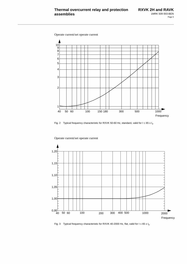
Rated frequency frFrequency characteristics
Frequency range
50-60 HzFilter options:
50-60 Hz, flat (standard variant), see Fig. 240-2000 Hz, flat, see Fig. 3
40-2000 Hz
Power consumption 1 A variant
I = Is = 0,1 AI = Is = 1 A
5 A variantI = Is = 0,5 AI = Is = 5 A
0,5 mVA50 mVA
1 mVA100 mVA
Over load capacity1 A variant
continuouslyduring 1 s
5 A variantcontinuouslyduring 1 s
4 A100 A
20 A350 A

Thermal overcurrent relay and protection assemblies
RXVK 2H and RAVK1MRK 509 003-BEN
Page 4
Technical data (cont’d)Technical data (cont’d)Table 2: Thermal function
Thermal content Q
Operate current k x Ib
Constant k 1,01
Basic current Ib Settable (0,5-1,5) x Is
Alarm level 95% of Θ for trip operation
Operating range (0-8) x Ib
Thermal time constant τ 2-62 min, settable in steps of 2 min
Operate time Equation according to IEC 255-8,1990
t = operate timek = constant = 1,01Ip = load current before the overload occursIb = set basic currentτ = set thermal time constant
Accuracy on the operate value I= ± 1%k = ± 0,01t= ± (ttheoretical x 0,01 + 50 ms)
Reset valueAlarmTrip
Consistency
Θ < 95 %Θ < 80 %< 0,5 %
Influence of harmonics:100/120 Hz, 10%150/180 Hz, 10%250/300 Hz, 10%
< 3%< 3%< 3%
Table 3: Over-current function
RXVK 2H 50-60 Hz, standard filter 40-2000 Hz, flat filter
Setting range I > (0,5-20) x Is or ∞
Setting range for time delayAccuracy
0,03-5 s1% and ±10 ms
Operate time (typical)I = 0 => 1,3 x I> I = 0 => 3 x I> I = 0 => 10 x I>
Time delay = 0,03 s35 ms25 ms20 ms
Reset time (typical)I = 3 => 0 x I> I = 20 => 0 x I>
35 ms60 ms
Reset ratio (typical)Consistency
95%< 1,5%
Transient over-reach L/R=10,50 and 100 ms < 5 % < 20 %
Operate value at 150 Hz App. 1,5 x set op. value –
Operate value within the range40-2000 Hz – < 1,1 x set op. value
Overshoot time < 20 ms
Recovery time at I = 3 x I> < 40 ms
Influence of harmonics:100/120 Hz, 10%150/180 Hz, 10%250/300 Hz, 10%
< 3%< 3%< 3%
–––
t τI2
Ip2
–
I2
Ib2
k2⋅–
---------------------------ln⋅=
Thermal overcurrent relay and protection assemblies
RXVK 2H and RAVK1MRK 509 003-BEN
Page 5
Operate current/set operate current
Fig. 2 Typical frequency characteristic for RXVK 50-60 Hz, standard, valid for I ≤ 65 x Is.
Operate current/set operate current
Fig. 3 Typical frequency characteristic for RXVK 40-2000 Hz, flat, valid for I ≤ 65 x Is.
1
2
10
3
40 50 60 100 1000300 500150 180
4
5
6
789
Frequency
1,00
1,05
40 50 60 100 2000500 1000200 3000,95
1,10
1,20
400
1,15
Frequency

Thermal overcurrent relay and protection assemblies
RXVK 2H and RAVK1MRK 509 003-BEN
Page 6
Technical data (cont’d)Technical data (cont’d)Table 4: Auxiliary DC voltage supply
Auxiliary voltage EL for RXTUG 22HAuxiliary voltage to the relay
24-250 V DC, ±20%±24 V (from RXTUG 22H)
Power consumption at RXTUG 22H input24-250 V
before operation after operation
without RXTUG 22H±24 V
before operation after operation
Standard other filter
Max. 4,5 W Max. 5,5 WMax. 6,0 W Max. 6,5 W
Max. 1,3 W Max. 2,0 WMax. 3,0 W Max. 3,0 W
Table 5: Binary input
Binary input voltage RL 48-60 V and 110-220 V DC, -20% to +10%
Power consumption48-60 V110-220 V
Max. 0,3 WMax. 1,5 W
Table 6: Output relays
Contacts 3 change-over
Maximum system voltage 250 V AC / DC.
Current carrying capacitycontinuousduring 1 s
5 A15 A
Making capacity at inductive load with L/R >10 msduring 200 msduring 1 s
30 A10 A
Breaking capacityAC, max. 250 V, cos ϕ > 0,4DC, with L/R < 40 ms
48 V110 V220 V250 V
8 A
1 A0,4 A0,2 A0,15 A
Table 7: Electromagnetic disturbance tests
All tests are done together with the DC/DC-converter, RXTUG 22H
Test Severity Standard
Surge immunity test 1 and 2 kV, normal service2 and 4 kV, destructive test
IEC 61000-4-5, class 3IEC 61000-4-5, class 4
AC injection test 500 V, AC SS 436 15 03, PL 4
Power frequency field immunity test 1000 A/m IEC 61000-4-8
1 MHz burst test 2,5 kV IEC 60255-22-1, class 3
Spark test 4-8 kV SS 436 15 03, PL 4
Fast transient test 4 kV IEC 60255-22-4, class 4
Electrostatic discharge testIn normal service with cover on 8 kV (contact)
15 kV (air)8 kV, indirect application
IEC 60255-22-2, class 4IEC 60255-22-2, class 4IEC 61000-4-2, class 4
Radiated electromagnetic field test 10 V/m, 26-1000 MHz IEC 61000-4-3, level 3
Conducted electromagnetic test 10 V, 0,15-80 MHz IEC 61000-4-6, level 3
Interruptions in auxiliary voltage 110 VDC, no resetting for interruptions
2-200 ms< 40 ms
IEC 60255-11

Thermal overcurrent relay and protection assemblies
RXVK 2H and RAVK1MRK 509 003-BEN
Page 7
Diagrams
Fig. 4 Terminal diagram RXVK 2H.
Table 8: Electromagnetic emission tests
Test Severity Standard
Conducted 0,15-30 MHz, class A EN 50081- 2
Radiated emission 30-1000 MHz, class A EN 50081- 2
Table 9: Insulation tests
Test Severity Standard
Dielectric testcurrent circuitother circuitsover open contact
2,5 kV AC, 1 min2,0 kV AC, 1 min1,0 kV AC, 1 min
IEC 60255-5
Impulse voltage test 5 kV, 1,2/50 µs, 0,5 J IEC 60255-5
Insulation resistance > 100 MΩ at 500 V DC IEC 60255-5
Table 10: Mechanical tests
Test Severity Standard
Vibration Response: 2,0 g, 10-150-10 HzEndurance:1,0 g, 10-150-10 Hz, 20 sweeps
IEC 60255-21-1, class 2IEC 60255-21-1, class 1
Shock Response: 5 g, 11 ms, 3 pulsesWithstand: 15 g, 11 ms, 3 pulses
IEC 60255-21-2, class 1
Bump Withstand: 10 g, 16 ms, 1000 pulses IEC 60255-21-2, class 1
Seismic X axis: 3,0 g, 1-35-1 HzY axis: 3,0 g, 1-35-1 HzZ axis: 2,0 g, 1-35-1 Hz
IEC 60255-21-3, class 2, extended(Method A)
Table 11: Temperature range
Storage -20 °C to +70 °C
Permitted ambient temperature -5 °C to +55 °C
Table 12: Weight and dimensions
Equipment Weight Height Width
RXVK 2H without RXTUG 22H 0,7 kg 4U 6C
(960
0025
9)

Thermal overcurrent relay and protection assemblies
RXVK 2H and RAVK1MRK 509 003-BEN
Page 8
Diagrams (cont’d)Diagrams (cont’d)
Fig. 5 Terminal diagram 1MRK 001 018-EAA
Fig. 6 Terminal diagram 1MRK 001 018-ZAA

Thermal overcurrent relay and protection assemblies
RXVK 2H and RAVK1MRK 509 003-BEN
Page 9
Protectionassemblies
RAVK Protection assemblies are built up based upon time thermal overcurrent relay RXVK 2H. Test device RXTP 18 and dc/dc-converter RXTUG 22H can also be included for specific application requirements. Test device RTXP 18 is a tool for relay testing.
DC/DC-converter RXTUG 22H can be used either separately for a single protection or to feed also other protections with up to 9 units of the same relay family. With RXTUG 22H all requirements concerning disturbance emission and immunity with this protection assembly will be met.
The assemblies have output contacts as speci-fied for the relay RXVK 2H, which in most cases are fully sufficient.
Protections are normally available with out-put logic with heavy duty relay RXME 18 (RK 221 825-XX) with indicating flag and can upon request be completed with an output logic of free choice. Output relays are con-nected to separate auxiliary voltage.
The extremely flexible mounting system COMBIFLEX together with a modern CAD-system enables us to present a unique flexi-bility for designing assemblies upon the cus-tomers requests.
The interface voltage for enable or block impulses can be connected to either 48-60 V dc or 110-220 V dc by connecting the voltage circuit to separate terminals. At delivery all relays are connected for 110-220 V dc.
RAVK 1 Single-phase thermal overcurrent protection
101RTXP 18 101RXTUG 22H 101RTXP 18 101RTXP 18
107RXVK 2H 107RXVK 2H 107RXTUG 22H 107RXTUG 22H
113RXVK 2H 113RXVK 2H
119RXME 18
319RXME 18
Order No. Circuitdiagram
Order No. Circuitdiagram
Order No. Circuitdiagram
Order No. Circuitdiagram
Standard 1MRK001 017-BS
1MRK001 018-BA
1MRK001 017-CS
1MRK001 018-CA
1MRK001 017-DS
1MRK001 018-DA
1MRK001 017-ES
1MRK001 018-EA
Filter 1MRK001 017-BA
1MRK001 018-BA
1MRK001 017-CA
1MRK001 018-CA
1MRK001 017-DA
1MRK001 018-DA
1MRK001 017-EA
1MRK001 018-EA
1=> 0
49 107101 107101 113107101
319
119113107101

Thermal overcurrent relay and protection assemblies
RXVK 2H and RAVK1MRK 509 003-BEN
Page 10
Mountingalternatives
All assemblies can be delivered in the follow-ing mounting alternatives:
- on apparatus bars (standard)
- in equipment frame 60C
- in RHGS
- in RHGX
Ordering Specify RAVK (Protection):
• Quantity
• Ordering number
• Code A, H, M
• Desired wording on the lower half of the test switch face plate max. 13 lines with 14 characters per line.
Specify RXVK (Loose relay):
• Quantity
• Ordering number
Thermal overcurrent relay, standard 50-60 Hz (flat)
Thermal overcurrent relay, filter 40-2000 Hz (flat)
RAVK 3 Three-phase thermal overcurrent protection
101RTXP 18 101RXTUG 22H 101RTXP 18 101RTXP 18
107RXVK 2H 107RXVK 2H 107RXTUG 22H 107RXTUG 22H
113RXVK 2H 113RXVK 2H 113RXVK 2H 113RXVK 2H
119RXVK 2H 119RXVK 2H 119RXVK 2H 119RXVK 2H
125RXVK 2H 125RXVK 2H
131RXME 18
331RXME 18
Order No. Circuitdiagram
Order No. Circuitdiagram
Order No. Circuitdiagram
Order No. Circuitdiagram
Standard 1MRK001 017-NS
1MRK001 018-NA
1MRK001 017-YS
1MRK001 018-YA
1MRK001 017-PS
1MRK001 018-PA
1MRK001 017-ZU
1MRK001 018-ZA
Filter 1MRK001 017-NA
1MRK001 018-NA
1MRK001 017-YA
1MRK001 018-YA
1MRK001 017-PA
1MRK001 018-PA
1MRK001 017-ZA
1MRK001 018-ZA
1=> 0
49
3107101 113 119 107101 113 119 113107101 119 125
331
131107101 113 119 125
Type Rated current Filter Article No. Code
RXVK 2H 1 A 50-60 Hz (flat) 1MRK 000 840-AA A1
RXVK 2H 5 A 50-60 Hz (flat) 1MRK 000 840-HA A6
Type Rated current Filter Article No. Code
RXVK 2H 1 A 40-2000 Hz (flat) 1MRK 000 840-DA A4
RXVK 2H 5 A 40-2000 Hz (flat) 1MRK 000 840-MA A9
Thermal overcurrent relay and protection assemblies
RXVK 2H and RAVK1MRK 509 003-BEN
Page 11
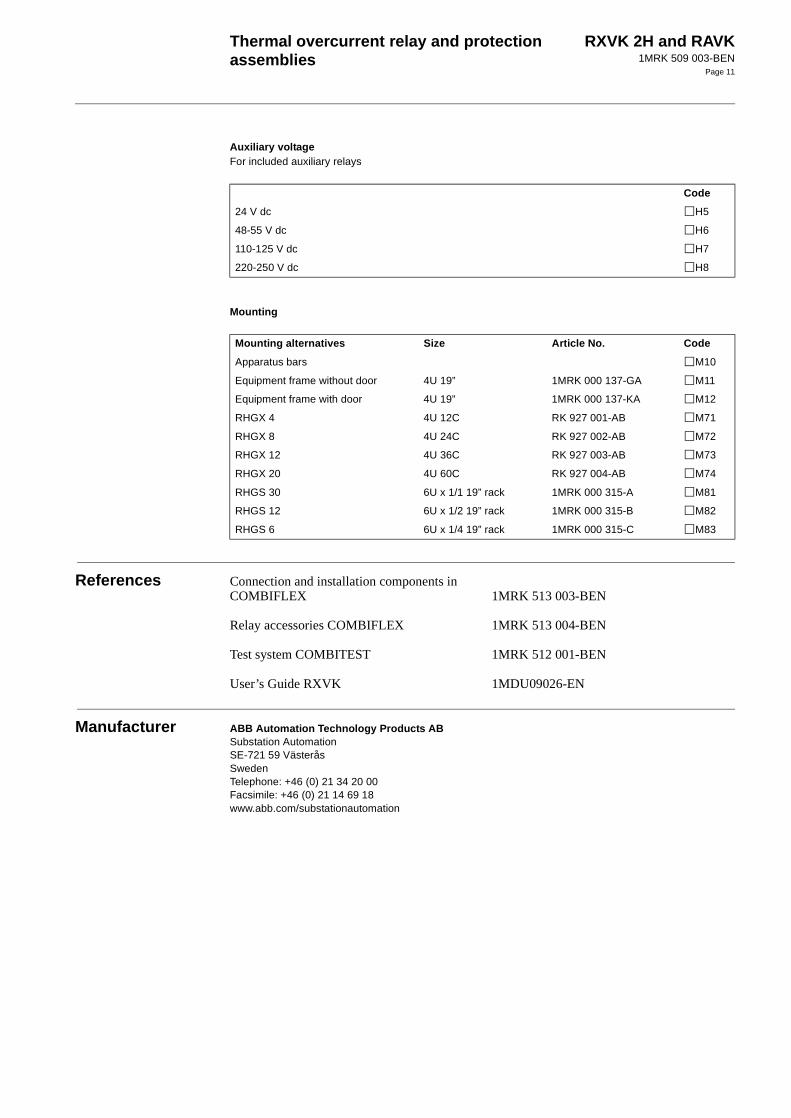
Auxiliary voltageFor included auxiliary relays
Mounting
References Connection and installation components in COMBIFLEX
Relay accessories COMBIFLEX
Test system COMBITEST
User’s Guide RXVK
1MRK 513 003-BEN
1MRK 513 004-BEN
1MRK 512 001-BEN
1MDU09026-EN
Manufacturer ABB Automation Technology Products ABSubstation AutomationSE-721 59 VästeråsSwedenTelephone: +46 (0) 21 34 20 00Facsimile: +46 (0) 21 14 69 18www.abb.com/substationautomation
Code
24 V dc H5
48-55 V dc H6
110-125 V dc H7
220-250 V dc H8
Mounting alternatives Size Article No. Code
Apparatus bars M10
Equipment frame without door 4U 19” 1MRK 000 137-GA M11
Equipment frame with door 4U 19” 1MRK 000 137-KA M12
RHGX 4 4U 12C RK 927 001-AB M71
RHGX 8 4U 24C RK 927 002-AB M72
RHGX 12 4U 36C RK 927 003-AB M73
RHGX 20 4U 60C RK 927 004-AB M74
RHGS 30 6U x 1/1 19” rack 1MRK 000 315-A M81
RHGS 12 6U x 1/2 19” rack 1MRK 000 315-B M82
RHGS 6 6U x 1/4 19” rack 1MRK 000 315-C M83

Thermal overcurrent relay and protection assemblies
RXVK 2H and RAVK1MRK 509 003-BEN
Page 12